JP6497444B2 - Equipment related to fixed broadband access network control - Google Patents
Equipment related to fixed broadband access network control Download PDFInfo
- Publication number
- JP6497444B2 JP6497444B2 JP2017546463A JP2017546463A JP6497444B2 JP 6497444 B2 JP6497444 B2 JP 6497444B2 JP 2017546463 A JP2017546463 A JP 2017546463A JP 2017546463 A JP2017546463 A JP 2017546463A JP 6497444 B2 JP6497444 B2 JP 6497444B2
- Authority
- JP
- Japan
- Prior art keywords
- base station
- senb
- message
- hnb
- address
- Prior art date
- Legal status (The legal status is an assumption and is not a legal conclusion. Google has not performed a legal analysis and makes no representation as to the accuracy of the status listed.)
- Active
Links
- 230000004048 modification Effects 0.000 claims description 64
- 238000012986 modification Methods 0.000 claims description 64
- 230000006854 communication Effects 0.000 description 314
- 238000004891 communication Methods 0.000 description 309
- 238000012545 processing Methods 0.000 description 179
- 238000000034 method Methods 0.000 description 74
- 238000010586 diagram Methods 0.000 description 54
- 238000012546 transfer Methods 0.000 description 41
- 238000003860 storage Methods 0.000 description 28
- 230000009977 dual effect Effects 0.000 description 27
- 230000008569 process Effects 0.000 description 26
- 230000006870 function Effects 0.000 description 25
- 230000004044 response Effects 0.000 description 20
- 238000005516 engineering process Methods 0.000 description 16
- 230000008859 change Effects 0.000 description 15
- 210000004027 cell Anatomy 0.000 description 14
- 210000004754 hybrid cell Anatomy 0.000 description 13
- 230000002776 aggregation Effects 0.000 description 10
- 238000004220 aggregation Methods 0.000 description 10
- 230000005540 biological transmission Effects 0.000 description 9
- 238000005457 optimization Methods 0.000 description 6
- 230000006872 improvement Effects 0.000 description 5
- 238000012423 maintenance Methods 0.000 description 5
- 230000001413 cellular effect Effects 0.000 description 3
- 230000000694 effects Effects 0.000 description 3
- 230000004308 accommodation Effects 0.000 description 2
- 238000012508 change request Methods 0.000 description 2
- 230000003247 decreasing effect Effects 0.000 description 1
- 230000007774 longterm Effects 0.000 description 1
- 238000010295 mobile communication Methods 0.000 description 1
- 238000002360 preparation method Methods 0.000 description 1
- 230000011664 signaling Effects 0.000 description 1
- 239000013589 supplement Substances 0.000 description 1
- 238000013519 translation Methods 0.000 description 1
Images


Classifications
-
- H—ELECTRICITY
- H04—ELECTRIC COMMUNICATION TECHNIQUE
- H04L—TRANSMISSION OF DIGITAL INFORMATION, e.g. TELEGRAPHIC COMMUNICATION
- H04L45/00—Routing or path finding of packets in data switching networks
- H04L45/74—Address processing for routing
-
- H—ELECTRICITY
- H04—ELECTRIC COMMUNICATION TECHNIQUE
- H04L—TRANSMISSION OF DIGITAL INFORMATION, e.g. TELEGRAPHIC COMMUNICATION
- H04L61/00—Network arrangements, protocols or services for addressing or naming
- H04L61/50—Address allocation
- H04L61/5007—Internet protocol [IP] addresses
-
- H—ELECTRICITY
- H04—ELECTRIC COMMUNICATION TECHNIQUE
- H04L—TRANSMISSION OF DIGITAL INFORMATION, e.g. TELEGRAPHIC COMMUNICATION
- H04L69/00—Network arrangements, protocols or services independent of the application payload and not provided for in the other groups of this subclass
- H04L69/16—Implementation or adaptation of Internet protocol [IP], of transmission control protocol [TCP] or of user datagram protocol [UDP]
-
- H—ELECTRICITY
- H04—ELECTRIC COMMUNICATION TECHNIQUE
- H04W—WIRELESS COMMUNICATION NETWORKS
- H04W16/00—Network planning, e.g. coverage or traffic planning tools; Network deployment, e.g. resource partitioning or cells structures
- H04W16/24—Cell structures
- H04W16/32—Hierarchical cell structures
-
- H—ELECTRICITY
- H04—ELECTRIC COMMUNICATION TECHNIQUE
- H04W—WIRELESS COMMUNICATION NETWORKS
- H04W36/00—Hand-off or reselection arrangements
- H04W36/0005—Control or signalling for completing the hand-off
- H04W36/0055—Transmission or use of information for re-establishing the radio link
- H04W36/0069—Transmission or use of information for re-establishing the radio link in case of dual connectivity, e.g. decoupled uplink/downlink
-
- H—ELECTRICITY
- H04—ELECTRIC COMMUNICATION TECHNIQUE
- H04W—WIRELESS COMMUNICATION NETWORKS
- H04W72/00—Local resource management
- H04W72/04—Wireless resource allocation
-
- H—ELECTRICITY
- H04—ELECTRIC COMMUNICATION TECHNIQUE
- H04W—WIRELESS COMMUNICATION NETWORKS
- H04W8/00—Network data management
- H04W8/02—Processing of mobility data, e.g. registration information at HLR [Home Location Register] or VLR [Visitor Location Register]; Transfer of mobility data, e.g. between HLR, VLR or external networks
-
- H—ELECTRICITY
- H04—ELECTRIC COMMUNICATION TECHNIQUE
- H04W—WIRELESS COMMUNICATION NETWORKS
- H04W84/00—Network topologies
- H04W84/02—Hierarchically pre-organised networks, e.g. paging networks, cellular networks, WLAN [Wireless Local Area Network] or WLL [Wireless Local Loop]
- H04W84/10—Small scale networks; Flat hierarchical networks
- H04W84/16—WPBX [Wireless Private Branch Exchange]
-
- H—ELECTRICITY
- H04—ELECTRIC COMMUNICATION TECHNIQUE
- H04W—WIRELESS COMMUNICATION NETWORKS
- H04W92/00—Interfaces specially adapted for wireless communication networks
- H04W92/04—Interfaces between hierarchically different network devices
- H04W92/14—Interfaces between hierarchically different network devices between access point controllers and backbone network device
-
- H—ELECTRICITY
- H04—ELECTRIC COMMUNICATION TECHNIQUE
- H04W—WIRELESS COMMUNICATION NETWORKS
- H04W36/00—Hand-off or reselection arrangements
- H04W36/0005—Control or signalling for completing the hand-off
- H04W36/0055—Transmission or use of information for re-establishing the radio link
- H04W36/0077—Transmission or use of information for re-establishing the radio link of access information of target access point
-
- H—ELECTRICITY
- H04—ELECTRIC COMMUNICATION TECHNIQUE
- H04W—WIRELESS COMMUNICATION NETWORKS
- H04W88/00—Devices specially adapted for wireless communication networks, e.g. terminals, base stations or access point devices
- H04W88/08—Access point devices
Description
本発明は、固定ブロードバンドアクセス(Fixed Broadband Access:FBA)ネットワークの制御に関連する装置に関する。 The present invention relates to an apparatus related to control of a Fixed Broadband Access (FBA) network.
3GPP(Third Generation Partnership Project)システムの構成要素を固定ブロードバンドアクセスネットワークが接続しており、当該3GPPシステムにおいてパケット通信が行われる場合に、PCRF(Policy and Charging Rules Function)は、P−GW(Packet data network Gateway)から受け取った基地局のローカルIPアドレス(即ち、IPsecトンネルのouter IPアドレス、パブリックIPアドレス、又はグローバルIPアドレス)及びUDPポート番号を、PCRF内のQoS(Quality of Service)情報とともに固定ブロードバンドアクセスネットワークへ送信する。 When a fixed broadband access network is connected to the components of a 3GPP (Third Generation Partnership Project) system and packet communication is performed in the 3GPP system, the PCRF (Policy and Charging Rules Function) is a P-GW (Packet data). Fixed broadband with the local IP address of the base station received from the network gateway (ie, the outer IP address, public IP address, or global IP address of the IPsec tunnel) and the UDP port number together with QoS (Quality of Service) information in the PCRF Send to access network.
固定ブロードバンドアクセスネットワークは、上記QoS情報をDSCP(Differentiated Service Code Point)に変換し、PCRFから受信した上記ローカルIPアドレスと上記UDPポート番号に対応付けられる回線への適用を行い、3GPPシステムの利用者用の帯域の制御を行う。 The fixed broadband access network converts the QoS information into DSCP (Differentiated Service Code Point), applies it to the line associated with the local IP address and the UDP port number received from the PCRF, and uses the 3GPP system user. Control the bandwidth for use.
例えば、非特許文献1(例えば、Figure 9.1.5、及び、Figure 9.3.4−1)には、上述したような処理が開示されている。 For example, Non-Patent Document 1 (for example, FIG. 9.1.5 and FIG. 9.3.4-1) discloses processing as described above.
なお、非特許文献2(例えば、Figure 5.7.2.1−1、及び、Figure A.3−1)には、ホームアクセスネットワークにおけるハンドオーバの手続きが開示されている。また、非特許文献3(例えば、Figure 10.1.2.8.4−1)には、デュアルコネクティビティのSeNBの変更の手続きが開示されている。また、非特許文献4及び非特許文献5には、ハイブリッドセルが使用される場合の手続きが開示されている。
Non-Patent Document 2 (for example, FIG. 5.7.2.1-1 and FIG. A.3-1) discloses a handover procedure in a home access network. Non-Patent Document 3 (for example, FIG. 10.1.2.8.4-1) discloses a procedure for changing the SeNB of dual connectivity.
しかし、上記特許文献2〜5の各々に開示されている手続きでは、ターゲット基地局(例えば、ターゲットHNB(Home Node B)、又は変更後のSeNB(Secondary evolved Node B))のIPアドレス及びUDPポート番号が、コアネットワークノードへ送信されない。その結果、固定ブロードバンドアクセスネットワークの制御(例えば、帯域制御)がPCRFを通じて行われず、3GPPシステムの利用者の通信品質の維持/向上、及び/又は、基地局毎のRAB(Radio Access Bearer)の収容数の適正化が、不可能になり得る。
However, in the procedures disclosed in each of
本発明の目的は、より多くのケースにおいて、例えば固定ブロードバンドアクセスネットワークの制御に必要な情報をコアネットワークノードが取得することを可能にすることにある。 It is an object of the present invention to enable a core network node to obtain information necessary for controlling a fixed broadband access network, for example, in more cases.
本発明の第1の装置は、端末装置と通信するSeNBを、ソースSeNBからターゲットSeNBに変更するとき、アドレス情報とUDPポート情報とを含むE-RAB MODIFICATION INDICATIONメッセージを、コアネットワークノードに送信する。 When the first device of the present invention changes the SeNB communicating with the terminal device from the source SeNB to the target SeNB, the first device transmits an E-RAB MODIFICATION INDICATION message including address information and UDP port information to the core network node. .
本発明の第2の装置は、端末装置と通信するSeNBを、ソースSeNBからターゲットSeNBに変更するとき、アドレス情報とUDPポート情報とを含むE-RAB MODIFICATION INDICATIONメッセージを、MeNBから受信する。 When the second device of the present invention changes the SeNB communicating with the terminal device from the source SeNB to the target SeNB, the second device receives an E-RAB MODIFICATION INDICATION message including address information and UDP port information from the MeNB.
本発明の第3の装置は、MeNBからSENB ADDITON REQUESTを受信した後、アドレス情報とUDPポート情報とを含むSENB ADDITON REQUEST ACKNOWLEDGEを、前記MeNBに送信する。 After receiving SENB ADDITON REQUEST from MeNB, the 3rd apparatus of this invention transmits SENB ADDITON REQUEST ACKNOWLEDGE containing address information and UDP port information to said MeNB.
本発明の第4の装置は、SeNBから、アドレス情報とUDPポート情報とを含むSENB ADDITON REQUEST ACKNOWLEDGEを受信したとき、前記アドレス情報と前記UDPポート情報とを含むE-RAB MODIFICATION INDICATIONメッセージを、コアネットワークノードに送信する。 When the SENB ADDITON REQUEST ACKNOWLEDGE including address information and UDP port information is received from the SeNB, the fourth device of the present invention sends an E-RAB MODIFICATION INDICATION message including the address information and UDP port information to the core. Send to network node.
本発明の第5の装置は、SeNBへSENB ADDITON REQUESTを送信した後、アドレス情報とUDPポート情報とを含むSENB ADDITON REQUEST ACKNOWLEDGEを、前記SeNBから受信する。 After transmitting SENB ADDITON REQUEST to SeNB, the 5th apparatus of this invention receives SENB ADDITON REQUEST ACKNOWLEDGE containing address information and UDP port information from said SeNB.
本発明の第6の装置は、端末装置と通信するSeNBを、ソースSeNBからターゲットSeNBに変更するとき、前記ターゲットSeNBのローカルIPアドレスを含むE-RAB MODIFICATION INDICATIONメッセージを、コアネットワークノードに送信する。 When the SeNB communicating with the terminal device is changed from the source SeNB to the target SeNB, the sixth device of the present invention transmits an E-RAB MODIFICATION INDICATION message including the local IP address of the target SeNB to the core network node. .
本発明によれば、より多くのケースにおいて、例えば固定ブロードバンドアクセスネットワークの制御に必要な情報をコアネットワークノードが取得することが可能になる。なお、本発明により、当該効果の代わりに、又は当該効果とともに、他の効果が奏されてもよい。 According to the present invention, in more cases, for example, the core network node can acquire information necessary for controlling a fixed broadband access network. In addition, according to this invention, another effect may be show | played instead of the said effect or with the said effect.
以下、添付の図面を参照して本発明の実施形態を詳細に説明する。なお、本明細書及び図面において、同様に説明されることが可能な要素については、同一の符号を付することにより重複説明が省略され得る。 Hereinafter, embodiments of the present invention will be described in detail with reference to the accompanying drawings. In the present specification and drawings, elements that can be similarly described are denoted by the same reference numerals, and redundant description may be omitted.
説明は、以下の順序で行われる。
1.関連技術
2.本発明の実施形態の概要
3.第1の実施形態
3.1.システムの構成例
3.2.eNB(MeNB)の構成例
3.3.eNB(SeNB)の構成例
3.4.MMEの構成例
3.5.処理の流れ
3.6.変形例
4.第2の実施形態
4.1.システムの構成例
4.2.基地局の構成例
4.3.無線通信装置の構成例
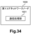
4.4.第1コアネットワークノードの構成例
4.5.処理の流れ
4.6.変形例
5.第3の実施形態
5.1.システムの構成例
5.2.HNB−GWの構成例
5.3.SGSNの構成例
5.4.処理の流れ
5.5.変形例
6.第4の実施形態
6.1.システムの構成例
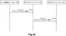
6.2.ホーム基地局ゲートウェイの構成例
6.3.第1コアネットワークノードの構成例
6.4.処理の流れ
7.第5の実施形態
7.1.システムの構成例
7.2.C−RANの構成例
7.3.MMEの構成例
7.4.処理の流れ
7.5.変形例
8.他の実施形態The description will be made in the following order.
1.
<<1.関連技術>>
図1〜図8を参照して、本発明の実施形態に関連する技術として、固定ブロードバンドアクセスネットワークの制御、ホームアクセスネットワークにおけるハンドオーバの手続き、デュアルコネクティビティのSeNBの変更の手続き、及びCSG(Closed Subscriber Group)に関する手続きを説明する。<< 1. Related technology >>
Referring to FIG. 1 to FIG. 8, as technologies related to the embodiment of the present invention, fixed broadband access network control, handover procedure in home access network, dual connectivity SeNB change procedure, and CSG (Closed Subscriber) Group).
(1)固定ブロードバンドアクセスネットワークの制御
3GPP(Third Generation Partnership Project)システムの構成要素を固定ブロードバンドアクセスネットワークが接続している場合に、3GPPシステムのPCRF(Policy and Charging Rules Function)は、P−GW(Packet data network Gateway)から受け取った基地局のローカルIPアドレス(即ち、IPsecトンネルのouter IPアドレス)及びUDPポート番号を、PCRF内のQoS(Quality of Service)情報とともに固定ブロードバンドアクセスネットワークへ送信する。(1) Control of fixed broadband access network When fixed broadband access network is connected to the components of 3GPP (Third Generation Partnership Project) system, PCRF (Policy and Charging Rules Function) of 3GPP system is P-GW ( The local IP address of the base station (ie, the outer IP address of the IPsec tunnel) and the UDP port number received from the packet data network gateway) are transmitted to the fixed broadband access network together with QoS (Quality of Service) information in the PCRF.
固定ブロードバンドアクセスネットワークは、上記QoS情報をDSCP(Differentiated Service Code Point)に変換し、PCRFから受信した上記ローカルIPアドレスと上記UDPポート番号に対応付けられる回線への適用を行い、3GPPシステムの利用者用の帯域の制御を行う。 The fixed broadband access network converts the QoS information into DSCP (Differentiated Service Code Point), applies it to the line associated with the local IP address and the UDP port number received from the PCRF, and uses the 3GPP system user. Control the bandwidth for use.
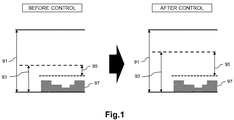
−帯域制御の例
図1〜図3は、帯域制御の例を説明するための説明図である。図1〜図3を参照すると、帯域制御前と帯域制御後の帯域91、帯域93、帯域95及び帯域97が示されている。帯域91は、3GPPシステムの利用者が使用している基地局を収容している回線の全帯域である。帯域93は、3GPPシステムの利用者が使用している基地局のために確保している帯域である。帯域95は、3GPPシステムの利用者を新たに受け入れ可能な帯域である。帯域97は、実際に使用されている帯域である。例えば、図1に示されるように、帯域93(3GPPシステムの利用者が使用している基地局のために確保している帯域)の上限値が調整され得る。例えば、図2に示されるように、3GPPシステムの利用者が増えた回線では、帯域95(3GPPシステムの利用者を新たに受け入れ可能な帯域)が減らされ得る。例えば、図3に示されるように、3GPPシステムの利用者が減った回線では、帯域95(3GPPシステムの利用者を新たに受け入れ可能な帯域)が増やされ得る。このような帯域制御の手法が、3GPP TS23.139 V12.2.0に示されている。Example of Band Control FIGS. 1 to 3 are explanatory diagrams for explaining an example of band control. 1 to 3 show a
なお、基地局は、帯域93(3GPPシステムの利用者が使用している基地局のために確保している帯域)の上限値、及び/又は、帯域95(3GPPシステムの利用者を新たに受け入れ可能な帯域)に基づいて、3GPPシステムの利用者の通信品質の維持/向上のみではなく、アドミッションコントロール(Admission Control)も行う。当該アドミッションコントロールは、ハンドオーバされるUE(User Equipment)の無線アクセスベアラ(Radio Access Bearer:RAB)の受け入れ可否を決めることを含む。これにより、基地局ごとのRABの収容数が適正化され得る。 In addition, the base station newly accepts the upper limit value of the band 93 (band reserved for the base station used by the user of the 3GPP system) and / or the band 95 (user of the 3GPP system). In addition to maintaining / improving communication quality of users of the 3GPP system, admission control is also performed based on the available bandwidth. The admission control includes determining whether or not to accept a radio access bearer (RAB) of a user equipment (UE) to be handed over. Thereby, the accommodation number of RAB for every base station can be optimized.
−処理の流れ(第1の例)
図4は、固定ブロードバンドアクセスネットワークのための手続きの第1の例を説明するためのシーケンス図である。図4は、通信方式としてWCDMA(Wideband Code-Division Multiple Access)(登録商標)が使用されるケースの例であり、3GPP TS23.139 V12.2.0のFigure 9.3.4−1である。-Flow of processing (first example)
FIG. 4 is a sequence diagram for explaining a first example of a procedure for a fixed broadband access network. FIG. 4 is an example of a case where WCDMA (Wideband Code-Division Multiple Access) (registered trademark) is used as a communication method, and is FIG. 9.3.4-1 of 3GPP TS23.139 V12.2.0. .
ステップ1で、ターゲットHNBは、ターゲットHNBローカルIPアドレス及びUDPポート番号をターゲットSGSN(Serving GPRS(General Packet Radio Service) Support Node)へ送信する。
In
ステップ2aで、ターゲットSGSNは、ターゲットHNBローカルIPアドレス及びUDPポート番号をS−GW(Serving Gateway)へ送信し、ステップ2bで、S−GWは、ターゲットHNBローカルIPアドレス及びUDPポート番号をP−GWへ送信する。
In
ステップ3で、P−GWは、ターゲットHNBローカルIPアドレス及びUDPポート番号をPCRFへ送信する。
In
ステップ4で、PCRFは、ターゲットHNBローカルIPアドレス及びUDPポート番号を固定ブロードバンドアクセスネットワークへ送信する。
In
なお、図4におけるステップ2aは、以下のような処理がステップ1で実行されることを契機として実行される。
−Inter SGSN Routing Area Update and Combined Inter SGSN RA / LA Update using S4
−Routing Area Update Procedure using S4
−Serving RNS Relocation Procedure, Combined Hard Handover and SRNS Relocation Procedure, and Combined Cell / URA Update and SRNS Relocation Procedure Using S4
−Enhanced Serving RNS Relocation Procedure using S4
−UE Initiated Service Request Procedure Using S4
−Iu mode to A/Gb mode Intra SGSN Change using S4
−A/Gb mode to Iu mode Intra-SGSN Change using S4
−Iu mode to A/Gb mode Inter-SGSN Change using S4
−A/Gb mode to Iu mode Inter-SGSN Change using S4Note that
−Inter SGSN Routing Area Update and Combined Inter SGSN RA / LA Update using S4
−Routing Area Update Procedure using S4
−Serving RNS Relocation Procedure, Combined Hard Handover and SRNS Relocation Procedure, and Combined Cell / URA Update and SRNS Relocation Procedure Using S4
−Enhanced Serving RNS Relocation Procedure using S4
−UE Initiated Service Request Procedure Using S4
−Iu mode to A / Gb mode Intra SGSN Change using S4
−A / Gb mode to Iu mode Intra-SGSN Change using S4
−Iu mode to A / Gb mode Inter-SGSN Change using S4
−A / Gb mode to Iu mode Inter-SGSN Change using S4
−処理の流れ(第1の例)
図5は、固定ブロードバンドアクセスネットワークのための手続きの別の例を説明するためのシーケンス図である。図5は、通信方式としてLTE(Long Term Evolution)が使用されるケースの例であり、3GPP TS23.139 V12.2.0のFigure 9.1.5である。-Flow of processing (first example)
FIG. 5 is a sequence diagram for explaining another example of the procedure for the fixed broadband access network. FIG. 5 is an example of a case where LTE (Long Term Evolution) is used as a communication method, which is FIG. 9.1.5 of 3GPP TS23.139 V12.2.0.
ステップ2で、ターゲットHeNBは、ターゲットHeNBローカルIPアドレス及びUDPポート番号をMMEへ送信する。
In
ステップ3で、MMEは、ターゲットHeNBローカルIPアドレス及びUDPポート番号をS−GWへ送信し、S−GWは、ターゲットHeNBローカルIPアドレス及びUDPポート番号をP−GWへ送信する。
In
ステップ4で、P−GWは、ターゲットHeNBローカルIPアドレス及びUDPポート番号をPCRFへ送信する。
In
ステップ5で、PCRFは、ターゲットHeNBローカルIPアドレス及びUDPポート番号を固定ブロードバンドアクセスネットワークへ送信する。
In
なお、図5におけるステップ2は、以下のような処理がステップ1で実行されることを契機として実行される。
−UE initiated Service Request
−X2-based handover without Serving GW relocation
−X2-based handover with Serving GW relocation
−S1-based handover
−inter-RAT Handover from UTRAN Iu Mode to E-UTRAN
−inter-RAT handover from GERAN A/Gb Mode to E-UTRANNote that
−UE initiated Service Request
−X2-based handover without Serving GW relocation
−X2-based handover with Serving GW relocation
−S1-based handover
−inter-RAT Handover from UTRAN Iu Mode to E-UTRAN
−inter-RAT handover from GERAN A / Gb Mode to E-UTRAN
(2)ホームアクセスネットワークにおけるハンドオーバの手続き
−第1の例
図6は、ホームアクセスネットワークにおけるハンドオーバ手続きの第1の例を説明するための説明図である。図6は、3GPP TS25.467 V12.3.0のFigure 5.7.2.1−1である。この例では、ソースHNBからターゲットHNBへのUEのハンドオーバが行われる。ソースHNBとターゲットHNBとの間には、Iurhというインターフェースがあり、ソースHNB及びターゲットHNBは、HNB−GW(Home Node B Gateway)を介さずに、直接的にメッセージを交換する。(2) Handover Procedure in Home Access Network—First Example FIG. 6 is an explanatory diagram for explaining a first example of a handover procedure in the home access network. FIG. 6 is FIG. 5.7.2.1-1 of 3GPP TS25.467 V12.3.0. In this example, the UE is handed over from the source HNB to the target HNB. There is an interface called Iurh between the source HNB and the target HNB, and the source HNB and the target HNB exchange messages directly without going through an HNB-GW (Home Node B Gateway).
図6に示される手続きにおいて、ステップ8a/8b(RABを解放する必要が生じた場合にのみ実行されるステップ)を除き、HNBからCN(Core Network)へ送信されるメッセージは存在しない。そのため、図6の例では、ターゲットHeNBローカルIPアドレス及びUDPポート番号は、SGSN、S−GW及びP−GWを通じてPCRFに送信されない。その結果、固定ブロードバンドアクセスネットワークの制御(例えば、帯域制御)がPCRFを通じて行われず、3GPPシステムの利用者の通信品質の維持/向上、及び/又は、基地局毎のRABの収容数の適正化が、不可能になり得る。 In the procedure shown in FIG. 6, there is no message transmitted from the HNB to the CN (Core Network) except for steps 8a / 8b (steps executed only when the RAB needs to be released). Therefore, in the example of FIG. 6, the target HeNB local IP address and the UDP port number are not transmitted to the PCRF through the SGSN, S-GW, and P-GW. As a result, control of the fixed broadband access network (for example, bandwidth control) is not performed through the PCRF, and maintenance / improvement of communication quality of users of the 3GPP system and / or optimization of the number of RABs accommodated for each base station is achieved. Can be impossible.
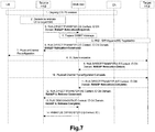
−第2の例
図7は、ホームアクセスネットワークにおけるハンドオーバ手続きの第2の例を説明するための説明図である。図7は、3GPP TS25.467 V12.3.0のFigure A.3−1である。この例では、ソースHNBからターゲットHNBへのUEのハンドオーバが行われる。ソースHNBとターゲットHNBとの間には、Iurhというインターフェースが存在せず、IuhインターフェースでソースHNB及びターゲットHNBと通信するHNB−GWが、ハンドオーバ処理を司る。Second Example FIG. 7 is an explanatory diagram for explaining a second example of the handover procedure in the home access network. FIG. 7 shows the figure A.3 of 3GPP TS25.467 V12.3.0. 3-1. In this example, the UE is handed over from the source HNB to the target HNB. There is no Iurh interface between the source HNB and the target HNB, and the HNB-GW that communicates with the source HNB and the target HNB via the Iuh interface manages the handover process.
図7に示される手続きにおいて、HNB−GWからCNへ送信されるメッセージは存在しない。そのため、図7の例でも、ターゲットHeNBローカルIPアドレス及びUDPポート番号は、SGSN、S−GW及びP−GWを通じてPCRFに送信されない。その結果、固定ブロードバンドアクセスネットワークの制御(例えば、帯域制御)がPCRFを通じて行われず、3GPPシステムの利用者の通信品質の維持/向上、及び/又は、基地局毎のRABの収容数の適正化が、不可能になり得る。 In the procedure shown in FIG. 7, there is no message transmitted from the HNB-GW to the CN. Therefore, also in the example of FIG. 7, the target HeNB local IP address and UDP port number are not transmitted to the PCRF through the SGSN, S-GW, and P-GW. As a result, control of the fixed broadband access network (for example, bandwidth control) is not performed through the PCRF, and maintenance / improvement of communication quality of users of the 3GPP system and / or optimization of the number of RABs accommodated for each base station is achieved. Can be impossible.
(3)デュアルコネクティビティのSeNBの変更の手続き
図8は、SeNBの変更の手続きの例を説明するための説明図である。図8は、3GPP TS36.300 V13.0.0のFigure 10.1.2.8.4−1である。この例では、デュアルコネクティビティのケイパビリティを有するUEが、MeNB及びSeNBに接続されている場合に、当該SeNBが、S−SeNB(Source Secondary eNB)からT−SeNB(Target Secondary eNB)に変更される。(3) Dual Connectivity SeNB Change Procedure FIG. 8 is an explanatory diagram for explaining an example of a SeNB change procedure. FIG. 8 is FIG. 10.1.2.8.4-1 of 3GPP TS36.300 V13.0.0. In this example, when a UE having the dual connectivity capability is connected to the MeNB and SeNB, the SeNB is changed from S-SeNB (Source Secondary eNB) to T-SeNB (Target Secondary eNB).
例えば、S−SeNBにおいてベアラコンテキスト(bearer context)の1つにSCG(Secondary Cell Group)ベアラオプションが設定されている場合には、ステップ10で、MeNBは、S1AP:E−RAB MODIFICATION INDICATIONメッセージをMMEへ送信する。そして、MMEは、このメッセージの受信に応じて、S−GWにBearer Modificationを要求する。しかし、S1AP:E−RAB MODIFICATION INDICATIONメッセージには、T−SeNBのローカルIPアドレス及びUDPポート番号が含まれないので、MMEは、SCGベアラがS−SeNBからT−SeNBに移ったことをS−GWに通知できない。そのため、PCRFは、T−SeNBのローカルIPアドレス及びUDPポート番号を通知されないので、固定ブロードバンドアクセスネットワークの制御(例えば、帯域制御)が行われない。その結果、3GPPシステムの利用者の通信品質の維持/向上、及び/又は、基地局毎のRABの収容数の適正化が、不可能になり得る。
For example, when the SCG (Secondary Cell Group) bearer option is set in one of the bearer contexts in the S-SeNB, the MeNB sends an S1AP: E-RAB MODIFICATION INDICATION message to the MME in
例えば、S−SeNBにおいていずれのベアラコンテキストにもSCGベアラオプションが設定されていない場合には(即ち、スプリットベアラしか存在しない場合には)、ステップ10が実行されない。そのため、同様に、3GPPシステムの利用者の通信品質の維持/向上、及び/又は、基地局毎のRABの収容数の適正化が、不可能になり得る。
For example, when the SCG bearer option is not set in any bearer context in the S-SeNB (that is, when only the split bearer exists),
(4)CSGに関する手続き
3GPP TS36.300 V13.0.0には、ハイブリッドセルをeNBが構成できると定められている。ハイブリッドセルでは、CSG IDという識別子で識別されるCSGに属する利用者は、ハイブリッドセルをCSGセルとして使用し、CSGに属さない利用者は、ハイブリッドセルを通常のセルとして使用する。(4) Procedure for CSG 3GPP TS36.300 V13.0.0 stipulates that an eNB can configure a hybrid cell. In a hybrid cell, a user belonging to a CSG identified by an identifier called CSG ID uses the hybrid cell as a CSG cell, and a user who does not belong to the CSG uses the hybrid cell as a normal cell.
ハイブリッドセルを構成するeNBは、ハンドオーバされるUEを受け入れるか否かを決定する際に、及び、ハンドオーバされるUEを受け入れる場合にどのベアラを受け入れ、どのベアラを拒否するかを決定する際に、ハイブリッドセルをCSGセルとして使用する利用者を、ハイブリッドセルを通常のセルとして使用する利用者よりも優遇してもよい。 When the eNB that constitutes the hybrid cell decides whether to accept the UE to be handed over, and when to decide which bearer to accept and reject which bearer when accepting the UE to be handed over A user who uses a hybrid cell as a CSG cell may be favored over a user who uses a hybrid cell as a normal cell.
例えば、SeNBが、ハイブリッドセルを構成する。この場合に、MeNBは、SeNBのハイブリッドセルで報知されているCSG IDをUEから受信し、当該CSG IDをMMEに報告する。そして、MMEは、UEがSeNBのハイブリッドセルをCSGセルとして使用するか又は通常のセルとして使用するかを決定する。例えば、3GPP R3−151949及び3GPP R3−151995には、この決定の手順の候補が開示されている。 For example, the SeNB configures a hybrid cell. In this case, MeNB receives CSG ID currently alert | reported by the hybrid cell of SeNB from UE, and reports the said CSG ID to MME. And MME determines whether UE uses the hybrid cell of SeNB as a CSG cell or a normal cell. For example, 3GPP R3-1151949 and 3GPP R3-151995 disclose candidate determination procedures.
3GPP R3−151949では、SeNBにおいてベアラコンテキストの1つにSCGベアラオプションが設定されている場合には、MeNBは、上記CSG ID(SeNBのハイブリッドセルで報知されているCSG ID)を含むS1AP:E−RAB MODIFICATION INDICATIONメッセージをMMEへ送信する。一方、SeNBにおいていずれのベアラコンテキストにもSCGベアラオプションが設定されていない場合には(即ち、スプリットベアラしか存在しない場合には)、MeNBは、上記CSG IDを含むS1AP:UE CONTEXT MODIFICATION INDICATIONメッセージ(新たなメッセージ)をMMEへ送信する。 In 3GPP R3-1151949, when the SCG bearer option is set in one of the bearer contexts in the SeNB, the MeNB includes the CSG ID (CSG ID broadcasted in the SeNB hybrid cell) S1AP: E -Send a RAB MODIFICATION INDICATION message to the MME. On the other hand, when the SCG bearer option is not set in any bearer context in the SeNB (that is, when only the split bearer exists), the MeNB sends an S1AP: UE CONTEXT MODIFICATION INDICATION message (including the CSG ID) ( A new message) is sent to the MME.
3GPP R3−151995では、SCGベアラオプションの設定の有無にかかわらず、MeNBは、上記CSG ID(SeNBのハイブリッドセルで報知されているCSG ID)を含むS1AP:E−RAB MODIFICATION INDICATIONメッセージをMMEへ送信する。 In 3GPP R3-151995, the MeNB transmits an S1AP: E-RAB MODIFICATION INDICATION message including the CSG ID (CSG ID broadcasted in the SeNB hybrid cell) to the MME regardless of whether the SCG bearer option is set or not. To do.
上述したいずれの場合にも、MeNBがMMEへ送信するメッセージには、SeNBのローカルIPアドレス及びUDPポート番号は含まれていない。そのため、例えば、固定ブロードバンドアクセスネットワークの帯域制御が行われない。その結果、3GPPシステムの利用者の通信品質の維持/向上、及び/又は、基地局毎のRABの収容数の適正化が、不可能になり得る。 In any case described above, the message transmitted from the MeNB to the MME does not include the local IP address and UDP port number of the SeNB. Therefore, for example, bandwidth control of a fixed broadband access network is not performed. As a result, it may be impossible to maintain / improve communication quality of users of the 3GPP system and / or optimize the number of RABs accommodated for each base station.
<<2.本発明の実施形態の概要>>
続いて、本発明の実施形態の概要を説明する。<< 2. Outline of Embodiment of the Present Invention >>
Subsequently, an outline of an embodiment of the present invention will be described.
(1)技術的課題
3GPPシステムの構成要素を固定ブロードバンドアクセスネットワークが接続している場合に、3GPPシステムのPCRFは、P−GWから受け取った基地局のローカルIPアドレス(即ち、IPsecトンネルのouter IPアドレス、パブリックIPアドレス、又はグローバルIPアドレス)及びUDPポート番号を、PCRF内のQoS情報とともに固定ブロードバンドアクセスネットワークへ送信する。(1) Technical issues When a fixed broadband access network connects the components of the 3GPP system, the PCRF of the 3GPP system receives the local IP address of the base station received from the P-GW (ie, the outer IP of the IPsec tunnel). Address, public IP address, or global IP address) and UDP port number are sent to the fixed broadband access network along with the QoS information in the PCRF.
固定ブロードバンドアクセスネットワークは、上記QoS情報をDSCPに変換し、PCRFから受信した上記ローカルIPアドレスと上記UDPポート番号に対応付けられる回線への適用を行い、3GPPシステムの利用者用の帯域の制御を行う。 The fixed broadband access network converts the QoS information into DSCP, applies it to the line associated with the local IP address received from the PCRF and the UDP port number, and controls the bandwidth for the user of the 3GPP system. Do.
しかし、3GPPの仕様(specification)によれば、ローカルIPアドレス及びUDPポート番号が、コアネットワークノードへ送信されないケースがある。一例として、デュアルコネクティビティのSeNBの変更の際には、変更後のSeNBのローカルIPアドレス及びUDPポート番号は、コアネットワークへ送信されていない。別の例として、同一のHNB−GWにサービスを提供されるHNB間のハンドオーバの際には、ターゲットHNBのローカルIPアドレス及びUDPポート番号は、コアネットワークへ送信されていない。その結果、固定ブロードバンドアクセスネットワークの制御(例えば、帯域制御)がPCRFを通じて行われず、3GPPシステムの利用者の通信品質の維持/向上、及び/又は、基地局毎のRABの収容数の適正化が、不可能になり得る。 However, according to the 3GPP specification (specification), the local IP address and the UDP port number may not be transmitted to the core network node. As an example, when changing the dual connectivity SeNB, the local IP address and UDP port number of the SeNB after the change are not transmitted to the core network. As another example, during handover between HNBs served by the same HNB-GW, the local IP address and UDP port number of the target HNB are not transmitted to the core network. As a result, control of the fixed broadband access network (for example, bandwidth control) is not performed through the PCRF, and maintenance / improvement of communication quality of users of the 3GPP system and / or optimization of the number of RABs accommodated for each base station is achieved. Can be impossible.
本発明の実施形態の目的は、より多くのケースにおいて、例えば固定ブロードバンドアクセスネットワークの制御に必要な情報をコアネットワークノードが取得することを可能にすることにある。 An object of embodiments of the present invention is to allow the core network node to obtain information necessary for controlling, for example, a fixed broadband access network in more cases.
(2)技術的特徴
(a)第1の実施形態及び第2の実施形態
本発明の第1の実施形態及び第2の実施形態では、例えば、SeNBが、ソースSeNBからターゲットSeNBに変更される。この場合に、例えば、MeNBは、上記ターゲットSeNBのアドレス情報(例えば、IPアドレス)及びトランスポート識別情報(例えば、UDPポート番号)を含むメッセージを、MMEへ送信する。そして、例えば、当該MMEは、当該メッセージを受信する。(2) Technical features (a) First embodiment and second embodiment In the first embodiment and the second embodiment of the present invention, for example, the SeNB is changed from the source SeNB to the target SeNB. . In this case, for example, the MeNB transmits a message including address information (for example, an IP address) and transport identification information (for example, a UDP port number) of the target SeNB to the MME. For example, the MME receives the message.
これにより、例えば、デュアルコネクティビティのケース(具体的には、SeNBの変更のケース)においても固定ブロードバンドアクセスネットワークの制御に必要な情報をコアネットワークノードが取得することが可能になる。その結果、3GPPシステムの利用者の通信品質が維持/向上され、基地局毎のRABの収容数が適正化され得る。 Thereby, for example, even in the case of dual connectivity (specifically, the case of SeNB change), the core network node can acquire information necessary for controlling the fixed broadband access network. As a result, communication quality of users of the 3GPP system can be maintained / improved, and the number of RABs accommodated for each base station can be optimized.
(b)第3の実施形態及び第4の実施形態
本発明の第3の実施形態及び第4の実施形態では、例えば、UEと通信するHNBが、ソースHNBからターゲットHNBに変更される。この場合に、例えば、HNB−GWは、上記ターゲットHNBのアドレス情報(例えば、IPアドレス)及びトランスポート識別情報(例えば、UDPポート番号)を含むメッセージを、SGSNコアネットワークノードへ送信する。そして、例えば、当該SGSNは、当該メッセージを受信する。(B) Third Embodiment and Fourth Embodiment In the third embodiment and the fourth embodiment of the present invention, for example, the HNB communicating with the UE is changed from the source HNB to the target HNB. In this case, for example, the HNB-GW transmits a message including address information (for example, IP address) and transport identification information (for example, UDP port number) of the target HNB to the SGSN core network node. Then, for example, the SGSN receives the message.
これにより、例えば、ホームアクセスネットワークのケース(具体的には、同じHNB−GWにサービスを提供されるHNB間でのハンドオーバのケース)においても固定ブロードバンドアクセスネットワークの制御に必要な情報をコアネットワークノードが取得することが可能になる。その結果、3GPPシステムの利用者の通信品質が維持/向上され、基地局毎のRABの収容数が適正化され得る。 Thus, for example, even in the case of a home access network (specifically, a case of handover between HNBs that provide services to the same HNB-GW), information necessary for controlling the fixed broadband access network is stored in the core network node. Will be able to get. As a result, communication quality of users of the 3GPP system can be maintained / improved, and the number of RABs accommodated for each base station can be optimized.
なお、上述した技術的特徴は本発明の実施形態の具体的な一例であり、当然ながら、本発明の実施形態は上述した技術的特徴に限定されない。 The technical features described above are specific examples of the embodiments of the present invention, and the embodiments of the present invention are naturally not limited to the technical features described above.
<<3.第1の実施形態>>
続いて、図9〜図20を参照して、本発明の第1の実施形態を説明する。<< 3. First Embodiment >>
Subsequently, a first embodiment of the present invention will be described with reference to FIGS.
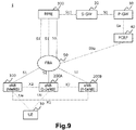
<3.1.システムの構成例>
図9を参照して、第1の実施形態に係るシステム1の構成の例を説明する。図9は、第1の実施形態に係るシステム1の概略的な構成の一例を示す説明図である。図9を参照すると、システム1は、UE10、eNB100、eNB200A、eNB200B、MME300、S−GW20、P−GW30、PCRF40及びFBA(Fixed Broadband Access)50を含む。なお、eNB200A及びeNB200Bの区別が必要ない場合には、eNB200A及びeNB200Bの各々は、単にeNB200と呼ばれ得る。<3.1. System configuration example>
An example of the configuration of the
UE10は、デュアルコネクティビティをサポートし、MeNB及びSeNBと通信可能である。また、eNB100は、MeNBとして動作可能なeNBであり、eNB200は、SeNBとして動作可能なeNBである。一例として、eNB100は、マクロセルのeNB(マクロeNB)であり、eNB200は、スモールセル(例えば、マイクロセル、ピコセル又はフェムトセル等)のeNB(スモールeNB)である。一例として、eNB200は、ホームeNBである。なお、eNB100及びeNB200はこの例に限定されない。
UE10 supports dual connectivity and can communicate with MeNB and SeNB. Moreover, eNB100 is eNB which can operate | move as MeNB, and eNB200 is eNB which can operate | move as SeNB. As an example, the
とりわけこの例では、まず、eNB100が、UE10のためのMeNBとして動作し、eNB200Aが、UE10のためのSeNBとして動作しており、UE10は、eNB100(MeNB)及びeNB200A(SeNB)と通信している。その後、例えば、UE10の移動に伴い、SeNBが、eNB200A(S−SeNB)からeNB200B(T−SeNB)に変更される。その結果、UE10は、eNB100(MeNB)及びeNB200B(SeNB)と通信するようになる。
In particular, in this example, first, the
eNB100は、eNB200A及びeNB200Bの各々とX2インターフェースを介して接続されている。eNB100とeNB200との間には、X2ゲートウェイ(X2GW)が存在してもよい。さらに、eNB100、eNB200A及びeNB200Bの各々は、S1インターフェースを介してMMEと接続されている。MME300は、S11インターフェースを介してS−GW20と接続されている。S−GW20は、S5インターフェースを介してP−GW30と接続されている。
The
PCRFは、ネットワークにポリシーを設定するノードであり、Gxインターフェースを介してP−GW30と接続され、S9aインターフェースを介してFBA50と接続されている。
The PCRF is a node that sets a policy in the network, and is connected to the P-
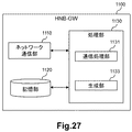
<3.2.eNB(MeNB)の構成例>
次に、図10及び図11を参照して、第1の実施形態に係るeNB100の構成の例を説明する。図10は、第1の実施形態に係るeNB100の概略的な構成の例を示すブロック図である。図10を参照すると、eNB100は、無線通信部110、ネットワーク通信部120、記憶部130及び処理部140を備える。<3.2. Configuration example of eNB (MeNB)>
Next, an example of the configuration of the
(1)無線通信部110
無線通信部110は、信号を無線で送受信する。例えば、無線通信部110は、UEからの信号を受信し、UEへの信号を送信する。(1)
The
(2)ネットワーク通信部120
ネットワーク通信部120は、ネットワーク(例えば、バックホール)から信号を受信し、当該ネットワークへ信号を送信する。(2)
The
(3)記憶部130
記憶部130は、eNB100の動作のためのプログラム及びパラメータ、並びに様々なデータを、一時的に又は恒久的に記憶する。(3)
The
(4)処理部140
処理部140は、eNB100の様々な機能を提供する。処理部140は、第1通信処理部141、第2通信処理部143及び生成部145を含む。なお、処理部140は、これらの構成要素以外の他の構成要素をさらに含み得る。即ち、処理部140は、これらの構成要素の動作以外の動作も行い得る。(4)
The
例えば、処理部140(第1通信処理部141)は、無線通信部110を介してUEと通信する。例えば、処理部140(第2通信処理部143)は、ネットワーク通信部120を介して他のネットワークノード(例えば、eNB200又はMME300等)と通信する。
For example, the processing unit 140 (first communication processing unit 141) communicates with the UE via the
(5)実装
無線通信部110は、アンテナ及び高周波(Radio Frequency:RF)回路などを含んでもよい。ネットワーク通信部120は、ネットワークアダプタ又はネットワークインタフェースカードなどを含んでもよい。記憶部130は、メモリ(例えば、不揮発性メモリ及び/若しくは揮発性メモリ)並びに/又はハードディスクなどを含んでもよい。処理部140は、ベースバンド(Baseband:BB)プロセッサ及び/又は他のプロセッサなどを含んでもよい。(5) Mounting The
(6)技術的特徴
例えば、eNB100がUE10のためのMeNBとして動作している場合に、UE10のためのSeNB(即ち、デュアルコネクティビティにおいて追加の無線リソースをUE10に提供するSeNB)が、eNB200A(ソースSeNB)からeNB200B(ターゲットSeNB)に変更される。この場合に、eNB100(第2通信処理部143)は、eNB200B(即ち、ターゲットSeNB)のアドレス情報及びトランスポート識別情報を含む第1のメッセージを、コアネットワークノードへ送信する。例えば、eNB100(生成部145)は、上記第1のメッセージを生成する。(6) Technical features For example, when the
これにより、例えば、デュアルコネクティビティのケース(具体的には、SeNBの変更のケース)においても固定ブロードバンドアクセスネットワークの制御に必要な情報をコアネットワークノードが取得することが可能になる。その結果、3GPPシステムの利用者の通信品質が維持/向上され、基地局毎のRABの収容数が適正化され得る。 Thereby, for example, even in the case of dual connectivity (specifically, the case of SeNB change), the core network node can acquire information necessary for controlling the fixed broadband access network. As a result, communication quality of users of the 3GPP system can be maintained / improved, and the number of RABs accommodated for each base station can be optimized.
(a)コアネットワークノード
例えば、上記コアネットワークノードは、MME300である。(A) Core network node For example, the core network node is the
(b)トンネル情報
例えば、上記第1のメッセージは、上記アドレス情報及び上記トランスポート識別情報を含むトンネル情報を含む。より具体的には、例えば、当該トンネル情報は、Tunnel Information for BBF IEである。Tunnel Information for BBF IEは、IPアドレス(アドレス情報)及びUDPポート番号(トランスポート識別情報)を含む。(B) Tunnel information For example, the first message includes tunnel information including the address information and the transport identification information. More specifically, for example, the tunnel information is Tunnel Information for BBF IE. The Tunnel Information for BBF IE includes an IP address (address information) and a UDP port number (transport identification information).
(c)第1のメッセージ
例えば、上記第1のメッセージは、S1AP:E−RAB MODIFICATION INDICATIONメッセージである。(C) First message For example, the first message is an S1AP: E-RAB MODIFICATION INDICATION message.
例えば、UE10及びeNB200A(S−SeNB)についてのSCGベアラがある場合に、eNB100(第2通信処理部143)は、S1AP:E−RAB MODIFICATION INDICATIONメッセージを上記コアネットワークノードへ送信する。
For example, when there is an SCG bearer for the
さらに、例えば、UE10及びeNB200A(S−SeNB)についてのSCGベアラがない場合であっても(即ち、スプリットベアラしかない場合であっても)、eNB100(第2通信処理部143)は、S1AP:E−RAB MODIFICATION INDICATIONメッセージを上記コアネットワークノードへ送信する。これにより、SCGベアラの有無にかかわらず、同じメッセージを使用してアドレス情報及びトランスポート識別情報を伝えることが可能になる。
Furthermore, for example, even when there is no SCG bearer for the
図11は、第1の実施形態に係るS1AP:E−RAB MODIFICATION INDICATIONメッセージの例を説明するための説明図である。図11を参照すると、S1AP:E−RAB MODIFICATION INDICATIONメッセージに含まれる情報要素(Information Element:IE)が示されている。とりわけ、S1AP:E−RAB MODIFICATION INDICATIONメッセージは、IPアドレス(アドレス情報)及びUDPポート番号(トランスポート識別情報)を含むTunnel Information for BBF IEを含む。 FIG. 11 is an explanatory diagram for explaining an example of the S1AP: E-RAB MODIFICATION INDICATION message according to the first embodiment. Referring to FIG. 11, an information element (IE) included in the S1AP: E-RAB MODIFICATION INDICATION message is shown. In particular, the S1AP: E-RAB MODIFICATION INDICATION message includes a Tunnel Information for BBF IE including an IP address (address information) and a UDP port number (transport identification information).
なお、UE10及びeNB200A(S−SeNB)についてのSCGベアラがない場合には(即ち、スプリットベアラしかない場合には)、eNB100(第2通信処理部143)は、他の種類のメッセージを上記コアネットワークノードへ送信してもよい。 In addition, when there is no SCG bearer about UE10 and eNB200A (S-SeNB) (namely, when there is only a split bearer), eNB100 (2nd communication process part 143) sends other types of messages to said core You may transmit to a network node.
以上、eNB100により送信される上記第1のメッセージの例を説明したが、当然ながら、eNB100により送信される上記第1のメッセージはこの例に限定されない。eNB100により送信される上記第1のメッセージは他の種類のメッセージであってもよい。
As mentioned above, although the example of the said 1st message transmitted by eNB100 was demonstrated, naturally the said 1st message transmitted by eNB100 is not limited to this example. The first message transmitted by the
また、eNB100(生成部145)は、上記第1のメッセージを自ら生成する代わりに、上記第1のメッセージを他のノードから取得してもよい。 Also, the eNB 100 (generating unit 145) may acquire the first message from another node instead of generating the first message by itself.
(d)アドレス情報及びトランスポート識別情報
−受信
例えば、eNB100(第2通信処理部143)は、上記アドレス情報及び上記トランスポート識別情報を含む第2のメッセージを受信する。当該第2のメッセージは、eNB200により送信されるメッセージである。この点については、eNB200に関連して後述する。これにより、例えば、eNB100は、eNB200のアドレス情報及びトランスポート識別情報を知ることが可能になる。(D) Address information and transport identification information-reception For example, the eNB 100 (second communication processing unit 143) receives the second message including the address information and the transport identification information. The second message is a message transmitted by the
−アドレス情報
例えば、上記アドレス情報は、(OSI(Open System Interconnection)参照モデルの)ネットワークレイヤ又は(TCP/IP(Transmission Control Protocol/Internet Protocol)の)インターネットレイヤの識別情報(アドレス)である。具体的には、例えば、上記アドレス情報は、IPアドレスである。さらに、例えば、当該IPアドレスは、パブリックIPアドレス(又はグローバルIPアドレス)である。例えば、上記IPアドレスは、no−NAT(Network Address Translation)ケースでBBFドメインによりeNB200B(即ち、ターゲットSeNB)にアサインされたパブリックIPアドレス、又は、NATを行う RG(Residential Gateway)(即ち、NATed RG)にBBFドメインによりアサインされたパブリックIPアドレスであって、eNB200Bのために使用される当該パブリックIPアドレスである。なお、上記IPアドレスは、3GPPの仕様においては「ローカルIPアドレス」と呼ばれ得る。-Address information For example, the address information is identification information (address) of the network layer (of the OSI (Open System Interconnection) reference model) or the Internet layer (of TCP / IP (Transmission Control Protocol / Internet Protocol)). Specifically, for example, the address information is an IP address. Further, for example, the IP address is a public IP address (or a global IP address). For example, the IP address is a public IP address assigned to the eNB 200B (ie, the target SeNB) by the BBF domain in a no-NAT (Network Address Translation) case, or an RG (Residential Gateway) (ie, NATed RG) that performs NAT. The public IP address assigned by the BBF domain to the eNB 200B. The IP address can be referred to as a “local IP address” in the 3GPP specifications.
−トランスポート識別情報
例えば、上記トランスポート識別情報は、(OSI参照モデル又はTCP/IPの)トランスポートレイヤの識別情報である。具体的には、例えば、上記トランスポート識別情報は、UDPポート番号である。-Transport identification information For example, the transport identification information is identification information of a transport layer (OSI reference model or TCP / IP). Specifically, for example, the transport identification information is a UDP port number.
−提供先
例えば、上記アドレス情報及び上記トランスポート識別情報は、FBA50に提供される情報である。より具体的には、例えば、上記アドレス情報及び上記トランスポート識別情報は、PCRF40からFBA50に提供される情報である。これにより、例えば、帯域制御が行われ得る。-Destination For example, the address information and the transport identification information are information provided to the
<3.3.eNB(SeNB)の構成例>
次に、図12〜図17を参照して、第1の実施形態に係るeNB200の構成の例を説明する。図12は、第1の実施形態に係るeNB200の概略的な構成の例を示すブロック図である。図12を参照すると、eNB200は、無線通信部210、ネットワーク通信部220、記憶部230及び処理部240を備える。<3.3. Configuration example of eNB (SeNB)>
Next, an example of the configuration of the
(1)無線通信部210
無線通信部210は、信号を無線で送受信する。例えば、無線通信部210は、UEからの信号を受信し、UEへの信号を送信する。(1) Wireless communication unit 210
The wireless communication unit 210 transmits and receives signals wirelessly. For example, the radio communication unit 210 receives a signal from the UE and transmits a signal to the UE.
(2)ネットワーク通信部220
ネットワーク通信部220は、ネットワーク(例えば、バックホール)から信号を受信し、当該ネットワークへ信号を送信する。(2)
The
(3)記憶部230
記憶部230は、eNB200の動作のためのプログラム及びパラメータ、並びに様々なデータを、一時的に又は恒久的に記憶する。(3)
The
(4)処理部240
処理部240は、eNB200の様々な機能を提供する。処理部240は、第1通信処理部241、第2通信処理部243及び生成部245を含む。なお、処理部240は、これらの構成要素以外の他の構成要素をさらに含み得る。即ち、処理部240は、これらの構成要素の動作以外の動作も行い得る。(4)
The
例えば、処理部240(第1通信処理部241)は、無線通信部210を介してUEと通信する。例えば、処理部240(第2通信処理部243)は、ネットワーク通信部220を介して他のネットワークノード(例えば、eNB100又はMME300等)と通信する。
For example, the processing unit 240 (first communication processing unit 241) communicates with the UE via the wireless communication unit 210. For example, the processing unit 240 (second communication processing unit 243) communicates with other network nodes (for example, the
(5)実装
無線通信部210は、アンテナ及び高周波(RF)回路などを含んでもよい。ネットワーク通信部220は、ネットワークアダプタ又はネットワークインタフェースカードなどを含んでもよい。記憶部230は、メモリ(例えば、不揮発性メモリ及び/若しくは揮発性メモリ)並びに/又はハードディスクなどを含んでもよい。処理部240は、ベースバンド(Baseband:BB)プロセッサ及び/又は他のプロセッサなどを含んでもよい。(5) Mounting The wireless communication unit 210 may include an antenna, a radio frequency (RF) circuit, and the like. The
(6)技術的特徴
上述したように、eNB200は、SeNB(即ち、デュアルコネクティビティにおいて追加の無線リソースをUE10に提供するSeNB)として動作可能であり、eNB100は、MeNBとして動作可能である。(6) Technical Features As described above, the
とりわけ、eNB200(第2通信処理部243)は、eNB200のアドレス情報及びトランスポート識別情報を含むメッセージを、上記アドレス情報及び上記トランスポート識別情報をeNB100へ転送するコアネットワークノード、又はeNB100へ送信する。例えば、eNB200(生成部245)は、上記メッセージを生成する。
In particular, the eNB 200 (second communication processing unit 243) transmits a message including the address information and transport identification information of the
これにより、例えば、eNB100がeNB200のアドレス情報及びトランスポート識別情報を知ることが可能になる。その結果、デュアルコネクティビティのケース(具体的には、SeNBの変更のケース)においても固定ブロードバンドアクセスネットワークの制御が行われ得る。
Thereby, for example, the
(a)トンネル情報
例えば、上記メッセージは、上記アドレス情報及び上記トランスポート識別情報を含むトンネル情報を含む。より具体的には、例えば、当該トンネル情報は、Tunnel Information for BBF IEである。Tunnel Information for BBF IEは、IPアドレス(アドレス情報)及びUDPポート番号(トランスポート識別情報)を含む。(A) Tunnel information For example, the message includes tunnel information including the address information and the transport identification information. More specifically, for example, the tunnel information is Tunnel Information for BBF IE. The Tunnel Information for BBF IE includes an IP address (address information) and a UDP port number (transport identification information).
(b)メッセージ
−第1の例
第1の例では、eNB200(第2通信処理部243)は、上記コアネットワークノードへ上記メッセージを送信する。さらに、例えば、上記コアネットワークノードは、MME300である。(B) Message-First Example In the first example, the eNB 200 (second communication processing unit 243) transmits the message to the core network node. Further, for example, the core network node is the
第1の例では、上記メッセージは、S1AP:ENB CONFIGURATION TRANSFERメッセージである。さらに、例えば、上記コアネットワークノード(MME300)は、上記アドレス情報(IPアドレス)及び上記トランスポート識別情報(UDPポート番号)を含むS1AP:MME CONFIGURATION TRANSFERメッセージをeNB100へ送信するノードである。
In the first example, the message is an S1AP: ENB CONFIGURATION TRANSFER message. Further, for example, the core network node (MME300) is a node that transmits an S1AP: MME CONFIGURATION TRANSFER message including the address information (IP address) and the transport identification information (UDP port number) to the
例えば、S1AP:ENB CONFIGURATION TRANSFERメッセージ、及び、S1AP:MME CONFIGURATION TRANSFERメッセージは、SON Configuration Transfer IEを含み、SON Configuration Transfer IEは、X2 TNL Configuration Info IEを含む。例えば、X2 TNL Configuration Info IEは、図13に示されるような情報要素を含み、とりわけTunnel Information for BBF IEを含む。さらに、Tunnel Information for BBF IEは、図14に示されるような情報要素を含む。即ち、Tunnel Information for BBF IEは、トランスポートレイヤアドレス及びUDPポート番号を含む。例えば、当該トランスポートレイヤアドレスは、IPアドレスである。 For example, the S1AP: ENB CONFIGURATION TRANSFER message and the S1AP: MME CONFIGURATION TRANSFER message include the SON Configuration Transfer IE, the SON Configuration Transfer IE, and the E2 N For example, the X2 TNL Configuration Info IE includes information elements as shown in FIG. 13, and specifically includes a Tunnel Information for BBF IE. Furthermore, the Tunnel Information for BBF IE includes information elements as shown in FIG. That is, the Tunnel Information for BBF IE includes a transport layer address and a UDP port number. For example, the transport layer address is an IP address.
−第2の例
第2の例では、eNB200(第2通信処理部243)は、eNB100へ上記メッセージを送信する。eNB200(第2通信処理部243)は、eNB100へ直接的に上記メッセージを送信してもよく、又は、X2GWを介してeNB100へ上記メッセージを送信してもよい。-2nd example In the 2nd example, eNB200 (2nd communication process part 243) transmits the said message to eNB100. eNB200 (2nd communication process part 243) may transmit the said message to eNB100 directly, or may transmit the said message to eNB100 via X2GW.
第2の例では、上記メッセージは、X2AP:X2 SETUP REQUESTメッセージ、又はX2AP:X2 SETUP RESPONSEメッセージである。 In the second example, the message is an X2AP: X2 SETUP REQUEST message or an X2AP: X2 SETUP RESPONSE message.
例えば、X2AP:X2 SETUP REQUESTメッセージは、図15に示されるような情報要素を含み、とりわけTunnel Information for BBF IEを含む。さらに、Tunnel Information for BBF IEは、図14に示されるような情報要素を含む。即ち、Tunnel Information for BBF IEは、トランスポートレイヤアドレス(即ち、IPアドレス)及びUDPポート番号を含む。 For example, the X2AP: X2 SETUP REQUEST message includes an information element as shown in FIG. 15, and particularly includes a Tunnel Information for BBF IE. Furthermore, the Tunnel Information for BBF IE includes information elements as shown in FIG. That is, the Tunnel Information for BBF IE includes a transport layer address (that is, an IP address) and a UDP port number.
例えば、X2AP:X2 SETUP RESPONSEメッセージは、図16に示されるような情報要素を含み、とりわけTunnel Information for BBF IEを含む。さらに、Tunnel Information for BBF IEは、図14に示されるような情報要素を含む。即ち、Tunnel Information for BBF IEは、トランスポートレイヤアドレス(即ち、IPアドレス)及びUDPポート番号を含む。 For example, the X2AP: X2 SETUP RESPONSE message includes an information element as shown in FIG. 16, and particularly includes a Tunnel Information for BBF IE. Furthermore, the Tunnel Information for BBF IE includes information elements as shown in FIG. That is, the Tunnel Information for BBF IE includes a transport layer address (that is, an IP address) and a UDP port number.
−第3の例
第3の例では、第2の例と同様に、eNB200(第2通信処理部243)は、eNB100へ上記メッセージを送信してもよい。eNB200(第2通信処理部243)は、eNB100へ直接的に上記メッセージを送信してもよく、又は、X2ゲートウェイ(X2GW)を介してeNB100へ上記メッセージを送信してもよい。-3rd example In the 3rd example, eNB200 (2nd communication process part 243) may transmit the said message to eNB100 similarly to a 2nd example. eNB200 (2nd communication process part 243) may transmit the said message directly to eNB100, or may transmit the said message to eNB100 via X2 gateway (X2GW).
第3の例では、上記メッセージは、X2AP:SENB ADDITION REQUEST ACKNOWLEDGEメッセージであってもよい。即ち、eNB200B(第2通信処理部243)は、SeNBがeNB200A(ソースSeNB)からeNB200B(ターゲットSeNB)に変更される場合に、上記メッセージを送信してもよい。
In the third example, the message may be an X2AP: SENB ADDITION REQUEST ACKNOWLEDGE message. That is, the eNB 200B (second communication processing unit 243) may transmit the message when the SeNB is changed from the
X2AP:SENB ADDITION REQUEST ACKNOWLEDGEメッセージは、図17に示されるような情報要素を含んでもよく、とりわけTunnel Information for BBF IEを含んでもよい。さらに、Tunnel Information for BBF IEは、図14に示されるような情報要素を含んでもよい。即ち、Tunnel Information for BBF IEは、トランスポートレイヤアドレス(即ち、IPアドレス)及びUDPポート番号を含んでもよい。 The X2AP: SENB ADDITION REQUEST ACKNOWLEDGE message may include an information element as shown in FIG. 17, and may include a Tunnel Information for BBF IE, among others. Furthermore, the Tunnel Information for BBF IE may include an information element as shown in FIG. That is, the Tunnel Information for BBF IE may include a transport layer address (ie, an IP address) and a UDP port number.
以上、eNB200により送信される上記メッセージの例を説明したが、当然ながら、eNB200により送信される上記メッセージはこの例に限定されない。eNB200により送信される上記メッセージは他の種類のメッセージであってもよい。
As mentioned above, although the example of the said message transmitted by eNB200 was demonstrated, of course, the said message transmitted by eNB200 is not limited to this example. The message transmitted by the
(c)アドレス情報及びトランスポート識別情報
例えば、上記アドレス情報は、IPアドレスであり、上記トランスポート識別情報は、UDPポート番号である。(C) Address information and transport identification information For example, the address information is an IP address, and the transport identification information is a UDP port number.
なお、上記アドレス情報及び上記トランスポート識別情報についてのより詳細な説明は、eNB100の技術的特徴として上述したとおりである。よって、ここでは重複する説明を省略する。
Note that a more detailed description of the address information and the transport identification information is as described above as technical features of the
<3.4.MMEの構成例>
次に、図18を参照して、第1の実施形態に係るMME300の構成の例を説明する。図18は、第1の実施形態に係るMME300の概略的な構成の例を示すブロック図である。図18を参照すると、MME300は、ネットワーク通信部310、記憶部320及び処理部330を備える。<3.4. Configuration example of MME>
Next, an example of the configuration of the
(1)ネットワーク通信部310
ネットワーク通信部310は、ネットワークから信号を受信し、当該ネットワークへ信号を送信する。(1)
The
(2)記憶部320
記憶部320は、MME300の動作のためのプログラム及びパラメータ、並びに様々なデータを、一時的に又は恒久的に記憶する。(2)
The
(3)処理部330
処理部330は、MME300の様々な機能を提供する。処理部330は、通信処理部331及び生成部333を含む。なお、処理部330は、これらの構成要素以外の他の構成要素をさらに含み得る。即ち、処理部330は、これらの構成要素の動作以外の動作も行い得る。(3)
The
例えば、処理部330は、ネットワーク通信部310を介してeNBと通信する。
For example, the
(4)実装
ネットワーク通信部310は、ネットワークアダプタ又はネットワークインタフェースカードなどを含んでもよい。記憶部320は、メモリ(例えば、不揮発性メモリ及び/若しくは揮発性メモリ)並びに/又はハードディスクなどを含んでもよい。処理部330は、プロセッサなどを含んでもよい。(4) Implementation The
(5)技術的特徴
eNB100がUE10のためのMeNBとして動作している場合に、UE10のためのSeNB(即ち、デュアルコネクティビティにおいて追加の無線リソースをUE10に提供するSeNB)が、eNB200A(ソースSeNB)からeNB200B(ターゲットSeNB)に変更される。この場合に、MME300(通信処理部331)は、eNB200B(ターゲットSeNB)のアドレス情報及びトランスポート識別情報を含む第1のメッセージを、eNB100(MeNB)から受信する。例えば、MME300(通信処理部331)は、上記アドレス情報及び上記トランスポート識別情報を含む第2のメッセージを、コアネットワークノードへ送信する。例えば、MME300(生成部333)は、上記第2のメッセージを生成する。(5) Technical features When the
これにより、例えば、デュアルコネクティビティのケース(具体的には、SeNBの変更のケース)においても固定ブロードバンドアクセスネットワークの制御に必要な情報をコアネットワークノードが取得することが可能になる。その結果、3GPPシステムの利用者の通信品質が維持/向上され、基地局毎のRABの収容数が適正化され得る。 Thereby, for example, even in the case of dual connectivity (specifically, the case of SeNB change), the core network node can acquire information necessary for controlling the fixed broadband access network. As a result, communication quality of users of the 3GPP system can be maintained / improved, and the number of RABs accommodated for each base station can be optimized.
(a)コアネットワークノード
例えば、上記コアネットワークノードは、S−GW20である。(A) Core network node For example, the core network node is the S-
(b)eNB100から受信される第1のメッセージ
eNB100から受信される上記第1のメッセージについては、eNB100の構成例に関連して上述したとおりである。(B) First message received from
(c)コアネットワークノードへ送信される第2のメッセージ
上記コアネットワークノードへ送信される上記第2のメッセージは、例えば、MODIFY BEARER REQUESTメッセージである。(C) Second message transmitted to core network node The second message transmitted to the core network node is, for example, a MODIFY BEARER REQUEST message.
当然ながら、MME300により送信される上記第2のメッセージはこの例に限定されない。MME300により送信される上記第2のメッセージは他の種類のメッセージであってもよい。
Of course, the second message transmitted by the
(d)アドレス情報及びトランスポート識別情報
例えば、上記アドレス情報は、IPアドレスであり、上記トランスポート識別情報は、UDPポート番号である。(D) Address information and transport identification information For example, the address information is an IP address, and the transport identification information is a UDP port number.
なお、上記アドレス情報及び上記トランスポート識別情報についてのより詳細な説明は、eNB100の技術的特徴として上述したとおりである。よって、ここでは重複する説明を省略する。
Note that a more detailed description of the address information and the transport identification information is as described above as technical features of the
<3.5.処理の流れ>
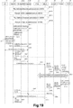
次に、図19を参照して、第1の実施形態に係る処理の流れを説明する。図19は、第1の実施形態に係る処理の概略的な流れの例を示すシーケンス図である。<3.5. Process flow>
Next, with reference to FIG. 19, the flow of processing according to the first embodiment will be described. FIG. 19 is a sequence diagram illustrating an example of a schematic flow of processing according to the first embodiment.
この例では、eNB100がUE10のためのMeNBとして動作している場合に、UE10のためのSeNBが、eNB200A(ソースSeNB)からeNB200B(ターゲットSeNB)に変更される。よって、ここでは、eNB100、eNB200A及びeNB200Bは、それぞれMeNB100、S−SeNB200A及びT−SeNB200Bと表記される。
In this example, when the
(S401)
まず、eNB間でのX2リンクが確立される。とりわけ、MeNB100とT−SeNB200Bとの間でX2リンクが確立される。(S401)
First, an X2 link is established between eNBs. In particular, an X2 link is established between the
3GPP TS36.300 V13.0.0によれば、X2リンクは、eNB間で直接的に確立され、又は、X2GWを介して間接的に確立される。 According to 3GPP TS36.300 V13.0.0, the X2 link is established directly between eNBs or indirectly via X2GW.
また、X2リンクは、オペレータにより手動で確立されることも可能である。あるいは、X2リンクは、3GPP TS36.300の22章で定められているSON(Self-Organization Network)により自動的に確立されることも可能である。SONは、ネットワークの自動最適化アルゴリズムである。
The X2 link can also be established manually by an operator. Alternatively, the X2 link can be automatically established by a SON (Self-Organization Network) defined in
以上の点を考慮すると、X2リンクを確立する4つの手法が存在する。
(A)3GPP TS36.300 V13.0.0の22.3.6章に定められているTNL address discoveryにより、自動でeNB間に直接的にX2リンクを確立する手法(S401A)
(B)手動でeNB間に直接的にX2リンクを確立する手法(S401B)
(C)3GPP TS36.300 V13.0.0の4.6.6.1章に定められているEnhanced TNL address discoveryにより、自動でeNB間にX2GWを介して間接的にX2リンクを確立する手法(S401C)
(D)手動でeNB間にX2GWを介して間接的にX2リンクを確立する手法(S401D)Considering the above points, there are four methods for establishing the X2 link.
(A) A method of automatically establishing an X2 link directly between eNBs by TNL address discovery defined in Chapter 22.3.6 of 3GPP TS36.300 V13.0.0 (S401A)
(B) Method of manually establishing X2 link directly between eNBs (S401B)
(C) A method of automatically establishing an X2 link between eNBs indirectly via X2GW by Enhanced TNL address discovery defined in Section 4.6.6.1 of 3GPP TS36.300 V13.0.0 (S401C)
(D) Method of manually establishing an X2 link between eNBs indirectly via X2GW (S401D)
上述した4つの手法(A〜D)では、MeNB100及びT−SeNB200Bのいずれも、X2リンクを確立する処理を開始できるが、ここではMeNB100が当該処理を開始するものとする。また、MeNB100とS−SeNB200Aとの間のX2リンク、及び、S−SeNB200AとT−SeNB200Bとの間のX2リンクも、上述した4つの手法のいずれかで確立されるが、ここでは説明を省略する。
In the four methods (A to D) described above, both the
−S401A
TNL address discoveryを実行する契機が発生すると、MeNB100は、3GPP TS36.413 V13.0.0に定義されているS1AP:ENB CONFIGURATION TRANSFERメッセージをMME300へ送信する。S1AP:ENB CONFIGURATION TRANSFERメッセージは、SON Configuration Transfer IEを含み、SON Configuration Transfer IEは、X2 TNL Configuration Info IE(図13を参照)を含む。さらに、X2 TNL Configuration Info IEは、Tunnel Information for BBF IE(図14を参照)を含む。例えば、Tunnel Information for BBF IEは、MeNB100のローカルIPアドレス(即ち、パブリックIPアドレス又はグローバルIPアドレス)及びUDPポート番号を含む。-S401A
When an opportunity to execute the TNL address discovery occurs, the
MME300は、S1AP:ENB CONFIGURATION TRANSFERメッセージの受信に応じて、S1AP:MME CONFIGURATION TRANSFERメッセージをT−SeNB200Bへ送信する。S1AP:MME CONFIGURATION TRANSFERメッセージは、S1AP:ENB CONFIGURATION TRANSFERメッセージに含まれていたSON Configuration Transfer IEを含む。即ち、SON Configuration Transfer IEが、MME300を介してMeNB100からT−SeNB200Bへ送信される。これにより、T−SeNB200Bは、MeNB100のローカルIPアドレス及びUDPポート番号を知ることが可能になる。
In response to the reception of the S1AP: ENB CONFIGURATION TRANSFER message, the
さらに、T−SeNB200Bは、S1AP:ENB CONFIGURATION TRANSFERメッセージをMME300へ送信する。S1AP:ENB CONFIGURATION TRANSFERメッセージは、上述したような情報要素(IE)を含むが、ここではT−SeNBのローカルIPアドレス及びUDPポート番号を含む。 Furthermore, T-SeNB200B transmits S1AP: ENB CONFIGURATION TRANSFER message to MME300. The S1AP: ENB CONFIGURATION TRANSFER message includes the information element (IE) as described above, but here includes the local IP address and UDP port number of the T-SeNB.
MME300は、S1AP:ENB CONFIGURATION TRANSFERメッセージの受信に応じて、S1AP:MME CONFIGURATION TRANSFERメッセージをMeNB100へ送信する。S1AP:MME CONFIGURATION TRANSFERメッセージは、S1AP:ENB CONFIGURATION TRANSFERメッセージに含まれていたSON Configuration Transfer IEを含む。即ち、SON Configuration Transfer IEが、MME300を介してT−SeNB200BからMeNB100Bへ送信される。これにより、MeNB100は、T−SeNB200BのローカルIPアドレス及びUDPポート番号を知ることが可能になる。
In response to the reception of the S1AP: ENB CONFIGURATION TRANSFER message, the
−S401B
MeNB100は、オペレータによる設定(例えば、(宛先としての)T−SeNB200BのローカルIPアドレス及びUDPポート番号の設定)に基づいて、3GPP TS36.423 V13.0.0に定義されているX2AP:X2 SETUP REQUESTメッセージ(図15を参照)をT−SeNB200Bへ送信する。X2AP:X2 SETUP REQUESTメッセージは、MeNBのローカルIPアドレス及びUDPポート番号を含む。これにより、T−SeNB200Bは、MeNB100のローカルIPアドレス及びUDPポート番号を知ることが可能になる。-S401B
The
T−SeNB200Bは、3GPP TS36.423 V13.0.0に定義されているX2AP:X2 SETUP RESPONSEメッセージ(図16を参照)をMeNB100へ送信する。X2AP:X2 SETUP RESPONSEメッセージは、T−SeNB200BのローカルIPアドレス及びUDPポート番号を含む。これにより、MeNB100は、T−SeNB200BのローカルIPアドレス及びUDPポート番号を知ることが可能になる。
The T-SeNB 200B transmits to the
なお、上述した処理とは反対に、T−SeNB200Bが、X2AP:X2 SETUP REQUESTメッセージ(図15を参照)をMeNB100へ送信し、MeNB100が、X2AP:X2 SETUP RESPONSEメッセージ(図16を参照)をT−SeNB200Bへ送信してもよい。
In contrast to the above-described processing, the T-SeNB 200B transmits an X2AP: X2 SETUP REQUEST message (see FIG. 15) to the
−S401C
ステップS401Cは、MeNB100とX2GWとの間のX2APメッセージの処理、及びX2GWとT−SeNB200Bとの間のX2APメッセージの処理(即ち、3GPP TS36.300 V13.0.0の22.3.6.1章の手続きに追加された処理)を除き、ステップS401Aと同じである。よって、ここでは重複する説明を省略する。-S401C
Step S401C is processing of X2AP message between MeNB100 and X2GW, and processing of X2AP message between X2GW and T-SeNB200B (namely, 22.36.1 of 3GPP TS36.300 V13.0.0). Except for the processing added to the chapter procedure). Therefore, the overlapping description is omitted here.
−S401D
MeNB100は、3GPP TS36.423 V13.0.0に定義されているX2AP:X2AP MESSAGE TRANSFERメッセージをX2GW(T−SeNB200B)へ送信する。X2AP MESSAGE TRANSFERメッセージは、X2AP:X2 SETUP REQUESTメッセージ(図15を参照)を含む。即ち、MeNB100は、X2GWを介して、X2AP:X2 SETUP REQUESTメッセージをT−SeNB200Bへ送信する。X2AP:X2 SETUP REQUESTメッセージは、MeNB100のローカルIPアドレス及びUDPポート番号を含む。これにより、T−SeNB200Bは、MeNB100のローカルIPアドレス及びUDPポート番号を知ることが可能になる。-S401D
MeNB100 transmits X2AP: X2AP MESSAGE TRANSFER message defined in 3GPP TS36.423 V13.0.0 to X2GW (T-SeNB200B). The X2AP MESSAGE TRANSFER message includes an X2AP: X2 SETUP REQUEST message (see FIG. 15). That is, MeNB100 transmits X2AP: X2 SETUP REQUEST message to T-SeNB200B via X2GW. The X2AP: X2 SETUP REQUEST message includes the local IP address and UDP port number of the
T−SeNB200Bは、3GPP TS36.423 V13.0.0に定義されているX2AP:X2AP MESSAGE TRANSFERメッセージをX2GW(MeNB100)へ送信する。X2AP MESSAGE TRANSFERメッセージは、X2AP:X2 SETUP RESPONSEメッセージ(図16を参照)を含む。即ち、T−SeNB200Bは、X2GWを介して、X2AP:X2 SETUP RESPONSEメッセージをMeNB100へ送信する。X2AP:X2 SETUP RESPONSEメッセージは、T−SeNB200BのローカルIPアドレス及びUDPポート番号を含む。これにより、MeNB100は、T−SeNB200BのローカルIPアドレス及びUDPポート番号を知ることが可能になる。 T-SeNB200B transmits X2AP: X2AP MESSAGE TRANSFER message defined in 3GPP TS36.423 V13.0.0 to X2GW (MeNB100). The X2AP MESSAGE TRANSFER message includes an X2AP: X2 SETUP RESPONSE message (see FIG. 16). That is, T-SeNB200B transmits X2AP: X2 SETUP RESPONSE message to MeNB100 via X2GW. The X2AP: X2 SETUP RESPONSE message includes the local IP address and UDP port number of the T-SeNB 200B. Thereby, MeNB100 becomes possible to know the local IP address and UDP port number of T-SeNB200B.
なお、上述した処理とは反対に、T−SeNB200Bが、X2AP:X2 SETUP REQUESTメッセージ(図15を参照)をMeNB100へ送信し、MeNB100が、X2AP:X2 SETUP RESPONSEメッセージ(図16を参照)をT−SeNB200Bへ送信してもよい。
In contrast to the above-described processing, the T-SeNB 200B transmits an X2AP: X2 SETUP REQUEST message (see FIG. 15) to the
−補足
ステップS401の完了後のいずれかのタイミングで、UE10のデュアルコネクティビティが開始される。より具体的には、UE10は、MeNB100及びS−SeNB200Aの両方と通信し始める。-Supplement The dual connectivity of UE10 is started in any timing after completion of step S401. More specifically, the
(S411)
MeNB100は、X2AP:SENB ADDITION REQUESTメッセージをT−SeNB200Bへ送信する。これにより、MeNB00は、UE10のためのリソースの割当てをT−SeNB200Bに要求する。(S411)
MeNB100 transmits X2AP: SENB ADDITION REQUEST message to T-SeNB200B. Thereby, MeNB00 requests | requires allocation of the resource for UE10 to T-SeNB200B.
(S413)
T−SeNB200Bは、X2AP:SENB ADDITION REQUEST ACKNOWLEDGEメッセージをMeNB100へ送信する。これにより、T−SeNB200Bは、UE10のためのリソースを割り当てたことをMeNB100に通知する。(S413)
T-SeNB200B transmits X2AP: SENB ADDITION REQUEST ACKNOWLEDGE message to MeNB100. Thereby, T-SeNB200B notifies MeNB100 that the resource for UE10 was allocated.
なお、X2AP:SENB ADDITION REQUEST ACKNOWLEDGEメッセージは、図17に示されるような情報要素を含んでもよく、とりわけTunnel Information for BBF IEを含んでもよい。さらに、Tunnel Information for BBF IEは、図14に示されるような情報要素を含んでもよい。 Note that the X2AP: SENB ADDITION REQUEST ACKNOWLEDGE message may include an information element as shown in FIG. 17, and may include a Tunnel Information for BBF IE, among others. Furthermore, the Tunnel Information for BBF IE may include an information element as shown in FIG.
(S415)
MeNB100は、X2AP:SENB RELEASE REQUESTメッセージをS−SeNB200Aへ送信する。これにより、S−SeNB200Aは、UE10のためのリソースを解放する。(S415)
MeNB100 transmits a X2AP: SENB RELEASE REQUEST message to S-SeNB200A. Thereby, S-SeNB200A releases the resource for UE10.
(S417)
MeNB10は、新たなコンフィギュレーションを適用するようにUE10に指示する。(S417)
The
(S419)
UE10は、新たなコンフィギュレーションを適用したことをMeNB100に通知する。(S419)
The
(S421)
MeNB100は、X2AP:SENB RECONFIGURATION COMPLETEメッセージをT−SeNB200Bへ送信する。これにより、MeNB100は、RRC connection reconfiguration手続きの成功をT−SeNB200Bに通知する。(S421)
MeNB100 transmits X2AP: SENB RECONFIGURATION COMPLETE message to T-SeNB200B. Thereby, MeNB100 notifies T-SeNB200B of the success of a RRC connection reconfiguration procedure.
(S423)
UE10は、T−SeNB200Bと同期をとる。(S423)
UE10 synchronizes with T-SeNB200B.
(S425−S429)
S−SeNB200AからT−SeNB200Bへデータが転送される。(S425-S429)
Data is transferred from the S-
(S431)
−SCGベアラがあるケース
UE10及びS−SeNB200AについてのSCGベアラがある場合に(即ち、SCGベアラオプションが設定されている場合に)、MeNB100は、S1AP:E−RAB MODIFICATION INDICATIONメッセージ(図11を参照)をMME300へ送信する。(S431)
-When there is an SCG bearer When there is an SCG bearer for the
S1AP:E−RAB MODIFICATION INDICATIONメッセージは、Tunnel Information for BBF IEを含む。さらに、Tunnel Information for BBF IEは、T−SeNB200BのローカルIPアドレス及びUDPポート番号を含む。 S1AP: E-RAB MODIFICATION INDICATION message includes Tunnel Information for BBF IE. Furthermore, Tunnel Information for BBF IE includes the local IP address and UDP port number of T-SeNB 200B.
−SCGベアラがないケース(スプリットベアラのみがあるケース)
UE10及びS−SeNB200AについてのSCGベアラはなく、スプリットベアラのみがある場合には(即ち、SCGベアラオプションが設定されていない場合には)、3GPP TS36.300 v13.0.0によれば、MeNB100は、S1AP:E−RAB MODIFICATION INDICATIONメッセージをMME300へ送信しない。しかし、第1の実施形態では、例えば、MeNB100は、S1AP:E−RAB MODIFICATION INDICATIONメッセージをMME300へ送信する。-Case without SCG bearer (case with split bearer only)
If there is no SCG bearer for
S1AP:E−RAB MODIFICATION INDICATIONメッセージは、Tunnel Information for BBF IEを含む。さらに、Tunnel Information for BBF IEは、T−SeNB200BのローカルIPアドレス及びUDPポート番号を含む。 S1AP: E-RAB MODIFICATION INDICATION message includes Tunnel Information for BBF IE. Furthermore, Tunnel Information for BBF IE includes the local IP address and UDP port number of T-SeNB 200B.
(S433)
第1の実施形態では、UE10及びS−SeNB200AについてのSCGベアラの有無によらず、MME100は、MODIFY BEARER REQUESTメッセージをS−GW20へ送信する。(S433)
In 1st Embodiment, MME100 transmits a MODIFY BEARER REQUEST message to S-GW20 irrespective of the presence or absence of the SCG bearer about UE10 and S-SeNB200A.
なお、S−GW20は、上記SCGベアラがある場合には、データパスの更新を行い、上記SCGベアラがない場合には(即ち、スプリットベアラのみがある場合には)、データパスの更新を行わない。
The S-
(S435)
S−GW20は、Modify Bearer Requestメッセージ(T−SeNB200BのローカルIPアドレス及びUDPポート番号を含む)をP−GW30へ送信する。(S435)
The S-
(S437)
P−GW30は、IP−CAN session modification requestメッセージ(T−SeNB200BのローカルIPアドレス及びUDPポート番号を含む)をPCRF40へ送信する。(S437)
The P-
(S439)
PCRF40は、FBA50との間でGateway control and QoS Rule provisioning手続き(T−SeNB200BのローカルIPアドレス及びUDPポート番号の送受信を含む)を実行する。FBA50は、PCRF40から受信したT−SeNB200BのローカルIPアドレス及びUDPポート番号に対応する回線に、DSCPに変換されたQoS情報を適用する。(S439)
The
例えば、FBA50は、T−SeNB200Bが接続される回線についての帯域制御を行う。一例として、上記回線について、図1に示されるように、3GPPシステムの利用者が使用している基地局のために確保している帯域(帯域93)の上限値が調整され得る。別の例として、上記回線について、図2に示されるように、3GPPシステムの利用者を新たに受け入れ可能な帯域(帯域95)が減らされ得る。
For example, the
これにより、3GPPシステムの利用者の通信品質の維持/向上、及び/又は、基地局毎のRABの収容数の適正化が可能になる。 This makes it possible to maintain / improve the communication quality of users of the 3GPP system and / or optimize the number of RABs accommodated for each base station.
なお、FBA50が行う処理は、例えば、Broadband forumのTR−203及び/又はTR−134等の勧告に従う。
Note that the processing performed by the
(S441)
PCRF40は、IP−CAN session modification AcknowledgeメッセージをP−GW30へ送信する。(S441)
The
(S443)
P−GW30は、Modify Bearer ResponseをS−GW20へ送信する。(S443)
The P-
(S445)
S−GW20は、Modify Bearer ResponseメッセージをMME300へ送信する。(S445)
The S-
(S447−S449)
SCGベアラがある場合には、データパスの更新のための処理が行われる。SCGベアラがない場合には、当該処理は実行されない。(S447-S449)
If there is an SCG bearer, a process for updating the data path is performed. If there is no SCG bearer, the process is not executed.
(S451)
MME300は、S1AP:E−RAB MODIFICATION CONFIRMメッセージをMeNB100へ送信する。(S451)
MME300 transmits S1AP: E-RAB MODIFICATION CONFIRM message to MeNB100.
(S453)
MeNB100は、X2AP:UE CONTEXT RELEASEメッセージをS−SeNB200Aへ送信する。これにより、S−SeNB200Aは、UEコンテキストを解放する。(S453)
The
以上、第1の実施形態に係る処理の概略的な流れの例を説明した。上述した例では、ステップS445の後にステップS447が実行されるが、ステップS447は、ステップS433の後の任意のタイミングで実行され得る。 Heretofore, an example of a schematic flow of processing according to the first embodiment has been described. In the example described above, step S447 is executed after step S445, but step S447 may be executed at any timing after step S433.
第1の実施形態の上述した例では、Tunnel Information for BBF IEを新たな情報要素として含むX2AP:SETUP REQUESTメッセージ、X2AP:X2 SETUP RESPONSEメッセージ、X2AP:SENB ADDITION REQUEST ACKNOWLEDGEメッセージ、S1AP:ENB CONFIGURATION TRANSFERメッセージ、S1AP:MME CONFIGURATION TRANSFERメッセージ、及び、S1AP:E−RAB MODIFICATION INDICATIONメッセージが使用される。しかし、これらのメッセージは例示にすぎず、IPアドレス及びUDPポート番号(例えば、Tunnel Information for BBF IE)を含む他のメッセージが使用されてもよい。 In the above-described example of the first embodiment, X2AP: SETUP REQUEST message, X2AP: SENB ADDITION REQUEST ACKNOWLEDGE message SUN, including the Tunnel Information for BBF IE as a new information element, X2AP: X2 SETUP RESPONSE ACKNOWLEDGE message S , S1AP: MME CONFIGURATION TRANSFER message and S1AP: E-RAB MODIFICATION INDICATION message. However, these messages are exemplary only, and other messages including an IP address and a UDP port number (eg, Tunnel Information for BBF IE) may be used.
<3.6.変形例>
続いて、図20を参照して、第1の実施形態の変形例を説明する。<3.6. Modification>
Subsequently, a modification of the first embodiment will be described with reference to FIG.
(1)第1の変形例
ネットワークノード(例えば、eNB100、eNB200、MME300、S−GW20、P−GW30及び/又はPCRF40)は、個別のハードウェアで構成されるのではなく、VNF(Virtualized Network Function)として仮想マシン上で動作してもよい。即ち、NFV(Network Function Virtualization)が使用されてもよい。仮想マシン上でVFNとして動作するネットワークノードは、MANO(Management and Orchestration)と呼ばれる機能により管理及び編成されてもよい。(1) First Modification A network node (e.g.,
例えば、セルラーネットワークのネットワークノード(例えば、eNB100、eNB200、MME300、S−GW20、P−GW30及び/又はPCRF40)のVNFを管理するMANOが、FBA50の構成要素であるSDN(Software-Defined Network)コントローラも管理する。この場合には、FBA50の帯域制御は、VFNであるPCRF50ではなく、MANOにより行われてもよい。
For example, an SDN (Software-Defined Network) controller in which MANO that manages the VNF of a network node (for example,
(2)第2の変形例
PCRF40に相当する機能が、RAN(Radio Access Network)に存在してもよい。この場合に、PCRF40ではなく、RANが、固定ブロードバンドアクセスネットワーク(FBA50)の制御(例えば、帯域制御)を行ってもよい。(2) Second Modification A function corresponding to the
この場合に、eNB100は、MME300ではなく、上記機能を有するノードへ、上記第1のメッセージを送信してもよい。あるいは、MME300は、S−GW20ではなく、上記機能を有するノードへ、上記第2のメッセージを送信してもよい。
In this case, the
(3)第3の変形例
例えば、3GPP R2−153972において、LTE−WLAN(Wireless Local Area Network)アグリゲーション(LWA)が提案されている。LWAでは、UEは、LTEとWLANの両方を使用して通信する。(3) Third Modification For example, in 3GPP R2-153972, LTE-WLAN (Wireless Local Area Network) aggregation (LWA) is proposed. In LWA, the UE communicates using both LTE and WLAN.
LWAのケースでは、LTEのみでデータが送信されるMCGベアラ、LTE及びWLANの両方でデータが送信されるスプリットベアラ、及び、WLANのみでデータが送信されるスイッチトベアラ(Switched bearer)がある。スプリットベアラ又はスイッチトベアラが使用される場合には、eNBは、Xwインターフェースを介してデータをWLANへ送信される。 In the case of LWA, there are an MCG bearer in which data is transmitted only in LTE, a split bearer in which data is transmitted in both LTE and WLAN, and a switched bearer in which data is transmitted only in WLAN. When a split bearer or a switched bearer is used, the eNB transmits data to the WLAN via the Xw interface.
XwインターフェースがFBA50(又はPCRF40に接続される他のネットワーク)を介する場合には、第1の実施形態の上述した例(即ち、デュアルコネクティビティの例)と同様の手法が、LWAのケースにも適用されてもよい。これにより、3GPPシステムの利用者の通信品質の維持/向上、及び/又は、基地局毎のUEの収容数の適正化が可能になり得る。 When the Xw interface is through the FBA 50 (or another network connected to the PCRF 40), the same method as the above-described example of the first embodiment (that is, the example of dual connectivity) is also applied to the LWA case. May be. Thereby, it is possible to maintain / improve the communication quality of users of the 3GPP system and / or optimize the number of UEs accommodated for each base station.
(a)システムの構成例
図20は、第1の実施形態の第3の変形例に係るシステムの概略的な構成の一例を示す説明図である。図20を参照すると、当該システムは、eNB100、WLAN Termination(WT)201A、WT201B、WLAN AP203A、WLAN AP203B、及びMME300を含む。さらに、上記システムは、UE10、S−GW20、P−GW30、PCRF40及びFBA50を含む。(A) System Configuration Example FIG. 20 is an explanatory diagram illustrating an example of a schematic configuration of a system according to a third modification of the first embodiment. Referring to FIG. 20, the system includes
WT201A及びWT201Bの区別が必要ない場合には、WT201A及びWT201Bの各々は、単にWT201と呼ばれ得る。同様に、WLAN AP203A及びWLAN AP203Bの区別が必要ない場合には、WLAN AP203A及びWLAN AP203Bの各々は、単にWLAN AP203と呼ばれ得る。
If there is no need to distinguish between
例えば、WT201は、Xwインターフェースを終端する。 For example, the WT 201 terminates the Xw interface.
例えば、WLAN AP203は、WLANモビリティセット(即ち、1つ以上のWLAN APのセット)に属する。当該WLANモビリティセットは、共通のWT201を共有する。例えば、WLAN AP203Aは、第1のWLANモビリティセットに属し、当該第1のWLANモビリティセットは、WT201Aを共有する。例えば、WLAN AP203Bは、第2のWLANモビリティセットに属し、当該第2のWLANモビリティセットは、WT201Bを共有する。
For example, the WLAN AP 203 belongs to a WLAN mobility set (ie, a set of one or more WLAN APs). The WLAN mobility set shares a common WT 201. For example, the
UE10は、LWAをサポートし、eNB100及びWLAN AP203と通信可能である。とりわけこの例では、まず、UE10は、LWAで、eNB100及びWLAN AP203Aと通信している。その後、例えば、UE10の移動に伴い、UE10が通信するAPが、WLAN AP203A(S−AP)からWLAN AP203B(T−AP)に変更される。その結果、UE10は、eNB100及びWLAN AP203Bと通信するようになる。
UE10 supports LWA and can communicate with eNB100 and WLAN AP203. In particular, in this example, first, the
(b)技術的特徴
例えば、eNB100が通信するUE10と通信するWLAN AP(即ち、LTE−WLANアグリゲーションのWLAN AP)が、WLAN AP203AからWLAN AP203Bに変更される。この場合に、eNB100(第2通信処理部143)は、WLAN AP203Bのアドレス情報及びトランスポート識別情報を含む第1のメッセージを、コアネットワークノード(例えば、MME300)へ送信する。例えば、eNB100(生成部145)は、上記第1のメッセージを生成する。(B) Technical features For example, the WLAN AP that communicates with the
例えば、MME300(通信処理部331)は、上記第1のメッセージをeNB100から受信する。そして、MME300(通信処理部331)は、上記アドレス情報及び上記トランスポート識別情報を含む第2のメッセージを、コアネットワークノード(例えば、S−GW20)へ送信する。例えば、MME300(生成部333)は、上記第2のメッセージを生成する。
For example, the MME 300 (communication processing unit 331) receives the first message from the
例えば、WLAN AP203B(通信処理部)は、WLAN AP203Bのアドレス情報及びトランスポート識別情報を含む第3のメッセージを、(例えばWT201Bを介して)eNB100へ送信する。例えば、WLAN AP203B(生成部)は、上記第3のメッセージを生成する。あるいは、WT201B(通信処理部)が、WLAN AP203Bのアドレス情報及びトランスポート識別情報を含む第3のメッセージを、eNB100へ送信してもよい。例えば、WT201B(生成部)が、上記第3のメッセージを生成してもよい。 For example, the WLAN AP 203B (communication processing unit) transmits a third message including the address information and transport identification information of the WLAN AP 203B to the eNB 100 (for example, via the WT 201B). For example, the WLAN AP 203B (generation unit) generates the third message. Or WT201B (communication processing part) may transmit the 3rd message containing the address information and transport identification information of WLAN AP203B to eNB100. For example, the WT 201B (generation unit) may generate the third message.
これにより、例えば、LTE−WLANアグリゲーションのケース(具体的には、WLAN APの変更のケース)においても固定ブロードバンドアクセスネットワークの制御に必要な情報をコアネットワークノードが取得することが可能になる。その結果、3GPPシステムの利用者の通信品質が維持/向上され、基地局毎のRABの収容数が適正化され得る。 Thereby, for example, even in the case of LTE-WLAN aggregation (specifically, the case of changing the WLAN AP), the core network node can acquire information necessary for controlling the fixed broadband access network. As a result, communication quality of users of the 3GPP system can be maintained / improved, and the number of RABs accommodated for each base station can be optimized.
<<4.第2の実施形態>>
続いて、図21〜図25を参照して、本発明の第2の実施形態を説明する。<< 4. Second Embodiment >>
Subsequently, a second embodiment of the present invention will be described with reference to FIGS.
<4.1.システムの構成例>
図21を参照して、第2の実施形態に係るシステム2の構成の例を説明する。図21は、第2の実施形態に係るシステム2の概略的な構成の一例を示す説明図である。図21を参照すると、システム2は、端末装置11、基地局500、無線通信装置600A、無線通信装置600B、第1コアネットワークノード700及び第2コアネットワークノード60を含む。なお、無線通信装置600A及び無線通信装置600Bの区別が必要ない場合には、無線通信装置600A及び無線通信装置600Bの各々は、単に無線通信装置600と呼ばれ得る。<4.1. System configuration example>
An example of the configuration of the
例えば、端末装置11はUEであり、基地局500はeNBであり、第1コアネットワークノード700はMMEであり、第2コアネットワークノード60はS−GWである。
For example, the
とりわけ、端末装置11は、基地局500及び無線通信装置600と通信可能である。換言すると、無線通信装置600は、基地局500が通信する端末装置11と通信可能である。
In particular, the
例えば、端末装置11の移動に伴い、基地局500が通信する端末装置11と通信する無線通信装置が、無線通信装置600Aから無線通信装置600Bに変更され得る。
For example, as the
(1)第1のケース
例えば、端末装置11は、デュアルコネクティビティをサポートする。(1) First Case For example, the
例えば、無線通信装置600は、デュアルコネクティビティにおいて追加の無線リソースを端末装置11に提供するセカンダリ基地局として動作可能な基地局である。具体的には、例えば、無線通信装置600は、SeNBとして動作可能なeNBである。一例として、無線通信装置600は、ホームeNBであるが、この例に限定されない。
For example, the
例えば、基地局500は、上記セカンダリ基地局に対応するマスタ基地局として動作可能である。具体的には、例えば、基地局500は、MeNBとして動作可能なeNBである。
For example, the
例えば、端末装置11の移動に伴い、端末装置11のためのセカンダリ基地局が、無線通信装置600Aから無線通信装置600Bに変更され得る。
For example, as the
(2)第2のケース
端末装置11は、異なる無線アクセス技術のアグリゲーションをサポートしてもよい。当該アグリゲーションは、LTE−WLANアグリゲーション(LWA)であってもよい。(2) Second Case The
無線通信装置600は、基地局500とは異なる無線アクセス技術を使用するアクセスポイント(AP)であってもよい。具体的には、無線通信装置600は、WLAN APであってもよい。この場合に、無線通信装置600は、WLAN Termination(WT)を介して基地局500と通信してもよい。
無線通信装置600Aは、第1のモビリティセットに属する第1のAPであってもよく、無線通信装置600Bは、上記第1のモビリティセットとは異なる第2のモビリティセットに属する第2のAPであってもよい。上記第1のモビリティセットは第1のWTを共有してもよく、上記第2のモビリティセットは第2のWTを共有してもよい。
The
端末装置11の移動に伴い、基地局500が通信する端末装置11と通信するAPが、無線通信装置600Aから無線通信装置600Bに変更されてもよい。
As the
<4.2.基地局の構成例>
次に、図22を参照して、第2の実施形態に係る基地局500の構成の例を説明する。図22は、第2の実施形態に係る基地局500の概略的な構成の例を示すブロック図である。図22を参照すると、基地局500は、通信処理部503を備える。通信処理部503は、プロセッサ等により実装され得る。<4.2. Example of base station configuration>
Next, an example of the configuration of the
例えば、基地局500が通信する端末装置11と通信する無線通信装置が、無線通信装置600Aから無線通信装置600Bに変更される。この場合に、基地局500(通信処理部503)は、無線通信装置600Bのアドレス情報及びトランスポート識別情報を含む第1のメッセージを、第1コアネットワークノード700へ送信する。
For example, the wireless communication device that communicates with the
これにより、例えば、より多くのケースにおいて固定ブロードバンドアクセスネットワークの制御に必要な情報をコアネットワークノードが取得することが可能になる。その結果、より多くのケースにおいて、3GPPシステムの利用者の通信品質が維持/向上され、基地局毎のRABの収容数が適正化され得る。 As a result, for example, the core network node can acquire information necessary for controlling the fixed broadband access network in more cases. As a result, in many cases, the communication quality of the user of the 3GPP system is maintained / improved, and the number of RABs accommodated per base station can be optimized.
(1)第1のケース
上述したように、例えば、無線通信装置600は、デュアルコネクティビティにおいて追加の無線リソースを端末装置11に提供するセカンダリ基地局(例えば、SeNB)として動作可能な基地局であり、基地局500は、上記セカンダリ基地局に対応するマスタ基地局(例えば、MeNB)として動作可能である。(1) First Case As described above, for example, the
このケースについての具体的な説明は、例えば、ノード名及び符号等の相違を除き、第1の実施形態における説明と同じである。よって、ここでは重複する説明を省略する。即ち、第1の実施形態において説明されたeNB100の技術的特徴は、基地局500の技術的特徴としても適用され得る。
The specific description of this case is the same as the description in the first embodiment, except for the difference in node name and code, for example. Therefore, the overlapping description is omitted here. That is, the technical features of the
このようなデュアルコネクティビティのケース(具体的には、セカンダリ基地局の変更のケース)においても固定ブロードバンドアクセスネットワークの制御が行われ得る。その結果、3GPPシステムの利用者の通信品質が維持/向上され、基地局毎のRABの収容数が適正化され得る。 In such a dual connectivity case (specifically, a case of changing a secondary base station), the fixed broadband access network can be controlled. As a result, communication quality of users of the 3GPP system can be maintained / improved, and the number of RABs accommodated for each base station can be optimized.
(2)第2のケース
上述したように、無線通信装置600は、基地局500とは異なる無線アクセス技術を使用するAP(例えば、WLAN AP)であってもよい。(2) Second Case As described above, the
このケースについての具体的な説明は、例えば、ノード名及び符号等の相違を除き、第1の実施形態の第3の変形例における説明と同じである。よって、ここでは重複する説明を省略する。即ち、第1の実施形態の第3の変形例において説明されたeNB100の技術的特徴は、基地局500の技術的特徴としても適用され得る。
A specific description of this case is the same as the description in the third modification of the first embodiment, except for the difference in node name and code, for example. Therefore, the overlapping description is omitted here. That is, the technical features of the
このような異なる無線アクセス技術のアグリゲーション(例えば、LTE−WLANアグリゲーション)のケース(例えば、WLAN APの変更のケース)においても固定ブロードバンドアクセスネットワークの制御が行われ得る。その結果、3GPPシステムの利用者の通信品質が維持/向上され、基地局毎のRABの収容数が適正化され得る。 The fixed broadband access network can also be controlled in such a case of aggregation of different radio access technologies (for example, LTE-WLAN aggregation) (for example, a case of changing WLAN AP). As a result, communication quality of users of the 3GPP system can be maintained / improved, and the number of RABs accommodated for each base station can be optimized.
<4.3.無線通信装置の構成例>
次に、図23を参照して、第2の実施形態に係る無線通信装置600の構成の例を説明する。図23は、第2の実施形態に係る無線通信装置600の概略的な構成の例を示すブロック図である。図23を参照すると、無線通信装置600は、通信処理部603を備える。通信処理部603は、プロセッサ等により実装され得る。<4.3. Configuration example of wireless communication device>
Next, an exemplary configuration of the
無線通信装置600(通信処理部603)は、無線通信装置600のアドレス情報及びトランスポート識別情報を含むメッセージを、例えば基地局500へ送信する。あるいは、無線通信装置600(通信処理部603)は、上記アドレス情報及び上記トランスポート識別情報を基地局500へ転送するコアネットワークノード(例えば、第1コアネットワークノード700)へ、上記メッセージを送信してもよい。
Radio communication apparatus 600 (communication processing unit 603) transmits a message including address information and transport identification information of
これにより、例えば、基地局500が無線通信装置600のアドレス情報及びトランスポート識別情報を知ることが可能になる。その結果、固定ブロードバンドアクセスネットワークの制御が行われ得る。
Thereby, for example, the
(1)第1のケース
上述したように、例えば、無線通信装置600は、デュアルコネクティビティにおいて追加の無線リソースを端末装置11に提供するセカンダリ基地局(例えば、SeNB)として動作可能な基地局であり、基地局500は、上記セカンダリ基地局に対応するマスタ基地局(例えば、MeNB)として動作可能である。(1) First Case As described above, for example, the
このケースについての具体的な説明は、例えば、ノード名及び符号等の相違を除き、第1の実施形態における説明と同じである。よって、ここでは重複する説明を省略する。即ち、第1の実施形態において説明されたeNB200の技術的特徴は、無線通信装置600の技術的特徴としても適用され得る。
The specific description of this case is the same as the description in the first embodiment, except for the difference in node name and code, for example. Therefore, the overlapping description is omitted here. That is, the technical features of the
(2)第2のケース
上述したように、無線通信装置600は、基地局500とは異なる無線アクセス技術を使用するAP(例えば、WLAN AP)であってもよい。(2) Second Case As described above, the
このケースについての具体的な説明は、例えば、ノード名及び符号等の相違を除き、第1の実施形態の第3の変形例における説明と同じである。よって、ここでは重複する説明を省略する。即ち、第1の実施形態の第3の変形例において説明されたWLAN AP203の技術的特徴は、無線通信装置600の技術的特徴としても適用され得る。
A specific description of this case is the same as the description in the third modification of the first embodiment, except for the difference in node name and code, for example. Therefore, the overlapping description is omitted here. That is, the technical feature of the WLAN AP 203 described in the third modification of the first embodiment can be applied as the technical feature of the
<4.4.第1コアネットワークノードの構成例>
次に、図24を参照して、第2の実施形態に係る第1コアネットワークノード700の構成の例を説明する。図24は、第2の実施形態に係る第1コアネットワークノード700の概略的な構成の例を示すブロック図である。図24を参照すると、第1コアネットワークノード700は、通信処理部701を備える。通信処理部701は、プロセッサ等により実装され得る。<4.4. Configuration example of first core network node>
Next, an example of the configuration of the first
例えば、基地局500が通信する端末装置11と通信する無線通信装置が、無線通信装置600Aから無線通信装置600Bに変更される。この場合に、第1コアネットワークノード700(通信処理部701)は、無線通信装置600Bのアドレス情報及びトランスポート識別情報を含む第1のメッセージを、基地局500から受信する。そして、第1コアネットワークノード700(通信処理部701)は、上記アドレス情報及び上記トランスポート識別情報を含む第2のメッセージを、第2コアネットワークノード60へ送信する。
For example, the wireless communication device that communicates with the
これにより、例えば、より多くのケースにおいて固定ブロードバンドアクセスネットワークの制御に必要な情報をコアネットワークノードが取得することが可能になる。その結果、より多くのケースにおいて、3GPPシステムの利用者の通信品質が維持/向上され、基地局毎のRABの収容数が適正化され得る。 As a result, for example, the core network node can acquire information necessary for controlling the fixed broadband access network in more cases. As a result, in many cases, the communication quality of the user of the 3GPP system is maintained / improved, and the number of RABs accommodated per base station can be optimized.
(1)第1のケース
上述したように、例えば、無線通信装置600は、デュアルコネクティビティにおいて追加の無線リソースを端末装置11に提供するセカンダリ基地局(例えば、SeNB)として動作可能な基地局であり、基地局500は、上記セカンダリ基地局に対応するマスタ基地局(例えば、MeNB)として動作可能である。(1) First Case As described above, for example, the
このケースについての具体的な説明は、例えば、ノード名及び符号等の相違を除き、第1の実施形態における説明と同じである。よって、ここでは重複する説明を省略する。即ち、第1の実施形態において説明されたMME300の技術的特徴は、第1コアネットワークノード700の技術的特徴としても適用され得る。
The specific description of this case is the same as the description in the first embodiment, except for the difference in node name and code, for example. Therefore, the overlapping description is omitted here. That is, the technical features of the
このようなデュアルコネクティビティのケース(具体的には、セカンダリ基地局の変更のケース)においても固定ブロードバンドアクセスネットワークの制御が行われ得る。その結果、3GPPシステムの利用者の通信品質が維持/向上され、基地局毎のRABの収容数が適正化され得る。 In such a dual connectivity case (specifically, a case of changing a secondary base station), the fixed broadband access network can be controlled. As a result, communication quality of users of the 3GPP system can be maintained / improved, and the number of RABs accommodated for each base station can be optimized.
(2)第2のケース
上述したように、無線通信装置600は、基地局500とは異なる無線アクセス技術を使用するAP(例えば、WLAN AP)であってもよい。(2) Second Case As described above, the
このケースについての具体的な説明は、例えば、ノード名及び符号等の相違を除き、第1の実施形態の第3の変形例における説明と同じである。よって、ここでは重複する説明を省略する。即ち、第1の実施形態の第3の変形例において説明されたMME300の技術的特徴は、第1コアネットワークノード700の技術的特徴としても適用され得る。
A specific description of this case is the same as the description in the third modification of the first embodiment, except for the difference in node name and code, for example. Therefore, the overlapping description is omitted here. That is, the technical feature of the
このような異なる無線アクセス技術のアグリゲーション(例えば、LTE−WLANアグリゲーション)のケース(具体的には、アクセスポイントの変更のケース)においても固定ブロードバンドアクセスネットワークの制御が行われ得る。その結果、3GPPシステムの利用者の通信品質が維持/向上され、基地局毎のRABの収容数が適正化され得る。 The fixed broadband access network can also be controlled in such a case of aggregation of different radio access technologies (for example, LTE-WLAN aggregation) (specifically, a case of changing an access point). As a result, communication quality of users of the 3GPP system can be maintained / improved, and the number of RABs accommodated for each base station can be optimized.
<4.5.処理の流れ>
次に、図25を参照して、第2の実施形態に係る処理の流れを説明する。図25は、第2の実施形態に係る処理の概略的な流れの例を示すシーケンス図である。<4.5. Process flow>
Next, the flow of processing according to the second embodiment will be described with reference to FIG. FIG. 25 is a sequence diagram illustrating an example of a schematic flow of processing according to the second embodiment.
(S801)
無線通信装置600は、無線通信装置600のアドレス情報及びトランスポート識別情報を含むメッセージを、基地局500へ送信する。(S801)
(S803)
基地局500が通信する端末装置11と通信する無線通信装置が、無線通信装置600Aから無線通信装置600Bに変更される。この場合に、基地局500は、無線通信装置600Bのアドレス情報及びトランスポート識別情報を含む第1のメッセージを、第1コアネットワークノード700へ送信する。第1コアネットワークノード700は、当該第1のメッセージを基地局500から受信する。(S803)
The wireless communication device that communicates with the
(S805)
例えば、第1コアネットワークノード700は、上記アドレス情報及び上記トランスポート識別情報を含む第2のメッセージを、第2コアネットワークノード60へ送信する。(S805)
For example, the first
<4.6.変形例>
第2の実施形態では、例えば上述したように、第2のケースにおいては、無線通信装置600(例えば、WLAN AP)が、無線通信装置600のアドレス情報及びトランスポート識別情報を含むメッセージを、基地局500へ送信する。<4.6. Modification>
In the second embodiment, for example, as described above, in the second case, the wireless communication device 600 (for example, WLAN AP) transmits a message including the address information and transport identification information of the
一方、第2の実施形態の変形例として、無線通信装置600(例えば、WLAN AP)ではなく、無線通信装置600に対応する終端装置(例えば、WT)が、無線通信装置600のアドレス情報及びトランスポート識別情報を含むメッセージを、基地局500へ送信してもよい。
On the other hand, as a modified example of the second embodiment, not the wireless communication device 600 (for example, WLAN AP), but a termination device (for example, WT) corresponding to the
以上、第2の実施形態を説明した。なお、第1の実施形態の変形例は、第2の実施形態にも適用され得る。 The second embodiment has been described above. Note that the modification of the first embodiment can also be applied to the second embodiment.
<<5.第3の実施形態>>
続いて、図26〜図31を参照して、本発明の第3の実施形態を説明する。<< 5. Third Embodiment >>
Subsequently, a third embodiment of the present invention will be described with reference to FIGS.
<5.1.システムの構成例>
図26を参照して、第3の実施形態に係るシステム3の構成の例を説明する。図26は、第3の実施形態に係るシステム3の概略的な構成の一例を示す説明図である。図26を参照すると、システム3は、UE10、HNB70A、HNB70B、HNB−GW1100、SGSN1200、S−GW20、P−GW30、PCRF40及びFBA50を含む。なお、HNB70A及びHNB70Bの区別が必要ない場合には、HNB70A及びHNB70Bの各々は、単にHNB70と呼ばれ得る。<5.1. System configuration example>
An example of the configuration of the
UE10は、HNB70及びHNB−GW1100を介してSGSN1200と通信する。この例では、まず、UE10は、HNB70Aと通信している。その後、例えば、UE10の移動に伴い、UE10と通信するHNBが、HNB70A(S−HNB(Serving Home Node B))からHNB70B(T−HNB(Target Home Node B))に変更される。即ち、HNB70AからHNB70BへのUE10のハンドオーバが行われる。
UE10 communicates with SGSN1200 via HNB70 and HNB-GW1100. In this example, first, the
HNB70は、FBA50を介してHNB−GW1100と接続されている。また、HNB70は、Iuhインターフェースを介してHNB−GW1100と接続されている。HNB70は、HNB−GW1100によりサービスを提供される。
The HNB 70 is connected to the HNB-
例えば、HNB70A及びHNB70Bは、Iurhインターフェースを介して互いに接続されており、(例えば図6及び図7に示されるような)ハンドオーバの実行時にIurhインターフェースを介して直接的に通信する。あるいは、Iurhインターフェースは存在せず、HNB70A及びHNB70Bは、(例えば図6及び図7に示されるような)ハンドオーバの実行時にHNB−GW1100を介して間接的に通信してもよい。
For example, the HNB 70A and the HNB 70B are connected to each other via the Iurh interface and communicate directly via the Iurh interface when performing a handover (eg, as shown in FIGS. 6 and 7). Alternatively, there is no Iurh interface and the HNB 70A and HNB 70B may communicate indirectly via the HNB-
HNB−GW1100は、Iu−PSインターフェースを介してSGSN1200と接続されている。SGSN1200は、S4インターフェースを介してS−GW20と接続されている。S−GW20は、S5インターフェースを介してP−GW30と接続されている。
The HNB-
PCRFは、ネットワークにポリシーを設定するノードであり、Gxインターフェースを介してP−GW30と接続され、S9aインターフェースを介してFBA50と接続されている。
The PCRF is a node that sets a policy in the network, and is connected to the P-
<5.2.HNB−GWの構成例>
次に、図27及び図28を参照して、第3の実施形態に係るHNB−GW1100の構成の例を説明する。図27は、第3の実施形態に係るHNB−GW1100の概略的な構成の例を示すブロック図である。図27を参照すると、HNB−GW1100は、ネットワーク通信部1110、記憶部1120及び処理部1130を備える。<5.2. Example of HNB-GW configuration>
Next, an example of the configuration of the HNB-
(1)ネットワーク通信部1110
ネットワーク通信部1110は、ネットワークから信号を受信し、当該ネットワークへ信号を送信する。(1) Network communication unit 1110
The network communication unit 1110 receives a signal from the network and transmits the signal to the network.
(2)記憶部1120
記憶部1120は、HNB−GW1100の動作のためのプログラム及びパラメータ、並びに様々なデータを、一時的に又は恒久的に記憶する。(2)
The
(3)処理部1130
処理部1130は、HNB−GW1100の様々な機能を提供する。処理部1130は、通信処理部1131及び生成部1133を含む。なお、処理部1130は、これらの構成要素以外の他の構成要素をさらに含み得る。即ち、処理部1130は、これらの構成要素の動作以外の動作も行い得る。(3)
The
例えば、処理部1130(通信処理部1131)は、ネットワーク通信部1110を介して他のネットワークノード(例えば、HNB70及びSGSN1200等)と通信する。 For example, the processing unit 1130 (communication processing unit 1131) communicates with other network nodes (for example, the HNB 70 and the SGSN 1200) via the network communication unit 1110.
(4)実装
ネットワーク通信部1110は、ネットワークアダプタ又はネットワークインタフェースカードなどを含んでもよい。記憶部1120は、メモリ(例えば、不揮発性メモリ及び/若しくは揮発性メモリ)並びに/又はハードディスクなどを含んでもよい。処理部1130は、プロセッサなどを含んでもよい。(4) Implementation The network communication unit 1110 may include a network adapter or a network interface card. The
(5)技術的特徴
例えば、UE10と通信するHNBが、HNB70AからHNB70Bに変更される。この場合に、HNB−GW1100(通信処理部1131)は、HNB70Bのアドレス情報及びトランスポート識別情報を含むメッセージを、コアネットワークノードへ送信する。例えば、HNB−GW1100(生成部1133)は、上記メッセージを生成する。(5) Technical features For example, the HNB communicating with the
これにより、例えば、ホームアクセスネットワークのケース(具体的には、同じHNB−GWにサービスを提供されるHNB間でのハンドオーバのケース)においても固定ブロードバンドアクセスネットワークの制御に必要な情報をコアネットワークノードが取得することが可能になる。その結果、3GPPシステムの利用者の通信品質が維持/向上され、基地局毎のRABの収容数が適正化され得る。 Thus, for example, even in the case of a home access network (specifically, a case of handover between HNBs that provide services to the same HNB-GW), information necessary for controlling the fixed broadband access network is stored in the core network node. Will be able to get. As a result, communication quality of users of the 3GPP system can be maintained / improved, and the number of RABs accommodated for each base station can be optimized.
(a)コアネットワークノード
例えば、上記コアネットワークノードは、SGSN1200である。(A) Core network node For example, the said core network node is SGSN1200.
(b)トンネル情報
例えば、上記メッセージは、上記アドレス情報及び上記トランスポート識別情報を含むトンネル情報を含む。より具体的には、例えば、当該トンネル情報は、Tunnel Information for BBF IEである。Tunnel Information for BBF IEは、IPアドレス(アドレス情報)及びUDPポート番号(トランスポート識別情報)を含む。(B) Tunnel information For example, the message includes tunnel information including the address information and the transport identification information. More specifically, for example, the tunnel information is Tunnel Information for BBF IE. The Tunnel Information for BBF IE includes an IP address (address information) and a UDP port number (transport identification information).
(c)メッセージ
例えば、上記メッセージは、RANAP:RELOCATION COMPLETEメッセージである。(C) Message For example, the message is a RANAP: RELOCATION COMPLETE message.
図28は、第3の実施形態に係るRANAP:RELOCATION COMPLETEメッセージの例を説明するための説明図である。図28を参照すると、RANAP:RELOCATION COMPLETEメッセージに含まれる情報要素(IE)が示されている。とりわけ、RANAP:RELOCATION COMPLETEメッセージは、IPアドレス(アドレス情報)及びUDPポート番号(トランスポート識別情報)を含むTunnel Information for BBF IEを含む。 FIG. 28 is an explanatory diagram for explaining an example of a RANAP: RELOCATION COMPLETE message according to the third embodiment. Referring to FIG. 28, an information element (IE) included in the RANAP: RELOCATION COMPLETE message is shown. In particular, the RANAP: RELOCATION COMPLETE message includes a Tunnel Information for BBF IE including an IP address (address information) and a UDP port number (transport identification information).
なお、HNB−GW1100(生成部1133)は、上記メッセージを自ら生成する代わりに、上記メッセージを他のノード(例えば、HNB70等)から取得してもよい。 Note that the HNB-GW 1100 (generating unit 1133) may acquire the message from another node (for example, the HNB 70) instead of generating the message itself.
(d)アドレス情報及びトランスポート識別情報
−アドレス情報
例えば、上記アドレス情報は、(OSI参照モデルの)ネットワークレイヤ又は(TCP/IPの)インターネットレイヤの識別情報(アドレス)である。具体的には、例えば、上記アドレス情報は、IPアドレスである。さらに、例えば、当該IPアドレスは、パブリックIPアドレス(又はグローバルIPアドレス)である。例えば、3GPP TS23.139に記載されているように、上記IPアドレスは、no−NATケースでBBFドメインによりHNB70B(即ち、ターゲットHNB)にアサインされたパブリックIPアドレス、又は、NATを行う RG(即ち、NATed RG)にBBFドメインによりアサインされたパブリックIPアドレスであって、HNB70Bのために使用される当該パブリックIPアドレスである。なお、上記IPアドレスは、3GPPの仕様においては「ローカルIPアドレス」又は「H(e)NBローカルIPアドレス」と呼ばれ得る。(D) Address information and transport identification information-Address information For example, the address information is identification information (address) of the network layer (of the OSI reference model) or the Internet layer (of TCP / IP). Specifically, for example, the address information is an IP address. Further, for example, the IP address is a public IP address (or a global IP address). For example, as described in 3GPP TS 23.139, the IP address is a public IP address assigned to the HNB 70B (ie, the target HNB) by the BBF domain in the no-NAT case, or an RG that performs NAT (ie, , NATed RG), which is a public IP address assigned by the BBF domain and used for the HNB 70B. The IP address may be referred to as a “local IP address” or an “H (e) NB local IP address” in the 3GPP specifications.
−トランスポート識別情報
例えば、上記トランスポート識別情報は、(OSI参照モデル又はTCP/IPの)トランスポートレイヤの識別情報である。具体的には、例えば、上記トランスポート識別情報は、UDPポート番号である。-Transport identification information For example, the transport identification information is identification information of a transport layer (OSI reference model or TCP / IP). Specifically, for example, the transport identification information is a UDP port number.
−提供先
例えば、上記アドレス情報及び上記トランスポート識別情報は、FBA50に提供される情報である。より具体的には、例えば、上記アドレス情報及び上記トランスポート識別情報は、PCRF40からFBA50に提供される情報である。これにより、例えば、帯域制御が行われ得る。-Destination For example, the address information and the transport identification information are information provided to the
<5.3.SGSNの構成例>
次に、図29を参照して、第3の実施形態に係るSGSN1200の構成の例を説明する。図29は、第3の実施形態に係るSGSN1200の概略的な構成の例を示すブロック図である。図29を参照すると、SGSN1200は、ネットワーク通信部1210、記憶部1220及び処理部1230を備える。<5.3. SGSN configuration example>
Next, an exemplary configuration of the
(1)ネットワーク通信部1210
ネットワーク通信部1210は、ネットワークから信号を受信し、当該ネットワークへ信号を送信する。(1)
The
(2)記憶部1220
記憶部1220は、SGSN1200の動作のためのプログラム及びパラメータ、並びに様々なデータを、一時的に又は恒久的に記憶する。(2)
The
(3)処理部1230
処理部1230は、SGSN1200の様々な機能を提供する。処理部1230は、通信処理部1231及び生成部1233を含む。なお、処理部1230は、これらの構成要素以外の他の構成要素をさらに含み得る。即ち、処理部1230は、これらの構成要素の動作以外の動作も行い得る。(3)
The
例えば、処理部1230(通信処理部1231)は、ネットワーク通信部1210を介して他のネットワークノード(例えば、HNB−GW1100及びS−GW20等)と通信する。
For example, the processing unit 1230 (communication processing unit 1231) communicates with other network nodes (for example, HNB-
(4)実装
ネットワーク通信部1210は、ネットワークアダプタ又はネットワークインタフェースカードなどを含んでもよい。記憶部1220は、メモリ(例えば、不揮発性メモリ及び/若しくは揮発性メモリ)並びに/又はハードディスクなどを含んでもよい。処理部1230は、プロセッサなどを含んでもよい。(4) Implementation The
(5)技術的特徴
例えば、UE10と通信するHNBが、HNB70AからHNB70Bに変更される。即ち、HNB70AからHNB70BへのUE10のハンドオーバが行われる。この場合に、SGSN1200(通信処理部1231)は、HNB70Bのアドレス情報及びトランスポート識別情報を含む第1のメッセージを、HNB−GW1100から受信する。例えば、SGSN1200(通信処理部1231)は、上記アドレス情報及び上記トランスポート識別情報を含む第2のメッセージを、コアネットワークノードへ送信する。例えば、SGSN1200(生成部1233)は、上記第2のメッセージを生成する。(5) Technical features For example, the HNB communicating with the
これにより、例えば、ホームアクセスネットワークのケース(具体的には、同じHNB−GWにサービスを提供されるHNB間でのハンドオーバのケース)においても固定ブロードバンドアクセスネットワークの制御に必要な情報をコアネットワークノードが取得することが可能になる。その結果、3GPPシステムの利用者の通信品質が維持/向上され、基地局毎のRABの収容数が適正化され得る。 Thus, for example, even in the case of a home access network (specifically, a case of handover between HNBs that provide services to the same HNB-GW), information necessary for controlling the fixed broadband access network is stored in the core network node. Will be able to get. As a result, communication quality of users of the 3GPP system can be maintained / improved, and the number of RABs accommodated for each base station can be optimized.
(a)コアネットワークノード
例えば、上記コアネットワークノードは、S−GW20である。(A) Core network node For example, the core network node is the S-
(b)HNB−GW1100から受信される第1のメッセージ
HNB−GW1100から受信される上記第1のメッセージについては、HNB−GW1100の構成例に関連して上述したとおりである。(B) First message received from HNB-
(c)コアネットワークノードへ送信される第2のメッセージ
上記コアネットワークノードへ送信される上記第2のメッセージは、例えば、MODIFY BEARER REQUESTメッセージである。(C) Second message transmitted to core network node The second message transmitted to the core network node is, for example, a MODIFY BEARER REQUEST message.
(d)アドレス情報及びトランスポート識別情報
例えば、上記アドレス情報は、IPアドレスであり、上記トランスポート識別情報は、UDPポート番号である。(D) Address information and transport identification information For example, the address information is an IP address, and the transport identification information is a UDP port number.
−提供先
なお、上記アドレス情報及び上記トランスポート識別情報についてのより詳細な説明は、HNB−GW1100の技術的特徴として上述したとおりである。よって、ここでは重複する説明を省略する。-Destination The detailed description of the address information and the transport identification information is as described above as the technical features of the HNB-
<5.4.処理の流れ>
次に、図30及び図31を参照して、第3の実施形態に係る処理の流れを説明する。<5.4. Process flow>
Next, a processing flow according to the third embodiment will be described with reference to FIGS. 30 and 31.
(1)第1の例
図30は、第3の実施形態に係る処理の概略的な流れの第1の例を示すシーケンス図である。当該第1の例は、HNB70AとHNB70Bとの間にIurhインターフェースがあるケースの例である。(1) First Example FIG. 30 is a sequence diagram illustrating a first example of a schematic flow of a process according to the third embodiment. The first example is an example of a case where there is an Iurh interface between the HNB 70A and the HNB 70B.
この例では、UE10は、HNB70Aと通信しているが、UE10と通信するHNBが、HNB70AからHNB70Bに変更される。即ち、HNB70AからHNB70BへのUE10のハンドオーバが行われる。よって、ここでは、HNB70A及びHNB70Bは、それぞれ、S−HNB70A及びT−HNB70Bと表記される。なお、当該ハンドオーバ後に、RAB解放が起きないものとする。
In this example, the
(S1301)
S−HNB70Aは、UE10のアクセス権を確認する。UE10のアクセス権があれば、S−HNB70Aは、RNA:CONNECTメッセージ(RNSAP:ENHANCED RELOCATION REQUESTメッセージを含む)をT−HNB70Bへ送信する。(S1301)
S-HNB 70A confirms the access right of UE10. If there is the access right of UE10, S-HNB70A will transmit RNA: CONNECT message (including RNSAP: ENHANCED RELOCATION REQUEST message) to T-HNB70B.
(S1303)
T−HNB70Bは、HNBAP:TNL UPDATE REQUESTメッセージをHNB−GW1100へ送信する。これにより、S−HNB70AからT−HNB70Bへ移されるRABに関するトランスポートネットワーク層の情報が更新される。(S1303)
The T-HNB 70B transmits an HNBAP: TNL UPDATE REQUEST message to the HNB-
(S1305)
HNB−GW1100は、HNBAP:TNL UPDATE RESPONSEメッセージをT−HNB70Bへ送信する。(S1305)
The HNB-
(S1307)
T−HNB70Bは、RNA:DIRECT TRANSFERメッセージ(RNSAP:ENHANCED RELOCATION RESPONSEメッセージを含む)をS−HNB70Aへ送信する。これにより、T−HNB70Bは、UE10のハンドオーバの準備が完了したことをS−HNB70Aに通知する。(S1307)
The T-HNB 70B transmits an RNA: DIRECT TRANSFER message (including an RNSAP: ENHANCED RELOCATION RESPONSE message) to the S-HNB 70A. Thereby, T-HNB70B notifies S-HNB70A that the preparation of the handover of UE10 was completed.
(S1309)
S−HNB70Aは、RNA:DIRECT TRANSFERメッセージ(RNSAP:RELOCATION COMMITメッセージを含む)を送信する。これにより、UE10のT−HNB70Bへのハンドオーバが実行される。(S1309)
The S-HNB 70A transmits an RNA: DIRECT TRANSFER message (including an RNSAP: RELOCATION COMMIT message). Thereby, the handover of the
(S1311)
UE10は、Layer 1でT−HNB70Bとの同期をとる。(S1311)
The
(S1313)
UE10は、RRC:RADIO BEARER RECONFIGURATION COMPLETEメッセージをT−HNB70Bへ送信する。これにより、RRC Reconfiguration手続きが終了する。(S1313)
UE10 transmits a RRC: RADIO BEARER RECONFIGURATION COMPLETE message to T-HNB70B. Thereby, the RRC Reconfiguration procedure is completed.
(S1315)
T−HNB70Bは、HNBAP:RELOCATION COMPLETEメッセージをHNB−GW1100へ送信する。これにより、T−HNB70Bは、UE10のハンドオーバが成功したことをHNB−GW1100に通知する。HNB−GW1100は、U−planeをT−HNB70Bに切り替える。(S1315)
The T-HNB 70B transmits an HNBAP: RELOCATION COMPLETE message to the HNB-
(S1317)
HNB−GW1100は、T−HNB70BからのHNBAP:RELOCATION COMPLETEメッセージの受信により、UE10がS−HNB70AからT−HNB70Bにハンドオーバされたことを知る。そして、HNB−GW1100は、RANAP:RELOCATION COMPLETEメッセージ(図28を参照)をSGSN1200へ送信する。(S1317)
The HNB-
RANAP:RELOCATION COMPLETEメッセージは、Tunnel Information for BBF IEを含む。さらに、Tunnel Information for BBF IEは、T−HNB70BのローカルIPアドレス及びUDPポート番号を含む。 The RANAP: RELOCATION COMPLETE message includes the Tunnel Information for BBF IE. Further, Tunnel Information for BBF IE includes the local IP address and UDP port number of T-HNB 70B.
3GPP TS25.413 v11.2.0によれば、SGSNは、RANAP:RELOCATION COMMANDメッセージをS−HNBに送信し(即ち、ハンドオーバを実行するようにS−HNBに指示し)、その後、RANAP:RELOCATION COMPLETEメッセージをT−HNB70Bから受信する。即ち、RANAP:RELOCATION COMPLETEメッセージは、このような一連の処理の中で送受信される。一方、第3の実施形態に係るこの例では、T−HNB70BのローカルIPアドレス及びUDPポート番号の通知のために、HNB−GW1100は、先立つ処理なしに、RANAP:RELOCATION COMPLETEメッセージSGSN1200へ送信する。
According to 3GPP TS 25.413 v11.2.0, the SGSN sends a RANAP: RELOCATION COMMAND message to the S-HNB (ie, instructs the S-HNB to perform a handover), and then RANAP: RELOCATION A COMPLETE message is received from T-HNB 70B. That is, the RANAP: RELOCATION COMPLETE message is transmitted and received in such a series of processes. On the other hand, in this example according to the third embodiment, the HNB-
なお、RANAP:RELOCATION COMPLETEメッセージは一例にすぎず、T−HNB70BのローカルIPアドレス及びUDPポート番号を含む他の種類のメッセージ(例えば、他の種類のRANAPメッセージ)が、送信されてもよい。 Note that the RANAP: RELOCATION COMPLETE message is merely an example, and other types of messages (for example, other types of RANAP messages) including the local IP address and UDP port number of the T-HNB 70B may be transmitted.
(S1319)
SGSN1200は、T−HNB70BからのRANAP:RELOCATION COMPLETEメッセージ(図28を参照)の受信により、UE10がS−HNB70AからT−HNB70Bにハンドオーバされたことを知る。また、SGSN1200は、RANAP RELOCATION COMPLETEメッセージに含まれている、T−HNB70BのローカルIPアドレス及びUDPポート番号を取得する。そして、SGSN1200は、当該IPアドレス及び当該UDPポート番号を含むModify Bearer RequestメッセージをS−GW20へ送信する。(S1319)
The
3GPP TS25.413 v11.2.0によれば、SGSNは、RANAP:RELOCATION COMMANDメッセージをS−HNBに送信し(即ち、ハンドオーバを実行するようにS−HNBに指示し)、その後、RANAP:RELOCATION COMPLETEメッセージをT−HNB70Bから受信する。一方、第3の実施形態に係るこの例では、SGSN1200は、RANAP:RELOCATION COMMANDメッセージを送信することなく、RANAP:RELOCATION COMPLETEメッセージを受信し、Modify Bearer Requestメッセージを送信する。
According to 3GPP TS 25.413 v11.2.0, the SGSN sends a RANAP: RELOCATION COMMAND message to the S-HNB (ie, instructs the S-HNB to perform a handover), and then RANAP: RELOCATION A COMPLETE message is received from T-HNB 70B. On the other hand, in this example according to the third embodiment, the
(S1321)
S−GW20は、Modify Bearer Requestメッセージ(T−HNB70BのローカルIPアドレスとUDPポート番号を含む)をP−GW30へ送信する。(S1321)
The S-
(S1323)
P−GW30は、IP−CAN session modification requestメッセージ(T−HNB70BのローカルIPアドレスとUDPポート番号を含む)をPCRF40へ送信する。(S1323)
The P-
(S1325)
PCRF40は、FBA50との間でGateway control and QoS Rule provisioning手続き(T−SeNB200BのローカルIPアドレス及びUDPポート番号の送受信を含む)を実行する。FBA50は、PCRF40から受信したT−SeNB200BのローカルIPアドレス及びUDPポート番号に対応する回線に、DSCPに変換されたQoS情報を適用する。(S1325)
The
例えば、FBA50は、T−SeNB200Bが接続される回線についての帯域制御を行う。一例として、上記回線について、図1に示されるように、3GPPシステムの利用者が使用している基地局のために確保している帯域(帯域93)の上限値が調整され得る。別の例として、上記回線について、図2に示されるように、3GPPシステムの利用者を新たに受け入れ可能な帯域(帯域95)が減らされ得る。
For example, the
これにより、3GPPシステムの利用者の通信品質の維持/向上、及び/又は、基地局毎のRABの収容数の適正化が可能になる。 This makes it possible to maintain / improve the communication quality of users of the 3GPP system and / or optimize the number of RABs accommodated for each base station.
なお、FBA50が行う処理は、例えば、Broadband forumのTR−203及び/又はTR−134等の勧告に従う。
Note that the processing performed by the
(S1327)
PCRF40は、IP−CAN session modification AcknowledgeメッセージをP−GW30へ送信する。(S1327)
The
(S1329)
P−GW30は、Modify Bearer ResponseをS−GW20へ送信する。(S1329)
The P-
(S1331)
S−GW20は、Modify Bearer ResponseメッセージをSGSN1200へ送信する。(S1331)
The S-
(S1333)
HNB−GW1100は、HNBAP:UE−DEREGISTERメッセージをS−HNB70Aに送信する。これにより、HNB−GW1100は、ハンドオーバが成功したことS−HNB70Aに通知する。(S1333)
The HNB-
(S1335)
S−HNB70Aは、RNA:DISCONNECTメッセージ(RNSAP:ENHANCED RELOCATION SIGNALLING TRANSFERメッセージを含む)をT−HNB70Bへ送信する。(S1335)
The S-HNB 70A transmits an RNA: DISCONNECT message (including an RNSAP: ENHANCED RELOCATION SIGNALING TRANSFER message) to the T-HNB 70B.
以上、第3の実施形態に係る処理の概略的な流れの第1例を説明した。この例では、ステップS1331の後にステップS1333が実行されるが、ステップS1333は、ステップS1315の後の任意のタイミングで実行され得る。 The first example of the schematic flow of the process according to the third embodiment has been described above. In this example, step S1333 is executed after step S1331, but step S1333 may be executed at any timing after step S1315.
(2)第2の例
図31は、第3の実施形態に係る処理の概略的な流れの第2の例を示すシーケンス図である。当該第2の例は、HNB70AとHNB70Bとの間にIurhインターフェースがないケースの例である。(2) Second Example FIG. 31 is a sequence diagram illustrating a second example of a schematic flow of a process according to the third embodiment. The second example is an example of the case where there is no Iurh interface between the HNB 70A and the HNB 70B.
この例では、UE10は、HNB70Aと通信しているが、UE10と通信するHNBが、HNB70AからHNB70Bに変更される。即ち、HNB70AからHNB70BへのUE10のハンドオーバが行われる。よって、ここでは、HNB70A及びHNB70Bは、それぞれ、S−HNB70A及びT−HNB70Bと表記される。なお、当該ハンドオーバ後に、RAB解放が起きないものとする。
In this example, the
(S1401)
UE10は、S−HNB70A及びHNB−GW1100を介して、アクティブなPS(Packet Switched)セッションをSGSN1200と確立している。(S1401)
The
(S1403)
S−HNB70Aは、UE10のセッションをT−HNB70Bに移すことを決める。(S1403)
The S-HNB 70A decides to move the
(S1405)
S−HNB70Aは、RNA:DIRECT TRANSFERメッセージ(RANAP:RELOCATION REQUIREDメッセージを含む)をHNB−GW1100へ送信する。(S1405)
The S-HNB 70A transmits an RNA: DIRECT TRANSFER message (including a RANAP: RELOCATION REQUIRED message) to the HNB-
(S1407)
HNB−GW1100は、RANAP:RELOCATION REQUESTメッセージを生成する。(S1407)
The HNB-
(S1409)
HNB−GW1100は、RANAP:RELOCATION REQUESTメッセージをT−HNB70Bへ送信する。T−HNB70Bは、ハンドオーバのためのリソースを割り当てる。その後、T−HNB70Bは、RANAP:RELOCATION REQUEST ACKNOWLEDGEメッセージを送信する。(S1409)
The HNB-
(S1411)
HNB−GW1100は、RUA:DIRECT TRANSFER(RANAP:RELOCATION COMMANDを含む)をS−HNB70Aへ送信する。(S1411)
The HNB-
(S1413)
S−HNB70Aは、Physical Channel ReconfigurationをUE10に実行させる。(S1413)
The S-HNB 70A causes the
(S1415)
UE10は、Layer 1においてT−HNB70Bとの同期を行う。(S1415)
UE10 synchronizes with T-HNB70B in Layer1.
(S1417)
T−HNB70Bは、RUA:DIRECT TRANSFERメッセージ(RANAP:RELOCATION DETECTメッセージを含む)をHNB−GW1100へ送信する。(S1417)
The T-HNB 70B transmits an RUA: DIRECT TRANSFER message (including a RANAP: RELOCATION DETECT message) to the HNB-
(S1419)
UE10とT−HNB70Bの間のPhysical Channel Reconfigurationが完了する。(S1419)
The physical channel reconfiguration between the
(S1421)
T−HNB70Bは、RUA:DIRECT TRANSFERメッセージ(RANAP:RELOCATION COMPLETEメッセージを含む)をHNB−GW1100へ送信する。(S1421)
The T-HNB 70B transmits an RUA: DIRECT TRANSFER message (including a RANAP: RELOCATION COMPLETE message) to the HNB-
(S1423)
HNB−GW1100は、T−HNB70BからのRUA:DIRECT TRANSFERメッセージの受信により、UE10がS−HNB70AからT−HNB70Bにハンドオーバされたことを知る。そして、HNB−GW1100は、RANAP:RELOCATION COMPLETEメッセージ(図28を参照)をSGSN1200へ送信する。(S1423)
The HNB-
このステップのより具体的な説明は、例えば、上述したステップS1317についての説明と同じである。よって、ここでは重複する説明を省略する。 A more specific description of this step is the same as the description about step S1317 described above, for example. Therefore, the overlapping description is omitted here.
(S1425−S1437)
ステップS1425−S1437についての説明は、例えば、上述したステップS1319−S1331についての説明と同じである。よって、ここでは重複する説明を省略する。(S1425-S1437)
The description of steps S1425 to S1437 is the same as the description of steps S1319 to S1331 described above, for example. Therefore, the overlapping description is omitted here.
(S1439)
HNB−GW1100は、UE10がT−HNB70Bにハンドオーバされたことを知ると、RUA:DIRECT TRANSFERメッセージ(RANAP:IU RELEASE COMMANDメッセージを含む)をS−HNB70Aへ送信する。これにより、Iu release手続きが実行される。(S1439)
When the HNB-
(S1441)
S−HNB70Aは、RUA:DISCONECT(RANAP:IU RELEASE COMPLETEメッセージ)をHNB−GW1100へ送信する。これにより、S−HNB70Aは、HNB−GW1100によるIu release手続きを承認する。(S1441)
The S-HNB 70A transmits RUA: DISCONNECT (RANAP: IU RELEASE COMPLETE message) to the HNB-
(S1443)
HNB−GW1100は、HNBAP:UE DE−REGISGERメッセージをS−HNB70Aへ送信する。S−HNB70Aは、UE10に割り当てられたリソースを解放し、UE10に関連付けられた全てのコンテキスト情報を削除する。(S1443)
The HNB-
以上、第3の実施形態に係る処理の概略的な流れの第2の例を説明した。この例では、ステップS1437の後にステップS1439が実行されるが、ステップS1439は、ステップS1421の後の任意のタイミングで実行され得る。 Heretofore, the second example of the schematic flow of the processing according to the third embodiment has been described. In this example, step S1439 is executed after step S1437, but step S1439 may be executed at any timing after step S1421.
<5.5.変形例>
続いて、第3の実施形態の変形例を説明する。<5.5. Modification>
Subsequently, a modification of the third embodiment will be described.
(1)第1の変形例
ネットワークノード(例えば、HNB−GW1100、SGSN1200、S−GW20、P−GW30及び/又はPCRF40)は、個別のハードウェアで構成されるのではなく、VNFとして仮想マシン上で動作してもよい。即ち、NFVが使用されてもよい。仮想マシン上でVFNとして動作するネットワークノードは、MANOと呼ばれる機能により管理及び編成されてもよい。(1) First Modification A network node (for example, HNB-GW1100, SGSN1200, S-GW20, P-GW30, and / or PCRF40) is not configured with individual hardware, but as a VNF on a virtual machine It may work with. That is, NFV may be used. A network node operating as a VFN on a virtual machine may be managed and organized by a function called MANO.
例えば、セルラーネットワークのネットワークノード(例えば、HNB−GW1100、SGSN1200、S−GW20、P−GW30及び/又はPCRF40)のVNFを管理するMANOが、FBA50の構成要素であるSDNコントローラも管理する。この場合には、FBA50の帯域制御は、VFNであるPCRF50ではなく、MANOにより行われてもよい。
For example, the MANO that manages the VNFs of the network nodes (for example, HNB-
(2)第2の変形例
PCRF40に相当する機能が、RANに存在してもよい。この場合に、PCRF40ではなく、RANが、固定ブロードバンドアクセスネットワーク(FBA50)の制御(例えば、帯域制御)を行ってもよい。(2) Second Modification A function corresponding to the
この場合に、HNB−GW1100は、SGSN1200ではなく、上記機能を有するノードへ、上記(第1の)メッセージを送信してもよい。あるいは、SGSN1200は、S−GW20ではなく、上記機能を有するノードへ、上記第2のメッセージを送信してもよい。
In this case, the HNB-
(3)第3の変形例
第3の実施形態の上述した例では、第3の実施形態に係るシステム3は、HNB70、HNB−GW1100及びSGSN1200を含むが、第3の実施形態はこの例に限定されない。(3) Third Modification In the above-described example of the third embodiment, the
例えば、システム3は、HNB70の代わりにHeNBを含み、当該HeNBは、HNB70の上述した動作と同様の動作を行ってもよい。
For example, the
例えば、システム3は、HNB−GW1100の代わりにHeNB−GWを含み、当該HeNB−GWは、HNB−GW1100の上述した動作と同様の動作を行ってもよい。
For example, the
例えば、システム3は、SGSN1200の代わりにMMEを含み、当該MMEは、HSGSN1200の上述した動作と同様の動作を行ってもよい。
For example, the
これにより、例えば、LTE/LTE−Advancedのケース(具体的には、HeNBの変更のケース)においても固定ブロードバンドアクセスネットワークの制御に必要な情報をコアネットワークノードが取得することが可能になる。 Thereby, for example, even in the LTE / LTE-Advanced case (specifically, the case of changing the HeNB), the core network node can acquire information necessary for controlling the fixed broadband access network.
<<6.第4の実施形態>>
続いて、図32〜図35を参照して、本発明の第4の実施形態を説明する。<< 6. Fourth Embodiment >>
Subsequently, a fourth embodiment of the present invention will be described with reference to FIGS.
<6.1.システムの構成例>
図32を参照して、第4の実施形態に係るシステム4の構成の例を説明する。図32は、第4の実施形態に係るシステム4の概略的な構成の一例を示す説明図である。図32を参照すると、システム4は、端末装置11、ホーム基地局80A、ホーム基地局80B、ホーム基地局ゲートウェイ1500、第1コアネットワークノード1600及び第2コアネットワークノード60を含む。なお、ホーム基地局80A及びホーム基地局80Bの区別が必要ない場合には、ホーム基地局80A及びホーム基地局80Bの各々は、単にホーム基地局80と呼ばれ得る。<6.1. System configuration example>
An example of the configuration of the
例えば、ホーム基地局80はHNBであり、ホーム基地局ゲートウェイ1500はHNB−GWであり、第1コアネットワークノード1600はSGSNである。あるいは、ホーム基地局80はHeNBであってもよく、ホーム基地局ゲートウェイ1500はHeNB−GWであってもよく、第1コアネットワークノード1600はMMEであってもよい。さらに、例えば、端末装置11はUEであり、第2コアネットワークノード60はS−GWである。
For example, the
とりわけ、ホーム基地局80A及びホーム基地局80Bは、ホーム基地局ゲートウェイ1500によりサービスを提供される。
In particular,
例えば、端末装置11の移動に伴い、端末装置11と通信するホーム基地局が、ホーム基地局80Aからホーム基地局80Bに変更され得る。
For example, as the
<6.2.ホーム基地局ゲートウェイの構成例>
次に、図33を参照して、第4の実施形態に係るホーム基地局ゲートウェイ1500の構成の例を説明する。図33は、第4の実施形態に係るホーム基地局ゲートウェイ1500の概略的な構成の例を示すブロック図である。図33を参照すると、ホーム基地局ゲートウェイ1500は、通信処理部1501を備える。通信処理部1501は、プロセッサ等により実装され得る。<6.2. Configuration example of home base station gateway>
Next, an example of the configuration of the home
例えば、端末装置11と通信するホーム基地局が、ホーム基地局80Aからホーム基地局80Bに変更される。この場合に、ホーム基地局ゲートウェイ1500(通信処理部1501)は、ホーム基地局80Bのアドレス情報及びトランスポート識別情報を含むメッセージを、第1コアネットワークノード1200へ送信する。
For example, the home base station that communicates with the
これにより、例えば、ホームアクセスネットワークのケース(具体的には、同じホーム基地局ゲートウェイにサービスを提供されるホーム基地局間でのハンドオーバのケース)においても固定ブロードバンドアクセスネットワークの制御に必要な情報をコアネットワークノードが取得することが可能になる。その結果、3GPPシステムの利用者の通信品質が維持/向上され、基地局毎のRABの収容数が適正化され得る。 Thus, for example, even in the case of a home access network (specifically, a case of handover between home base stations that are serviced to the same home base station gateway), information necessary for controlling a fixed broadband access network is obtained. The core network node can be acquired. As a result, communication quality of users of the 3GPP system can be maintained / improved, and the number of RABs accommodated for each base station can be optimized.
これらの点についての具体的な説明は、例えば、ノード名及び符号等の相違を除き、第3の実施形態における説明と同じである。よって、ここでは重複する説明を省略する。即ち、第3の実施形態において説明されたHNB−GW1100の技術的特徴は、ホーム基地局ゲートウェイ1500の技術的特徴としても適用され得る。
The specific description of these points is the same as the description in the third embodiment except for differences in node names and codes, for example. Therefore, the overlapping description is omitted here. That is, the technical features of the HNB-
<6.3.第1コアネットワークノードの構成例>
次に、図34を参照して、第4の実施形態に係る第1コアネットワークノード1600の構成の例を説明する。図34は、第4の実施形態に係る第1コアネットワークノード1600の概略的な構成の例を示すブロック図である。図34を参照すると、第1コアネットワークノード1600は、通信処理部1601を備える。通信処理部1601は、プロセッサ等により実装され得る。<6.3. Configuration example of first core network node>
Next, an example of the configuration of the first
例えば、端末装置11と通信するホーム基地局が、ホーム基地局80Aからホーム基地局80Bに変更される。この場合に、第1コアネットワークノード1600(通信処理部1601)は、ホーム基地局80Bのアドレス情報及びトランスポート識別情報を含む第1のメッセージを、ホーム基地局ゲートウェイ1500から受信する。例えば、第1コアネットワークノード1600(通信処理部1601)は、上記アドレス情報及び上記トランスポート識別情報を含む第2のメッセージを、第2コアネットワークノード60へ送信する。
For example, the home base station that communicates with the
これにより、例えば、ホームアクセスネットワークのケース(具体的には、同じホーム基地局ゲートウェイにサービスを提供されるホーム基地局間でのハンドオーバのケース)においても固定ブロードバンドアクセスネットワークの制御に必要な情報をコアネットワークノードが取得することが可能になる。その結果、3GPPシステムの利用者の通信品質が維持/向上され、基地局毎のRABの収容数が適正化され得る。 Thus, for example, even in the case of a home access network (specifically, a case of handover between home base stations that are serviced to the same home base station gateway), information necessary for controlling a fixed broadband access network is obtained. The core network node can be acquired. As a result, communication quality of users of the 3GPP system can be maintained / improved, and the number of RABs accommodated for each base station can be optimized.
これらの点についての具体的な説明は、例えば、ノード名及び符号等の相違を除き、第3の実施形態における説明と同じである。よって、ここでは重複する説明を省略する。即ち、第3の実施形態において説明されたSGSN1200の技術的特徴は、第1コアネットワークノード1600の技術的特徴としても適用され得る。
The specific description of these points is the same as the description in the third embodiment except for differences in node names and codes, for example. Therefore, the overlapping description is omitted here. That is, the technical features of the
<6.4.処理の流れ>
次に、図35を参照して、第4の実施形態に係る処理の流れを説明する。図35は、第4の実施形態に係る処理の概略的な流れの例を示すシーケンス図である。<6.4. Process flow>
Next, the flow of processing according to the fourth embodiment will be described with reference to FIG. FIG. 35 is a sequence diagram illustrating an example of a schematic flow of a process according to the fourth embodiment.
(S1701)
端末装置11と通信するホーム基地局が、ホーム基地局80Aからホーム基地局80Bに変更される。この場合に、ホーム基地局ゲートウェイ1500は、ホーム基地局80Bのアドレス情報及びトランスポート識別情報を含む(第1の)メッセージを、第1コアネットワークノード1600へ送信する。第1コアネットワークノード1600は、当該(第1の)メッセージをホーム基地局ゲートウェイ1500から受信する。(S1701)
The home base station that communicates with the
(S1703)
例えば、第1コアネットワークノード1600は、上記アドレス情報及び上記トランスポート識別情報を含む第2のメッセージを、第2コアネットワークノード60へ送信する。(S1703)
For example, the first
以上、第4の実施形態を説明した。なお、第3の実施形態の変形例は、第4の実施形態にも適用され得る。 The fourth embodiment has been described above. Note that the modification of the third embodiment can also be applied to the fourth embodiment.
<<7.第5の実施形態>>
続いて、図36〜図39を参照して、本発明の第5の実施形態を説明する。<< 7. Fifth embodiment >>
Subsequently, a fifth embodiment of the present invention will be described with reference to FIGS.
<7.1.システムの構成例>
図36を参照して、第5の実施形態に係るシステム5の構成の例を説明する。図36は、第5の実施形態に係るシステム5の概略的な構成の一例を示す説明図である。図36を参照すると、システム5は、UE10、C−RAN(Centralized/ Coordinated/ Collaborative/ Cloud Radio Access Network)2100、RRH(Remote Radio Head)2200A、RRH2200B、MME2300、S−GW20、P−GW30、PCRF40及びFBA50を含む。なお、RRH2200A及びRRH2200Bの区別が必要ない場合には、RRH2200A及びRRH2200Bの各々は、単にRRH2200と呼ばれ得る。<7.1. System configuration example>
An example of the configuration of the
第5の実施形態では、RAN(Radio Access Network)は、eNBではなく、C−RAN2100及びRRH2200を含む。eNBは、RANの全てのレイヤの処理を担うが、C−RAN2100及びRRH2200は、これらのレイヤの処理を分担する。例えば、RRH2200は、下位レイヤ(例えば、レイヤ1)の処理を担い、C−RAN2100は、上位レイヤ(例えば、レイヤ2及びレイヤ3)の処理を担う。C−RAN2100及びRRH2200は、UE10と通信する。
In the fifth embodiment, a RAN (Radio Access Network) includes a C-
例えば、C−RAN2100は、複数のRRH2200(例えば、RRH2200A及びRRH2200B)に接続され、当該複数のRRH2200を一元的に管理する。これにより、例えば、SON(Self-Organization Network)、CoMP(Coordinated Multi Point)送受信、CS(Centralized Scheduling)及び/又はeICIC(enhanced Inter-Cell Interference Coordination)等の実行時に、レイヤ1/2の処理をより効果的に行うことができる。
For example, the C-
この例では、C−RAN2100は、FBA50を介してRRH2200と通信する。
In this example, the C-
PCRF40及びFBA50は、例えば、第1の実施形態及び/又は第3の実施形態と同様に動作する。また、S−GW20及びP−GW30も、第1の実施形態及び/又は第3の実施形態と同様に動作する。
The
例えば、UE10は、まず、RRH2200Aと通信している。その後、例えば、UE10の移動に伴い、UE10と通信するRRHが、RRH2200AからRRH2200Bに変更される。即ち、RRH2200AからRRH2200BへのUE10のハンドオーバが行われる。
For example, the
なお、C−RAN2100は、他の名称を有する第1のRANノードであってもよく、RRH2200も、他の名称を有する第2のRANノードであってもよい。また、MME2300も、他の名称を有するコアネットワークノード(制御プレーンのノード)であってもよい。また、S−GW20も、他の名称を有するコアネットワークノード(ユーザプレーンのノード)であってもよい。また、PCRF40の代わりに、FBA50を制御する他のノードが存在してもよい。
Note that the C-
<7.2.C−RANの構成例>
次に、図37を参照して、第5の実施形態に係るC−RAN2100の構成の例を説明する。図37は、第5の実施形態に係るC−RAN2100の概略的な構成の例を示すブロック図である。図37を参照すると、C−RAN2100は、RRH通信部2110、ネットワーク通信部2120、記憶部2130及び処理部2149を備える。<7.2. Configuration example of C-RAN>
Next, an example of the configuration of the C-
(1)RRH通信部2110
無線通信部110は、RRH2200への信号を送信し、RRH2200からの信号を受信する。(1)
The
(2)ネットワーク通信部2120
ネットワーク通信部2120は、ネットワーク(例えば、バックホール)から信号を受信し、当該ネットワークへ信号を送信する。(2)
The
(3)記憶部2130
記憶部2130は、C−RAN2100の動作のためのプログラム及びパラメータ、並びに様々なデータを、一時的に又は恒久的に記憶する。(3)
The
(4)処理部2140
処理部2140は、C−RAN2100の様々な機能を提供する。処理部2140は、第1通信処理部2141、第2通信処理部2143及び生成部2145を含む。なお、処理部2140は、これらの構成要素以外の他の構成要素をさらに含み得る。即ち、処理部140は、これらの構成要素の動作以外の動作も行い得る。(4)
The
例えば、処理部2140(第1通信処理部2141)は、RRH通信部2110を介してRRH2200と通信し、RRH2200(及びRRH通信部2110)を介してUE10と通信する。例えば、処理部2140(第2通信処理部2143)は、ネットワーク通信部2120を介して他のネットワークノード(例えば、MME2300等)と通信する。
For example, the processing unit 2140 (first communication processing unit 2141) communicates with the RRH 2200 via the
(5)実装
RRH通信部2110及びネットワーク通信部2120の各々は、ネットワークアダプタ又はネットワークインタフェースカードなどを含んでもよい。記憶部2130は、メモリ(例えば、不揮発性メモリ及び/若しくは揮発性メモリ)並びに/又はハードディスクなどを含んでもよい。処理部2140は、ベースバンド(BB)プロセッサ及び/又は他のプロセッサなどを含んでもよい。(5) Implementation Each of the
(6)技術的特徴
例えば、UE10と通信するRRHが、RRH2200AからRRH2200B変更される。この場合に、C−RAN2100(第2通信処理部2143)は、RRH2200B(即ち、ターゲットRRH)の通信識別情報を含むメッセージを、コアネットワークノード(例えば、MME2300)へ送信する。例えば、C−RAN2100(生成部2145)は、上記メッセージを生成する。(6) Technical features For example, the RRH communicating with the
これにより、例えば、C−RANのケース(具体的には、RRHの変更のケース)においても固定ブロードバンドアクセスネットワークの制御に必要な情報をコアネットワークノードが取得することが可能になる。その結果、3GPPシステムの利用者の通信品質が維持/向上され、基地局毎のRABの収容数が適正化され得る。 Thereby, for example, even in the case of C-RAN (specifically, the case of RRH change), the core network node can acquire information necessary for controlling the fixed broadband access network. As a result, communication quality of users of the 3GPP system can be maintained / improved, and the number of RABs accommodated for each base station can be optimized.
(a)コアネットワークノード
例えば、上記コアネットワークノードは、MME2300である。なお、上記コアネットワークノードは、他の名称を有するコアネットワークノード(制御プレーンのノード)であってもよい。(A) Core network node For example, the core network node is the
(b)通信識別情報
例えば、上記通信識別情報は、RRH2200Bのアドレス及び/又はポート番号である。例えば、C−RAN2100は、CPRIインターフェース(又はそれと同等の役割を有する他のインターフェース)を介して上記通信識別情報を取得する。(B) Communication identification information For example, the communication identification information is an address and / or port number of the RRH 2200B. For example, the C-
例えば、上記通信識別情報は、FBA50に提供される情報である。より具体的には、例えば、上記通信識別情報は、PCRF40(又はFBA50を制御する他のノード)からFBA50に提供される情報である。これにより、例えば、帯域制御が行われ得る。
For example, the communication identification information is information provided to the
<7.3.MMEの構成例>
次に、図38を参照して、第5の実施形態に係るMME2300の構成の例を説明する。図38は、第5の実施形態に係るMME2300の概略的な構成の例を示すブロック図である。図38を参照すると、MME2300は、ネットワーク通信部2310、記憶部2320及び処理部2330を備える。<7.3. Configuration example of MME>
Next, an example of the configuration of the
(1)ネットワーク通信部2310
ネットワーク通信部2310は、ネットワークから信号を受信し、当該ネットワークへ信号を送信する。(1)
The
(2)記憶部2320
記憶部2320は、MME2300の動作のためのプログラム及びパラメータ、並びに様々なデータを、一時的に又は恒久的に記憶する。(2)
The
(3)処理部2330
処理部2330は、MME2300の様々な機能を提供する。処理部2330は、通信処理部2331及び生成部2333を含む。なお、処理部2330は、これらの構成要素以外の他の構成要素をさらに含み得る。即ち、処理部2330は、これらの構成要素の動作以外の動作も行い得る。(3)
The
例えば、処理部2330(通信処理部2331)は、ネットワーク通信部2310を介して他のネットワークノード(C−RAN2100及びS−GW20等)と通信する。
For example, the processing unit 2330 (communication processing unit 2331) communicates with other network nodes (such as the C-
(4)実装
ネットワーク通信部2310は、ネットワークアダプタ又はネットワークインタフェースカードなどを含んでもよい。記憶部2320は、メモリ(例えば、不揮発性メモリ及び/若しくは揮発性メモリ)並びに/又はハードディスクなどを含んでもよい。処理部2330は、プロセッサなどを含んでもよい。(4) Implementation The
(5)技術的特徴
例えば、UE10と通信するRRHが、RRH2200AからRRH2200B変更される。この場合に、MME2300(通信処理部2331)は、RRH2200B(ターゲットRRH)の通信識別情報を含むメッセージを、C−RAN2100から受信する。例えば、MME2300(通信処理部2331)は、上記通信識別情報を含む他のメッセージを、コアネットワークノードへ送信する。例えば、MME2300(生成部2333)は、上記他のメッセージを生成する。(5) Technical features For example, the RRH communicating with the
これにより、例えば、C−RANのケース(具体的には、RRHの変更のケース)においても固定ブロードバンドアクセスネットワークの制御に必要な情報をコアネットワークノードが取得することが可能になる。その結果、3GPPシステムの利用者の通信品質が維持/向上され、基地局毎のRABの収容数が適正化され得る。 Thereby, for example, even in the case of C-RAN (specifically, the case of RRH change), the core network node can acquire information necessary for controlling the fixed broadband access network. As a result, communication quality of users of the 3GPP system can be maintained / improved, and the number of RABs accommodated for each base station can be optimized.
(a)コアネットワークノード
例えば、上記コアネットワークノードは、S−GW20である。(A) Core network node For example, the core network node is the S-
(b)通信識別情報
上記通信識別情報については、C−RAN2100の構成例に関連して上述したとおりである。(B) Communication identification information The communication identification information is as described above in connection with the configuration example of the C-
<7.4.処理の流れ>
次に、図39を参照して、第5の実施形態に係る処理の流れを説明する。図39は、第5の実施形態に係る処理の概略的な流れの例を示すシーケンス図である。<7.4. Process flow>
Next, with reference to FIG. 39, the flow of processing according to the fifth embodiment will be described. FIG. 39 is a sequence diagram illustrating an example of a schematic flow of a process according to the fifth embodiment.
(S2401)
UE10と通信するRRHが、RRH2200AからRRH2200Bに変更される。この場合に、C−RAN2100は、RRH2200Bの通信識別情報を含むメッセージを、MME2300へ送信する。(S2401)
The RRH that communicates with the
(S2403)
MME2300は、上記通信識別情報を含む他のメッセージを、他のコアネットワークノード(例えば、S−GW20)へ送信する。(S2403)
The
その後、例えば、図19を参照して説明したステップS435〜S453(又はその一部)と同様の処理が行われ得る。 Thereafter, for example, processing similar to steps S435 to S453 (or a part thereof) described with reference to FIG. 19 may be performed.
<7.5.変形例>
(1)第1の変形例
ネットワークノード(例えば、C−RAN2100、MME2300、S−GW20、P−GW30及び/又はPCRF40)は、個別のハードウェアで構成されるのではなく、VNFとして仮想マシン上で動作してもよい。即ち、NFVが使用されてもよい。仮想マシン上でVFNとして動作するネットワークノードは、MANOと呼ばれる機能により管理及び編成されてもよい。<7.5. Modification>
(1) First Modification A network node (for example, C-
例えば、セルラーネットワークのネットワークノード(例えば、C−RAN2100、MME2300、S−GW20、P−GW30及び/又はPCRF40)のVNFを管理するMANOが、FBA50の構成要素であるSDNコントローラも管理する。この場合には、FBA50の帯域制御は、VFNであるPCRF50ではなく、MANOにより行われてもよい。
For example, the MANO that manages the VNFs of the network nodes (for example, C-
(2)第2の変形例
PCRF40に相当する機能が、RANに存在してもよい。この場合に、PCRF40ではなく、RANが、固定ブロードバンドアクセスネットワーク(FBA50)の制御(例えば、帯域制御)を行ってもよい。(2) Second Modification A function corresponding to the
この場合に、C−RAN2100は、MME2300ではなく、上記機能を有するノードへ、上記メッセージを送信してもよい。あるいは、MME2300は、S−GW20ではなく、上記機能を有するノードへ、上記他のメッセージを送信してもよい。
In this case, the C-
<<8.他の実施形態>>
本発明の実施形態は、上述した第1〜第5の実施形態に限定されない。<< 8. Other embodiments >>
Embodiments of the present invention are not limited to the first to fifth embodiments described above.
例えば、システムは、端末装置、第1の無線通信装置、第2の無線通信装置、管理装置、及びコアネットワークノードを含んでもよい。 For example, the system may include a terminal device, a first wireless communication device, a second wireless communication device, a management device, and a core network node.
上記第1の無線通信装置及び上記第2の無線通信装置の各々は、上記端末装置と通信可能であってもよい。また、上記管理装置は、上記第1の無線通信装置及び上記第2の無線通信装置に対応する装置であり、上記コアネットワークノードと通信可能であってもよい。上記コアネットワークノードは、制御プレーンのノードであってもよい。 Each of the first wireless communication device and the second wireless communication device may be capable of communicating with the terminal device. The management device is a device corresponding to the first wireless communication device and the second wireless communication device, and may be capable of communicating with the core network node. The core network node may be a control plane node.
例えば、上記端末装置と通信する無線通信装置が、上記第1の無線通信装置から上記第2の無線通信装置に変更されてもよい。この場合に、上記管理装置(通信処理部)は、上記第2の無線通信装置のアドレス情報(例えば、IPアドレス)及びトランスポート識別情報(例えば、UDPポート番号)(又は通信識別情報)を含むメッセージを、上記コアネットワークノードへ送信してもよい。上記管理装置(生成部)は、上記メッセージを生成してもよい。 For example, the wireless communication device that communicates with the terminal device may be changed from the first wireless communication device to the second wireless communication device. In this case, the management device (communication processing unit) includes address information (for example, an IP address) and transport identification information (for example, a UDP port number) (or communication identification information) of the second wireless communication device. A message may be sent to the core network node. The management device (generation unit) may generate the message.
例えば、上記コアネットワークノード(通信処理部)は、上記メッセージを上記管理装置から受信してもよい。そして、上記コアネットワークノード(通信処理部)は、上記アドレス情報(例えば、IPアドレス)及び上記トランスポート識別情報(例えば、UDPポート番号)(又は上記通信識別情報)を含む他のメッセージを、他のコアネットワークノード(例えば、ユーザプレーンのノード)へ送信してもよい。例えば、上記コアネットワークノード(生成部)は、上記他のメッセージを生成してもよい。 For example, the core network node (communication processing unit) may receive the message from the management device. Then, the core network node (communication processing unit) sends other messages including the address information (for example, IP address) and the transport identification information (for example, UDP port number) (or the communication identification information) to other To the other core network node (for example, a user plane node). For example, the core network node (generation unit) may generate the other message.
一例として、上記第1の無線通信装置及び上記第2の無線通信装置の各々は、デュアルコネクティビティにおいて追加の無線リソースを上記端末装置に提供するセカンダリ基地局として動作可能な基地局であってもよい。さらに、上記管理装置は、上記セカンダリ基地局に対応するマスタ基地局として動作可能な基地局であってもよい。 As an example, each of the first wireless communication device and the second wireless communication device may be a base station that can operate as a secondary base station that provides additional wireless resources to the terminal device in dual connectivity. . Furthermore, the management device may be a base station operable as a master base station corresponding to the secondary base station.
別の例として、上記管理装置は、基地局であってもよく、上記第1の無線通信装置及び上記第2の無線通信装置の各々は、上記基地局とは異なる無線アクセス技術を使用するアクセスポイントであってもよい。当該アクセスポイント(上記第1の無線通信装置及び上記第2の無線通信装置)は、上記基地局(上記管理装置)が通信する上記端末装置と通信可能であってもよい。 As another example, the management apparatus may be a base station, and each of the first radio communication apparatus and the second radio communication apparatus uses an access technology that uses a radio access technology different from that of the base station. It may be a point. The access points (the first wireless communication device and the second wireless communication device) may be able to communicate with the terminal device with which the base station (the management device) communicates.
さらに別の例として、上記第1の無線通信装置及び上記第2の無線通信装置の各々は、ホーム基地局であってもよく、上記管理装置は、当該ホーム基地局にサービスを提供するホーム基地局ゲートウェイであってもよい。 As yet another example, each of the first wireless communication device and the second wireless communication device may be a home base station, and the management device provides a home base that provides services to the home base station. It may be a station gateway.
以上、本発明の実施形態を説明した。本発明は上述した実施形態に限定されるものではなく、本発明の要旨の範囲内において種々に変形して実施をすることが可能である。上述した実施形態は例示であり、実施形態の組合せやそれらの各構成要素や各処理プロセスの組合せに様々な変形例が可能なこと、またそうした変形例も本発明の範囲にあることは、当業者に理解されるところである。 The embodiments of the present invention have been described above. The present invention is not limited to the embodiments described above, and various modifications can be made within the scope of the gist of the present invention. The above-described embodiments are exemplifications, and various modifications are possible for combinations of the embodiments, combinations of the respective components and processing processes, and such modifications are also within the scope of the present invention. That is understood by the contractor.
例えば、本明細書に記載されている処理におけるステップは、必ずしもシーケンス図に記載された順序に沿って時系列に実行されなくてよい。例えば、処理におけるステップは、シーケンス図として記載した順序と異なる順序で実行されても、並列的に実行されてもよい。 For example, the steps in the processing described in this specification are not necessarily executed in time series in the order described in the sequence diagram. For example, the steps in the processing may be executed in an order different from the order described as the sequence diagram or may be executed in parallel.
また、本明細書において説明した基地局(例えば、第1の実施形態のeNB、第2の実施形態の基地局若しくは無線通信装置、又は第5の実施形態のC−RAN)の少なくとも1つの構成要素を備える基地局装置(例えば、BBU(Base Band Unit)を含む装置、若しくはBBU)、又は当該基地局装置のためのモジュール(例えば、BBU、若しくはBBUのモジュール)が提供されてもよい。また、本明細書において説明した他のノード(第1の実施形態のMME、第2の実施形態の無線通信装置若しくは第1コアネットワークノード、第3の実施形態のHNB−GW若しくはMME、第4の実施形態のホーム基地局ゲートウェイ若しくは第1コアネットワークノード、又は第5の実施形態のMME)の少なくとも1つの構成要素を備えるモジュールが提供されてもよい。また、上記少なくとも1つの構成要素の処理を含む方法が提供されてもよく、上記少なくとも1つの構成要素の処理をプロセッサに実行させるためのプログラムが提供されてもよい。また、当該プログラムを記録した記録媒体が提供されてもよい。当然ながら、このような基地局装置、モジュール、方法、プログラム及び記録媒体も本発明に含まれる。 In addition, at least one configuration of the base station (for example, eNB of the first embodiment, base station or wireless communication device of the second embodiment, or C-RAN of the fifth embodiment) described in this specification A base station apparatus (for example, an apparatus including a BBU (Base Band Unit) or BBU) or a module for the base station apparatus (for example, a BBU or a BBU module) may be provided. Also, other nodes described in this specification (MME of the first embodiment, wireless communication apparatus or first core network node of the second embodiment, HNB-GW or MME of the third embodiment, fourth A module comprising at least one component of the home base station gateway or first core network node of the embodiment or the MME of the fifth embodiment) may be provided. Also, a method including processing of the at least one component may be provided, and a program for causing a processor to execute the processing of the at least one component may be provided. A recording medium in which the program is recorded may be provided. Of course, such a base station apparatus, module, method, program, and recording medium are also included in the present invention.
上記実施形態の一部又は全部は、以下の付記のようにも記載され得るが、以下には限られない。 Part or all of the above embodiment can be described as in the following supplementary notes, but is not limited thereto.
(付記1)
基地局が通信する端末装置と通信する無線通信装置が、第1の無線通信装置から第2の無線通信装置に変更される場合に、当該第2の無線通信装置のアドレス情報及びトランスポート識別情報を含む第1のメッセージを、コアネットワークノードへ送信する通信処理部、を備える装置。(Appendix 1)
When the wireless communication device that communicates with the terminal device with which the base station communicates is changed from the first wireless communication device to the second wireless communication device, the address information and transport identification information of the second wireless communication device A communication processing unit that transmits a first message including: to a core network node.
(付記2)
前記装置は、前記基地局、前記基地局のための基地局装置、又は当該基地局装置のためのモジュールである、付記1に記載の装置。(Appendix 2)
The apparatus according to
(付記3)
前記コアネットワークノードは、MME(Mobility Management Entity)である、付記1又は2に記載の装置。(Appendix 3)
The apparatus according to
(付記4)
前記無線通信装置は、デュアルコネクティビティにおいて追加の無線リソースを端末装置に提供するセカンダリ基地局であり、
前記基地局は、前記セカンダリ基地局に対応するマスタ基地局である、
付記1〜3のいずれか1項に記載の装置。(Appendix 4)
The wireless communication device is a secondary base station that provides additional wireless resources to a terminal device in dual connectivity,
The base station is a master base station corresponding to the secondary base station,
The apparatus according to any one of
(付記5)
前記第1のメッセージは、S1AP:E−RAB MODIFICATION INDICATIONメッセージである、付記1〜4のいずれか1項に記載の装置。(Appendix 5)
The apparatus according to any one of
(付記6)
前記通信処理部は、前記端末装置及び前記第1の無線通信装置についてのSCG(Secondary Cell Group)ベアラがない場合であっても、前記第1のメッセージを前記コアネットワークノードへ送信する、付記5に記載の装置。(Appendix 6)
The communication processing unit transmits the first message to the core network node even when there is no SCG (Secondary Cell Group) bearer for the terminal device and the first wireless communication device. The device described in 1.
(付記7)
前記通信処理部は、前記アドレス情報及び前記トランスポート識別情報を含む第2のメッセージを受信する、付記1〜6のいずれか1項に記載の装置。(Appendix 7)
The device according to any one of
(付記8)
前記無線通信装置は、前記基地局とは異なる無線アクセス技術を使用するアクセスポイントである、付記1〜3のいずれか1項に記載の装置。(Appendix 8)
The apparatus according to any one of
(付記9)
前記無線通信装置は、無線ローカルアクセスネットワーク(WLAN)アクセスポイントである、付記8に記載の装置。(Appendix 9)
The apparatus according to
(付記10)
前記第1の無線通信装置は、第1のモビリティセットに属する第1のアクセスポイントであり、
前記第2の無線通信装置は、前記第1のモビリティセットとは異なる第2のモビリティセットに属する第2のアクセスポイントである、
付記8又は9に記載の装置。(Appendix 10)
The first wireless communication device is a first access point belonging to a first mobility set;
The second wireless communication device is a second access point belonging to a second mobility set different from the first mobility set;
The apparatus according to
(付記11)
基地局が通信する端末装置と通信する無線通信装置が、第1の無線通信装置から第2の無線通信装置に変更される場合に、当該第2の無線通信装置のアドレス情報及びトランスポート識別情報を含む第1のメッセージを、前記基地局から受信する通信処理部、を備える装置。(Appendix 11)
When the wireless communication device that communicates with the terminal device with which the base station communicates is changed from the first wireless communication device to the second wireless communication device, the address information and transport identification information of the second wireless communication device An apparatus comprising: a communication processing unit that receives a first message including: from the base station.
(付記12)
前記通信処理部は、前記アドレス情報及び前記トランスポート識別情報を含む第2のメッセージを、コアネットワークノードへ送信する、付記11に記載の装置。(Appendix 12)
The apparatus according to
(付記13)
前記装置は、前記コアネットワークノードとは異なる他のコアネットワークノード、又は当該他のコアネットワークノードのためのモジュールである、付記12に記載の装置。(Appendix 13)
The apparatus according to
(付記14)
前記他のコアネットワークノードは、MMEである、付記13に記載の装置。(Appendix 14)
The apparatus according to
(付記15)
前記コアネットワークノードは、S−GW(Serving Gateway)である、付記12〜14のいずれか1項に記載の装置。(Appendix 15)
The apparatus according to any one of
(付記16)
前記第2のメッセージは、MODIFY BEARER REQUESTメッセージである、付記12〜15のいずれか1項に記載の装置。(Appendix 16)
The apparatus according to any one of
(付記17)
基地局が通信する端末装置と通信可能な無線通信装置のアドレス情報及びトランスポート識別情報を含むメッセージを、前記アドレス情報及び前記トランスポート識別情報を前記基地局へ転送するコアネットワークノード、又は前記基地局へ送信する通信処理部、を備える装置。(Appendix 17)
A core network node that forwards the address information and the transport identification information to the base station, a message including address information and transport identification information of a wireless communication device capable of communicating with a terminal device with which the base station communicates, or the base An apparatus comprising: a communication processing unit that transmits to a station.
(付記18)
前記無線通信装置は、デュアルコネクティビティにおいて追加の無線リソースを端末装置に提供するセカンダリ基地局として動作可能な他の基地局であり、
前記基地局は、前記セカンダリ基地局に対応するマスタ基地局として動作可能である、付記17に記載の装置。(Appendix 18)
The wireless communication device is another base station operable as a secondary base station that provides additional wireless resources to the terminal device in dual connectivity,
The apparatus according to appendix 17, wherein the base station is operable as a master base station corresponding to the secondary base station.
(付記19)
前記装置は、前記他の基地局、前記他の基地局のための基地局装置、又は当該基地局装置のためのモジュールである、付記18に記載の装置。(Appendix 19)
The apparatus according to appendix 18, wherein the apparatus is the other base station, a base station apparatus for the other base station, or a module for the base station apparatus.
(付記20)
前記通信処理部は、前記コアネットワークノードへ前記メッセージを送信し、
前記コアネットワークノードは、MMEである、付記17〜19のいずれか1項に記載の装置。(Appendix 20)
The communication processing unit transmits the message to the core network node,
The apparatus according to any one of appendices 17 to 19, wherein the core network node is an MME.
(付記21)
前記メッセージは、S1AP:ENB CONFIGURATION TRANSFERメッセージである、付記20に記載の装置。(Appendix 21)
The apparatus according to
(付記22)
前記コアネットワークノードは、前記アドレス情報及び前記トランスポート識別情報を含むS1AP:MME CONFIGURATION TRANSFERメッセージを前記基地局へ送信するノードである、付記20又は21に記載の装置。(Appendix 22)
The apparatus according to
(付記23)
前記通信処理部は、前記基地局へ前記メッセージを送信し、
前記メッセージは、X2AP:X2 SETUP REQUESTメッセージ、又はX2AP:X2 SETUP RESPONSEメッセージである、
付記17〜19のいずれか1項に記載の装置。(Appendix 23)
The communication processing unit transmits the message to the base station,
The message is an X2AP: X2 SETUP REQUEST message or an X2AP: X2 SETUP RESPONSE message.
The apparatus according to any one of appendices 17 to 19.
(付記24)
前記通信処理部は、前記基地局へ前記メッセージを送信し、
前記メッセージは、X2AP:SENB ADDITION REQUEST ACKNOWLEDGEメッセージである、
付記17〜19のいずれか1項に記載の装置。(Appendix 24)
The communication processing unit transmits the message to the base station,
The message is an X2AP: SENB ADDITION REQUEST ACKNOWLEDGE message.
The apparatus according to any one of appendices 17 to 19.
(付記25)
前記無線通信装置は、前記基地局とは異なる無線アクセス技術を使用するアクセスポイントである、付記17に記載の装置。(Appendix 25)
The apparatus according to appendix 17, wherein the radio communication apparatus is an access point that uses a radio access technology different from that of the base station.
(付記26)
前記無線通信装置は、無線ローカルアクセスネットワーク(WLAN)のアクセスポイントである、付記25に記載の装置。(Appendix 26)
The apparatus according to
(付記27)
前記装置は、前記アクセスポイント、若しくは前記アクセスポイントのためのモジュール、又は、前記アクセスポイントに対応する終端装置、若しくは当該終端装置のためのモジュールである、付記25又は26に記載の装置。(Appendix 27)
27. The apparatus according to
(付記28)
端末装置と通信するホーム基地局が、ホーム基地局ゲートウェイによりサービスを提供される第1のホーム基地局から、当該ホーム基地局ゲートウェイによりサービスを提供される第2のホーム基地局に変更される場合に、当該第2のホーム基地局のアドレス情報及びトランスポート識別情報を含むメッセージを、コアネットワークノードへ送信する通信処理部、を備える装置。(Appendix 28)
When the home base station that communicates with the terminal device is changed from the first home base station that is served by the home base station gateway to the second home base station that is served by the home base station gateway And a communication processing unit that transmits a message including address information and transport identification information of the second home base station to the core network node.
(付記29)
前記装置は、前記ホーム基地局ゲートウェイ、又は前記ホーム基地局ゲートウェイのためのモジュールである、付記28に記載の装置。(Appendix 29)
29. The apparatus according to appendix 28, wherein the apparatus is the home base station gateway or a module for the home base station gateway.
(付記30)
前記コアネットワークノードは、SGSN(Serving GPRS(General Packet Radio Service) Support Node)である、付記28又は29に記載の装置。(Appendix 30)
The apparatus according to appendix 28 or 29, wherein the core network node is an SGSN (Serving GPRS (General Packet Radio Service) Support Node).
(付記31)
前記メッセージは、RANAP:RELOCATION COMPLETEメッセージである、付記28〜30のいずれか1項に記載の装置。(Appendix 31)
31. The apparatus according to any one of appendices 28 to 30, wherein the message is a RANAP: RELOCATION COMPLETE message.
(付記32)
端末装置と通信するホーム基地局が、ホーム基地局ゲートウェイによりサービスを提供される第1のホーム基地局から、当該ホーム基地局ゲートウェイによりサービスを提供される第2のホーム基地局に変更される場合に、当該第2のホーム基地局のアドレス情報及びトランスポート識別情報を含む第1のメッセージを、前記ホーム基地局ゲートウェイから受信する通信処理部、を備える、装置。
(付記33)
前記通信処理部は、前記アドレス情報及び前記トランスポート識別情報を含む第2のメッセージを、コアネットワークノードへ送信する、付記32に記載の装置。(Appendix 32)
When the home base station that communicates with the terminal device is changed from the first home base station that is served by the home base station gateway to the second home base station that is served by the home base station gateway And a communication processing unit for receiving a first message including the address information and transport identification information of the second home base station from the home base station gateway.
(Appendix 33)
The apparatus according to appendix 32, wherein the communication processing unit transmits a second message including the address information and the transport identification information to a core network node.
(付記34)
前記装置は、前記コアネットワークノードとは異なる他のコアネットワークノード、又は当該他のコアネットワークノードのためのモジュールである、付記33に記載の装置。(Appendix 34)
The device according to
(付記35)
前記他のコアネットワークノードは、SGSNである、付記34に記載の装置。(Appendix 35)
35. The apparatus of appendix 34, wherein the other core network node is an SGSN.
(付記36)
前記コアネットワークノードは、S−GWである、付記33〜35のいずれか1項に記載の装置。(Appendix 36)
The device according to any one of
(付記37)
前記第2のメッセージは、MODIFY BEARER REQUESTメッセージである、付記33〜36のいずれか1項に記載の装置。(Appendix 37)
37. The apparatus according to any one of
(付記38)
前記アドレス情報は、IP(Internet Protocol)アドレスである、付記1〜37のいずれか1項に記載の装置。(Appendix 38)
The device according to any one of
(付記39)
前記IPアドレスは、パブリックIPアドレスである、付記38に記載の装置。(Appendix 39)
The apparatus according to appendix 38, wherein the IP address is a public IP address.
(付記40)
前記トランスポート識別情報は、UDP(User Datagram Protocol)ポート番号である、付記1〜39のいずれか1項に記載の装置。(Appendix 40)
The apparatus according to any one of
(付記41)
前記第1のメッセージ又は前記メッセージは、前記アドレス情報及び前記トランスポート識別情報を含むトンネル情報を含む、付記1〜40のいずれか1項に記載の装置。(Appendix 41)
41. The apparatus according to any one of
(付記42)
前記アドレス情報及び前記トランスポート識別情報は、固定ブロードバンドアクセスネットワークに提供される情報である、付記1〜41のいずれか1項に記載の装置。(Appendix 42)
The apparatus according to any one of
(付記43)
前記アドレス情報及び前記トランスポート識別情報は、PCRF(Policy and Charging Rules Function)から固定ブロードバンドアクセスネットワークに提供される情報である、付記42に記載の装置。(Appendix 43)
43. The apparatus according to appendix 42, wherein the address information and the transport identification information are information provided from a PCRF (Policy and Charging Rules Function) to a fixed broadband access network.
(付記44)
デュアルコネクティビティにおいて追加の無線リソースを端末装置に提供するセカンダリ基地局が、第1の基地局から第2の基地局に変更される場合に、当該第2の基地局のアドレス情報及びトランスポート識別情報を含むメッセージを、コアネットワークノードへ送信する通信処理部、を備える装置。(Appendix 44)
When the secondary base station that provides the terminal apparatus with additional radio resources in dual connectivity is changed from the first base station to the second base station, the address information and transport identification information of the second base station A communication processing unit that transmits a message including the message to the core network node.
(付記45)
基地局が通信する端末装置と通信するアクセスポイントであって、前記基地局とは異なる無線アクセス技術を使用する前記アクセスポイントが、第1のアクセスポイントから第2のアクセスポイントに変更される場合に、当該第2のアクセスポイントのアドレス情報及びトランスポート識別情報を含むメッセージを、コアネットワークノードへ送信する通信処理部、を備える装置。(Appendix 45)
An access point that communicates with a terminal device with which a base station communicates, and the access point that uses a radio access technology different from the base station is changed from a first access point to a second access point A communication processing unit that transmits a message including address information and transport identification information of the second access point to the core network node.
(付記46)
デュアルコネクティビティにおいて追加の無線リソースを端末装置に提供するセカンダリ基地局が、第1の基地局から第2の基地局に変更される場合に、当該第2の基地局のアドレス情報及びトランスポート識別情報を含むメッセージを、前記セカンダリ基地局に対応するマスタ基地局から受信する通信処理部、を備える装置。(Appendix 46)
When the secondary base station that provides the terminal apparatus with additional radio resources in dual connectivity is changed from the first base station to the second base station, the address information and transport identification information of the second base station A communication processing unit that receives a message including: from a master base station corresponding to the secondary base station.
(付記47)
基地局が通信する端末装置と通信するアクセスポイントであって、前記基地局とは異なる無線アクセス技術を使用する前記アクセスポイントが、第1のアクセスポイントから第2のアクセスポイントに変更される場合に、当該第2のアクセスポイントのアドレス情報及びトランスポート識別情報を含むメッセージを、前記基地局から受信する通信処理部、を備える装置。(Appendix 47)
An access point that communicates with a terminal device with which a base station communicates, and the access point that uses a radio access technology different from the base station is changed from a first access point to a second access point An apparatus comprising: a communication processing unit that receives a message including the address information and transport identification information of the second access point from the base station.
(付記48)
基地局が通信する端末装置と通信する無線通信装置が、第1の無線通信装置から第2の無線通信装置に変更される場合に、当該第2の無線通信装置のアドレス情報及びトランスポート識別情報を含むメッセージを、コアネットワークノードへ送信すること、を含む方法。(Appendix 48)
When the wireless communication device that communicates with the terminal device with which the base station communicates is changed from the first wireless communication device to the second wireless communication device, the address information and transport identification information of the second wireless communication device Transmitting a message comprising: to a core network node.
(付記49)
基地局が通信する端末装置と通信する無線通信装置が、第1の無線通信装置から第2の無線通信装置に変更される場合に、当該第2の無線通信装置のアドレス情報及びトランスポート識別情報を含むメッセージを、コアネットワークノードへ送信すること、をプロセッサに実行させるためのプログラム。(Appendix 49)
When the wireless communication device that communicates with the terminal device with which the base station communicates is changed from the first wireless communication device to the second wireless communication device, the address information and transport identification information of the second wireless communication device A program for causing a processor to execute transmission of a message including a message to a core network node.
(付記50)
基地局が通信する端末装置と通信する無線通信装置が、第1の無線通信装置から第2の無線通信装置に変更される場合に、当該第2の無線通信装置のアドレス情報及びトランスポート識別情報を含むメッセージを、コアネットワークノードへ送信すること、をプロセッサに実行させるためのプログラムを記録した読み取り可能な記録媒体。(Appendix 50)
When the wireless communication device that communicates with the terminal device with which the base station communicates is changed from the first wireless communication device to the second wireless communication device, the address information and transport identification information of the second wireless communication device A readable recording medium recording a program for causing a processor to execute transmission of a message including a message to a core network node.
(付記51)
基地局が通信する端末装置と通信する無線通信装置が、第1の無線通信装置から第2の無線通信装置に変更される場合に、当該第2の無線通信装置のアドレス情報及びトランスポート識別情報を含むメッセージを、前記基地局から受信すること、を含む方法。(Appendix 51)
When the wireless communication device that communicates with the terminal device with which the base station communicates is changed from the first wireless communication device to the second wireless communication device, the address information and transport identification information of the second wireless communication device Receiving a message comprising: from the base station.
(付記52)
基地局が通信する端末装置と通信する無線通信装置が、第1の無線通信装置から第2の無線通信装置に変更される場合に、当該第2の無線通信装置のアドレス情報及びトランスポート識別情報を含むメッセージを、前記基地局から受信すること、をプロセッサに実行させるためのプログラム。(Appendix 52)
When the wireless communication device that communicates with the terminal device with which the base station communicates is changed from the first wireless communication device to the second wireless communication device, the address information and transport identification information of the second wireless communication device A program for causing a processor to receive a message including: from the base station.
(付記53)
基地局が通信する端末装置と通信する無線通信装置が、第1の無線通信装置から第2の無線通信装置に変更される場合に、当該第2の無線通信装置のアドレス情報及びトランスポート識別情報を含むメッセージを、前記基地局から受信すること、をプロセッサに実行させるためのプログラムを記録した読み取り可能な記録媒体。(Appendix 53)
When the wireless communication device that communicates with the terminal device with which the base station communicates is changed from the first wireless communication device to the second wireless communication device, the address information and transport identification information of the second wireless communication device A readable recording medium recording a program for causing a processor to receive a message including the message from the base station.
(付記54)
基地局が通信する端末装置と通信可能な無線通信装置のアドレス情報及びトランスポート識別情報を含むメッセージを、前記アドレス情報及び前記トランスポート識別情報を前記基地局へ転送するコアネットワークノード、又は前記基地局へ送信すること、を含む方法。(Appendix 54)
A core network node that forwards the address information and the transport identification information to the base station, a message including address information and transport identification information of a wireless communication device capable of communicating with a terminal device with which the base station communicates, or the base Transmitting to a station.
(付記55)
基地局が通信する端末装置と通信可能な無線通信装置のアドレス情報及びトランスポート識別情報を含むメッセージを、前記アドレス情報及び前記トランスポート識別情報を前記基地局へ転送するコアネットワークノード、又は前記基地局へ送信すること、をプロセッサに実行させるためのプログラム。(Appendix 55)
A core network node that forwards the address information and the transport identification information to the base station, a message including address information and transport identification information of a wireless communication device capable of communicating with a terminal device with which the base station communicates, or the base A program for causing a processor to execute transmission to a station.
(付記56)
基地局が通信する端末装置と通信可能な無線通信装置のアドレス情報及びトランスポート識別情報を含むメッセージを、前記アドレス情報及び前記トランスポート識別情報を前記基地局へ転送するコアネットワークノード、又は前記基地局へ送信すること、をプロセッサに実行させるためのプログラムを記録した読み取り可能な記録媒体。(Appendix 56)
A core network node that forwards the address information and the transport identification information to the base station, a message including address information and transport identification information of a wireless communication device capable of communicating with a terminal device with which the base station communicates, or the base A readable recording medium storing a program for causing a processor to execute transmission to a station.
(付記57)
端末装置と通信するホーム基地局が、ホーム基地局ゲートウェイによりサービスを提供される第1のホーム基地局から、当該ホーム基地局ゲートウェイによりサービスを提供される第2のホーム基地局に変更される場合に、当該第2のホーム基地局のアドレス情報及びトランスポート識別情報を含むメッセージを、コアネットワークノードへ送信すること、を含む方法。(Appendix 57)
When the home base station that communicates with the terminal device is changed from the first home base station that is served by the home base station gateway to the second home base station that is served by the home base station gateway Transmitting a message including the address information and transport identification information of the second home base station to the core network node.
(付記58)
端末装置と通信するホーム基地局が、ホーム基地局ゲートウェイによりサービスを提供される第1のホーム基地局から、当該ホーム基地局ゲートウェイによりサービスを提供される第2のホーム基地局に変更される場合に、当該第2のホーム基地局のアドレス情報及びトランスポート識別情報を含むメッセージを、コアネットワークノードへ送信すること、をプロセッサに実行させるためのプログラム。(Appendix 58)
When the home base station that communicates with the terminal device is changed from the first home base station that is served by the home base station gateway to the second home base station that is served by the home base station gateway And a program for causing the processor to transmit a message including the address information and transport identification information of the second home base station to the core network node.
(付記59)
端末装置と通信するホーム基地局が、ホーム基地局ゲートウェイによりサービスを提供される第1のホーム基地局から、当該ホーム基地局ゲートウェイによりサービスを提供される第2のホーム基地局に変更される場合に、当該第2のホーム基地局のアドレス情報及びトランスポート識別情報を含むメッセージを、コアネットワークノードへ送信すること、をプロセッサに実行させるためのプログラムを記録した読み取り可能な記録媒体。(Appendix 59)
When the home base station that communicates with the terminal device is changed from the first home base station that is served by the home base station gateway to the second home base station that is served by the home base station gateway And a readable recording medium storing a program for causing the processor to execute transmission of a message including the address information and transport identification information of the second home base station to the core network node.
(付記60)
端末装置と通信するホーム基地局が、ホーム基地局ゲートウェイによりサービスを提供される第1のホーム基地局から、当該ホーム基地局ゲートウェイによりサービスを提供される第2のホーム基地局に変更される場合に、当該第2のホーム基地局のアドレス情報及びトランスポート識別情報を含むメッセージを、前記ホーム基地局ゲートウェイから受信すること、を含む方法。(Appendix 60)
When the home base station that communicates with the terminal device is changed from the first home base station that is served by the home base station gateway to the second home base station that is served by the home base station gateway Receiving a message including address information and transport identification information of the second home base station from the home base station gateway.
(付記61)
端末装置と通信するホーム基地局が、ホーム基地局ゲートウェイによりサービスを提供される第1のホーム基地局から、当該ホーム基地局ゲートウェイによりサービスを提供される第2のホーム基地局に変更される場合に、当該第2のホーム基地局のアドレス情報及びトランスポート識別情報を含むメッセージを、前記ホーム基地局ゲートウェイから受信すること、をプロセッサに実行させるためのプログラム。(Appendix 61)
When the home base station that communicates with the terminal device is changed from the first home base station that is served by the home base station gateway to the second home base station that is served by the home base station gateway A program for causing a processor to receive a message including address information and transport identification information of the second home base station from the home base station gateway.
(付記62)
端末装置と通信するホーム基地局が、ホーム基地局ゲートウェイによりサービスを提供される第1のホーム基地局から、当該ホーム基地局ゲートウェイによりサービスを提供される第2のホーム基地局に変更される場合に、当該第2のホーム基地局のアドレス情報及びトランスポート識別情報を含むメッセージを、前記ホーム基地局ゲートウェイから受信すること、をプロセッサに実行させるためのプログラムを記録した読み取り可能な記録媒体。(Appendix 62)
When the home base station that communicates with the terminal device is changed from the first home base station that is served by the home base station gateway to the second home base station that is served by the home base station gateway A readable recording medium storing a program for causing a processor to receive a message including the address information and transport identification information of the second home base station from the home base station gateway.
この出願は、2015年10月23日に出願された日本国特願2015−208866を基礎とする優先権を主張し、その開示の全てをここに取り込む。 This application claims the priority on the basis of Japanese patent application No. 2015-208866 for which it applied on October 23, 2015, and takes in those the indications of all here.
移動体通信システムにおいて、より多くのケースで、例えば固定ブロードバンドアクセスネットワークの制御に必要な情報をコアネットワークノードが取得できる。 In a mobile communication system, in more cases, for example, a core network node can acquire information necessary for controlling a fixed broadband access network.
1,2,3,4,5 システム
10 UE(User Equipment)
11 端末装置
20 S−GW(Serving Gateway)
30 P−GW(Packet data network Gateway)
40 PCRF(Policy and Charging Rules Function)
50 FBA(Fixed Broadband Access)
60 第2コアネットワークノード
70 HNB(Home Node B)
80 ホーム基地局
100,200 eNB(evolved Node B)
143,243 第2通信処理部
145,245 生成部
201 WT(Wireless Local Area Network (WLAN) Termination)
203 WLAN AP(Wireless Local Area Network Access Point)
300,2300 MME(Mobility Management Entity)
331,2331 通信処理部
333,2333生成部
500 基地局
503 通信処理部
600 無線通信装置
603 通信処理部
700,1600 第1コアネットワークノード
701,1601 通信処理部
1100 HNB−GW(Home Node B Gateway)
1131 通信処理部
1133 生成部
1200 SGSN(Serving GPRS Support Node)
1231 通信処理部
1233 生成部
1500 ホーム基地局ゲートウェイ
1501 通信処理部
2100 C−RAN(Centralized/ Coordinated/ Collaborative/ Cloud Radio Access Network)
2143 第2通信処理部
2145 生成部
1, 2, 3, 4, 5
11 Terminal device 20 S-GW (Serving Gateway)
30 P-GW (Packet data network Gateway)
40 PCRF (Policy and Charging Rules Function)
50 FBA (Fixed Broadband Access)
60 Second core network node 70 HNB (Home Node B)
80
143, 243 Second
203 WLAN AP (Wireless Local Area Network Access Point)
300,2300 MME (Mobility Management Entity)
331, 2331
1131
1231
2143 Second
Claims (10)
アドレス情報とUDPポート情報とを含むE-RAB MODIFICATION INDICATIONメッセージを、コアネットワークノードに送信する、装置。 When changing the SeNB that communicates with the terminal device from the source SeNB to the target SeNB,
A device that sends an E-RAB MODIFICATION INDICATION message containing address information and UDP port information to the core network node.
前記アドレス情報と前記UDPポート情報は、前記SENB ADDITION REQUEST ACKNOWLEDGEメッセージに含まれる、
請求項1乃至3のいずれか一項に記載の装置。 The device receives a SENB ADDITION REQUEST ACKNOWLEDGE message from the target SeNB,
The address information and the UDP port information are included in the SENB ADDITION REQUEST ACKNOWLEDGE message.
The apparatus according to claim 1.
アドレス情報とUDPポート情報とを含むE-RAB MODIFICATION INDICATIONメッセージを、コアネットワークノードに送信すること、を含む方法。 Transmitting an E-RAB MODIFICATION INDICATION message including address information and UDP port information to a core network node.
アドレス情報とUDPポート情報とを含むE-RAB MODIFICATION INDICATIONメッセージを、MeNBから受信する、装置。 When changing the SeNB that communicates with the terminal device from the source SeNB to the target SeNB,
An apparatus that receives an E-RAB MODIFICATION INDICATION message including address information and UDP port information from the MeNB.
前記アドレス情報と前記UDPポート情報とを含むE-RAB MODIFICATION INDICATIONメッセージを、コアネットワークノードに送信する、装置。 When SENB ADDITON REQUEST ACKNOWLEDGE including address information and UDP port information is received from SeNB,
An apparatus for transmitting an E-RAB MODIFICATION INDICATION message including the address information and the UDP port information to a core network node.
前記ターゲットSeNBのローカルIPアドレスを含むE-RAB MODIFICATION INDICATIONメッセージを、コアネットワークノードに送信する、装置。
When changing the SeNB that communicates with the terminal device from the source SeNB to the target SeNB,
An apparatus for transmitting an E-RAB MODIFICATION INDICATION message including a local IP address of the target SeNB to a core network node.
Applications Claiming Priority (3)
| Application Number | Priority Date | Filing Date | Title |
|---|---|---|---|
| JP2015208866 | 2015-10-23 | ||
| JP2015208866 | 2015-10-23 | ||
| PCT/JP2016/078223 WO2017068915A1 (en) | 2015-10-23 | 2016-09-26 | Device related to control of fixed broadband access network |
Related Child Applications (1)
| Application Number | Title | Priority Date | Filing Date |
|---|---|---|---|
| JP2019045917A Division JP6819710B2 (en) | 2015-10-23 | 2019-03-13 | Devices related to the control of fixed broadband access networks |
Publications (2)
| Publication Number | Publication Date |
|---|---|
| JPWO2017068915A1 JPWO2017068915A1 (en) | 2018-07-26 |
| JP6497444B2 true JP6497444B2 (en) | 2019-04-10 |
Family
ID=58557275
Family Applications (3)
| Application Number | Title | Priority Date | Filing Date |
|---|---|---|---|
| JP2017546463A Active JP6497444B2 (en) | 2015-10-23 | 2016-09-26 | Equipment related to fixed broadband access network control |
| JP2019045917A Active JP6819710B2 (en) | 2015-10-23 | 2019-03-13 | Devices related to the control of fixed broadband access networks |
| JP2020215088A Active JP7147833B2 (en) | 2015-10-23 | 2020-12-24 | Communication device and method |
Family Applications After (2)
| Application Number | Title | Priority Date | Filing Date |
|---|---|---|---|
| JP2019045917A Active JP6819710B2 (en) | 2015-10-23 | 2019-03-13 | Devices related to the control of fixed broadband access networks |
| JP2020215088A Active JP7147833B2 (en) | 2015-10-23 | 2020-12-24 | Communication device and method |
Country Status (10)
| Country | Link |
|---|---|
| US (1) | US10958573B2 (en) |
| EP (1) | EP3367728A4 (en) |
| JP (3) | JP6497444B2 (en) |
| KR (1) | KR102115683B1 (en) |
| CN (2) | CN108141806A (en) |
| BR (1) | BR112018007762A2 (en) |
| MX (1) | MX2018004745A (en) |
| RU (3) | RU2704246C2 (en) |
| TW (2) | TWI683564B (en) |
| WO (1) | WO2017068915A1 (en) |
Families Citing this family (4)
| Publication number | Priority date | Publication date | Assignee | Title |
|---|---|---|---|---|
| EP3631638A4 (en) * | 2017-05-28 | 2020-05-13 | Drivenets Ltd. | Provisioning of services in a communication network |
| US11889366B2 (en) * | 2019-02-08 | 2024-01-30 | Ntt Docomo, Inc. | Base station for transmission of message between base stations and communication method performed by base station |
| CA3127181A1 (en) * | 2019-03-06 | 2020-09-10 | Ntt Docomo, Inc. | Network node |
| US11665077B2 (en) * | 2020-01-06 | 2023-05-30 | Zyxel Communications Corporation | Network device, speed test method therefor and speed test system |
Family Cites Families (18)
| Publication number | Priority date | Publication date | Assignee | Title |
|---|---|---|---|---|
| US20040203640A1 (en) * | 2002-05-10 | 2004-10-14 | Anders Molander | Providing RNC internet protocol address to circuit switched domain |
| US20090061877A1 (en) * | 2006-07-14 | 2009-03-05 | Gallagher Michael D | Generic Access to the Iu Interface |
| CN101115286A (en) * | 2006-07-26 | 2008-01-30 | 华为技术有限公司 | Communication method and system for base station to core network |
| CN102223691B (en) * | 2010-04-15 | 2015-08-12 | 北京三星通信技术研究有限公司 | Changing method in mobile communication system |
| JP2013526087A (en) | 2010-04-16 | 2013-06-20 | パナソニック株式会社 | Handover method, handover system, and apparatus for UE connected to local IP network |
| GB2488167A (en) | 2011-02-18 | 2012-08-22 | Nec Corp | Handover procedure in a home base station connected to a home base station gateway |
| GB201113942D0 (en) * | 2011-08-12 | 2011-09-28 | Nec Corp | Communication system |
| US10390231B2 (en) * | 2013-05-29 | 2019-08-20 | Rivada Networks, Llc | Methods and systems for using location based service information to enable self-realized leases |
| CN104469869B (en) | 2013-09-23 | 2019-08-13 | 中兴通讯股份有限公司 | A kind of small cell switching method and base station |
| US9992711B2 (en) * | 2013-10-28 | 2018-06-05 | Lg Electronics Inc. | Method and apparatus for performing dual connectivity in heterogeneous network |
| CA2931883A1 (en) | 2013-11-29 | 2015-06-04 | Fujitsu Limited | Information exchange apparatus, base station and communication system |
| EP2894903B1 (en) | 2014-01-13 | 2021-02-24 | Alcatel Lucent | Bearer offload in dual connectivity operation |
| WO2015108291A1 (en) * | 2014-01-17 | 2015-07-23 | Lg Electronics Inc. | Bearer setup method and apparatus in wierless communication system supporting dual connectivity |
| CN106105372B (en) | 2014-03-13 | 2020-01-10 | 交互数字专利控股公司 | Local offload and Small Cell Architecture (SCA) |
| WO2015142078A1 (en) | 2014-03-19 | 2015-09-24 | Lg Electronics Inc. | Method and apparatus for transmitting information on serving gateway for supporting small cell mobility in wireless communication system |
| CN107113670B (en) * | 2014-12-30 | 2020-10-30 | Lg 电子株式会社 | Method and apparatus for performing inter-MENB handover without SENB change in wireless communication system |
| US20160262059A1 (en) * | 2015-03-06 | 2016-09-08 | Luminate Wireless, Inc. | Methods and apparatus for transitioning a ue between base stations |
| KR101954495B1 (en) * | 2015-09-23 | 2019-03-07 | 주식회사 케이티 | Methods for controlling mobility of UE and Apparatuses thereof |
-
2016
- 2016-09-26 RU RU2019108248A patent/RU2704246C2/en active
- 2016-09-26 CN CN201680061062.0A patent/CN108141806A/en active Pending
- 2016-09-26 EP EP16857233.7A patent/EP3367728A4/en active Pending
- 2016-09-26 JP JP2017546463A patent/JP6497444B2/en active Active
- 2016-09-26 MX MX2018004745A patent/MX2018004745A/en unknown
- 2016-09-26 US US15/766,559 patent/US10958573B2/en active Active
- 2016-09-26 CN CN202310202364.7A patent/CN116193524A/en active Pending
- 2016-09-26 BR BR112018007762-3A patent/BR112018007762A2/en active Search and Examination
- 2016-09-26 RU RU2018113693A patent/RU2683958C1/en active
- 2016-09-26 KR KR1020187010949A patent/KR102115683B1/en active IP Right Grant
- 2016-09-26 WO PCT/JP2016/078223 patent/WO2017068915A1/en active Application Filing
- 2016-10-17 TW TW105133365A patent/TWI683564B/en active
- 2016-10-17 TW TW107140135A patent/TWI718438B/en active
-
2019
- 2019-03-13 JP JP2019045917A patent/JP6819710B2/en active Active
- 2019-10-16 RU RU2019132814A patent/RU2714924C1/en active
-
2020
- 2020-12-24 JP JP2020215088A patent/JP7147833B2/en active Active
Also Published As
| Publication number | Publication date |
|---|---|
| JPWO2017068915A1 (en) | 2018-07-26 |
| US10958573B2 (en) | 2021-03-23 |
| TW201907693A (en) | 2019-02-16 |
| WO2017068915A1 (en) | 2017-04-27 |
| KR102115683B1 (en) | 2020-05-26 |
| RU2704246C2 (en) | 2019-10-25 |
| EP3367728A4 (en) | 2019-05-01 |
| JP2019115064A (en) | 2019-07-11 |
| TW201720124A (en) | 2017-06-01 |
| TWI718438B (en) | 2021-02-11 |
| BR112018007762A2 (en) | 2018-10-23 |
| EP3367728A1 (en) | 2018-08-29 |
| CN108141806A (en) | 2018-06-08 |
| KR20180055870A (en) | 2018-05-25 |
| RU2019108248A (en) | 2019-04-03 |
| CN116193524A (en) | 2023-05-30 |
| RU2714924C1 (en) | 2020-02-21 |
| JP7147833B2 (en) | 2022-10-05 |
| TWI683564B (en) | 2020-01-21 |
| MX2018004745A (en) | 2018-08-01 |
| JP6819710B2 (en) | 2021-01-27 |
| RU2683958C1 (en) | 2019-04-03 |
| RU2019108248A3 (en) | 2019-08-22 |
| US20190068497A1 (en) | 2019-02-28 |
| JP2021052432A (en) | 2021-04-01 |
Similar Documents
| Publication | Publication Date | Title |
|---|---|---|
| JP7147833B2 (en) | Communication device and method | |
| CN106162771B (en) | Method and equipment for switching between different MeNB (MeNB) in small cell system | |
| JP6597686B2 (en) | X2 gateway apparatus and method | |
| US9775073B2 (en) | Gateway configured to provide a handover, converting and routing function | |
| US8532661B2 (en) | Network gateway configured to provide a handover, converting and routing function | |
| KR20200030555A (en) | Method and corresponding device for supporting handover | |
| US9277456B2 (en) | Gateway device for handling UE context and a method thereof | |
| KR101804712B1 (en) | Method and system for setup or modification of data flows, primary node, secondary node, ue and computer program product | |
| KR20150120514A (en) | METHOD AND SYSTEM FOR PROVIDING SIMULTANEOUS CONNECTIVITY BETWEEN MULTIPLE E-NODEBs AND USER EQUIPMENT | |
| KR20150104534A (en) | method for data forwarding in a small cell system | |
| EP3251417A1 (en) | Mobility signalling for user equipment using dual connectivity |
Legal Events
| Date | Code | Title | Description |
|---|---|---|---|
| A521 | Request for written amendment filed |
Free format text: JAPANESE INTERMEDIATE CODE: A523 Effective date: 20180403 |
|
| A621 | Written request for application examination |
Free format text: JAPANESE INTERMEDIATE CODE: A621 Effective date: 20180403 |
|
| TRDD | Decision of grant or rejection written | ||
| A01 | Written decision to grant a patent or to grant a registration (utility model) |
Free format text: JAPANESE INTERMEDIATE CODE: A01 Effective date: 20190212 |
|
| A61 | First payment of annual fees (during grant procedure) |
Free format text: JAPANESE INTERMEDIATE CODE: A61 Effective date: 20190225 |
|
| R150 | Certificate of patent or registration of utility model |
Ref document number: 6497444 Country of ref document: JP Free format text: JAPANESE INTERMEDIATE CODE: R150 |