WO2017061201A1 - 燃焼システムの制御装置 - Google Patents
燃焼システムの制御装置 Download PDFInfo
- Publication number
- WO2017061201A1 WO2017061201A1 PCT/JP2016/075931 JP2016075931W WO2017061201A1 WO 2017061201 A1 WO2017061201 A1 WO 2017061201A1 JP 2016075931 W JP2016075931 W JP 2016075931W WO 2017061201 A1 WO2017061201 A1 WO 2017061201A1
- Authority
- WO
- WIPO (PCT)
- Prior art keywords
- exhaust
- passage
- unit
- ozone
- flow rate
- Prior art date
- Legal status (The legal status is an assumption and is not a legal conclusion. Google has not performed a legal analysis and makes no representation as to the accuracy of the status listed.)
- Ceased
Links
Images



Classifications
-
- F—MECHANICAL ENGINEERING; LIGHTING; HEATING; WEAPONS; BLASTING
- F01—MACHINES OR ENGINES IN GENERAL; ENGINE PLANTS IN GENERAL; STEAM ENGINES
- F01N—GAS-FLOW SILENCERS OR EXHAUST APPARATUS FOR MACHINES OR ENGINES IN GENERAL; GAS-FLOW SILENCERS OR EXHAUST APPARATUS FOR INTERNAL-COMBUSTION ENGINES
- F01N11/00—Monitoring or diagnostic devices for exhaust-gas treatment apparatus
-
- F—MECHANICAL ENGINEERING; LIGHTING; HEATING; WEAPONS; BLASTING
- F01—MACHINES OR ENGINES IN GENERAL; ENGINE PLANTS IN GENERAL; STEAM ENGINES
- F01N—GAS-FLOW SILENCERS OR EXHAUST APPARATUS FOR MACHINES OR ENGINES IN GENERAL; GAS-FLOW SILENCERS OR EXHAUST APPARATUS FOR INTERNAL-COMBUSTION ENGINES
- F01N3/00—Exhaust or silencing apparatus having means for purifying, rendering innocuous, or otherwise treating exhaust
- F01N3/08—Exhaust or silencing apparatus having means for purifying, rendering innocuous, or otherwise treating exhaust for rendering innocuous
-
- F—MECHANICAL ENGINEERING; LIGHTING; HEATING; WEAPONS; BLASTING
- F01—MACHINES OR ENGINES IN GENERAL; ENGINE PLANTS IN GENERAL; STEAM ENGINES
- F01N—GAS-FLOW SILENCERS OR EXHAUST APPARATUS FOR MACHINES OR ENGINES IN GENERAL; GAS-FLOW SILENCERS OR EXHAUST APPARATUS FOR INTERNAL-COMBUSTION ENGINES
- F01N3/00—Exhaust or silencing apparatus having means for purifying, rendering innocuous, or otherwise treating exhaust
- F01N3/08—Exhaust or silencing apparatus having means for purifying, rendering innocuous, or otherwise treating exhaust for rendering innocuous
- F01N3/10—Exhaust or silencing apparatus having means for purifying, rendering innocuous, or otherwise treating exhaust for rendering innocuous by thermal or catalytic conversion of noxious components of exhaust
- F01N3/18—Exhaust or silencing apparatus having means for purifying, rendering innocuous, or otherwise treating exhaust for rendering innocuous by thermal or catalytic conversion of noxious components of exhaust characterised by methods of operation; Control
- F01N3/22—Control of additional air supply only, e.g. using by-passes or variable air pump drives
-
- F—MECHANICAL ENGINEERING; LIGHTING; HEATING; WEAPONS; BLASTING
- F02—COMBUSTION ENGINES; HOT-GAS OR COMBUSTION-PRODUCT ENGINE PLANTS
- F02D—CONTROLLING COMBUSTION ENGINES
- F02D41/00—Electrical control of supply of combustible mixture or its constituents
- F02D41/02—Circuit arrangements for generating control signals
- F02D41/021—Introducing corrections for particular conditions exterior to the engine
- F02D41/0235—Introducing corrections for particular conditions exterior to the engine in relation with the state of the exhaust gas treating apparatus
- F02D41/027—Introducing corrections for particular conditions exterior to the engine in relation with the state of the exhaust gas treating apparatus to purge or regenerate the exhaust gas treating apparatus
- F02D41/0275—Introducing corrections for particular conditions exterior to the engine in relation with the state of the exhaust gas treating apparatus to purge or regenerate the exhaust gas treating apparatus the exhaust gas treating apparatus being a NOx trap or adsorbent
-
- F—MECHANICAL ENGINEERING; LIGHTING; HEATING; WEAPONS; BLASTING
- F02—COMBUSTION ENGINES; HOT-GAS OR COMBUSTION-PRODUCT ENGINE PLANTS
- F02D—CONTROLLING COMBUSTION ENGINES
- F02D41/00—Electrical control of supply of combustible mixture or its constituents
- F02D41/22—Safety or indicating devices for abnormal conditions
-
- F—MECHANICAL ENGINEERING; LIGHTING; HEATING; WEAPONS; BLASTING
- F01—MACHINES OR ENGINES IN GENERAL; ENGINE PLANTS IN GENERAL; STEAM ENGINES
- F01N—GAS-FLOW SILENCERS OR EXHAUST APPARATUS FOR MACHINES OR ENGINES IN GENERAL; GAS-FLOW SILENCERS OR EXHAUST APPARATUS FOR INTERNAL-COMBUSTION ENGINES
- F01N2240/00—Combination or association of two or more different exhaust treating devices, or of at least one such device with an auxiliary device, not covered by indexing codes F01N2230/00 or F01N2250/00, one of the devices being
- F01N2240/38—Combination or association of two or more different exhaust treating devices, or of at least one such device with an auxiliary device, not covered by indexing codes F01N2230/00 or F01N2250/00, one of the devices being an ozone (O3) generator, e.g. for adding ozone after generation of ozone from air
-
- F—MECHANICAL ENGINEERING; LIGHTING; HEATING; WEAPONS; BLASTING
- F01—MACHINES OR ENGINES IN GENERAL; ENGINE PLANTS IN GENERAL; STEAM ENGINES
- F01N—GAS-FLOW SILENCERS OR EXHAUST APPARATUS FOR MACHINES OR ENGINES IN GENERAL; GAS-FLOW SILENCERS OR EXHAUST APPARATUS FOR INTERNAL-COMBUSTION ENGINES
- F01N2550/00—Monitoring or diagnosing the deterioration of exhaust systems
- F01N2550/14—Systems for adding secondary air into exhaust
-
- F—MECHANICAL ENGINEERING; LIGHTING; HEATING; WEAPONS; BLASTING
- F01—MACHINES OR ENGINES IN GENERAL; ENGINE PLANTS IN GENERAL; STEAM ENGINES
- F01N—GAS-FLOW SILENCERS OR EXHAUST APPARATUS FOR MACHINES OR ENGINES IN GENERAL; GAS-FLOW SILENCERS OR EXHAUST APPARATUS FOR INTERNAL-COMBUSTION ENGINES
- F01N2900/00—Details of electrical control or of the monitoring of the exhaust gas treating apparatus
- F01N2900/06—Parameters used for exhaust control or diagnosing
- F01N2900/08—Parameters used for exhaust control or diagnosing said parameters being related to the engine
-
- F—MECHANICAL ENGINEERING; LIGHTING; HEATING; WEAPONS; BLASTING
- F01—MACHINES OR ENGINES IN GENERAL; ENGINE PLANTS IN GENERAL; STEAM ENGINES
- F01N—GAS-FLOW SILENCERS OR EXHAUST APPARATUS FOR MACHINES OR ENGINES IN GENERAL; GAS-FLOW SILENCERS OR EXHAUST APPARATUS FOR INTERNAL-COMBUSTION ENGINES
- F01N3/00—Exhaust or silencing apparatus having means for purifying, rendering innocuous, or otherwise treating exhaust
- F01N3/08—Exhaust or silencing apparatus having means for purifying, rendering innocuous, or otherwise treating exhaust for rendering innocuous
- F01N3/10—Exhaust or silencing apparatus having means for purifying, rendering innocuous, or otherwise treating exhaust for rendering innocuous by thermal or catalytic conversion of noxious components of exhaust
- F01N3/18—Exhaust or silencing apparatus having means for purifying, rendering innocuous, or otherwise treating exhaust for rendering innocuous by thermal or catalytic conversion of noxious components of exhaust characterised by methods of operation; Control
-
- F—MECHANICAL ENGINEERING; LIGHTING; HEATING; WEAPONS; BLASTING
- F02—COMBUSTION ENGINES; HOT-GAS OR COMBUSTION-PRODUCT ENGINE PLANTS
- F02D—CONTROLLING COMBUSTION ENGINES
- F02D41/00—Electrical control of supply of combustible mixture or its constituents
- F02D41/22—Safety or indicating devices for abnormal conditions
- F02D2041/227—Limping Home, i.e. taking specific engine control measures at abnormal conditions
-
- F—MECHANICAL ENGINEERING; LIGHTING; HEATING; WEAPONS; BLASTING
- F02—COMBUSTION ENGINES; HOT-GAS OR COMBUSTION-PRODUCT ENGINE PLANTS
- F02D—CONTROLLING COMBUSTION ENGINES
- F02D2200/00—Input parameters for engine control
- F02D2200/60—Input parameters for engine control said parameters being related to the driver demands or status
- F02D2200/602—Pedal position
-
- F—MECHANICAL ENGINEERING; LIGHTING; HEATING; WEAPONS; BLASTING
- F02—COMBUSTION ENGINES; HOT-GAS OR COMBUSTION-PRODUCT ENGINE PLANTS
- F02D—CONTROLLING COMBUSTION ENGINES
- F02D2250/00—Engine control related to specific problems or objectives
- F02D2250/18—Control of the engine output torque
- F02D2250/26—Control of the engine output torque by applying a torque limit
-
- Y—GENERAL TAGGING OF NEW TECHNOLOGICAL DEVELOPMENTS; GENERAL TAGGING OF CROSS-SECTIONAL TECHNOLOGIES SPANNING OVER SEVERAL SECTIONS OF THE IPC; TECHNICAL SUBJECTS COVERED BY FORMER USPC CROSS-REFERENCE ART COLLECTIONS [XRACs] AND DIGESTS
- Y02—TECHNOLOGIES OR APPLICATIONS FOR MITIGATION OR ADAPTATION AGAINST CLIMATE CHANGE
- Y02T—CLIMATE CHANGE MITIGATION TECHNOLOGIES RELATED TO TRANSPORTATION
- Y02T10/00—Road transport of goods or passengers
- Y02T10/10—Internal combustion engine [ICE] based vehicles
- Y02T10/40—Engine management systems
Definitions
- the present disclosure relates to a control device applied to a combustion system having an introduction passage for introducing air into an exhaust passage.
- Patent Document 1 an ozone supply pipe provided with an ozone generator is connected to an exhaust passage, and an open / close valve is provided in the ozone supply pipe. The open / close valve can stop the ozone supply to the exhaust passage and can block the backflow of the exhaust from the exhaust passage to the ozone supply pipe.
- An object of the present disclosure is to provide a combustion system that allows a user to appropriately perform an emergency measure when a shut-off abnormality occurs in the introduction passage provided with the exhaust shut-off unit, in which the exhaust shut-off unit cannot block the backflow of exhaust gas. It is to provide a control device.
- an introduction passage that is connected to an exhaust passage through which exhaust from an internal combustion engine flows, introduces air into the exhaust passage, a blower that sends air to the exhaust passage through the introduction passage, and a backflow of exhaust in the introduction passage
- An abnormality determining unit that determines whether or not a blocking abnormality that does not block the backflow of exhaust by the exhaust blocking unit occurs;
- an output limiting unit that limits the output of the internal combustion engine so as to regulate the backflow of exhaust gas in the introduction passage by the blowing of the blowing unit when the occurrence of a blocking abnormality is affirmed by the abnormality determining unit.
- the output of the internal combustion engine is limited when a shut-off abnormality of the exhaust shut-off unit occurs, the exhaust pressure becomes smaller than the blower pressure of the blower unit, so that the exhaust blows air from the blower unit in the introduction passage. You can avoid pushing back.
- the air sent by the blower part flows into the exhaust passage against the exhaust, and the exhaust is discharged from the upstream end of the introduction passage without stopping the internal combustion engine. it can.
- the internal combustion engine can be used although the output is limited during the period until the interruption abnormality is resolved by repair or the like.
- the internal combustion engine is an in-vehicle engine
- the internal combustion engine is a portable power generation engine
- the minimum necessary electrical equipment can be continuously used by reducing the load such as the number of lighting fixtures to be lit. Therefore, the user can appropriately take an emergency measure for the occurrence of an abnormality in the exhaust cutoff unit.
- exhaustion management process. The figure explaining the flow of exhaust when an exhaust cutoff valve is in a closed state.
- the combustion system shown in FIG. 1 includes an engine 10, an LNT 12, and a DPF 13.
- the combustion system is mounted on a vehicle, and this vehicle runs using the output of the engine 10 as a drive source.
- the engine 10 is a compression self-ignition type diesel engine, and light oil that is a hydrocarbon compound is used as a fuel for combustion.
- An intake passage for supplying air to the engine 10 and an exhaust passage 16 for discharging exhaust from the engine 10 are connected to the engine 10.
- the exhaust passage 16 is connected to the exhaust side of the engine 10 via an exhaust manifold.
- the engine 10 corresponds to an internal combustion engine.
- LNT12 (Lean NOx Traps) is a NOx occlusion reduction type catalyst and is provided in the exhaust passage 16.
- the DPF 13 Diesel Particulate Filter
- Exhaust gas flowing through the exhaust passage 16 is discharged from the exhaust outlet 16a after passing through both the LNT 12 and the DPF 13.
- the LNT 12 and the DPF 13 constitute an exhaust purification device.
- the combustion system has an ozone supply device 30 that supplies ozone O 3 to the upstream side of the LNT 12 in the exhaust passage 16.
- ozone is supplied from the ozone supply device 30 to the exhaust passage 16
- NO in the exhaust is oxidized to NO2 by the ozone, so that the ratio of NO2 increases.
- the ozone supply device 30 can shift between a supply state in which ozone is supplied to the exhaust passage 16 and a stop state in which ozone is not supplied.
- the combustion system has a supercharger (not shown).
- the supercharger includes an exhaust turbine, a rotating shaft, and a compressor.
- the exhaust turbine is disposed in the exhaust passage 16 of the engine and is rotated by the kinetic energy of the exhaust.
- the rotating shaft couples the impellers of the exhaust turbine and the compressor to transmit the rotational force of the exhaust turbine to the compressor.
- the compressor is disposed in the intake passage and compresses intake air to supercharge the engine 10.
- the ozone supply device 30 includes an ozone passage 31 connected to the exhaust passage 16, an ozone generator 32 that generates ozone, an air pump 33 that sends air to the ozone generator 32 through the ozone passage 31, and exhaust gas in the ozone passage 31.
- An exhaust shut-off valve 34 that shuts off the reverse flow, a pressure sensor 35 that detects the internal pressure of the ozone passage 31 as a passage pressure, and a flow rate sensor 36 that detects the flow rate of air sent from the air pump 33 to the ozone passage 31 as a passage flow rate.
- the ozone passage 31 corresponds to the introduction passage.
- an air pump 33 is provided at the upstream end thereof, and an ozone generator 32 is provided between the air pump 33 and the exhaust passage 16.
- the air pump 33 is a centrifugal air pump and is configured by housing an impeller driven by an electric motor in a case.
- the air pump 33 has a suction port 33a for sucking air, and the suction port 33a is formed in the case.
- the air pump 33 is a blowing unit that shifts to a blowing state, and can change the blowing amount.
- the suction port 33 a of the air pump 33 forms the upstream end of the ozone passage 31.
- the ozone generator 32 includes a housing that forms a flow path therein, and a plurality of electrodes are disposed in the flow path. These electrodes have a flat plate shape arranged so as to face each other in parallel, and electrodes to which a high voltage is applied and electrodes having a ground voltage are alternately arranged. Air blown by the air pump 33 flows into the housing of the ozone generator 32. This air flows into the flow passage in the housing and flows through the interelectrode passage, which is a passage between the electrodes.
- the ozone generator 32 When the electrode of the ozone generator 32 is energized, electrons emitted from the electrode collide with oxygen molecules contained in the air in the interelectrode path. Then, ozone is generated from oxygen molecules. That is, the ozone generator 32 generates ozone by changing oxygen molecules into a plasma state by discharge. Therefore, when the ozone generator 32 is energized, ozone is contained in the air flowing from the ozone generator 32 toward the exhaust passage 16.
- the ozone generator 32 can also be referred to as an ozone generator or an ozonizer.
- the exhaust cutoff valve 34 is a mechanical or electromagnetically driven on / off valve, and is provided between the ozone generator 32 and the exhaust passage 16 in the ozone passage 31.
- the exhaust cutoff valve 34 can be shifted between an open state that allows ventilation and a closed state that blocks ventilation, and the closed state corresponds to the cutoff state.
- the passage flow rate of the ozone passage 31 is adjusted according to the opening degree of the exhaust cutoff valve 34.
- the passage flow rate of the ozone passage 31 is maximized when the exhaust cutoff valve 34 is fully open.
- the exhaust cutoff valve 34 corresponds to an exhaust cutoff unit.
- the pressure sensor 35 is provided between the ozone generator 32 and the exhaust cutoff valve 34 in the ozone passage 31. Specifically, the pressure sensor 35 is disposed at a position near the ozone generator 32. In this case, the pressure change accompanying the opening / closing of the exhaust cutoff valve 34 is easily reflected in the detection result of the pressure sensor 35.
- the pressure sensor 35 corresponds to a pressure detection unit.
- the flow sensor 36 is provided between the air pump 33 and the ozone generator 32 and can detect the amount of air discharged from the air pump 33. Specifically, the flow sensor 36 is arranged at a position near the air pump 33. In this case, the detection result of the flow sensor 36 tends to reflect the change in the air flow accompanying the driving and stopping of the air pump 33.
- the flow rate sensor 36 corresponds to a flow rate detection unit.
- a mixer 37 is provided between the ozone passage 31 and the LNT 12.
- the mixer 37 is a mixing unit that mixes the ozone supplied from the ozone passage 31 and the exhaust gas, and oxidation of NOx in the exhaust gas by ozone is promoted on the downstream side of the mixer 37.
- the combustion system includes an ECU 40, and the ECU 40 includes a microcomputer 41 such as a microcomputer as a control device.
- the microcomputer 41 has a memory in which various flags are set, a storage device that stores a program, and a central processing unit that executes arithmetic processing according to the stored program.
- the microcomputer 41 has an engine control unit 41 a that controls the operating state of the engine 10 and an ozone control unit 41 b that controls ozone supply by the ozone supply device 30.
- the engine control unit 41a controls the injection amount and injection pressure of the fuel injection valve, the supercharging pressure of the supercharger, and the intake air amount to the engine 10 based on the accelerator opening, the engine load, the engine speed, and the like.
- an accelerator opening sensor 45 is connected to the ECU 40.
- the accelerator opening sensor 45 is provided in an accelerator pedal operated by a driver, and can detect an operation amount of the accelerator pedal as an accelerator opening.
- the accelerator opening is one of the operation parameters acquired based on the operation amount of the accelerator pedal, and the engine control unit 41a performs output control of the engine 10 based on the operation parameters.
- the ECU 40 is connected with a pressure sensor 35, a flow sensor 36, an exhaust temperature sensor 51, a differential pressure sensor 52, a NOx sensor 53, a PM sensor 54, an A / F sensor 55, an air temperature sensor 56, and an air humidity sensor 57. .
- the sensors 51 to 55 are provided in the exhaust passage 16, and the sensors 56 and 57 are provided in the ozone passage 31.
- the exhaust temperature sensor 51 is disposed on the upstream side and the downstream side of the LNT 12, and the A / F sensor 55 is disposed on the upstream side of the LNT 12.
- the differential pressure sensor 52 is provided for the DPF 13 and detects a pressure difference between the upstream side and the downstream side of the DPF 13 in the exhaust passage 16.
- the air temperature sensor 56 is disposed on the upstream side and the downstream side of the ozone generator 32, and the air humidity sensor 57 is disposed on the upstream side of the ozone generator 32.
- illustration of electrical connection lines between the sensors 51 to 57 and the ECU 40 is omitted.
- the ECU 40 is connected with an ozone generator 32, an air pump 33, and an exhaust cutoff valve 34 of the ozone supply device 30 as actuators.
- the ozone control unit 41b acquires physical quantities detected by the sensors 35, 36, 51 to 57 in addition to the detected values of the operating state of the engine 10 such as the engine rotation speed and the engine load. Based on these physical quantities, the operation of the actuator of the ozone supply device 30 is controlled.
- the ozone control unit 41b variably sets the ozone generation amount of the ozone generator 32 and the air blowing amount of the air pump 33, for example, according to the amount of NOx and PM contained in the exhaust gas.
- the exhaust shut-off valve 34 when an open failure occurs in which the exhaust shut-off valve 34 is held open, the exhaust gas flows backward from the exhaust passage 16 to the ozone passage 31 and is externally supplied from the suction port 33 a of the air pump 33. It is feared that it will be released.
- the output of the engine 10 when an open failure of the exhaust cutoff valve 34 occurs, the output of the engine 10 is limited so that the backflow of exhaust gas in the ozone passage 31 is restricted by the air pump 33. It has become.
- a failure in which the exhaust cutoff valve 34 is not closed from the fully open state is referred to as a fully open failure.
- the engine control unit 41a executes an exhaust monitoring process for monitoring the exhaust flow in the exhaust passage 16.
- the exhaust management process will be described with reference to the flowchart of FIG.
- the engine control unit 41a repeatedly executes the exhaust management process at a predetermined cycle.
- S101 it is determined whether or not an open failure of the exhaust cutoff valve 34 has occurred. For example, in a situation where the air pump 33 stops blowing, when the exhaust shut-off valve 34 has an open failure, the pressure detected by the pressure sensor 35 is higher than when the exhaust shut-off valve 34 is properly closed. However, the flow rate detected by the flow rate sensor 36 is reduced. For this reason, based on the detection results of the pressure sensor 35 and the flow sensor 36, it is possible to determine whether or not the exhaust cutoff valve 34 is open. Note that S101 corresponds to the abnormality determination unit.
- the ozone control unit 41b When the ozone supply device 30 is shifted from the supply state to the stop state, the ozone control unit 41b first stops the ozone generator 32 while continuing the operation of the air pump 33 for a certain period of time. Ozone is discharged from the passage 31. Then, after the discharge of ozone from the ozone passage 31 is completed, the exhaust cutoff valve 34 is shifted from the open state to the closed state, and after a certain period of time has elapsed since the exhaust cutoff valve 34 shifted to the closed state, the air pump The operation of 33 is stopped.
- the process proceeds to S102, and the air pump 33 is shifted to an operating state.
- the air pump 33 is in the operating state, the operating state is maintained as it is. In both cases where the operation of the air pump 33 is started and when the operation is continued, the air pump 33 is operated so that the amount of air blown is maximized.
- the upper limit of the accelerator opening is set to a predetermined specific value regardless of the amount of operation of the accelerator pedal by the driver.
- the specific value is set to a value at which the exhaust amount and exhaust pressure of the exhaust passage 16 are sufficiently smaller than the air amount and air pressure of the ozone passage 31 by the air pump 33, and is stored in the storage device of the ECU 40.
- the specific value is a value obtained by a test or simulation, and is set to a value that is 25% of the maximum value of the accelerator opening, for example.
- the upper limit of the accelerator opening is set to a specific value, in S103 of the exhaust gas monitoring process executed after the next time, regardless of the opening of the exhaust cutoff valve 34, the flow rate of the ozone passage 31, the exhaust flow rate of the exhaust passage 16, etc.
- the upper limit of the accelerator opening is held at a specific value. In this case, after the amount of operation of the accelerator pedal reaches a certain level, the driver knows that even if the amount of operation is further increased, the engine output does not increase and the vehicle speed does not increase. Accordingly, the driver can be made aware that some kind of abnormality has occurred without knowing the type of abnormality such as an open failure of the exhaust cutoff valve 34.
- S103 has a start function for setting the upper limit of the accelerator opening to a specific value as an initial value in order to start the output limitation of the engine 10, and a holding function for holding the upper limit of the accelerator opening at a specific value thereafter.
- the start function in S103 corresponds to the start setting unit
- the holding function corresponds to the upper limit holding unit.
- S103 corresponds to an output limiting unit and a specific setting unit.
- processing for storing that fact and processing for notifying it are performed.
- Examples of the notification process include a process of displaying on a display device of an instrument panel.
- the exhaust cutoff valve 34 indicates that the exhaust gas flows back through the ozone passage 31 regardless of the exhaust amount or the exhaust pressure in the exhaust passage 16. Be blocked.
- the upper limit of the accelerator opening is set to a specific value, so that the exhaust amount of the exhaust passage 16 is set as shown in FIG. Or the exhaust pressure becomes smaller than the amount of air blown by the air pump 33 or the air blow pressure. Thereby, the backflow of the exhaust gas in the ozone passage 31 is restricted.
- the setting that sets the upper limit of the accelerator opening as a specific value is canceled by inputting a predetermined reset signal or the like to the engine control unit 41a.
- the output of the engine 10 is not limited, and the engine 10 is operated according to the operation amount of the accelerator pedal.
- the output of the engine 10 is limited, so that it is possible to restrict exhaust from flowing back through the ozone passage 31.
- the driver or the like can be opened by continuing the operation of the engine 10 at a low output.
- First-aid measures for failure can be appropriately performed. Specifically, even if the vehicle cannot be driven at a high speed, the driver can bring the vehicle on its own and bring it to a repair shop or dealer.
- the backflow of the exhaust gas in the ozone passage 31 is restricted, so that it is not necessary to select a blower having a blowing amount or a blowing pressure exceeding the displacement amount or the exhaust pressure as the air pump 33.
- a blower having a high blowing capacity is selected as the air pump 33, there are concerns about an increase in pressure loss, an increase in the size of the air pump 33 and the motor, an increase in power consumption, and the like. On the other hand, these concerns can be eliminated by limiting the output of the engine 10.
- the output of the engine 10 is limited because the upper limit of the accelerator opening is set to a specific value regardless of the operation amount of the accelerator pedal.
- the processing burden on the engine control unit 41a at the time can be reduced.
- the upper limit of the accelerator opening is set to a sufficiently small value, it is possible to reliably prevent the exhaust gas from flowing back in the ozone passage 31.
- the upper limit of the accelerator opening is held at a specific value. For this reason, it is possible to make the driver sense that some abnormality has occurred in the vehicle due to the slow response of the vehicle speed change to the operation amount of the accelerator pedal. In this case, even if the output of the engine 10 is limited, the driver can perform a driving operation after predicting to some extent that the vehicle speed is reduced, so that the driving safety of the vehicle is extremely reduced. You can avoid doing.
- the backflow of the exhaust gas in the ozone passage 31 is regulated, it is possible to avoid the ozone generator 32, the air pump 33, the pressure sensor 35, the flow sensor 36, and the like as components from being contaminated with the exhaust gas. .
- the exhaust shut-off valve 34 when an open failure of the exhaust shut-off valve 34 occurs, other parts and members are avoided from being repaired or replaced, so that labor and cost for vehicle repair can be reduced.
- the first embodiment even if no abnormality occurs in the exhaust cutoff valve 34 itself, air leaks around the exhaust cutoff valve 34 due to, for example, deformation of the ozone passage 31 or the like. Even in this case, the backflow of exhaust gas in the ozone passage 31 can be restricted. An open failure of the exhaust shut-off valve 34 and an abnormality in which air leakage has occurred in the exhaust shut-off valve 34 even if no open failure of the exhaust shut-off valve 34 has occurred corresponds to a shut-off abnormality.
- S201 the same processing as in S101 of the first embodiment is performed. Note that S201 corresponds to the abnormality determination unit.
- the opening degree of the exhaust cutoff valve 34 is acquired.
- a map or the like indicating the relationship between the opening degree of the exhaust cutoff valve 34 and the passage pressure and passage flow rate of the ozone passage 31 for each output level of the engine 10 and whether or not the air pump 33 is operated is stored in the storage device.
- the opening degree of the exhaust cutoff valve 34 is acquired based on each detection result of the pressure sensor 35 and the flow sensor 36 using a map or the like.
- the restriction flag is set in the storage device, assuming that the output restriction of the engine 10 is started.
- the process proceeds to S207, and the upper limit of the accelerator opening is set to a predetermined first specific value in order to start the output limitation of the engine 10.
- the first specific value is set to a value of 25% of the maximum value of the accelerator opening, similarly to the specific value of the first embodiment.
- the process proceeds to S208, and the upper limit of the accelerator opening degree is set to a second specific value larger than the first specific value in order to start the output limitation of the engine 10 as in S207.
- S207 and S208 correspond to an output restriction unit, a start setting unit, and a specific setting unit.
- S209 corresponds to an output limiting unit and an upper limit holding unit.
- the upper limit of the output level of the engine 10 is selectively set according to the opening degree of the exhaust cutoff valve 34. For this reason, it is possible to increase the output level of the engine 10 as much as possible when the exhaust shut-off valve 34 is not fully opened while giving priority to the exhaust backflow restriction in the ozone passage 31. Thereby, the drivability fall accompanying limiting the output level of the engine 10 can be relieved as much as possible.
- the output of the engine 10 can be increased. This is because the smaller the opening degree of the exhaust shut-off valve 34, the greater the internal pressure of the ozone passage 31 that accompanies the air pump 33 and the less the backflow of exhaust gas in the ozone passage 31 occurs.
- S301 the same processing as in S101 of the first embodiment is performed. Note that S301 corresponds to the abnormality determination unit.
- S302 it is determined whether or not a restriction flag indicating that the upper limit of the accelerator opening is restricted is set. When the restriction flag is not set, the process proceeds to S303, and the air pump 33 is put into an operating state as in S102 of the first embodiment.
- a predetermined time for example, several seconds
- the predetermined time is a time required for the air flow in the ozone passage 31 to be stabilized, and is acquired by a test, simulation, or the like and stored in the storage device.
- the passage flow rate of the ozone passage 31 is acquired based on the detection result of the flow rate sensor 36.
- the passage after the transition period of the passage flow rate due to the opening failure of the exhaust cutoff valve 34, the start of the operation of the air pump 33, or the like has passed.
- the flow rate is acquired.
- the flow rate sensor 36 can also detect the direction of air flow, and here, in addition to the passage flow rate, also acquires the direction of flow.
- S305 corresponds to the flow rate acquisition unit.
- the determination value is a value larger than “0”, and even if the output level of the engine 10 and the air volume of the air pump 33 are slightly increased or decreased, a backflow of exhaust does not occur in the ozone passage 31. It is a value. It should be noted that when the passage flow rate is smaller than “0”, a back flow of exhaust occurs.
- the passage flow rate is not smaller than the determination value, it is determined that the exhaust gas does not easily flow backward in the ozone passage 31 even if the upper limit of the accelerator opening is not limited.
- a restriction flag is set in the storage device in S307, and the accelerator opening is restricted in S308.
- an upper limit of the accelerator opening is set.
- the output level restriction of the engine 10 is started.
- S308 corresponds to the output limiting unit, the start setting unit, and the flow rate setting unit.
- the process proceeds to S309, and the passage flow rate of the ozone passage 31 is acquired as in S305.
- the upper limit of the accelerator opening is variably set based on the passage flow rate obtained in S309. In this case, the maximum value of the accelerator opening in a range where the passage flow rate does not become smaller than the determination value is calculated, and this calculated value is set as the upper limit of the accelerator opening. In this case, since the upper limit of the output level of the engine 10 is increased as much as possible by increasing the upper limit of the accelerator opening as much as possible, the driver can drive the vehicle with the vehicle speed increased as much as possible.
- the restriction flag is cleared when the open failure of the exhaust cutoff valve 34 is resolved. S310 corresponds to the output limiting unit.
- the accelerator opening is not limited unless the flow rate of the ozone passage 31 is smaller than the determination value.
- the frequency with which output is limited can be reduced as much as possible. As a result, for example, it is possible to suppress a situation in which the vehicle speed is forcibly reduced even though the vehicle is traveling at such a low speed that the exhaust gas does not flow backward in the ozone passage 31.
- the upper limit of the accelerator opening is set based on the passage flow rate of the ozone passage 31, and therefore the output of the engine 10 is excessively reduced. Can be avoided.
- the passage flow rate of the ozone passage 31 is determined by the relationship between the exhaust pressure of the exhaust passage 16 and the passage pressure of the ozone passage 31, and the passage pressure of the ozone passage 31 depends on the opening degree of the exhaust cutoff valve 34 and the air pump 33. It depends on the air volume.
- setting the upper limit of the accelerator opening based on the passage flow rate of the ozone passage 31 means that the air blowing capacity of the air pump 33 increases or decreases due to deterioration over time in addition to the opening of the exhaust cutoff valve 34 that has failed to open. It will take into account the possibility of being. Therefore, even if an exhaust failure of the exhaust shut-off valve 34 occurs, an engine output that is as large as possible is ensured within a range in which no back flow of exhaust occurs in the ozone passage 31. In this case, for example, for a vehicle traveling on a highway at high speed, even if an open failure of the exhaust cutoff valve 34 occurs, the reduction in the output of the engine 10 becomes as small as possible, so the traveling safety of the vehicle is extremely reduced. You can avoid doing.
- the upper limit of the accelerator opening is variably set according to the passage flow rate of the ozone passage 31, priority is given to preventing the backflow of exhaust gas in the ozone passage 31, and the output level of the engine 10 is set accordingly. It can be as high as possible. Thereby, the user can drive the vehicle at such a speed that the traveling safety does not decrease excessively.
- S401 corresponds to the abnormality determination unit.
- the vehicle speed is acquired, and in S405, it is determined whether or not the vehicle speed is smaller than a predetermined determination speed.
- the determination speed is, for example, 80 km / h. In this case, it is determined whether or not the vehicle is traveling at a high speed.
- the process proceeds to S406, and the upper limit of the accelerator opening is set to a specific value as in S103 of the first embodiment.
- the process proceeds to S407, and the upper limit of the accelerator opening is set according to the passage flow rate as in S308 of the third embodiment. Set.
- S406 and S407 have a start function for starting the output restriction of the engine 10 and a holding function for holding the restriction mode, similarly to S103 of the first embodiment.
- the start function of S406 and S407 corresponds to the start setting unit
- the holding function corresponds to the upper limit holding unit.
- S406 and S407 correspond to an output limiting unit, a specific setting unit, and a vehicle speed setting unit.
- S407 corresponds to a flow rate correspondence setting unit.
- the upper limit of the accelerator opening when the vehicle is traveling on a general road at a low speed, the upper limit of the accelerator opening is set to a specific value. For this reason, priority can be given to the prevention of the backflow of exhaust gas in the ozone passage 31, assuming that the traveling safety is not excessively reduced even if the output limit of the engine 10 is somewhat large.
- the upper limit of the accelerator opening is variably set. For this reason, traveling safety can be enhanced as much as possible while preventing the backflow of exhaust gas in the ozone passage 31.
- the combustion system includes an air introduction device 60 that supplies air to the exhaust passage 16.
- the air introduction device 60 similarly to the ozone supply device 30, the air introduction device 60 includes an introduction passage 61 connected to the exhaust passage 16, an air pump 63 that sends air to the exhaust passage 16 through the introduction passage 61, and exhaust gas in the introduction passage 61. And an exhaust shutoff valve 64 for shutting off the reverse flow.
- the air pump 63 corresponds to the blower unit
- the exhaust cutoff valve 64 corresponds to the exhaust cutoff unit. Even in this configuration, by restricting the output of the engine 10, the backflow of the exhaust gas in the introduction passage 61 can be regulated by the air pump 63.
- the operation parameters used for the output control of the engine 10 include the target injection amount set for the fuel injection valve and the target intake set for the throttle valve in addition to the accelerator opening. Examples include air volume.
- the operation parameters used for the output control of the engine 10 include the target injection amount set for the fuel injection valve and the target intake set for the throttle valve in addition to the accelerator opening. Examples include air volume.
- the passage flow rate of the ozone passage 31 may not be acquired based on the detection result of the flow sensor 36 but may be acquired based on the drive current value of the air pump 33.
- the determination value in S306 may be set to “0” in the third embodiment. In this case, even if a reverse flow of the exhaust gas in the ozone passage 31 starts to occur, the output of the engine 10 is immediately restricted, so that the exhaust gas is discharged from the upstream end of the ozone passage 31 to the outside. Can be regulated.
- the passage flow rate may be acquired in S305 without elapse of a predetermined time after an open failure of the exhaust cutoff valve 34 is affirmed. That is, the process of S304 may not be performed.
- the timing at which the passage flow rate is acquired may be after the start timing with reference to the timing at which the operation of the air pump 33 is started.
- the vehicle speed may be acquired in S404 without elapse of a predetermined time after the open failure of the exhaust cutoff valve 34 is affirmed in the fourth embodiment. That is, the process of S403 may not be performed.
- the air pump 33 may be disposed at the downstream end of the ozone passage 31 or at an intermediate position. However, in order to avoid PM and the like from adhering to the air pump 33, the air pump 33 is preferably disposed upstream of the exhaust cutoff valve 34 in the ozone passage 31.
- a sensor for detecting an open failure of the exhaust cutoff valve 34 may be provided. In this case, the detection accuracy of the open failure of the exhaust cutoff valve 34 can be increased.
- the traveling condition of the vehicle may be included in the determination requirement of S404. For example, it is determined whether or not the vehicle is traveling on a highway based on the position information of the vehicle, and it is determined whether or not the vehicle speed is smaller than the determination speed when traveling on the highway. Thereby, the fall of the driving
- the engine 10 included in the combustion system may be a gasoline engine instead of a diesel engine.
- the engine 10 may be a portable power generation engine instead of the on-board engine mounted on the vehicle.
- power is supplied from a portable power generation engine to electrical equipment such as a lighting fixture.
- the power generation engine is not provided with an operation unit for adjusting the output.
- an abnormal shutoff of the exhaust shutoff valve occurs, use the minimum necessary electrical equipment by reducing the electrical load by reducing the number of lighting fixtures to be lit, etc. Is possible. Even in this case, the user can appropriately perform the emergency treatment for the occurrence of the interruption abnormality.
Landscapes
- Engineering & Computer Science (AREA)
- Chemical & Material Sciences (AREA)
- Combustion & Propulsion (AREA)
- Mechanical Engineering (AREA)
- General Engineering & Computer Science (AREA)
- Chemical Kinetics & Catalysis (AREA)
- Health & Medical Sciences (AREA)
- Toxicology (AREA)
- Exhaust Gas After Treatment (AREA)
- Control Of Vehicle Engines Or Engines For Specific Uses (AREA)
- Combined Controls Of Internal Combustion Engines (AREA)
Abstract
制御装置(41)は、内燃機関(10)からの排気が流れる排気通路(16)に接続され、排気通路に空気を導入する導入通路(31,61)と、導入通路を通じて排気通路に空気を送る送風部(33,63)と、導入通路における排気の逆流を遮断する排気遮断部(34,64)と、を備えている燃焼システムに適用される。制御装置(41)は、排気遮断部により排気の逆流が遮断されない遮断異常が発生しているか否かを判定する異常判定部(S101,S201,S301,S401)と、異常判定部により遮断異常の発生があると判定された場合に、送風部の送風により導入通路における排気の逆流を規制するべく、内燃機関の出力を制限する出力制限部(S103,S207,S208,S209,S308,S310,S406,S407)とを備えている。
Description
本出願は、2015年10月5日に出願された日本特許出願2015-197773号に基づくもので、ここにその記載内容を援用する。
本開示は、排気通路に空気を導入する導入通路を備えている燃焼システムに適用された制御装置に関する。
従来より、内燃機関からの排気を浄化することを目的として、排気通路に空気を導入する技術が知られている。この技術としては、排気通路に空気を導入することで排気の完全燃焼を促す技術や、空気と共にオゾンを排気通路に導入することでNOx浄化触媒の浄化能力を向上させる技術などが挙げられる。特許文献1では、オゾン生成器が設けられたオゾン供給管が排気通路に接続されており、オゾン供給管に開閉バルブが設けられている。開閉バルブは、排気通路へのオゾン供給を停止することや、排気通路からオゾン供給管への排気の逆流を遮断することが可能になっている。
しかしながら、オゾン供給管等の導入通路に設けられた開閉バルブが正常に開状態に移行しなくなった場合、排気通路を流れる排気が導入通路に逆流し、導入通路から外部に放出されることが懸念される。
本開示の目的は、排気遮断部が設けられた導入通路において、排気遮断部が排気の逆流を遮断できない遮断異常が発生した場合に、ユーザが応急処置を適正に行うことが可能となる燃焼システムの制御装置を提供することにある。
本開示の一態様において、内燃機関からの排気が流れる排気通路に接続され、排気通路に空気を導入する導入通路と、導入通路を通じて排気通路に空気を送る送風部と、導入通路における排気の逆流を遮断する排気遮断部と、を備えている燃焼システムに適用された制御装置は、
排気遮断部により排気の逆流が遮断されない遮断異常が発生しているか否かを判定する異常判定部と、
異常判定部により遮断異常の発生が肯定された場合に、送風部の送風により導入通路における排気の逆流を規制するべく、内燃機関の出力を制限する出力制限部と、を備えている。
排気遮断部により排気の逆流が遮断されない遮断異常が発生しているか否かを判定する異常判定部と、
異常判定部により遮断異常の発生が肯定された場合に、送風部の送風により導入通路における排気の逆流を規制するべく、内燃機関の出力を制限する出力制限部と、を備えている。
これによれば、排気遮断部の遮断異常が発生した場合に内燃機関の出力が制限されるため、排気圧力が送風部の送風圧力より小さくなることで、導入通路において排気が送風部の送風を押し戻すということを回避できる。この場合、送風部により送られた空気が排気に抗して排気通路に流れ込むことになり、内燃機関を停止させなくても、導入通路の上流側端部から排気が放出されるということを規制できる。このため、遮断異常を修理等により解消するまでの期間において、出力制限された状態ではあるものの内燃機関を使用できる。例えば、内燃機関が車載エンジンである場合には、遮断異常が発生しても低速での走行が可能であるため、ユーザは車両を自走させることで修理工場やディーラーに持ち込むことができる。また、内燃機関が可搬型の発電用エンジンである場合には、点灯させる照明器具の数など負荷を減らすことで必要最低限の電気設備を継続して使用することができる。したがって、ユーザは排気遮断部の異常発生に対する応急処置を適正に行うことができる。
複数の実施形態を図面に基づいて説明する。なお、各実施形態において対応する構成要素には同一の符号を付すことにより、重複する説明を省略する場合がある。各実施形態において構成の一部分のみを説明している場合、当該構成の他の部分については、先行して説明した他の実施形態の構成を適用することができる。また、各実施形態の説明において明示している構成の組み合わせばかりではなく、特に組み合わせに支障が生じなければ、明示していなくても複数の実施形態の構成同士を部分的に組み合せることができる。
(第1実施形態)
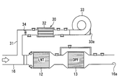
図1に示す燃焼システムは、エンジン10、LNT12、DPF13を備えている。燃焼システムは車両に搭載されたものであり、この車両は、エンジン10の出力を駆動源として走行する。エンジン10は、圧縮自着火式のディーゼルエンジンであり、燃焼に用いる燃料には、炭化水素化合物である軽油を用いている。エンジン10には、このエンジン10に空気を供給する吸気通路と、エンジン10からの排気を放出する排気通路16とが接続されている。排気通路16は、排気マニホールドを介してエンジン10の排気側に接続されている。なお、エンジン10が内燃機関に相当する。
図1に示す燃焼システムは、エンジン10、LNT12、DPF13を備えている。燃焼システムは車両に搭載されたものであり、この車両は、エンジン10の出力を駆動源として走行する。エンジン10は、圧縮自着火式のディーゼルエンジンであり、燃焼に用いる燃料には、炭化水素化合物である軽油を用いている。エンジン10には、このエンジン10に空気を供給する吸気通路と、エンジン10からの排気を放出する排気通路16とが接続されている。排気通路16は、排気マニホールドを介してエンジン10の排気側に接続されている。なお、エンジン10が内燃機関に相当する。
LNT12(Lean NOx Traps)は、NOx吸蔵還元型触媒であり、排気通路16に設けられている。DPF13(Diesel Particulate Filter)は、排気に含まれた微粒子を捕集する微粒子捕集装置であり、LNT12の下流側に配置されている。排気通路16を流れる排気は、LNT12及びDPF13の両方を通過した後に、排気出口16aから放出される。なお、LNT12及びDPF13が排気浄化装置を構成している。
燃焼システムは、排気通路16においてLNT12の上流側にオゾンO3を供給するオゾン供給装置30を有している。オゾン供給装置30から排気通路16にオゾンが供給された場合、オゾンにより排気中のNOがNO2に酸化されることでNO2の割合が増加し、その結果、LNT12でのNOx吸蔵率が向上する。オゾン供給装置30は、排気通路16にオゾンを供給する供給状態と、オゾンを供給しない停止状態とに移行可能になっている。
また、燃焼システムは、図示しない過給機を有している。過給機は、排気タービン、回転軸及びコンプレッサを備える。排気タービンは、エンジンの排気通路16に配置され、排気の運動エネルギにより回転する。回転軸は、排気タービン及びコンプレッサの各インペラを結合することで、排気タービンの回転力をコンプレッサに伝達する。コンプレッサは、吸気通路に配置されており、吸気を圧縮してエンジン10に過給する。
オゾン供給装置30は、排気通路16に接続されたオゾン通路31と、オゾンを生成するオゾン生成器32と、オゾン通路31を通じてオゾン生成器32に空気を送るエアポンプ33と、オゾン通路31における排気の逆流を遮断する排気遮断弁34と、オゾン通路31の内部圧力を通路圧力として検出する圧力センサ35と、エアポンプ33からオゾン通路31に送られる空気の流量を通路流量として検出する流量センサ36とを有している。なお、オゾン通路31が導入通路に相当する。
オゾン通路31においては、その上流端にエアポンプ33が設けられており、エアポンプ33と排気通路16との間にオゾン生成器32が設けられている。エアポンプ33は、遠心式のエアポンプであり、電動モータにより駆動されるインペラをケース内に収容して構成される。エアポンプ33は、大気を吸入する吸入口33aを有しており、この吸入口33aはケースに形成されている。エアポンプ33は、送風状態に移行する送風部であり、送風量を変化させることが可能になっている。なお、エアポンプ33の吸入口33aがオゾン通路31の上流端を形成している。
オゾン生成器32は、その内部に流通路を形成するハウジングを備え、流通路には複数の電極が配置されている。これらの電極は、互いに平行に対向するように配置された平板形状であり、高電圧が印加される電極と接地電圧の電極とが交互に配置されている。オゾン生成器32のハウジングには、エアポンプ33により送風された空気が流入する。この空気は、ハウジング内の流通路に流入し、電極間の通路である電極間通路を流通する。
オゾン生成器32の電極へ通電すると、電極から放出された電子が、電極間通路の空気中に含まれる酸素分子に衝突する。すると、酸素分子からオゾンが生成される。つまり、オゾン生成器32は、放電により酸素分子をプラズマ状態にしてオゾンを生成する。したがって、オゾン生成器32への通電時には、オゾン生成器32から排気通路16に向けて流れる空気にオゾンが含まれる。なお、オゾン生成器32はオゾン生成部やオゾナイザと称することもできる。
排気遮断弁34は、機械式や電磁駆動式の開閉弁であり、オゾン通路31においてオゾン生成器32と排気通路16との間に設けられている。排気遮断弁34は、通気を可能にする開状態と、通気を遮断する閉状態とに移行可能になっており、閉状態が遮断状態に相当する。排気遮断弁34が開状態にある場合、オゾン通路31の通路流量は排気遮断弁34の開度に応じて調整される。オゾン通路31の通路流量は、排気遮断弁34が全開状態にある場合に最大になる。なお、排気遮断弁34が排気遮断部に相当する。
圧力センサ35は、オゾン通路31においてオゾン生成器32と排気遮断弁34との間に設けられている。具体的には、圧力センサ35は、オゾン生成器32寄りの位置に配置されている。この場合、圧力センサ35の検出結果に、排気遮断弁34の開閉に伴う圧力変化が反映されやすくなっている。なお、圧力センサ35が圧力検出部に相当する。
流量センサ36は、エアポンプ33とオゾン生成器32との間に設けられており、エアポンプ33からの空気の吐出量を検出可能になっている。具体的には、流量センサ36は、エアポンプ33寄りの位置に配置されている。この場合、流量センサ36の検出結果に、エアポンプ33の駆動及び停止に伴う空気の流量変化が反映されやすくなっている。なお、流量センサ36が流量検出部に相当する。
排気通路16において、オゾン通路31とLNT12との間にはミキサー37が設けられている。ミキサー37は、オゾン通路31から供給されたオゾンと排気とを混合させる混合部であり、ミキサー37の下流側においては、オゾンによる排気中のNOxの酸化が促進される。
燃焼システムの電気的な構成について説明する。燃焼システムはECU40を有しており、ECU40は、マイクロコンピュータ等のマイコン41を制御装置として有している。マイコン41は、各種フラグがセットされるメモリと、プログラムを記憶する記憶装置と、記憶されたプログラムに従って演算処理を実行する中央演算処理装置とを有している。マイコン41は、エンジン10の運転状態を制御するエンジン制御部41aと、オゾン供給装置30によるオゾン供給を制御するオゾン制御部41bとを有している。
エンジン制御部41aは、アクセル開度やエンジン負荷、エンジン回転速度等に基づき、燃料噴射弁の噴射量や噴射圧力、過給機の過給圧力、エンジン10への吸気量の制御を行う。ここで、ECU40にはアクセル開度センサ45が接続されている。アクセル開度センサ45は、運転者により操作されるアクセルペダルに設けられており、アクセルペダルの操作量をアクセル開度として検出可能になっている。この場合、アクセル開度は、アクセルペダルの操作量に基づいて取得される操作パラメータの1つであり、エンジン制御部41aは、操作パラメータに基づいてエンジン10の出力制御を行う。
ECU40には、圧力センサ35、流量センサ36、排気温度センサ51、差圧センサ52、NOxセンサ53、PMセンサ54、A/Fセンサ55、空気温度センサ56、空気湿度センサ57が接続されている。センサ51~55は排気通路16に設けられており、センサ56,57はオゾン通路31に設けられている。排気温度センサ51は、LNT12の上流側及び下流側のそれぞれに配置され、A/Fセンサ55は、LNT12の上流側に配置されている。差圧センサ52は、DPF13に対して設けられ、排気通路16においてDPF13の上流側と下流側との圧力差を検出する。空気温度センサ56は、オゾン生成器32の上流側及び下流側のそれぞれに配置され、空気湿度センサ57は、オゾン生成器32の上流側に配置されている。なお、図1において、センサ51~57とECU40との電気的な接続線の図示を省略している。
ECU40には、オゾン供給装置30のオゾン生成器32、エアポンプ33及び排気遮断弁34がアクチュエータとして接続されている。オゾン制御部41bは、エンジン回転速度やエンジン負荷等のエンジン10の作動状態の検出値に加え、センサ35,36,51~57により検出された物理量を取得する。そして、これらの物理量に基づき、オゾン供給装置30のアクチュエータの動作制御を行う。オゾン制御部41bは、例えば排気中に含まれるNOxやPMの量に応じて、オゾン生成器32のオゾン生成量や、エアポンプ33の送風量を可変設定する。
ここで、オゾン供給装置30において、排気遮断弁34が開状態のまま保持されてしまう開故障が発生した場合、排気が排気通路16からオゾン通路31に逆流し、エアポンプ33の吸入口33aから外部に放出されることが懸念される。これに対して、本実施形態では、排気遮断弁34の開故障が発生した場合、エンジン10の出力が制限されることで、オゾン通路31における排気の逆流がエアポンプ33の送風により規制されるようになっている。なお、開故障のうち、特に排気遮断弁34が全開状態から閉じなくなった故障を全開故障と称する。
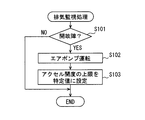
エンジン制御部41aは、排気通路16での排気の流れを監視する排気監視処理を実行する。ここでは、排気管理処理について、図2のフローチャートを参照しつつ説明する。なお、エンジン制御部41aは、排気管理処理を所定周期で繰り返し実行する。
図2において、S101では、排気遮断弁34の開故障が発生しているか否かを判定する。例えば、エアポンプ33の送風が停止した状況においては、排気遮断弁34の開故障が発生している場合、排気遮断弁34が適正に閉状態に移行した場合に比べて、圧力センサ35による検出圧力が及び流量センサ36による検出流量が小さくなる。このため、圧力センサ35及び流量センサ36の各検出結果に基づいて、排気遮断弁34の開故障の有無を判定可能になる。なお、S101が異常判定部に対応する。
なお、オゾン供給装置30を供給状態から停止状態に移行させる場合、オゾン制御部41bは、最初にオゾン生成器32を停止させる一方で、エアポンプ33の運転をある程度の期間だけ継続させることで、オゾン通路31からオゾンを排出する。そして、オゾン通路31からのオゾンの排出が終了した後に、排気遮断弁34を開状態から閉状態に移行させ、排気遮断弁34が閉状態に移行してからある程度の期間だけ経過した後に、エアポンプ33の運転を停止させる。ここで、オゾン供給装置30を停止させる場合、S101では、排気遮断弁34及びエアポンプ33の状態が移行することを利用して、検出電圧や検出流量の変化を監視して排気遮断弁34の開故障の発生の有無を判定している。
排気遮断弁34の開故障が発生している場合、S102に進み、エアポンプ33を運転状態に移行させる。エアポンプ33が運転状態にある場合には、そのまま運転状態を保持する。エアポンプ33の運転を開始する場合及び運転を継続させる場合のいずれについても、エアポンプ33をその送風量が最大になるように運転を行う。
S103では、運転者によるアクセルペダルの操作量に関係なく、アクセル開度の上限をあらかじめ定められた特定値に設定する。特定値は、排気通路16の排気量や排気圧力がエアポンプ33によるオゾン通路31の空気量や空気圧力より十分に小さくなる値に設定されており、ECU40の記憶装置に記憶されている。特定値は、試験やシミュレーションにより取得された値であり、例えばアクセル開度の最大値の25%の値に設定されている。
アクセル開度の上限を特定値に設定した後、次回以降に実行した排気監視処理のS103では、排気遮断弁34の開度やオゾン通路31の通路流量、排気通路16の排気流量等に関係なく、アクセル開度の上限を特定値に保持する。この場合、運転者は、アクセルペダルの操作量がある程度の大きさに達した後には、その操作量を更に大きくしてもエンジン出力が上がらず車両速度も大きくならないことを知ることになる。これにより、排気遮断弁34の開故障という異常の種類までは分からなくても、何らかの異常が発生していることを運転者に察知させることができる。
なお、S103は、エンジン10の出力制限を開始させるべくアクセル開度の上限を初期値としての特定値に設定する開始機能と、その後にアクセル開度の上限を特定値に保持する保持機能とを有している。この場合、S103の開始機能が開始設定部に相当し、保持機能が上限保持部に相当する。また、S103は、出力制限部、特定設定部に対応する。
また、排気遮断弁34の開故障が発生している場合、その旨を記憶する処理や報知する処理を行う。報知処理としては、インストルメントパネルの表示装置等に表示する処理が挙げられる。
図3に示すように、排気遮断弁34が適正に閉状態に移行した場合、排気通路16の排気量や排気圧力に関係なく、排気がオゾン通路31を逆流するということが排気遮断弁34により阻止される。これに対して、排気遮断弁34の開故障として全開故障が発生していても、アクセル開度の上限が特定値に設定されることで、図4に示すように、排気通路16の排気量や排気圧力がエアポンプ33による送風量や送風圧力より小さくなる。これにより、オゾン通路31における排気の逆流が規制される。
なお、排気遮断弁34の開故障が修理等により解消された場合、エンジン制御部41aに所定のリセット信号等が入力されることで、アクセル開度の上限を特定値とする設定が解除される。これにより、開故障が解消された後には、エンジン10の出力が制限されずに、アクセルペダルの操作量に応じてエンジン10の運転が行われることになる。
第1実施形態の作用効果を以下に説明する。
第1実施形態によれば、排気遮断弁34の開故障が発生した場合に、エンジン10の出力が制限されるため、排気がオゾン通路31を逆流するということを規制できる。この場合、エンジン10の運転を停止させなくても、オゾン通路31からの排気の放出を防止することが可能であるため、エンジン10の運転を低出力で継続させることで、運転者等は開故障に対する応急処置を適正に行うことができる。具体的には、車両を高速で走行させることはできなくても、運転者をその車両を自走させて修理工場やディーラーに持ち込むことができる。
また、エンジン10の出力が制限されることで、オゾン通路31における排気の逆流を規制するため、排気量や排気圧力を上回る送風量や送風圧力を有する送風機をエアポンプ33として選択する必要がない。送風能力の高い送風機をエアポンプ33として選択した場合、圧力損失の増加や、エアポンプ33及びモータの大型化、電力消費量の増加などが懸念される。これに対して、エンジン10の出力が制限されることで、これら懸念を解消できる。
第1実施形態によれば、排気遮断弁34の開故障が発生した場合、アクセル開度の上限がアクセルペダルの操作量に関係なく特定値に設定されるため、エンジン10の出力制限を行われる際のエンジン制御部41aの処理負担を低減できる。しかも、アクセル開度の上限が十分に小さい値に設定されることで、オゾン通路31において排気の逆流が生じることを確実に抑止できる。
第1実施形態によれば、排気遮断弁34の開故障が発生した場合に、アクセル開度の上限が特定値にて保持される。このため、アクセルペダルの操作量に対する車両速度変化の対応が遅いことに起因して、車両で何らかの異常が発生していることを運転者に察知させることができる。この場合、エンジン10の出力が制限されたとしても、運転者は、車両速度が低下することをある程度予測した上で運転操作を行うことが可能になるため、車両の走行安全性が極端に低下するということを回避できる。
第1実施形態によれば、オゾン通路31における排気の逆流が規制されるため、コンポーネントとしてのオゾン生成器32やエアポンプ33、圧力センサ35、流量センサ36などが排気で汚染されることを回避できる。この場合、排気遮断弁34の開故障が発生した場合に、他の部品や部材も修理対象や取り換え対象となることが回避されるため、車両の修理に対する手間やコストを低減できる。
第1実施形態によれば、排気遮断弁34そのものに異常が発生していなくても、例えばオゾン通路31の変形等に起因して排気遮断弁34の周囲等にて空気漏れが発生している場合でも、オゾン通路31における排気の逆流を規制できる。なお、排気遮断弁34の開故障と、排気遮断弁34の開故障が発生していなくても排気遮断弁34にて空気漏れが発生している異常とが、遮断異常に相当する。
(第2実施形態)
上記第1実施形態では、排気遮断弁34の開故障が発生した場合に、排気遮断弁34の開度に関係なくアクセル開度の上限が設定されたが、第2実施形態では、排気遮断弁34の開度に応じてアクセル開度の上限が設定される。ここでは、本実施形態の排気監視処理について図5のフローチャートを参照しつつ説明する。
上記第1実施形態では、排気遮断弁34の開故障が発生した場合に、排気遮断弁34の開度に関係なくアクセル開度の上限が設定されたが、第2実施形態では、排気遮断弁34の開度に応じてアクセル開度の上限が設定される。ここでは、本実施形態の排気監視処理について図5のフローチャートを参照しつつ説明する。
図5において、S201では、上記第1実施形態のS101と同じ処理を行う。なお、S201が異常判定部に対応する。
S202では、アクセル開度の上限が制限されていることを示す制限フラグについて、セットされているか否かを判定する。制限フラグがセットされていない場合、S203に進み、上記第1実施形態のS102と同様に、エアポンプ33を運転状態にする。
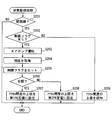
S204では、排気遮断弁34の開度を取得する。ここでは、排気遮断弁34の開度とオゾン通路31の通路圧力及び通路流量との関係を、エンジン10の出力レベルやエアポンプ33の運転の有無ごとに示すマップ等が記憶装置に記憶されている。そして、マップ等を用いて圧力センサ35及び流量センサ36の各検出結果に基づいて排気遮断弁34の開度を取得する。S205では、エンジン10の出力制限を開始するとして、制限フラグを記憶装置にセットする。
S206では、排気遮断弁34の故障が全開故障であるか否かを判定する。すなわち、排気遮断弁34が全開状態及び半開状態のいずれであるかを判定する。
開度が全開である場合、S207に進み、エンジン10の出力制限を開始するべく、アクセル開度の上限をあらかじめ定められた第1特定値に設定する。第1特定値は、例えば、上記第1実施形態の特定値と同様にアクセル開度の最大値の25%の値に設定されている。排気遮断弁34の開度が全開でない場合、S208に進み、S207と同様にエンジン10の出力制限を開始するべく、アクセル開度の上限を第1特定値より大きい第2特定値に設定する。なお、S207,S208が出力制限部、開始設定部及び特定設定部に対応する。
S202にて制限フラグがセットされていた場合、S209に進み、アクセル開度の上限を現状のまま保持する。アクセル開度の上限が第1特定値に設定されていた場合には、アクセル開度の上限を第1特定値にて保持し、第2特定値に設定されていた場合には、第2特定値にて保持する。なお、S209が出力制限部及び上限保持部に相当する。
第2実施形態によれば、排気遮断弁34の開故障が発生している場合に、その排気遮断弁34の開度に応じてエンジン10の出力レベルの上限が選択的に設定される。このため、オゾン通路31における排気の逆流規制を優先した上で、排気遮断弁34が全開でない場合には、エンジン10の出力レベルを極力上げることができる。これにより、エンジン10の出力レベルを制限することに伴うドライバビリティの低下を極力和らげることができる。
なお、排気遮断弁34が半開故障である場合のアクセル開度の上限が、排気遮断弁34が全開故障である場合のアクセル開度の上限より小さいため、排気遮断弁34の開度が小さいほどエンジン10の出力を大きくすることができる。これは、排気遮断弁34の開度が小さいほど、エアポンプ33の送風に伴うオゾン通路31の内部圧力が大きくなり、オゾン通路31における排気の逆流が生じにくくなるためである。
(第3実施形態)
上記第1実施形態では、排気遮断弁34の開故障が発生した場合に、オゾン通路31の通路流量に関係なくアクセル開度の上限が設定されたが、第3実施形態では、オゾン通路31の通路流量に応じてアクセル開度の上限が可変設定される。ここでは、本実施形態の排気監視処理について図6のフローチャートを参照しつつ説明する。
上記第1実施形態では、排気遮断弁34の開故障が発生した場合に、オゾン通路31の通路流量に関係なくアクセル開度の上限が設定されたが、第3実施形態では、オゾン通路31の通路流量に応じてアクセル開度の上限が可変設定される。ここでは、本実施形態の排気監視処理について図6のフローチャートを参照しつつ説明する。
図6において、S301では、上記第1実施形態のS101と同様の処理を行う。なお、S301が異常判定部に対応する。S302では、アクセル開度の上限が制限されていることを示す制限フラグについて、セットされているか否かを判定する。制限フラグがセットされていない場合、S303に進み、上記第1実施形態のS102と同様に、エアポンプ33を運転状態にする。
S304では、S301にて排気遮断弁34の開故障が肯定されてから、あらかじめ定められた所定時間(例えば数秒)が経過したか否かを判定する。ここで、排気遮断弁34の開故障が発生したタイミングや、エアポンプ33の運転が開始されたタイミングからある程度の時間を経過させることで、オゾン通路31での空気の流れが安定しやすくなると考えられる。なお、所定時間は、オゾン通路31での空気の流れが安定化するまでに要する時間であり、試験やシミュレーション等により取得され、記憶装置に記憶されている。
S305では、流量センサ36の検出結果に基づいてオゾン通路31の通路流量を取得する。ここで、S304の処理により、エアポンプ33の運転開始からある程度の経過時間が確保されているため、排気遮断弁34の開故障やエアポンプ33の運転開始等による通路流量の過渡期が過ぎた後に通路流量が取得されるようになっている。この結果、通路流量の取得精度が高められている。なお、流量センサ36は空気の流れる方向も検出可能になっており、ここでは、通路流量に加えて流れ方向も取得する。また、S305が流量取得部に対応する。
S306では、通路流量があらかじめ定められた判定値より小さいか否かを判定する。この判定処理は、判定値は、「0」より大きい値であり、エンジン10の出力レベルやエアポンプ33の送風量に多少の増減が生じても、オゾン通路31において排気の逆流が生じない程度の値になっている。なお、通路流量が「0」より小さい状態は、排気の逆流が生じていることになる。
通路流量が判定値より小さくない場合、アクセル開度の上限を制限しなくてもオゾン通路31での排気の逆流が生じにくいとして、そのまま本排気監視処理を終了する。
通路流量が判定値より小さい場合、S307にて制限フラグを記憶装置にセットし、S308にてアクセル開度の制限を行う。S308では、通路流量を判定値より小さくするために、アクセル開度の上限を設定する。ここで、アクセル開度の上限を設定することが、エンジン10の出力レベルを制限することになるとすれば、排気遮断弁34の開故障が発生しただけでなく、通路流量が判定値より小さくなった場合にはじめてエンジン10の出力レベル制限を開始することになる。S308が出力制限部、開始設定部及び流量対応設定部に対応する。
S302にて制限フラグがセットされていた場合、S309に進み、S305と同様にオゾン通路31の通路流量を取得する。S310では、S309にて取得された都度の通路流量に基づいて、アクセル開度の上限を可変設定する。この場合、通路流量が判定値より小さくならない範囲でのアクセル開度の最大値を算出し、この算出値をアクセル開度の上限として設定する。この場合、アクセル開度の上限を極力大きくすることで、エンジン10の出力レベルの上限が極力大きくなるため、運転者は車両速度を極力大きくした状態で車両を運転することができる。なお、制限フラグは、排気遮断弁34の開故障が解消された場合にクリアされる。S310が出力制限部に対応する。
第3実施形態によれば、排気遮断弁34の開故障が発生した場合でも、オゾン通路31の通路流量が判定値より小さくならなければ、アクセル開度の制限が行われないため、エンジン10の出力制限が行われる頻度を極力少なくできる。これにより、例えばオゾン通路31での排気の逆流が生じないほどに低速で車両が走行しているにもかかわらず更に車両速度が強制的に小さくなるという事態を抑制できる。
第3実施形態によれば、エンジン10の出力制限を開始する場合に、アクセル開度の上限がオゾン通路31の通路流量に基づいて設定されるため、エンジン10の出力が過剰に低下するということを回避できる。ここで、オゾン通路31の通路流量は、排気通路16の排気圧力とオゾン通路31の通路圧力との関係によって決まり、オゾン通路31の通路圧力は、排気遮断弁34の開度とエアポンプ33の送風量によって決まる。このため、アクセル開度の上限をオゾン通路31の通路流量に基づいて設定することは、開故障した排気遮断弁34の開度に加えて、経年劣化等によりエアポンプ33の送風能力が増減している可能性を考慮していることになる。したがって、排気遮断弁34の開故障が発生しても、オゾン通路31において排気の逆流が生じない範囲で、極力大きなエンジン出力が確保される。この場合、例えば高速道路を高速走行している車両について、排気遮断弁34の開故障が発生しても、エンジン10の出力の下げ幅が極力小さくなるため、車両の走行安全性が極端に低下するということを回避できる。
第3実施形態によれば、アクセル開度の上限がオゾン通路31の通路流量に応じて可変設定されるため、オゾン通路31での排気の逆流防止を優先した上で、エンジン10の出力レベルを極力高くすることができる。これにより、ユーザは、走行安全性が過剰に低下しない程度の速度で車両を走行させることができる。
(第4実施形態)
上記第1実施形態では、排気遮断弁34の開故障が発生した場合に、車両速度に関係なくアクセル開度の上限が設定されたが、第4実施形態では、車両速度に応じてアクセル開度の上限が可変設定される。ここでは、本実施形態の排気監視処理について図7のフローチャートを参照しつつ説明する。
上記第1実施形態では、排気遮断弁34の開故障が発生した場合に、車両速度に関係なくアクセル開度の上限が設定されたが、第4実施形態では、車両速度に応じてアクセル開度の上限が可変設定される。ここでは、本実施形態の排気監視処理について図7のフローチャートを参照しつつ説明する。
図7において、S401,S402では、上記第1実施形態のS101,S102と同じ処理を行う。S401が異常判定部に対応する。
S403では、S304と同様に、S401にて排気遮断弁34の開故障が肯定されてから、あらかじめ定められた所定時間(例えば数秒)が経過したか否かを判定する。
S404では、車両速度を取得し、S405では、車両速度があらかじめ定められた判定速度より小さいか否かを判定する。判定速度は、例えば80km/hとされる。この場合、車両が高速走行をしているか否かを判定することになる。
車両速度が判定速度より小さい場合、すなわち、車両が高速走行をしていない場合、S406に進み、上記第1実施形態のS103と同様に、アクセル開度の上限を特定値に設定する。一方、車両速度が判定速度より小さくない場合、すなわち、車両が高速走行をしている場合、S407に進み、上記第3実施形態のS308と同様に、アクセル開度の上限を通路流量に応じて設定する。
S406,S407は、上記第1実施形態のS103と同様に、エンジン10の出力制限を開始させる開始機能と、制限態様を保持する保持機能とを有している。この場合、S406,S407の開始機能が開始設定部に相当し、保持機能が上限保持部に相当する。また、S406,S407が出力制限部、特定設定部及び車速対応設定部に対応する。特に、S407が流量対応設定部に対応する。
第4実施形態によれば、車両が一般道などを低速で走行している場合には、アクセル開度の上限が特定値に設定される。このため、エンジン10の出力制限がある程度大きくても走行安全性が過剰に低下しないとして、オゾン通路31における排気の逆流防止を優先することができる。その一方で、車両が高速道路などを高速で走行している場合には、アクセル開度の上限が可変設定される。このため、オゾン通路31における排気の逆流防止を行いつつ、走行安全性を極力高めることができる。
(他の実施形態)
複数の実施形態について説明したが、本開示は、それらの実施形態に限定して解釈されるものではなく、本開示の要旨を逸脱しない範囲内において種々の実施形態及び組み合わせに適用することができる。
複数の実施形態について説明したが、本開示は、それらの実施形態に限定して解釈されるものではなく、本開示の要旨を逸脱しない範囲内において種々の実施形態及び組み合わせに適用することができる。
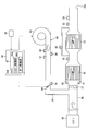
変形例1では、排気通路16には空気と共にオゾンが導入されなくてもよい。例えば、図8に示すように、排気通路16に空気を供給する空気導入装置60が燃焼システムに含まれた構成とする。この構成において、空気導入装置60は、オゾン供給装置30と同様に、排気通路16に接続された導入通路61と、導入通路61を通じて排気通路16に空気を送るエアポンプ63と、導入通路61における排気の逆流を遮断する排気遮断弁64とを有している。この構成では、エアポンプ63が送風部に相当し、排気遮断弁64が排気遮断部に相当する。この構成でも、エンジン10の出力制限を行うことで、導入通路61における排気の逆流をエアポンプ63の送風によって規制できる。
変形例2では、エンジン10の出力制御に用いられる操作パラメータとしては、アクセル開度の他にも、燃料噴射弁に対して設定される目標噴射量や、スロットルバルブに対して設定される目標吸入空気量などが挙げられる。同様に、エンジン10の出力レベルを制限する方法としては、アクセル開度の上限を設定する方法の他にも、スロットルバルブによる吸入空気量、燃料噴射弁の噴射量、噴射圧力、過給圧力などの上限を設定する方法が挙げられる。
変形例3では、オゾン通路31の通路流量が流量センサ36の検出結果に基づいて取得されるのではなく、エアポンプ33の駆動電流値に基づいて取得されてもよい。
変形例4では、上記第3実施形態において、S306での判定値を「0」にしてもよい。この場合、仮にオゾン通路31における排気の逆流が発生し始めたとしても、エンジン10の出力制限が即座に行われることで、その排気がオゾン通路31の上流端部から外部に放出されることを規制できる。
変形例5では、上記第3実施形態において、排気遮断弁34の開故障が肯定された後に所定時間を経過することなく、S305にて通路流量が取得されてもよい。つまり、S304の処理が行われなくてもよい。また、通路流量が取得されるタイミングは、エアポンプ33の運転が開始されたタイミングを基準として、この開始タイミングよりも後であればよい。
変形例6では、上記第4実施形態において、排気遮断弁34の開故障が肯定された後に所定時間を経過することなく、S404にて車両速度が取得されてもよい。つまり、S403の処理が行われなくてもよい。
変形例7では、エアポンプ33がオゾン通路31の下流端部や中間位置に配置されていてもよい。ただし、エアポンプ33にPM等が付着することを回避する上で、エアポンプ33はオゾン通路31において排気遮断弁34の上流側に配置されることが好ましい。
変形例8では、排気遮断弁34の開故障を検出するセンサが設けられていてもよい。この場合、排気遮断弁34の開故障の検出精度を高めることができる。
変形例9では、上記第4実施形態において、S404の判定要件に車両の走行状況を含めてもよい。例えば、車両の位置情報に基づいて、車両が高速道路を走行しているか否かを判定し、高速道路を走行している場合に車両速度が判定速度より小さいか否かを判定する。これにより、エンジン10の出力制限による走行安全性の低下を極力抑制できる。
変形例10では、燃焼システムが有するエンジン10がディーゼルエンジンではなく、ガソリンエンジンでもよい。
変形例11では、エンジン10が車両に搭載された車載エンジンではなく、可搬型の発電用エンジンであってもよい。例えば、可搬型の発電用エンジンから照明器具等の電気設備に電力が供給される構成とする。この発電用エンジンには、出力を調整するための操作部が設けられていない。この構成では、排気遮断弁の遮断異常が発生した場合に、点灯させる照明器具の数を減らすなどして電気的な負荷を減少させることで、必要最低限の電気設備を継続して使用することが可能になる。この場合でも、ユーザは遮断異常の発生に対して応急処置を適正に行うことができる。
Claims (8)
- 内燃機関(10)からの排気が流れる排気通路(16)に接続され、前記排気通路に空気を導入する導入通路(31,61)と、
前記導入通路を通じて前記排気通路に空気を送る送風部(33,63)と、
前記導入通路における排気の逆流を遮断する排気遮断部(34,64)と、
を備えている燃焼システムに適用された制御装置(41)であって、
前記排気遮断部により排気の逆流が遮断されない遮断異常が発生しているか否かを判定する異常判定部(S101,S201,S301,S401)と、
前記異常判定部により前記遮断異常の発生が肯定された場合に、前記送風部の送風により前記導入通路における排気の逆流を規制するべく、前記内燃機関の出力を制限する出力制限部(S103,S207,S208,S209,S308,S310,S406,S407)と、
を備えている燃焼システムの制御装置。 - 前記制御装置は、ユーザの操作量から取得した操作パラメータに基づいて前記内燃機関の出力制御を行うものであり、
前記出力制限部は、
前記内燃機関の出力制限を開始するべく、前記ユーザの操作量に関係なく前記操作パラメータの上限を設定する開始設定部(S103,S207,S208,S308,S406,S407)を有している請求項1に記載の燃焼システムの制御装置。 - 前記開始設定部は、
前記送風部の送風による前記導入通路での流量に関係なく、前記操作パラメータの上限をあらかじめ定められた特定値に設定する特定設定部(S103,S207,S208,S406,S407)を有している請求項2に記載の燃焼システムの制御装置。 - 前記開始設定部は、
前記異常判定部により前記遮断異常の発生が肯定された後の前記送風部の送風による前記導入通路での流量に基づいて、前記操作パラメータの上限を設定する流量対応設定部(S308,S407)を有している請求項2又は3に記載の燃焼システムの制御装置。 - 前記燃焼システムは車両に搭載されており、
前記開始設定部は、
前記異常判定部により前記遮断異常の発生が肯定された後の前記車両の走行速度に基づいて前記操作パラメータの上限を設定する車速対応設定部(S406,S407)を有している請求項2~4のいずれか1つに記載の燃焼システムの制御装置。 - 前記出力制限部は、
前記開始設定部により設定された前記操作パラメータの上限を、前記送風部の送風による前記導入通路での流量に関係なく保持する上限保持部(S103,S209,S406,S407)を有している請求項2~5のいずれか1つに記載の燃焼システムの制御装置。 - 前記送風部の送風による前記導入通路での流量を通路流量として流量取得部(S305)を備え、
前記出力制限部は、
前記異常判定部により前記遮断異常の発生が肯定され、且つ前記流量取得部により取得された前記通路流量があらかじめ定められた判定値より小さくなった場合に、前記内燃機関の出力制限を開始する制限開始部(S308)を有している請求項1~6のいずれか1つに記載の燃焼システムの制御装置。 - 前記燃焼システムは、
前記導入通路に設けられ、オゾンを生成するオゾン生成部(32)を有しており、
前記送風部は、前記オゾン生成部により生成されたオゾンを送風で前記排気通路に供給するものであり、
前記排気遮断部は、前記導入通路において前記オゾン生成部より下流側に設けられている請求項1~7のいずれか1つに記載の燃焼システムの制御装置。
Priority Applications (1)
| Application Number | Priority Date | Filing Date | Title |
|---|---|---|---|
| DE112016004539.5T DE112016004539T5 (de) | 2015-10-05 | 2016-09-05 | Steuervorrichtung für ein Verbrennungssystem |
Applications Claiming Priority (2)
| Application Number | Priority Date | Filing Date | Title |
|---|---|---|---|
| JP2015-197773 | 2015-10-05 | ||
| JP2015197773A JP6409731B2 (ja) | 2015-10-05 | 2015-10-05 | 燃焼システムの制御装置 |
Publications (1)
| Publication Number | Publication Date |
|---|---|
| WO2017061201A1 true WO2017061201A1 (ja) | 2017-04-13 |
Family
ID=58487481
Family Applications (1)
| Application Number | Title | Priority Date | Filing Date |
|---|---|---|---|
| PCT/JP2016/075931 Ceased WO2017061201A1 (ja) | 2015-10-05 | 2016-09-05 | 燃焼システムの制御装置 |
Country Status (3)
| Country | Link |
|---|---|
| JP (1) | JP6409731B2 (ja) |
| DE (1) | DE112016004539T5 (ja) |
| WO (1) | WO2017061201A1 (ja) |
Cited By (1)
| Publication number | Priority date | Publication date | Assignee | Title |
|---|---|---|---|---|
| CN112943428A (zh) * | 2021-02-05 | 2021-06-11 | 广西玉柴机器股份有限公司 | 一种准确度高的发动机后处理hc喷射系统诊断方法 |
Families Citing this family (1)
| Publication number | Priority date | Publication date | Assignee | Title |
|---|---|---|---|---|
| WO2020083100A1 (zh) * | 2018-10-22 | 2020-04-30 | 上海必修福企业管理有限公司 | 一种发动机排放处理系统和方法 |
Citations (2)
| Publication number | Priority date | Publication date | Assignee | Title |
|---|---|---|---|---|
| JP2006063945A (ja) * | 2004-08-30 | 2006-03-09 | Toyota Motor Corp | 内燃機関の制御装置 |
| JP2011185118A (ja) * | 2010-03-05 | 2011-09-22 | Toyota Motor Corp | 内燃機関の排気浄化装置 |
Family Cites Families (1)
| Publication number | Priority date | Publication date | Assignee | Title |
|---|---|---|---|---|
| JP6351337B2 (ja) | 2014-04-01 | 2018-07-04 | 日本無線株式会社 | 航行情報判別装置 |
-
2015
- 2015-10-05 JP JP2015197773A patent/JP6409731B2/ja not_active Expired - Fee Related
-
2016
- 2016-09-05 WO PCT/JP2016/075931 patent/WO2017061201A1/ja not_active Ceased
- 2016-09-05 DE DE112016004539.5T patent/DE112016004539T5/de not_active Withdrawn
Patent Citations (2)
| Publication number | Priority date | Publication date | Assignee | Title |
|---|---|---|---|---|
| JP2006063945A (ja) * | 2004-08-30 | 2006-03-09 | Toyota Motor Corp | 内燃機関の制御装置 |
| JP2011185118A (ja) * | 2010-03-05 | 2011-09-22 | Toyota Motor Corp | 内燃機関の排気浄化装置 |
Cited By (2)
| Publication number | Priority date | Publication date | Assignee | Title |
|---|---|---|---|---|
| CN112943428A (zh) * | 2021-02-05 | 2021-06-11 | 广西玉柴机器股份有限公司 | 一种准确度高的发动机后处理hc喷射系统诊断方法 |
| CN112943428B (zh) * | 2021-02-05 | 2022-04-19 | 广西玉柴机器股份有限公司 | 一种准确度高的发动机后处理hc喷射系统诊断方法 |
Also Published As
| Publication number | Publication date |
|---|---|
| JP6409731B2 (ja) | 2018-10-24 |
| DE112016004539T5 (de) | 2018-06-14 |
| JP2017072029A (ja) | 2017-04-13 |
Similar Documents
| Publication | Publication Date | Title |
|---|---|---|
| US8844343B2 (en) | Apparatus for diagnosing exhaust gas recirculation and method thereof | |
| JP2009264207A (ja) | エバポガスパージシステムのフロー診断装置 | |
| JP6354734B2 (ja) | 内燃機関の異常検出装置 | |
| JP6409731B2 (ja) | 燃焼システムの制御装置 | |
| CN109768304A (zh) | 燃料电池系统以及控制燃料电池系统的方法 | |
| JP6384429B2 (ja) | オゾン供給装置の故障診断システム | |
| JP6620856B2 (ja) | 燃焼システムの制御装置 | |
| JP6413998B2 (ja) | オゾン供給装置の制御システム | |
| JP4365342B2 (ja) | ターボチャージャの異常判定装置 | |
| JP5525549B2 (ja) | 自動車の自動停止を管理する方法 | |
| JPWO2014027394A1 (ja) | 内燃機関の添加剤供給装置 | |
| JP4661644B2 (ja) | 内燃機関のパージフロー診断装置 | |
| US9163587B2 (en) | Low-pressure loop EGR device | |
| WO2014045880A1 (ja) | 内燃機関 | |
| JP2632017B2 (ja) | 内燃エンジンにおける故障検知方法 | |
| EP1749998A1 (en) | Intake air charger diagnostic system | |
| JP2005147072A (ja) | 車両用電子制御装置 | |
| JP4650834B2 (ja) | 2次空気供給装置のリードバルブの異常検出装置 | |
| JP7697589B2 (ja) | 蒸発燃料処理装置の故障診断方法および装置 | |
| US20240295197A1 (en) | Removal determination device for exhaust gas control apparatus | |
| JP2008128090A (ja) | エンジンの過給装置 | |
| JP4534160B2 (ja) | 内燃機関の二次空気供給システムの異常診断装置 | |
| JP4561446B2 (ja) | 内燃機関の二次エア供給制御装置 | |
| JP5957919B2 (ja) | 内燃機関の過給補助装置の故障診断方法及び内燃機関の過給補助システム | |
| JPH08246851A (ja) | 内燃機関の2次空気供給装置 |
Legal Events
| Date | Code | Title | Description |
|---|---|---|---|
| 121 | Ep: the epo has been informed by wipo that ep was designated in this application |
Ref document number: 16853355 Country of ref document: EP Kind code of ref document: A1 |
|
| WWE | Wipo information: entry into national phase |
Ref document number: 112016004539 Country of ref document: DE |
|
| 122 | Ep: pct application non-entry in european phase |
Ref document number: 16853355 Country of ref document: EP Kind code of ref document: A1 |