WO2017061167A1 - Compresseur à plusieurs étages et système de réfrigération équipé de ce dernier - Google Patents
Compresseur à plusieurs étages et système de réfrigération équipé de ce dernier Download PDFInfo
- Publication number
- WO2017061167A1 WO2017061167A1 PCT/JP2016/072994 JP2016072994W WO2017061167A1 WO 2017061167 A1 WO2017061167 A1 WO 2017061167A1 JP 2016072994 W JP2016072994 W JP 2016072994W WO 2017061167 A1 WO2017061167 A1 WO 2017061167A1
- Authority
- WO
- WIPO (PCT)
- Prior art keywords
- refrigerant
- housing
- electric motor
- compression mechanism
- injection nozzle
- Prior art date
Links
Images


Classifications
-
- F—MECHANICAL ENGINEERING; LIGHTING; HEATING; WEAPONS; BLASTING
- F04—POSITIVE - DISPLACEMENT MACHINES FOR LIQUIDS; PUMPS FOR LIQUIDS OR ELASTIC FLUIDS
- F04C—ROTARY-PISTON, OR OSCILLATING-PISTON, POSITIVE-DISPLACEMENT MACHINES FOR LIQUIDS; ROTARY-PISTON, OR OSCILLATING-PISTON, POSITIVE-DISPLACEMENT PUMPS
- F04C23/00—Combinations of two or more pumps, each being of rotary-piston or oscillating-piston type, specially adapted for elastic fluids; Pumping installations specially adapted for elastic fluids; Multi-stage pumps specially adapted for elastic fluids
- F04C23/001—Combinations of two or more pumps, each being of rotary-piston or oscillating-piston type, specially adapted for elastic fluids; Pumping installations specially adapted for elastic fluids; Multi-stage pumps specially adapted for elastic fluids of similar working principle
-
- F—MECHANICAL ENGINEERING; LIGHTING; HEATING; WEAPONS; BLASTING
- F04—POSITIVE - DISPLACEMENT MACHINES FOR LIQUIDS; PUMPS FOR LIQUIDS OR ELASTIC FLUIDS
- F04B—POSITIVE-DISPLACEMENT MACHINES FOR LIQUIDS; PUMPS
- F04B39/00—Component parts, details, or accessories, of pumps or pumping systems specially adapted for elastic fluids, not otherwise provided for in, or of interest apart from, groups F04B25/00 - F04B37/00
- F04B39/06—Cooling; Heating; Prevention of freezing
-
- F—MECHANICAL ENGINEERING; LIGHTING; HEATING; WEAPONS; BLASTING
- F04—POSITIVE - DISPLACEMENT MACHINES FOR LIQUIDS; PUMPS FOR LIQUIDS OR ELASTIC FLUIDS
- F04C—ROTARY-PISTON, OR OSCILLATING-PISTON, POSITIVE-DISPLACEMENT MACHINES FOR LIQUIDS; ROTARY-PISTON, OR OSCILLATING-PISTON, POSITIVE-DISPLACEMENT PUMPS
- F04C23/00—Combinations of two or more pumps, each being of rotary-piston or oscillating-piston type, specially adapted for elastic fluids; Pumping installations specially adapted for elastic fluids; Multi-stage pumps specially adapted for elastic fluids
- F04C23/005—Combinations of two or more pumps, each being of rotary-piston or oscillating-piston type, specially adapted for elastic fluids; Pumping installations specially adapted for elastic fluids; Multi-stage pumps specially adapted for elastic fluids of dissimilar working principle
-
- F—MECHANICAL ENGINEERING; LIGHTING; HEATING; WEAPONS; BLASTING
- F04—POSITIVE - DISPLACEMENT MACHINES FOR LIQUIDS; PUMPS FOR LIQUIDS OR ELASTIC FLUIDS
- F04C—ROTARY-PISTON, OR OSCILLATING-PISTON, POSITIVE-DISPLACEMENT MACHINES FOR LIQUIDS; ROTARY-PISTON, OR OSCILLATING-PISTON, POSITIVE-DISPLACEMENT PUMPS
- F04C23/00—Combinations of two or more pumps, each being of rotary-piston or oscillating-piston type, specially adapted for elastic fluids; Pumping installations specially adapted for elastic fluids; Multi-stage pumps specially adapted for elastic fluids
- F04C23/008—Hermetic pumps
-
- F—MECHANICAL ENGINEERING; LIGHTING; HEATING; WEAPONS; BLASTING
- F04—POSITIVE - DISPLACEMENT MACHINES FOR LIQUIDS; PUMPS FOR LIQUIDS OR ELASTIC FLUIDS
- F04C—ROTARY-PISTON, OR OSCILLATING-PISTON, POSITIVE-DISPLACEMENT MACHINES FOR LIQUIDS; ROTARY-PISTON, OR OSCILLATING-PISTON, POSITIVE-DISPLACEMENT PUMPS
- F04C29/00—Component parts, details or accessories of pumps or pumping installations, not provided for in groups F04C18/00 - F04C28/00
- F04C29/04—Heating; Cooling; Heat insulation
- F04C29/042—Heating; Cooling; Heat insulation by injecting a fluid
-
- F—MECHANICAL ENGINEERING; LIGHTING; HEATING; WEAPONS; BLASTING
- F04—POSITIVE - DISPLACEMENT MACHINES FOR LIQUIDS; PUMPS FOR LIQUIDS OR ELASTIC FLUIDS
- F04C—ROTARY-PISTON, OR OSCILLATING-PISTON, POSITIVE-DISPLACEMENT MACHINES FOR LIQUIDS; ROTARY-PISTON, OR OSCILLATING-PISTON, POSITIVE-DISPLACEMENT PUMPS
- F04C29/00—Component parts, details or accessories of pumps or pumping installations, not provided for in groups F04C18/00 - F04C28/00
- F04C29/04—Heating; Cooling; Heat insulation
- F04C29/045—Heating; Cooling; Heat insulation of the electric motor in hermetic pumps
-
- F—MECHANICAL ENGINEERING; LIGHTING; HEATING; WEAPONS; BLASTING
- F25—REFRIGERATION OR COOLING; COMBINED HEATING AND REFRIGERATION SYSTEMS; HEAT PUMP SYSTEMS; MANUFACTURE OR STORAGE OF ICE; LIQUEFACTION SOLIDIFICATION OF GASES
- F25B—REFRIGERATION MACHINES, PLANTS OR SYSTEMS; COMBINED HEATING AND REFRIGERATION SYSTEMS; HEAT PUMP SYSTEMS
- F25B1/00—Compression machines, plants or systems with non-reversible cycle
- F25B1/10—Compression machines, plants or systems with non-reversible cycle with multi-stage compression
-
- F—MECHANICAL ENGINEERING; LIGHTING; HEATING; WEAPONS; BLASTING
- F04—POSITIVE - DISPLACEMENT MACHINES FOR LIQUIDS; PUMPS FOR LIQUIDS OR ELASTIC FLUIDS
- F04C—ROTARY-PISTON, OR OSCILLATING-PISTON, POSITIVE-DISPLACEMENT MACHINES FOR LIQUIDS; ROTARY-PISTON, OR OSCILLATING-PISTON, POSITIVE-DISPLACEMENT PUMPS
- F04C18/00—Rotary-piston pumps specially adapted for elastic fluids
- F04C18/02—Rotary-piston pumps specially adapted for elastic fluids of arcuate-engagement type, i.e. with circular translatory movement of co-operating members, each member having the same number of teeth or tooth-equivalents
- F04C18/0207—Rotary-piston pumps specially adapted for elastic fluids of arcuate-engagement type, i.e. with circular translatory movement of co-operating members, each member having the same number of teeth or tooth-equivalents both members having co-operating elements in spiral form
- F04C18/0215—Rotary-piston pumps specially adapted for elastic fluids of arcuate-engagement type, i.e. with circular translatory movement of co-operating members, each member having the same number of teeth or tooth-equivalents both members having co-operating elements in spiral form where only one member is moving
-
- F—MECHANICAL ENGINEERING; LIGHTING; HEATING; WEAPONS; BLASTING
- F04—POSITIVE - DISPLACEMENT MACHINES FOR LIQUIDS; PUMPS FOR LIQUIDS OR ELASTIC FLUIDS
- F04C—ROTARY-PISTON, OR OSCILLATING-PISTON, POSITIVE-DISPLACEMENT MACHINES FOR LIQUIDS; ROTARY-PISTON, OR OSCILLATING-PISTON, POSITIVE-DISPLACEMENT PUMPS
- F04C18/00—Rotary-piston pumps specially adapted for elastic fluids
- F04C18/30—Rotary-piston pumps specially adapted for elastic fluids having the characteristics covered by two or more of groups F04C18/02, F04C18/08, F04C18/22, F04C18/24, F04C18/48, or having the characteristics covered by one of these groups together with some other type of movement between co-operating members
- F04C18/34—Rotary-piston pumps specially adapted for elastic fluids having the characteristics covered by two or more of groups F04C18/02, F04C18/08, F04C18/22, F04C18/24, F04C18/48, or having the characteristics covered by one of these groups together with some other type of movement between co-operating members having the movement defined in group F04C18/08 or F04C18/22 and relative reciprocation between the co-operating members
- F04C18/356—Rotary-piston pumps specially adapted for elastic fluids having the characteristics covered by two or more of groups F04C18/02, F04C18/08, F04C18/22, F04C18/24, F04C18/48, or having the characteristics covered by one of these groups together with some other type of movement between co-operating members having the movement defined in group F04C18/08 or F04C18/22 and relative reciprocation between the co-operating members with vanes reciprocating with respect to the outer member
-
- F—MECHANICAL ENGINEERING; LIGHTING; HEATING; WEAPONS; BLASTING
- F04—POSITIVE - DISPLACEMENT MACHINES FOR LIQUIDS; PUMPS FOR LIQUIDS OR ELASTIC FLUIDS
- F04C—ROTARY-PISTON, OR OSCILLATING-PISTON, POSITIVE-DISPLACEMENT MACHINES FOR LIQUIDS; ROTARY-PISTON, OR OSCILLATING-PISTON, POSITIVE-DISPLACEMENT PUMPS
- F04C2270/00—Control; Monitoring or safety arrangements
- F04C2270/19—Temperature
- F04C2270/195—Controlled or regulated
Definitions
- the present invention relates to a multistage compressor and a refrigeration system provided with the same.
- a compressor for compressing gas refrigerant in an air conditioner or refrigeration apparatus As a compressor for compressing gas refrigerant in an air conditioner or refrigeration apparatus, a low-stage compression mechanism, a high-stage compression mechanism, and an electric motor for driving these compressors are provided in a housing formed in a closed container shape.
- a multi-stage compressor in which is housed.
- an electric motor is installed at an axial center in a substantially cylindrical housing, and the electric motor is driven by a main shaft driven by the electric motor.
- the lower stage side compression mechanism installed in the lower part of the above and the higher stage side compression mechanism installed in the upper part of the electric motor are coaxially driven.
- the multi-stage compressor described in Patent Document 1 includes an injection circuit which injects a gas refrigerant at an intermediate pressure extracted from the refrigerant circuit into the housing as an injection refrigerant.
- the injection circuit communicates with a first circuit connected in communication with the electric motor on the same side of the housing space on the same side as the high-stage side compression mechanism and a housing internal space on the opposite side of the high-stage side compression mechanism with the electric motor interposed. It comprises a second circuit connected and a switching mechanism for selectively communicating the first circuit and the second circuit into the housing according to the dryness of the injected refrigerant.
- the switching mechanism switches the injection circuit to the first circuit when the dryness of the injection refrigerant is equal to or higher than the set value, and the injection refrigerant having a high degree of thirst from the opening of the first circuit, that is, the dried refrigerant is contained inside the housing. Inject.
- the gas refrigerant of intermediate pressure is supplied to the high stage side compression mechanism, and the reduction of the suction efficiency of the high stage side compression mechanism is prevented to enhance the compression efficiency. be able to.
- the switching mechanism switches the injection circuit to the second circuit when the dryness of the injection refrigerant is less than the set value, and the injection circuit with low thirst from the opening of the second circuit, that is, the moist refrigerant is contained inside the housing Inject.
- the moist injection refrigerant passes through the vicinity of the electric motor, is heated by the operation heat of the electric motor, and the liquid is vaporized to be a dried gas refrigerant and sucked into the high-stage compression mechanism. This eliminates the possibility of liquid compression in the high-stage compression mechanism.
- the multi-stage compressor of Patent Document 1 detects the dryness of the injection refrigerant, and when the dryness is lower than a predetermined value, the injection refrigerant is allowed to pass through the electric motor so as to pass through the electric motor.
- the operation heat is used to dry the injection refrigerant, thereby preventing the liquid refrigerant from being sucked into the high-stage compression mechanism.
- the coil temperature rises under the operating condition where the circulating amount of the refrigerant decreases or the motor efficiency decreases, and the operation has to be stopped for safety when reaching the specified upper limit temperature.
- the injection refrigerant when the injection refrigerant is injected into the housing from the first circuit, the injection refrigerant does not pass through the electric motor, and thus the electric motor operates as described above at this timing. Overheating may limit the operable range.
- the present invention has been made in view of such circumstances, and after improving the system efficiency by injection, while preventing liquid compression in the high stage side compression mechanism, the injection refrigerant always keeps the electric motor effective. It is an object of the present invention to provide a multistage compressor which can be cooled to expand its operable range and a refrigeration system provided with the same.
- the multi-stage compressor according to the present invention comprises a housing in the form of a closed container, a low stage compression mechanism and a high stage compression mechanism installed in the housing, and an intermediate pressure area in the housing.
- a refrigerant supply unit for extracting a part and a liquid phase and selectively supplying the extracted part as an injection refrigerant to the injection nozzle;
- the refrigerant supply portion selectively supplies the gas phase component and the liquid phase component of the compressed refrigerant discharged from the high stage side compression mechanism to the injection nozzle, and the injection nozzle to the electric motor It is injected. That is, the gas refrigerant or the liquid refrigerant can be selectively injected to the electric motor. Alternatively, the gas refrigerant and the liquid refrigerant can be mixed and injected to the electric motor.
- the electric motor can be always cooled effectively by the injection refrigerant, and the operable range can be expanded.
- the refrigerant supply unit is a first refrigerant supply passage that is branched from a condensing refrigerant passage through which the compressed refrigerant discharged from the high stage side compression mechanism and condensed and cooled flows and is connected to the injection nozzle
- a second refrigerant supply passage extending from a liquid surface space of a gas-liquid separator for gas-liquid separation of the compressed refrigerant discharged from the high stage side compression mechanism and connected to the injection nozzle; and the first refrigerant supply passage
- the on-off valve may be opened when the operating temperature of the electric motor reaches a predetermined threshold temperature.
- the control unit closes the on-off valve until the operating temperature of the electric motor reaches the predetermined threshold temperature, and the gas phase of the compressed refrigerant separated by the gas-liquid separator, ie, the gas refrigerant Only the second refrigerant supply passage is supplied from the injection nozzle to the electric motor. Thereby, cooling by injection of only the gas refrigerant that improves the efficiency of the refrigeration system is performed.
- the control unit opens the on-off valve, and the condensed refrigerant including the liquid phase is supplied from the injection nozzle to the electric motor through the first refrigerant supply passage. Thereby, the cooling by the injection of the liquid refrigerant or the gas-liquid mixed refrigerant having a high cooling effect of the electric motor is performed.
- the temperature detection unit may be a refrigerant temperature sensor that detects the temperature of the compressed refrigerant discharged from the high stage side compression mechanism.
- the operating temperature of the electric motor can be easily detected based on the temperature of the compressed refrigerant detected by the refrigerant temperature sensor.
- the position of the inner opening of the injection nozzle inside the housing may be near the end of the electric motor that is upstream in the flow direction of the refrigerant in the housing.
- the injection refrigerant injected from the injection nozzle to the end of the electric motor rides on the flow of the intermediate pressure refrigerant flowing inside the housing and flows toward the opposite end of the electric motor. Therefore, the electric motor can be cooled uniformly.
- the liquid refrigerant When the liquid refrigerant is injected from the injection nozzle, the liquid refrigerant flows along the axial direction of the electric motor and is vaporized by the operation heat of the electric motor. Therefore, it is possible to prevent the liquid refrigerant that is not vaporized from being sucked into the high pressure side compression mechanism installed downstream of the electric motor and being liquid-compressed, and the soundness of the high pressure side compression mechanism can be maintained. .
- the position of the inner opening of the injection nozzle on the inner side of the housing may be near the lower portion of the electric motor inside the housing.
- the liquid refrigerant when the liquid refrigerant is injected from the injection nozzle, the liquid refrigerant tends to stay around the electric motor by gravity, so that the liquid refrigerant is easily vaporized by the operation heat of the electric motor. it can. Therefore, there is no possibility that the liquid refrigerant is taken up by the rotation of the electric motor and sucked into the high-stage compression mechanism as it is, and the high-stage compression mechanism can prevent the liquid refrigerant from being compressed.
- the height of the inner opening of the injection nozzle on the inner side of the housing may be higher than the in-operation oil level of the lubricating oil injected into the housing.
- the height of the outer opening of the injection nozzle on the outer side of the housing may be higher than the stop oil level height of the lubricating oil injected into the housing.
- the circumferential position of the injection nozzle with respect to the housing is a position deviated from a position where lubricating oil flows downward from the upper portion to the lower portion in the housing in a plan view of the housing. Good.
- the lubricating oil flowing down from the upper portion in the housing during operation of the multistage compressor does not hit the flow of the injection refrigerant injected from the injection nozzle into the housing. Therefore, it is possible to prevent the lubricating oil from being blown up in the housing, and to prevent the sprayed lubricating oil from being sucked into the high-stage side compression mechanism as it is and discharged to the outside of the multistage compressor.
- a refrigeration system includes any one of the above-described multistage compressors.
- this refrigeration system according to the degree of temperature rise of the electric motor, cooling by injection of only the gas refrigerant that improves the efficiency of the refrigeration system is performed, or liquid refrigerant or gas-liquid mixed refrigerant with high electric motor cooling effect Can be cooled by the injection of For this reason, it is possible to always effectively cool the electric motor by the injection refrigerant and to expand the operable range.
- the injection efficiency is improved by the injection refrigerant while preventing the liquid compression in the high stage side compression mechanism after the system efficiency is improved by the injection.
- the electric motor can be always cooled effectively to expand the operable range.
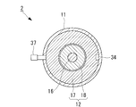
- FIG. 3 is a cross-sectional view of the multistage compressor taken along line III-III in FIG. It is a longitudinal cross-sectional view which shows another example of a shape of an injection nozzle.
- FIG. 1 is a schematic configuration diagram of a refrigeration system according to an embodiment of the present invention.
- the refrigeration system 1 is, for example, for a store showcase, but may be for other uses.
- a multistage compressor 2, a condenser 3, a gas-liquid separator 4, and an evaporator 5 are connected to the refrigerant passages 7a, 7b, 7c, 7d in this order to perform refrigeration / refrigeration operation Is configured to do.
- the refrigerant passages 7b and 7c are provided with expansion valves 8 and 9 for automatically adjusting the pressure and the flow rate of the refrigerant, respectively.
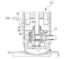
- FIG. 2 is a longitudinal sectional view of the multistage compressor 2.
- the multistage compressor 2 has a known basic structure. As shown in FIG. 1 and FIG. 2, the multistage compressor 2 includes a substantially cylindrical and sealed container-like housing 11 disposed with its axial direction oriented in the vertical direction.
- the electric motor 12 is installed in the central portion in the axial direction inside the housing 11, and the rotary compressor 13 (lower stage compression mechanism) is installed below the electric motor 12, that is, below the housing 11.
- the scroll compressor 14 (high stage side compression mechanism) is installed on the upper side, that is, on the upper part of the housing 11.
- the rotary compressor 13 and the scroll compressor 14 are coaxially driven by a main shaft 16 axially supported along the central axis of the housing 11.
- the electric motor 12 includes a stator 17 (stator) fixed to the inner peripheral surface of the housing 11 and a rotor 18 (rotor) positioned on the inner peripheral side of the stator 17 and integrally rotating with the main shaft 16 A coil 17 a is wound around the stator 17.
- stator 17 stator
- rotor 18 rotor
- cranks 16a and 16b eccentrically formed at both ends of the main shaft 16 are eccentrically inserted into the rotor 20 of the rotary compressor 13 and the orbiting scroll 22 of the scroll compressor 14, respectively.
- the electric motor 12 operates and the main shaft 16 rotates
- the rotor 20 of the rotary compressor 13 eccentrically rotates inside the eccentric cylinder 21 and the orbiting scroll 22 of the scroll compressor 14 orbits and revolves with respect to the fixed scroll 23 .
- a refrigerant suction pipe 26 communicating with the suction port 25 of the rotary compressor 13 is provided on the lower side surface of the housing 11, and a refrigerant discharge pipe 29 communicating with the discharge port 27 of the scroll compressor 14 and the discharge chamber 28 It is provided.
- the refrigerant passage 7 d shown in FIG. 1 is connected to the refrigerant suction pipe 26, and the refrigerant passage 7 a shown in FIG. 1 is connected to the refrigerant discharge pipe 29.
- the refrigerant discharge pipe 29 is provided with a refrigerant temperature sensor 30.
- the refrigerant temperature sensor 30 indirectly detects the operating temperature of the electric motor 12 by detecting the temperature of the compressed refrigerant discharged from the scroll compressor 14.
- the place where the electric motor 12 is installed in the housing 11 is the intermediate pressure area M, and when the multistage compressor 2 is in operation, it becomes a place where the intermediate pressure refrigerant primarily compressed by the rotary compressor 13 is filled.
- a predetermined amount of lubricating oil O is enclosed in the bottom of the housing 11.
- an oil supply pump 33 which is rotationally driven by the lower end of the main shaft 16, is installed so as to be submerged below the oil surface of the lubricating oil O.
- lubricating oil O passes through an oil supply passage (not shown), which is bored in the main shaft 16 along the axial direction, to a required lubrication point of the rotary compressor 13 and the scroll compressor 14. Refueled.
- the oil level of the lubricating oil O is H1 when the electric motor 12 is stopped, but when the electric motor 12 operates and the refrigerant flows in the housing 11, the refrigerant is mixed with the lubricating oil O so that H2 To rise.
- one or more return oil passages (stator cut) 34 are provided between the stator 17 of the electric motor 12 and the housing 11, and the scroll compression at the top of the housing 11 is made.
- the lubricating oil O supplied to the machine 14 flows down to the lower part of the housing 11 through the return oil passage 34.
- a horizontal straight pipe-like injection nozzle 37 is installed so as to face the electric motor 12.
- the position (height) of the inner opening 37a inside the housing 11 of the injection nozzle 37 corresponds to the flow direction of the intermediate pressure refrigerant flowing upward from below in the housing 11 when the multi-stage compressor 2 operates.
- the height is substantially the same as the end of the electric motor 12 on the upstream side, that is, near the lower end of the electric motor 12.
- the circumferential position of the injection nozzle 37 with respect to the housing 11 is deviated from the position of the return oil passage 34 where the lubricating oil O flows down from the upper part to the lower part in the housing 11 in plan view of the housing 11.
- Position For example, in the case where only one return oil passage 34 is provided, it is preferable to dispose the injection nozzle 37 on the opposite side in the circumferential direction 180 degrees with respect to the position of the return oil passage 34.
- the height of the inner opening 37 a of the injection nozzle 37 should be higher than the operating oil surface height H 2 of the lubricating oil O injected into the housing 11.
- the height of the outer opening 37b of the injection nozzle 37 should be at least higher than the stop oil surface height H1 of the lubricating oil O, preferably the operation oil surface height H2.
- the injection nozzle 37 may be formed in a bent (curved) shape or the like so that the outer opening 37b is higher than the opening 37b.
- a first refrigerant supply passage 41 branched from the refrigerant passage 7 b (condensed refrigerant passage) is connected to the injection nozzle 37.
- the refrigerant passage 7b branched from the first refrigerant supply passage 41 is a passage through which a part of the compressed refrigerant condensed and cooled in the condenser 3 flows to the gas-liquid separator 4 as described later.
- the first refrigerant supply passage 41 includes, in order from the refrigerant passage 7b side, an electromagnetic valve 42 (on-off valve) for opening and closing the first refrigerant supply passage 41, an expansion valve 43 for automatically adjusting the pressure and flow rate of the refrigerant, A check valve 44 is provided to prevent the backflow of the refrigerant toward the passage 7b.
- a second refrigerant supply passage 46 extending from the liquid surface space 4 a of the gas-liquid separator 4 is connected between the expansion valve 43 and the check valve 44 in the middle of the first refrigerant supply passage 41. That is, the second refrigerant supply passage 46 extends from the space 4 a on the liquid surface of the gas-liquid separator 4 and is connected to the injection nozzle 37 through the first refrigerant supply passage 41. It is also conceivable to provide an on-off valve, a flow rate adjustment valve or the like in the second refrigerant supply passage 46.
- a control unit 48 that controls the opening and closing of the solenoid valve 42 is provided.
- the control unit 48 opens the solenoid valve 42 when the operating temperature of the electric motor 12 of the multistage compressor 2 reaches a predetermined threshold temperature (for example, 120 ° C.).
- the operating temperature of the electric motor 12 is indirectly detected by the refrigerant temperature sensor 30 provided in the refrigerant discharge pipe 29 of the multistage compressor 2. That is, the refrigerant temperature sensor 30 detects the temperature of the compressed refrigerant discharged from the scroll compressor 14 and inputs the temperature signal S1 to the control unit 48 as the operation temperature signal of the electric motor 12.
- the control unit 48 sends an open / close signal S2 to the solenoid 42a of the solenoid valve 42 to open / close the solenoid valve 42.
- the refrigerant supply unit 50 is configured to include the first refrigerant supply passage 41, the second refrigerant supply passage 46, the solenoid valve 42, the control unit 48, and the refrigerant temperature sensor 30.
- the refrigerant supply unit 50 extracts the gas phase component and the liquid phase component of the compressed refrigerant discharged from the scroll compressor 14 of the multistage compressor 2 and selects these as the injection nozzle 37 of the multistage compressor 2 as an injection refrigerant. Supply.
- the injection refrigerant injected from the injection nozzle 37 is injected near the lower end of the coil 17 a of the stator 17 of the electric motor 12.
- the refrigeration system 1 and the multistage compressor 2 configured as described above operate as follows.
- the electric motor 12 is activated and the main shaft 16 is rotated, the rotor 20 of the rotary compressor 13 is eccentrically rotated inside the eccentric cylinder 21, and the refrigerant suction provided on the lower side surface of the housing 11 from the refrigerant passage 7d shown in FIG.
- Gas refrigerant is drawn in via a pipe 26 (see FIG. 2).
- the gas refrigerant is primarily compressed by the rotary compressor 13 and discharged to the intermediate pressure area M where the electric motor 12 is installed.
- the orbiting scroll 22 orbits relative to the fixed scroll 23, and the intermediate pressure refrigerant filled in the intermediate pressure area M is drawn from the suction port (not shown) It is compressed.
- a high-temperature, high-pressure compressed refrigerant is generated and discharged from the refrigerant discharge pipe 29 provided in the upper part of the housing 11, and is supplied to the refrigerant passage 7a shown in FIG.
- the high temperature / high pressure compressed refrigerant compressed in two stages by the multistage compressor 2 as described above flows through the refrigerant passage 7a to the condenser 3, where it exchanges heat with the air blown by the condenser fan 3a.
- the compressed refrigerant is cooled and condensed, and when it passes through the refrigerant passage 7b in a gas-liquid mixed state in which a gas phase refrigerant (gas refrigerant) and a liquid phase refrigerant (liquid refrigerant) are mixed.
- the flow rate and pressure are automatically adjusted by the expansion valve 8 and flow to the gas-liquid separator 4.
- the compressed refrigerant in the gas-liquid mixed state that has flowed to the gas-liquid separator 4 is separated into gas refrigerant and liquid refrigerant, and when the liquid refrigerant among them passes through the refrigerant passage 7c, the flow rate and pressure by the expansion valve 9 Are automatically adjusted and flow to the evaporator 5, where they exchange heat with the air blown by the evaporator fan 5a.
- the liquid refrigerant is evaporated (vaporized) to become a gas refrigerant, which is again drawn into the multistage compressor 2 through the refrigerant passage 7d and compressed, and similarly circulates through the refrigerant passages 7a to 7d.
- the evaporator 5 is cooled by the heat of vaporization of the liquid refrigerant, and is blown by the evaporator fan 5a to exchange heat with the low temperature evaporator 5, and the cold air is used for refrigeration and refrigeration.
- the control unit 48 of the refrigerant supply unit 50 refers to the temperature signal S1 of the compressed refrigerant input from the refrigerant temperature sensor 30, and the temperature of the compressed refrigerant, that is, the indirect operating temperature of the electric motor 12 is a predetermined threshold temperature (for example, The electromagnetic valve 42 is closed until the temperature reaches 120 ° C., and the electric motor 12 is cooled by the injection of only the gas refrigerant as described above.
- the control unit 48 transmits an open / close signal S2 to open the solenoid valve 42.
- a part of the compressed refrigerant (condensed refrigerant) containing a large amount of liquid phase flowing through the refrigerant passage 7 a is extracted from the first refrigerant supply passage 41 and supplied from the injection nozzle 37 to the electric motor 12 as the injection refrigerant.
- the pressure and flow rate of the injection refrigerant are automatically adjusted by the expansion valve 43. For this reason, the cooling by the injection of the liquid refrigerant or the gas-liquid mixed refrigerant with a high cooling effect of the electric motor 12 is performed.
- the gas phase component and the liquid phase component of the compressed refrigerant discharged from the scroll compressor 14 of the multistage compressor 2 are selectively supplied to the injection nozzle 37 by the refrigerant supply unit 50, and the injection nozzle 37 It is injected to 12. That is, the gas refrigerant or the liquid refrigerant can be selectively injected to the electric motor 12. Alternatively, the gas refrigerant and the liquid refrigerant can be mixed and injected to the electric motor 12.
- the operation is performed by the coil 17a of the electric motor 12 being overheated even under adverse conditions where the injection refrigerant always cools the electric motor 12 effectively and the refrigerant circulation amount decreases or the motor efficiency decreases. It is possible to prevent interruption and expand the operable range.
- the refrigerant supply unit 50 indirectly detects the temperature of the compressed refrigerant discharged from the multistage compressor 2 with the refrigerant temperature sensor 30, and inputs this refrigerant temperature to the control unit 48 as the temperature of the electric motor 12 (coil 17a). , Opening and closing control of the solenoid valve 42.
- the control unit 48 inputs this refrigerant temperature to the control unit 48 as the temperature of the electric motor 12 (coil 17a). , Opening and closing control of the solenoid valve 42.
- the position (height) of the inner opening 37 a inside the housing 11 of the injection nozzle 37 provided in the housing 11 is the electric motor on the upstream side in the flow direction of the intermediate pressure refrigerant in the housing 11. It is near the end of the motor 12, that is, near the lower part of the electric motor 12 in the present embodiment.
- the injection refrigerant injected from the injection nozzle 37 in the vicinity of the lower end of the electric motor 12 rides on the flow of the intermediate pressure refrigerant flowing in the intermediate pressure area M inside the housing 11 and the opposite end of the electric motor 12 ( It flows toward the upper end). Therefore, the electric motor 12 can be uniformly cooled.
- the liquid refrigerant injection refrigerant injected from the injection nozzle 37 tries to stay around the electric motor 12 by gravity.
- the speed of rising inside the housing 11 is reduced by the pressure refrigerant flow.
- the liquid refrigerant can be satisfactorily vaporized by the operation heat of the electric motor 12, and there is no possibility that the liquid refrigerant is wound up by the rotation of the electric motor 12 and sucked into the scroll compressor 14 as it is. Can prevent the liquid refrigerant from being compressed.
- the injection refrigerant from the injection nozzle 37 into the housing 11 It can be suppressed that the lubricating oil O injected into the housing 11 is sprayed when the fuel is injected. For this reason, it is possible to prevent the lubricating oil O from being blown up in the housing 11 and sucked as it is into the scroll compressor 14 and discharged to the outside of the multistage compressor 2.
- the multistage compressor 2 since the height of the outer opening 37b of the injection nozzle 37 outside the housing 11 is higher than the stop oil level H1 of the lubricating oil O, the multistage compressor 2 is shipped or installed, etc. In the above, it is possible to prevent the lubricating oil O from flowing out from the outer opening 37b.
- the circumferential position of the injection nozzle 37 with respect to the housing 11 is a position deviated from the return oil passage 34 where the lubricating oil O flows from the upper part to the lower part in the housing 11 in plan view of the housing 11 (see FIG. 3). ing. Therefore, the lubricating oil O flowing down from the upper portion in the housing 11 during the operation of the multistage compressor 2 does not hit the flow of the injection refrigerant injected from the injection nozzle 37 into the housing 11. Therefore, the lubricating oil O is prevented from being blown up in the housing 11, and the blown-out lubricating oil O is sucked as it is to the scroll compressor 14 and is prevented from being discharged to the outside of the multistage compressor 2 to thereby perform scroll compression. Machine 14 can be protected.
- the multistage compressor 2 As described above, according to the multistage compressor 2 according to the above embodiment and the refrigeration system 1 including the same, it is possible to prevent the liquid compression in the scroll compressor 14 which is the high stage side compression mechanism, and to prevent The electric motor 12 can be always cooled effectively to expand the operable range.
- the rotary compressor 13 is used as the lower stage compression mechanism and the scroll compressor 14 is used as the higher stage compression mechanism, but other types of compression mechanisms may be used or the same type of compression may be used.
- a mechanism may be provided in series.
- the multistage compressor 2 is arrange
- solenoid valve 42 is provided only in the first refrigerant supply passage 41 in the above embodiment, a solenoid valve is also provided in the second refrigerant supply passage 46, and the injection by the gas refrigerant is not necessary.
- the second refrigerant supply passage 46 may be closed.
Abstract
L'objectif de la présente invention est de refroidir efficacement un moteur électrique à tout moment au moyen d'un réfrigérant d'injection et d'agrandir la plage de fonctionnement, tout en empêchant une compression de liquide, dans un mécanisme de compression côté étage supérieur dans un compresseur à plusieurs étages. Ce compresseur à plusieurs étages (2) est équipé : d'un boîtier de type contenant hermétique (11) ; d'un mécanisme de compression côté étage inférieur (13) et d'un mécanisme de compression côté étage supérieur (14) disposés à l'intérieur de ce boîtier (11) ; d'un moteur électrique (12) qui est disposé dans une zone de pression intermédiaire à l'intérieur du boîtier (11), et qui entraîne le mécanisme de compression côté étage inférieur (13) et le mécanisme de compression côté étage supérieur (14) ; d'une buse d'injection (37) disposée de manière à pénétrer dans le boîtier (11) et faisant face au moteur électrique ; et d'une unité d'alimentation en réfrigérant (50), qui extrait la partie de phase gazeuse et la partie de phase liquide du réfrigérant comprimé évacué par le mécanisme de compression côté étage supérieur (14), et qui fournit sélectivement ledit réfrigérant d'injection à la buse d'injection (37).
Priority Applications (2)
| Application Number | Priority Date | Filing Date | Title |
|---|---|---|---|
| EP16853322.2A EP3346134B1 (fr) | 2015-10-08 | 2016-08-04 | Compresseur à plusieurs étages et système de réfrigération équipé de ce dernier |
| CN201680057317.6A CN108138777A (zh) | 2015-10-08 | 2016-08-04 | 多级压缩机以及具备该多级压缩机的制冷系统 |
Applications Claiming Priority (2)
| Application Number | Priority Date | Filing Date | Title |
|---|---|---|---|
| JP2015-200271 | 2015-10-08 | ||
| JP2015200271A JP2017072099A (ja) | 2015-10-08 | 2015-10-08 | 多段圧縮機およびこれを備えた冷凍システム |
Publications (1)
| Publication Number | Publication Date |
|---|---|
| WO2017061167A1 true WO2017061167A1 (fr) | 2017-04-13 |
Family
ID=58487510
Family Applications (1)
| Application Number | Title | Priority Date | Filing Date |
|---|---|---|---|
| PCT/JP2016/072994 WO2017061167A1 (fr) | 2015-10-08 | 2016-08-04 | Compresseur à plusieurs étages et système de réfrigération équipé de ce dernier |
Country Status (4)
| Country | Link |
|---|---|
| EP (1) | EP3346134B1 (fr) |
| JP (1) | JP2017072099A (fr) |
| CN (1) | CN108138777A (fr) |
| WO (1) | WO2017061167A1 (fr) |
Cited By (3)
| Publication number | Priority date | Publication date | Assignee | Title |
|---|---|---|---|---|
| CN107294289A (zh) * | 2017-07-21 | 2017-10-24 | 福建雪人股份有限公司 | 一种制冷压缩机的电机冷却机构 |
| WO2019189315A1 (fr) * | 2018-03-30 | 2019-10-03 | ダイキン工業株式会社 | Compresseur, dispositif à cycle de réfrigération |
| CN111102190A (zh) * | 2019-11-25 | 2020-05-05 | 珠海格力节能环保制冷技术研究中心有限公司 | 一种压缩机、空调系统和控制方法 |
Families Citing this family (4)
| Publication number | Priority date | Publication date | Assignee | Title |
|---|---|---|---|---|
| EP3859233B1 (fr) * | 2018-09-28 | 2023-04-26 | Daikin Industries, Ltd. | Système de compression à étages multiples |
| CN110439808A (zh) * | 2019-08-30 | 2019-11-12 | 浙江正理生能科技有限公司 | 一种转子和涡旋耦合压缩机 |
| US11867181B2 (en) * | 2020-10-29 | 2024-01-09 | Bascom Hunter Technologies, Inc. | Refrigeration system having a compressor driven by a magnetic coupling |
| EP4197834B1 (fr) * | 2021-12-20 | 2024-05-08 | Schmitz Cargobull AG | Machine à réfrigérer de transport, coffre et procédé de fonctionnement d'une machine à réfrigérer de transport |
Citations (5)
| Publication number | Priority date | Publication date | Assignee | Title |
|---|---|---|---|---|
| JPH0367958A (ja) * | 1989-08-02 | 1991-03-22 | Daikin Ind Ltd | 冷凍装置 |
| JP2008163894A (ja) * | 2006-12-28 | 2008-07-17 | Mitsubishi Heavy Ind Ltd | 多段圧縮機 |
| JP2008286037A (ja) * | 2007-05-16 | 2008-11-27 | Fujitsu General Ltd | ロータリ圧縮機およびヒートポンプシステム |
| JP2009030484A (ja) * | 2007-07-25 | 2009-02-12 | Mitsubishi Heavy Ind Ltd | 多段圧縮機 |
| JP2015014195A (ja) * | 2013-07-03 | 2015-01-22 | 日立アプライアンス株式会社 | 冷凍サイクル |
Family Cites Families (5)
| Publication number | Priority date | Publication date | Assignee | Title |
|---|---|---|---|---|
| US6615598B1 (en) * | 2002-03-26 | 2003-09-09 | Copeland Corporation | Scroll machine with liquid injection |
| JP4614441B2 (ja) * | 2005-06-10 | 2011-01-19 | 日立アプライアンス株式会社 | スクロール圧縮機 |
| JP4859694B2 (ja) * | 2007-02-02 | 2012-01-25 | 三菱重工業株式会社 | 多段圧縮機 |
| WO2011033710A1 (fr) * | 2009-09-18 | 2011-03-24 | 三菱重工業株式会社 | Compresseur multi-étages |
| CN204532835U (zh) * | 2015-04-07 | 2015-08-05 | 珠海格力节能环保制冷技术研究中心有限公司 | 压缩机和空调系统 |
-
2015
- 2015-10-08 JP JP2015200271A patent/JP2017072099A/ja active Pending
-
2016
- 2016-08-04 EP EP16853322.2A patent/EP3346134B1/fr active Active
- 2016-08-04 CN CN201680057317.6A patent/CN108138777A/zh active Pending
- 2016-08-04 WO PCT/JP2016/072994 patent/WO2017061167A1/fr active Application Filing
Patent Citations (5)
| Publication number | Priority date | Publication date | Assignee | Title |
|---|---|---|---|---|
| JPH0367958A (ja) * | 1989-08-02 | 1991-03-22 | Daikin Ind Ltd | 冷凍装置 |
| JP2008163894A (ja) * | 2006-12-28 | 2008-07-17 | Mitsubishi Heavy Ind Ltd | 多段圧縮機 |
| JP2008286037A (ja) * | 2007-05-16 | 2008-11-27 | Fujitsu General Ltd | ロータリ圧縮機およびヒートポンプシステム |
| JP2009030484A (ja) * | 2007-07-25 | 2009-02-12 | Mitsubishi Heavy Ind Ltd | 多段圧縮機 |
| JP2015014195A (ja) * | 2013-07-03 | 2015-01-22 | 日立アプライアンス株式会社 | 冷凍サイクル |
Cited By (7)
| Publication number | Priority date | Publication date | Assignee | Title |
|---|---|---|---|---|
| CN107294289A (zh) * | 2017-07-21 | 2017-10-24 | 福建雪人股份有限公司 | 一种制冷压缩机的电机冷却机构 |
| WO2019189315A1 (fr) * | 2018-03-30 | 2019-10-03 | ダイキン工業株式会社 | Compresseur, dispositif à cycle de réfrigération |
| JP2019183838A (ja) * | 2018-03-30 | 2019-10-24 | ダイキン工業株式会社 | 圧縮機、冷凍サイクル装置 |
| CN111936747A (zh) * | 2018-03-30 | 2020-11-13 | 大金工业株式会社 | 压缩机、冷冻循环装置 |
| CN111936747B (zh) * | 2018-03-30 | 2022-11-01 | 大金工业株式会社 | 压缩机、冷冻循环装置 |
| CN111102190A (zh) * | 2019-11-25 | 2020-05-05 | 珠海格力节能环保制冷技术研究中心有限公司 | 一种压缩机、空调系统和控制方法 |
| CN111102190B (zh) * | 2019-11-25 | 2024-01-09 | 珠海格力节能环保制冷技术研究中心有限公司 | 一种压缩机、空调系统和控制方法 |
Also Published As
| Publication number | Publication date |
|---|---|
| JP2017072099A (ja) | 2017-04-13 |
| EP3346134A1 (fr) | 2018-07-11 |
| CN108138777A (zh) | 2018-06-08 |
| EP3346134B1 (fr) | 2019-10-09 |
| EP3346134A4 (fr) | 2018-11-07 |
Similar Documents
| Publication | Publication Date | Title |
|---|---|---|
| WO2017061167A1 (fr) | Compresseur à plusieurs étages et système de réfrigération équipé de ce dernier | |
| JP4859694B2 (ja) | 多段圧縮機 | |
| US7013672B2 (en) | Refrigerant cycling device | |
| US8366406B2 (en) | Multi-stage compressor | |
| JP2009127902A (ja) | 冷凍装置及び圧縮機 | |
| JPWO2018096825A1 (ja) | インジェクション機能を備えた圧縮機 | |
| KR20110074711A (ko) | 냉동장치 | |
| KR20110074707A (ko) | 냉동장치 | |
| JP4114337B2 (ja) | 冷凍装置 | |
| KR101332478B1 (ko) | 냉동장치 | |
| JPH02230995A (ja) | ヒートポンプ用圧縮機及びその運転方法 | |
| KR102189168B1 (ko) | 압축기 조립체 및 그 제어 방법 그리고 냉각/가열 시스템 | |
| CN112752934B (zh) | 多级压缩系统 | |
| KR101268207B1 (ko) | 냉동장치 | |
| JP2010060202A (ja) | 冷凍機用電動機における冷却構造 | |
| JP2008275291A (ja) | 給湯装置 | |
| US10436202B2 (en) | Scroll compressor and refrigeration cycle apparatus | |
| JP5877331B2 (ja) | スクロール圧縮機を備えた冷凍装置 | |
| JP7047416B2 (ja) | 空気調和機 | |
| JP2006125794A (ja) | 冷凍サイクル装置 | |
| JP2009180491A (ja) | ターボ冷凍機 | |
| JP2008145100A (ja) | 冷凍装置 |
Legal Events
| Date | Code | Title | Description |
|---|---|---|---|
| 121 | Ep: the epo has been informed by wipo that ep was designated in this application |
Ref document number: 16853322 Country of ref document: EP Kind code of ref document: A1 |
|
| NENP | Non-entry into the national phase |
Ref country code: DE |
|
| WWE | Wipo information: entry into national phase |
Ref document number: 2016853322 Country of ref document: EP |