WO2017061052A1 - 船舶 - Google Patents
船舶 Download PDFInfo
- Publication number
- WO2017061052A1 WO2017061052A1 PCT/JP2015/078826 JP2015078826W WO2017061052A1 WO 2017061052 A1 WO2017061052 A1 WO 2017061052A1 JP 2015078826 W JP2015078826 W JP 2015078826W WO 2017061052 A1 WO2017061052 A1 WO 2017061052A1
- Authority
- WO
- WIPO (PCT)
- Prior art keywords
- residential area
- main body
- ship
- hull
- cylinder
- Prior art date
- Legal status (The legal status is an assumption and is not a legal conclusion. Google has not performed a legal analysis and makes no representation as to the accuracy of the status listed.)
- Ceased
Links
Images



Classifications
-
- B—PERFORMING OPERATIONS; TRANSPORTING
- B63—SHIPS OR OTHER WATERBORNE VESSELS; RELATED EQUIPMENT
- B63B—SHIPS OR OTHER WATERBORNE VESSELS; EQUIPMENT FOR SHIPPING
- B63B15/00—Superstructures, deckhouses, wheelhouses or the like; Arrangements or adaptations of masts or spars, e.g. bowsprits
-
- B—PERFORMING OPERATIONS; TRANSPORTING
- B63—SHIPS OR OTHER WATERBORNE VESSELS; RELATED EQUIPMENT
- B63B—SHIPS OR OTHER WATERBORNE VESSELS; EQUIPMENT FOR SHIPPING
- B63B29/00—Accommodation for crew or passengers not otherwise provided for
- B63B29/02—Cabins or other living spaces; Construction or arrangement thereof
-
- B—PERFORMING OPERATIONS; TRANSPORTING
- B63—SHIPS OR OTHER WATERBORNE VESSELS; RELATED EQUIPMENT
- B63B—SHIPS OR OTHER WATERBORNE VESSELS; EQUIPMENT FOR SHIPPING
- B63B39/00—Equipment to decrease pitch, roll, or like unwanted vessel movements; Apparatus for indicating vessel attitude
Definitions
- This invention relates to a ship.
- Fin stabilizers, anti-pitching fins, and the like are known as a means for reducing the vibration of the hull.
- fin stabilizers and anti-pitching fins increase the hull resistance and significantly reduce the propulsion performance.
- Patent Document 1 describes a high-speed boat in which the superstructure is separated from the hull.
- This high speed boat includes a shock absorber and hydrofoil.
- the shock absorber is disposed between the upper structure and the hull to absorb the vibration and impact of the hull and suppress the propagation of the vibration and impact of the hull to the upper structure.
- the hydrofoil is attached to the lower end of a leg that extends downward from the superstructure. This hydrofoil can adjust the flying height of the superstructure by changing the elevation angle of the flap.
- An object of the present invention is to provide a ship that can improve the ride comfort without separating the hull and the upper structure vertically and without lowering the propulsion performance.
- the ship includes a hull, an upper structure formed above the upper deck of the hull, and a vibration reduction disposed in at least one of the hull and the upper structure.
- a residential area The attenuating residential area is disposed between a pair of decks adjacent in the vertical direction.
- the volume-reducing housing area is a housing area body that is spaced apart from the pair of decks, and a support that supports the housing area body so as to be movable relative to at least one of the pair of decks.
- An apparatus By comprising in this way, a residential area main body can move relatively with respect to a deck with a support apparatus. Therefore, it is possible to suppress the vibration and impact of the hull from being transmitted to the living area main body via the deck.
- the ride comfort can be improved without separating the hull and the upper structure vertically and without lowering the propulsion performance. Furthermore, by providing the above-mentioned reduced-swelling residential area, it is possible to partially reduce the necessary places in the ship. Therefore, it is possible to easily reduce the residential area etc. even in a large passenger ship or the like.
- the ship is configured such that the support device in the first aspect is supported by at least one of the pair of decks and is capable of extending and contracting vertically and the main body of the living area.
- You may further provide the control apparatus which controls the expansion-contraction of the said cylinder.
- a cylinder can be expanded-contracted by a control apparatus so that the shaking of a deck may be canceled, for example. Therefore, the swaying of the residential area main body can be further suppressed.
- the ship may be provided with the spring that is supported by at least one of the pair of decks and can extend and contract in the vertical direction in the first or second aspect.
- the spring that is supported by at least one of the pair of decks and can extend and contract in the vertical direction in the first or second aspect.
- the ship may include a cover member that covers the support device in any one of the first to third aspects. By comprising in this way, it can suppress that the worker etc. who are on the deck contact the cylinder, the spring, etc. which are operating.
- the ride quality can be improved without separating the hull and the upper structure vertically and without lowering the propulsion performance.
- FIG. 2 It is a side view which shows schematic structure of the ship in embodiment of this invention. It is an enlarged view which shows schematic structure of the dampening residential area in embodiment of this invention. It is a perspective view of the dampening residential area in embodiment of this invention. It is a side view equivalent to FIG. 2 in the 1st modification of embodiment of this invention. It is a side view equivalent to FIG. 2 in the 2nd modification of embodiment of this invention. It is a side view equivalent to FIG. 2 in the 3rd modification of embodiment of this invention.
- FIG. 1 is a side view showing a schematic configuration of a ship according to an embodiment of the present invention.
- the ship 1 in this embodiment is a large passenger ship such as a cruise liner having a total length exceeding 100 m.
- FIG. 1 illustrates a case where two decks 5 are provided inside the superstructure 3.
- a cabin, a bridge, and the like are provided inside the superstructure 3.
- An exhaust chimney 7 is provided on the upper superstructure deck 6 disposed at the top of the superstructure 3 so as to protrude upward.
- the hull 2 includes a plurality of decks 5 that are spaced apart in the vertical direction, like the superstructure 3, below the upper deck 4.
- the ship 1 further includes an anti-swaying residential area 9.
- the reduced-swelling residential area 9 forms a living space in which the influence of shaking and impact of the ship 1 is suppressed.
- This reduced-swelling residential area 9 is provided inside the ship 1.
- the attenuating residential area 9 is provided inside the superstructure 3 where the position of the center of gravity of the ship 1 that is less affected by the shaking of the hull 2 exists.
- the center of gravity of the ship 1 means the center of gravity of the ship 1 in the standard loading state.
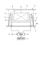
- FIG. 2 is an enlarged view showing a schematic configuration of an attenuating residential area in the embodiment of the present invention.
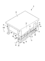
- FIG. 3 is a perspective view of an attenuating residential area in the embodiment of the present invention.
- the vibration reduction residential area 9 includes a residential area main body 10, a support device 11, and a boarding / exiting device 12 (see FIG. 3).
- the residential area main body 10 is disposed between a pair of decks 5 adjacent in the vertical direction.
- the residential area main body 10 is arranged to be separated from the pair of decks 5 by the support device 11.
- the residential area main body 10 in this embodiment is disposed between the upper deck 4 and the lowermost deck 5 of the superstructure 3.
- the living area main body 10 in this embodiment is formed in a hollow box shape.
- This box-shaped residential area main body 10 has an entrance 14 on its side surface 13. An occupant and a passenger can enter and leave the residential area main body 10 through the entrance 14.
- the support device 11 supports the residential area main body 10 so as to be movable relative to at least one of the pair of decks 5.
- the support device 11 in this embodiment includes a cylinder 15 and a control device 16 (see FIG. 2).
- the cylinder 15 is supported by at least one of the pair of decks 5 and is configured to be extendable in the vertical direction.
- the cylinder 15 is composed of, for example, a hydraulic cylinder (not shown).
- the cylinder 15 expands and contracts in accordance with a control command from the control device 16.
- the cylinder 15 supports, for example, a flange portion 17 formed on the upper portion of the residential area main body 10 from below. In this way, the cylinder 15 supporting the flange portion 17 formed on the upper part of the living area main body 10 is supported from below, so that the cylinder 15 having the largest stroke amount is used in a limited height space. It is possible.
- the residential area main body 10 is supported near its four corners by the four cylinders 15, for example.
- the four cylinders 15 expand and contract, the heights of the four corners of the living area main body 10 change based on the lower deck 5. That is, the residence main body 10 can be freely tilted (relatively movable) with respect to the deck 5.
- the control device 16 controls the expansion and contraction of the cylinder 15 so as to reduce the residence body 10.
- the control device 16 expands and contracts each cylinder 15 in a direction that cancels the shaking of the hull 2 based on a signal from the motion detection device S that detects the shaking of the hull 2.
- the control device 16 obtains the stroke amount of the cylinder 15 so that the residential area main body 10 remains stationary when the hull 2 is shaken. This stroke amount can be obtained by a predetermined mathematical formula, a map, or the like.
- the control device 16 outputs a signal for setting the cylinder 15 to the obtained stroke amount.
- the signal output from the motion detection device S may be input to the control device 16 through a low-pass filter for the purpose of waveform shaping.
- the stroke amount control of the cylinder 15 described above may be performed via a servo amplifier.
- the ship 1 further includes a cover member C.
- the cover member C covers the cylinder 15 from the outside so that an occupant or a passenger does not contact the cylinder 15.
- the cover member C in this embodiment covers each cylinder 15 from the outside of the reduced-swelling residential area 9. More specifically, the cover member C is attached so as to extend between the flange portion 17 and the deck 5 (upper deck 4) that supports the cylinder 15.
- the cover member C can be formed, for example, in a bellows shape so that it can be deformed according to the expansion and contraction of the cylinder 15.
- the bellows-like cover member C has been described.
- the cover member C is not limited to the shape described above. For example, you may make it provide a wall (it shows with a broken line in FIG. 2) as the cover member C in the outer side of the cylinder 15 of the vibration reduction living area 9.
- the boarding / alighting device 12 is a device for facilitating boarding / alighting of passengers and passengers to / from the residential area main body 10.
- the getting-on / off device 12 includes a slope portion 18, an upper plate portion 19, and an operation panel B.
- the slope portion 18 is formed so as to be inclined between the entrance 14 of the residential area main body 10 and the lower deck 5.
- the slope portion 18 in this embodiment extends along the side surface 13 of the residential area main body 10 where the entrance 14 is formed.
- the slope portion 18 is connected to the deck 5 via a hinge 20 or the like. That is, the inclination angle of the slope portion 18 with respect to the deck 5 is variable.
- the extending direction of the slope portion 18 is not limited to the above direction.
- a stairs may be provided instead of the slope portion 18.
- the upper plate portion 19 extends outward from the lower edge of the entrance 14. In other words, the upper plate portion 19 extends in a direction away from the side surface 13.
- the upper plate portion 19 in this embodiment is connected to the residential area main body 10 and the slope portion 18 via a hinge 20 or the like. That is, the relative angle between the upper plate portion 19 and the residential area main body 10 and the slope portion 18 is variable. That is, the slope portion 18 and the upper plate portion 19 can follow the displacement even if the living area main body 10 is inclined due to the expansion and contraction of the cylinder 15.
- a handrail 21 is provided on each of the slope portion 18 and the upper plate portion 19 described above.
- the operation panel B is disposed near the entrance 18a of the slope portion 18.
- the operation panel B includes a stop button B1 and an operation button B2.
- the stop button B ⁇ b> 1 is an operation button for temporarily stopping the vibration reduction operation by the support device 11 when an occupant or a passenger gets on or off the residential area main body 10.
- the operation button B2 is an operation button for canceling the stop state of the temporary vibration reduction operation.
- the stop button B1 and the operation button B2 are connected to the control device 16, respectively.
- This operation panel B is also provided in the interior of the residential area main body 10. That is, the occupant or the passenger can stop the vibration reduction operation when getting on and off the residential area main body 10. Therefore, an occupant or a passenger can safely get on and off the residential area main body 10.
- the living body 10 can be moved relative to the deck 5 by the support device 11. Therefore, it is possible to suppress the shaking and impact of the hull 2 from being transmitted to the residential area main body 10 via the deck 5. As a result, the ride comfort can be improved without separating the hull 2 and the superstructure 3 up and down and without lowering the propulsion performance.
- the ship 1 according to the above-described embodiment can expand and contract the cylinder 15 by the control device 16 so as to cancel the shaking of the deck 5. Therefore, it is possible to further suppress the shaking of the residential area main body 10. Furthermore, the ship 1 of the embodiment described above includes a cover member C that covers the support device 11 from the outside. Therefore, it can suppress that the worker etc. who are on the deck 5 contact the support apparatus 11. FIG.
- the vibration reduction residence area 9 it is possible to partially reduce the necessary parts in the ship. Therefore, it is possible to easily reduce the residential area etc. even in a large passenger ship or the like. Further, the reduced-swelling residential area 9 can be arranged not only inside the upper structure 3 but also inside the hull 2. Therefore, compared with the case where an upper structure is separated from a hull and an upper structure is shaken, the arrangement
- FIG. 4 is a side view corresponding to FIG. 2 in the first modification of the embodiment of the present invention.
- the support device 11 includes the cylinder 15 has been described.
- the case where the support apparatus 11 was supported only by the lower deck 5 among a pair of decks 5 was demonstrated.
- the configuration of the support device 11 is not limited to the configuration of the above-described embodiment.
- the support device 11 may use a coil spring 22 (spring) instead of the cylinder 15.
- the coil spring 22 may be attached so as to cross between the upper deck 5 and the residential area main body 10 and between the lower deck 5 and the residential area main body 10, respectively.
- these coil springs 22 are covered with a cover member C (hereinafter, the same applies to the second and third modifications).
- FIG. 4 illustrates the case where only the coil spring 22 is used.
- a damper (not shown) that absorbs the vibration of the coil spring 22 may be provided.
- the coil spring 22 can absorb the shaking and vibration of the deck 5 caused by the shaking and vibration of the hull 2, and the living body 10 can be prevented from shaking. As a result, it is possible to suppress shaking and impact from being transmitted from the deck 5 to the residential area body 10 with a simpler configuration than when the cylinder 15 is used.
- FIG. 5 is a side view corresponding to FIG. 2 in a second modification of the embodiment of the present invention.
- FIG. 6 is a side view corresponding to FIG. 2 in a third modification of the embodiment of the present invention.
- the first modification of the above-described embodiment the case where the residential area main body 10 is supported only by the coil spring 22 is illustrated.
- the configuration using the coil spring 22 for the support device 11 is not limited to the configuration of the above-described embodiment or the first modification.
- a cylinder 15 is provided between the lower deck 5 and the residential area main body 10, and the coil spring 22 is provided between the upper deck 5 and the residential area main body 10. It may be provided.
- a coil spring 22 is provided between the lower deck 5 and the residential area main body 10, and the cylinder 15 is provided between the upper deck 5 and the residential area main body 10. It may be provided.
- the present invention is not limited to the above-described embodiments and modifications, and includes various modifications made to the above-described embodiments without departing from the spirit of the present invention. That is, the specific shapes, configurations, and the like given in the embodiment are merely examples, and can be changed as appropriate.
- the position where the reduced vibration residential area 9 is installed is not limited to the position of the center of gravity of the ship 1.
- the attenuating residential area 9 may be installed between a pair of decks 5 provided on the hull 2 or between a pair of decks 5 provided on the superstructure 3.
- the reduced-swing residential area 9 may be installed on the side closer to the bow than the center of gravity position, or on the side closer to the stern than the center of gravity position in the stern direction.
- one anti-vibration residential area 9 is provided in one ship 1 .
- the present invention is not limited to this configuration, and one ship 1 may be provided with a plurality of vibration reducing residential areas 9.
- the cylinder 15 may be used for the support device 11 only in the reduced-swing residential area 9 having a relatively high guest-grade according to the grade of the guest room provided in the reduced-swing residential area 9.
- the residential area main body 10 is supported by the cylinder 15 or the coil spring 22
- the residential area main body 10 may be connected to the deck 5 by a connecting portion (not shown) that can swing in both the bow-stern direction and the ship width direction.
- the cylinder 15 and the coil spring 22 may be provided around the connecting portion to reduce the vibration.
- the ship 1 is a passenger ship has been described as an example.
- the ship 1 is not limited to a passenger ship.
- This invention can be applied to ships such as passenger ships. According to the present invention, the ride comfort can be improved without separating the hull up and down and without lowering the propulsion performance.
Landscapes
- Chemical & Material Sciences (AREA)
- Engineering & Computer Science (AREA)
- Combustion & Propulsion (AREA)
- Mechanical Engineering (AREA)
- Ocean & Marine Engineering (AREA)
- Vibration Prevention Devices (AREA)
Abstract
船舶(1)は、船体(2)と、船体(2)の上甲板(4)よりも上方に形成された上部構造物(3)と、これら船体(1)および上部構造物(2)の少なくとも一方の内部に配置された減揺居住区(9)と、を備えている。減揺居住区(9)は、互いに上下方向に隣り合う一対の甲板(5)の間に配置され、これら一対の甲板(5)とは離間して配置された居住区本体(10)を備えている。減揺居住区(9)は、居住区本体(10)を、一対の甲板(5)の少なくとも一方に対して相対移動可能となるように支持する支持装置(11)を更に備えている。
Description
この発明は、船舶に関する。
船舶は、波浪等により船体が動揺することで乗り心地が悪化して乗員や乗客が船酔いしてしまう場合がある。
このような船体の動揺を低減する減揺手段としては、フィンスタビライザーやアンチピッチングフィンなどが知られている。しかし、フィンスタビライザーやアンチピッチングフィンは、船体抵抗が増加して推進性能が著しく低下してしまう。
このような船体の動揺を低減する減揺手段としては、フィンスタビライザーやアンチピッチングフィンなどが知られている。しかし、フィンスタビライザーやアンチピッチングフィンは、船体抵抗が増加して推進性能が著しく低下してしまう。
特許文献1には、上部構造物が船体と分離された高速艇が記載されている。この高速艇は、緩衝装置と水中翼とを備えている。緩衝装置は、上部構造物と船体との間に配置されて船体の動揺や衝撃を吸収して、上部構造物への船体の動揺や衝撃の伝搬を抑制している。水中翼は、上部構造物から下方に向かって延びる脚の下端部に取り付けられている。この水中翼は、そのフラップの仰角を変えて上部構造物の浮上量の調整が可能となっている。
上述した特許文献1に記載の減揺手段は、上部構造物全体を船体から分離する必要がある。そのため、例えば、全長が100m以上の旅客船などの大型の船舶に対して適用することが困難となっている。
この発明は、船体と上部構造物とを上下に分離せず、且つ、推進性能を低下させることなく、乗り心地を向上できる船舶を提供することを目的とする。
この発明は、船体と上部構造物とを上下に分離せず、且つ、推進性能を低下させることなく、乗り心地を向上できる船舶を提供することを目的とする。
この発明の第一態様によれば、船舶は、船体と、前記船体の上甲板よりも上方に形成された上部構造物と、これら船体および上部構造物の少なくとも一方の内部に配置された減揺居住区と、を備えている。前記減揺居住区は、上下方向に隣り合う一対の甲板の間に配置されている。前記減容居住区は、これら一対の甲板とは離間して配置された居住区本体と、前記居住区本体を、前記一対の甲板の少なくとも一方に対して相対移動可能となるように支持する支持装置と、を備える。
このように構成することで、支持装置によって居住区本体が甲板に対して相対移動できる。そのため、船体の動揺や衝撃が甲板を介して居住区本体に伝達されることを抑制できる。したがって、船体と上部構造物とを上下に分離せず、且つ、推進性能を低下させることなく、乗り心地を向上できる。
さらに、上記減揺居住区を備えることで、船舶の中で必要な箇所を部分的に減揺させることができる。そのため、大型の客船等においても容易に居住区等を減揺させることができる。
このように構成することで、支持装置によって居住区本体が甲板に対して相対移動できる。そのため、船体の動揺や衝撃が甲板を介して居住区本体に伝達されることを抑制できる。したがって、船体と上部構造物とを上下に分離せず、且つ、推進性能を低下させることなく、乗り心地を向上できる。
さらに、上記減揺居住区を備えることで、船舶の中で必要な箇所を部分的に減揺させることができる。そのため、大型の客船等においても容易に居住区等を減揺させることができる。
この発明の第二態様によれば、船舶は、第一態様における支持装置が、前記一対の甲板の少なくとも一方に支持されて上下方向に伸縮可能なシリンダと、前記居住区本体を減揺するように前記シリンダの伸縮を制御する制御装置を更に備えていてもよい。
このように構成することで、例えば、甲板の動揺を打ち消すように制御装置によってシリンダを伸縮することができる。したがって、居住区本体の動揺をより一層抑制することができる。
このように構成することで、例えば、甲板の動揺を打ち消すように制御装置によってシリンダを伸縮することができる。したがって、居住区本体の動揺をより一層抑制することができる。
この発明の第三態様によれば、船舶は、第一又は第二態様における支持装置が、前記一対の甲板の少なくとも一方に支持されて上下方向に伸縮可能なスプリングを備えていてもよい。
このように構成することで、スプリングによって、甲板の動揺を吸収することができる。したがって、簡単な構成で甲板から伝達される居住区本体への動揺や衝撃を抑制できる。
このように構成することで、スプリングによって、甲板の動揺を吸収することができる。したがって、簡単な構成で甲板から伝達される居住区本体への動揺や衝撃を抑制できる。
この発明の第四態様によれば、船舶は、第一から第三態様の何れか一つの態様において、前記支持装置を覆うカバー部材を備えていてもよい。
このように構成することで、甲板の上に居る作業員等が作動中のシリンダやスプリングなどに接触することを抑制できる。
このように構成することで、甲板の上に居る作業員等が作動中のシリンダやスプリングなどに接触することを抑制できる。
上記船舶によれば、船体と上部構造物とを上下に分離せず、且つ、推進性能を低下させることなく、乗り心地を向上できる。
(実施形態)
図1は、この発明の実施形態における船舶の概略構成を示す側面図である。
この実施形態における船舶1は、全長が100mを超えるクルーズ客船等の大型客船である。
図1は、この発明の実施形態における船舶の概略構成を示す側面図である。
この実施形態における船舶1は、全長が100mを超えるクルーズ客船等の大型客船である。
図1に示すように、この実施形態の船舶1は、大型客船であるため船体2の上甲板4の上に、大型の船楼(上部構造物)3が設けられている。この船楼3は、少なくとも一つの甲板5を有している。図1では船楼3の内部に甲板5が2つ設けられている場合を例示している。船楼3の内部には、客室やブリッジ等が設けられている。船楼3の最も上に配置された上部船楼甲板6の上には、上方に向かって突出するように排気用の煙突7が設けられている。
船体2は、上甲板4よりも下に、船楼3と同様に上下方向に離間した複数の甲板5を備えている。
船体2は、上甲板4よりも下に、船楼3と同様に上下方向に離間した複数の甲板5を備えている。
船舶1は、減揺居住区9を更に備えている。減揺居住区9は、船舶1の揺れや衝撃の影響が抑制された居住空間等を形成する。この減揺居住区9は、船舶1の内部に設けられている。この実施形態における減揺居住区9は、船体2の動揺の影響が少ない船舶1の重心位置が存在する船楼3の内部に設けられている。船舶1の重心とは、船舶1の標準積み付け状態における重心を意味している。
図2は、この発明の実施形態における減揺居住区の概略構成を示す拡大図である。図3は、この発明の実施形態における減揺居住区の斜視図である。
図2、図3に示すように、減揺居住区9は、居住区本体10と、支持装置11と、乗降装置12(図3参照)と、を備えている。
居住区本体10は、上下方向に隣り合う一対の甲板5の間に配置されている。居住区本体10は、支持装置11によって、これら一対の甲板5とは離間して配置されている。この実施形態における居住区本体10は、上甲板4と、船楼3の一番下の甲板5との間に配置されている。この実施形態における居住区本体10は、中空の箱状に形成されている。この箱状の居住区本体10は、その側面13に乗降口14を有している。この乗降口14を介して乗員や乗客が居住区本体10に対して出入り可能となっている。
図2、図3に示すように、減揺居住区9は、居住区本体10と、支持装置11と、乗降装置12(図3参照)と、を備えている。
居住区本体10は、上下方向に隣り合う一対の甲板5の間に配置されている。居住区本体10は、支持装置11によって、これら一対の甲板5とは離間して配置されている。この実施形態における居住区本体10は、上甲板4と、船楼3の一番下の甲板5との間に配置されている。この実施形態における居住区本体10は、中空の箱状に形成されている。この箱状の居住区本体10は、その側面13に乗降口14を有している。この乗降口14を介して乗員や乗客が居住区本体10に対して出入り可能となっている。
支持装置11は、居住区本体10を一対の甲板5の少なくとも一方に対して相対移動可能となるように支持する。この実施形態における支持装置11は、シリンダ15と、制御装置16(図2参照)とを備えている。
シリンダ15は、一対の甲板5の少なくとも一方に支持されて上下方向に伸縮可能に構成されている。このシリンダ15は、例えば、油圧シリンダ等(図示せず)からなる。シリンダ15は、制御装置16からの制御指令に従って伸縮する。シリンダ15は、例えば、居住区本体10の上部に形成されたフランジ部17を下方から支持している。このように居住区本体10の上部に形成されたフランジ部17をシリンダ15が下方から支持することで、限られた高さの空間の中で、可能な限りストローク量の大きなシリンダ15を使用することが可能となっている。
この実施形態において、居住区本体10は、例えば、その4本のシリンダ15によって、その四隅の近くで支持されている。これら4本のシリンダ15が伸縮することで、下方の甲板5を基準として、居住区本体10の四隅の高さが変化する。つまり、居住区本体10は、甲板5に対して自在に傾斜させることが可能(相対移動可能)となっている。
制御装置16は、居住区本体10を減揺するようにシリンダ15の伸縮を制御する。この制御装置16は、船体2の動揺を検出する運動検出装置Sからの信号に基づいて、この船体2の動揺を打ち消す方向に各シリンダ15を伸縮させる。具体的には、制御装置16は、船体2が動揺したときに居住区本体10が静止状態を維持するようにシリンダ15のストローク量を求める。このストローク量は、予め定められた数式、マップ等によって求めることができる。制御装置16は、シリンダ15を、この求めたストローク量とするための信号を出力する。ここで、運動検出装置Sから出力される信号は、波形成形を行う目的でローパスフィルタを介してから制御装置16へ入力するようにしても良い。更に、上述したシリンダ15のストローク量の制御は、サーボアンプを介して行うようにしても良い。
船舶1は、カバー部材Cを更に備えている。
カバー部材Cは、乗員や乗客がシリンダ15に接触しないように、シリンダ15を外側から覆っている。この実施形態におけるカバー部材Cは、各シリンダ15を減揺居住区9の外側から覆っている。より具体的には、カバー部材Cは、フランジ部17と、シリンダ15を支持する甲板5(上甲板4)との間に渡るように取り付けられている。カバー部材Cは、シリンダ15の伸縮に応じて変形可能なように、例えば、蛇腹状に形成することができる。ここでは、蛇腹状のカバー部材Cを設ける場合について説明した。しかし、カバー部材Cは、上述した形状に限られない。例えば、減揺居住区9のシリンダ15の外側にカバー部材Cとして壁(図2中、破線で示す)を設けるようにしても良い。
カバー部材Cは、乗員や乗客がシリンダ15に接触しないように、シリンダ15を外側から覆っている。この実施形態におけるカバー部材Cは、各シリンダ15を減揺居住区9の外側から覆っている。より具体的には、カバー部材Cは、フランジ部17と、シリンダ15を支持する甲板5(上甲板4)との間に渡るように取り付けられている。カバー部材Cは、シリンダ15の伸縮に応じて変形可能なように、例えば、蛇腹状に形成することができる。ここでは、蛇腹状のカバー部材Cを設ける場合について説明した。しかし、カバー部材Cは、上述した形状に限られない。例えば、減揺居住区9のシリンダ15の外側にカバー部材Cとして壁(図2中、破線で示す)を設けるようにしても良い。
乗降装置12は、居住区本体10への乗員や乗客の乗降を容易にするための装置である。この乗降装置12は、スロープ部18と、上板部19と、操作盤Bと、を備えている。
スロープ部18は、居住区本体10の乗降口14と、下方の甲板5との間に渡って傾斜するように形成されている。この実施形態におけるスロープ部18は、乗降口14が形成されている居住区本体10の側面13に沿って延びている。スロープ部18は、甲板5に対してヒンジ20等を介して接続されている。つまり、スロープ部18は、甲板5に対して、その傾斜角度が可変とされている。ここで、スロープ部18が側面13に沿って形成される場合について説明した。しかし、スロープ部18の延びる方向は上記方向に限られない。さらに、スロープ部18に代えて階段を設けても良い。
スロープ部18は、居住区本体10の乗降口14と、下方の甲板5との間に渡って傾斜するように形成されている。この実施形態におけるスロープ部18は、乗降口14が形成されている居住区本体10の側面13に沿って延びている。スロープ部18は、甲板5に対してヒンジ20等を介して接続されている。つまり、スロープ部18は、甲板5に対して、その傾斜角度が可変とされている。ここで、スロープ部18が側面13に沿って形成される場合について説明した。しかし、スロープ部18の延びる方向は上記方向に限られない。さらに、スロープ部18に代えて階段を設けても良い。
上板部19は、乗降口14の下縁から外方に向かって延びている。言い換えれば、上板部19は、側面13から離間する方向に延びている。この実施形態における上板部19は、ヒンジ20等を介して居住区本体10、および、スロープ部18と接続されている。つまり、上板部19は、居住区本体10、および、スロープ部18との相対的な角度が可変となっている。つまり、スロープ部18、及び、上板部19は、シリンダ15の伸縮によって居住区本体10が傾いたとしても、その変位に追従することが可能となっている。
上述したスロープ部18と上板部19とには、それぞれ手摺21が設けられている。
上述したスロープ部18と上板部19とには、それぞれ手摺21が設けられている。
操作盤Bは、スロープ部18の入口18aの近くに配置されている。この操作盤Bは、停止ボタンB1と作動ボタンB2とを備えている。停止ボタンB1は、乗員や乗客が居住区本体10へ乗降する際に、一時的に支持装置11による減揺動作を停止させるための操作ボタンである。作動ボタンB2は、一時的な減揺動作の停止状態を解除するための操作ボタンである。これら停止ボタンB1と作動ボタンB2とは、それぞれ制御装置16に接続されている。この操作盤Bは、居住区本体10の内部にも同様のものが設けられている。つまり、乗員や乗客は、居住区本体10への乗降を行うときに減揺動作を停止させることができる。そのため、乗員や乗客は、安全に居住区本体10への乗降を行うことができる。
したがって、上述した実施形態によれば、支持装置11によって居住区本体10が甲板5に対して相対移動できる。そのため、船体2の動揺や衝撃が甲板5を介して居住区本体10に伝達されることを抑制できる。その結果、船体2と船楼3とを上下に分離せず、且つ、推進性能を低下させることなく、乗り心地を向上できる。
さらに、上述した実施形態の船舶1は、甲板5の動揺を打ち消すように制御装置16によってシリンダ15を伸縮することができる。そのため、居住区本体10の動揺をより一層抑制することができる。
さらに、上述した実施形態の船舶1は、支持装置11を外側から覆うカバー部材Cを備えている。そのため、甲板5の上に居る作業員等が支持装置11に接触することを抑制できる。
さらに、上述した実施形態の船舶1は、支持装置11を外側から覆うカバー部材Cを備えている。そのため、甲板5の上に居る作業員等が支持装置11に接触することを抑制できる。
さらに、上記減揺居住区9を備えることで、船舶の中で必要な箇所を部分的に減揺させることができる。そのため、大型の客船等においても容易に居住区等を減揺させることができる。さらに、上部構造物3の内部だけではなく船体2の内部にも減揺居住区9を配置できる。そのため、上部構造物を船体から分離して上部構造物を減揺する場合と比較して、船舶1内における減揺居住区9の配置自由度を向上できる。
(実施形態の第一変形例)
図4は、この発明の実施形態の第一変形例における図2に相当する側面図である。
上述した実施形態においては、支持装置11がシリンダ15を備える場合について説明した。更に、支持装置11が一対の甲板5のうち下方の甲板5にのみ支持される場合について説明した。しかし、支持装置11の構成は、上述した実施形態の構成に限られない。
図4は、この発明の実施形態の第一変形例における図2に相当する側面図である。
上述した実施形態においては、支持装置11がシリンダ15を備える場合について説明した。更に、支持装置11が一対の甲板5のうち下方の甲板5にのみ支持される場合について説明した。しかし、支持装置11の構成は、上述した実施形態の構成に限られない。
図4に示すように、支持装置11は、例えば、シリンダ15に代えてコイルスプリング22(スプリング)を用いても良い。更に、コイルスプリング22は、上方の甲板5と居住区本体10との間、および、下方の甲板5と居住区本体10との間にそれぞれ渡るように取り付けるようにしても良い。図示を省略しているが、これらコイルスプリング22は、カバー部材Cで覆われている(以下、第二、第三変形例も同様)。
ここで、図4においては、コイルスプリング22のみ用いる場合を例示した。しかし、コイルスプリング22に加えて、コイルスプリング22の振動を吸収するダンパー(図示せず)を併設するようにしても良い。
ここで、図4においては、コイルスプリング22のみ用いる場合を例示した。しかし、コイルスプリング22に加えて、コイルスプリング22の振動を吸収するダンパー(図示せず)を併設するようにしても良い。
このように構成することで、コイルスプリング22によって船体2の動揺や振動に起因する甲板5の動揺や振動を吸収して、居住区本体10が動揺することを抑制できる。その結果、シリンダ15を用いる場合よりも簡単な構成で甲板5から居住区本体10へ動揺や衝撃が伝達されることを抑制できる。
(実施形態の第二変形例、第三変形例)
図5は、この発明の実施形態の第二変形例における図2に相当する側面図である。図6は、この発明の実施形態の第三変形例における図2に相当する側面図である。
上述した実施形態の第一変形例においては、居住区本体10をコイルスプリング22のみで支持する場合を例示した。しかし、支持装置11にコイルスプリング22を用いる構成は、上述した実施形態や第一変形例の構成に限られない。
図5は、この発明の実施形態の第二変形例における図2に相当する側面図である。図6は、この発明の実施形態の第三変形例における図2に相当する側面図である。
上述した実施形態の第一変形例においては、居住区本体10をコイルスプリング22のみで支持する場合を例示した。しかし、支持装置11にコイルスプリング22を用いる構成は、上述した実施形態や第一変形例の構成に限られない。
図5に示す第二変形例のように、例えば、下方の甲板5と居住区本体10との間にシリンダ15を設けて、上方の甲板5と居住区本体10との間にコイルスプリング22を設けても良い。
更に、図6に示す第三変形例に用に、下方の甲板5と居住区本体10との間にコイルスプリング22を設けて、上方の甲板5と居住区本体10との間にシリンダ15を設けても良い。
このように構成することで、居住区本体10の荷重をコイルスプリング22とシリンダ15とに分散させることができるため、上述した実施形態と比較して強度の低い小型のシリンダ15を用いることができる。その結果、決められた設置スペースの中で、シリンダ15が小型化した分だけ、居住区本体10を大きく形成することができる。
更に、図6に示す第三変形例に用に、下方の甲板5と居住区本体10との間にコイルスプリング22を設けて、上方の甲板5と居住区本体10との間にシリンダ15を設けても良い。
このように構成することで、居住区本体10の荷重をコイルスプリング22とシリンダ15とに分散させることができるため、上述した実施形態と比較して強度の低い小型のシリンダ15を用いることができる。その結果、決められた設置スペースの中で、シリンダ15が小型化した分だけ、居住区本体10を大きく形成することができる。
この発明は、上述した実施形態、各変形例に限定されるものではなく、この発明の趣旨を逸脱しない範囲において、上述した実施形態に種々の変更を加えたものを含む。すなわち、実施形態で挙げた具体的な形状や構成等は一例にすぎず、適宜変更が可能である。
上述した実施形態、および、各変形例においては、減揺居住区9を、船舶1の重心の位置に設置する場合について説明した。しかし、減揺居住区9が設置される位置は、船舶1の重心位置に限られない。例えば、減揺居住区9は、船体2に設けられた一対の甲板5の間や、船楼3に設けられた一対の甲板5の間に設置されても良い。更に、減揺居住区9は、船首尾方向において、重心位置よりも船首に近い側や、重心位置よりも船尾に近い側に設置されても良い。
上述した実施形態、および、各変形例においては、減揺居住区9を、船舶1の重心の位置に設置する場合について説明した。しかし、減揺居住区9が設置される位置は、船舶1の重心位置に限られない。例えば、減揺居住区9は、船体2に設けられた一対の甲板5の間や、船楼3に設けられた一対の甲板5の間に設置されても良い。更に、減揺居住区9は、船首尾方向において、重心位置よりも船首に近い側や、重心位置よりも船尾に近い側に設置されても良い。
上述した実施形態、および、各変形例においては、一つの船舶1に一つの減揺居住区9を設ける場合について説明した。しかし、この構成に限られず、一つの船舶1に複数の減揺居住区9を設けるようにしても良い。さらに、減揺居住区9に設けられる客室のグレードに応じて、例えば、客室のグレードが相対的に高い減揺居住区9にのみ、支持装置11にシリンダ15を用いるようにしてもよい。
上述した実施形態、および、各変形例においては、シリンダ15やコイルスプリング22によって居住区本体10を支持する場合について説明した。しかし、船首尾方向、および、船幅方向の両方に揺動可能な連結部(図示せず)によって、居住区本体10を甲板5に連結してもよい。この場合、上方又は下方から見て、連結部の周囲にシリンダ15やコイルスプリング22を設けて減揺するようにすれば良い。
さらに、実施形態、および、各変形例においては、船舶1が客船の場合を一例に説明した。しかし、船舶1は、客船に限られない。
この発明は、客船等の船舶に適用できる。この発明によれば、船体を上下に分離せず、且つ、推進性能を低下させることなく、乗り心地を向上することができる。
1…船舶 2…船体 3…船楼 4…上甲板 5…甲板 6…上部船楼甲板 7…煙突 9…減揺居住区 10…居住区本体 11…支持装置 12…乗降装置 13…側面 14…乗降口 15…シリンダ 16…制御装置 17…フランジ部 18…スロープ部 19…上板部 20…ヒンジ 21…手摺 22…コイルスプリング B…操作盤 C…カバー部材 S…運動検出装置
Claims (4)
- 船体と、
前記船体の上甲板よりも上方に形成された上部構造物と、
これら船体および上部構造物の少なくとも一方の内部に配置された減揺居住区と、を備え、
前記減揺居住区は、
上下方向に隣り合う一対の甲板の間に配置され、これら一対の甲板とは離間して配置された居住区本体と、
前記居住区本体を、前記一対の甲板の少なくとも一方に対して相対移動可能となるように支持する支持装置と、
を備える船舶。 - 前記支持装置は、前記一対の甲板の少なくとも一方に支持されて上下方向に伸縮可能なシリンダと、
前記居住区本体を減揺するように前記シリンダの伸縮を制御する制御装置と、
を備える請求項1に記載の船舶。 - 前記支持装置は、前記一対の甲板の少なくとも一方に支持されて上下方向に伸縮可能なスプリングを備える請求項1又は2に記載の船舶。
- 前記支持装置を覆うカバー部材を備える請求項1から3の何れか一項に記載の船舶。
Priority Applications (1)
| Application Number | Priority Date | Filing Date | Title |
|---|---|---|---|
| PCT/JP2015/078826 WO2017061052A1 (ja) | 2015-10-09 | 2015-10-09 | 船舶 |
Applications Claiming Priority (1)
| Application Number | Priority Date | Filing Date | Title |
|---|---|---|---|
| PCT/JP2015/078826 WO2017061052A1 (ja) | 2015-10-09 | 2015-10-09 | 船舶 |
Publications (1)
| Publication Number | Publication Date |
|---|---|
| WO2017061052A1 true WO2017061052A1 (ja) | 2017-04-13 |
Family
ID=58487354
Family Applications (1)
| Application Number | Title | Priority Date | Filing Date |
|---|---|---|---|
| PCT/JP2015/078826 Ceased WO2017061052A1 (ja) | 2015-10-09 | 2015-10-09 | 船舶 |
Country Status (1)
| Country | Link |
|---|---|
| WO (1) | WO2017061052A1 (ja) |
Citations (6)
| Publication number | Priority date | Publication date | Assignee | Title |
|---|---|---|---|---|
| JPS61146696A (ja) * | 1984-12-20 | 1986-07-04 | Mitsubishi Heavy Ind Ltd | 船室姿勢調整式船舶 |
| JPS6344894U (ja) * | 1986-09-10 | 1988-03-25 | ||
| JPH01262283A (ja) * | 1988-04-12 | 1989-10-19 | Katsumi Kitanaka | 揺れ防止船 |
| JPH02296591A (ja) * | 1989-05-10 | 1990-12-07 | Omron Corp | 揺れ防止装置 |
| JPH057595U (ja) * | 1991-07-12 | 1993-02-02 | 三菱重工業株式会社 | 上部構造物分離型高速艇 |
| JP2556593B2 (ja) * | 1989-09-11 | 1996-11-20 | 長崎船舶装備株式会社 | 減揺船室及びその減揺方法 |
-
2015
- 2015-10-09 WO PCT/JP2015/078826 patent/WO2017061052A1/ja not_active Ceased
Patent Citations (6)
| Publication number | Priority date | Publication date | Assignee | Title |
|---|---|---|---|---|
| JPS61146696A (ja) * | 1984-12-20 | 1986-07-04 | Mitsubishi Heavy Ind Ltd | 船室姿勢調整式船舶 |
| JPS6344894U (ja) * | 1986-09-10 | 1988-03-25 | ||
| JPH01262283A (ja) * | 1988-04-12 | 1989-10-19 | Katsumi Kitanaka | 揺れ防止船 |
| JPH02296591A (ja) * | 1989-05-10 | 1990-12-07 | Omron Corp | 揺れ防止装置 |
| JP2556593B2 (ja) * | 1989-09-11 | 1996-11-20 | 長崎船舶装備株式会社 | 減揺船室及びその減揺方法 |
| JPH057595U (ja) * | 1991-07-12 | 1993-02-02 | 三菱重工業株式会社 | 上部構造物分離型高速艇 |
Similar Documents
| Publication | Publication Date | Title |
|---|---|---|
| EP3564116B1 (en) | Boat with active suspension system | |
| JP2019507054A5 (ja) | ||
| US20070284927A1 (en) | Compact base for a seat with a suspension independent of height adjustment | |
| KR20190108172A (ko) | 움직임 생성 플랫폼 조립체 | |
| KR101763817B1 (ko) | 갱웨이 장치 | |
| JP2012101899A (ja) | エレベーター装置 | |
| KR101522862B1 (ko) | 강성 가변형 동흡진기 | |
| WO2017061052A1 (ja) | 船舶 | |
| CN112566838A (zh) | 商用车辆的驾驶室悬架、商用车辆和调节驾驶室悬架的阻尼的方法 | |
| JP6313269B2 (ja) | 制振装置 | |
| US20100199908A1 (en) | Shock absorbing cockpits | |
| CN214189839U (zh) | 一种车辆的驾驶室前悬置总成及车辆 | |
| EP2247491B1 (en) | Cab suspension arrangement and cab suspension | |
| KR20160056610A (ko) | 화물 적재 선박 | |
| CN219077322U (zh) | 双工位驾驶室 | |
| EP2653327A1 (en) | Loading body for the transport of live animals | |
| JP6471036B2 (ja) | 上下動ダンパ装置、鉄道車両、及び、鉄道車両の制振方法 | |
| KR20160001518U (ko) | 지진 충격흡수 댐퍼 | |
| CN114379699A (zh) | 一种悬挂式双体靶船 | |
| CN108468742B (zh) | 具有可调谐质量的阻尼型减摇水箱 | |
| CN104843563B (zh) | 电梯设备 | |
| JP2006103825A (ja) | 乗客コンベアの主枠構造 | |
| JP2009292232A (ja) | 斜面昇降機の振動防止構造 | |
| CN110816747A (zh) | 一种舰船减振水舱、油舱、船舶 | |
| CN116495100B (zh) | 一种配备浮动式甲板的船舶 |
Legal Events
| Date | Code | Title | Description |
|---|---|---|---|
| 121 | Ep: the epo has been informed by wipo that ep was designated in this application |
Ref document number: 15905871 Country of ref document: EP Kind code of ref document: A1 |
|
| NENP | Non-entry into the national phase |
Ref country code: DE |
|
| 122 | Ep: pct application non-entry in european phase |
Ref document number: 15905871 Country of ref document: EP Kind code of ref document: A1 |
|
| NENP | Non-entry into the national phase |
Ref country code: JP |