WO2017057656A1 - 振動装置および触覚提示装置 - Google Patents
振動装置および触覚提示装置 Download PDFInfo
- Publication number
- WO2017057656A1 WO2017057656A1 PCT/JP2016/078969 JP2016078969W WO2017057656A1 WO 2017057656 A1 WO2017057656 A1 WO 2017057656A1 JP 2016078969 W JP2016078969 W JP 2016078969W WO 2017057656 A1 WO2017057656 A1 WO 2017057656A1
- Authority
- WO
- WIPO (PCT)
- Prior art keywords
- diaphragm
- vibration
- film
- lead
- electrode
- Prior art date
- Legal status (The legal status is an assumption and is not a legal conclusion. Google has not performed a legal analysis and makes no representation as to the accuracy of the status listed.)
- Ceased
Links
Images




Classifications
-
- B—PERFORMING OPERATIONS; TRANSPORTING
- B06—GENERATING OR TRANSMITTING MECHANICAL VIBRATIONS IN GENERAL
- B06B—METHODS OR APPARATUS FOR GENERATING OR TRANSMITTING MECHANICAL VIBRATIONS OF INFRASONIC, SONIC, OR ULTRASONIC FREQUENCY, e.g. FOR PERFORMING MECHANICAL WORK IN GENERAL
- B06B1/00—Methods or apparatus for generating mechanical vibrations of infrasonic, sonic, or ultrasonic frequency
- B06B1/02—Methods or apparatus for generating mechanical vibrations of infrasonic, sonic, or ultrasonic frequency making use of electrical energy
- B06B1/06—Methods or apparatus for generating mechanical vibrations of infrasonic, sonic, or ultrasonic frequency making use of electrical energy operating with piezoelectric effect or with electrostriction
- B06B1/0688—Methods or apparatus for generating mechanical vibrations of infrasonic, sonic, or ultrasonic frequency making use of electrical energy operating with piezoelectric effect or with electrostriction with foil-type piezoelectric elements, e.g. PVDF
-
- B—PERFORMING OPERATIONS; TRANSPORTING
- B06—GENERATING OR TRANSMITTING MECHANICAL VIBRATIONS IN GENERAL
- B06B—METHODS OR APPARATUS FOR GENERATING OR TRANSMITTING MECHANICAL VIBRATIONS OF INFRASONIC, SONIC, OR ULTRASONIC FREQUENCY, e.g. FOR PERFORMING MECHANICAL WORK IN GENERAL
- B06B1/00—Methods or apparatus for generating mechanical vibrations of infrasonic, sonic, or ultrasonic frequency
- B06B1/02—Methods or apparatus for generating mechanical vibrations of infrasonic, sonic, or ultrasonic frequency making use of electrical energy
- B06B1/06—Methods or apparatus for generating mechanical vibrations of infrasonic, sonic, or ultrasonic frequency making use of electrical energy operating with piezoelectric effect or with electrostriction
- B06B1/0603—Methods or apparatus for generating mechanical vibrations of infrasonic, sonic, or ultrasonic frequency making use of electrical energy operating with piezoelectric effect or with electrostriction using a piezoelectric bender, e.g. bimorph
-
- G—PHYSICS
- G06—COMPUTING OR CALCULATING; COUNTING
- G06F—ELECTRIC DIGITAL DATA PROCESSING
- G06F3/00—Input arrangements for transferring data to be processed into a form capable of being handled by the computer; Output arrangements for transferring data from processing unit to output unit, e.g. interface arrangements
- G06F3/01—Input arrangements or combined input and output arrangements for interaction between user and computer
- G06F3/016—Input arrangements with force or tactile feedback as computer generated output to the user
-
- H—ELECTRICITY
- H10—SEMICONDUCTOR DEVICES; ELECTRIC SOLID-STATE DEVICES NOT OTHERWISE PROVIDED FOR
- H10N—ELECTRIC SOLID-STATE DEVICES NOT OTHERWISE PROVIDED FOR
- H10N30/00—Piezoelectric or electrostrictive devices
- H10N30/20—Piezoelectric or electrostrictive devices with electrical input and mechanical output, e.g. functioning as actuators or vibrators
- H10N30/204—Piezoelectric or electrostrictive devices with electrical input and mechanical output, e.g. functioning as actuators or vibrators using bending displacement, e.g. unimorph, bimorph or multimorph cantilever or membrane benders
-
- H—ELECTRICITY
- H10—SEMICONDUCTOR DEVICES; ELECTRIC SOLID-STATE DEVICES NOT OTHERWISE PROVIDED FOR
- H10N—ELECTRIC SOLID-STATE DEVICES NOT OTHERWISE PROVIDED FOR
- H10N30/00—Piezoelectric or electrostrictive devices
- H10N30/20—Piezoelectric or electrostrictive devices with electrical input and mechanical output, e.g. functioning as actuators or vibrators
- H10N30/206—Piezoelectric or electrostrictive devices with electrical input and mechanical output, e.g. functioning as actuators or vibrators using only longitudinal or thickness displacement, e.g. d33 or d31 type devices
-
- H—ELECTRICITY
- H10—SEMICONDUCTOR DEVICES; ELECTRIC SOLID-STATE DEVICES NOT OTHERWISE PROVIDED FOR
- H10N—ELECTRIC SOLID-STATE DEVICES NOT OTHERWISE PROVIDED FOR
- H10N30/00—Piezoelectric or electrostrictive devices
- H10N30/80—Constructional details
- H10N30/802—Circuitry or processes for operating piezoelectric or electrostrictive devices not otherwise provided for, e.g. drive circuits
-
- H—ELECTRICITY
- H10—SEMICONDUCTOR DEVICES; ELECTRIC SOLID-STATE DEVICES NOT OTHERWISE PROVIDED FOR
- H10N—ELECTRIC SOLID-STATE DEVICES NOT OTHERWISE PROVIDED FOR
- H10N30/00—Piezoelectric or electrostrictive devices
- H10N30/80—Constructional details
- H10N30/87—Electrodes or interconnections, e.g. leads or terminals
-
- G—PHYSICS
- G06—COMPUTING OR CALCULATING; COUNTING
- G06F—ELECTRIC DIGITAL DATA PROCESSING
- G06F2203/00—Indexing scheme relating to G06F3/00 - G06F3/048
- G06F2203/041—Indexing scheme relating to G06F3/041 - G06F3/045
- G06F2203/04103—Manufacturing, i.e. details related to manufacturing processes specially suited for touch sensitive devices
Definitions
- the present invention relates to a vibration device that generates vibration and a tactile sense presentation device including the vibration device.
- Patent Document 1 proposes a tactile sensation presentation device including a diaphragm and a piezoelectric film.
- the piezoelectric film is connected in a state where stress is generated in the diaphragm.
- a piezoelectric film is an example of a film that expands and contracts in the plane direction when a voltage is applied.
- the diaphragm vibrates in the normal direction when the piezoelectric film expands and contracts.
- connection failure such as peeling occurs at the connection location.
- an object of the present invention is to provide a vibration device and a tactile sense presentation device that suppress the occurrence of poor connection due to expansion and contraction of a film.
- the vibration device of the present invention includes a vibration plate, a film that expands and contracts in a plane direction when a voltage is applied, and electrodes are provided on both main surfaces, and a lead-out wiring that is led out from the electrode, and the vibration device
- the board has a first region located at a vibration node and a second region located outside the vibration node, and the lead-out line is drawn from the second region toward the first region. It is characterized by having. Or it is pulled out from the first area.
- the vibration plate vibrates in the normal direction, but has a first region that is a region located at a vibration node and a second region that is a vibration region. Since the lead-out wiring has a portion drawn from the second region toward the first region, the lead-out wiring is drawn out from a portion with less vibration than a connection portion with the electrode. Alternatively, even if the lead-out wiring is drawn out from the first region, it is drawn out from a portion with less vibration. Therefore, the vibration device of the present invention can suppress the occurrence of poor connection due to expansion and contraction of the film.
- connection location between the lead-out wiring and the electrode is a portion where the film does not expand and contract.
- the film end portion side is a portion where the film does not expand and contract.
- the lead-out wiring is led out toward the first region serving as a vibration node, so that the occurrence of connection failure due to the expansion and contraction of the film can be suppressed.
- FIG. 2A is a side view of the key input device
- FIG. 2B is a front view.
- It is a partial expanded side view of a key input device.
- FIG. 5A is a plan view showing a modified example of the lead wiring
- FIGS. 5B and 5C are cross-sectional views.
- FIG. 6A and FIG. 6B are diagrams showing modifications of the lead wiring.
- It is a partial expanded side view of a key input device.
- It is a front view of the key input device provided with two or more piezoelectric films.
- FIG. 9A is a front view of the key input device
- FIG. 9B and FIG. 9C are side views.
- FIG. 10A is a plan view (a rear view of the vibration plate 40) in the case where a heat-welded conductive sheet is used for connection between the vibration plate 40 and the piezoelectric film 30, and FIG. ), And FIG. 10C is a BB cross-sectional view shown in FIG. 10A.
- FIG. 1 is an external perspective view of a key input device 10 showing an example of the vibration device of the present invention.
- FIG. 2A is a front view of the key input device 10
- FIG. 2B is a side view.
- FIG. 3 is a partially enlarged view of the key input device 10.
- FIG. 4 is a block diagram showing the main configuration of the key input device 10.
- the key input device 10 includes a piezoelectric film 30, a diaphragm 40, a spacer 70, a lead wiring 20, and an adhesive tape 25.
- the key input device 10 includes, as a hardware configuration, a touch detection unit 80, a control unit 90 connected to the touch detection unit 80, and a drive unit 81 connected to the control unit 90. And the piezoelectric film 30 connected to the drive unit 81.
- the key input device 10 is a so-called keyboard, and is an interface that is connected to a host device (information processing device such as a personal computer) (not shown) wirelessly or by wire and receives user key input.
- the flat diaphragm 40 is provided with a touch detection unit 80 (not shown).
- the touch detection unit 80 is provided at a position corresponding to each key arrangement, for example, and detects a user's touch operation.
- the touch detection unit 80 may be of any type as long as it has a function of detecting a user's touch operation, and various types such as a membrane type, a capacitance type, or a piezoelectric film type may be used. it can.
- the drive unit 81 applies a drive signal to the piezoelectric film 30. Thereby, the piezoelectric film 30 expands and contracts.
- the piezoelectric film 30 is fixed to both ends of the diaphragm 40 in the lateral direction (Y direction) on the back surface of the diaphragm 40.
- the diaphragm 40 is made of, for example, acrylic resin PMMA.
- the diaphragm 40 may be made of other materials such as a metal plate, PET, polycarbonate (PC), fiber reinforced plastic (FRP), and glass.
- the piezoelectric film 30 is being fixed to the both ends of a Y direction, the aspect fixed to the both ends of a longitudinal direction (X direction) may be sufficient, for example.
- the piezoelectric film 30 includes a rectangular base film 200 in plan view, and electrodes 201 ⁇ / b> A and 201 ⁇ / b> B formed on both opposing main surfaces of the base film 200.
- the base film 200 is a piezoelectric resin, and for example, a material such as polyvinylidene fluoride (PVDF) or a chiral polymer is used. More preferably, it is PVDF, but polylactic acid (PLA: Poly Lactic Acid) having high translucency may be used.
- PVDF polyvinylidene fluoride
- PLA Poly Lactic Acid
- the key input device 10 having a high light-transmitting property on the substantially entire surface when viewed from the front can be realized by using a material having a high light-transmitting property in other configurations.
- the design can be improved by, for example, shining the keyboard from the inside.
- PLA is not pyroelectric, it is not affected by changes in ambient temperature, so the strength of vibration does not change due to changes in temperature, heat generation of electronic devices, temperature changes due to finger contact, and the like.
- the outer periphery is cut so that the outer periphery is approximately 45 °, thereby forming a rectangular shape. Give piezoelectricity.
- the electrode 201A and the electrode 201B are formed on substantially the entire main surfaces of the base film 200.
- the electrode 201A and the electrode 201B are preferably composed mainly of indium tin oxide (ITO), zinc oxide (ZnO), and polythiophene. Further, power saving can be achieved by using a material having high conductivity such as an aluminum vapor deposition electrode or a copper foil electrode as an electrode.
- the electrode 201A and the electrode 201B it is also possible to use a silver nanowire electrode for the electrode 201A and the electrode 201B, and it is preferable to use an aluminum vapor-deposited electrode as long as the light transmitting property may be low.
- the lead wire 20 is connected to the electrode 201A and the electrode 201B, and a drive signal is applied thereto.
- the electrode 201 ⁇ / b> A disposed on the vibration plate 40 side is attached to the vibration plate 40 via the adhesive layer 60.
- the diaphragm 40 is curved to the opposite side (front side of the diaphragm 40) with respect to the side where the piezoelectric film 30 exists (the back side of the diaphragm 40). It is fixed to the piezoelectric film 30 so as to have a protruding shape.
- the shape which protrudes to the front side is not an essential component in the present invention.
- the diaphragm 40 is not required to have a shape that projects to the back side after the piezoelectric film 30 is connected, and may be in a completely flat state. Further, even when the diaphragm 40 is curved to the back side in a state before the piezoelectric film 30 is connected, the spacer 70 can have a shape protruding to the front side.
- the curved state of the vibration plate 40 is exaggerated for the sake of explanation, and actually, the main surface of the vibration plate 40 and the main surface of the piezoelectric film 30 are closer to parallel. The appearance is almost flat.
- the vibration plate 40 is fixed to the piezoelectric film 30 with the flat plate surface curved, the vibration film 40 is applied to the piezoelectric film 30 in a state where bending stress is applied, as indicated by the white arrow F901 in FIG. Fixed.
- the piezoelectric film 30 is in a state in which a tensile force is applied in a short direction on the main surface of the piezoelectric film 30 as indicated by a white arrow S901 in FIG.
- the diaphragm 40 starts from a location (an end in the short direction) fixed to the piezoelectric film 30. Pulled in the center direction. As a result, the central portion of the diaphragm 40 in the Y direction is curved so as to protrude further forward. Moreover, the edge part of the Y direction of the diaphragm 40 moves to the back side.
- a portion indicated by a dashed line in FIG. 2A is a portion that becomes a node of vibration, and corresponds to a first region of the present invention. In the first region, the vibration plate 40 does not vibrate substantially even when the piezoelectric film 30 expands and contracts, and does not move substantially on the front side or the back side.
- the drive unit 81 applies a drive signal having a reverse phase to the piezoelectric film 30 and the piezoelectric film expands along the Y direction
- the diaphragm 40 is fixed to the piezoelectric film 30 from the central direction (short). It is pulled to the end in the hand direction).
- the center part of the Y direction of the diaphragm 40 will be in the curved state in which the protrusion amount to the front fell.
- the edge part of the Y direction of the diaphragm 40 moves to the front side.
- the diaphragm 40 vibrates along the front direction and the back direction (Z direction) in places other than the first area (second area) according to the amplitude of the drive signal.
- the vibration according to the drive signal is transmitted to the user via the diaphragm 40. Therefore, when the user touches the vibration plate 40 via the touch detection unit 80, the vibration is fed back, so that the user can feel that the key is “pressed”.
- the key input device 10 can vibrate the diaphragm 40 efficiently, and can transmit a strong vibration to some extent even when a piezoelectric film is used.
- the key input device 10 can be made thinner than the vibration caused by a motor or the like, and the responsiveness is higher than that of the motor, so that the touch feeling can be accurately reproduced.
- the diaphragm 40 has a first region that does not vibrate in the vicinity of the one-dot broken line shown in FIG.
- the spacer 70 is disposed in the first region.
- the spacer 70 has a function of supporting the diaphragm 40 and a function of generating a tensile force by separating the piezoelectric film 30 from the diaphragm 40.
- the spacer 70 is arranged in the first region, so that the vibration of the diaphragm 40 is not inhibited and the expansion and contraction of the piezoelectric film 30 is not inhibited.
- the spacer 70 is not an essential configuration in the present invention.
- the lead-out wiring 20 is electrically connected to the electrode 201A or the electrode 201B at the end in the Y direction with a grommet, a conductive tape, a heat-welded conductive sheet, a conductive paste, or the like.
- An end portion in the Y direction of the piezoelectric film 30 is connected to the diaphragm 40, and an end portion in the Y direction is a portion where the piezoelectric film 30 does not expand and contract. Therefore, the possibility of contact failure occurring at the connection portion between the lead-out wiring 20 and the piezoelectric film 30 due to expansion and contraction of the piezoelectric film 30 is reduced. Further, since the electrode is not pulled by the lead wiring 20, the possibility that the electrode is peeled off or the piezoelectric film is damaged is also reduced.
- the vibration plate 40 vibrates at the end portion in the Y direction of the piezoelectric film 30 (second region), contact failure is caused at the connection portion between the lead-out wiring 20 and the piezoelectric film 30 due to vibration of the vibration plate 40. May occur. Therefore, the lead-out wiring 20 is drawn out from the end portion of the piezoelectric film 30 in the Y direction toward the first region, and is drawn out from the vicinity of the spacer 70 to the outside. Accordingly, the lead-out wiring 20 is drawn to the outside from the portion where the vibration of the diaphragm 40 is less than the end portion in the Y direction.
- the lead-out wiring 20 is fixed to the diaphragm 40 with the adhesive tape 25 in the vicinity of the spacer 70.
- the lead-out wiring 20 is in a bent state from the connection location with the piezoelectric film 30 to the location where it is attached with the adhesive tape 25. Therefore, the vibration of the diaphragm 40 is not transmitted to the outside via the lead wiring 20, and the lead wiring 20 is not pulled.
- the lead-out wiring 20 is pulled out from the vicinity of the spacer 70. However, when there is no spacer 70, the lead-out wiring 20 is pulled out from the position where the vibration is smallest (first region). Is preferred. Further, in this example, the lead-out wiring 20 is an aspect that is attached to the diaphragm 40 with the adhesive tape 25, but may be an aspect that is fixed to the diaphragm 40 with solder, for example. Further, a structure for fixing the lead wiring 20 to the diaphragm 40 may be provided. In addition, the fixed portion is not limited to the diaphragm 40, and may be a mode in which the fixed portion is fixed to a spacer disposed in the first region.
- the lead wire 20 is connected to the piezoelectric film 30 at the end in the Y direction, but may be connected to the piezoelectric film 30 at other positions. Even when the lead wire 20 is connected to the piezoelectric film 30 at another position, the lead wire 20 is drawn toward the first region where the vibration is small, thereby suppressing the occurrence of connection failure due to expansion and contraction of the film. Arise.
- the lead-out wiring 20 is connected to the piezoelectric film 30 in the first region, It may be drawn out from one area.
- the lead-out wiring 20 is, for example, drawn out from the connection position with the piezoelectric film 30 in the front direction (Z direction) and is attached to the diaphragm 40 with the tape 25 It is pasted.
- the lead-out wiring 20 is bent from the connection position with the piezoelectric film 30 to the diaphragm 40. Therefore, the expansion and contraction of the piezoelectric film 30 is not hindered, and the vibration of the diaphragm 40 is not transmitted to the outside via the lead wire 20 and the lead wire 20 is not pulled.
- FIG. 5A is a plan view according to a modification of the lead wiring.
- the lead-out wiring 20 is in the form of a lead wire, but the lead-out wiring in this example is composed of an electrode pattern formed on the front surface of the diaphragm 40.
- a rectangular electrode pattern 20 ⁇ / b> A is provided at the end in the Y direction along the X direction.
- FIG. 5B is a cross-sectional view when the electrode pattern 20 ⁇ / b> A and the electrode 201 ⁇ / b> A are connected via the grommet 27. In this place, the electrode 201B is removed by etching or the like so as not to contact the electrode pattern 20A.
- FIG. 5B is a cross-sectional view when the electrode pattern 20 ⁇ / b> A and the electrode 201 ⁇ / b> A are connected via the grommet 27. In this place, the electrode 201B is removed by etching or the like so as not to contact the electrode pattern 20A.
- 5C is a cross-sectional view when the electrode pattern 20 and the electrode 201 ⁇ / b> B are connected through the grommet 27. In this place, the electrode 201A is removed by etching or the like so as not to contact the electrode pattern 20A.
- the electrode pattern 20A is a portion that connects the lead wiring 20 that is a lead wire via an electrode pattern 25A that is formed from the end in the Y direction toward the position where the spacer 70 is disposed (that is, the first region). It is electrically connected to the electrode connecting portion 27A).
- the lead wire 20 is connected to the electrode connecting portion 27A with solder or the like and is drawn to the outside.
- the lead-out wiring 20 may be connected on the front side of the diaphragm 40, but can also be connected on the back side by forming a through hole, a grommet, or the like in the electrode connection portion 27A. In this case, the rear side of the diaphragm 40 can be thinned to prevent protrusions such as the lead-out wiring 20 and the grommet from protruding to the rear side.
- each electrode pattern may be formed on the back surface of the diaphragm 40. Even when the electrode pattern is formed on the back surface, the lead-out wiring 20 may be connected on the back surface side of the diaphragm 40, but it is connected on the front side by forming a through hole, a grommet, or the like in the electrode connection portion 27A. It is also possible to do. Further, by thinly cutting the front side of the diaphragm 40, it is possible to prevent the protruding lines 20 and the grommets and the like from protruding to the front side.
- the electrode connection part 27A is provided in the both ends of a X direction, the aspect which provides only any one electrode connection part 27A may be sufficient.
- the vibration device shown in FIG. 5 eliminates the need to route the lead wire with the above configuration. Further, the electrode connecting portion 27A and the lead wiring 20 are firmly connected with solder or the like. Further, even if the lead wiring 20 is removed, it can be easily repaired.
- FIG. 6A is a plan view according to a modification of the lead wiring (an application example of FIG. 5), and FIG. 6B is a rear view.
- the electrode patterns are all formed on the front side (or the back side) of the diaphragm 40.
- the electrode pattern 20B is the front side of the end portion of the diaphragm 40 in the Y direction. Only formed.
- the electrode pattern 20B is connected to the electrode pattern 20C on the back surface side through a through hole or the like at the end in the X direction.
- the portion (electrode connecting portion 27C) to which the lead wiring 20 is connected is connected via the electrode pattern 25C formed from the end portion in the Y direction toward the position where the spacer 70 is disposed (that is, the first region). Connected.
- the electrode pattern is formed only at the end portion in the Y direction, and the remaining electrode pattern is formed on the back side. Therefore, there is no electrode pattern or lead wire other than the end of the diaphragm 40 in the Y direction, and the front surface of the diaphragm 40 can be kept flat.
- the back side of the electrode pattern 20 ⁇ / b> B can accommodate the portion thickened by the grommet 27 by thinning the diaphragm 40, and the thickness of the diaphragm 40 can be reduced. It becomes possible.
- the grommet 27 and the electrode 201B are arranged so as to be in direct contact with each other, but a separate conductive sheet may be interposed therebetween. By adding a conductive sheet, it is possible to reduce the load on the piezoelectric film and the electrode 201B when the grommet 27 is attached or vibrated. Even when a conductive sheet is added, the thickness of the diaphragm 40 is not greatly increased by thinly cutting the diaphragm 40 and forming grooves as shown in FIG.
- FIG. 8 is a front view of a key input device 10A having a plurality of piezoelectric films.
- one diaphragm is divided into a first vibrating part 40A and a second vibrating part 40B.
- the first vibrating part 40A and the second vibrating part 40B are connected in the vicinity of the first region serving as a vibration node.
- the central portion in the X direction of the diaphragm is in a state where the second region is cut away and the first region is left.
- 40 A of 1st vibration parts and the 2nd vibration part 40B will be connected in a location with few vibrations, and there is no possibility that a connection location will be broken by vibration.
- the key input device 10A includes two piezoelectric films 30A and a piezoelectric film 30B.
- the piezoelectric film 30A is connected at the end of the first vibrating portion 40A in the Y direction, and the piezoelectric film 30B is connected at the end of the second vibrating portion 40B in the Y direction.
- the first vibrating portion 40A and the second vibrating portion 40B vibrate by expansion and contraction of the piezoelectric film 30A and the piezoelectric film 30B, respectively.
- the vibration part is not divided, if the tensile force of one of the piezoelectric films is strong, the tensile force of the other piezoelectric film is weakened. It becomes difficult to be transmitted to the diaphragm 40.
- the tensile force can be kept constant in each piezoelectric film.
- the diaphragm can be appropriately vibrated by expansion and contraction of each piezoelectric film.
- an electrode pattern 20D is formed on the front surface of the diaphragm 40 as in the example shown in FIG.
- the electrode pattern 20D connected to each of the piezoelectric film 30A and the piezoelectric film 30B is an electrode pattern 25D formed from the end in the Y direction toward the position where the spacer 70 is disposed (that is, the first region).
- the electrode pattern 27D provided in the vicinity of the spacer 70 and formed along the X direction is electrically connected.
- the electrode pattern 27D is disposed in the first region serving as a node of the diaphragm, and is disposed at a location where the first vibrating portion 40A and the second vibrating portion 40B are connected.
- connection portion between the first vibrating part 40A and the second vibrating part 40B will be broken by vibration, and the lead-out wiring that electrically connects the two piezoelectric films may be poorly connected due to vibration. Nor.
- the first vibrating part 40A and the second vibrating part 40B are connected in the first region, but the first vibrating part 40A and the second vibrating part 40B are separate diaphragms.
- the electrode pattern 27D may be a lead wire.
- the first vibrating portion 40A and the second vibrating portion 40B can be folded so as to overlap each other. By folding, it can be carried with a smaller area. Moreover, since the diaphragm is extremely thin, it is not inconvenient to carry even when folded.
- the piezoelectric film is an example of a film that deforms in the plane direction when a voltage is applied, but other films that deform in the plane direction when a voltage is applied include, for example, an electrostrictive film, an electret film, a composite film, Alternatively, there is an electroactive polymer film.
- the “film that deforms in the plane direction when a voltage is applied” can be realized by using, for example, piezoelectric ceramics and a resin film.
- it can be realized by connecting a plurality of resin films via piezoelectric ceramics and connecting each of the plurality of resin films to the diaphragm 40.
- the “film that deforms in the plane direction when a voltage is applied” may be a single layer or may be laminated. In particular, stronger vibration can be obtained by increasing the number of stacked layers.
- the tactile presentation device is shown as an example of the vibration device.
- the vibration device of the present invention is not necessarily limited to the “tactile sense”.
- a device that outputs sound such as a speaker is also used as the vibration device.
- FIG. 10A is a plan view (a rear view of the diaphragm 40) when a heat-welded conductive sheet is used for connection between the diaphragm 40 and the piezoelectric film 30.
- FIG. 10B is a cross-sectional view taken along the line AA shown in FIG. 10A
- FIG. 10C is a cross-sectional view taken along the line BB shown in FIG. 10A.
- the piezoelectric film 30 is attached to the heat welding conductive sheet 271 and electrically connected to the electrode pattern 20A through the heat welding conductive sheet 71.
- the electrode pattern 20A is not formed in the portion of the piezoelectric film 30 where the electrode 201A is connected, the electrode 201A and the electrode pattern 20A do not contact each other.
- an insulating material is disposed in the gap.
- the first main surface of the heat-welded conductive sheet 271 is attached to the electrode pattern 20A, and the heat-welded conductive sheet.
- the electrode 201 ⁇ / b> B of the piezoelectric film 30 is attached to the second main surface 271.
- FIG. 10C since there is a low possibility that the electrode 201A and the electrode pattern 20A are in contact with each other, it is not necessary to arrange an insulator or the like.
- the thickness is reduced as compared with the grommet 27.
- the etching of the electrodes as shown in FIGS. 5B and 5C is unnecessary.
- the conductive sheet is easy to bond, and in the case of a heat-welded conductive sheet, it is not easily affected by the ambient temperature.
- the grommet can be fixed more firmly than the heat-welded conductive sheet, and the fixed state can be visually confirmed.
Landscapes
- Engineering & Computer Science (AREA)
- General Engineering & Computer Science (AREA)
- Theoretical Computer Science (AREA)
- Mechanical Engineering (AREA)
- Human Computer Interaction (AREA)
- Physics & Mathematics (AREA)
- General Physics & Mathematics (AREA)
- User Interface Of Digital Computer (AREA)
- Piezo-Electric Transducers For Audible Bands (AREA)
Abstract
振動装置は、振動板と、電圧を加えることで面方向に伸縮し、両主面に電極が設けられたフィルムと、前記電極から外部に引き出される引出配線と、を備えている。また、振動板は、振動の節に位置する第1領域と、振動の節以外に位置する第2領域と、を有する。引出配線は、前記第2領域から前記第1領域に向けて引き出される箇所を有する。または、引出配線は、前記第1領域から外部に引き出される。
Description
本発明は、振動を生じさせる振動装置および当該振動装置を備えた触覚提示装置に関する。
近年、タッチパネル式のキーボード等において、利用者がキーをタッチした時に振動を伝えることで触覚フィードバックを与え、キーを「押した」と感じさせる触覚提示装置が提案されている。
例えば、特許文献1には、振動板と、圧電フィルムと、を備えた触覚提示装置が提案されている。圧電フィルムは、振動板に応力が生じる状態で接続されている。圧電フィルムは、電圧を印加することで面方向に伸縮するフィルムの一例である。振動板は、圧電フィルムが伸縮すると、法線方向に振動する。
面方向に伸縮するフィルムに電圧を印加するためには、フィルムの両面に形成した電極にそれぞれリード線を接続することが考えられる。しかし、フィルムは、伸縮するため、接続箇所で剥がれ等の接続不良が発生する可能性がある。
そこで、本発明の目的は、フィルムの伸縮による接続不良の発生を抑制する振動装置および触覚提示装置を提供することにある。
この発明の振動装置は、振動板と、電圧を加えることで面方向に伸縮し、両主面に電極が設けられたフィルムと、前記電極から外部に引き出される引出配線と、を備え、前記振動板は、振動の節に位置する第1領域と、振動の節以外に位置する第2領域と、を有し、前記引出配線は、前記第2領域から前記第1領域に向けて引き出される箇所を有することを特徴とする。または、前記第1領域から外部に引き出される。
振動板は、法線方向に振動するが、振動の節に位置する領域である第1領域と、振動する領域である第2領域が存在する。引出配線は、第2領域から第1領域に向かって引き出される箇所が有ることで、電極との接続箇所よりも振動の少ない部分から外部に引き出されることになる。または、引出配線は、第1領域から外部に引き出されることでも、振動の少ない部分から外部に引き出されることになる。よって、本発明の振動装置は、フィルムの伸縮による接続不良の発生を抑制することができる。
なお、引出配線と電極との接続箇所は、フィルムが伸縮しない部分となっていることが好ましい。例えば、フィルムと振動板との接続箇所のうち、フィルム端部側は、フィルムが伸縮しない箇所である。ただし、当該フィルム端部においても、振動板が振動する第2領域となる。したがって、この場合においても、引出配線は、振動の節となる第1領域側に向かって引き出されることで、フィルムの伸縮による接続不良の発生を抑制することができる。
この発明によれば、フィルムの伸縮による接続不良の発生を抑制することができる。
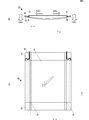
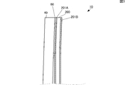
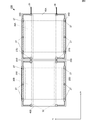
図1は、本発明の振動装置の一例を示すキー入力装置10の外観斜視図である。図2(A)は、キー入力装置10の正面図であり、図2(B)は、側面図である。図3は、キー入力装置10の部分拡大図である。図4は、キー入力装置10の主要構成を示すブロック図である。
キー入力装置10は、図1に示すように、圧電フィルム30、振動板40、スペーサ70、引出配線20、および接着テープ25を備えている。また、図4に示すように、キー入力装置10は、ハードウェア構成として、タッチ検出部80と、タッチ検出部80に接続される制御部90と、制御部90に接続される駆動部81と、駆動部81に接続される圧電フィルム30と、を備えている。キー入力装置10は、いわゆるキーボードであり、不図示のホスト装置(パーソナルコンピュータ等の情報処理装置)に無線または有線で接続され、ユーザのキー入力を受け付けるインタフェースである。
平板状の振動板40には、不図示のタッチ検出部80が設けられている。タッチ検出部80は、例えば各キー配列に対応した位置に設けられ、利用者のタッチ操作を検出する。なお、タッチ検出部80は、ユーザのタッチ操作を検出する機能であればどの様な方式であってもよく、メンブレン式、静電容量式、または圧電フィルム式等の様々な方式を用いることができる。
ユーザがタッチ検出部80をタッチすると、駆動部81は、圧電フィルム30に駆動信号を印加する。これにより圧電フィルム30が伸縮する。
圧電フィルム30は、振動板40の背面において、振動板40の短手方向(Y方向)の両端に固定されている。振動板40は、例えばアクリル樹脂PMMAで構成されている。なお、振動板40は、金属板、PET、ポリカーボネイト(PC)、繊維強化プラスチック(FRP)、ガラス等の他の材料を用いてもよい。なお、本実施形態では、圧電フィルム30は、Y方向の両端に固定されているが、例えば長手方向(X方向)の両端に固定する態様でもよい。
図3に示すように、圧電フィルム30は、平面視して矩形状のベースフィルム200と、該ベースフィルム200の対向する両主面に形成された電極201Aおよび電極201Bを備える。
ベースフィルム200は、圧電性樹脂であり、例えばポリフッ化ビニリデン(PVDF)、またはキラル高分子等の材料を用いる。より好ましくは、PVDFであるが、透光性の高いポリ乳酸(PLA:Poly Lactic Acid)であってもよい。PLAを用いる場合、他の構成も透光性の高い材料を用いることにより、正面視した略全面が高い透光性を有するキー入力装置10を実現することができる。ベースフィルムおよび電極を透明にすることで、完成品の状態で不良品を見つけることが容易になる。また、キーボードを内側から光らせる等、デザイン性の向上を図ることができる。
また、PLAは、焦電性が無いため、周囲温度の変化に影響されないため、気温の変化、電子機器の発熱、指が接触することによる温度変化等によって振動の強さが変わらない。
ベースフィルム200は、PLAで構成される場合、図2(A)に示すように、延伸方向に対して各外周辺が略45°となるように裁断することで、矩形状を形成して、圧電性を持たせる。
電極201Aおよび電極201Bは、ベースフィルム200の両主面の略全面に形成されている。電極201Aおよび電極201Bは、酸化インジウムスズ(ITO)、酸化亜鉛(ZnO)、ポリチオフェンを主成分とすることが好ましい。また、アルミ蒸着電極または銅はく電極等、導電率の高い材料を電極にして、省電力化を図ることもできる。
なお、電極201Aおよび電極201Bには、銀ナノワイヤ電極を用いることも可能であるし、透光性が低くてよい使用態様であれば、アルミ蒸着電極を用いることが好ましい。電極201Aおよび電極201Bには、引出配線20が接続され、駆動信号が印加されるようになっている。振動板40側に配置される電極201Aは、接着層60を介して振動板40に貼り付けられる。
図1および図2(B)に示すように、振動板40は、圧電フィルム30の存在する側(振動板40の背面側)に対して反対側(振動板40の正面側)に湾曲して突出する形状となるように、圧電フィルム30へ固定されている。なお、正面側に突出する形状は、本発明において必須の構成要素ではない。振動板40は、圧電フィルム30が接続された後の状態で背面側に突出する形状でなければよく、完全に平坦な状態であってもよい。また、仮に圧電フィルム30が接続される前の状態で、振動板40が背面側に湾曲していた場合でも、スペーサ70により正面側に突出する形状とすることができる。
ただし、本実施形態において、振動板40の湾曲状態は、説明のために誇張して記載しており、実際には、振動板40の主面と圧電フィルム30の主面は、より平行に近く、外観上はほぼ平坦となる。
このように、振動板40は、平板面が湾曲した状態で圧電フィルム30に固定されるため、図2(B)の白抜き矢印F901のように、曲げ応力が加わった状態で圧電フィルム30に固定される。また、圧電フィルム30には、図2(B)の白抜き矢印S901に示すように、圧電フィルム30の主面における短手方向に引張力が係った状態となる。
駆動部81が、圧電フィルム30に駆動信号を印加し、圧電フィルム30がY方向に沿って収縮すると、振動板40は、圧電フィルム30に固定されている箇所(短手方向の端部)から中央方向に引っ張られる。これにより、振動板40のY方向の中心部分は、前方へより突出するように湾曲する。また、振動板40のY方向の端部は、背面側に移動する。図2(A)に示す1点破線の部分は、振動の節となる箇所であり、本発明の第1領域に相当する。振動板40は、第1領域では、圧電フィルム30が伸縮しても、ほぼ振動することがなく、正面側にも背面側にもほぼ移動しない。
一方、駆動部81が、圧電フィルム30に逆相の駆動信号を印加し、圧電フィルムがY方向に沿って伸張すると、振動板40は、中央方向から圧電フィルム30に固定されている箇所(短手方向の端部)に引っ張られる。これにより、振動板40のY方向の中心部分は、前方への突出量が低下した湾曲状態となる。また、振動板40のY方向の端部は、正面側に移動する。
したがって、振動板40は、駆動信号の振幅に応じて、第1領域以外の箇所(第2領域)では、正面方向および背面方向(Z方向)に沿って振動する。これにより、駆動信号に応じた振動が振動板40を介してユーザに伝達される。したがって、ユーザは、タッチ検出部80を介して振動板40をタッチすると、振動がフィードバックされるため、キーを「押した」と感じることができる。
そして、振動板40には、非動作状態で定常的な曲げ応力が与えられているため、圧電フィルム30の伸張時に振動板40に与えられる力は、当該曲げ応力と同じ方向となる。したがって、キー入力装置10は、振動板40を効率的に振動させることができ、圧電フィルムを用いた場合であってもある程度強い振動を伝えることができる。また、モータ等による振動に比べると、キー入力装置10を薄くすることができるとともに、モータよりも応答性が高いため、タッチの感触を精度よく再現することができる。
上述したように、振動板40は、図2(A)に示す1点破線の付近において、振動しない第1領域が存在する。本実施形態では、スペーサ70は、この第1領域に配置されている。
スペーサ70は、振動板40を支持する機能と、圧電フィルム30を振動板40から離すことで引張力を生じさせる機能と、を有する。スペーサ70は、第1領域に配置されることで、振動板40の振動を阻害せず、かつ圧電フィルム30の伸縮を阻害しないようになっている。ただし、スペーサ70は、本発明において必須の構成ではない。
引出配線20は、Y方向の端部において、グロメット、導通テープ、熱溶着導電シートまたは導電ペースト等で電極201Aまたは電極201Bに電気的に接続される。圧電フィルム30のY方向の端部は、振動板40に接続され、かつY方向の端部は、圧電フィルム30が伸縮しない箇所である。よって、圧電フィルム30の伸縮により引出配線20と圧電フィルム30との接続箇所に接触不良が生じる可能性が低下する。また、引出配線20により電極が引っ張られることもないため、電極が剥離したり、圧電フィルムが破損したりするおそれも低下する。
ただし、圧電フィルム30のY方向の端部においても、振動板40が振動する箇所(第2領域)となるため、振動板40の振動により引出配線20と圧電フィルム30との接続箇所に接触不良が生じる可能性もある。そこで、引出配線20は、圧電フィルム30のY方向の端部から、第1領域に向かって引き出され、スペーサ70の近傍位置から外部に引き出される。したがって、引出配線20は、Y方向の端部よりも振動板40の振動が少ない部分から外部に引き出されることになる。
また、引出配線20は、スペーサ70の近傍で、接着テープ25により振動板40に貼り付けられて固定されている。引出配線20は、圧電フィルム30との接続箇所から接着テープ25で貼り付けられる箇所まで、撓んだ状態となっている。したがって、振動板40の振動が引出配線20を介して外部に伝達されることもないし、引出配線20が引っ張られることもない。
なお、引出配線20は、スペーサ70の近傍から外部に引き出される態様となっているが、スペーサ70がない場合には、最も振動が小さい位置(第1領域)から外部に引き出される態様とすることが好ましい。また、この例では、引出配線20は、接着テープ25で振動板40に貼り付けられる態様であったが、例えばはんだにより振動板40に固定される態様であってもよい。また、振動板40に引出配線20を固定する構造を設けてもよい。また、固定箇所は、振動板40に限らず、第1領域に配置されているスペーサに固定される態様であってもよい。
また、この例では、引出配線20は、Y方向の端部で圧電フィルム30に接続される態様を示したが、他の位置で圧電フィルム30に接続される態様であってもよい。他の位置で圧電フィルム30に接続される場合であっても、引出配線20は、振動の小さい第1領域に向かって引き出されることで、フィルムの伸縮による接続不良等の発生を抑制する効果が生じる。
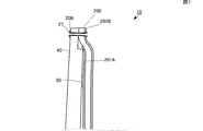
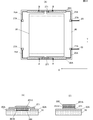
また、例えば、図9(A)の平面図、図9(B)および図9(C)の断面図に示すように、引出配線20は、第1領域で圧電フィルム30に接続され、そのまま第1領域から外部に引き出されるようになっていてもよい。この場合、図9(C)の断面図に示すように、引出配線20は、例えば、圧電フィルム30との接続位置から正面方向(Z方向)に向かって引き出され、振動板40にテープ25で貼り付けられる。引出配線20は、圧電フィルム30との接続位置から振動板40まで撓んだ状態となっている。したがって、圧電フィルム30の伸縮を阻害せず、かつ振動板40の振動が引出配線20を介して外部に伝達されることもないし、引出配線20が引っ張られることもない。
次に、図5(A)は、引出配線の変形例に係る平面図である。上述の例では、引出配線20は、リード線の態様であったが、この例における引出配線は、振動板40の正面に形成された電極パターンからなる。振動板40の正面のうち、Y方向の端部には、X方向に沿って長方形状の電極パターン20Aが設けられている。
電極パターン20Aおよび振動板40には、孔が開けられ、当該孔にはグロメット27が挿入されている。グロメット27は、振動板40の背面側で圧電フィルム30の電極201Aまたは201Bと電気的に接続される。図5(B)は、グロメット27を介して電極パターン20Aおよび電極201Aが接続される場合の断面図である。この箇所では、電極201Bは、電極パターン20Aに接触しないように、エッチング等により除去されている。図5(C)は、グロメット27を介して電極パターン20および電極201Bが接続される場合の断面図である。この箇所では、電極201Aは、電極パターン20Aに接触しないように、エッチング等により除去されている。
電極パターン20Aは、Y方向の端部からスペーサ70が配置されている位置(すなわち第1領域)に向かって形成された電極パターン25Aを介して、リード線である引出配線20を接続する部分(電極接続部27A)に電気的に接続される。電極接続部27Aには、引出配線20がはんだ等で接続され、外部に引き出される。引出配線20は、振動板40の正面側で接続されていてもよいが、電極接続部27Aにスルーホールやグロメット等を形成することにより、背面側で接続することも可能である。また、この場合、振動板40の背面側を薄く削ることにより、引出配線20およびグロメット等の出っ張りが背面側へ突出することを防止することもできる。
また、各電極パターンは、振動板40の背面に形成されていてもよい。電極パターンを背面に形成する場合も、引出配線20は、振動板40の背面側で接続されていてもよいが、電極接続部27Aにスルーホールやグロメット等を形成することにより、正面側で接続することも可能である。また、振動板40の正面側を薄く削ることにより、引出配線20およびグロメット等の出っ張りが正面側へ突出することを防止することもできる。
なお、図5の例では、X方向の両端部に電極接続部27Aが設けられているが、いずれか一方の電極接続部27Aだけ設ける態様であってもよい。
図5に示す振動装置は、以上の構成により、リード線を引き回す必要がなくなる。また、電極接続部27Aと引出配線20は、はんだ等で強固に接続される。また、引出配線20が仮に外れた場合にも容易に修復することができる。
次に、図6(A)は、引出配線の変形例(図5の応用例)に係る平面図であり、図6(B)は背面図である。図5の例では、電極パターンは、全て振動板40の正面側(または背面側)に形成されていたが、この例では、電極パターン20Bは、振動板40のY方向の端部の正面側にだけ形成されている。ただし、電極パターン20Bは、X方向の端部において、スルーホール等を介して裏面側の電極パターン20Cに接続される。そして、Y方向の端部からスペーサ70が配置されている位置(すなわち第1領域)に向かって形成された電極パターン25Cを介して、引出配線20を接続する部分(電極接続部27C)に電気的に接続される。
この態様では、正面側には、Y方向の端部だけに電極パターンが形成され、残りの電極パターンは、背面側に形成されている。したがって、振動板40のY方向の端部以外は、電極パターンやリード線がなくなり、振動板40の正面を平坦に保つことができる。
また、図7に示すように、電極パターン20Bの背面側は、振動板40を薄く削ることにより、グロメット27により厚くなった箇所を収納することができ、振動板40の厚みを薄くすることが可能となる。なお、図7では、グロメット27と電極201Bが直接触れるように配置されているが、別体の導電性シートを間に介してもよい。導電性シートを付加することによって、グロメット27の取り付け時または振動時等において、圧電フィルムや電極201Bにかかる負荷を軽減することができる。なお、導電性シートを付加する場合であっても、図7に示すように振動板40を薄く削り、溝を形成していることによって、振動板40の厚みが大きく増えることはない。
次に、図8は、複数の圧電フィルムを備えるキー入力装置10Aの正面図である。キー入力装置10Aは、1枚の振動板が第1の振動部40Aと第2の振動部40Bとに分かれている。第1の振動部40Aと第2の振動部40Bとは、振動の節となる第1領域の近傍で接続されている。すなわち、振動板のX方向の中心部分は、第2領域が削られ、第1領域が残された状態となっている。これにより、第1の振動部40Aと第2の振動部40Bとは、振動が少ない箇所で接続されることになり、振動により接続箇所が壊れるおそれはない。
キー入力装置10Aは、2つの圧電フィルム30Aおよび圧電フィルム30Bを備えている。圧電フィルム30Aは、第1の振動部40AのY方向の端部で接続され、圧電フィルム30Bは、第2の振動部40BのY方向の端部で接続されている。第1の振動部40Aおよび第2の振動部40Bは、それぞれ圧電フィルム30Aおよび圧電フィルム30Bの伸縮により振動する。
仮に、振動部が分割されていない場合において、圧電フィルム一方の圧電フィルムの引張力が強い場合、他方の圧電フィルムの引張力が弱くなってしまうため、引張力が弱い側の圧電フィルムの伸縮が振動板40に伝わり難い状態となる。しかし、図8に示す例のように、1枚の振動板が2つの振動部に分かれて、それぞれに圧電フィルムが接続されている場合、それぞれの圧電フィルムにおいて引張力を一定に保つことができ、各圧電フィルムの伸縮により、適切に振動板を振動させることができる。
また、キー入力装置10Aは、図5に示した例と同様に、振動板40の正面に電極パターン20Dが形成されている。ただし、圧電フィルム30Aおよび圧電フィルム30Bにそれぞれの接続される電極パターン20Dは、Y方向の端部からスペーサ70が配置されている位置(すなわち第1領域)に向かって形成された電極パターン25Dと、スペーサ70の近傍に設けられ、X方向に沿って形成された電極パターン27Dと、を介して電気的に接続される。電極パターン27Dは、振動板の節となる第1領域に配置され、第1の振動部40Aと第2の振動部40Bとを接続する箇所に配置されている。
これにより、振動により第1の振動部40Aと第2の振動部40Bとの接続箇所が壊れるおそれはなく、かつ2つの圧電フィルムを電気的に接続する引出配線も、振動により接続不良となるおそれもない。
図8では、第1の振動部40Aと第2の振動部40Bとは、第1領域で接続されているが、第1の振動部40Aと第2の振動部40Bとは別の振動板として、電極パターン27Dの部分をリード線とする態様であってもよい。この場合、第1の振動部40Aと第2の振動部40Bとが重なるように折りたたむことができる。折りたたむことで、面積を小さくして持ち運ぶことができる。また、振動板の厚みは極めて薄くなっているため、折りたたんだ場合でも持ち運びに不便となることはない。
なお、圧電フィルムは、電圧を加えることで面方向に変形するフィルムの一例であるが、他にも電圧を加えることで面方向に変形するフィルムは、例えば電歪フィルム、エレクトレットフィルム、コンポジットフィルム、または電気活性高分子フィルム等がある。
また、「電圧を加えることで面方向に変形するフィルム」は、例えば圧電セラミックスおよび樹脂フィルムを用いることでも実現することができる。例えば、複数の樹脂フィルムを、圧電セラミックスを介して接続し、これら複数の樹脂フィルムをそれぞれ振動板40に接続することで実現することができる。
さらに、「電圧を加えることで面方向に変形するフィルム」は、単層でも良いし、積層しても良い。特に積層する枚数を増やすことによってより強い振動を得ることが出来る。
なお、上述の例では、振動装置の一例として触覚提示装置を示したが、本発明の振動装置は、必ずしも「触覚」に限るものではなく、例えばスピーカ等の音を出力する装置も、振動装置の一例となる。
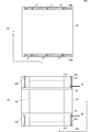
図10(A)は、振動板40と圧電フィルム30との接続に熱溶着導電シートを用いる場合の平面図(振動板40の裏面図)である。図10(B)は、図10(A)に示すA-A断面図であり、図10(C)は、図10(A)に示すB-B断面図である。
この例では、圧電フィルム30は、Y方向の端部のうち、一部だけが引き出されていて、電極パターン20Aに接続されている(ただし、圧電フィルム30の一部だけが引き出されていることは本発明に必須の構成ではない)。
圧電フィルム30は、熱溶着導電シート271に貼り付けられ、該熱溶着導電シート71を介して電極パターン20Aに電気的に接続される。図10(B)に示すように、圧電フィルム30のうち電極201Aが接続される箇所では、電極パターン20Aが形成されていないため、電極201Aと電極パターン20Aが接触することはない。ただし、電極パターン20Aと圧電フィルム30との隙間には、熱溶着導電シート271が入り込む可能性があるため、当該隙間には、絶縁材が配置されることが好ましい。一方、図10(C)に示すように、圧電フィルム30のうち電極201Bが接続される箇所では、電極パターン20Aに熱溶着導電シート271の第1主面が貼り付けられ、当該熱溶着導電シート271の第2主面に圧電フィルム30の電極201Bが貼り付けられる。図10(C)の場合には、電極201Aと電極パターン20Aとが接触する可能性は低いため、絶縁体等を配置する必要はない。
このように、熱溶着導電シートを介して圧電フィルム30と電極パターン20Aとを接続することで、グロメット27に比較すると、厚みが低減される。また、異種金属が存在しないため、電食が起きない。さらに、図5(B)および図5(C)のような電極のエッチングが不要である。さらに、導電シートは、接着が容易であり、かつ熱溶着導電シートの場合は周囲温度の影響を受けにくい。一方で、グロメットは、熱溶着導電シートよりも強固に固定することができ、かつ、固定状態を視認することができる。
10,10A…キー入力装置
20…引出配線
20A,20B,20C,20D…電極パターン
25…接着テープ
25A,25C,25D…電極パターン
27…グロメット
27A,27C…電極接続部
27D…電極パターン
30,30A,30B…圧電フィルム
40…振動板
40A…第1の振動部
40B…第2の振動部
60…接着層
70…スペーサ
80…タッチ検出部
81…駆動部
90…制御部
200…ベースフィルム
201A,201B…電極
20…引出配線
20A,20B,20C,20D…電極パターン
25…接着テープ
25A,25C,25D…電極パターン
27…グロメット
27A,27C…電極接続部
27D…電極パターン
30,30A,30B…圧電フィルム
40…振動板
40A…第1の振動部
40B…第2の振動部
60…接着層
70…スペーサ
80…タッチ検出部
81…駆動部
90…制御部
200…ベースフィルム
201A,201B…電極
Claims (8)
- 振動板と、
電圧を加えることで面方向に伸縮し、両主面に電極が設けられたフィルムと、
前記電極から外部に引き出される引出配線と、
を備え、
前記振動板は、振動の節に位置する第1領域と、
振動の節以外に位置する第2領域と、を有し、
前記引出配線は、前記第2領域から前記第1領域に向けて引き出される箇所を有することを特徴とする振動装置。 - 前記フィルムは、複数に分割されていて、
各フィルムの電極同士を接続するための接続用配線は、前記第2領域から前記第1領域に向けて引き出される箇所を有することを特徴とする請求項1に記載の振動装置。 - 前記引出配線は、前記振動板に形成された電極パターンからなる請求項1または請求項2に記載の振動装置。
- 前記電極と前記引出配線は、前記フィルムと前記振動板との接続箇所よりも、当該フィルムの端部側で接続される請求項1乃至請求項3のいずれかに記載の振動装置。
- 前記振動板が第1の振動部と第2の振動部とに分かれていて、
前記引出配線は、前記第1の振動部および前記第2の振動部が連結される部分に配置されている請求項1乃至請求項4のいずれかに記載の振動装置。 - 振動板と、
電圧を加えることで面方向に伸縮し、両主面に電極が設けられたフィルムと、
前記電極から外部に引き出される引出配線と、
を備え、
前記振動板は、振動の節に位置する第1領域と、
振動の節以外に位置する第2領域と、を有し、
前記引出配線は、前記第1領域から外部に引き出されることを特徴とする振動装置。 - 前記フィルムは、圧電フィルムである請求項1乃至請求項6のいずれかに記載の振動装置。
- 請求項1乃至請求項7のいずれかに記載の振動装置と、
タッチ操作を検出するタッチ検出部と、
タッチ検出部がタッチ操作を検出したときに、前記フィルムに駆動信号を印加する駆動部と、
を備えた触覚提示装置。
Priority Applications (2)
| Application Number | Priority Date | Filing Date | Title |
|---|---|---|---|
| JP2017543604A JP6414644B2 (ja) | 2015-10-02 | 2016-09-30 | 振動装置および触覚提示装置 |
| US15/890,425 US10381545B2 (en) | 2015-10-02 | 2018-02-07 | Vibration device and tactile presentation device |
Applications Claiming Priority (2)
| Application Number | Priority Date | Filing Date | Title |
|---|---|---|---|
| JP2015196612 | 2015-10-02 | ||
| JP2015-196612 | 2015-10-02 |
Related Child Applications (1)
| Application Number | Title | Priority Date | Filing Date |
|---|---|---|---|
| US15/890,425 Continuation US10381545B2 (en) | 2015-10-02 | 2018-02-07 | Vibration device and tactile presentation device |
Publications (1)
| Publication Number | Publication Date |
|---|---|
| WO2017057656A1 true WO2017057656A1 (ja) | 2017-04-06 |
Family
ID=58423711
Family Applications (1)
| Application Number | Title | Priority Date | Filing Date |
|---|---|---|---|
| PCT/JP2016/078969 Ceased WO2017057656A1 (ja) | 2015-10-02 | 2016-09-30 | 振動装置および触覚提示装置 |
Country Status (3)
| Country | Link |
|---|---|
| US (1) | US10381545B2 (ja) |
| JP (1) | JP6414644B2 (ja) |
| WO (1) | WO2017057656A1 (ja) |
Cited By (1)
| Publication number | Priority date | Publication date | Assignee | Title |
|---|---|---|---|---|
| JPWO2021079837A1 (ja) * | 2019-10-23 | 2021-04-29 |
Citations (3)
| Publication number | Priority date | Publication date | Assignee | Title |
|---|---|---|---|---|
| JP2009154111A (ja) * | 2007-12-27 | 2009-07-16 | Sony Corp | 圧電ポンプ、冷却装置及び電子機器 |
| WO2012157691A1 (ja) * | 2011-05-17 | 2012-11-22 | 株式会社村田製作所 | 平面型スピーカおよびav機器 |
| WO2015053247A1 (ja) * | 2013-10-08 | 2015-04-16 | 株式会社村田製作所 | 触覚提示装置 |
Family Cites Families (5)
| Publication number | Priority date | Publication date | Assignee | Title |
|---|---|---|---|---|
| JPH10135531A (ja) * | 1996-10-30 | 1998-05-22 | Taiyo Yuden Co Ltd | 圧電トランス |
| JPH10256618A (ja) * | 1997-03-10 | 1998-09-25 | Alps Electric Co Ltd | 圧電振動装置 |
| JP4222160B2 (ja) * | 2002-10-30 | 2009-02-12 | ソニー株式会社 | 入力装置およびその製造方法 |
| JP4355017B1 (ja) * | 2008-05-14 | 2009-10-28 | 敬三 森川 | 情報送信装置及び情報送受信装置 |
| JP6361833B2 (ja) * | 2015-09-30 | 2018-07-25 | 株式会社村田製作所 | 振動装置および触覚提示装置 |
-
2016
- 2016-09-30 WO PCT/JP2016/078969 patent/WO2017057656A1/ja not_active Ceased
- 2016-09-30 JP JP2017543604A patent/JP6414644B2/ja active Active
-
2018
- 2018-02-07 US US15/890,425 patent/US10381545B2/en active Active
Patent Citations (3)
| Publication number | Priority date | Publication date | Assignee | Title |
|---|---|---|---|---|
| JP2009154111A (ja) * | 2007-12-27 | 2009-07-16 | Sony Corp | 圧電ポンプ、冷却装置及び電子機器 |
| WO2012157691A1 (ja) * | 2011-05-17 | 2012-11-22 | 株式会社村田製作所 | 平面型スピーカおよびav機器 |
| WO2015053247A1 (ja) * | 2013-10-08 | 2015-04-16 | 株式会社村田製作所 | 触覚提示装置 |
Cited By (3)
| Publication number | Priority date | Publication date | Assignee | Title |
|---|---|---|---|---|
| JPWO2021079837A1 (ja) * | 2019-10-23 | 2021-04-29 | ||
| WO2021079837A1 (ja) * | 2019-10-23 | 2021-04-29 | 株式会社村田製作所 | 面方向型振動構造 |
| JP7243850B2 (ja) | 2019-10-23 | 2023-03-22 | 株式会社村田製作所 | 面方向型振動構造及び触覚提示装置 |
Also Published As
| Publication number | Publication date |
|---|---|
| US20180175279A1 (en) | 2018-06-21 |
| US10381545B2 (en) | 2019-08-13 |
| JP6414644B2 (ja) | 2018-10-31 |
| JPWO2017057656A1 (ja) | 2018-08-02 |
Similar Documents
| Publication | Publication Date | Title |
|---|---|---|
| JP6037039B2 (ja) | 触覚提示装置 | |
| JP6103141B2 (ja) | 振動装置 | |
| JP3871991B2 (ja) | タッチパネル | |
| JP6079893B2 (ja) | ヘッドフォン | |
| WO2016027668A1 (ja) | 触覚提示装置 | |
| CN103282865B (zh) | 压电振动装置和触摸面板装置 | |
| US20170173634A1 (en) | Stretchable film laminate and electronic device | |
| KR101663089B1 (ko) | 압전 소자 및 압전 스피커 | |
| JP6176409B2 (ja) | 振動装置および触覚提示装置 | |
| JP5975185B2 (ja) | 触覚提示装置 | |
| JP7429506B2 (ja) | 振動パネル及び電子機器 | |
| JP6414644B2 (ja) | 振動装置および触覚提示装置 | |
| JP6065158B2 (ja) | 触覚提示装置 | |
| JP6318970B2 (ja) | 振動体および触覚提示装置 | |
| JP2015075856A (ja) | 触覚提示装置 | |
| JP7679344B2 (ja) | 振動装置およびこれを含む装置 | |
| JP6590082B2 (ja) | 振動装置 | |
| JP6428076B2 (ja) | 触覚提示装置 |
Legal Events
| Date | Code | Title | Description |
|---|---|---|---|
| 121 | Ep: the epo has been informed by wipo that ep was designated in this application |
Ref document number: 16851825 Country of ref document: EP Kind code of ref document: A1 |
|
| ENP | Entry into the national phase |
Ref document number: 2017543604 Country of ref document: JP Kind code of ref document: A |
|
| NENP | Non-entry into the national phase |
Ref country code: DE |
|
| 122 | Ep: pct application non-entry in european phase |
Ref document number: 16851825 Country of ref document: EP Kind code of ref document: A1 |