WO2017056812A1 - 把持装置 - Google Patents
把持装置 Download PDFInfo
- Publication number
- WO2017056812A1 WO2017056812A1 PCT/JP2016/075072 JP2016075072W WO2017056812A1 WO 2017056812 A1 WO2017056812 A1 WO 2017056812A1 JP 2016075072 W JP2016075072 W JP 2016075072W WO 2017056812 A1 WO2017056812 A1 WO 2017056812A1
- Authority
- WO
- WIPO (PCT)
- Prior art keywords
- gripping
- portions
- pair
- gripped
- fixed
- Prior art date
- Legal status (The legal status is an assumption and is not a legal conclusion. Google has not performed a legal analysis and makes no representation as to the accuracy of the status listed.)
- Ceased
Links
Images




Classifications
-
- B—PERFORMING OPERATIONS; TRANSPORTING
- B23—MACHINE TOOLS; METAL-WORKING NOT OTHERWISE PROVIDED FOR
- B23P—METAL-WORKING NOT OTHERWISE PROVIDED FOR; COMBINED OPERATIONS; UNIVERSAL MACHINE TOOLS
- B23P19/00—Machines for simply fitting together or separating metal parts or objects, or metal and non-metal parts, whether or not involving some deformation; Tools or devices therefor so far as not provided for in other classes
- B23P19/02—Machines for simply fitting together or separating metal parts or objects, or metal and non-metal parts, whether or not involving some deformation; Tools or devices therefor so far as not provided for in other classes for connecting objects by press fit or for detaching same
-
- B—PERFORMING OPERATIONS; TRANSPORTING
- B23—MACHINE TOOLS; METAL-WORKING NOT OTHERWISE PROVIDED FOR
- B23P—METAL-WORKING NOT OTHERWISE PROVIDED FOR; COMBINED OPERATIONS; UNIVERSAL MACHINE TOOLS
- B23P19/00—Machines for simply fitting together or separating metal parts or objects, or metal and non-metal parts, whether or not involving some deformation; Tools or devices therefor so far as not provided for in other classes
- B23P19/04—Machines for simply fitting together or separating metal parts or objects, or metal and non-metal parts, whether or not involving some deformation; Tools or devices therefor so far as not provided for in other classes for assembling or disassembling parts
-
- B—PERFORMING OPERATIONS; TRANSPORTING
- B23—MACHINE TOOLS; METAL-WORKING NOT OTHERWISE PROVIDED FOR
- B23Q—DETAILS, COMPONENTS, OR ACCESSORIES FOR MACHINE TOOLS, e.g. ARRANGEMENTS FOR COPYING OR CONTROLLING; MACHINE TOOLS IN GENERAL CHARACTERISED BY THE CONSTRUCTION OF PARTICULAR DETAILS OR COMPONENTS; COMBINATIONS OR ASSOCIATIONS OF METAL-WORKING MACHINES, NOT DIRECTED TO A PARTICULAR RESULT
- B23Q3/00—Devices holding, supporting, or positioning work or tools, of a kind normally removable from the machine
- B23Q3/02—Devices holding, supporting, or positioning work or tools, of a kind normally removable from the machine for mounting on a work-table, tool-slide, or analogous part
- B23Q3/06—Work-clamping means
-
- B—PERFORMING OPERATIONS; TRANSPORTING
- B23—MACHINE TOOLS; METAL-WORKING NOT OTHERWISE PROVIDED FOR
- B23Q—DETAILS, COMPONENTS, OR ACCESSORIES FOR MACHINE TOOLS, e.g. ARRANGEMENTS FOR COPYING OR CONTROLLING; MACHINE TOOLS IN GENERAL CHARACTERISED BY THE CONSTRUCTION OF PARTICULAR DETAILS OR COMPONENTS; COMBINATIONS OR ASSOCIATIONS OF METAL-WORKING MACHINES, NOT DIRECTED TO A PARTICULAR RESULT
- B23Q7/00—Arrangements for handling work specially combined with or arranged in, or specially adapted for use in connection with, machine tools, e.g. for conveying, loading, positioning, discharging, sorting
- B23Q7/04—Arrangements for handling work specially combined with or arranged in, or specially adapted for use in connection with, machine tools, e.g. for conveying, loading, positioning, discharging, sorting by means of grippers
-
- B—PERFORMING OPERATIONS; TRANSPORTING
- B25—HAND TOOLS; PORTABLE POWER-DRIVEN TOOLS; MANIPULATORS
- B25B—TOOLS OR BENCH DEVICES NOT OTHERWISE PROVIDED FOR, FOR FASTENING, CONNECTING, DISENGAGING, OR HOLDING
- B25B5/00—Clamps
- B25B5/14—Clamps for work of special profile
-
- B—PERFORMING OPERATIONS; TRANSPORTING
- B25—HAND TOOLS; PORTABLE POWER-DRIVEN TOOLS; MANIPULATORS
- B25J—MANIPULATORS; CHAMBERS PROVIDED WITH MANIPULATION DEVICES
- B25J15/00—Gripping heads and other end effectors
- B25J15/08—Gripping heads and other end effectors having finger members
Definitions
- the present invention relates to a gripping device.
- Patent Document 1 discloses a gripping jig that can grip a plurality of types of gripped members having different diameters.
- the gripping jig includes two gripping members for gripping the gripped member, an elastic member for biasing the two gripping members, and an operation shaft for sliding the two gripping members.
- This gripping jig is configured to operate the operating shaft so as to separate the two gripping members, and by inserting the gap between the two gripping members, members to be gripped of various diameters are inserted between them. It is a possible configuration.
- the member to be grasped is inserted in a state where the two grasping members are separated from each other, and then the operation on the operation shaft is released, the two grasping members are pressed in the direction in which the two grasping members approach each other by the elastic force.
- the member to be gripped is stably held.
- Patent Document 1 since the gripping tool of Patent Document 1 is intended to grip only one shaft member, it cannot be applied to an object to be gripped of two or more parts, and is unique to such an object. Can't handle the problem. For example, as an object to be grasped, an object W having three protrusions S1, S2, S3 as shown in FIGS. 11A and 11B is also assumed. It may be desirable to sandwich and grip S3. However, the gripping jig of Patent Document 1 cannot meet such a requirement.
- FIG. 11C As a device that can hold the object W as shown in FIGS. 11A and 11B and hold the three projecting portions S1, S2, and S3, a holding device as shown in FIG. M is mentioned.
- the gripping device M in FIG. 11C is configured to allow the pair of gripping members C1 and C2 to approach and separate from each other.
- a two-dot chain line shown in FIG. When gripping the object W, a two-dot chain line shown in FIG.
- the pair of gripping members C1 and C2 are brought close to each other.
- the pair of gripping members C1 and C2 sandwich the three protrusions S1, S2, and S3 by the recesses D1 and D2, and grip the object W in a suspended manner, for example.
- the pair of gripping members C1 and C2 are formed by the recesses D1 and D2 into the three projecting portions S1, S2, and S2. S3 can be pinched and held securely.
- the arrangement of the recesses D1 and D2 formed in the pair of gripping members C1 and C2 is completely in the normal positional relationship of the three protrusions S1, S2, and S3. Combined fixed arrangement. For this reason, when a position shift occurs in any of the three protrusions S1, S2, and S3, the recesses formed in the gripping members C1 and C2 cannot normally sandwich the position shift protrusions. There is a risk that the object W will be suspended in an unstable gripping state.
- the present invention has been made in view of the above-described situation, and the object can be gripped by sandwiching at least three projecting portions provided on the object, and the projecting portion is misaligned.
- the gripping device of the present invention is formed in a positional relationship in which a plurality of parts and three or more projecting portions project on one side are targets for gripping, and the plurality of pressing portions are fixed to each other.
- the holding member has a fixed holding part provided in pairs.
- the fixed gripping part has a pair of gripping members approaching each other, and a plurality of pressing parts formed on one gripping member and a plurality of pressing parts formed on the other gripping member, at least two protrusions of the object Are sandwiched respectively.
- the gripping device further includes a pair of support portions configured to approach each other in conjunction with the approaching operation of the pair of gripping members and to sandwich another protrusion different from the protrusion sandwiched by the fixed gripping portion. Has a grip.
- At least one of the support portions has a configuration in which a change in position is allowed with respect to the plurality of pressing portions formed on the interlocking gripping member, and the elastic member is inserted when the other protrusion is sandwiched between the pair of support portions. The elastic force is applied and the other protrusions are continuously pushed.
- the fixed gripping portion of the gripping device brings a pair of gripping members close to each other, and includes at least two objects of the object by a plurality of pressing portions formed on one gripping member and a plurality of pressing portions formed on the other gripping member.
- Each of the two protrusions can be sandwiched.
- the movable gripper can move the pair of support parts closer in conjunction with the approaching action of the pair of gripping members in the fixed gripper, and can sandwich another protrusion that is different from the protrusion sandwiched by the fixed gripper. That is, any of the at least three protrusions formed on the object can be gripped by the fixed gripper and the movable gripper.
- At least one of the support portions provided in the movable gripping portion is allowed to change its position with respect to the plurality of pressing portions formed on the interlocking gripping member, and is elastic when the “other protruding portion” is sandwiched. The elastic force of the member is applied, and the “other protrusion” is continuously pushed. Because of such a configuration, even if the position of the “other protrusion” sandwiched by the movable gripper is slightly shifted from the projecting part sandwiched by the fixed gripper, the position of the support unit that is allowed to change its position is shifted. Accordingly, the other protrusions are continuously pushed at the position after the displacement.
- the movable gripper can automatically adjust the position of the support portion in accordance with the positional deviation of the “other protrusion”, and pushes the “other protrusion” to the support portion even after the adjustment. Therefore, the “other protrusion” can be gripped with a sufficient gripping force.
- the gripping device can grip the object in such a manner as to sandwich at least three protrusions provided on the object, and suppresses the influence of the position shift even when the position shift occurs in the protrusion.
- the protruding portion can be securely gripped.
- the object to be gripped by the gripping device of the present invention may be provided with protrusions gripped by the fixed gripping part on both sides of the other protrusions gripped by the movable gripping part.
- the holding part formed in one holding member is arranged on both sides of one supporting part in a pair of supporting parts, and the holding part formed in the other holding member is arranged on both sides of the other supporting part. Also good.
- the fixed gripping portion operates so as to sandwich the protruding portions on both sides among the three or more protruding portions configured on the object.
- the movable gripping part grips the intermediate projecting part (the other projecting part) while causing the position adjusting action and the biasing action at the support part that is allowed to change its position. That is, this gripping device has an advantageous configuration in the case of gripping an object having three or more projecting portions and the intermediate projecting portions being easily displaced with respect to the projecting portions on both sides.
- the three or more protrusions provided can be more securely sandwiched and stably held.
- the plurality of pressing portions of the fixed grip portion are disposed on both sides, gripping can be further stabilized.
- any one of the pair of support portions may be formed in a form in which the positional relationship with the plurality of pressing portions is fixed in any one member of the pair of gripping members.
- the other support portion of the pair of support portions may be configured to be held by any other member of the pair of gripping members and be allowed to change its position with respect to the other members.
- the configuration of any one of the pair of gripping members can be configured so as not to change the positional relationship between the plurality of pressing portions and the support portions. That is, the “one member” is not provided with a structure for moving the support portion relative to the plurality of pressing portions, and the configuration can be simplified. In addition, on the “one member” side, since the supporting portion that supports the “other protruding portion” and the plurality of pressing portions that support the other protruding portions are fixed, these protruding portions are fixed. The parts can be positioned more accurately according to the fixed positional relationship.
- the target object to be gripped by the gripping device of the present invention may have three or more shaft portions and a main body portion to which the three or more shaft portions are assembled. And, among the three or more shaft portions, at least a part of any of the plurality of shaft portions is a protruding portion gripped by the fixed grip portion, and is different from the plurality of shaft portions gripped by the fixed grip portion.
- gripped by the movable holding part may be sufficient.
- the other shaft portion gripped by the movable gripping portion may be a shaft portion that is combined with the main body portion in a state in which the main body portion is allowed to be separated from the protruding side of the protruding portion.
- the shaft portion In a target object that is combined in a state in which any of the shaft portions that can be gripped is disengaged from the main body portion, it is required to grip the shaft portion more reliably. This is because, when gripping a plurality of shaft portions of such an object with a gripping device, if the shaft portions that can be detached are not sufficiently sandwiched, the shaft portions will fall off from the main body portion during gripping. Because.
- the “other shaft portion” combined in a detachable state with respect to the main body portion can be gripped with a sufficient gripping force by the movable gripping portion. In particular, even if a position shift occurs in the “other shaft portion”, it can be gripped with a sufficient gripping force while automatically adjusting the position of the support portion in accordance with the position shift. Can be more reliably prevented.
- FIG. 3 is a perspective view schematically showing a part of the gripping device of the first embodiment and a work to be gripped by the gripping device.
- FIG. 2 is a perspective view schematically showing a part of the gripping device of the first embodiment, a workpiece to be gripped by the gripping device, and a body to which the workpiece is assembled.
- FIG. 3 is a cross-sectional view schematically illustrating a state in which the workpiece is gripped by the gripping device of Embodiment 1 and before the workpiece is assembled to the body.
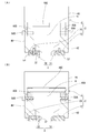
- FIG. 7A is a cross-sectional view schematically showing a cut surface of the gripping device of Embodiment 1 cut in a plane direction orthogonal to the width direction, and FIG. 7A is a cross-sectional view cut at the center position of the support portion; 7 (B) is a cross-sectional view cut at the position of the elastic member.
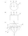
- FIG. 11A is a plan view illustrating an object gripped by the gripping device of the comparative example
- FIG. 11B is a front view of the target object
- FIG. 11C is a comparative example. It is a top view which illustrates the state which is going to hold
- Embodiment 1 which is an example which actualized the holding
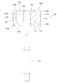
- the gripping device 1 has an appearance as shown in FIG. 1 and is configured as a device that grips a workpiece 100 as shown in FIG.
- a workpiece 100 illustrated in FIG. 2 corresponds to an example of an object, and is an article that is gripped by the gripping device 1.
- the use of the workpiece 100 is not limited, and various parts of various products can be the workpiece 100.
- the scene in which the gripping device 1 grips the workpiece 100 is not particularly limited, and the gripping device 1 can be used for various product manufacturing processes, inspection processes, transport processes, and the like.
- the gripping device 1 illustrated in FIG. 1 can be moved in multiple directions by a moving device such as a robot (not shown). For example, both in the vertical direction and in the horizontal direction perpendicular to the vertical direction. It can be moved.
- the moving device moves the gripping device 1 while the gripping device 1 is gripping the workpiece 100 as shown in FIG. 4, and the gripped workpiece 100 enters the hole 122 formed in the body 120.
- the gripping device 1 can be guided to the body 120 side so as to be in a state. Then, after the workpiece 100 enters the hole 122 by such movement, the workpiece 100 is assembled to the body 120 by the gripping device 1 releasing the grip of the workpiece 100.
- the vertical direction of the gripping device 1 shown in FIG. 1 is a direction orthogonal to a moving direction in which a pair of gripping members 10 and 20 described later approach and separate from each other, and these gripping members 10 and 20 It is a direction orthogonal to the width direction of 20.
- the moving direction of the gripping members 10 and 20 is also referred to as the left-right direction
- the width direction of the gripping members 10 and 20 is also referred to as the front-back direction.
- the up-down direction of the holding device 1 is conceptually indicated by an arrow F1.
- the left-right direction, which is the moving direction of the gripping members 10, 20, is conceptually indicated by an arrow F2
- the front-back direction which is the width direction of the gripping members 10, 20, is conceptually indicated by an arrow F3.
- the workpiece 100 gripped by the gripping device 1 has a configuration in which a plurality of parts are combined, and has three protruding portions 104A, 106A, and 108A protruding to one side.
- the workpiece 100 includes three shaft portions 104, 106, and 108 and a main body portion 102 to which the three shaft portions 104, 106, and 108 are assembled.
- these three shaft portions 104, 106, 108 a part of the two shaft portions 104, 106 are protruding portions 104A, 106A that are gripped by the fixed grip portion 2 (FIG. 1 and the like) described later.
- the central shaft portion 108 corresponds to an example of “another shaft portion”, and the protruding portion 108A that is a part of the shaft portion 108 corresponds to an example of an “other protruding portion”.
- the main body 102 is configured as a cylindrical member that fits into a circular hole 122 in a plan view shown in FIG. 3 and the like, and overlaps the disk-like plate 110 and the plate 110 as shown in FIG.
- the annular member 112 is laminated in the thickness direction.
- a through-hole portion 102 ⁇ / b> C that penetrates the inside of the main body 102 in the thickness direction is formed at the center of the main body 102.
- the through-hole portion 102C has a configuration in which the first through-hole portion 112C formed in the annular member 112 and the second through-hole portion 110C formed in the plate 110 communicate with each other in the thickness direction.
- a shaft portion 108 is inserted into the through-hole portion 102C configured as described above.
- One end side of the shaft portion 108 protrudes from the upper surface 112D that is one surface in the thickness direction of the main body portion 102, and the other end side of the shaft portion 108 protrudes from the lower surface 110E that is the other surface in the thickness direction of the main body portion 102. ing.
- a pair of holes 102 ⁇ / b> A and 102 ⁇ / b> B having bottoms are formed on both sides of the main body 102 centered on the through-hole 102 ⁇ / b> C.
- the hole 102A has a configuration in which a through hole 112A formed near the outer peripheral surface of the annular member 112 and a recess 110A formed in the plate 110 so as to follow the through hole 112A are communicated in the thickness direction. It has become.
- the hole 102B has a through-hole 112B formed near the outer peripheral surface of the annular member 112 and on the opposite side of the hole 102B, and the plate 110 following the through-hole 112B.
- the recess 110 ⁇ / b> B formed in this way is communicated in the thickness direction.
- the shaft portions 104 and 106 are inserted into the pair of hole portions 102A and 102B, respectively.
- One shaft portion 104 is disposed so as to penetrate the through-hole portion 112A, and one end side is fixed to the recess portion 110A in a form inserted into the recess portion 110A, and a projecting portion 104A that protrudes from the upper surface 112D is configured on the other end side.
- the other shaft portion 106 is disposed so as to penetrate the through-hole portion 112B, and one end side is fixed to the recess portion 110B so as to be inserted into the recess portion 110B, and the other end side includes a protruding portion 106A that protrudes from the upper surface 112D.
- a protruding portion 106A that protrudes from the upper surface 112D.
- the central protrusion 108 ⁇ / b> A gripped by the movable gripper 4 (FIG. 1 or the like) described later has two protrusions 104 ⁇ / b> A and 106 ⁇ / b> A gripped by the fixed gripper 2 (FIG. 1 or the like). It is the composition arranged between. Specifically, the central axis G1 that is the center of the shaft portion 104 and the central axis G2 that is the center of the shaft portion 106 are substantially parallel, and a through-hole is formed on a virtual plane that passes through these central axes G1 and G2. The portion 102C is located, and the shaft portion 108 is arranged along this virtual plane.
- the central shaft portion 108 constituting the protruding portion 108A is combined with the main body portion 102 in a state in which separation from the protruding side of the protruding portions 104A, 106A, 108A to the opposite side is allowed. Specifically, a shaft portion 108 is inserted into the through-hole portion 102C of the main body portion 102, and the shaft portion 108 and the main body portion 102 are allowed to move in the hole direction within the through-hole portion 102C. It is combined.
- the three shaft portions 104, 106, and 108 are assembled to the main body portion 102. It protrudes from the upper surface 112D of the annular member 112 which is an end surface. Furthermore, since the shaft portions 104 and 106 are fixed to the plate 110 that forms the bottom of the main body portion 102, the plate 110 and the annular member that is supported by the plate 110 are supported by hanging the projecting portions 104A and 106A. 112 can be suspended integrally.
- the shaft portion 108 is not fixed to the main body portion 102 and is assembled in a state where it can move in the through hole portion 102C in the hole direction. That is, if only the protruding portions 104A and 106A are gripped and the gripping of the shaft portion 108 is insufficient, the shaft portion 108 comes out of the through-hole portion 102C as shown in FIG. . Because of such a configuration, when gripping the workpiece 100, it is necessary not only to grip the protrusions 104A and 106A, but also to securely grip the protrusion 108A. This means is realized by the fixed grip 2 and the movable grip 4.
- the gripping device 1 includes a fixed gripping portion 2 and a movable gripping portion 4, and the three protrusions 104 ⁇ / b> A and 106 ⁇ / b> A of the workpiece 100 shown in FIG. , 108A is sandwiched and held. Then, the gripping device 1 is moved by a moving device (not shown) with the three gripping portions 104A, 106A, and 108A sandwiched between the fixed gripping portion 2 and the movable gripping portion 4, and is moved together with the workpiece 100 as shown in FIG. It is supposed to be carried to a position.
- the fixed grip portion 2 includes a pair of gripping members 10 and 20 and a driving device 6 that moves the gripping members 10 and 20 closer to and away from each other.
- the grip member 10 is formed with a pair of pressing portions 12A and 12B in a fixed positional relationship
- the grip member 20 is formed with a pair of pressing portions 22A and 22B in a fixed positional relationship.
- These grip members 10 and 20 are arranged in such a manner that the opposing wall portion 10A in which the pressing portions 12A and 12B are formed and the opposing wall portion 20A in which the pressing portions 22A and 22B are formed face each other.
- the driving device 6 can perform an operation of bringing the pair of gripping members 10 and 20 closer to each other and an operation of separating them from each other.
- the driving device 6 includes arms 42 and 44 that are fixed to the gripping members 10 and 20 and linearly moves the arms 42 and 44 in the left-right direction. And a linear actuator 46 to be operated.
- the arm 42 is fixed to the gripping member 10 by a plurality of connecting shaft portions 52 (see FIG. 8), and is also fixed to the driven portion 46A by a connecting member 58A such as a screw.
- the arm 44 is fixed to the holding member 20 by a plurality of connecting shaft portions 54 and 56 (see FIG. 8), and is also fixed to the driven portion 46B by a connecting member 58B such as a screw.
- the connecting members 58A and 58B are omitted and shown in a simplified manner.
- the linear actuator 46 shown in FIG. 7 is configured as an air actuator that linearly moves the driven parts 46A and 46B using, for example, air pressure.
- the linear actuator 46 includes a driven portion 46A connected to the arm 42 and a driven portion 46B connected to the arm 44.
- the driven portions 46A and 46B are connected to the left and right guide shafts 46C. It is configured to move linearly.
- 7A and 7B the configuration of the linear actuator 46 is shown in a simplified manner, but a detailed configuration is possible as long as the gripping members 10 and 20 can be moved linearly to approach and separate from each other. Is not particularly limited.
- the driven parts 46A and 46B are kept in a state of being spaced apart at a constant interval as shown in FIGS.
- the arms 42 and 44 connected to the driven parts 46A and 46B and the gripping members 10 and 20 connected to the arms 42 and 44 are also separated to some extent.
- the driven parts 46A and 46B are driven by an air cylinder (not shown), and each of the driven parts 46A and 46B includes a pair of gripping members 10 and 20. It moves linearly in the left-right direction so as to approach the center position B in the left-right direction.
- the driven parts 46A and 46B approach each other, and the arms 42 and 44 connected to the driven parts 46A and 46B and the gripping members 10 and 20 connected to the arms 42 and 44 also approach each other. Will do.
- the holding member 10 is formed with a pair of pressing portions 12 ⁇ / b> A and 12 ⁇ / b> B in a certain positional relationship with an interval in the width direction of the holding member 10.
- Each of the pressing portions 12 ⁇ / b> A and 12 ⁇ / b> B is configured as a depression that is recessed to the opposite side of the gripping member 20 in the facing wall portion 10 ⁇ / b> A of the gripping member 10.
- Each of the holding portions 12A and 12B has a groove-like configuration extending in the up-down direction, and a cross-sectional shape at a cutting plane orthogonal to the up-down direction is V-shaped.
- Each of the pressing portions 12A and 12B has a configuration in which an inner wall surface inclined with respect to the left-right direction is paired in the width direction of the gripping member 10, and an angle formed by both inner wall surfaces in the recess is 90, for example. It is a degree.
- a pair of pressing portions 22 ⁇ / b> A and 22 ⁇ / b> B are formed in the holding member 20 with a certain positional relationship with a gap in the width direction of the holding member 20.
- Each of the pressing portions 22 ⁇ / b> A and 22 ⁇ / b> B is configured as a depression that is recessed to the opposite side of the gripping member 10 in the facing wall portion 20 ⁇ / b> A of the gripping member 20. As shown in FIG.
- each of the pressing portions 22A and 22B has a groove-like configuration extending in the up-down direction, and a cross-sectional shape at a cut surface perpendicular to the up-down direction is V-shaped.
- each of the pressing portions 22 ⁇ / b> A and 22 ⁇ / b> B has a recess in which the inner wall surface inclined with respect to the left-right direction is paired in the width direction of the gripping member 20. Is 90 degrees, for example.
- the fixed gripping portion 2 configured as described above can grip the projecting portions 104A and 106A on both sides of the workpiece 100 in a combined state as shown in FIGS. Specifically, as shown in FIG. 8, the driving device 6 is driven in a state where the protruding portion 104A is disposed between the pressing portions 12A and 22A and the protruding portion 106A is disposed between the pressing portions 12B and 22B. Then, as shown in FIG. 10, the pair of gripping members 10 and 20 approach each other, the protruding portion 104A is sandwiched between the two pressing portions 12A and 22A facing each other, and the protruding portion 106A is formed by the two pressing portions 12B and 22B facing each other. Sandwiched. With such a configuration, the fixed grip portion 2 can grip the two projecting portions 104A and 106A of the workpiece 100.
- the movable gripping part 4 includes a support part 14 configured as a part of the gripping member 10 and an adjustment part 30 assembled to the gripping member 20.
- the adjustment portion 30 is formed with a support portion 34 capable of gripping the protruding portion 108A, and the support portion 34 and the support portion 14 forming a part of the gripping member 10 are arranged in a pair in the left-right direction.
- the pair of support portions 14 and 34 are configured to be interlocked with the gripping operation by the fixed grip portion 2, and sandwich the projection portion 108A different from the projection portions 104A and 106A sandwiched by the fixed grip portion 2. It has a configuration.
- one support portion 14 of the pair of support portions 14 and 34 is formed as a part of the gripping member 10, and the two pressing portions 12 ⁇ / b> A and 12 ⁇ / b> B formed on the gripping member 10. It is arranged between.
- the support portion 14 corresponds to an example of “one support portion”, and the positional relationship between the two pressing portions 12A and 12B is fixed in the gripping member 10 corresponding to an example of “one member”.
- the support portion 14 is configured as a recess recessed on the opposite side of the gripping member 20 in the facing wall portion 10A of the gripping member 10, and has a groove-like configuration extending in the vertical direction.
- the cross-sectional shape is V-shaped.
- the support portion 14 has a recess in which the inner wall surfaces 14A and 14B inclined with respect to the left-right direction are paired in the width direction of the gripping member 10, and the angle formed by the inner wall surfaces 14A and 14B in the recess is the same. For example, it is 90 degrees.
- the other support portion 34 is configured as a part of the adjustment portion 30, and is between the two pressing portions 22 ⁇ / b> A and 22 ⁇ / b> B formed on the grip member 20. And is opposed to the support 14 formed on the gripping member 10 in a pair.
- the support portion 34 corresponds to an example of “another support portion”, and is configured to be held by the gripping member 20 corresponding to “another member” and to be allowed to change its position with respect to the gripping member 20. Yes.
- the adjustment unit 30 is a part configured to allow the support unit 34 to move and to assemble the support unit 34 to the gripping member 20 and generate a biasing force toward the support unit 14 in the support unit 34.
- the adjusting portion 30 includes a moving member 32, coil springs 36A and 36B as elastic members, and a connecting shaft portion 54.
- the movement direction of the gripping member 20 (the horizontal direction is the direction of the arrow F ⁇ b> 2 shown in FIG. 8).
- a groove portion 24 extending in the direction is formed.
- the moving member 32 is fitted into the groove 24 and guided by the groove 24 and can move in the left-right direction.
- the inner wall portions 24B and 24C on both sides in the width direction of the groove portion 24 are linearly formed so as to extend in the left-right direction.
- the side wall portions 32B and 32C are linearly formed at positions where they contact the inner wall portions 24B and 24C of the groove portion 24 in the left-right direction.
- the moving member 32 moves in the left-right direction in such a manner that the side wall portions 32B, 32C are guided by the inner wall portions 24B, 24C.
- the groove portion 24 is configured as a concave portion that is recessed toward the opposite side to the gripping member 10 with the position of the facing wall portion 20A shown in FIG. 9A as an end portion, and as shown in FIG.
- the inner wall portion 24D and the lower inner wall portion 24E are linearly formed so as to extend in the left-right direction.
- the upper wall portion 32D and the lower wall portion 32E are linearly formed on the both sides in the vertical direction of the moving member 32 so as to contact the inner wall portions 24D and 24E of the groove portion 24 in the left-right direction. ing.
- the moving member 32 moves in the left-right direction such that the upper wall portion 32D and the lower wall portion 32E are guided by the inner wall portions 24D and 24E.
- the moving member 32 is restricted in relative movement in the vertical direction and in the width direction with respect to the gripping member 20, and can move relative to the gripping member 20 only in the left-right direction. ing. Further, the moving member 32 moves relative to the gripping member 20 in a state where the angles of the inner wall surfaces 34A and 34B with respect to the moving direction (left-right direction) of the gripping member 20 are maintained.
- the moving member 32 is formed with a long hole portion 32A penetrating in the vertical direction and long in the left-right direction, and inside the long hole portion 32A as shown in FIG. 9B.
- the connecting shaft portion 54 fixed to the arm 44 and the gripping member 20 penetrates in a vertically extending manner.
- the position of the connecting shaft portion 54 with respect to the gripping member 20 is fixed, and the elongated hole portion 32A moves in the left-right direction while the position in the width direction is determined by the connecting shaft portion 54.
- the support portion 34 is formed as a part of the moving member 32, and the relative position of the support portion 34 with respect to the pressing portions 22 ⁇ / b> A and 22 ⁇ / b> B changes as the moving member 32 moves in the groove portion 24. It has become.
- the support portion 34 is configured as a recess that is recessed on the opposite side to the gripping member 10 in the wall portion of the moving member 32 on the gripping member 10 side, and has a groove-like configuration extending in the vertical direction, and is cut perpendicular to the vertical direction.
- the cross-sectional shape on the surface is V-shaped.
- the support portion 34 has a recess in which the inner wall surfaces 34A and 34B inclined with respect to the left-right direction are paired in the width direction of the gripping member 20, and the angle formed by the inner wall surfaces 34A and 34B in the recess is the same. For example, it is 90 degrees.
- stepped walls 32F and 32G are formed on both sides in the width direction on the opposite side of the moving member 32 from the gripping member 10 (FIG. 8).
- a coil spring 36A as an elastic member is disposed between the one wall portion 32F and the end portion 24A in the left-right direction of the groove portion 24.
- a coil spring 36B as an elastic member is disposed between the other wall portion 32G and the end portion 24A.
- the coil springs 36A and 36B are elastically pressed against the protruding portion 108A by the moving member 32. Power is continuously generated. That is, while the pair of support portions 14 and 34 sandwich the protruding portion 108A, the moving member 32 is continuously pushed toward the protruding portion 108A by the coil springs 36A and 36B, and the moving member 32 is moved to the protruding portion 108A. Will continue to be pressed.
- the gripping device 1 has the protruding portion 104A disposed between the pressing portions 12A and 22A, the protruding portion 106A disposed between the pressing portions 12B and 22B, and the protruding portion 108A serving as the support portions 14 and 34.
- the drive of the drive device 6 is started in the state of being disposed between.
- the center of the shaft portion 104 is placed on a virtual plane passing through the deepest position P11 of the recess that is the center position in the width direction of the pressing portion 12A and the deepest position P21 of the recess that is the center position in the width direction of the pressing portion 22A.
- the central axis G2 of the shaft portion 106 is positioned on a virtual plane passing through the deepest position P12 of the depression that is the center position in the width direction of the pressing portion 12B and the deepest position P22 of the depression that is the center position in the width direction of the pressing portion 22B. It is arranged to do.
- the protruding portion 108 ⁇ / b> A is positioned between the support portions 14 and 34.
- the arrangement positions of the projecting portions 104A, 106A, and 108A of the workpiece 100 in the work space are determined, and the projecting portions 104A, 106A, and 108A of FIG.
- the gripping device 1 may be moved by a moving device (not shown) so as to be arranged. Further, when the workpiece 100 is arranged as shown in FIG. 8, the main body 102 and the shaft 108 are held in a fixed relationship so that the shaft 108 shown in FIG. It is desirable to use means.
- the fixed grip portion 2 drives the drive device 6 in the arrangement state as shown in FIG. 8 to bring the pair of grip members 10 and 20 closer to each other.
- these opposing wall parts 10A and 20A approach three protrusion part 104A, 106A, 108A.
- the pressing portion 12 ⁇ / b> A formed on the gripping member 10 and the pressing portion 22 ⁇ / b> A formed on the gripping member 20 approach each other and sandwich the protruding portion 104 ⁇ / b> A.
- the pressing portion 12B formed on the gripping member 10 and the pressing portion 22B formed on the gripping member 20 approach each other and sandwich the protruding portion 106A.
- the pair of support portions 14 and 34 constituting the movable gripping portion 4 approach each other in conjunction with the approaching operation of the gripping members 10 and 20 as shown in FIG. 10, and the protruding portions 104A and 106A sandwiched by the fixed gripping portion 2 and Sandwiches a different central protrusion 108A.
- the three projecting portions 104A, 106A, 108A formed on the workpiece 100 are all gripped.
- the support portion 34 that forms a part of the adjusting portion 30 is allowed to move in the left-right direction relative to the gripping member 20, and exerts an urging action that continuously pushes the protruding portion 108 ⁇ / b> A when the protruding portion 108 ⁇ / b> A is sandwiched. It has become. For this reason, even if the central axis G3 of the shaft portion 108 is slightly deviated from the normal position in the stage before gripping as shown in FIG. 8, the support portion 34 receives the displaced shaft portion 108 with a certain degree of shock absorption. However, the support portion 14 is stably sandwiched.
- the gripping device 1 is advantageous when gripping an object such as the workpiece 100 described above (that is, an object in which the intermediate protrusion 108A is likely to be displaced with respect to the protrusions 108B and 108C on both sides). It is a simple configuration.
- the protrusions 104A, 106A, and 108A provided on the workpiece 100 can be more securely sandwiched and stably held.
- the plurality of pressing portions 12A, 12B, 22A, and 22B of the fixed grip portion 2 are disposed on both sides, gripping can be further stabilized.
- the gripping device 1 causes the pair of gripping members 10 and 20 to approach each other as shown in FIG. 9 and is formed on the plurality of pressing portions 12A and 12B formed on one gripping member 10 and the other gripping member 20.
- the two protruding portions 104A and 106A of the workpiece 100 can be sandwiched between the plurality of holding portions 22A and 22B.
- the pair of support portions 14, 34 of the movable gripping portion 4 approach each other in conjunction with the approaching action of the pair of gripping members 10, 20 provided in the fixed gripping portion 2, and projecting portions 104 ⁇ / b> A sandwiched by the fixed gripping portion 2.
- 106A can be sandwiched. That is, the fixed grip portion 2 and the movable grip portion 4 can grip all of the at least three projecting portions 104A, 106A, and 108A formed on the workpiece 100.
- the support portion 34 provided in the movable gripping portion 4 is allowed to change its position with respect to the plurality of pressing portions 22A and 22B formed on the gripping member 20 interlocked therewith. Further, the support portion 34 is configured to continuously push the protruding portion 108A by applying the elastic force of the coil springs 36A and 36B when the protruding portion 108A is sandwiched. Because of such a configuration, even if the position of the protrusion 108A sandwiched by the movable gripper 4 is slightly shifted from the protrusions 104A and 106A sandwiched by the fixed gripper 2, the support part 34 is allowed to change its position.
- the movable gripper 4 can automatically adjust the position of the support portion 34 in accordance with the positional deviation of the protrusion 108A, and the force for pushing the protrusion 108A to the support portion 34 even at the adjusted position. Therefore, the protrusion 108A can be gripped with a sufficient gripping force.
- the gripping device 1 can grip the workpiece 100 while sandwiching the three protrusions 104A, 106A, and 108A provided on the workpiece 100, and suppresses the displacement even when the protrusion 108A is displaced. It can be securely gripped in an open shape.
- the support portion 14 is formed in a form in which the positional relationship between the gripping member 10 and the plurality of pressing portions 12 ⁇ / b> A and 12 ⁇ / b> B is fixed.
- the support portion 34 is configured to be held by the gripping member 20 and to be allowed to change its position with respect to the gripping member 20. If the gripping device 1 is configured in this manner, the gripping member 10 may be configured so as not to change the positional relationship between the plurality of pressing portions 12A and 12B and the support portion 14.
- the gripping member 10 does not need to be provided with a structure for moving the support portion 14 relative to the plurality of pressing portions 12A and 12B, and the configuration can be simplified. Moreover, on the gripping member 10 side, the support portion 14 that supports the protruding portion 108A and the pressing portions 12A and 12B that support the other protruding portions 108B and 108C are fixed. For this reason, the protrusions 108A, 108B, and 108C supported by these can be positioned more accurately according to the fixed positional relationship.
- the workpiece 100 is configured to be combined in a state in which the shaft portion 108 is detachable from the main body portion 102 among the plurality of shaft portions 104, 106, 108 to be gripped. Therefore, it is required to grip the shaft portion 108 more reliably. This is because when the plurality of shaft portions 104, 106, and 108 of the workpiece 100 are sandwiched and gripped, if the shaft portion 108 that can be detached is not sufficiently sandwiched, This is because it falls off from 102.
- the movable gripping portion 4 grips the protruding portion 108 ⁇ / b> A that forms at least a part of the shaft portion 108 that is combined in a detachable state with respect to the main body portion 102 with a sufficient gripping force. Yes.
- the support portion 34 can be adjusted with sufficient gripping force while automatically adjusting the position according to the misalignment. It can be surely prevented.
- the above-described gripping device 1 is more effective when gripping the workpiece 100 as shown in FIG. 5 and assembling it to the body 120 as shown in FIG.
- the workpiece 100 when the outer peripheral portion of the main body 102 is gripped by the workpiece 100 without gripping the shaft portions 104 and 106 on both sides, the two shaft portions 104 and 106 and the plate 110 are separated. It is a configuration that falls. Furthermore, the workpiece 100 also has a configuration in which the shaft portion 108 falls off from the main body portion 102 unless the shaft portion 108 is securely gripped. For this reason, when the work 100 is assembled in the hole 122, the place where the workpiece 100 is gripped is limited to the projecting portions 104A, 106A, 108A, and assembly is required while securely gripping these. In addition, since the workpiece 100 has a configuration in which the shaft portion 108 is not completely fixed, the workpiece 100 is also likely to be displaced.
- the above-described gripping device 1 is very effective because it can reliably grip a limited place in the assembly where the gripping place is limited and the positional shift is likely to occur in some gripping places.
- assembly of the workpiece 100 having large restrictions can be automated without relying on manual work, and errors caused by manual work can be eliminated and time can be reduced.
- the present invention is not limited to the first embodiment described with reference to the above description and drawings.
- the following embodiments are also included in the technical scope of the present invention.
- gripping part what is necessary is just to pinch
- the moving member 32 may be slightly allowed to move in the width direction orthogonal to the moving direction of the gripping member 20.
- the configuration in which the wall portion of the moving member 32 and the opposing wall portion 20A of the gripping member 20 are aligned as illustrated in FIG. 8 when not in the gripping state is illustrated.
- the wall portion of the moving member 32 may not be aligned with the opposing wall portion 20 ⁇ / b> A of the gripping member 20.
- the moving member 32 is provided only on one gripping member 20 side. However, the moving member is provided so as to be held by both gripping members, and each moving member has a support portion. May be formed.
- the workpiece 100 provided with the protruding portion 108A gripped by the movable gripping portion 4 between the protruding portions 104A, 106A gripped by the fixed gripping portion 2 is set as a gripping target. It is not limited to such a configuration.
- a protruding portion that is held by the movable holding portion may be provided outside the plurality of protruding portions that are held by the fixed holding portion.
- each support part which comprises a movable holding part should just be arrange
- the gripping member 10 is configured by one component.
- the gripping member 10 is configured by two or more components. Also good. Similarly, the gripping member 20 is composed of one component, but the gripping member 20 may be composed of two or more components as long as the holding portions 22A and 22B are fixed in a positional relationship.
- the driving device 6 including an air actuator is illustrated as an approaching operation unit that causes the gripping members 10 and 20 to approach each other, and the gripping members 10 and 20 are linearly moved by the driving device 6.
- an example of driving is shown in FIG. 1, this example is merely an example.
- the gripping members 10 and 20 may be linearly driven by a linear actuator other than the air actuator.
- the driving device 6 may use an actuator other than the linear actuator, and may transmit the driving force to one or both of the gripping members 10 and 20 so as to approach and separate them.
- the approaching operation unit that causes the gripping members 10 and 20 to approach each other is not limited to the driving device 6 described above.
- a force may be applied to one or both of the gripping members 10 and 20 by one or a plurality of elastic members such as springs, and a continuous force in the approach direction may be generated in one or both.
- one or a plurality of mechanisms for generating a force in a predetermined direction by fitting a screw-like member into the screw groove and transmitting such force directly or indirectly to the gripping members 10 and 20 One or both of them may generate a continuous force in the approach direction.
- both the pressing portion and the support portion have an inner wall angle of 90 degrees, but may be an acute angle or an obtuse angle.
- each of the pressing portion and the support portion is configured in a V shape when viewed in plan, but may be configured in a U shape when viewed in plan. It may be a step shape other than that.
- the moving member 32 is configured to move relative to the gripping member 20 in a state in which the angles of the inner wall surfaces 34A and 34B with respect to the moving direction of the gripping member 20 are maintained.
- a configuration in which the angles of the inner wall surfaces 34 ⁇ / b> A and 34 ⁇ / b> B can slightly change with respect to the moving direction of the gripping member 20 may be adopted.
Landscapes
- Engineering & Computer Science (AREA)
- Mechanical Engineering (AREA)
- Robotics (AREA)
- Manipulator (AREA)
- Jigs For Machine Tools (AREA)
- Gripping Jigs, Holding Jigs, And Positioning Jigs (AREA)
- Automatic Assembly (AREA)
- Feeding Of Workpieces (AREA)
Abstract
対象物に設けられた少なくとも3つの突出部を挟み込む形で対象物を把持することができ、且つ突出部に位置ずれが生じる場合でも確実に把持することができる把持装置を提供する。 把持装置(1)において固定把持部(2)は、一対の把持部材(10,20)を互いに接近させ、把持部材(10)の2つの押さえ部(12A,12B)と把持部材(20)の2つの押さえ部(22A,22B)とによってワーク(100)の2つの突出部(104A,106A)をそれぞれ挟む。可動把持部(4)は、一対の把持部材(10,20)の接近動作に連動して互いに近づく一対の支持部(14,34)を備え、支持部(14,34)によって突出部(108A)を挟む。一方の支持部(34)は、把持部材(20)の2つの押さえ部(22A,22B)に対して位置変化が許容され、突出部(108A)の挟み込み時に外部からの弾性力が付加されて突出部(108A)を継続的に押す。
Description
本発明は把持装置に関するものである。
特許文献1には、径が異なる複数種類の被把持部材を把持し得る把持治具が開示されている。この把持治具は、被把持部材を把持するための2つの把持部材と、2つの把持部材を付勢する弾性部材と、2つの把持部材をスライド操作するための操作軸とを備えている。この把持冶具は、2つの把持部材を離間させるように操作軸を操作し得る構成となっており、2つの把持部材の間隔を広げることで、それらの間に様々な径の被把持部材を挿入し得る構成となっている。そして、2つの把持部材が離間した状態で被把持部材が挿入され、その後に操作軸に対する操作が解除されると、弾性力によって2つの把持部材が互いに接近する方向に押圧され、2つの把持部材によって被把持部材が安定的に保持されるようになっている。
しかし、特許文献1の把持治具は、1つの軸部材のみを把持すること目的としているため、2以上の部分を把持すべき対象物には適用できず、このような対象物で生じる特有の問題には対応できない。例えば、把持の対象物品としては、図11(A)(B)のように3つの突出部S1,S2,S3を備えるような対象物Wも想定され、場合によっては、突出部S1,S2,S3を挟み込んで把持することが望ましいこともあり得る。けれども、特許文献1の把持冶具では、このような要求に応えることはできない。
図11(A)(B)のような対象物Wを把持の対象とし、3つの突出部S1,S2,S3を挟み込んで把持し得る装置としては、図11(C)で示すような把持装置Mが挙げられる。図11(C)の把持装置Mは、一対の把持部材C1,C2を接近及び離間させ得る構成となっており、対象物Wを把持する場合には、図11(C)で示す二点鎖線のように一対の把持部材C1,C2を互いに接近させる。そして、このような接近動作がなされると、一対の把持部材C1,C2が各凹部D1,D2によって3つの突出部S1,S2,S3を挟み込み、例えば吊り下げる形で対象物Wを把持する。このような把持装置Mを用いれば、3つの突出部S1,S2,S3が正規の位置関係である限り、一対の把持部材C1,C2が各凹部D1,D2によって3つの突出部S1,S2,S3を確実に挟み込んで把持することができる。
しかし、図11(C)の把持装置Mは、一対の把持部材C1,C2に形成される各凹部D1,D2の配置が、3つの突出部S1,S2,S3の正規の位置関係に完全に合わせた固定配置となっている。このため、3つの突出部S1,S2,S3のいずれかに位置ずれが生じると、把持部材C1,C2に形成された凹部は、位置ずれした突出部を正常に挟むことができなくなり、このような不安定な把持状態のまま対象物Wが吊り下げられてしまう虞がある。
本発明は、上述した実情に鑑みてなされたものであって、対象物に設けられた少なくとも3つの突出部を挟み込む形で対象物を把持することができ、且つ突出部に位置ずれが生じる場合でも確実に把持することができる把持装置を提供することを解決すべき課題としている。
本発明の把持装置は、複数の部品を有し且つ3以上の突出部が一方側に突出した構成の対象物を把持の対象とし、複数の押さえ部が互いに固定された位置関係で形成された把持部材が対をなして備えられた固定把持部を有する。固定把持部は、一対の把持部材を互いに接近させて、一方の把持部材に形成された複数の押さえ部と他方の把持部材に形成された複数の押さえ部とによって対象物の少なくとも2つの突出部をそれぞれ挟む構成である。更に、把持装置は、一対の把持部材の接近動作に連動して互いに近づく構成をなし且つ固定把持部が挟む突出部とは異なる他の突出部を挟む構成をなす一対の支持部を備えた可動把持部を有する。そして、少なくともいずれかの支持部は、連動する把持部材に形成された複数の押さえ部に対して位置変化が許容された構成であり且つ一対の支持部による他の突出部の挟み込み時に弾性部材の弾性力が付加されて他の突出部を継続的に押す構成である。
この把持装置の固定把持部は、一対の把持部材を互いに接近させ、一方の把持部材に形成された複数の押さえ部と他方の把持部材に形成された複数の押さえ部とによって対象物の少なくとも2つの突出部をそれぞれ挟むことができる。また、可動把持部は、固定把持部における一対の把持部材の接近動作に連動させて一対の支持部を接近させ、固定把持部が挟む突出部とは異なる他の突出部を挟むことができる。つまり、固定把持部及び可動把持部によって、対象物に構成された少なくとも3つの突出部をいずれも把持することができる。しかも、可動把持部に備えられた少なくともいずれかの支持部は、連動する把持部材に形成された複数の押さえ部に対して位置変化が許容されており且つ「他の突出部」の挟み込み時には弾性部材の弾性力が付加されて「他の突出部」を継続的に押す構成となっている。このような構成であるため、固定把持部が挟む突出部に対して、可動把持部が挟む「他の突出部」の位置が若干ずれたとしても、位置変化が許容された支持部が位置ずれに合わせて変位し、変位後の位置で他の突出部を継続的に押し続けることになる。つまり、可動把持部は、「他の突出部」の位置ずれに合わせて支持部の位置調整を自動的に行うことができ、調整後の位置でも支持部には「他の突出部」を押すための力が継続的に付与され続けるため、「他の突出部」を十分な把持力で把持することができる。
このように、把持装置は、対象物に設けられた少なくとも3つの突出部を挟み込む形で対象物を把持することができ、且つ突出部に位置ずれが生じる場合でも位置ずれの影響を抑えた形で突出部を確実に把持することができる。
本発明の把持装置の把持対象となる対象物は、可動把持部に把持される他の突出部の両側に固定把持部に把持される突出部が配置されていてもよい。そして、一対の支持部における一方の支持部の両側に一方の把持部材に形成された押さえ部が配置され、他方の支持部の両側に他方の把持部材に形成された押さえ部が配置されていてもよい。
このように構成される把持装置では、固定把持部が、対象物に構成された3以上の突出部のうちの両側の突出部を挟むように動作する。そして、可動把持部は、位置変化が許容された支持部での位置調整作用及び付勢作用を生じさせながら、中間の突出部(他の突出部)を把持することになる。つまり、この把持装置は、3以上の突出部を備え且つ中間の突出部が両側の突出部に対して位置ずれしやすい対象物を把持する場合に有利な構成であり、このような対象物に設けられた3以上の突出部をより確実に挟み込んで安定的に把持することができる。しかも、固定把持部の複数の押さえ部が両側に配置された位置関係であるため、把持をより安定化させることができる。
本発明の把持装置において、一対の支持部のいずれか一の支持部は、一対の把持部材のいずれか一の部材において複数の押さえ部との位置関係が固定された形で形成されていてもよい。そして、一対の支持部のいずれか他の支持部は、一対の把持部材のいずれか他の部材に保持されるとともに他の部材に対して位置変化が許容された構成であってもよい。
このように把持装置を構成すれば、一対の把持部材のうち、いずれか「一の部材」の構成を、複数の押さえ部と支持部との位置関係を変化させない構成とすることができる。つまり、この「一の部材」は、複数の押さえ部に対して支持部を相対移動させるための構造が設けられず、構成の簡易化が図られる。しかも、「一の部材」の側では、「他の突出部」を支持する支持部と、それ以外の突出部を支持する複数の押さえ部とが固定された位置関係であるため、これらの突出部を固定された位置関係に合わせてより正確に位置決めすることができる。
本発明の把持装置の把持対象となる対象物は、3以上の軸部と、3以上の軸部が組み付けられる本体部とを有していてもよい。そして、3以上の軸部のうち、いずれか複数の軸部の少なくとも一部が固定把持部に把持される突出部であり、固定把持部に把持される複数の軸部とは異なる他の軸部の少なくとも一部が可動把持部に把持される他の突出部であってもよい。そして、可動把持部に把持される他の軸部は、本体部に対して突出部の突出側とは反対側への離脱が許容された状態で組み合わせられる軸部であってもよい。
把持の対象部分となる複数の軸部のうち、いずれかの軸部が本体部に対して離脱可能な状態で組み合わせられる対象物では、この軸部をより確実に把持することが求められる。なぜなら、このような対象物の複数の軸部を把持装置で挟み込んで把持する場合、離脱し得る軸部の挟み込みが不十分であると、この軸部が把持の際に本体部から抜け落ちてしまうからである。これに対し、上述した把持装置では、本体部に対して離脱可能な状態で組み合わせられる「他の軸部」を可動把持部によって十分な把持力で把持することができる。特に、「他の軸部」に位置ずれが生じても、その位置ずれに合わせて支持部の位置調整を自動的に行いつつ十分な把持力で把持することができるため、「他の軸部」の離脱をより確実に防止することができる。
<実施形態1>
本発明の把持装置を具体化した一例である実施形態1について、図面を参照しつつ説明する。
本発明の把持装置を具体化した一例である実施形態1について、図面を参照しつつ説明する。
まず、図1等で示す把持装置1の概要や用途等を説明する。
実施形態1の把持装置1は、図1のような外観をなし、図2のようなワーク100を把持する装置として構成されている。図2で示すワーク100は、対象物の一例に相当し、把持装置1によって把持される物品である。ワーク100の用途は限定されず、様々な製品の様々な部品がワーク100となり得る。また、把持装置1がどのような場面でワーク100を把持するのかは特に限定されず、様々な製品の製造工程、検査工程、搬送工程などに利用し得る。
実施形態1の把持装置1は、図1のような外観をなし、図2のようなワーク100を把持する装置として構成されている。図2で示すワーク100は、対象物の一例に相当し、把持装置1によって把持される物品である。ワーク100の用途は限定されず、様々な製品の様々な部品がワーク100となり得る。また、把持装置1がどのような場面でワーク100を把持するのかは特に限定されず、様々な製品の製造工程、検査工程、搬送工程などに利用し得る。
以下では、図1で示す把持装置1が、図3のようなボディ120に組み付ける装置の一部として構成された例を挙げて説明する。この図3の例では、例えば図示しないロボット(robot)等の移動装置により、把持装置1が多方向に移動可能とされており、例えば、上下方向にも、上下方向と直交する水平方向にも移動可能とされている。この移動装置は、例えば、図4のように把持装置1がワーク100を把持している状態で把持装置1を移動させ、把持されたワーク100がボディ120に形成された孔部122に入り込んだ状態となるように把持装置1をボディ120側に案内し得る。そして、このような移動により、ワーク100が孔部122に入り込んだ状態となった後、把持装置1がワーク100の把持を解除することでワーク100がボディ120に組み付けられるようになっている。
なお、本明細書において、図1で示す把持装置1の上下方向とは、後述する一対の把持部材10,20が互いに接近及び離間する移動方向と直交する方向であり、且つこれら把持部材10,20の幅方向と直交する方向である。以下では、把持部材10,20の移動方向を左右方向とも称し、把持部材10,20の幅方向を前後方向とも称して説明する。また、図4では、把持装置1の上下方向を矢印F1で概念的に示す。図8では、把持部材10,20の移動方向である左右方向を矢印F2によって概念的に示し、把持部材10,20の幅方向である前後方向を矢印F3によって概念的に示す。
次に、把持装置1によって把持されるワーク100を詳述する。
図5で示すように、把持対象となるワーク100は、複数の部品が組み合わせられた構成をなし、且つ3つの突出部104A,106A,108Aが一方側に突出した構成となっている。図5のように、このワーク100は、3つの軸部104,106,108と、3つの軸部104,106,108が組み付けられる本体部102とを有している。これら3つの軸部104,106,108のうち、2つの軸部104,106の一部が、後述する固定把持部2(図1等)に把持される突出部104A,106Aとなっている。そして、固定把持部2(図1等)に把持される2つの軸部104,106とは異なる中央の軸部108の一部が、後述する可動把持部4(図1等)に把持される突出部108Aとなっている。なお、中央の軸部108は、「他の軸部」の一例に相当し、この軸部108の一部である突出部108Aは、「他の突出部」の一例に相当する。
図5で示すように、把持対象となるワーク100は、複数の部品が組み合わせられた構成をなし、且つ3つの突出部104A,106A,108Aが一方側に突出した構成となっている。図5のように、このワーク100は、3つの軸部104,106,108と、3つの軸部104,106,108が組み付けられる本体部102とを有している。これら3つの軸部104,106,108のうち、2つの軸部104,106の一部が、後述する固定把持部2(図1等)に把持される突出部104A,106Aとなっている。そして、固定把持部2(図1等)に把持される2つの軸部104,106とは異なる中央の軸部108の一部が、後述する可動把持部4(図1等)に把持される突出部108Aとなっている。なお、中央の軸部108は、「他の軸部」の一例に相当し、この軸部108の一部である突出部108Aは、「他の突出部」の一例に相当する。
本体部102は、図3等で示す平面視円形状の孔部122に嵌り込む円筒状の部材として構成され、図5のように、円板状のプレート(plate)110と、プレート110に重なる環状部材112とが厚さ方向に積層された構成をなしている。この本体部102の中心部には、本体部102の内部を厚さ方向に貫通する貫通孔部102Cが形成されている。この貫通孔部102Cは、環状部材112に形成された第1の貫通孔部112Cと、プレート110に形成された第2の貫通孔部110Cとが厚さ方向に連通した構成となっている。このように構成された貫通孔部102Cには軸部108が挿入されている。軸部108の一端側は本体部102の厚さ方向一方側の面である上面112Dから突出し、軸部108の他端側は本体部102の厚さ方向他方側の面である下面110Eから突出している。
図5で示すように、本体部102において貫通孔部102Cを中心とする両側には、底部を有する一対の孔部102A,102Bが形成されている。孔部102Aは、環状部材112の外周面の近くに形成された貫通孔部112Aと、この貫通孔部112Aに続くようにプレート110に形成された凹部110Aとが厚さ方向に連通した構成となっている。同様に、孔部102Bは、環状部材112の外周面の近くであって且つ孔部102Bとは反対側の位置に形成された貫通孔部112Bと、この貫通孔部112Bに続くようにプレート110に形成された凹部110Bとが厚さ方向に連通した構成となっている。
そして、これら一対の孔部102A,102Bには、軸部104,106がそれぞれ挿入されている。一方の軸部104は、貫通孔部112Aを貫く形で配置され、一端側が凹部110Aに挿入された形で凹部110Aに固定され、他端側には上面112Dから突出する突出部104Aが構成されている。他方の軸部106は、貫通孔部112Bを貫く形で配置され、且つ一端側が凹部110Bに挿入された形で凹部110Bに固定され、他端側には上面112Dから突出する突出部106Aが構成されている。
図5で示すワーク100において、後述する可動把持部4(図1等)に把持される中央の突出部108Aは、固定把持部2(図1等)に把持される2つの突出部104A,106Aの間に配置された構成となっている。具体的には、軸部104の中心となる中心軸線G1と軸部106の中心となる中心軸線G2とが略平行となっており、これらの中心軸線G1,G2を通る仮想平面上に貫通孔部102Cが位置し、この仮想平面に沿って軸部108が配置されている。
更に、突出部108Aを構成する中央の軸部108は、本体部102に対して突出部104A,106A,108Aの突出側とは反対側への離脱が許容された状態で組み合わせられている。具体的には、本体部102の貫通孔部102Cに軸部108が挿入されており、この軸部108は、貫通孔部102C内において孔方向への移動が許容された形で本体部102と組み合わせられている。
以上のような構成で、本体部102に対して3つの軸部104,106,108が組み付けられ、それぞれの一部をなす3つの突出部104A,106A,108Aが、本体部102の一方側の端面である環状部材112の上面112Dから突出している。更に、軸部104,106は、本体部102の底部をなすプレート110に固定されているため、突出部104A,106Aを把持しつつ吊り下げることで、プレート110とプレート110に支持される環状部材112とを一体的に吊り下げることが可能となっている。
但し、軸部108は、本体部102に固定されておらず、貫通孔部102C内を孔方向に移動し得る状態で組み付けられている。つまり、突出部104A,106Aのみを把持し、軸部108の把持が不十分であると、図6のように軸部108が貫通孔部102Cから抜けてしまい、本体部102から離脱してしまう。このような構成であるため、ワーク100を把持する場合には、突出部104A,106Aを把持するだけではなく、突出部108Aも確実に把持する必要があり、後に詳述する把持装置1では、固定把持部2と可動把持部4とによってこの手段を実現している。
次に、把持装置1の詳細な構成を説明する。
図1のように、把持装置1は、固定把持部2と可動把持部4とを備え、これら固定把持部2及び可動把持部4により、図2で示すワーク100の3つの突出部104A,106A,108Aを挟み込んで把持する構成となっている。そして、把持装置1は、固定把持部2及び可動把持部4によって3つの突出部104A,106A,108Aを挟み込んだ状態で、図示しない移動装置によって移動され、図4のようにワーク100と共に所望の位置に運ばれるようになっている。
図1のように、把持装置1は、固定把持部2と可動把持部4とを備え、これら固定把持部2及び可動把持部4により、図2で示すワーク100の3つの突出部104A,106A,108Aを挟み込んで把持する構成となっている。そして、把持装置1は、固定把持部2及び可動把持部4によって3つの突出部104A,106A,108Aを挟み込んだ状態で、図示しない移動装置によって移動され、図4のようにワーク100と共に所望の位置に運ばれるようになっている。
まず、固定把持部2について説明する。図1で示すように、固定把持部2は、一対の把持部材10,20と、これら把持部材10,20を接近及び離間させる駆動装置6とを備える。把持部材10には、固定された位置関係で一対の押さえ部12A,12Bが形成されており、把持部材20には、固定された位置関係で一対の押さえ部22A,22Bが形成されている。これら把持部材10,20は、押さえ部12A,12Bが形成された対向壁部10Aと、押さえ部22A,22Bが形成された対向壁部20Aとを向い合せた形で配置されている。
駆動装置6は、一対の把持部材10,20を互いに接近させる動作と、これらを互いに離間させる動作とを行い得る。図7(A)(B)で示すように、駆動装置6は、把持部材10,20にそれぞれ固定されるアーム(arm)42,44と、このアーム42,44を左右方向に直線的に移動させるリニアアクチュエータ(linear actuator)46とを備える。アーム42は、複数の連結軸部52(図8参照)によって把持部材10に固定されており、更に、ねじ等の連結部材58Aによって被駆動部46Aにも固定されている。アーム44は、複数の連結軸部54,56(図8参照)によって把持部材20に固定されており、更に、ねじ等の連結部材58Bによって被駆動部46Bにも固定されている。なお、図1では連結部材58A,58Bは省略し、簡略的に示している。
図7で示すリニアアクチュエータ46は、例えば、空気圧を利用して被駆動部46A,46Bを直線的に移動させるエアアクチュエータとして構成されている。このリニアアクチュエータ46は、アーム42に連結される被駆動部46Aと、アーム44に連結される被駆動部46Bとを備え、これら被駆動部46A,46Bを、左右方向のガイド軸46Cに沿って直線的に移動させる構成となっている。なお、図7(A)(B)では、リニアアクチュエータ46の構成を簡略的に示しているが、把持部材10,20を直線的に移動させ、接近及び離間させ得る構成であれば詳細な構成は特に限定されない。
リニアアクチュエータ46は、被駆動部46A,46Bを駆動させない駆動停止状態のときには、図7(A)(B)のように被駆動部46A,46Bが一定間隔に離間した状態に保たれる。そして、この駆動停止状態のときには、被駆動部46A,46Bに連結されたアーム42,44及びこのアーム42,44に連結された把持部材10,20もある程度離間している。一方、リニアアクチュエータ46が駆動動作を行うと、エアシリンダ(pneumatic cylinder:図示略)によって被駆動部46A,46Bが駆動され、被駆動部46A,46Bのいずれも、一対の把持部材10,20の左右方向中心位置Bに近づくように左右方向に直線的に移動する。そして、図4のように被駆動部46A,46Bが互いに接近し、被駆動部46A,46Bに連結されたアーム42,44及びこのアーム42,44に連結された把持部材10,20も互いに接近することになる。
また、図4のような状態のときに、リニアアクチュエータ46が駆動解除動作を行うと、エアシリンダ(図示略)によって被駆動部46A,46Bが互いに離れるように移動される。このように被駆動部46A,46Bが互いに離れると、被駆動部46A,46Bに連結されたアーム42,44及びこのアーム42,44に連結された把持部材10,20も互いに離間し、把持装置1は、図7(A)(B)のような駆動停止状態に戻る。把持装置1は、このようにして把持部材10,20の接近動作及び離間動作を行う。
図8のように、把持部材10には、一対の押さえ部12A,12Bが把持部材10の幅方向に間隔をあけて一定の位置関係で形成されている。そして、押さえ部12A,12Bのいずれも、把持部材10の対向壁部10Aにおいて、把持部材20とは反対側に窪んだ窪みとして構成されている。押さえ部12A,12Bのいずれも、上下方向に延びる溝状の構成となっており、上下方向と直交する切断面での断面形状がV字状となっている。これら押さえ部12A,12Bの各々は、左右方向に対して傾斜した内壁面が把持部材10の幅方向に対をなした構成で窪みが構成され、窪み内の両内壁面のなす角度が例えば90度となっている。同様に、把持部材20には、一対の押さえ部22A,22Bが把持部材20の幅方向に間隔をあけて一定の位置関係で形成されている。そして、押さえ部22A,22Bのいずれも、把持部材20の対向壁部20Aにおいて、把持部材10とは反対側に窪んだ窪みとして構成されている。図1で示すように、押さえ部22A,22Bのいずれも、上下方向に延びる溝状の構成となっており、上下方向と直交する切断面での断面形状がV字状となっている。図8のように、これら押さえ部22A,22Bの各々は、左右方向に対して傾斜した内壁面が把持部材20の幅方向に対をなした構成で窪みが構成され、窪み内の両内壁面のなす角度が例えば90度となっている。
このように構成される固定把持部2は、図2、図5のような組み合わせ状態とされたワーク100の両側の突出部104A,106Aを挟み込んで把持することができる。具体的には、図8のように突出部104Aを押さえ部12A,22Aの間に配置し、突出部106Aを押さえ部12B,22Bの間に配置した状態で駆動装置6を駆動する。すると、図10のように一対の把持部材10,20が互いに接近し、対向する2つの押さえ部12A,22Aによって突出部104Aが挟まれ、対向する2つの押さえ部12B,22Bによって突出部106Aが挟まれる。固定把持部2は、このような構成により、ワーク100の2つの突出部104A,106Aを把持することができる。
次に、可動把持部4について説明する。図8で示すように、可動把持部4は、把持部材10の一部として構成された支持部14と、把持部材20に組み付けられた調整部30とを備える。調整部30には、突出部108Aを把持し得る支持部34が形成され、この支持部34と、把持部材10の一部をなす支持部14とが左右方向に対をなして配置されている。これら一対の支持部14,34は、図10のように固定把持部2による把持動作と連動する構成となっており、固定把持部2が挟む突出部104A,106Aとは異なる突出部108Aを挟む構成となっている。
図8で示すように、一対の支持部14,34のうち、一方の支持部14は、把持部材10の一部として形成されており、把持部材10に形成された2つの押さえ部12A,12Bの間に配置されている。この支持部14は、「一の支持部」の一例に相当し、「一の部材」の一例に相当する把持部材10において2つの押さえ部12A,12Bとの位置関係が固定されている。支持部14は、把持部材10の対向壁部10Aにおいて、把持部材20とは反対側に窪んだ窪みとして構成され、上下方向に延びる溝状の構成であり、上下方向と直交する切断面での断面形状がV字状となっている。この支持部14は、左右方向に対して傾斜した内壁面14A,14Bが把持部材10の幅方向に対をなした構成で窪みが構成され、窪み内の両内壁面14A,14Bのなす角度が例えば90度となっている。
図8で示すように、一対の支持部14,34のうち、他方の支持部34は、調整部30の一部として構成され、把持部材20に形成された2つの押さえ部22A,22Bの間に配置されており、把持部材10に形成された支持部14と対をなす形で対向している。この支持部34は、「他の支持部」の一例に相当し、「他の部材」に相当する把持部材20に保持されるとともに把持部材20に対して位置変化が許容された構成となっている。
調整部30は、支持部34の移動を許容し得る構成で支持部34を把持部材20に組み付け、且つ支持部34において支持部14側への付勢力を発生させるように構成された部分である。この調整部30は、移動部材32と、弾性部材としてのコイルばね36A,36Bと、連結軸部54とを有する。
図8のように、把持部材20において幅方向(図8で示す矢印F3の方向)の中央位置付近には、把持部材20の移動方向(左右方向であり、図8で示す矢印F2の方向)に延びる溝部24が形成されている。図9(A)のように、移動部材32は、このような溝部24の内部に嵌り込んでおり、溝部24によって案内される構成で、左右方向に移動し得る構成となっている。具体的には、溝部24の幅方向両側の内壁部24B,24Cが左右方向に延びる形で直線的に形成されている。そして、移動部材32の幅方向両側において、溝部24の内壁部24B,24Cにそれぞれ接触する位置には、側壁部32B,32Cが左右方向に延びる形で直線的に形成されている。そして、これら側壁部32B,32Cが内壁部24B,24Cによって案内される形で、移動部材32が左右方向に移動するようになっている。
溝部24は、図9(A)で示す対向壁部20Aの位置を端部として把持部材10とは反対側に窪んだ凹部として構成され、図9(B)で示すように、溝部24の上側の内壁部24Dと下側の内壁部24Eとが左右方向に延びる形で直線的に形成されている。そして、移動部材32の上下方向両側において、溝部24の内壁部24D,24Eのそれぞれに接触する位置には、上壁部32Dと下壁部32Eとが左右方向に延びる形で直線的に形成されている。移動部材32は、これら上壁部32D及び下壁部32Eが内壁部24D,24Eによって案内される形で、左右方向に移動するようになっている。このように、移動部材32は、把持部材20に対する上下方向への相対移動及び幅方向への相対移動が規制されており、把持部材20に対しては左右方向にのみ相対移動し得る構成となっている。また、移動部材32は、把持部材20の移動方向(左右方向)に対する内壁面34A,34Bの角度が維持された状態で把持部材20対して相対的に移動するようになっている。
また、図9(A)のように、移動部材32には、上下に貫通し且つ左右方向に長い長孔部32Aが形成されており、図9(B)のように、長孔部32A内には、アーム44及び把持部材20にそれぞれ固定される連結軸部54が上下に延びた形で貫通している。把持部材20に対する連結軸部54の位置は固定されており、長孔部32Aは、連結軸部54によって幅方向の位置が定められつつ左右方向に移動するようになっている。
図8のように、支持部34は、移動部材32の一部として形成され、移動部材32が溝部24内を移動することにより、押さえ部22A,22Bに対する支持部34の相対位置が変化するようになっている。この支持部34は、移動部材32における把持部材10側の壁部において把持部材10とは反対側に窪んだ窪みとして構成され、上下方向に延びる溝状の構成であり、上下方向と直交する切断面での断面形状がV字状となっている。この支持部34は、左右方向に対して傾斜した内壁面34A,34Bが把持部材20の幅方向に対をなした構成で窪みが構成され、窪み内の両内壁面34A,34Bのなす角度が例えば90度となっている。
図9(A)のように、移動部材32において把持部材10(図8)とは反対側には、幅方向両側に段差状の壁部32F,32Gが形成されている。そして、一方の壁部32Fと、溝部24の左右方向の端部24Aとの間には弾性部材としてのコイルばね36Aが配置されている。更に、他方の壁部32Gと端部24Aとの間には弾性部材としてのコイルばね36Bが配置されている。これらコイルばね36A,36Bは、移動部材32を、左右方向において溝部24の端部24Aから遠ざける側に押す弾性力、即ち、移動部材32を把持部材10に近づける側に押す弾性力を生じさせる構成となっている。この構成では、図8のように移動部材32が把持部材10側から押されていない状態では、移動部材32が把持部材20において図8で示す所定位置で保持され、溝部24の端部24Aと一定の位置関係で維持される。なお、移動部材32は、図8で示す位置よりも対向壁部20Aから突出しないように連結軸部54と長孔部32Aとによって移動が規制され、この規制状態でも、コイルばね36A,36Bによって把持部材10側に押されている。
一方、移動部材32に対し、コイルばね36A,36Bとは反対側、即ち、把持部材10側から力が加わると、移動部材32は、この力を受けて端部24A側に移動し得るようになっている。但し、移動部材32が図8の位置から端部24A側に移動しても、コイルばね36A,36Bが移動部材32を把持部材10の側へ押す力は継続し、移動部材32には、把持部材10側へ移動させようとする付勢力が常に加わることになる。このような構成であるため、図10のように一対の支持部14,34によって突出部108Aを挟み込む時には、コイルばね36A,36Bには、移動部材32を突出部108Aの側に押し付けるような弾性力が継続的に生じる。つまり、一対の支持部14,34が突出部108Aを挟み込んでいる間は、コイルばね36A,36Bによって移動部材32が継続的に突出部108Aの側に押され続け、移動部材32は突出部108Aを常に押圧し続けることになる。
次に、把持装置1の動作について説明する。把持装置1は、図8のように突出部104Aが押さえ部12A,22Aの間に配置され、突出部106Aが押さえ部12B,22Bの間に配置され、突出部108Aが支持部14,34の間に配置された状態で、駆動装置6の駆動を開始する。図8の配置では、押さえ部12Aの幅方向中心位置である窪みの最深位置P11と、押さえ部22Aの幅方向中心位置である窪みの最深位置P21とを通る仮想平面上に軸部104の中心軸線G1が位置するように配置している。また、押さえ部12Bの幅方向中心位置である窪みの最深位置P12と、押さえ部22Bの幅方向中心位置である窪みの最深位置P22とを通る仮想平面上に軸部106の中心軸線G2が位置するように配置している。このような配置では、突出部108Aが支持部14,34の間に位置することになる。このような配置状態にする構成としては、例えば、作業空間内におけるワーク100の各突出部104A,106A,108Aの配置位置を決めておき、この突出部104A,106A,108Aに対して図8の配置となるように図示しない移動装置によって把持装置1を移動すればよい。また、ワーク100を、図8のように配置する場合、図5で示す軸部108が本体部102から抜けないように、本体部102と軸部108とを一定の関係で保持するような保持手段を用いることが望ましい。
固定把持部2は、図8のような配置状態のときに駆動装置6を駆動させ、一対の把持部材10,20を互いに接近させる。これにより、これらの対向壁部10A,20Aが3つの突出部104A,106A,108Aに近づくことになる。具体的には、図10のように、把持部材10に形成された押さえ部12Aと把持部材20に形成された押さえ部22Aとが近づき、突出部104Aを挟み込む。これと同時期に、把持部材10に形成された押さえ部12Bと把持部材20に形成された押さえ部22Bとが近づき、突出部106Aを挟み込む。このように一定の位置関係で構成された一対の押さえ部12A,12Bと、一定の位置関係で構成された一対の押さえ部22A,22Bとを互いに接近させ、本体部102に固定された両側の突出部104A,106Aを挟むことができる
そして、可動把持部4を構成する一対の支持部14,34は、図10のように把持部材10,20の接近動作に連動して互いに近づき、固定把持部2が挟む突出部104A,106Aとは異なる中央の突出部108Aを挟む。このようにして、ワーク100に構成された3つの突出部104A,106A,108Aがいずれも把持される。
更に、調整部30の一部をなす支持部34は、把持部材20に対する左右方向の相対移動が許容されており且つ突出部108Aの挟み込み時には突出部108Aを継続的に押す付勢作用が生じるようになっている。このため、図8のような把持前段階において、軸部108の中心軸線G3が正規位置から若干ずれていたとしても、支持部34は、位置ずれした軸部108をある程度の衝撃吸収性で受けつつ支持部14と共に安定的に挟み込むことになる。このように、把持装置1は、上述したワーク100のような対象物(即ち、中間の突出部108Aが両側の突出部108B,108Cに対して位置ずれしやすい対象物)を把持する場合に有利な構成である。このようなワーク100に設けられた突出部104A,106A,108Aをより確実に挟み込んで安定的に把持することができる。しかも、固定把持部2の複数の押さえ部12A,12B,22A,22Bが両側に配置された位置関係であるため、把持をより安定化させることができる。
以上の通り、把持装置1は、図9のように一対の把持部材10,20を互いに接近させ、一方の把持部材10に形成された複数の押さえ部12A,12Bと他方の把持部材20に形成された複数の押さえ部22A,22Bとによってワーク100の2つの突出部104A,106Aをそれぞれ挟むことができる。更に、可動把持部4の一対の支持部14,34は、固定把持部2に備えられた一対の把持部材10,20の接近動作に連動して互いに近づき、固定把持部2が挟む突出部104A,106Aとは異なる突出部108Aを挟むことができる。つまり、固定把持部2及び可動把持部4によって、ワーク100に構成された少なくとも3つの突出部104A,106A,108Aをいずれも把持することができる。
しかも、可動把持部4に備えられた支持部34は、これと連動する把持部材20に形成された複数の押さえ部22A,22Bに対して位置変化が許容されている。更に、この支持部34は、突出部108Aの挟み込み時に、コイルばね36A,36Bの弾性力が付加されて突出部108Aを継続的に押す構成となっている。このような構成であるため、固定把持部2が挟む突出部104A,106Aに対して、可動把持部4が挟む突出部108Aの位置が若干ずれたとしても、位置変化が許容された支持部34が位置ずれに合わせて変位し、変位後の位置でも突出部108Aを継続的に押し続けることになる。つまり、可動把持部4は、突出部108Aの位置ずれに合わせて支持部34の位置調整を自動的に行うことができ、調整後の位置でも支持部34には突出部108Aを押すための力が継続的に付与され続けるため、突出部108Aを十分な把持力で把持することができる。
したがって、把持装置1は、ワーク100に設けられた3つの突出部104A,106A,108Aを挟み込む形でワーク100を把持することができ、突出部108Aに位置ずれが生じる場合でも、位置ずれを抑えた形で確実に把持することができる。
把持装置1において、可動把持部4を構成する一対の支持部14,34のうち、支持部14は、把持部材10において複数の押さえ部12A,12Bとの位置関係が固定された形で形成されている。一方、支持部34は、把持部材20に保持されるとともに把持部材20に対して位置変化が許容された構成となっている。このように把持装置1を構成すれば、把持部材10は、複数の押さえ部12A,12Bと支持部14との位置関係を変化させない構成で済む。つまり、この把持部材10は、複数の押さえ部12A,12Bに対して支持部14を相対移動させるための構造を設けずに済み、構成の簡易化を図ることができる。しかも、把持部材10の側では、突出部108Aを支持する支持部14と、それ以外の突出部108B,108Cを支持する押さえ部12A,12Bとが固定された位置関係となっている。このため、これらに支持される突出部108A,108B,108Cを、固定された位置関係に合わせてより正確に位置決めすることができる。
また、ワーク100は、把持の対象部分となる複数の軸部104,106,108のうち、軸部108が本体部102に対して離脱可能な状態で組み合わせられる構成であり、このような構成では、軸部108をより確実に把持することが求められる。なぜなら、このようなワーク100の複数の軸部104,106,108を挟み込んで把持する場合、離脱し得る軸部108の挟み込みが不十分であると、この軸部108が把持の際に本体部102から抜け落ちてしまうからである。これに対し、上述した把持装置1では、本体部102に対して離脱可能な状態で組み合わせられる軸部108の少なくとも一部をなす突出部108Aを可動把持部4によって十分な把持力で把持している。特に、軸部108に位置ずれが生じても、その位置ずれに合わせて支持部34の位置調整を自動的に行いつつ十分な把持力で把持することができるため、軸部108の離脱をより確実に防止することができる。
上述した把持装置1は、図5のようなワーク100を把持し、図3のようなボディ120に組み付ける場合に、より効果を発揮する。
図3で示すワーク100とボディ120との関係のように、ワーク100の外周部の外径と、このワーク100が挿入される孔部122の内径との差が小さい場合、ワーク100の外周部を把持しながらワーク100を孔部122内に組み付けることが難しい。このような場合、ワーク100の外周部を把持してしまうと、その把持位置を孔部122内に入り込ませることができず、ワーク100を孔部122内に十分に入り込ませるまで把持状態を維持することができなくなる。しかも、図5で示すように、ワーク100は、両側の軸部104,106が把持されずに本体部102の外周部が把持されてしまうと、2つの軸部104,106とプレート110とが落ちてしまう構成である。更に、ワーク100は、軸部108が確実に把持されていないと、軸部108が本体部102から抜け落ちてしまう構成でもある。このため、ワーク100を孔部122内に組み付ける場合には、把持する場所が突出部104A,106A,108Aに制限され、且つこれらを確実に把持しながらの組み付けが求められる。しかも、ワーク100は、軸部108が完全に固定されていない構成であるため、軸部108に位置ずれが生じやすい構成でもある。上述した把持装置1は、このように把持する場所が制限され且つ一部の把持場所に位置ずれが生じやすい組み付けにおいて、制限された場所を確実に把持することができ、非常に有効である。また、このような把持装置1によれば、制約が大きいワーク100の組み付けを、手作業によらずに自動化することができ、手作業に起因するミスを無くし、時間短縮を図ることができる。
本発明は上記記述及び図面によって説明した実施形態1に限定されるものではなく、例えば次のような実施形態も本発明の技術的範囲に含まれる。
(1)実施形態1では、固定把持部2が2つの突出部104A,106Aを把持する例を示したが、把持の対象物において固定把持部に把持される突出部が3以上存在してもよい。この場合、一方の把持部材において3以上の押さえ部が固定された位置関係で配置され、他方の把持部材において3以上の押さえ部が固定された位置関係で配置されていればよい。そして、固定把持部では、このような3以上の押さえ部同士で3以上の突出部を挟み込めばよい。
(2)実施形態1では、可動把持部4において支持部14,34の対が一組のみ設けられ、1つの突出部108Aのみを把持する例を示したが、可動把持部が対象物に設けられた複数の突出部を把持してもよい。この場合、可動把持部において支持部の対が2組以上設けられ、各対において少なくともいずれかの支持部が相対移動可能とされていればよい。
(3)実施形態1では、移動部材32が把持部材20の移動方向にのみ移動する構成を例示したが、支持部が形成される移動部材は、把持部材20の移動方向に対して交差する方向に移動してもよい。例えば、実施形態1の構成において、移動部材32は、把持部材20の移動方向と直交する幅方向への移動が若干許容されていてもよい。
(4)実施形態1では、把持状態ではないときに、図8のように移動部材32の壁部と把持部材20の対向壁部20Aとが揃う構成を例示したが、把持状態ではないときに移動部材32の壁部が把持部材20の対向壁部20Aと揃っていなくてもよい。
(5)実施形態1では、一方の把持部材20側にのみ移動部材32が設けられていたが、両方の把持部材にそれぞれ保持される形で移動部材が設けられ、それぞれの移動部材に支持部が形成されていてもよい。
(6)実施形態1では、固定把持部2によって把持される突出部104A,106Aの間に可動把持部4に把持される突出部108Aが設けられたワーク100を把持の対象としたが、このような構成に限定されない。例えば、固定把持部によって把持される複数の突出部の間ではなく外側に、可動把持部によって把持される突出部が設けられていてもよい。この場合、可動把持部を構成する各支持部は、固定把持部を構成する複数の押さえ部の外側の領域に配置されていればよい。
(7)実施形態1では、把持部材10が1つの部品によって構成されていたが、押さえ部12A,12Bが固定された位置関係であれば、把持部材10は2以上の部品によって構成されていてもよい。同様に、把持部材20は1つの部品によって構成されていたが、押さえ部22A,22Bが固定された位置関係であれば、把持部材20は2以上の部品によって構成されていてもよい。
(8)実施形態1では、把持部材10,20を互いに接近させる接近動作部としてエアアクチュエータ(pneumatic Actuator)を備えた駆動装置6を例示し、この駆動装置6によって把持部材10,20を直線的に駆動させる例を示したが、この例はあくまで一例である。例えば、把持部材10,20は、エアアクチュエータ以外のリニアアクチュエータによって直線的に駆動されてもよい。また、駆動装置6は、リニアアクチュエータ以外のアクチュエータを用いてもよく、その駆動力を把持部材10,20の一方又は両方に伝達してこれらを接近及び離間させるようにしてもよい。また、把持部材10,20を互いに接近させる接近動作部としては、上述した駆動装置6に限られない。例えば、ばね等からなる1又は複数の弾性部材によって把持部材10,20の一方又は両方に対して力を付加し、一方又は両方において接近方向の継続的な力を生じさせるようにしてもよい。或いは、ねじ状の部材をねじ溝に嵌め込むことで所定方向の力を生じさせる機構を1又は複数設け、このような力を直接又は間接的に把持部材10,20に伝達することで、これらの一方又は両方において接近方向の継続的な力を生じさせるようにしてもよい。なお、ここで説明した例はあくまで一例であり、把持部材10,20を互いに接近させる力を与え得る構成であれば、これらを接近させる接近動作部はどのような構成でもよい。
(9)実施形態1では、押さえ部及び支持部のいずれも、内壁面の角度が90度であったが、鋭角であっても、鈍角であってもよい。
(10)実施形態1では、押さえ部及び支持部のいずれも、平面視したときにV状となる形状で構成されていたが、平面視したときにU状となるような構成であってもよく、それ以外の段差形状などであってもよい。
(11)実施形態1では、移動部材32は、把持部材20の移動方向に対する内壁面34A,34Bの角度が維持された状態で把持部材20対して相対的に移動するようになっていたが、内壁面34A,34Bの角度が把持部材20の移動方向に対して若干変化し得る構成であってもよい。
(1)実施形態1では、固定把持部2が2つの突出部104A,106Aを把持する例を示したが、把持の対象物において固定把持部に把持される突出部が3以上存在してもよい。この場合、一方の把持部材において3以上の押さえ部が固定された位置関係で配置され、他方の把持部材において3以上の押さえ部が固定された位置関係で配置されていればよい。そして、固定把持部では、このような3以上の押さえ部同士で3以上の突出部を挟み込めばよい。
(2)実施形態1では、可動把持部4において支持部14,34の対が一組のみ設けられ、1つの突出部108Aのみを把持する例を示したが、可動把持部が対象物に設けられた複数の突出部を把持してもよい。この場合、可動把持部において支持部の対が2組以上設けられ、各対において少なくともいずれかの支持部が相対移動可能とされていればよい。
(3)実施形態1では、移動部材32が把持部材20の移動方向にのみ移動する構成を例示したが、支持部が形成される移動部材は、把持部材20の移動方向に対して交差する方向に移動してもよい。例えば、実施形態1の構成において、移動部材32は、把持部材20の移動方向と直交する幅方向への移動が若干許容されていてもよい。
(4)実施形態1では、把持状態ではないときに、図8のように移動部材32の壁部と把持部材20の対向壁部20Aとが揃う構成を例示したが、把持状態ではないときに移動部材32の壁部が把持部材20の対向壁部20Aと揃っていなくてもよい。
(5)実施形態1では、一方の把持部材20側にのみ移動部材32が設けられていたが、両方の把持部材にそれぞれ保持される形で移動部材が設けられ、それぞれの移動部材に支持部が形成されていてもよい。
(6)実施形態1では、固定把持部2によって把持される突出部104A,106Aの間に可動把持部4に把持される突出部108Aが設けられたワーク100を把持の対象としたが、このような構成に限定されない。例えば、固定把持部によって把持される複数の突出部の間ではなく外側に、可動把持部によって把持される突出部が設けられていてもよい。この場合、可動把持部を構成する各支持部は、固定把持部を構成する複数の押さえ部の外側の領域に配置されていればよい。
(7)実施形態1では、把持部材10が1つの部品によって構成されていたが、押さえ部12A,12Bが固定された位置関係であれば、把持部材10は2以上の部品によって構成されていてもよい。同様に、把持部材20は1つの部品によって構成されていたが、押さえ部22A,22Bが固定された位置関係であれば、把持部材20は2以上の部品によって構成されていてもよい。
(8)実施形態1では、把持部材10,20を互いに接近させる接近動作部としてエアアクチュエータ(pneumatic Actuator)を備えた駆動装置6を例示し、この駆動装置6によって把持部材10,20を直線的に駆動させる例を示したが、この例はあくまで一例である。例えば、把持部材10,20は、エアアクチュエータ以外のリニアアクチュエータによって直線的に駆動されてもよい。また、駆動装置6は、リニアアクチュエータ以外のアクチュエータを用いてもよく、その駆動力を把持部材10,20の一方又は両方に伝達してこれらを接近及び離間させるようにしてもよい。また、把持部材10,20を互いに接近させる接近動作部としては、上述した駆動装置6に限られない。例えば、ばね等からなる1又は複数の弾性部材によって把持部材10,20の一方又は両方に対して力を付加し、一方又は両方において接近方向の継続的な力を生じさせるようにしてもよい。或いは、ねじ状の部材をねじ溝に嵌め込むことで所定方向の力を生じさせる機構を1又は複数設け、このような力を直接又は間接的に把持部材10,20に伝達することで、これらの一方又は両方において接近方向の継続的な力を生じさせるようにしてもよい。なお、ここで説明した例はあくまで一例であり、把持部材10,20を互いに接近させる力を与え得る構成であれば、これらを接近させる接近動作部はどのような構成でもよい。
(9)実施形態1では、押さえ部及び支持部のいずれも、内壁面の角度が90度であったが、鋭角であっても、鈍角であってもよい。
(10)実施形態1では、押さえ部及び支持部のいずれも、平面視したときにV状となる形状で構成されていたが、平面視したときにU状となるような構成であってもよく、それ以外の段差形状などであってもよい。
(11)実施形態1では、移動部材32は、把持部材20の移動方向に対する内壁面34A,34Bの角度が維持された状態で把持部材20対して相対的に移動するようになっていたが、内壁面34A,34Bの角度が把持部材20の移動方向に対して若干変化し得る構成であってもよい。
1…把持装置、2…固定把持部、4…可動把持部、10…把持部材(一の部材)、12A,12B…押さえ部、14…支持部(一の支持部)、20…把持部材(他の部材)、22A,22B…押さえ部、34…支持部(他の支持部)、36A,36B…弾性部材、100…ワーク(対象物)、102…本体部、104,106…軸部、104A,106A…突出部、108…軸部(他の軸部)、108A…突出部(他の突出部)
Claims (4)
- 複数の部品を有し且つ3以上の突出部が一方側に突出した構成の対象物を把持の対象とし、複数の押さえ部が互いに固定された位置関係で形成された把持部材が対をなして備えられ、一対の前記把持部材を互いに接近させて、一方の前記把持部材に形成された複数の前記押さえ部と他方の前記把持部材に形成された複数の前記押さえ部とによって前記対象物の少なくとも2つの前記突出部をそれぞれ挟む構成である固定把持部と、
一対の前記把持部材の接近動作に連動して互いに近づく構成をなし且つ前記固定把持部が挟む前記突出部とは異なる他の突出部を挟む構成とされた一対の支持部を備え、少なくともいずれかの前記支持部が、連動する前記把持部材に形成された複数の前記押さえ部に対して位置変化が許容された構成であり且つ一対の前記支持部による前記他の突出部の挟み込み時に弾性部材の弾性力が付加されて前記他の突出部を継続的に押す構成である可動把持部と、
を有することを特徴とする把持装置。 - 前記対象物において、前記可動把持部に把持される前記他の突出部の両側に、前記固定把持部に把持される前記突出部が配置され、
一対の前記支持部における一方の前記支持部の両側に一方の前記把持部材に形成された前記押さえ部が配置され、他方の前記支持部の両側に他方の前記把持部材に形成された前記押さえ部が配置されていることを特徴とする請求項1に記載の把持装置。 - 一対の前記支持部のいずれか一の支持部は、一対の前記把持部材のいずれか一の部材において複数の前記押さえ部との位置関係が固定された形で形成されており、
一対の前記支持部のいずれか他の支持部は、一対の前記把持部材のいずれか他の部材に保持されるとともに前記他の部材に対して位置変化が許容された構成であることを特徴とする請求項1又は請求項2に記載の把持装置。 - 前記対象物は、3以上の軸部と、前記3以上の軸部が組み付けられる本体部とを有し、
前記3以上の軸部のうち、いずれか複数の軸部の少なくとも一部が前記固定把持部に把持される前記突出部であり、前記固定把持部に把持される前記複数の軸部とは異なる他の軸部の少なくとも一部が前記可動把持部に把持される前記他の突出部であり、
前記可動把持部に把持される前記他の軸部は、前記本体部に対して前記突出部の突出側とは反対側への離脱が許容された状態で組み合わせられる軸部であることを特徴とする請求項1又は請求項2に記載の把持装置。
Applications Claiming Priority (2)
| Application Number | Priority Date | Filing Date | Title |
|---|---|---|---|
| JP2015191017A JP2017064827A (ja) | 2015-09-29 | 2015-09-29 | 把持装置 |
| JP2015-191017 | 2015-09-29 |
Publications (1)
| Publication Number | Publication Date |
|---|---|
| WO2017056812A1 true WO2017056812A1 (ja) | 2017-04-06 |
Family
ID=58423172
Family Applications (1)
| Application Number | Title | Priority Date | Filing Date |
|---|---|---|---|
| PCT/JP2016/075072 Ceased WO2017056812A1 (ja) | 2015-09-29 | 2016-08-26 | 把持装置 |
Country Status (2)
| Country | Link |
|---|---|
| JP (1) | JP2017064827A (ja) |
| WO (1) | WO2017056812A1 (ja) |
Cited By (2)
| Publication number | Priority date | Publication date | Assignee | Title |
|---|---|---|---|---|
| WO2021085507A1 (ja) * | 2019-11-01 | 2021-05-06 | 株式会社牧野フライス製作所 | ワーク把持装置 |
| CN114393263A (zh) * | 2021-12-16 | 2022-04-26 | 江阴精力模具工程有限公司 | 一种模具加工用减振型电极工装及减振方法 |
Families Citing this family (2)
| Publication number | Priority date | Publication date | Assignee | Title |
|---|---|---|---|---|
| IT201700075207A1 (it) * | 2017-07-05 | 2019-01-05 | Sala S R L | Macchina transfer e procedimento per caricare una unità di serraggio della macchina transfer |
| JP7193174B1 (ja) * | 2021-08-20 | 2022-12-20 | 株式会社堀内機械 | 液圧クランプ装置、クランプシステム、ロボットアーム、被クランプ部材の固定方法、および加工品の加工方法 |
Citations (5)
| Publication number | Priority date | Publication date | Assignee | Title |
|---|---|---|---|---|
| JPS6199448U (ja) * | 1984-12-07 | 1986-06-25 | ||
| JPS6374293U (ja) * | 1986-10-31 | 1988-05-18 | ||
| JPH03117587U (ja) * | 1990-03-14 | 1991-12-04 | ||
| JP2009262256A (ja) * | 2008-04-23 | 2009-11-12 | Naito Shokai:Kk | 把持治具 |
| JP2012096343A (ja) * | 2010-11-05 | 2012-05-24 | Honda Motor Co Ltd | 搬送ハンド |
-
2015
- 2015-09-29 JP JP2015191017A patent/JP2017064827A/ja active Pending
-
2016
- 2016-08-26 WO PCT/JP2016/075072 patent/WO2017056812A1/ja not_active Ceased
Patent Citations (5)
| Publication number | Priority date | Publication date | Assignee | Title |
|---|---|---|---|---|
| JPS6199448U (ja) * | 1984-12-07 | 1986-06-25 | ||
| JPS6374293U (ja) * | 1986-10-31 | 1988-05-18 | ||
| JPH03117587U (ja) * | 1990-03-14 | 1991-12-04 | ||
| JP2009262256A (ja) * | 2008-04-23 | 2009-11-12 | Naito Shokai:Kk | 把持治具 |
| JP2012096343A (ja) * | 2010-11-05 | 2012-05-24 | Honda Motor Co Ltd | 搬送ハンド |
Cited By (4)
| Publication number | Priority date | Publication date | Assignee | Title |
|---|---|---|---|---|
| WO2021085507A1 (ja) * | 2019-11-01 | 2021-05-06 | 株式会社牧野フライス製作所 | ワーク把持装置 |
| CN114630740A (zh) * | 2019-11-01 | 2022-06-14 | 株式会社牧野铣床制作所 | 工件把持装置 |
| US20220371209A1 (en) * | 2019-11-01 | 2022-11-24 | Makino Milling Machine Co., Ltd. | Workpiece gripping device |
| CN114393263A (zh) * | 2021-12-16 | 2022-04-26 | 江阴精力模具工程有限公司 | 一种模具加工用减振型电极工装及减振方法 |
Also Published As
| Publication number | Publication date |
|---|---|
| JP2017064827A (ja) | 2017-04-06 |
Similar Documents
| Publication | Publication Date | Title |
|---|---|---|
| WO2017056812A1 (ja) | 把持装置 | |
| JP6036725B2 (ja) | クランプ装置 | |
| JP6355054B2 (ja) | クランプ装置 | |
| JP6123055B2 (ja) | クランプ装置 | |
| JP2012139808A (ja) | ロボットハンド | |
| CN110893474B (zh) | 夹紧卡盘 | |
| JP2012236247A (ja) | ロボットハンド及びロボット | |
| JP2020199628A (ja) | 物品をクランプするためのクランプ装置 | |
| US10814444B2 (en) | Workpiece clamping device clamping and securing workpiece | |
| KR20230161346A (ko) | 로봇팔 말단 축 기계식 자동 커터 교체 기구 | |
| US12504041B2 (en) | Linear motion guide apparatus | |
| KR20180071462A (ko) | 형강재 비틀림가공 장치 | |
| TW202247967A (zh) | 末端執行器交換裝置 | |
| US7124925B2 (en) | Stapler | |
| WO2017204273A1 (ja) | チャック装置 | |
| JP2011173201A (ja) | ロボットハンド | |
| KR20170097715A (ko) | 절단 시스템 | |
| EP2818304B1 (en) | Supporting assembly | |
| CN108290260B (zh) | 工件把持装置 | |
| JP6366818B2 (ja) | 板材突合せ装置 | |
| CN115373251B (zh) | 钟表装配件 | |
| JP2022501203A (ja) | 異なるタングスタイルを有する工具に使用可能な工具ホルダ、及び当該ホルダの着座/固定部品 | |
| JP2016032865A (ja) | ロボットハンド | |
| CN110402187B (zh) | 用于夹头的更换装置 | |
| CN108290262B (zh) | 工件移送装置 |
Legal Events
| Date | Code | Title | Description |
|---|---|---|---|
| 121 | Ep: the epo has been informed by wipo that ep was designated in this application |
Ref document number: 16850988 Country of ref document: EP Kind code of ref document: A1 |
|
| NENP | Non-entry into the national phase |
Ref country code: DE |
|
| 122 | Ep: pct application non-entry in european phase |
Ref document number: 16850988 Country of ref document: EP Kind code of ref document: A1 |