WO2017056515A1 - 鉄道用電力変換装置 - Google Patents
鉄道用電力変換装置 Download PDFInfo
- Publication number
- WO2017056515A1 WO2017056515A1 PCT/JP2016/051597 JP2016051597W WO2017056515A1 WO 2017056515 A1 WO2017056515 A1 WO 2017056515A1 JP 2016051597 W JP2016051597 W JP 2016051597W WO 2017056515 A1 WO2017056515 A1 WO 2017056515A1
- Authority
- WO
- WIPO (PCT)
- Prior art keywords
- voltage
- power
- value
- link
- output
- Prior art date
- Legal status (The legal status is an assumption and is not a legal conclusion. Google has not performed a legal analysis and makes no representation as to the accuracy of the status listed.)
- Ceased
Links
Images


Classifications
-
- B—PERFORMING OPERATIONS; TRANSPORTING
- B60—VEHICLES IN GENERAL
- B60L—PROPULSION OF ELECTRICALLY-PROPELLED VEHICLES; SUPPLYING ELECTRIC POWER FOR AUXILIARY EQUIPMENT OF ELECTRICALLY-PROPELLED VEHICLES; ELECTRODYNAMIC BRAKE SYSTEMS FOR VEHICLES IN GENERAL; MAGNETIC SUSPENSION OR LEVITATION FOR VEHICLES; MONITORING OPERATING VARIABLES OF ELECTRICALLY-PROPELLED VEHICLES; ELECTRIC SAFETY DEVICES FOR ELECTRICALLY-PROPELLED VEHICLES
- B60L3/00—Electric devices on electrically-propelled vehicles for safety purposes; Monitoring operating variables, e.g. speed, deceleration or energy consumption
-
- B—PERFORMING OPERATIONS; TRANSPORTING
- B60—VEHICLES IN GENERAL
- B60L—PROPULSION OF ELECTRICALLY-PROPELLED VEHICLES; SUPPLYING ELECTRIC POWER FOR AUXILIARY EQUIPMENT OF ELECTRICALLY-PROPELLED VEHICLES; ELECTRODYNAMIC BRAKE SYSTEMS FOR VEHICLES IN GENERAL; MAGNETIC SUSPENSION OR LEVITATION FOR VEHICLES; MONITORING OPERATING VARIABLES OF ELECTRICALLY-PROPELLED VEHICLES; ELECTRIC SAFETY DEVICES FOR ELECTRICALLY-PROPELLED VEHICLES
- B60L9/00—Electric propulsion with power supply external to the vehicle
- B60L9/16—Electric propulsion with power supply external to the vehicle using AC induction motors
- B60L9/24—Electric propulsion with power supply external to the vehicle using AC induction motors fed from AC supply lines
Definitions
- Embodiments of the present invention relate to a railway power converter.
- an electric locomotive which is supplied with electric power from an AC overhead line and pulls or promotes a passenger car or a freight car is known.
- Such an electric locomotive was provided with a main power conversion device provided with a switching element such as an IGBT in order to supply power to a motor for driving the electric locomotive.
- the failure rate generally increases when the voltage applied to the switching element is increased.
- This invention is made in view of the above, Comprising: In order to suppress the failure rate, it aims at providing the power converter for railways which can fluctuate the applied voltage of a switching element according to a condition. There is.
- the railway power conversion device converts the alternating current power supplied from the overhead wire into direct current link power and outputs it, and converts the inputted direct current link power into alternating current power and supplies it to the driving motor.
- An inverter and a control unit that dynamically controls the voltage of DC link power based on the evaluation value, using the power of the drive motor or the rotational speed of the drive motor as an evaluation value.
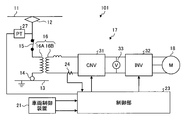
- FIG. 2 is a schematic configuration diagram of an electric system of the locomotive according to the embodiment.
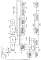
- FIG. 3 is a detailed block diagram of the control unit.
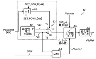
- FIG. 4 is a functional block diagram of the DC link voltage command computation unit according to the first embodiment.
- FIG. 5 is a functional block diagram of a DC link voltage command calculation unit according to the second embodiment.
- FIG. 6 is a functional block diagram of a DC link voltage command calculation unit according to the third embodiment.
- FIG. 7 is a functional block diagram of a DC link voltage command calculation unit according to the fourth embodiment.
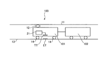
- Drawing 1 is an explanatory view of the train of the embodiment, and the overhead line state.
- the train 100 includes an electric locomotive (rail car) 101 and a passenger car (or freight car) 102 which is towed (or propelled from the rear) by the electric locomotive 101.
- the electric locomotive 101 includes a pantograph 12 to which AC power is supplied from an overhead wire (feed line) 11 and a wheel 14 grounded via a track 13.
- the electric locomotive 101 transmits and receives information such as control signals from ground equipment via the ground element ET provided on the track 13 side and the on-board child TT provided on the electric locomotive 101,
- the vehicle control device 21 controls the entire electric locomotive 101 in consideration of the acquired information.
- FIG. 2 is a schematic configuration diagram of an electric system of the locomotive according to the embodiment. As illustrated in FIG. 2, the electric locomotive 101 according to the embodiment is disconnected between the pantograph 12 to which AC power is supplied from the overhead wire 11 and the wheel 14 grounded via the line 13. The primary winding (primary coil) 16A of the transformer 15 and the transformer 16 is connected in series.
- the motor 18 is connected to the secondary winding (secondary coil) 16 B of the transformer 16 via the main power conversion device 17.
- a voltage detector (PT: Potential transformer) 27 for detecting an overhead wire voltage and outputting the detected overhead wire voltage to a control unit 23 described later is provided.
- the main power conversion device 17 includes a converter (CNV) 31, an inverter (INV) 32, and a DC voltage sensor 33.
- converter 31 converts AC power input from transformer 16 into DC power during normal operation, and converts DC power input from inverter 32 into AC power during regenerative power supply operation to convert the transformer. Supply to 16.
- inverter 32 converts DC power input from converter 31 into three-phase AC power and supplies it to motor 18, and converts regenerative power (AC power) of motor 18 to DC power.
- the data is supplied to the converter 31.
- the DC voltage sensor 33 detects a voltage (hereinafter, referred to as a DC link voltage) Vdc of DC power input / output between the converter 31 and the inverter 32.
- the circuit breaker 15 is controlled by the vehicle control device 21. Further, under the control of the vehicle control device 21, the control unit 23 controls the converter 31 and the inverter 32 which constitute the main power conversion device 17.
- the secondary winding 16B is further provided with a current sensor 24 for detecting the current flowing through the secondary winding 16B.
- FIG. 3 is a detailed block diagram of the control unit.
- Control unit 23 includes power supply voltage calculation unit 41, DC link voltage command calculation unit 42, DC link voltage control unit 43, converter current command generation unit 44, converter current control unit 45, and PWM control unit 46.
- a multiplier 47, a unit converter 48, an inverter current command generation unit 51, an inverter current control unit 52, and a PWM control unit 53 are provided.
- the power supply voltage calculation unit 41 of the control unit 23 calculates the overhead wire voltage to the voltage on the secondary winding 16B side based on the output signal of the voltage detector 27, and outputs it as the power supply voltage signal SPW (unit V).
- DC link voltage command calculation unit 42 is configured to receive motor rotation speed signal TV (evaluation value: unit km / h) input from vehicle control device 21 or an output reference signal PowerRef (evaluation value: unit kW) described later.
- a DC link voltage command signal VdcRef for controlling a DC link voltage input / output between the converter 31 and the inverter 32 is generated and output based on at least one of them and the power supply voltage signal SPW.
- the DC link voltage control unit 43 of the control unit 23 causes the DC link voltage to be a voltage corresponding to the DC link voltage command signal VdcRef based on the DC link voltage (detection signal) Vdc output from the DC voltage sensor 33.
- the DC link voltage control signal CVDC is output.
- converter current command generation unit 44 generates and outputs converter current command signal IsRef based on DC link voltage control signal CVDC.
- converter current control unit 45 outputs converter current control signal CIC based on current detection signal Is and converter current command signal IsRef output from current sensor 24 provided in secondary winding 16B.
- the unit converter 48 performs unit conversion of the multiplication result of the multiplier 47 and outputs an output reference signal PowerRef (unit kW).
- the inverter current command generation unit 51 of the control unit 23 generates and outputs the q-axis current command signal IqRef and the d-axis current command signal IdRef as inverter current command signals based on the traction force command signal TLC.
- the inverter current control unit 52 also outputs an inverter current control signal IIC based on the q-axis current command signal IqRef and the d-axis current command signal IdRef.
- the PWM control unit 53 also outputs a PWM control signal PWM2 to the inverter 32 based on the inverter current control signal IIC.
- FIG. 4 is a functional configuration block diagram of a DC link voltage command calculation unit according to a first embodiment.
- the DC link voltage command calculation unit 42 operates between the converter 31 and the inverter 32 based on the motor rotational speed signal TV (in km / h) input from the vehicle control device 21 and the power supply voltage signal SPW. It is an embodiment of the first aspect of generating a DC link voltage command signal VdcRef for controlling a DC link voltage Vdc to be input / output.
- the DC link voltage command calculation unit 42 includes a hysteresis comparator 61, a DC link voltage generation unit 62, a switch 63, a maximum value output unit 64, an upper and lower limit limiter 65, and a change rate limiter 66.
- the comparison result signal of “H” level (“1” level) is output and the output of the motor 18 corresponding to the output reference signal PowerRef falls below the low output threshold value SET_POW_L corresponding to a predetermined low output state
- the DC link voltage generation unit 62 generates and outputs the high side set value (voltage) VLH of the DC link voltage Vdc and the low side set value (voltage) VLL of the DC link voltage Vdc.
- the switch 63 has a high potential side terminal TH and a low potential side terminal TL.
- the high side setting value VLH of the DC link voltage is applied to the high potential side terminal TH, and the DC link voltage is applied to the low potential side terminal TL.
- the low set value VLL is applied, and the output is switched by the comparison result signal SW of the hysteresis comparator 61.
- the maximum value output unit 64 receives the power supply voltage signal SPW and the low-side set value (voltage) VLL, and outputs the higher one as the DC link voltage command signal VdcRef, effectively the DC link voltage Vdc. Does not fall below the value obtained by converting the overhead wire voltage to the voltage on the secondary winding 16B side.
- the upper and lower limit limiter 65 sets a DC link voltage maximum value, which is a predetermined allowable maximum value of the DC link voltage Vdc, as a limit maximum voltage, and outputs a voltage corresponding to the DC link voltage command signal VdcRef as a limit minimum voltage. Further, the change rate limiter 66 outputs the DC link voltage command signal VdcRef while limiting the change rate per unit time of the output of the upper and lower limit limiter 65 to be within a predetermined range.
- the maximum value output unit 64 is provided by setting the peak value of the voltage on the secondary winding 16B side of the transformer 16 of the overhead wire voltage to the DC link voltage Vdc. To prevent or suppress the increase in current distortion.
- the change rate limiter 66 is provided to suppress a rapid change in torque of the motor 18 by avoiding a rapid change in the DC link voltage command signal VdcRef.
- the power supply voltage calculation unit 41 of the control unit 23 calculates the overhead wire voltage to the voltage on the secondary winding 16B side based on the output signal of the voltage detector 27 and sets the DC link voltage command as the power supply voltage signal SPW (unit V). It is output to the calculation unit 42.
- the vehicle control device 21 outputs the motor rotational speed signal TV and the traction force command signal TLC to the multiplier 47, and the multiplier 47 converts the product of the motor rotational speed signal TV and the traction force command signal TLC into units. Output to the unit 48.
- the unit converter 48 performs unit conversion of the multiplication result of the multiplier 47 and outputs the result as the output reference signal PowerRef to the DC link voltage command calculation unit 42.
- the DC link voltage generation unit 62 of the DC link voltage command calculation unit 42 generates the high side set value (voltage) VLH of the DC link voltage and the low side set value (voltage) VLL of the DC link voltage and outputs the same to the switch 63 Do.
- the hysteresis comparator 61 compares the “H” level (“1” level) comparison result When the signal SW is output and the output of the motor 18 corresponding to the output reference signal PowerRef falls below the low output threshold value SET_POW_L corresponding to a predetermined low output state, the comparison result signal at the “L” level (“0” level) Output SW.
- hysteresis comparator 61 outputs comparison result signal SW at "L" level ("0" level) if it is less than high output threshold value SET_POW_H, and if it is higher than high output threshold value SET_POW_H A comparison result signal SW of H "level (" 1 "level) is output.
- the hysteresis comparator 61 When the output of the motor 18 decreases, the hysteresis comparator 61 outputs the comparison result signal SW at “H” level (“1” level) if it exceeds the low output threshold value SET_POW_L, and if it is less than the low output threshold value SET_POW_L The comparison result signal SW of L "level (" 0 "level) is output.
- the output of the motor 18 when the output of the motor 18 is increased, it is less than the high output threshold value SET_POW_H and when the output of the motor 18 is decreased, it is less than the low output threshold value SET_POW_L.
- the value (voltage) VLL will be output.
- the converter 31 and the inverter 32 are configured without affecting the operation of the electric locomotive 101 by effectively reducing the DC link voltage Vdc. It is possible to suppress the occurrence of a failure of a switching element such as an IGBT.
- Maximum value output unit 64 receives power supply voltage signal SPW and low side set value (voltage) VLL, and sets the higher one of DC link voltage command signal VdcRef as the DC link voltage reference value to the upper and lower limit limiter 65. Output to
- the upper and lower limit limiter 65 sets the DC link voltage maximum value, which is a predetermined allowable maximum value of the DC link voltage Vdc, as the maximum limit voltage, and limits the DC link voltage reference value voltage corresponding to the DC link voltage command signal VdcRef.
- the minimum voltage is output to the change rate limiter 66.
- the change rate limiter 66 outputs the DC link voltage command signal VdcRef to the DC link voltage control unit 43 while limiting the change rate per unit time of the output of the upper and lower limit limiter 65 to a predetermined range.
- the DC link voltage control unit 43 controls the DC link voltage control signal CVDC so that the DC link voltage becomes a voltage corresponding to the DC link voltage command signal VdcRef based on the DC voltage (detection signal) Vdc output from the DC voltage sensor 33.
- Converter current command signal IsRef is generated based on DC link voltage control signal CVDC and is output to converter current command generation unit 44.
- Converter current control unit 45 outputs converter current control signal CIC to PWM control unit 46 based on current detection signal Is and converter current command signal IsRef.
- the PWM control unit 46 outputs the PWM control signal PWM1 to the converter 31 based on the converter current control signal CIC.
- the inverter current command generation unit 51 generates the q-axis current command signal IqRef and the d-axis current command signal IdRef as inverter current command signals based on the traction force command signal TLC input from the vehicle control device 21 to control the inverter current. Output to the part 52.
- the inverter current control unit 52 outputs an inverter current control signal IIC to the PWM control unit 53 based on the q-axis current command signal IqRef and the d-axis current command signal IdRef.
- the PWM control unit 53 outputs the PWM control signal PWM2 to the inverter 32 based on the inverter current control signal IIC.
- the DC link voltage Vdc output by the converter 31 is effective when the output of the motor 18 is small. Have been lowered. Therefore, without affecting the operation of the electric locomotive 101, it is possible to suppress the occurrence of a failure of a switching element such as an IGBT constituting the converter 31 and the inverter 32.
- control is performed by dividing the output reference signal PowerRef as an evaluation value into two value regions, but it is also possible to configure control by dividing into three or more value regions. It is.
- FIG. 5 is a functional block diagram of a DC link voltage command calculation unit according to the second embodiment.
- the same parts as those in the first embodiment of FIG. 4 are given the same reference numerals.
- the power supply voltage calculation unit 41 of the control unit 23 calculates the overhead wire voltage to the voltage on the secondary winding 16B side based on the output signal of the voltage detector 27 and sets the DC link voltage command as the power supply voltage signal SPW (unit V). It is output to the calculation unit 42.
- the vehicle control device 21 outputs the motor rotational speed signal TV and the traction force command signal TLC to the multiplier 47, and the multiplier 47 converts the product of the motor rotational speed signal TV and the traction force command signal TLC into units. Output to the unit 48.
- the unit converter 48 performs unit conversion of the multiplication result of the multiplier 47 and outputs the result as the output reference signal PowerRef to the DC link voltage command calculation unit 42.
- the divider 71 of the DC link voltage command calculation unit 42 divides the value of the output reference signal PowerRef by the value of the maximum output PowerRef_MAX corresponding to the design maximum output power of the motor 18 to the multiplier 72. Output.
- the multiplier 72 multiplies the output of the divider 71 by the lowest voltage setting value VLLmin of the DC link voltage, and outputs the result as the high side setting value VLH1 to the high potential side terminal TH of the switch 73.
- the lowest voltage setting value VLLmin is output to the low potential side terminal TL as the low side setting value (voltage) of the DC link voltage.
- the hysteresis comparator 61 compares the “H” level (“1” level) comparison result When the signal SW is output and the output of the motor 18 corresponding to the output reference signal PowerRef falls below the low output threshold value SET_POW_L corresponding to a predetermined low output state, the comparison result signal at the “L” level (“0” level) Output SW.
- the hysteresis comparator 61 outputs the comparison result signal SW of “L” level (“0” level) when the output of the motor 18 increases and is less than the high output threshold value SET_POW_H.
- the hysteresis comparator 61 outputs the comparison result signal SW of “H” level (“1” level) when the output of the motor 18 is increased and is equal to or higher than the high output threshold value SET_POW_H.
- the hysteresis comparator 61 When the output of the motor 18 decreases, the hysteresis comparator 61 outputs the comparison result signal SW at “H” level (“1” level) if it exceeds the low output threshold value SET_POW_L, and if it is less than the low output threshold value SET_POW_L The comparison result signal SW of L "level (" 0 "level) is output.
- the minimum voltage set value VLLmin is output. It will be done.
- the converter 31 and the inverter 32 are configured without affecting the operation of the electric locomotive 101 by effectively reducing the DC link voltage Vdc. It is possible to suppress the occurrence of a failure of a switching element such as an IGBT.
- FIG. 6 is a functional block diagram of a DC link voltage command calculation unit according to a third embodiment.
- the same parts as in the first embodiment of FIG. 4 are given the same reference numerals.
- the comparison result signal of “H” level (“1” level) is output, and the rotation speed of the motor 18 corresponding to the motor rotation speed signal TV is predetermined.
- the power supply voltage calculation unit 41 of the control unit 23 calculates the overhead wire voltage to the voltage on the secondary winding 16B side based on the output signal of the voltage detector 27 and sets the DC link voltage command as the power supply voltage signal SPW (unit V). It is output to the calculation unit 42.
- the vehicle control device 21 outputs the motor rotational speed signal TV and the traction force command signal TLC to the multiplier 47, and the multiplier 47 converts the product of the motor rotational speed signal TV and the traction force command signal TLC into units. Output to the unit 48.
- the unit converter 48 performs unit conversion of the multiplication result of the multiplier 47 and outputs the result as the output reference signal PowerRef to the DC link voltage command calculation unit 42.
- the DC link voltage generation unit 62 of the DC link voltage command calculation unit 42 generates the high side set value (voltage) VLH of the DC link voltage and the low side set value (voltage) VLL of the DC link voltage and outputs the same to the switch 63 Do.
- the hysteresis comparator 61 sets the “H” level (“1” level) when the rotation speed of the motor 18 corresponding to the motor rotation speed signal TV becomes equal to or higher than the high rotation speed threshold SET_SPEED_H corresponding to the predetermined high rotation speed state. And outputs the comparison result signal SW.
- the hysteresis comparator 61 sets the “L” level (“0” level) when the rotation speed of the motor 18 corresponding to the motor rotation speed signal TV falls below the low rotation speed threshold SET_SPEED_L corresponding to the predetermined low rotation speed state. And outputs the comparison result signal SW.
- the hysteresis comparator 61A has the rotational speed of the motor 18 corresponding to the motor rotational speed signal TV equal to or higher than the high rotational speed threshold SET_SPEED_H corresponding to a predetermined high rotational speed state.
- the comparison result signal of “H” level (“1” level) is output.
- the hysteresis comparator 61A When the rotation speed of the motor 18 decreases, the hysteresis comparator 61A outputs “L when the rotation speed of the motor 18 corresponding to the motor rotation speed signal TV falls below the low rotation speed threshold value SET_SPEED_L corresponding to a predetermined low rotation speed state.
- the comparison result signal SW of “level (“ 0 ”level)” is output.
- the rotational speed of the motor 18 when the rotational speed of the motor 18 increases, the rotational speed of the motor 18 is less than the high rotational speed threshold SET_SPEED_H corresponding to the predetermined high rotational speed state, and when the rotational speed of the motor 18 decreases.
- the low rotation speed threshold value SET_SPEED_L the low setting value (voltage) VLL of the DC link voltage is output. Therefore, the rotation speed of the motor 18 is low, and the DC link voltage Vdc is sufficiently low.
- switching elements such as IGBTs constituting the converter 31 and the inverter 32 without affecting the operation of the electric locomotive 101 by effectively reducing the DC link voltage Vdc. It is possible to suppress the occurrence of
- the motor rotational speed signal TV corresponding to the evaluation value is divided into two value regions and control is performed.
- the control is divided into three or more value regions and controlled. Is also possible.
- the fourth embodiment is different from the third embodiment in that the DC link voltage generator 62 of the first embodiment sets the high-side set value VLH of the DC link voltage Vdc and the DC link voltage Vdc.
- the high side setting value VLH1 is a value proportional to the motor rotational speed signal TV, while one of the two voltages of the low side setting value VLL is output.
- FIG. 7 is a functional block diagram of a DC link voltage command calculation unit according to the fourth embodiment. In FIG. 7, the same parts as those in the third embodiment in FIG. 6 are given the same reference numerals.
- a divider 81 that outputs a value divided by the value of the rotation speed base TV_BASE corresponding to the minimum value, and a product that multiplies the output of the divider 81 by the minimum voltage setting value VLLmin of the DC link voltage and outputs it as the high side setting value VLH1
- a switch 83 for outputting the high-side set value VLH1 or the minimum voltage set value VLLmin based on the comparison result signal SW of the hysteresis comparator 61A.
- the operation of the fourth embodiment differs from the operation of the second embodiment only in the operation of the DC link voltage command computation unit 42, so the operation of the DC link voltage command computation unit 42 will be described.
- the power supply voltage calculation unit 41 of the control unit 23 calculates the overhead wire voltage to the voltage on the secondary winding 16B side based on the output signal of the voltage detector 27 and sets the DC link voltage command as the power supply voltage signal SPW (unit V). It is output to the calculation unit 42.
- the vehicle control device 21 outputs a motor rotation speed signal TV and a traction force command signal TLC corresponding to the motor rotation speed as an evaluation value to the multiplier 47, and the multiplier 47 outputs the motor rotation speed signal TV. And the product of the traction force command signal TLC to the unit converter 48.
- the unit converter 48 performs unit conversion of the multiplication result of the multiplier 47 and outputs the result as the output reference signal PowerRef to the DC link voltage command calculation unit 42.
- the divider 81 of the DC link voltage command calculation unit 42 divides the value of the output reference signal PowerRef by the value of the maximum output PowerRef_MAX corresponding to the design maximum output power of the motor 18 to the multiplier 72. Output.
- the multiplier 72 switches the value obtained by dividing the value of the motor rotational speed signal TV by the value of the rotational speed base TV_BASE corresponding to the minimum value of the motor rotational speed at which the value of the DC link voltage command signal VdcRef needs to be increased.
- the lowest voltage setting value VLLmin is output to the low potential side terminal TL as the low side setting value (voltage) of the DC link voltage.
- the hysteresis comparator 61A sets the "H” level ("1" level) when the rotation speed of the motor 18 corresponding to the motor rotation speed signal TV becomes equal to or higher than the high rotation speed threshold SET_SPEED_H corresponding to the predetermined high rotation speed state. And outputs the comparison result signal SW.
- hysteresis comparator 61A sets “L” level (“0” level) when the number of rotations of motor 18 corresponding to motor rotation speed signal TV falls below a low rotation speed threshold value SET_SPEED_L corresponding to a predetermined low rotation speed state. And outputs the comparison result signal SW.
- hysteresis comparator 61A outputs comparison result signal SW at "L" level ("0" level) if it is less than high rotational speed threshold SET_SPEED_H, and is higher than high rotational speed threshold SET_SPEED_H. If there is, the comparison result signal SW of "H" level ("1" level) is output.
- hysteresis comparator 61A When the rotational speed of motor 18 decreases, hysteresis comparator 61A outputs comparison result signal SW at “H” level (“1” level) if it is higher than low rotational speed threshold SET_SPEED_L, and is lower than low rotational speed threshold SET_SPEED_L. If there is, the comparison result signal SW of “L” level (“0” level) is output.
- the fourth embodiment when the rotational speed of the motor 18 increases, it is less than the high rotational speed threshold SET_SPEED_H, and when it is smaller than the low output threshold SET_POW_L when the rotational speed of the motor 18 decreases, the minimum voltage setting value It will output VLLmin. Therefore, when the output of the motor 18 is small, the DC link voltage Vdc is effectively lowered to affect the operation of the electric locomotive 101 without affecting the operation of the electric locomotive 101 and the IGBTs constituting the converter 31 and the inverter 32. It is possible to suppress the occurrence of a failure of the switching element of
- the DC link voltage command calculation unit 42 of each embodiment includes a control device such as a CPU, a storage device such as a ROM (Read Only Memory) or a RAM, and an external storage device such as an HDD or a CD drive.
- the program executed by the DC link voltage command calculation unit 42 is a file of an installable format or an executable format in the form of a CD-ROM, flexible disk (FD)
- the program may be provided by being recorded on a computer-readable recording medium such as a CD-R, a DVD (Digital Versatile Disk), or the like.
- the program executed by the DC link voltage command calculation unit 42 of each embodiment may be stored on a computer connected to a network such as the Internet and provided by being downloaded via the network. .
- the program executed by the DC link voltage command calculation unit 42 of each embodiment may be provided or distributed via a network such as the Internet. Further, the program of the DC link voltage command calculation unit 42 of each embodiment may be provided by being incorporated in advance in a ROM or the like.
Landscapes
- Engineering & Computer Science (AREA)
- Life Sciences & Earth Sciences (AREA)
- Sustainable Development (AREA)
- Sustainable Energy (AREA)
- Power Engineering (AREA)
- Transportation (AREA)
- Mechanical Engineering (AREA)
- Electric Propulsion And Braking For Vehicles (AREA)
Abstract
実施形態の鉄道用電力変換装置は、架線から供給された交流電力を直流リンク電力に変換して出力するコンバータと、入力された直流リンク電力を、交流電力に変換して駆動用モータに供給するインバータと、駆動用モータのパワーあるいは駆動用モータの回転速度を評価値とし、評価値に基づいて、直流リンク電力の電圧を動的に制御する制御部と、を備えるので、故障率を抑制するために過電圧、過電流、過温度等の発生を抑制することができる。
Description
本発明の実施形態は、鉄道用電力変換装置に関する。
従来、交流架線から電力を供給され、客車や貨車を牽引あるいは推進する電気機関車(交流電気車)が知られている。
このような電気機関車においては、当該電気機関車を駆動するためのモータに電力を供給するためにIGBT等のスイッチング素子を備えた主電力変換装置を備えていた。
このような電気機関車においては、当該電気機関車を駆動するためのモータに電力を供給するためにIGBT等のスイッチング素子を備えた主電力変換装置を備えていた。
ところで、主電力変換装置のスイッチング素子は、当該スイッチング素子に印加される電圧が上がると故障率が上昇するのが一般的である。
本発明は、上記に鑑みてなされたものであって、故障率を抑制するために状況に応じてスイッチング素子の印加電圧を変動させることが可能な鉄道用電力変換装置を提供することを目的としている。
実施形態の鉄道用電力変換装置は、架線から供給された交流電力を直流リンク電力に変換して出力するコンバータと、入力された直流リンク電力を、交流電力に変換して駆動用モータに供給するインバータと、駆動用モータのパワーあるいは駆動用モータの回転速度を評価値とし、評価値に基づいて、直流リンク電力の電圧を動的に制御する制御部と、を備える。
次に図面を参照して、好適な実施形態について説明する。
図1は、実施形態の列車及び架線状態の説明図である。
列車100は、電気機関車(鉄道車両)101と、電気機関車101により牽引(あるいは後方から推進)される客車(あるいは貨車)102と、を備えている。
図1は、実施形態の列車及び架線状態の説明図である。
列車100は、電気機関車(鉄道車両)101と、電気機関車101により牽引(あるいは後方から推進)される客車(あるいは貨車)102と、を備えている。
ここで、電気機関車101は、架線(き電線)11から交流電力が供給されるパンタグラフ12と、線路13を介して接地された車輪14と、を備えている。
また、電気機関車101は、線路13側に設けられた地上子ET及び当該電気機関車101に設けられた車上子TTを介して、地上設備からの制御信号等の情報の送受信を行い、取得した情報を参酌して電気機関車101全体の制御を行う車両制御装置21を備えている。
また、電気機関車101は、線路13側に設けられた地上子ET及び当該電気機関車101に設けられた車上子TTを介して、地上設備からの制御信号等の情報の送受信を行い、取得した情報を参酌して電気機関車101全体の制御を行う車両制御装置21を備えている。
図2は、実施形態にかかる機関車の電気系統の概要構成図である。
実施形態の電気機関車101は、図2に示すように、架線(き電線)11から交流電力が供給されるパンタグラフ12と、線路13を介して接地された車輪14と、の間に、遮断器15及びトランス16の一次巻線(一次コイル)16Aが直列に接続されている。
実施形態の電気機関車101は、図2に示すように、架線(き電線)11から交流電力が供給されるパンタグラフ12と、線路13を介して接地された車輪14と、の間に、遮断器15及びトランス16の一次巻線(一次コイル)16Aが直列に接続されている。
トランス16の二次巻線(二次コイル)16Bには、主電力変換装置17を介してモータ18が接続されている。
パンタグラフ12と遮断器15との間には、架線電圧を検出し、検出した架線電圧を後述する制御部23に出力するための電圧検出器(PT:Potential transformer)27が設けられている。
主電力変換装置17は、コンバータ(CNV)31と、インバータ(INV)32と、直流電圧センサ33と、を備えている。ここで、コンバータ31は、通常動作時において、トランス16から入力された交流電力を直流電力に変換するとともに、回生電力供給動作時には、インバータ32から入力された直流電力を交流電力に変換してトランス16に供給する。また、インバータ32は、通常動作時には、コンバータ31から入力された直流電力を三相交流電力に変換してモータ18に供給するとともに、モータ18の回生電力(交流電力)を直流電力に変換してコンバータ31に供給する。また、直流電圧センサ33は、コンバータ31-インバータ32間で入出力される直流電力の電圧(以下、直流リンク電圧という)Vdcを検出する。
上記構成において、遮断器15は、車両制御装置21により制御される。
また、車両制御装置21の制御下で、制御部23は、主電力変換装置17を構成しているコンバータ31及びインバータ32を制御している。
また、車両制御装置21の制御下で、制御部23は、主電力変換装置17を構成しているコンバータ31及びインバータ32を制御している。
さらに二次巻線16Bには、二次巻線16Bを流れる電流を検出するための電流センサ24が設けられている。
図3は、制御部の詳細構成ブロック図である。
制御部23は、電源電圧演算部41と、直流リンク電圧指令演算部42と、直流リンク電圧制御部43と、コンバータ電流指令生成部44と、コンバータ電流制御部45と、PWM制御部46と、乗算器47と、単位換算器48と、インバータ電流指令生成部51と、インバータ電流制御部52と、PWM制御部53と、を備えている。
制御部23は、電源電圧演算部41と、直流リンク電圧指令演算部42と、直流リンク電圧制御部43と、コンバータ電流指令生成部44と、コンバータ電流制御部45と、PWM制御部46と、乗算器47と、単位換算器48と、インバータ電流指令生成部51と、インバータ電流制御部52と、PWM制御部53と、を備えている。
ここで、制御部23の電源電圧演算部41は、電圧検出器27の出力信号に基づいて、架線電圧を二次巻線16B側の電圧に演算して電源電圧信号SPW(単位V)として出力する。また、直流リンク電圧指令演算部42は、車両制御装置21から入力されたモータ回転速度信号TV(評価値:単位km/h)、あるいは、後述する出力参照信号PowerRef(評価値:単位kW)のうち少なくともいずれか一方、及び電源電圧信号SPWに基づいてコンバータ31-インバータ32間で入出力される直流リンク電圧を制御するための直流リンク電圧指令信号VdcRefを生成し出力する。
また、制御部23の直流リンク電圧制御部43は、直流電圧センサ33が出力した直流リンク電圧(検出信号)Vdcに基づいて直流リンク電圧が直流リンク電圧指令信号VdcRefに相当する電圧となるように直流リンク電圧制御信号CVDCを出力する。また、コンバータ電流指令生成部44は、直流リンク電圧制御信号CVDCに基づいてコンバータ電流指令信号IsRefを生成し出力する。また、コンバータ電流制御部45は、二次巻線16Bに設けられた電流センサ24の出力した電流検出信号Is及びコンバータ電流指令信号IsRefに基づいてコンバータ電流制御信号CICを出力する。
さらに、制御部23はPWM制御部46は、コンバータ電流制御信号CICに基づいてPWM制御信号PWM1をコンバータに出力する。また、乗算器47は、モータ回転速度信号TV及び車両制御装置21から入力された牽引力指令信号TLC(単位F)の積(=モータ18の出力に比例)を出力する。また、単位換算器48は、乗算器47の乗算結果の単位換算を行って出力参照信号PowerRef(単位kW)を出力する。
さらにまた、制御部23のインバータ電流指令生成部51は、牽引力指令信号TLCに基づいてインバータ電流指令信号としてのq軸電流指令信号IqRef及びd軸電流指令信号IdRefを生成し出力する。また、インバータ電流制御部52は、q軸電流指令信号IqRef及びd軸電流指令信号IdRefに基づいてインバータ電流制御信号IICを出力する。また、PWM制御部53は、インバータ電流制御信号IICに基づいてPWM制御信号PWM2をインバータ32に出力する。
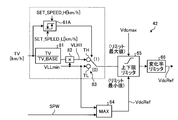
[1]第1実施形態
図4は、第1実施形態の直流リンク電圧指令演算部の機能構成ブロック図である。
本第1実施形態は、直流リンク電圧指令演算部42が、車両制御装置21から入力されたモータ回転速度信号TV(単位km/h)及び電源電圧信号SPWに基づいてコンバータ31-インバータ32間で入出力される直流リンク電圧Vdcを制御するための直流リンク電圧指令信号VdcRefを生成する第1の態様の実施形態である。
図4は、第1実施形態の直流リンク電圧指令演算部の機能構成ブロック図である。
本第1実施形態は、直流リンク電圧指令演算部42が、車両制御装置21から入力されたモータ回転速度信号TV(単位km/h)及び電源電圧信号SPWに基づいてコンバータ31-インバータ32間で入出力される直流リンク電圧Vdcを制御するための直流リンク電圧指令信号VdcRefを生成する第1の態様の実施形態である。
直流リンク電圧指令演算部42は、ヒステリシスコンパレータ61と、直流リンク電圧生成部62と、スイッチ63と、最大値出力部64と、上下限リミッタ65と、変化率リミッタ66と、を備えている。
ここで、ヒステリシスコンパレータ61は、所定のヒステリシス特性を有し、出力参照信号PowerRefに相当するモータ18の出力(=評価値:パラメータ)が所定の高出力状態に相当する高出力閾値SET_POW_H以上となった場合に“H”レベル(“1”レベル)の比較結果信号を出力し、出力参照信号PowerRefに相当するモータ18の出力が所定の低出力状態に相当する低出力閾値SET_POW_L以下となった場合に“L”レベル(“0”レベル)の比較結果信号SWを出力する。
また、直流リンク電圧生成部62は、直流リンク電圧Vdcの高側設定値(電圧)VLH及び直流リンク電圧Vdcの低側設定値(電圧)VLLを生成し出力する。
また、スイッチ63は、高電位側端子TH及び低電位側端子TLを有し、高電位側端子THに直流リンク電圧の高側設定値VLHが印加され、低電位側端子TLに直流リンク電圧の低側設定値VLLが印加されて、ヒステリシスコンパレータ61の比較結果信号SWにより出力が切り替えられる。
また、スイッチ63は、高電位側端子TH及び低電位側端子TLを有し、高電位側端子THに直流リンク電圧の高側設定値VLHが印加され、低電位側端子TLに直流リンク電圧の低側設定値VLLが印加されて、ヒステリシスコンパレータ61の比較結果信号SWにより出力が切り替えられる。
また、最大値出力部64は、電源電圧信号SPW及び低側設定値(電圧)VLLが入力され、いずれか高い方の電圧を直流リンク電圧指令信号VdcRefとして出力し、実効的に直流リンク電圧Vdcが架線電圧を二次巻線16B側の電圧に変換した値を下回らないようにする。
また、上下限リミッタ65は、直流リンク電圧Vdcの所定の許容最大値である直流リンク電圧最大値をリミット最大電圧とし、直流リンク電圧指令信号VdcRefに対応する電圧をリミット最小電圧として出力する。
また、変化率リミッタ66は、上下限リミッタ65の出力の単位時間あたりの変化率が所定範囲内となるように制限しつつ直流リンク電圧指令信号VdcRefとして出力する。
また、変化率リミッタ66は、上下限リミッタ65の出力の単位時間あたりの変化率が所定範囲内となるように制限しつつ直流リンク電圧指令信号VdcRefとして出力する。
上記構成において、最大値出力部64を設けているのは、架線電圧のトランス16の二次巻線16B側の電圧のピーク値を直流リンク電圧Vdcとすることで、単相コンバータであるコンバータ31の電流ひずみの増加を回避あるいは抑制するためである。
また、変化率リミッタ66を設けているのは、直流リンク電圧指令信号VdcRefの急変を回避することにより、モータ18のトルクの急変動を抑制するためである。
また、変化率リミッタ66を設けているのは、直流リンク電圧指令信号VdcRefの急変を回避することにより、モータ18のトルクの急変動を抑制するためである。
続いて、第1実施形態の動作を説明する。
制御部23の電源電圧演算部41は、電圧検出器27の出力信号に基づいて、架線電圧を二次巻線16B側の電圧に演算して電源電圧信号SPW(単位V)として直流リンク電圧指令演算部42に出力する。
制御部23の電源電圧演算部41は、電圧検出器27の出力信号に基づいて、架線電圧を二次巻線16B側の電圧に演算して電源電圧信号SPW(単位V)として直流リンク電圧指令演算部42に出力する。
これと並行して、車両制御装置21は、モータ回転速度信号TV及び牽引力指令信号TLCを乗算器47に出力し、乗算器47は、モータ回転速度信号TV及び牽引力指令信号TLCの積を単位換算器48に出力する。この結果、単位換算器48は、乗算器47の乗算結果の単位換算を行って出力参照信号PowerRefとして直流リンク電圧指令演算部42に出力する。
また、直流リンク電圧指令演算部42の直流リンク電圧生成部62は、直流リンク電圧の高側設定値(電圧)VLH及び直流リンク電圧の低側設定値(電圧)VLLを生成しスイッチ63に出力する。
一方、ヒステリシスコンパレータ61は、出力参照信号PowerRefに相当するモータ18の出力が所定の高出力状態に相当する高出力閾値SET_POW_H以上となった場合に“H”レベル(“1”レベル)の比較結果信号SWを出力し、出力参照信号PowerRefに相当するモータ18の出力が所定の低出力状態に相当する低出力閾値SET_POW_L以下となった場合に“L”レベル(“0”レベル)の比較結果信号SWを出力する。
すなわち、ヒステリシスコンパレータ61は、モータ18の出力増加時には、高出力閾値SET_POW_H未満であれば“L”レベル(“0”レベル)の比較結果信号SWを出力し、高出力閾値SET_POW_H以上であれば“H”レベル(“1”レベル)の比較結果信号SWを出力する。
また、ヒステリシスコンパレータ61は、モータ18の出力低下時には、低出力閾値SET_POW_L超であれば“H”レベル(“1”レベル)の比較結果信号SWを出力し、低出力閾値SET_POW_L以下であれば“L”レベル(“0”レベル)の比較結果信号SWを出力する。
したがって、本第1実施形態によれば、モータ18の出力増加時に高出力閾値SET_POW_H未満である場合及びモータ18の出力低下時に低出力閾値SET_POW_L以下である場合には、直流リンク電圧の低側設定値(電圧)VLLを出力することとなる。これらの結果、モータ18の出力が小さい場合には、実効的に直流リンク電圧Vdcを低下させることにより、電気機関車101の運行に影響を与えずに、コンバータ31及びインバータ32を構成しているIGBT等のスイッチング素子の故障発生を抑制することが可能となっている。
また、最大値出力部64は、電源電圧信号SPW及び低側設定値(電圧)VLLが入力されいずれか高い方の電圧を直流リンク電圧基準値としての直流リンク電圧指令信号VdcRefを上下限リミッタ65に出力する。
これらの結果、上下限リミッタ65は、直流リンク電圧Vdcの所定の許容最大値である直流リンク電圧最大値をリミット最大電圧とし、直流リンク電圧指令信号VdcRefに対応する直流リンク電圧基準値電圧をリミット最小電圧として変化率リミッタ66に出力する。
変化率リミッタ66は、上下限リミッタ65の出力の単位時間あたりの変化率が所定範囲内となるように制限しつつ直流リンク電圧指令信号VdcRefとして直流リンク電圧制御部43に出力する。
直流リンク電圧制御部43は、直流電圧センサ33が出力した直流電圧(検出信号)Vdcに基づいて直流リンク電圧が直流リンク電圧指令信号VdcRefに相当する電圧となるように直流リンク電圧制御信号CVDCをコンバータ電流指令生成部44に出力する。
直流リンク電圧制御信号CVDCに基づいてコンバータ電流指令信号IsRefを生成しコンバータ電流指令生成部44に出力する。
直流リンク電圧制御信号CVDCに基づいてコンバータ電流指令信号IsRefを生成しコンバータ電流指令生成部44に出力する。
コンバータ電流制御部45は、電流検出信号Is及びコンバータ電流指令信号IsRefに基づいてコンバータ電流制御信号CICをPWM制御部46に出力する。
この結果、PWM制御部46は、コンバータ電流制御信号CICに基づいてPWM制御信号PWM1をコンバータ31に出力する。
一方、インバータ電流指令生成部51は、車両制御装置21から入力された牽引力指令信号TLCに基づいてインバータ電流指令信号としてのq軸電流指令信号IqRef及びd軸電流指令信号IdRefを生成しインバータ電流制御部52に出力する。
インバータ電流制御部52は、q軸電流指令信号IqRef及びd軸電流指令信号IdRefに基づいてインバータ電流制御信号IICをPWM制御部53に出力する。
この結果、PWM制御部53は、インバータ電流制御信号IICに基づいてPWM制御信号PWM2をインバータ32に出力する。
インバータ電流制御部52は、q軸電流指令信号IqRef及びd軸電流指令信号IdRefに基づいてインバータ電流制御信号IICをPWM制御部53に出力する。
この結果、PWM制御部53は、インバータ電流制御信号IICに基づいてPWM制御信号PWM2をインバータ32に出力する。
以上の説明のように、本第1実施形態によれば、コンバータ31及びインバータ32の動作の際には、コンバータ31が出力する直流リンク電圧Vdcは、モータ18の出力が小さい場合には実効的に低下させられている。したがって、電気機関車101の運行に影響を与えずに、コンバータ31及びインバータ32を構成しているIGBT等のスイッチング素子の故障発生を抑制することができる。
以上の説明においては、評価値としての出力参照信号PowerRefを二つの値領域に区分して制御を行っていたが、3つ以上の値領域に区分して制御を行うように構成することも可能である。
以上の説明においては、評価値としての出力参照信号PowerRefを二つの値領域に区分して制御を行っていたが、3つ以上の値領域に区分して制御を行うように構成することも可能である。
[2]第2実施形態
本第2実施形態が第1実施形態と異なる点は、第1実施形態の直流リンク電圧生成部62が直流リンク電圧Vdcの高側設定値VLHを及び直流リンク電圧Vdcの低側設定値VLLの二つの電圧のいずれかを出力していたのに対し、高側設定値VLH1を出力参照信号PowerRefに比例した値としている点である。
図5は、第2実施形態の直流リンク電圧指令演算部の機能構成ブロック図である。
図5において、図4の第1実施形態と同様の部分には、同一の符号を付すものとする。
本第2実施形態が第1実施形態と異なる点は、第1実施形態の直流リンク電圧生成部62が直流リンク電圧Vdcの高側設定値VLHを及び直流リンク電圧Vdcの低側設定値VLLの二つの電圧のいずれかを出力していたのに対し、高側設定値VLH1を出力参照信号PowerRefに比例した値としている点である。
図5は、第2実施形態の直流リンク電圧指令演算部の機能構成ブロック図である。
図5において、図4の第1実施形態と同様の部分には、同一の符号を付すものとする。
直流リンク電圧指令演算部42の直流リンク電圧生成部62Aは、出力参照信号PowerRefの値(=評価値:パラメータ)をモータ18の設計上の最大出力パワーに相当する最大出力PowerRef_MAXの値で除した値を出力する除算器71と、除算器71の出力に直流リンク電圧の最低電圧設定値VLLminを乗じて高側設定値VLH1として出力する乗算器72と、ヒステリシスコンパレータ61の比較結果信号SWに基づいて高側設定値VLH1あるいは最低電圧設定値VLLminを出力するスイッチ73と、を備えている。
次に第2実施形態の要部の動作について説明する。
本第2実施形態の動作と第1実施形態の動作が異なるのは、直流リンク電圧指令演算部42の動作だけであるので、直流リンク電圧指令演算部42の動作について説明する。
本第2実施形態の動作と第1実施形態の動作が異なるのは、直流リンク電圧指令演算部42の動作だけであるので、直流リンク電圧指令演算部42の動作について説明する。
制御部23の電源電圧演算部41は、電圧検出器27の出力信号に基づいて、架線電圧を二次巻線16B側の電圧に演算して電源電圧信号SPW(単位V)として直流リンク電圧指令演算部42に出力する。
これと並行して、車両制御装置21は、モータ回転速度信号TV及び牽引力指令信号TLCを乗算器47に出力し、乗算器47は、モータ回転速度信号TV及び牽引力指令信号TLCの積を単位換算器48に出力する。この結果、単位換算器48は、乗算器47の乗算結果の単位換算を行って出力参照信号PowerRefとして直流リンク電圧指令演算部42に出力する。
これらの結果、直流リンク電圧指令演算部42の除算器71は、出力参照信号PowerRefの値をモータ18の設計上の最大出力パワーに相当する最大出力PowerRef_MAXの値で除した値を乗算器72に出力する。
乗算器72は、除算器71の出力に直流リンク電圧の最低電圧設定値VLLminを乗じて高側設定値VLH1としてスイッチ73の高電位側端子THに出力する。
一方、低電位側端子TLには、直流リンク電圧の低側設定値(電圧)として最低電圧設定値VLLminが出力される。
乗算器72は、除算器71の出力に直流リンク電圧の最低電圧設定値VLLminを乗じて高側設定値VLH1としてスイッチ73の高電位側端子THに出力する。
一方、低電位側端子TLには、直流リンク電圧の低側設定値(電圧)として最低電圧設定値VLLminが出力される。
一方、ヒステリシスコンパレータ61は、出力参照信号PowerRefに相当するモータ18の出力が所定の高出力状態に相当する高出力閾値SET_POW_H以上となった場合に“H”レベル(“1”レベル)の比較結果信号SWを出力し、出力参照信号PowerRefに相当するモータ18の出力が所定の低出力状態に相当する低出力閾値SET_POW_L以下となった場合に“L”レベル(“0”レベル)の比較結果信号SWを出力する。
すなわち、ヒステリシスコンパレータ61は、モータ18の出力増加時であって、高出力閾値SET_POW_H未満であれば“L”レベル(“0”レベル)の比較結果信号SWを出力する。また、ヒステリシスコンパレータ61は、モータ18の出力増加時であって高出力閾値SET_POW_H以上であれば“H”レベル(“1”レベル)の比較結果信号SWを出力する。
また、ヒステリシスコンパレータ61は、モータ18の出力低下時には、低出力閾値SET_POW_L超であれば“H”レベル(“1”レベル)の比較結果信号SWを出力し、低出力閾値SET_POW_L以下であれば“L”レベル(“0”レベル)の比較結果信号SWを出力する。
したがって、本第2実施形態によれば、モータ18の出力増加時に高出力閾値SET_POW_H未満である場合及びモータ18の出力低下時に低出力閾値SET_POW_L以下である場合には、最低電圧設定値VLLminを出力することとなる。
これらの結果、モータ18の出力が小さい場合には、実効的に直流リンク電圧Vdcを低下させることにより、電気機関車101の運行に影響を与えずに、コンバータ31及びインバータ32を構成しているIGBT等のスイッチング素子の故障発生を抑制することができる。
これらの結果、モータ18の出力が小さい場合には、実効的に直流リンク電圧Vdcを低下させることにより、電気機関車101の運行に影響を与えずに、コンバータ31及びインバータ32を構成しているIGBT等のスイッチング素子の故障発生を抑制することができる。
[3]第3実施形態
図6は、第3実施形態の直流リンク電圧指令演算部の機能構成ブロック図である。
図6において、図4の第1実施形態と同様の部分には、同一の符号を付すものとする。
本第3実施形態と異なる点は、ヒステリシスコンパレータ61に代えて、所定のヒステリシス特性を有し、モータ回転速度信号TVに相当するモータ18の回転速度(=評価値:パラメータ)が所定の高回転速度状態に相当する高回転速度閾値SET_SPEED_H以上となった場合に“H”レベル(“1”レベル)の比較結果信号を出力し、モータ回転速度信号TVに相当するモータ18の回転速度が所定の低回転速度状態に相当する低回転速度閾値SET_SPEED_L以下となった場合に“L”レベル(“0”レベル)の比較結果信号SWを出力するヒステリシスコンパレータ61Aを備えた点である。
図6は、第3実施形態の直流リンク電圧指令演算部の機能構成ブロック図である。
図6において、図4の第1実施形態と同様の部分には、同一の符号を付すものとする。
本第3実施形態と異なる点は、ヒステリシスコンパレータ61に代えて、所定のヒステリシス特性を有し、モータ回転速度信号TVに相当するモータ18の回転速度(=評価値:パラメータ)が所定の高回転速度状態に相当する高回転速度閾値SET_SPEED_H以上となった場合に“H”レベル(“1”レベル)の比較結果信号を出力し、モータ回転速度信号TVに相当するモータ18の回転速度が所定の低回転速度状態に相当する低回転速度閾値SET_SPEED_L以下となった場合に“L”レベル(“0”レベル)の比較結果信号SWを出力するヒステリシスコンパレータ61Aを備えた点である。
次に第3実施形態の要部の動作について説明する。
本第3実施形態の動作と第1実施形態の動作が異なるのは、直流リンク電圧指令演算部42の動作だけであるので、直流リンク電圧指令演算部42の動作について説明する。
制御部23の電源電圧演算部41は、電圧検出器27の出力信号に基づいて、架線電圧を二次巻線16B側の電圧に演算して電源電圧信号SPW(単位V)として直流リンク電圧指令演算部42に出力する。
本第3実施形態の動作と第1実施形態の動作が異なるのは、直流リンク電圧指令演算部42の動作だけであるので、直流リンク電圧指令演算部42の動作について説明する。
制御部23の電源電圧演算部41は、電圧検出器27の出力信号に基づいて、架線電圧を二次巻線16B側の電圧に演算して電源電圧信号SPW(単位V)として直流リンク電圧指令演算部42に出力する。
これと並行して、車両制御装置21は、モータ回転速度信号TV及び牽引力指令信号TLCを乗算器47に出力し、乗算器47は、モータ回転速度信号TV及び牽引力指令信号TLCの積を単位換算器48に出力する。この結果、単位換算器48は、乗算器47の乗算結果の単位換算を行って出力参照信号PowerRefとして直流リンク電圧指令演算部42に出力する。
また、直流リンク電圧指令演算部42の直流リンク電圧生成部62は、直流リンク電圧の高側設定値(電圧)VLH及び直流リンク電圧の低側設定値(電圧)VLLを生成しスイッチ63に出力する。
一方、ヒステリシスコンパレータ61は、モータ回転速度信号TVに相当するモータ18の回転数が所定の高回転数状態に相当する高回転速度閾値SET_SPEED_H以上となった場合に“H”レベル(“1”レベル)の比較結果信号SWを出力する。
また、ヒステリシスコンパレータ61は、モータ回転速度信号TVに相当するモータ18の回転数が所定の低回転数状態に相当する低回転速度閾値SET_SPEED_L以下となった場合に“L”レベル(“0”レベル)の比較結果信号SWを出力する。
すなわち、本第3実施形態においては、評価値に相当するモータ18の回転数二つの値領域(=所定の複数の値領域)に区分し、直流リンク電力の電圧を、評価値が属する値領域に対応づけた所定値に設定することとなっている。
また、ヒステリシスコンパレータ61は、モータ回転速度信号TVに相当するモータ18の回転数が所定の低回転数状態に相当する低回転速度閾値SET_SPEED_L以下となった場合に“L”レベル(“0”レベル)の比較結果信号SWを出力する。
すなわち、本第3実施形態においては、評価値に相当するモータ18の回転数二つの値領域(=所定の複数の値領域)に区分し、直流リンク電力の電圧を、評価値が属する値領域に対応づけた所定値に設定することとなっている。
より具体的には、ヒステリシスコンパレータ61Aは、モータ18の回転速度増加時には、モータ回転速度信号TVに相当するモータ18の回転速度が所定の高回転速度状態に相当する高回転速度閾値SET_SPEED_H以上となった場合に“H”レベル(“1”レベル)の比較結果信号を出力する。
またヒステリシスコンパレータ61Aは、モータ18の回転速度減少時には、モータ回転速度信号TVに相当するモータ18の回転速度が所定の低回転速度状態に相当する低回転速度閾値SET_SPEED_L以下となった場合に“L”レベル(“0”レベル)の比較結果信号SWを出力する。
したがって、本第3実施形態によれば、モータ18の回転速度増加時にモータ18の回転速度が所定の高回転速度状態に相当する高回転速度閾値SET_SPEED_H未満である場合及びモータ18の回転速度減少時に低回転速度閾値SET_SPEED_L以下である場合には、直流リンク電圧の低側設定値(電圧)VLLを出力することとなるので、モータ18の回転数が低く、直流リンク電圧Vdcが低くても十分に駆動能力が得られる場合には、実効的に直流リンク電圧Vdcを低下させることにより、電気機関車101の運行に影響を与えずに、コンバータ31及びインバータ32を構成しているIGBT等のスイッチング素子の故障発生を抑制することができる。
以上の説明においては、評価値に対応するモータ回転速度信号TVを二つの値領域に区分して制御を行っていたが、3つ以上の値領域に区分して制御を行うように構成することも可能である。
[4]第4実施形態
本第4実施形態が第3実施形態と異なる点は、第1実施形態の直流リンク電圧生成部62が直流リンク電圧Vdcの高側設定値VLHを及び直流リンク電圧Vdcの低側設定値VLLの二つの電圧のいずれかを出力していたのに対し、高側設定値VLH1をモータ回転速度信号TVに比例した値としている点である。
図7は、第4実施形態の直流リンク電圧指令演算部の機能構成ブロック図である。
図7において、図6の第3実施形態と同様の部分には、同一の符号を付すものとする。
本第4実施形態が第3実施形態と異なる点は、第1実施形態の直流リンク電圧生成部62が直流リンク電圧Vdcの高側設定値VLHを及び直流リンク電圧Vdcの低側設定値VLLの二つの電圧のいずれかを出力していたのに対し、高側設定値VLH1をモータ回転速度信号TVに比例した値としている点である。
図7は、第4実施形態の直流リンク電圧指令演算部の機能構成ブロック図である。
図7において、図6の第3実施形態と同様の部分には、同一の符号を付すものとする。
直流リンク電圧指令演算部42の直流リンク電圧生成部62Bは、モータ回転速度信号TVの値(=評価値:パラメータ)を、直流リンク電圧指令信号VdcRefの値を上昇させる必要があるモータ回転速度の最小値に相当する回転速度ベースTV_BASEの値で除した値を出力する除算器81と、除算器81の出力に直流リンク電圧の最低電圧設定値VLLminを乗じて高側設定値VLH1として出力する乗算器82と、ヒステリシスコンパレータ61Aの比較結果信号SWに基づいて高側設定値VLH1あるいは最低電圧設定値VLLminを出力するスイッチ83と、を備えている。
次に第4実施形態の要部の動作について説明する。
本第4実施形態の動作と第2実施形態の動作が異なるのは、直流リンク電圧指令演算部42の動作だけであるので、直流リンク電圧指令演算部42の動作について説明する。
本第4実施形態の動作と第2実施形態の動作が異なるのは、直流リンク電圧指令演算部42の動作だけであるので、直流リンク電圧指令演算部42の動作について説明する。
制御部23の電源電圧演算部41は、電圧検出器27の出力信号に基づいて、架線電圧を二次巻線16B側の電圧に演算して電源電圧信号SPW(単位V)として直流リンク電圧指令演算部42に出力する。
これと並行して、車両制御装置21は、評価値としてのモータ回転速度に対応するモータ回転速度信号TV及び牽引力指令信号TLCを乗算器47に出力し、乗算器47は、モータ回転速度信号TV及び牽引力指令信号TLCの積を単位換算器48に出力する。この結果、単位換算器48は、乗算器47の乗算結果の単位換算を行って出力参照信号PowerRefとして直流リンク電圧指令演算部42に出力する。
これらの結果、直流リンク電圧指令演算部42の除算器81は、出力参照信号PowerRefの値をモータ18の設計上の最大出力パワーに相当する最大出力PowerRef_MAXの値で除した値を乗算器72に出力する。
乗算器72は、モータ回転速度信号TVの値を、直流リンク電圧指令信号VdcRefの値を上昇させる必要があるモータ回転速度の最小値に相当する回転速度ベースTV_BASEの値で除した値をスイッチ83の高電位側端子THに出力する。
一方、低電位側端子TLには、直流リンク電圧の低側設定値(電圧)として最低電圧設定値VLLminが出力される。
乗算器72は、モータ回転速度信号TVの値を、直流リンク電圧指令信号VdcRefの値を上昇させる必要があるモータ回転速度の最小値に相当する回転速度ベースTV_BASEの値で除した値をスイッチ83の高電位側端子THに出力する。
一方、低電位側端子TLには、直流リンク電圧の低側設定値(電圧)として最低電圧設定値VLLminが出力される。
一方、ヒステリシスコンパレータ61Aは、モータ回転速度信号TVに相当するモータ18の回転数が所定の高回転数状態に相当する高回転速度閾値SET_SPEED_H以上となった場合に“H”レベル(“1”レベル)の比較結果信号SWを出力する。また、ヒステリシスコンパレータ61Aは、モータ回転速度信号TVに相当するモータ18の回転数が所定の低回転数状態に相当する低回転速度閾値SET_SPEED_L以下となった場合に“L”レベル(“0”レベル)の比較結果信号SWを出力する。
すなわち、ヒステリシスコンパレータ61Aは、モータ18の回転速度増加時には、高回転速度閾値SET_SPEED_H未満であれば“L”レベル(“0”レベル)の比較結果信号SWを出力し、高回転速度閾値SET_SPEED_H以上であれば“H”レベル(“1”レベル)の比較結果信号SWを出力する。
また、ヒステリシスコンパレータ61Aは、モータ18の回転速度減少時には、低回転速度閾値SET_SPEED_L超であれば“H”レベル(“1”レベル)の比較結果信号SWを出力し、低回転速度閾値SET_SPEED_L以下であれば“L”レベル(“0”レベル)の比較結果信号SWを出力する。
したがって、本第4実施形態によれば、モータ18の回転速度増加時に高回転速度閾値SET_SPEED_H未満である場合及びモータ18の回転速度減少時に低出力閾値SET_POW_L以下である場合には、最低電圧設定値VLLminを出力することとなる。したがって、モータ18の出力が小さい場合には、実効的に直流リンク電圧Vdcを低下させることにより、電気機関車101の運行に影響を与えずに、コンバータ31及びインバータ32を構成しているIGBT等のスイッチング素子の故障発生を抑制することができる。
本発明のいくつかの実施形態を説明したが、これらの実施形態は、例として提示したものであり、発明の範囲を限定することは意図していない。これら新規な実施形態は、その他の様々な形態で実施されることが可能であり、発明の要旨を逸脱しない範囲で、種々の省略、置き換え、変更を行うことができる。これら実施形態やその変形は、発明の範囲や要旨に含まれるとともに、請求の範囲に記載された発明とその均等の範囲に含まれる。
例えば、以上の説明においては、評価値をハードウェア的に構成された各演算部により演算して直流リンク電力の電圧を設定していたが、評価値を所定の関数のパラメータとして用いて、ソフトウェア的に直流リンク電力の電圧を設定するように構成することも可能である。
より詳細には、各実施形態の直流リンク電圧指令演算部42を、CPUなどの制御装置と、ROM(Read Only Memory)やRAMなどの記憶装置と、HDD、CDドライブ装置などの外部記憶装置と、を備えた通常のコンピュータを利用したハードウェア構成とし、直流リンク電圧指令演算部42で実行されるプログラムは、インストール可能な形式又は実行可能な形式のファイルでCD-ROM、フレキシブルディスク(FD)、CD-R、DVD(Digital Versatile Disk)等のコンピュータで読み取り可能な記録媒体に記録されて提供されるようにしてもよい。
また、各実施形態の直流リンク電圧指令演算部42で実行されるプログラムを、インターネット等のネットワークに接続されたコンピュータ上に格納し、ネットワーク経由でダウンロードさせることにより提供するように構成してもよい。また、各実施形態の直流リンク電圧指令演算部42で実行されるプログラムをインターネット等のネットワーク経由で提供または配布するように構成してもよい。
また、各実施形態の直流リンク電圧指令演算部42のプログラムを、ROM等に予め組み込んで提供するように構成してもよい。
例えば、以上の説明においては、評価値をハードウェア的に構成された各演算部により演算して直流リンク電力の電圧を設定していたが、評価値を所定の関数のパラメータとして用いて、ソフトウェア的に直流リンク電力の電圧を設定するように構成することも可能である。
より詳細には、各実施形態の直流リンク電圧指令演算部42を、CPUなどの制御装置と、ROM(Read Only Memory)やRAMなどの記憶装置と、HDD、CDドライブ装置などの外部記憶装置と、を備えた通常のコンピュータを利用したハードウェア構成とし、直流リンク電圧指令演算部42で実行されるプログラムは、インストール可能な形式又は実行可能な形式のファイルでCD-ROM、フレキシブルディスク(FD)、CD-R、DVD(Digital Versatile Disk)等のコンピュータで読み取り可能な記録媒体に記録されて提供されるようにしてもよい。
また、各実施形態の直流リンク電圧指令演算部42で実行されるプログラムを、インターネット等のネットワークに接続されたコンピュータ上に格納し、ネットワーク経由でダウンロードさせることにより提供するように構成してもよい。また、各実施形態の直流リンク電圧指令演算部42で実行されるプログラムをインターネット等のネットワーク経由で提供または配布するように構成してもよい。
また、各実施形態の直流リンク電圧指令演算部42のプログラムを、ROM等に予め組み込んで提供するように構成してもよい。
Claims (9)
- 架線から供給された交流電力を直流リンク電力に変換して出力するコンバータと、
入力された前記直流リンク電力を、交流電力に変換して駆動用モータに供給するインバータと、
前記駆動用モータのパワーあるいは前記駆動用モータの回転速度を評価値とし、前記評価値に基づいて、前記直流リンク電力の電圧を動的に制御する制御部と、
を備えた鉄道用電力変換装置。 - 前記制御部は、前記評価値を入力パラメータとして前記直流電力の電圧を算出し、算出された前記直流電力の電圧となるように前記制御を行う、
請求項1記載の鉄道用電力変換装置。 - 前記制御部は、前記評価値をパラメータとして所定の最大値及び所定の最小値の範囲内に制限しつつ前記直流電力の電圧を算出する、
請求項2記載の鉄道用電力変換装置。 - 前記制御部は、前記評価値を所定の複数の値領域に区分し、前記直流リンク電力の電圧を、前記評価値が属する値領域に対応づけた所定値に設定する、
請求項1乃至請求項3のいずれか一項記載の鉄道用電力変換装置。 - 前記制御部は、前記評価値に比例した値を前記直流リンク電力の電圧とする、
請求項1記載の鉄道用電力変換装置。 - 前記評価値に基づいて、前記直流リンク電力の電圧を動的に制御するための直流リンク電圧指令信号を生成する直流リンク電圧指令演算部を備え、
前記直流リンク電圧指令演算部は、前記直流リンク電力の電圧の上限電圧値及び下限電圧値を設定するために前記直流リンク電圧指令信号の上限値及び下限値を設定するための上下限リミッタを備えた、
請求項1乃至請求項5のいずれか一項記載の鉄道用電力変換装置。 - 前記架線に一次巻線が電気的に接続され、前記コンバータの交流側端子に二次巻線が電気的に接続されたトランスを備え、
前記二次巻線の電圧よりも前記直流リンク電圧の電圧を高く設定する、
請求項6記載の鉄道用電力変換装置。 - 所定の下限電圧値と、前記二次巻線の電圧と、を比較し、いずれか高い方の電圧を前記上下限リミッタにおける下限電圧として設定する最大値出力部を備えた、
請求項7記載の鉄道用電力変換装置。 - 前記直流リンク電圧の単位時間当たりの変化率を所定の変化率以下とするために、前記直流リンク電圧指令信号の変化率を制限する変化率リミッタを備えた、
請求項6乃至請求項8のいずれか一項記載の鉄道用電力変換装置。
Priority Applications (1)
| Application Number | Priority Date | Filing Date | Title |
|---|---|---|---|
| CN201680057238.5A CN108136914A (zh) | 2015-10-02 | 2016-01-20 | 铁路用电力变换装置 |
Applications Claiming Priority (2)
| Application Number | Priority Date | Filing Date | Title |
|---|---|---|---|
| JP2015-196895 | 2015-10-02 | ||
| JP2015196895A JP2017070169A (ja) | 2015-10-02 | 2015-10-02 | 鉄道用電力変換装置 |
Publications (1)
| Publication Number | Publication Date |
|---|---|
| WO2017056515A1 true WO2017056515A1 (ja) | 2017-04-06 |
Family
ID=58422942
Family Applications (1)
| Application Number | Title | Priority Date | Filing Date |
|---|---|---|---|
| PCT/JP2016/051597 Ceased WO2017056515A1 (ja) | 2015-10-02 | 2016-01-20 | 鉄道用電力変換装置 |
Country Status (3)
| Country | Link |
|---|---|
| JP (1) | JP2017070169A (ja) |
| CN (1) | CN108136914A (ja) |
| WO (1) | WO2017056515A1 (ja) |
Citations (4)
| Publication number | Priority date | Publication date | Assignee | Title |
|---|---|---|---|---|
| JP2008086082A (ja) * | 2006-09-26 | 2008-04-10 | Toshiba Corp | 永久磁石電動機の制御装置 |
| JP2010035373A (ja) * | 2008-07-30 | 2010-02-12 | Toshiba Corp | 鉄道車両駆動制御装置 |
| WO2011070609A1 (ja) * | 2009-12-08 | 2011-06-16 | 三菱電機株式会社 | 推進制御装置 |
| JP2013176230A (ja) * | 2012-02-27 | 2013-09-05 | Hitachi Ltd | 鉄道車両用駆動システム,これを備えた鉄道車両,駆動制御方法 |
Family Cites Families (1)
| Publication number | Priority date | Publication date | Assignee | Title |
|---|---|---|---|---|
| JP5398634B2 (ja) * | 2010-05-12 | 2014-01-29 | 株式会社東芝 | 交流電気車 |
-
2015
- 2015-10-02 JP JP2015196895A patent/JP2017070169A/ja active Pending
-
2016
- 2016-01-20 WO PCT/JP2016/051597 patent/WO2017056515A1/ja not_active Ceased
- 2016-01-20 CN CN201680057238.5A patent/CN108136914A/zh not_active Withdrawn
Patent Citations (4)
| Publication number | Priority date | Publication date | Assignee | Title |
|---|---|---|---|---|
| JP2008086082A (ja) * | 2006-09-26 | 2008-04-10 | Toshiba Corp | 永久磁石電動機の制御装置 |
| JP2010035373A (ja) * | 2008-07-30 | 2010-02-12 | Toshiba Corp | 鉄道車両駆動制御装置 |
| WO2011070609A1 (ja) * | 2009-12-08 | 2011-06-16 | 三菱電機株式会社 | 推進制御装置 |
| JP2013176230A (ja) * | 2012-02-27 | 2013-09-05 | Hitachi Ltd | 鉄道車両用駆動システム,これを備えた鉄道車両,駆動制御方法 |
Also Published As
| Publication number | Publication date |
|---|---|
| JP2017070169A (ja) | 2017-04-06 |
| CN108136914A (zh) | 2018-06-08 |
Similar Documents
| Publication | Publication Date | Title |
|---|---|---|
| US7723865B2 (en) | Bidirectional buck boost DC-DC converter, railway coach drive control system, and railway feeder system | |
| WO2017199661A1 (ja) | モータ駆動制御装置及び電動装置 | |
| AU2020273311B2 (en) | Current reduction system for inverters connected to a common bus | |
| JP2008312403A (ja) | 電力変換装置 | |
| CN105007023A (zh) | 电动机驱动装置 | |
| AU2009356390B2 (en) | Propulsion control device | |
| US20150120120A1 (en) | Electric drive vehicle | |
| US8803356B2 (en) | Controller for AC electric train | |
| JP2018093724A (ja) | 車両用制御装置及び鉄道車両 | |
| WO2018123917A1 (ja) | 鉄道車両用回路システム | |
| JP2017055500A (ja) | 鉄道車両の制御システム及び制御方法 | |
| WO2017064788A1 (ja) | マルチレベル電力変換装置 | |
| JP2018046714A (ja) | モータの駆動装置 | |
| JPWO2017056588A1 (ja) | 鉄道車両用電力変換装置 | |
| EP2843826A2 (en) | Method and apparatus for controlling induction motor of train | |
| WO2017056515A1 (ja) | 鉄道用電力変換装置 | |
| JP6524240B2 (ja) | 鉄道車両、車両用電力変換装置及び方法 | |
| US20190100113A1 (en) | Electric vehicle | |
| JPWO2020105080A1 (ja) | 電力変換装置および断線検出方法 | |
| JP6847697B2 (ja) | 電気車制御装置 | |
| JP6937913B2 (ja) | 鉄道車両用制御装置 | |
| JP2017153279A (ja) | 電気車制御装置および電気車システム | |
| JP7545374B2 (ja) | 電力変換器の制御装置および制御方法 | |
| JP2008104265A (ja) | 永久磁石形電動機駆動鉄道車両の制御方式 | |
| JP7460508B2 (ja) | 電力変換装置 |
Legal Events
| Date | Code | Title | Description |
|---|---|---|---|
| 121 | Ep: the epo has been informed by wipo that ep was designated in this application |
Ref document number: 16850693 Country of ref document: EP Kind code of ref document: A1 |
|
| NENP | Non-entry into the national phase |
Ref country code: DE |
|
| 122 | Ep: pct application non-entry in european phase |
Ref document number: 16850693 Country of ref document: EP Kind code of ref document: A1 |