WO2017051766A1 - ガスタービンの制御装置及び方法、ガスタービンの制御プログラム、ガスタービン - Google Patents
ガスタービンの制御装置及び方法、ガスタービンの制御プログラム、ガスタービン Download PDFInfo
- Publication number
- WO2017051766A1 WO2017051766A1 PCT/JP2016/077320 JP2016077320W WO2017051766A1 WO 2017051766 A1 WO2017051766 A1 WO 2017051766A1 JP 2016077320 W JP2016077320 W JP 2016077320W WO 2017051766 A1 WO2017051766 A1 WO 2017051766A1
- Authority
- WO
- WIPO (PCT)
- Prior art keywords
- opening
- compressor
- inlet guide
- gas turbine
- opening degree
- Prior art date
- Legal status (The legal status is an assumption and is not a legal conclusion. Google has not performed a legal analysis and makes no representation as to the accuracy of the status listed.)
- Ceased
Links
Images


Classifications
-
- F—MECHANICAL ENGINEERING; LIGHTING; HEATING; WEAPONS; BLASTING
- F02—COMBUSTION ENGINES; HOT-GAS OR COMBUSTION-PRODUCT ENGINE PLANTS
- F02C—GAS-TURBINE PLANTS; AIR INTAKES FOR JET-PROPULSION PLANTS; CONTROLLING FUEL SUPPLY IN AIR-BREATHING JET-PROPULSION PLANTS
- F02C7/00—Features, components parts, details or accessories, not provided for in, or of interest apart form groups F02C1/00 - F02C6/00; Air intakes for jet-propulsion plants
- F02C7/04—Air intakes for gas-turbine plants or jet-propulsion plants
- F02C7/057—Control or regulation
-
- F—MECHANICAL ENGINEERING; LIGHTING; HEATING; WEAPONS; BLASTING
- F02—COMBUSTION ENGINES; HOT-GAS OR COMBUSTION-PRODUCT ENGINE PLANTS
- F02C—GAS-TURBINE PLANTS; AIR INTAKES FOR JET-PROPULSION PLANTS; CONTROLLING FUEL SUPPLY IN AIR-BREATHING JET-PROPULSION PLANTS
- F02C3/00—Gas-turbine plants characterised by the use of combustion products as the working fluid
- F02C3/04—Gas-turbine plants characterised by the use of combustion products as the working fluid having a turbine driving a compressor
-
- F—MECHANICAL ENGINEERING; LIGHTING; HEATING; WEAPONS; BLASTING
- F02—COMBUSTION ENGINES; HOT-GAS OR COMBUSTION-PRODUCT ENGINE PLANTS
- F02C—GAS-TURBINE PLANTS; AIR INTAKES FOR JET-PROPULSION PLANTS; CONTROLLING FUEL SUPPLY IN AIR-BREATHING JET-PROPULSION PLANTS
- F02C7/00—Features, components parts, details or accessories, not provided for in, or of interest apart form groups F02C1/00 - F02C6/00; Air intakes for jet-propulsion plants
- F02C7/04—Air intakes for gas-turbine plants or jet-propulsion plants
- F02C7/042—Air intakes for gas-turbine plants or jet-propulsion plants having variable geometry
-
- F—MECHANICAL ENGINEERING; LIGHTING; HEATING; WEAPONS; BLASTING
- F02—COMBUSTION ENGINES; HOT-GAS OR COMBUSTION-PRODUCT ENGINE PLANTS
- F02C—GAS-TURBINE PLANTS; AIR INTAKES FOR JET-PROPULSION PLANTS; CONTROLLING FUEL SUPPLY IN AIR-BREATHING JET-PROPULSION PLANTS
- F02C7/00—Features, components parts, details or accessories, not provided for in, or of interest apart form groups F02C1/00 - F02C6/00; Air intakes for jet-propulsion plants
- F02C7/04—Air intakes for gas-turbine plants or jet-propulsion plants
- F02C7/047—Heating to prevent icing
-
- F—MECHANICAL ENGINEERING; LIGHTING; HEATING; WEAPONS; BLASTING
- F02—COMBUSTION ENGINES; HOT-GAS OR COMBUSTION-PRODUCT ENGINE PLANTS
- F02C—GAS-TURBINE PLANTS; AIR INTAKES FOR JET-PROPULSION PLANTS; CONTROLLING FUEL SUPPLY IN AIR-BREATHING JET-PROPULSION PLANTS
- F02C9/00—Controlling gas-turbine plants; Controlling fuel supply in air- breathing jet-propulsion plants
- F02C9/16—Control of working fluid flow
- F02C9/18—Control of working fluid flow by bleeding, bypassing or acting on variable working fluid interconnections between turbines or compressors or their stages
-
- F—MECHANICAL ENGINEERING; LIGHTING; HEATING; WEAPONS; BLASTING
- F02—COMBUSTION ENGINES; HOT-GAS OR COMBUSTION-PRODUCT ENGINE PLANTS
- F02C—GAS-TURBINE PLANTS; AIR INTAKES FOR JET-PROPULSION PLANTS; CONTROLLING FUEL SUPPLY IN AIR-BREATHING JET-PROPULSION PLANTS
- F02C9/00—Controlling gas-turbine plants; Controlling fuel supply in air- breathing jet-propulsion plants
- F02C9/16—Control of working fluid flow
- F02C9/20—Control of working fluid flow by throttling; by adjusting vanes
-
- F—MECHANICAL ENGINEERING; LIGHTING; HEATING; WEAPONS; BLASTING
- F05—INDEXING SCHEMES RELATING TO ENGINES OR PUMPS IN VARIOUS SUBCLASSES OF CLASSES F01-F04
- F05D—INDEXING SCHEME FOR ASPECTS RELATING TO NON-POSITIVE-DISPLACEMENT MACHINES OR ENGINES, GAS-TURBINES OR JET-PROPULSION PLANTS
- F05D2220/00—Application
- F05D2220/30—Application in turbines
- F05D2220/32—Application in turbines in gas turbines
-
- F—MECHANICAL ENGINEERING; LIGHTING; HEATING; WEAPONS; BLASTING
- F05—INDEXING SCHEMES RELATING TO ENGINES OR PUMPS IN VARIOUS SUBCLASSES OF CLASSES F01-F04
- F05D—INDEXING SCHEME FOR ASPECTS RELATING TO NON-POSITIVE-DISPLACEMENT MACHINES OR ENGINES, GAS-TURBINES OR JET-PROPULSION PLANTS
- F05D2240/00—Components
- F05D2240/35—Combustors or associated equipment
-
- F—MECHANICAL ENGINEERING; LIGHTING; HEATING; WEAPONS; BLASTING
- F05—INDEXING SCHEMES RELATING TO ENGINES OR PUMPS IN VARIOUS SUBCLASSES OF CLASSES F01-F04
- F05D—INDEXING SCHEME FOR ASPECTS RELATING TO NON-POSITIVE-DISPLACEMENT MACHINES OR ENGINES, GAS-TURBINES OR JET-PROPULSION PLANTS
- F05D2270/00—Control
- F05D2270/30—Control parameters, e.g. input parameters
- F05D2270/301—Pressure
-
- F—MECHANICAL ENGINEERING; LIGHTING; HEATING; WEAPONS; BLASTING
- F05—INDEXING SCHEMES RELATING TO ENGINES OR PUMPS IN VARIOUS SUBCLASSES OF CLASSES F01-F04
- F05D—INDEXING SCHEME FOR ASPECTS RELATING TO NON-POSITIVE-DISPLACEMENT MACHINES OR ENGINES, GAS-TURBINES OR JET-PROPULSION PLANTS
- F05D2270/00—Control
- F05D2270/30—Control parameters, e.g. input parameters
- F05D2270/303—Temperature
Definitions
- the present invention relates to a gas turbine control device and method having a compressor, a combustor, and a turbine, a gas turbine control program, and a gas turbine having a gas turbine control device.
- General gas turbine is composed of a compressor, a combustor, and a turbine.
- the air taken in from the air intake port is compressed by the compressor to become high-temperature and high-pressure compressed air.
- the combustor the fuel is supplied to the compressed air and burned, so that the high-temperature and high-pressure is burned.
- the combustion gas (working fluid) is obtained, the turbine is driven by the combustion gas, and the generator connected to the turbine is driven.
- the compressor is provided with an inlet guide vane (IGV) at an air intake, and the inlet guide vane has an opening degree based on the output (load value) of the gas turbine. Adjusted. Further, when the IGV opening is small, the compressor may generate a surging phenomenon due to a decrease in the amount of air that is sucked, and a lower limit is set for the IGV opening.
- IGV inlet guide vane
- the gas turbine is operated in a state where the outside air temperature is low, the temperature of the air flowing through the IGV may drop below the freezing point, and moisture in the air may freeze, increasing the temperature of the air flowing into the compressor.
- An anti-icing function is provided. This anti-icing function prevents icing of the air intake by guiding a part of the high-temperature pressurized air generated by the compressor to the air intake through the extraction pipe. Further, the turbine inlet temperature can be maintained by the anti-icing function to enable partial load operation of the gas turbine, and carbon monoxide (CO) in the exhaust gas can be reduced to ensure emission.
- CO carbon monoxide
- Patent Document 1 When a part of the compressed air generated by the compressor is extracted during the anti-icing operation, the compressed air for combustion in the combustor decreases, and the IGV opening needs to be corrected to the larger side. is there.
- Patent Document 1 there is one described in Patent Document 1 below.
- the operation method of the gas turbine described in Patent Document 1 calculates the opening degree of the inlet guide vanes according to the output command value for the gas turbine, and at the same time, reveals the turbine operation revealing opening calculated based on the intake air temperature and the intake air humidity. Of the degrees, a large opening is selected as the IGV opening.
- the present invention solves the above-mentioned problems, and by ensuring an optimal intake air flow rate by the compressor, it reduces carbon monoxide and guarantees emissions, while suppressing an increase in manufacturing cost due to an increase in equipment.
- An object of the present invention is to provide a gas turbine control device and method, a gas turbine control program, and a gas turbine.
- a control apparatus for a gas turbine includes a compressor, a combustor, a turbine, and an inlet that is provided at an inlet of the compressor and adjusts an amount of air flowing into the compressor.
- the second opening degree of the inlet guide vane is set from the surge limit of the compressor and the A second opening setting unit that corrects the second opening by the pressure of the compressor, and a first opening setting unit that sets the first opening of the inlet guide vane by control different from the second opening setting unit.
- An opening selection unit that selects a maximum opening of the first opening and the second opening as the opening of the inlet guide vane, and the inlet guide vane selected by the opening selection unit.
- An opening degree control unit that adjusts the opening degree of the inlet guide blade according to the opening degree; It is characterized in that.
- the first opening degree of the inlet guide vane is set by control different from the second opening degree setting unit, and the second opening degree of the inlet guide vane is set from the surge limit of the compressor and the second opening degree is set by the pressure of the compressor.
- the opening degree is corrected, and the largest opening degree among the first opening degree and the second opening degree is selected as the opening degree of the inlet guide blade, and the opening degree of the inlet guide blade is determined by the selected opening degree of the inlet guide blade. adjust.
- the first opening setting unit sets the first opening of the inlet guide vane from a factor excluding the surge limit of the compressor.
- the first opening degree setting unit can set the first opening degree of the inlet guide vanes with high accuracy based on factors excluding the surge limit of the compressor.
- the pressure of the compressor is calculated based on a casing pressure of the compressor, a casing pressure ratio calculated from an external pressure and a casing pressure, and a pressure at a predetermined position in the compressor. It is at least one of the estimated estimated cabin pressure or estimated cabin pressure ratio.
- the second opening can be set with high accuracy by using the cabin pressure, the cabin pressure ratio, the estimated cabin pressure or the estimated cabin pressure ratio as the compressor pressure.
- the second opening setting unit sets the second opening from a parameter excluding the compressor pressure, and the second opening setting unit has the casing pressure ratio. From the above, the second opening is corrected.
- the second opening degree setting unit corrects the second opening degree with the pressure of the compression ratio, an increase in the intake flow rate is suppressed more than necessary, and an optimal intake flow rate by the compressor can be secured.
- the second opening setting unit sets the first minimum opening of the inlet guide blade from a surge limit in a first state in which a predetermined extraction flow rate is ensured by the extraction flow path.
- the surge limit is set regardless of the size of the bleed flow. It is possible to appropriately set the opening degree of the inlet guide blade in consideration of the above.
- the first calculation unit calculates the first minimum opening based on a parameter excluding the pressure of the compressor
- the second calculation unit calculates the pressure of the compressor. Based on the above, the second minimum opening is calculated.
- the first minimum opening is calculated based on the parameters excluding the compressor pressure
- the second minimum opening is calculated based on the compressor pressure. Since the second minimum opening is set from the pressure and the surge limit, it is possible to suppress an increase in the intake flow rate more than necessary when the extraction flow rate is large.
- the second opening setting unit is calculated by a difference calculation unit that calculates a difference between the first minimum opening and the second minimum opening, and the difference calculation unit. And an addition unit for adding the difference to the first minimum opening calculated by the first calculation unit.
- the difference between the first minimum opening and the second minimum opening is added to the first minimum opening to set the opening of the inlet guide vanes in consideration of the surge limit of the compressor. Regardless, it is possible to appropriately set the opening degree of the inlet guide blade considering the surge limit.
- the gas turbine control device of the present invention is characterized in that a limit correction unit is provided for correcting the difference calculated by the difference calculation unit so as to fall between a preset upper limit value and lower limit value.
- the difference is prevented from becoming an abnormal value, and the opening of the inlet guide vane is abnormal.
- the change can suppress a large increase or decrease in the intake flow rate.
- the second opening setting unit includes an opening correction unit that corrects the first minimum opening and the second minimum opening with the pressure of the compressor, and the first minimum opening.
- An addition unit for adding the correction value of the opening and the correction value of the second minimum opening is provided.
- the first minimum opening when the bleed flow is small and the second minimum opening when the bleed flow is large are respectively corrected and added by the pressure of the compressor, so that the inlet guide according to the pressure of the compressor is added.
- the wing opening can be set appropriately.
- the first opening setting unit sets the minimum opening of the inlet guide vane based on the inlet temperature of the turbine.
- the opening degree control unit sets the opening side adjustment speed of the inlet guide vane opening speed faster than the closing side adjustment speed of the inlet guide vane opening degree. It is characterized by.
- the extraction flow path is characterized in that a part of the air pressurized by the compressor is extracted and led to the air intake port of the compressor.
- the gas turbine control method of the present invention includes a compressor, a combustor, a turbine, an inlet guide vane that is provided at an inlet of the compressor and adjusts an amount of air flowing into the compressor, and the compression. And a bleed passage for extracting a part of the air pressurized by the machine, wherein the second opening degree of the inlet guide blade is set from the surge limit of the compressor and the pressure of the compressor A second opening setting step for correcting the second opening; a first opening setting step for setting the first opening of the inlet guide vane by control different from the second opening setting step; and the first opening And an opening degree selecting step for selecting the maximum opening degree of the second opening degree as the opening degree of the inlet guide blade, and adjusting the opening degree of the inlet guide blade according to the selected opening degree of the inlet guide blade Opening degree control step to It is an feature.
- the pressure of the compressor is reduced, so that the occurrence of the surging phenomenon in the compressor is alleviated. Since the opening degree is corrected according to the pressure of the compressor, it is possible to suppress an increase in the intake flow rate more than necessary, and to secure an optimal intake flow rate by the compressor. Carbon oxide can be reduced to ensure emission, and an increase in manufacturing cost due to an increase in equipment can be suppressed.
- the control program for the gas turbine according to the present invention includes a compressor, a combustor, a turbine, an inlet guide vane that is provided at an inlet of the compressor and adjusts an amount of air flowing into the compressor, and the compression And a bleed passage for extracting a part of the air pressurized by the machine, wherein the second opening degree of the inlet guide blade is set from the surge limit of the compressor and the pressure of the compressor A second opening setting process for correcting the second opening; a first opening setting process for setting the first opening of the inlet guide blade by a control different from the second opening process; and the first opening.
- opening degree selection processing for selecting the maximum opening degree of the second opening degree as the opening degree of the inlet guide vane, and adjusting the opening degree of the inlet guide vane according to the selected opening degree of the inlet guide vane Opening control processing is executed by a computer. It is an feature.
- the pressure of the compressor is reduced, so that the occurrence of the surging phenomenon in the compressor is alleviated. Since the opening degree is corrected according to the pressure of the compressor, it is possible to suppress an increase in the intake flow rate more than necessary, and to secure an optimal intake flow rate by the compressor. Carbon oxide can be reduced to ensure emission, and an increase in manufacturing cost due to an increase in equipment can be suppressed.
- the gas turbine of the present invention includes a compressor, a combustor, a turbine, an inlet guide vane that is provided at an inlet of the compressor and adjusts an amount of air flowing into the compressor, and is added by the compressor.
- An extraction flow path for extracting a part of the compressed air and a control device for the gas turbine are provided.
- the pressure of the compressor is reduced, so that the occurrence of the surging phenomenon in the compressor is alleviated. Since the opening degree is corrected according to the pressure of the compressor, it is possible to suppress an increase in the intake flow rate more than necessary, and to secure an optimal intake flow rate by the compressor. Carbon oxide can be reduced to ensure emission, and an increase in manufacturing cost due to an increase in equipment can be suppressed.
- the first opening of the inlet guide vane is set by a control different from the second opening setting unit, and the compressor
- the second opening of the inlet guide vane is set from the surge limit, the second opening is corrected by the pressure of the compressor, and the maximum opening of the first opening and the second opening is set as the opening of the inlet guide vane. Since the opening degree of the inlet guide vane is adjusted according to the opening degree of the selected inlet guide vane, it is possible to prevent the intake flow rate from increasing more than necessary, and to secure the optimum intake flow rate by the compressor. As a result, carbon monoxide in the exhaust gas can be reduced to ensure emission, and an increase in manufacturing cost due to an increase in equipment can be suppressed.
- FIG. 1 is a configuration diagram illustrating a control device for a gas turbine according to the first embodiment.
- FIG. 2 is a schematic configuration diagram illustrating a specific configuration of the control device for the gas turbine according to the first embodiment.
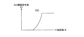
- FIG. 3 is a graph showing the first correction function.
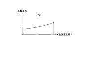
- FIG. 4 is a graph showing the second correction function.
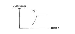
- FIG. 5 is a graph showing the third correction function.
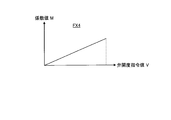
- FIG. 6 is a graph showing the fourth correction function.
- FIG. 7 is a graph showing the fifth correction function.
- FIG. 8 is a schematic configuration diagram illustrating the gas turbine according to the first embodiment.
- FIG. 9 is a schematic configuration diagram illustrating a control device for a gas turbine according to the second embodiment.
- FIG. 10 is a graph showing the sixth correction function.
- FIG. 11 is a graph for obtaining the IGV opening from the sixth correction function.
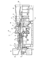
- FIG. 8 is a schematic configuration diagram illustrating the gas turbine according to the first embodiment.
- the gas turbine 10 includes a compressor 11, a combustor 12, and a turbine 13.
- the gas turbine 10 is connected to a generator (not shown) on the same axis and can generate power.
- the compressor 11 has an air intake 20 for taking in air, an inlet guide vane (IGV: Inlet Guide Vane) 22 is disposed in the compressor casing 21, and a plurality of stationary vanes 23 and moving blades 24 are provided. Arranged alternately in the front-rear direction (the axial direction of the rotor 32 to be described later), the bleed chamber 25 is provided on the outside thereof.
- the combustor 12 is combustible by supplying fuel to the compressed air compressed by the compressor 11 and igniting it.
- a plurality of stationary blades 27 and moving blades 28 are alternately disposed in a turbine casing 26 in the front-rear direction (the axial direction of a rotor 32 described later).
- An exhaust chamber 30 is disposed downstream of the turbine casing 26 via an exhaust casing 29, and the exhaust chamber 30 has an exhaust diffuser 31 that is continuous with the turbine 13.
- a rotor (rotary shaft) 32 is positioned so as to penetrate through the center of the compressor 11, the combustor 12, the turbine 13, and the exhaust chamber 30.
- the end of the rotor 32 on the compressor 11 side is rotatably supported by the bearing portion 33, while the end of the exhaust chamber 30 side is rotatably supported by the bearing portion 34.
- the rotor 32 is fixed by stacking a plurality of disks with each blade 24 mounted thereon by the compressor 11 and fixed by a plurality of disks having each blade 28 mounted by the turbine 13.
- a generator drive shaft (not shown) is connected to the end on the exhaust chamber 30 side.
- the compressor casing 21 of the compressor 11 is supported by the legs 35
- the turbine casing 26 of the turbine 13 is supported by the legs 36
- the exhaust chamber 30 is supported by the legs 37. Yes.
- the air taken in from the air intake 20 of the compressor 11 passes through the inlet guide vane 22, the plurality of stationary vanes 23 and the moving blade 24 and is compressed to become high-temperature / high-pressure compressed air.
- a predetermined fuel is supplied to the compressed air in the combustor 12 and burned.
- the high-temperature and high-pressure combustion gas that is the working fluid generated in the combustor 12 passes through the plurality of stationary blades 27 and the moving blades 28 constituting the turbine 13 to drive and rotate the rotor 32.
- the generator connected to 32 is driven.
- the combustion gas that has driven the turbine 13 is released into the atmosphere as exhaust gas.
- the compressor 11 is provided with an inlet guide vane (IGV) 22 at the air intake port 20, and the inlet guide vane 22 is used for the load value and intake air of the gas turbine 10.
- the opening degree is adjusted based on temperature or the like. Further, since the moisture in the air freezes when the temperature of the air to be taken in is low, the compressor 11 introduces a part of the compressed air of the compressor to the air intake 20 to increase the intake air temperature ( AI) function is provided. However, when the compressed air of the compressor 11 is extracted during the anti-icing operation, the cabin pressure is reduced and the occurrence of the surging phenomenon is alleviated. On the other hand, since high-temperature pressurized air is introduced into the compressor 11, the intake air temperature rises, the opening degree of the inlet guide vanes 22 increases, and an intake air flow rate that suppresses the surging phenomenon is introduced more than necessary. End up.
- the control device for the gas turbine of the first embodiment adjusts the intake air flow rate of the compressor 11 to an optimum value by setting the opening degree of the inlet guide vanes 22 to an appropriate opening degree even during anti-icing operation. Is.
- FIG. 1 is a configuration diagram illustrating a gas turbine control device according to the first embodiment
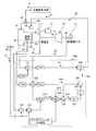
- FIG. 2 is a schematic configuration diagram illustrating a specific configuration of the gas turbine control device according to the first embodiment.
- the control device 100 of the gas turbine 10 includes a first opening setting unit 101, a second opening setting unit 102, an opening selection unit 103, and an opening control. Part 104.
- the second opening setting unit 102 includes a first calculation unit 111 and a second calculation unit 112.
- the gas turbine 10 includes a compressor 11, a combustor 12, a turbine 13, a generator 14, and a control device 100.
- the compressor 11 has a duct 41 connected to the upstream side thereof, and a temperature sensor 42 is provided inside the duct 41.
- the temperature sensor 42 detects the temperature of the air sucked into the duct 41 and outputs it as an intake air temperature value T to the control device 100.
- the compressor 11 is provided with a bleed passage 43.
- the extraction flow path 43 returns a part of the pressurized air pressurized by the compressor 11 to the duct 41 on the upstream side of the compressor 11.
- the extraction channel 43 is provided with a flow rate adjusting valve 44 in the middle.
- the opening degree of the flow rate adjusting valve 44 is controlled by a valve opening degree command value V output from the control device.
- the compressor 11 is provided with a compartment pressure sensor 45 inside the compressor compartment 21 (see FIG. 8).
- the vehicle interior pressure sensor 45 outputs the detected vehicle interior pressure as the vehicle interior pressure P to the control device 100.
- the compressor 11 is provided with the inlet guide vane (IGV: Inlet Guide Vane) 22 at the air intake 20.
- the inlet guide vane 22 is a variable vane that adjusts the amount of air (intake flow rate) sucked into the compressor 11 in accordance with the output (load) of the gas turbine 10 and is driven and controlled by the IGV drive unit 46.
- the load of the gas turbine 10 is detected by a generator output detector 47 provided in the generator 14, and the generator output detector 47 outputs the detected value to the control device 100 as a load value W.
- An atmospheric pressure sensor 48 is provided around the gas turbine.
- the atmospheric pressure sensor 48 detects the atmospheric pressure and outputs it to the control device 100 as the atmospheric pressure P 0 .
- the first opening setting unit 101 sets the first opening of the inlet guide vane 22 from factors other than the surge limit of the compressor 11.
- the first opening is the minimum opening of the inlet guide vane 22 set based on the inlet temperature of the turbine 13. That is, when the opening degree of the inlet guide vane 22 is increased, the inlet temperature of the turbine 13 increases, and when the opening degree of the inlet guide vane 22 is decreased, the inlet temperature of the turbine 13 decreases.
- the upper limit value of the inlet temperature of the turbine 13 needs to be set by the melting point of the constituent material of the turbine 13. Therefore, the first opening setting unit 101 needs to set the first opening with a certain margin so that the inlet temperature of the turbine 13 does not exceed the upper limit value.
- the second opening setting unit 102 sets the second opening of the inlet guide vane 22 from the surge limit of the compressor 11 and corrects the second opening by the pressure of the compressor 11.
- This second opening is the minimum opening of the inlet guide vane 22 set to suppress the occurrence of surging of the compressor 11.
- the second opening is an opening having a certain margin with respect to the minimum opening where surging does not occur.
- the opening selection unit 103 selects the maximum opening of the first opening and the second opening as the opening of the inlet guide vane 22.
- the opening degree control unit 104 adjusts the opening degree of the inlet guide vane 22 based on the opening degree of the inlet guide vane 22 selected by the opening degree selection unit 103.
- the first opening setting unit 101 receives the intake air temperature value T from the temperature sensor 42 and the load value W from the generator output detector 47, and the intake air temperature value T and the load value W Is set to the first IGV opening command value S1 of the inlet guide vane 22.
- the first calculation unit 111 receives the intake air temperature value T from the temperature sensor 42 and the load value W from the generator output detector 47. Based on the load value W, the second IGV opening command value S2 of the inlet guide vane 22 is set in consideration of the surge limit of the compressor 11 and the anti-icing operation. Further, the second calculator 112 corrects the second IGV opening command value S ⁇ b> 2 based on the cabin pressure ratio PR as the pressure of the compressor 11.
- the opening selection unit 103 selects the maximum IGV opening command value S as the IGV opening command value S of the inlet guide blade 22 from the first IGV opening command value S1 and the second IGV opening command value S2, and the opening The control unit 104 controls the IGV driving unit 46 based on the IGV opening command value S of the inlet guide blade 22 selected by the opening selection unit 103 to adjust the opening of the inlet guide blade 22.
- the 1st opening degree setting part 101 and the 1st calculation part 111 of the 2nd opening degree setting part 102 are 1st IGV opening degree command value S1 and 2nd IGV opening degree command value S2 from the parameter except vehicle interior pressure ratio PR.
- the second calculation unit 112 of the second opening setting unit 102 corrects the second IGV opening command value S2 from the vehicle compartment pressure ratio PR.
- the first calculation unit 111 uses the inlet guide vane based on the parameter (in this embodiment, the intake air temperature and the output) excluding the cabin pressure ratio PR from the surge limit in the first state where the bleed flow rate by the bleed flow passage 43 is small.
- the first minimum IGV opening command value S11 of 22 is set, and the second calculator 112 enters the inlet based on the vehicle compartment pressure ratio PR from the surge limit in the second state where the bleed flow rate by the bleed passage 43 in the first state is large.
- a second IGV minimum opening command value S12 for the guide vanes 22 is set.
- the first state is a state in which the extracted air is used only for cooling the high temperature portion of the turbine 13 without closing the flow rate adjusting valve 44 and operating anti-icing.
- the second state is a state in which the flow regulating valve 44 is opened to operate anti-icing and the extracted air is supplied to both the air intake port 20 of the compressor 11 and the high temperature portion of the turbine 13.
- the 2nd opening degree setting part 102 calculates the difference (DELTA) S calculated by the difference calculation part which calculates the difference (DELTA) S of 1st IGV minimum opening degree command value S11 and 2nd IGV minimum opening degree command value S12, and the difference calculation part.
- An adding unit for adding to the first IGV minimum opening command value S11 is provided.
- a limit correction unit that corrects the difference ⁇ S calculated by the difference calculation unit so that the difference ⁇ S falls between a preset upper limit value and lower limit value.
- the opening degree control unit 104 sets the opening side adjustment speed of the opening degree of the inlet guide vane 22 faster than the adjustment speed of the opening degree of the inlet guide vane 22 on the closing side.
- the control device 100 not only sets the IGV opening command value S for controlling the opening of the inlet guide vane 22, but also controls the opening of the flow rate adjusting valve 44 for the anti-icing operation.
- the valve opening command value V is set.
- the valve opening command value V is calculated based on the intake air temperature value T.
- control device 100 uses the first correction function FX1, the second correction function FX2, the third correction function FX3, the fourth correction function FX4, and the fifth correction function FX5 to use the IGV opening command of the inlet guide vane 22.
- the value S is set.
- FIG. 3 is a graph representing the first correction function
- FIG. 4 is a graph representing the second correction function
- FIG. 5 is a graph representing the third correction function
- FIG. 6 is a graph representing the fourth correction function
- FIG. These are graphs showing the fifth correction function.
- 1st correction function FX1 is a function which calculates
- FIG. For example, the function of increasing the intake flow rate of the compressor 11 by reducing the intake flow rate of the compressor 11 by reducing the IGV opening amount at a small load and increasing the IGV opening amount at the time of a heavy load is provided.
- the first correction function FX1 is basically an increase function with respect to the input load value W as shown in FIG. That is, a small first IGV opening command value S1 is output for a small load, and a large first IGV opening command value S1 is output for a large load.
- the second correction function FX2 is a function having a function of making the mass flow rate of the air sucked into the compressor 11 equal to that at the design reference temperature even when the intake air temperature of the compressor 11 is changed.
- the second correction function FX2 is basically an increase function with respect to the input intake air temperature value T as shown in FIG. That is, a small coefficient value N is output for a low intake temperature, and a large coefficient value N is output for a high intake temperature.
- the first multiplier 121 by multiplying the input load value W by the coefficient value N output from the second correction function FX2, for example, when the temperature is low, the load appears to be apparent. Decrease to close the IGV opening.
- 3rd correction function FX3 is a function which calculates
- the third correction function FX3 functions to suppress this surging phenomenon.
- the third correction function FX3 is basically an increase function with respect to the input load value W as shown in FIG. That is, a small first IGV opening command value S11 is output for a small load, and a large first IGV opening command value S11 is output for a large load.
- the fourth correction function FX4 is a function used to control the IGV opening so as to supplement the flow rate of pressurized air that is returned to the upstream side of the compressor 11 through the extraction flow path 43 during the anti-icing operation. Basically, as shown in FIG. 6, it is an increasing function with respect to the input valve opening command value V. That is, a small coefficient value M is output for a small valve opening command value V, and a large coefficient value M is output for a large valve opening command value V. As shown in FIG. 2, the second multiplier 122 multiplies the input load value W by the coefficient value M output from the fourth correction function FX4.
- the fourth correction function FX4 is an increasing function with respect to the intake air temperature value T.
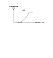
- the fifth correction function FX5 is a function for setting the IGV opening according to the passenger compartment pressure ratio PR during the anti-icing operation.
- the fifth correction function FX5 is a function for suppressing this phenomenon.
- the fifth correction function FX5 is basically an increase function with respect to the input cabin pressure ratio PR, as shown in FIG.
- the inlet guide vane 22 is adjusted to the closed side to compensate for this, so that the intake air amount does not increase due to the effect of the anti-icing operation. I have to. That is, a small IGV opening command value S12 is output for a small cabin pressure ratio PR, and a large IGV opening command value S12 is output for a large cabin pressure ratio PR.
- the temperature sensor 42 detects the temperature in the duct 41 and outputs the detected temperature to the control device 100 as an intake air temperature value T.
- the generator output detector 47 detects the output of the generator 14 and outputs it to the control device 100 as a load value W.
- the vehicle compartment pressure sensor 45 detects the pressure in the compressor vehicle compartment 21 in the compressor 11 and outputs the pressure to the control device 100 as the vehicle compartment pressure P.
- the atmospheric pressure sensor 48 detects the atmospheric pressure and outputs it to the control device 100 as the atmospheric pressure P 0 .
- the coefficient value N is obtained using the second correction function FX2 for the intake air temperature value T from the temperature sensor 42, and the first multiplier 121 receives the load value W from the generator output detector 47. Is multiplied by the coefficient value N, and the first IGV opening command value S1 is calculated by the first correction function FX1 (first opening setting unit 101). Further, the control device 100 obtains a coefficient value M for the intake air temperature value T from the temperature sensor 42 by using the fourth correction function FX4, and the second multiplier 122 receives the load from the generator output detector 47. The value W is multiplied by the coefficient value M, and the first IGV minimum opening command value S11 is calculated by the third correction function FX3 (first calculation unit 111 of the second opening setting unit 102).
- the first adder 123 adds the atmospheric pressure P 0 from the atmospheric pressure sensor 48 to the cabin pressure P from the cabin pressure sensor 45, and the first divider 124
- the vehicle interior pressure ratio PR is calculated by dividing the sum of the pressure P and the atmospheric pressure P 0 by the atmospheric pressure P 0 (the second calculation unit 112 of the second opening setting unit 102).
- a second IGV minimum opening command value S12 is obtained for the vehicle interior pressure ratio PR using the fifth correction function FX5.
- the determiner 125 selects the IGV opening command values S11 and S12 to be employed according to the anti-icing ON signal (opening selection unit 103).
- the control device 100 selects the first IGV minimum opening command value S11 when no anti-icing ON signal is input and there is no anti-icing operation (OFF). Then, the difference calculator 126 calculates a difference ⁇ S between the selected first IGV minimum opening command value S11 and the first IGV minimum opening command value S11 (difference calculation unit).
- the difference ⁇ S is 0.
- the difference calculator 126 selects the second IGV minimum opening command value S12. Then, a difference ⁇ S between the selected second IGV minimum opening command value S12 and the first IGV minimum opening command value S11 is calculated (difference calculation unit).
- the speed limiter 127 is set so that the increase side is changed quickly and the decrease side is changed slowly (slowly).
- the opening limiter 128 corrects the difference ⁇ S so that it is between the upper limit value and the lower limit value (limit correction unit).
- the second adder 129 calculates the second IGV opening command value S2 by adding the difference ⁇ S to the first IGV minimum opening command value S11.
- the high value selection unit 130 compares the first IGV opening command value S1 and the second IGV opening command value S2, and selects the higher IGV opening command value as the IGV opening command value S of the inlet guide vane 22 ( Opening selector 103).
- the first opening setting unit that sets the first IGV opening command value S1 of the inlet guide vane 22 by the control different from the second opening setting unit 102.
- a second opening setting unit 102 that sets the second IGV opening command value S2 of the inlet guide vane 22 from the surge limit of the compressor 11 and corrects the second IGV opening command value S2 by the pressure of the compressor 11;
- the opening degree selection unit 103 that selects the maximum opening degree among the first IGV opening degree command value S1 and the second IGV opening degree command value S2 as the IGV opening degree command value S of the inlet guide vane 22 and the opening degree selection unit 103
- An opening degree control unit 104 that adjusts the opening degree of the inlet guide vane 22 according to the selected IGV opening degree command value S is provided.
- the first IGV opening command value S1 of the inlet guide vane 22 is set from the control different from the second opening setting unit 102, for example, the factor excluding the surge limit of the compressor 11, and the inlet from the surge limit of the compressor 11 is set.
- the second IGV opening command value S2 of the guide blade 22 is set and corrected by the pressure of the compressor 11, and the maximum opening of the first IGV opening command value S1 and the second IGV opening command value S2 is set to the inlet guide blade 22. Is selected as the IGV opening command value S, and the opening of the inlet guide vane 22 is adjusted by the selected IGV opening command value S of the inlet guide vane 22.
- the second IGV opening command value S2 of the inlet guide vane 22 obtained from the surge limit of the compressor 11 can be corrected by the pressure of the compressor 11, and the bleed flow passage 43 allows the pressurized air of the compressor 11 to be corrected.
- the pressure of the compressor 11 decreases, so that the occurrence of a surging phenomenon in the compressor 11 is alleviated.
- the opening degree of the inlet guide vane 22 depends on the pressure of the compressor 11.
- the intake flow rate is prevented from increasing more than necessary, and the optimum intake flow rate by the compressor 11 can be secured.
- the carbon monoxide in the exhaust gas is reduced and the emission is reduced.
- an increase in manufacturing cost due to an increase in equipment can be suppressed.
- the pressure of the compressor 11 is the vehicle interior pressure of the compressor 11, the vehicle interior pressure ratio calculated from the external air pressure and the vehicle interior pressure, and a predetermined position in the compressor 11. At least one of the estimated vehicle interior pressure or the estimated vehicle interior pressure ratio estimated from the pressure is used.
- the second opening degree can be set with high accuracy by using the cabin pressure, the cabin pressure ratio, the estimated cabin pressure, or the estimated cabin pressure ratio as the pressure of the compressor 11.
- the second opening setting unit 102 sets the second IGV opening command value S2 from parameters excluding the pressure of the compressor 11, and the second opening setting unit 102
- the second IGV opening command value S2 is corrected from the cabin pressure ratio PR. Therefore, the second opening setting unit 102 corrects the second IGV opening command value S2 based on the cabin pressure ratio PR, so that an increase in the intake flow rate is suppressed more than necessary, and the optimum intake flow rate by the compressor 11 is reduced. Can be secured.
- the second opening setting unit 102 starts the first IGV minimum opening of the inlet guide vane 22 from the surge limit in the first state where a predetermined extraction flow rate is ensured by the extraction flow path 43.
- the first calculation unit 111 that sets the degree command value S11 and the second IGV minimum opening command value S12 of the inlet guide vane 22 from the surge limit of the second state in which the extraction flow rate by the extraction flow path 43 is larger than the first state.
- a second calculation unit 112 is provided. Therefore, the opening degree of the inlet guide blade 22 considering the surge limit can be set appropriately regardless of the magnitude of the bleed flow rate.
- the first calculation unit 111 calculates the first IGV minimum opening command value S11 based on the parameters excluding the cabin pressure ratio PR, and the second calculation unit 112
- the second IGV minimum opening command value S12 is calculated based on the pressure ratio PR. Therefore, when the bleed flow rate is large, the second IGV minimum opening command value S12 is set based on the cabin pressure ratio PR and the surge limit, so that it is possible to suppress the intake flow rate from increasing more than necessary when the bleed flow rate is large. it can.
- the second opening setting unit 102 calculates a difference ⁇ S between the first IGV minimum opening command value S11 and the second IGV minimum opening command value S12;
- An addition unit is provided for adding the difference calculated by the difference calculation unit to the first IGV minimum opening command value S11 calculated by the first calculation unit 111. Therefore, the opening degree of the inlet guide blade 22 considering the surge limit can be set appropriately regardless of the magnitude of the bleed flow rate.
- a limit correction unit is provided that corrects the difference ⁇ S calculated by the difference calculation unit to be between a preset upper limit value and lower limit value. Therefore, the difference ⁇ S is prevented from becoming an abnormal value, and a significant increase or decrease in the intake air flow rate can be suppressed due to an abnormal change in the opening degree of the inlet guide vane 22.
- the first opening setting unit 101 sets the first IGV opening command value S1 of the inlet guide vane 22 based on the inlet temperature of the turbine 13. Therefore, emission can be guaranteed by suppressing a decrease in exhaust gas temperature and suppressing an increase in carbon monoxide in the exhaust gas.
- the opening degree control unit 104 sets the opening side adjustment speed of the opening degree of the inlet guide blade 22 faster than the closing side adjustment speed. Therefore, when the opening degree of the inlet guide vane 22 is increased, it is opened quickly, and when the opening degree of the inlet guide vane 22 is reduced, it is closed slowly, thereby suppressing the rapid decrease in the exhaust gas temperature and reducing the emission. Can be guaranteed.
- the extraction flow path 43 enables an anti-icing operation that extracts a part of the air pressurized by the compressor 11 and guides it to the air intake port 20 of the compressor 11. . Therefore, icing of the air intake 20 is prevented.
- a second IGV opening command value S2 of the inlet guide vane 22 is set from the surge limit of the compressor 11 and corrected by the pressure of the compressor 11, and the first IGV opening command value S1 and the second IGV opening
- the opening guide step 22 selects the maximum opening of the degree command value S2 as the IGV opening command value S of the inlet guide blade 22 and the inlet guide blade 22 by the IGV opening command value S of the selected inlet guide blade 22.
- an opening degree control step for adjusting the opening degree for adjusting the opening degree.
- the pressure of the compressor 11 is reduced, so that the occurrence of the surging phenomenon in the compressor 11 is alleviated. Since the opening degree of the inlet guide vane 22 is corrected according to the pressure of the compressor 11, it is possible to suppress an increase in the intake flow rate more than necessary, and to secure an optimal intake flow rate by the compressor 11, As a result, carbon monoxide in the exhaust gas can be reduced to ensure emission, and an increase in manufacturing cost due to an increase in equipment can be suppressed.
- a first opening setting process for setting the first IGV opening command value S1 of the inlet guide vane 22 by a control different from the second opening setting process, and a surge limit of the compressor 11 A second opening setting process for setting the second IGV opening command value S2 of the inlet guide vane 22 and correcting the pressure by the pressure of the compressor 11, and among the first IGV opening command value S1 and the second IGV opening command value S2
- the opening degree of the inlet guide vane 22 is adjusted by the opening degree selecting process for selecting the maximum opening degree as the IGV opening degree command value S of the inlet guide vane 22 and the IGV opening degree command value S of the selected inlet guide vane 22.
- the computer executes the opening degree control process.
- the pressure of the compressor 11 is reduced, so that the occurrence of the surging phenomenon in the compressor 11 is alleviated. Since the opening degree of the inlet guide vane 22 is corrected according to the pressure of the compressor 11, it is possible to suppress an increase in the intake flow rate more than necessary, and to secure an optimal intake flow rate by the compressor 11, As a result, carbon monoxide in the exhaust gas can be reduced to ensure emission, and an increase in manufacturing cost due to an increase in equipment can be suppressed.
- the compressor 11, the combustor 12, the turbine 13, the inlet guide vane 22 provided at the inlet of the compressor 11 for adjusting the amount of air flowing in, and the compressor 11 are pressurized.
- a bleed passage 43 for extracting a part of the air and a control device 100 are provided. Therefore, it is possible to reduce the carbon monoxide in the exhaust gas and guarantee emission, and to suppress an increase in manufacturing cost due to an increase in equipment.
- the difference ⁇ S between the first IGV minimum opening command value S11 and the second IGV minimum opening command value S12 is calculated, and this difference ⁇ S is added to the first IGV minimum opening command value S11.
- the second IGV opening command value S2 is set, but it is not limited to this configuration.
- FIG. 9 is a schematic configuration diagram illustrating a gas turbine control device according to the second embodiment
- FIG. 10 is a graph illustrating a sixth correction function
- FIG. 11 is a graph for obtaining an IGV opening from the sixth correction function. is there.
- symbol is attached
- the control device for a gas turbine adjusts the intake air flow rate of the compressor 11 to an optimum value by setting the opening degree of the inlet guide blade 22 to an appropriate opening degree even during anti-icing operation.
- the control device 200 of the gas turbine 10 is similar to the first embodiment in that the first opening setting unit 101, the second opening setting unit 102, the opening selection unit 103, and the opening
- the second opening setting unit 102 includes a first calculation unit 111 and a second calculation unit 112 (see FIG. 1).
- the first opening setting unit 101 opens the first IGV of the inlet guide vane 22 based on the intake air temperature value T and the load value W, as in the first embodiment.
- the degree command value S1 is set.
- the first calculation unit 111 considers the surge limit of the compressor 11 by the cabin pressure ratio PR based on the intake air temperature value T and the load value W, and the second IGV opening command of the inlet guide vane 22 when the anti-icing is not operating Set the value S2.
- the second calculator 112 considers the surge limit of the compressor 11 by the cabin pressure ratio PR based on the intake air temperature value T and the load value W, and the second IGV opening command value of the inlet guide vane 22 during the anti-icing operation S2 is set.
- the 2nd opening degree setting part 102 sets 2nd IGV opening command value S2 according to the operation degree (AI degree) of anti-icing.
- the control device 200 of the second embodiment uses the first correction function FX1, the second correction function FX2, the third correction function FX3, and the fourth correction function FX4 of the first embodiment, and replaces the fifth correction function FX5.
- the sixth correction function FX6 is used to set the IGV opening command value S for the inlet guide vanes 22.
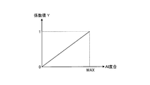
- the sixth correction function FX6 is a function for setting the IGV opening according to the passenger compartment pressure ratio PR during the anti-icing operation.
- the sixth correction function FX6 is a function for suppressing a phenomenon in which the opening degree of the inlet guide vane 22 increases and the intake flow rate increases more than necessary during the anti-icing operation.
- the operation degree of anti-icing is set according to the cabin pressure ratio PR. That is, since the cabin pressure P changes according to the opening degree of the flow rate adjusting valve 44, the relationship between the opening degree of the flow rate regulating valve 44 and the cabin pressure P is preset. When the opening degree of the flow rate adjusting valve 44 is 0 and a predetermined cabin pressure P, the anti-icing operating degree is 0.
- the anti-icing operation degree is MAX.
- the sixth correction function FX6 is basically a function of the AI degree corresponding to the input vehicle compartment pressure ratio PR, and the count value Y (with respect to the AI degree (vehicle compartment pressure ratio PR). 0 to 1.0) is output.
- the control device 200 obtains a coefficient value N for the intake air temperature value T from the temperature sensor 42 using the second correction function FX2, and the first multiplier 121 detects the generator output.
- the load value W from the device 47 is multiplied by a coefficient value N, and the first IGV opening command value S1 is calculated by the first correction function FX1 (first opening setting unit 101).
- the control device 200 obtains a coefficient value M for the intake air temperature value T from the temperature sensor 42 by using the fourth correction function FX4, and the second multiplier 122 receives the load from the generator output detector 47.
- the value W is multiplied by the coefficient value M, and the second IGV opening command reference value S11 is calculated by the third correction function FX3 (second opening setting unit 102).
- the first adder 123 adds the atmospheric pressure P 0 from the atmospheric pressure sensor 48 to the vehicle interior pressure P from the vehicle interior pressure sensor 45, and the first divider 124
- the vehicle interior pressure ratio PR is calculated by dividing the sum of the pressure P and the atmospheric pressure P 0 by the atmospheric pressure P 0 (second opening setting unit 102).
- the second multiplier 122 sets a count value Y corresponding to the anti-icing operation degree by using the cabin pressure ratio PR and the sixth correction function FX6 for the value obtained by multiplying the load value W by the coefficient value M.
- a second IGV minimum opening command value S13 is obtained using a map of the IGV opening with respect to the load value W as shown in FIG.
- the determiner 125 selects the IGV opening command values S11 and S13 to be adopted according to the anti-icing ON signal (opening selection unit 103).
- the control device 200 selects the first IGV minimum opening command value S11 when the anti-icing ON signal is not input (OFF).
- the difference calculator 126 selects the second IGV minimum opening command value S12. Then, a difference ⁇ S between the selected second IGV minimum opening command value S13 and the first IGV minimum opening command value S11 is calculated.
- the speed limiter 127 is set so that the increase side is changed quickly and the decrease side is changed slowly (slowly).
- the opening limiter 128 corrects the difference ⁇ S to be between the upper limit value and the lower limit value.
- the second adder 129 calculates the second IGV opening command value S2 by adding the difference ⁇ S to the first IGV minimum opening command value S11.
- the high value selection unit 130 compares the first IGV opening command value S1 and the second IGV opening command value S2, and selects the higher IGV opening command value as the IGV opening command value S of the inlet guide vane 22 ( Opening selector 103).
- the second opening setting unit 102 determines the first IGV minimum opening command value S11 and the second IGV minimum opening command value S13 based on the vehicle compartment pressure ratio PR.
- An opening correction unit for correcting, and an addition unit for adding the correction value of the first IGV minimum opening command value S11 and the correction value of the second IGV minimum opening command value S13 are provided.
- the first IGV minimum opening command value S11 when the bleed flow rate is small and the second IGV minimum opening command value S13 when the bleed flow rate is large are respectively corrected and added by the vehicle chamber pressure ratio PR, thereby adding the vehicle cabin pressure ratio.
- the opening degree of the inlet guide vane 22 according to PR can be set appropriately.
- the anti-icing operation degree is calculated in accordance with the vehicle compartment pressure ratio PR, and the second sensor is used to set the second IGV opening command value S2 using the sixth correction function FX6 in accordance with the anti-icing operation degree.
- the opening degree of the inlet guide vane 22 can be set appropriately.
- the cabin pressure ratio is applied as the pressure of the compressor that corrects the second opening of the inlet guide blade from the surge limit of the compressor.
- the present invention is not limited to this.
- the vehicle interior pressure may be used, and the vehicle interior pressure or the vehicle interior pressure ratio may be calculated and estimated based on the pressure at each stage, inlet, or outlet of the compressor.
- the first opening setting unit and the second opening setting unit set the IGV opening command value of the inlet guide blade using the intake air temperature value and the load value.
- the present invention is limited to this configuration. It is not something.
- the IGV opening command value of the inlet guide vane may be set based on the exhaust gas temperature.
- the anti-icing function for returning the pressurized air to the air intake port of the compressor is applied.
- the present invention is not limited to this configuration. For example, you may apply as an extraction flow path which discharges pressurized air to an exhaust duct.
- each opening degree setting unit 101, 102 is configured to adjust the opening degree of the inlet guide vane 22 based on the intake air temperature of the compressor 11, but is not limited to this configuration. Absent. For example, the opening degree of the inlet guide vane 22 may be adjusted based on the outside air temperature.
- the sixth correction function FX6 is set in accordance with the vehicle compartment pressure ratio PR.
- the present invention is not limited to this configuration.
- the sixth correction function FX6 may be set based on the opening degree of the flow rate adjustment valve 44 and the flow rate of the extraction flow path 43.
Landscapes
- Engineering & Computer Science (AREA)
- Chemical & Material Sciences (AREA)
- Combustion & Propulsion (AREA)
- Mechanical Engineering (AREA)
- General Engineering & Computer Science (AREA)
- Physics & Mathematics (AREA)
- Fluid Mechanics (AREA)
- Geometry (AREA)
- Control Of Positive-Displacement Air Blowers (AREA)
Priority Applications (4)
| Application Number | Priority Date | Filing Date | Title |
|---|---|---|---|
| DE112016004296.5T DE112016004296T5 (de) | 2015-09-24 | 2016-09-15 | Gasturbinensteuerungsvorrichtung und -verfahren, gasturbinensteuerprogramm und gasturbine |
| US15/745,185 US11421596B2 (en) | 2015-09-24 | 2016-09-15 | Gas turbine control device and method, non-transitory storage medium, and gas turbine |
| KR1020187001383A KR102022810B1 (ko) | 2015-09-24 | 2016-09-15 | 가스 터빈의 제어 장치 및 방법, 가스 터빈의 제어 프로그램을 기억하는 비일시적 기억 매체, 가스 터빈 |
| CN201680041541.6A CN107849981B (zh) | 2015-09-24 | 2016-09-15 | 燃气轮机的控制装置及方法、存储燃气轮机的控制程序的存储介质、燃气轮机 |
Applications Claiming Priority (2)
| Application Number | Priority Date | Filing Date | Title |
|---|---|---|---|
| JP2015187092A JP6590616B2 (ja) | 2015-09-24 | 2015-09-24 | ガスタービンの制御装置及び方法、ガスタービンの制御プログラム、ガスタービン |
| JP2015-187092 | 2015-09-24 |
Publications (1)
| Publication Number | Publication Date |
|---|---|
| WO2017051766A1 true WO2017051766A1 (ja) | 2017-03-30 |
Family
ID=58386652
Family Applications (1)
| Application Number | Title | Priority Date | Filing Date |
|---|---|---|---|
| PCT/JP2016/077320 Ceased WO2017051766A1 (ja) | 2015-09-24 | 2016-09-15 | ガスタービンの制御装置及び方法、ガスタービンの制御プログラム、ガスタービン |
Country Status (6)
| Country | Link |
|---|---|
| US (1) | US11421596B2 (enExample) |
| JP (1) | JP6590616B2 (enExample) |
| KR (1) | KR102022810B1 (enExample) |
| CN (1) | CN107849981B (enExample) |
| DE (1) | DE112016004296T5 (enExample) |
| WO (1) | WO2017051766A1 (enExample) |
Cited By (2)
| Publication number | Priority date | Publication date | Assignee | Title |
|---|---|---|---|---|
| US11619178B2 (en) | 2020-06-08 | 2023-04-04 | Mitsubishi Heavy Industries, Ltd. | Controller for gas turbine, control method for gas turbine, and gas turbine |
| US11913476B2 (en) | 2019-03-26 | 2024-02-27 | Mitsubishi Heavy Industries, Ltd. | Compressor system |
Families Citing this family (8)
| Publication number | Priority date | Publication date | Assignee | Title |
|---|---|---|---|---|
| JP6033391B1 (ja) * | 2015-11-24 | 2016-11-30 | 三菱日立パワーシステムズ株式会社 | ガスタービンの運転制御方法、改装方法、及びガスタービン制御装置の設定変更方法 |
| US10364754B2 (en) * | 2017-03-20 | 2019-07-30 | General Electric Company | Systems and methods for controlling overboard bleed heat of a turbine inlet filter |
| KR101898386B1 (ko) * | 2017-04-24 | 2018-09-12 | 두산중공업 주식회사 | 가스터빈 시스템 및 제어 방법 |
| JP7173897B2 (ja) * | 2019-02-28 | 2022-11-16 | 三菱重工業株式会社 | ガスタービンの運転方法およびガスタービン |
| CN111911248B (zh) * | 2020-09-10 | 2024-10-18 | 上海电气燃气轮机有限公司 | 燃气轮机燃烧稳定性调节系统及方法 |
| JP7474685B2 (ja) * | 2020-11-27 | 2024-04-25 | 三菱重工業株式会社 | 制御装置、制御方法およびプログラム |
| CN116696560B (zh) * | 2023-08-01 | 2024-01-02 | 华电电力科学研究院有限公司 | 提升燃气机组的性能优化方法、系统、装置及介质 |
| US12078103B1 (en) * | 2023-08-04 | 2024-09-03 | Rolls-Royce North American Technologies Inc. | Anti-ice mixing unit utilizing bleed air for a gas turbine engine |
Citations (4)
| Publication number | Priority date | Publication date | Assignee | Title |
|---|---|---|---|---|
| JP2001020760A (ja) * | 1999-06-25 | 2001-01-23 | General Electric Co <Ge> | 最適性能を得るための工業用ガスタービンの運転方法 |
| JP2007040171A (ja) * | 2005-08-03 | 2007-02-15 | Mitsubishi Heavy Ind Ltd | ガスタービンの入口案内翼制御装置 |
| JP2013076388A (ja) * | 2011-09-30 | 2013-04-25 | Toshiba Corp | 一軸型複合サイクル発電プラント及びその運転方法 |
| JP2013209917A (ja) * | 2012-03-30 | 2013-10-10 | Mitsubishi Heavy Ind Ltd | ガスタービンおよびその制御方法 |
Family Cites Families (9)
| Publication number | Priority date | Publication date | Assignee | Title |
|---|---|---|---|---|
| JPS5938422B2 (ja) * | 1971-10-15 | 1984-09-17 | ウエスチングハウス・エレクトリツク・コーポレーシヨン | ガスタ−ビン式パワ−・プラント |
| US4578944A (en) * | 1984-10-25 | 1986-04-01 | Westinghouse Electric Corp. | Heat recovery steam generator outlet temperature control system for a combined cycle power plant |
| JP2585324B2 (ja) * | 1987-12-09 | 1997-02-26 | 株式会社日立製作所 | ガスタービンの制御方法及びその装置 |
| JPH11200890A (ja) * | 1998-01-14 | 1999-07-27 | Toshiba Corp | ガスタービン装置の空気供給装置 |
| JP5276543B2 (ja) | 2009-07-29 | 2013-08-28 | 三菱重工業株式会社 | ガスタービンの運転方法およびガスタービン |
| JP6110110B2 (ja) | 2012-11-16 | 2017-04-05 | 三菱日立パワーシステムズ株式会社 | ガスタービン及びガスタービンの運転方法 |
| US9014945B2 (en) * | 2013-03-08 | 2015-04-21 | General Electric Company | Online enhancement for improved gas turbine performance |
| US9874109B2 (en) * | 2013-05-29 | 2018-01-23 | Siemens Energy, Inc. | System and method for controlling ice formation on gas turbine inlet guide vanes |
| US20150322861A1 (en) * | 2014-05-12 | 2015-11-12 | General Electric Company | Enhanced Turbine Cooling System Using a Blend of Compressor Bleed Air and Ambient Air |
-
2015
- 2015-09-24 JP JP2015187092A patent/JP6590616B2/ja active Active
-
2016
- 2016-09-15 CN CN201680041541.6A patent/CN107849981B/zh active Active
- 2016-09-15 KR KR1020187001383A patent/KR102022810B1/ko active Active
- 2016-09-15 US US15/745,185 patent/US11421596B2/en active Active
- 2016-09-15 WO PCT/JP2016/077320 patent/WO2017051766A1/ja not_active Ceased
- 2016-09-15 DE DE112016004296.5T patent/DE112016004296T5/de active Pending
Patent Citations (4)
| Publication number | Priority date | Publication date | Assignee | Title |
|---|---|---|---|---|
| JP2001020760A (ja) * | 1999-06-25 | 2001-01-23 | General Electric Co <Ge> | 最適性能を得るための工業用ガスタービンの運転方法 |
| JP2007040171A (ja) * | 2005-08-03 | 2007-02-15 | Mitsubishi Heavy Ind Ltd | ガスタービンの入口案内翼制御装置 |
| JP2013076388A (ja) * | 2011-09-30 | 2013-04-25 | Toshiba Corp | 一軸型複合サイクル発電プラント及びその運転方法 |
| JP2013209917A (ja) * | 2012-03-30 | 2013-10-10 | Mitsubishi Heavy Ind Ltd | ガスタービンおよびその制御方法 |
Cited By (2)
| Publication number | Priority date | Publication date | Assignee | Title |
|---|---|---|---|---|
| US11913476B2 (en) | 2019-03-26 | 2024-02-27 | Mitsubishi Heavy Industries, Ltd. | Compressor system |
| US11619178B2 (en) | 2020-06-08 | 2023-04-04 | Mitsubishi Heavy Industries, Ltd. | Controller for gas turbine, control method for gas turbine, and gas turbine |
Also Published As
| Publication number | Publication date |
|---|---|
| KR20180017190A (ko) | 2018-02-20 |
| US11421596B2 (en) | 2022-08-23 |
| DE112016004296T5 (de) | 2018-06-21 |
| JP6590616B2 (ja) | 2019-10-16 |
| KR102022810B1 (ko) | 2019-09-18 |
| CN107849981B (zh) | 2019-09-03 |
| CN107849981A (zh) | 2018-03-27 |
| US20180209341A1 (en) | 2018-07-26 |
| JP2017061879A (ja) | 2017-03-30 |
Similar Documents
| Publication | Publication Date | Title |
|---|---|---|
| JP6590616B2 (ja) | ガスタービンの制御装置及び方法、ガスタービンの制御プログラム、ガスタービン | |
| US7762084B2 (en) | System and method for controlling the working line position in a gas turbine engine compressor | |
| JP5552002B2 (ja) | サージマージン制御 | |
| US10247109B2 (en) | 2-shaft gas turbine, and the control method of opening degree of inlet guide vane of the gas turbine | |
| JP6223847B2 (ja) | ガスタービンの制御装置、ガスタービン、及びガスタービンの制御方法 | |
| JP6335720B2 (ja) | 制御装置、システム及び制御方法 | |
| JP6222993B2 (ja) | 2軸式ガスタービン | |
| CA2845182C (en) | System and method for engine transient power response | |
| US10711705B2 (en) | Operation control method and upgrade method for gas turbine, and setting change method for gas turbine control system | |
| JP2018009459A (ja) | ガスタービン及びガスタービンの運転方法 | |
| US10323570B2 (en) | Two-shaft gas turbine, and control system and control method of the gas turbine | |
| JP3730275B2 (ja) | ガスタービンの可変案内翼制御装置 | |
| JP4796015B2 (ja) | ガスタービンの運転制御装置および運転制御方法 | |
| US10858996B2 (en) | Gas turbine startup method and device | |
| JP5843515B2 (ja) | ガスタービン、ガスタービン制御装置、および発電システム | |
| JP2012077662A (ja) | ガスタービンの制御装置、ガスタービン、及びガスタービンの制御方法 | |
| JP6801968B2 (ja) | ガスタービンの制御装置および制御方法、並びにガスタービン | |
| JP6267084B2 (ja) | 制御装置、システム及び制御方法 |
Legal Events
| Date | Code | Title | Description |
|---|---|---|---|
| 121 | Ep: the epo has been informed by wipo that ep was designated in this application |
Ref document number: 16848554 Country of ref document: EP Kind code of ref document: A1 |
|
| ENP | Entry into the national phase |
Ref document number: 20187001383 Country of ref document: KR Kind code of ref document: A |
|
| WWE | Wipo information: entry into national phase |
Ref document number: 15745185 Country of ref document: US |
|
| WWE | Wipo information: entry into national phase |
Ref document number: 112016004296 Country of ref document: DE |
|
| 122 | Ep: pct application non-entry in european phase |
Ref document number: 16848554 Country of ref document: EP Kind code of ref document: A1 |