WO2017051652A1 - 噴射制御装置 - Google Patents
噴射制御装置 Download PDFInfo
- Publication number
- WO2017051652A1 WO2017051652A1 PCT/JP2016/074730 JP2016074730W WO2017051652A1 WO 2017051652 A1 WO2017051652 A1 WO 2017051652A1 JP 2016074730 W JP2016074730 W JP 2016074730W WO 2017051652 A1 WO2017051652 A1 WO 2017051652A1
- Authority
- WO
- WIPO (PCT)
- Prior art keywords
- fuel injection
- movable core
- control device
- valve
- injection control
- Prior art date
- Legal status (The legal status is an assumption and is not a legal conclusion. Google has not performed a legal analysis and makes no representation as to the accuracy of the status listed.)
- Ceased
Links
Images





Classifications
-
- F—MECHANICAL ENGINEERING; LIGHTING; HEATING; WEAPONS; BLASTING
- F02—COMBUSTION ENGINES; HOT-GAS OR COMBUSTION-PRODUCT ENGINE PLANTS
- F02D—CONTROLLING COMBUSTION ENGINES
- F02D41/00—Electrical control of supply of combustible mixture or its constituents
- F02D41/20—Output circuits, e.g. for controlling currents in command coils
-
- F—MECHANICAL ENGINEERING; LIGHTING; HEATING; WEAPONS; BLASTING
- F02—COMBUSTION ENGINES; HOT-GAS OR COMBUSTION-PRODUCT ENGINE PLANTS
- F02D—CONTROLLING COMBUSTION ENGINES
- F02D41/00—Electrical control of supply of combustible mixture or its constituents
- F02D41/30—Controlling fuel injection
- F02D41/32—Controlling fuel injection of the low pressure type
- F02D41/34—Controlling fuel injection of the low pressure type with means for controlling injection timing or duration
-
- F—MECHANICAL ENGINEERING; LIGHTING; HEATING; WEAPONS; BLASTING
- F02—COMBUSTION ENGINES; HOT-GAS OR COMBUSTION-PRODUCT ENGINE PLANTS
- F02D—CONTROLLING COMBUSTION ENGINES
- F02D41/00—Electrical control of supply of combustible mixture or its constituents
- F02D41/30—Controlling fuel injection
- F02D41/32—Controlling fuel injection of the low pressure type
- F02D41/36—Controlling fuel injection of the low pressure type with means for controlling distribution
-
- F—MECHANICAL ENGINEERING; LIGHTING; HEATING; WEAPONS; BLASTING
- F02—COMBUSTION ENGINES; HOT-GAS OR COMBUSTION-PRODUCT ENGINE PLANTS
- F02D—CONTROLLING COMBUSTION ENGINES
- F02D41/00—Electrical control of supply of combustible mixture or its constituents
- F02D41/30—Controlling fuel injection
- F02D41/38—Controlling fuel injection of the high pressure type
- F02D41/40—Controlling fuel injection of the high pressure type with means for controlling injection timing or duration
-
- F—MECHANICAL ENGINEERING; LIGHTING; HEATING; WEAPONS; BLASTING
- F02—COMBUSTION ENGINES; HOT-GAS OR COMBUSTION-PRODUCT ENGINE PLANTS
- F02D—CONTROLLING COMBUSTION ENGINES
- F02D45/00—Electrical control not provided for in groups F02D41/00 - F02D43/00
-
- F—MECHANICAL ENGINEERING; LIGHTING; HEATING; WEAPONS; BLASTING
- F02—COMBUSTION ENGINES; HOT-GAS OR COMBUSTION-PRODUCT ENGINE PLANTS
- F02M—SUPPLYING COMBUSTION ENGINES IN GENERAL WITH COMBUSTIBLE MIXTURES OR CONSTITUENTS THEREOF
- F02M51/00—Fuel-injection apparatus characterised by being operated electrically
-
- F—MECHANICAL ENGINEERING; LIGHTING; HEATING; WEAPONS; BLASTING
- F02—COMBUSTION ENGINES; HOT-GAS OR COMBUSTION-PRODUCT ENGINE PLANTS
- F02M—SUPPLYING COMBUSTION ENGINES IN GENERAL WITH COMBUSTIBLE MIXTURES OR CONSTITUENTS THEREOF
- F02M51/00—Fuel-injection apparatus characterised by being operated electrically
- F02M51/06—Injectors peculiar thereto with means directly operating the valve needle
-
- F—MECHANICAL ENGINEERING; LIGHTING; HEATING; WEAPONS; BLASTING
- F02—COMBUSTION ENGINES; HOT-GAS OR COMBUSTION-PRODUCT ENGINE PLANTS
- F02M—SUPPLYING COMBUSTION ENGINES IN GENERAL WITH COMBUSTIBLE MIXTURES OR CONSTITUENTS THEREOF
- F02M51/00—Fuel-injection apparatus characterised by being operated electrically
- F02M51/06—Injectors peculiar thereto with means directly operating the valve needle
- F02M51/061—Injectors peculiar thereto with means directly operating the valve needle using electromagnetic operating means
-
- F—MECHANICAL ENGINEERING; LIGHTING; HEATING; WEAPONS; BLASTING
- F02—COMBUSTION ENGINES; HOT-GAS OR COMBUSTION-PRODUCT ENGINE PLANTS
- F02M—SUPPLYING COMBUSTION ENGINES IN GENERAL WITH COMBUSTIBLE MIXTURES OR CONSTITUENTS THEREOF
- F02M51/00—Fuel-injection apparatus characterised by being operated electrically
- F02M51/06—Injectors peculiar thereto with means directly operating the valve needle
- F02M51/061—Injectors peculiar thereto with means directly operating the valve needle using electromagnetic operating means
- F02M51/0625—Injectors peculiar thereto with means directly operating the valve needle using electromagnetic operating means characterised by arrangement of mobile armatures
- F02M51/0664—Injectors peculiar thereto with means directly operating the valve needle using electromagnetic operating means characterised by arrangement of mobile armatures having a cylindrically or partly cylindrically shaped armature, e.g. entering the winding; having a plate-shaped or undulated armature entering the winding
- F02M51/0671—Injectors peculiar thereto with means directly operating the valve needle using electromagnetic operating means characterised by arrangement of mobile armatures having a cylindrically or partly cylindrically shaped armature, e.g. entering the winding; having a plate-shaped or undulated armature entering the winding the armature having an elongated valve body attached thereto
- F02M51/0675—Injectors peculiar thereto with means directly operating the valve needle using electromagnetic operating means characterised by arrangement of mobile armatures having a cylindrically or partly cylindrically shaped armature, e.g. entering the winding; having a plate-shaped or undulated armature entering the winding the armature having an elongated valve body attached thereto the valve body having cylindrical guiding or metering portions, e.g. with fuel passages
-
- F—MECHANICAL ENGINEERING; LIGHTING; HEATING; WEAPONS; BLASTING
- F02—COMBUSTION ENGINES; HOT-GAS OR COMBUSTION-PRODUCT ENGINE PLANTS
- F02M—SUPPLYING COMBUSTION ENGINES IN GENERAL WITH COMBUSTIBLE MIXTURES OR CONSTITUENTS THEREOF
- F02M61/00—Fuel-injectors not provided for in groups F02M39/00 - F02M57/00 or F02M67/00
- F02M61/04—Fuel-injectors not provided for in groups F02M39/00 - F02M57/00 or F02M67/00 having valves, e.g. having a plurality of valves in series
- F02M61/10—Other injectors with elongated valve bodies, i.e. of needle-valve type
-
- F—MECHANICAL ENGINEERING; LIGHTING; HEATING; WEAPONS; BLASTING
- F02—COMBUSTION ENGINES; HOT-GAS OR COMBUSTION-PRODUCT ENGINE PLANTS
- F02D—CONTROLLING COMBUSTION ENGINES
- F02D41/00—Electrical control of supply of combustible mixture or its constituents
- F02D41/02—Circuit arrangements for generating control signals
- F02D41/14—Introducing closed-loop corrections
- F02D41/1401—Introducing closed-loop corrections characterised by the control or regulation method
- F02D2041/1433—Introducing closed-loop corrections characterised by the control or regulation method using a model or simulation of the system
-
- F—MECHANICAL ENGINEERING; LIGHTING; HEATING; WEAPONS; BLASTING
- F02—COMBUSTION ENGINES; HOT-GAS OR COMBUSTION-PRODUCT ENGINE PLANTS
- F02D—CONTROLLING COMBUSTION ENGINES
- F02D41/00—Electrical control of supply of combustible mixture or its constituents
- F02D41/20—Output circuits, e.g. for controlling currents in command coils
- F02D2041/202—Output circuits, e.g. for controlling currents in command coils characterised by the control of the circuit
- F02D2041/2055—Output circuits, e.g. for controlling currents in command coils characterised by the control of the circuit with means for determining actual opening or closing time
-
- F—MECHANICAL ENGINEERING; LIGHTING; HEATING; WEAPONS; BLASTING
- F02—COMBUSTION ENGINES; HOT-GAS OR COMBUSTION-PRODUCT ENGINE PLANTS
- F02D—CONTROLLING COMBUSTION ENGINES
- F02D41/00—Electrical control of supply of combustible mixture or its constituents
- F02D41/20—Output circuits, e.g. for controlling currents in command coils
- F02D2041/202—Output circuits, e.g. for controlling currents in command coils characterised by the control of the circuit
- F02D2041/2058—Output circuits, e.g. for controlling currents in command coils characterised by the control of the circuit using information of the actual current value
-
- F—MECHANICAL ENGINEERING; LIGHTING; HEATING; WEAPONS; BLASTING
- F02—COMBUSTION ENGINES; HOT-GAS OR COMBUSTION-PRODUCT ENGINE PLANTS
- F02D—CONTROLLING COMBUSTION ENGINES
- F02D2200/00—Input parameters for engine control
- F02D2200/02—Input parameters for engine control the parameters being related to the engine
- F02D2200/06—Fuel or fuel supply system parameters
- F02D2200/0618—Actual fuel injection timing or delay, e.g. determined from fuel pressure drop
-
- F—MECHANICAL ENGINEERING; LIGHTING; HEATING; WEAPONS; BLASTING
- F16—ENGINEERING ELEMENTS AND UNITS; GENERAL MEASURES FOR PRODUCING AND MAINTAINING EFFECTIVE FUNCTIONING OF MACHINES OR INSTALLATIONS; THERMAL INSULATION IN GENERAL
- F16K—VALVES; TAPS; COCKS; ACTUATING-FLOATS; DEVICES FOR VENTING OR AERATING
- F16K31/00—Actuating devices; Operating means; Releasing devices
- F16K31/02—Actuating devices; Operating means; Releasing devices electric; magnetic
- F16K31/06—Actuating devices; Operating means; Releasing devices electric; magnetic using a magnet, e.g. diaphragm valves, cutting off by means of a liquid
- F16K31/0603—Multiple-way valves
- F16K31/0624—Lift valves
- F16K31/0627—Lift valves with movable valve member positioned between seats
-
- Y—GENERAL TAGGING OF NEW TECHNOLOGICAL DEVELOPMENTS; GENERAL TAGGING OF CROSS-SECTIONAL TECHNOLOGIES SPANNING OVER SEVERAL SECTIONS OF THE IPC; TECHNICAL SUBJECTS COVERED BY FORMER USPC CROSS-REFERENCE ART COLLECTIONS [XRACs] AND DIGESTS
- Y02—TECHNOLOGIES OR APPLICATIONS FOR MITIGATION OR ADAPTATION AGAINST CLIMATE CHANGE
- Y02T—CLIMATE CHANGE MITIGATION TECHNOLOGIES RELATED TO TRANSPORTATION
- Y02T10/00—Road transport of goods or passengers
- Y02T10/10—Internal combustion engine [ICE] based vehicles
- Y02T10/40—Engine management systems
Definitions
- the present disclosure relates to an injection control device that controls a fuel injection valve driven by electric power.
- the internal combustion engine is provided with a fuel injection valve for injecting fuel for each cylinder.
- a fuel injection valve for injecting fuel for each cylinder.
- the fuel injection valve one having a solenoid and a movable core is common.
- the fuel injection valve is switched between opening and closing when the internal valve body moves integrally with the movable core.
- the injection control device controls the fuel injection valve so that the fuel injection amount of the fuel injection valve (that is, the amount of fuel injected between the opening and closing of the fuel injection valve) matches the target value. .
- the fuel injection valve opening time is adjusted by adjusting the length of time for supplying the drive current to the fuel injection valve, the magnitude of the drive current, etc., and the fuel injection amount matches the target value
- the fuel injection amount of each fuel injection valve may vary due to individual differences or deterioration of the fuel injection valves, ambient temperature, and the like. For this reason, it is necessary to adjust the length of time for supplying the driving current, and to reduce the deviation of the fuel injection amount of each fuel injection valve. In order to control the actual fuel injection amount, it is necessary to detect the start and end of the movement of the valve body in the opening operation of the fuel injection valve.
- the start of movement of the valve element is detected based on a change in the drive current supplied to the fuel injection valve. Specifically, first, when the movable core moves together with the valve body, the inductance changes, so that the drive current changes.
- the control device described in Patent Document 1 below differentiates this driving current with respect to time and detects the start of movement of the movable core based on the differentiated value.
- ⁇ Noise may occur in the drive current supplied to the fuel injection valve due to various factors. For this reason, in the case of using a value obtained by differentiating the driving current with respect to time as in the control device described in Patent Document 1, there is a possibility that the influence of noise is greatly affected. As a result, it has been difficult to accurately detect the state of the movable core of the fuel injection valve.
- An object of the present disclosure is to provide an injection control device that is capable of accurately detecting the state of a movable core even when applied to a fuel injection valve that is not easily affected by noise and has a small inductance change.
- the injection control device controls a fuel injection valve that is driven by electric power.
- the injection control device includes a current detection unit that detects a driving current supplied to the solenoid of the fuel injection valve, and a theoretical model of the driving current in a state where the movable core that is moved by the electromagnetic force generated by the solenoid is stationary.
- An identification unit for identification and a state detection unit for detecting the state of the movable core are provided.
- the state detection unit detects the state of the movable core based on the deviation between the driving current detected by the current detection unit and the theoretical model.
- the theoretical model of the drive current is a model of the drive current when the movable core is stationary.
- the state of the movable core is detected based on the deviation between the actual driving current detected by the current detection unit and the theoretical model. Therefore, it is possible to make it less susceptible to noise generated in the driving current, compared to the case where the state of the movable core is detected based on the value obtained by differentiating the driving current with respect to time. Furthermore, even when the injection control device according to the present disclosure is applied to a fuel injection valve having a small change in inductance, it is possible to accurately detect the state of the movable core.
- FIG. 1 is a schematic diagram illustrating a configuration of an injection control device according to an embodiment and a vehicle equipped with the injection control device.
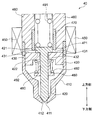
- FIG. 2 is a schematic diagram showing a closed state of the fuel injection valve of FIG.
- FIG. 3 is a schematic diagram showing the opened state of the fuel injection valve of FIG.
- FIG. 4 is a functional block diagram showing the injection control device of FIG.
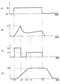
- FIG. 5 is a graph showing changes in the driving current supplied to the fuel injection valve of FIG.
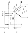
- FIG. 6 is a diagram for explaining the timing at which the movable core finishes moving in the valve opening operation
- FIG. 7 is a diagram for explaining the timing at which the movable core starts moving in the valve opening operation.
- FIG. 8 is a view for explaining the adjustment of the closing of the fuel injection valve.
- the injection control apparatus 100 will be described with reference to FIG.
- the injection control device 100 is mounted on a vehicle GC including the internal combustion engine 10.
- the injection control device 100 is a device that controls the fuel injection valve 40 provided in the internal combustion engine 10.
- the vehicle GC includes an internal combustion engine 10, an intake pipe 20, and an exhaust pipe 30.
- the internal combustion engine 10 is, for example, a reciprocating engine that uses gasoline as fuel.
- the internal combustion engine 10 has a plurality of cylinders. Each cylinder is supplied with liquid fuel and generates torque by repeatedly performing the intake stroke, the compression stroke, the combustion stroke, and the exhaust stroke. The torque is output via a crankshaft (not shown) included in the internal combustion engine 10 and used for traveling of the vehicle GC. Since the configuration of each cylinder is substantially the same, only a single cylinder is shown as the internal combustion engine 10 in FIG.
- the coolant temperature sensor 11 is a sensor for detecting the temperature of coolant circulated between a radiator (not shown) and the internal combustion engine 10.
- the knock sensor 12 is a sensor for detecting knocking that is abnormal combustion occurring inside the cylinder of the internal combustion engine 10.
- the crank angle sensor 13 is a sensor for detecting the rotation angle of the crankshaft provided in the cylinder. Each sensor generates a signal corresponding to the detected value and transmits it to the outside.
- the internal combustion engine 10 is provided with a plurality of fuel injection valves 40.
- the fuel injection valve 40 is also referred to as an injector, and is an electromagnetic valve for injecting fuel into each cylinder of the internal combustion engine 10.
- the fuel injection valve 40 is supplied with fuel pressurized by a fuel pump (not shown). When the fuel injection valve 40 is opened, the fuel injected from the tip is supplied into the cylinder while being mixed with air.
- the injection control device 100 adjusts the timing and amount of fuel supplied to the internal combustion engine 10 by controlling the opening / closing operation of the fuel injection valve 40.
- the intake pipe 20 is a pipe for supplying air to the internal combustion engine 10.
- the intake pipe 20 is provided with an air cleaner 21, an air flow meter 22, a throttle valve 23, and a surge tank 25 in order from the upstream side.
- An internal combustion engine 10 is connected to the downstream end of the intake pipe 20.
- the air cleaner 21 is a filter for removing foreign substances in the air.
- the air cleaner 21 removes foreign matter from the air supplied to the internal combustion engine 10 from the outside via the intake pipe 20.
- the air flow meter 22 is a flow meter for detecting the air flow rate.
- the air flow meter 22 detects the flow rate of air that flows through the intake pipe 20 and is supplied to the internal combustion engine 10.
- the air flow meter 22 generates a signal corresponding to the detected air flow rate and transmits the signal to the outside.
- the throttle valve 23 is a valve for adjusting the flow rate.
- an occupant of the vehicle GC operates an accelerator pedal (not shown)
- the opening degree of the throttle valve 23 is adjusted according to the operation amount.
- the throttle valve 23 is provided with an opening sensor 24.
- the opening sensor 24 detects the opening of the throttle valve 23, generates a signal corresponding to the opening, and transmits the signal to the outside.
- the surge tank 25 is a container formed in the middle of the intake pipe 20.
- the intake pipe 20 branches into a plurality on the downstream side of the surge tank 25.
- the branched portion of the intake pipe 20 is connected to each cylinder of the internal combustion engine 10.
- the internal volume of the surge tank 25 is larger than that of other parts of the intake pipe 20. By forming such a surge tank 25 in the intake pipe 20, even if a pressure fluctuation occurs in one cylinder, it can be prevented from affecting other cylinders.
- the surge tank 25 is provided with a pressure sensor 26.
- the pressure sensor 26 detects the pressure inside the intake pipe 20, generates a signal corresponding to the pressure, and transmits the signal to the outside.
- the exhaust pipe 30 is a pipe for discharging the gas generated in the combustion stroke in each cylinder of the internal combustion engine 10 to the outside.
- the upstream end of the exhaust pipe 30 is connected to the internal combustion engine 10.
- a catalytic converter 31 for purifying gas is provided in the middle of the exhaust pipe 30.
- An air-fuel ratio sensor 32 is provided in a portion of the exhaust pipe 30 upstream of the catalytic converter 31.
- the air-fuel ratio sensor 32 is a sensor for detecting the oxygen concentration of the gas flowing inside the exhaust pipe 30.
- the air-fuel ratio sensor 32 generates a signal corresponding to the detected oxygen concentration and transmits it to the outside.
- the injection control device 100 is configured so that the fuel injection amount of the fuel injection valve 40 (that is, from the opening of the fuel injection valve 40) based on the detection result of the air-fuel ratio sensor 32 or the like so that the combustion in the internal combustion engine 10 is performed at the stoichiometric air-fuel ratio. The amount of fuel injected until the valve is closed is controlled.
- FIG. 2 shows the internal structure of the fuel injection valve 40 in the closed state.
- FIG. 3 shows the internal structure of the fuel injection valve 40 in the valve open state.
- a valve body 420, a movable core 430 and the like are accommodated in a case 410 formed as a cylindrical container.
- An injection port 411 that is a fuel outlet is formed at the tip of the case 410.
- a valve seat 412 is formed on the inner wall surface of the case 410 and around the injection port 411.
- the valve body 420 is disposed in a state of being movable along the axial direction that is the longitudinal direction of the case 410. As shown in FIG. 2, when the valve body 420 is positioned on the lowermost side, the lower end of the valve body 420 comes into contact with the valve seat 412 and the injection port 411 is closed. ing. In this case, fuel is not injected from the injection port 411. When the movable core 430 moves upward and the valve body 420 also moves upward along with this, the lower end of the valve body 420 is separated from the valve seat 412. As a result, fuel is injected from the injection port 411. The greater the distance at which the valve body 420 is separated from the valve seat 412, the greater the flow rate of fuel injected from the injection port 411 per unit time. In other words, the opening degree of the fuel injection valve 40 increases as the valve body 420 moves upward.
- the entire valve body 420 has a substantially cylindrical shape.
- the valve body 420 is disposed so as to be inserted through a through hole 432 formed in the center of the movable core 430.
- an enlarged diameter portion 421 having a larger diameter than other portions is formed.
- a lower surface 422 that is an end surface on the lower side of the enlarged diameter portion 421 is in contact with an upper surface 431 that is an upper end surface of the movable core 430.
- a cylindrical body 480 is fixed to a part of the side surface of the valve body 420 below the movable core 430.
- the lower part of the cylindrical body 480 has a shape protruding outward.
- a spring 492 is disposed between the portion and the movable core 430. Since the spring 492 is disposed in a compressed state, the movable core 430 receives an upward force from the spring 492. Thereby, the valve body 420 that contacts the upper surface 431 of the movable core 430 on the lower surface 422 also receives an upward force.
- the movable core 430 is a member formed of a magnetic material such as ferritic stainless steel.
- the movable core 430 has a substantially cylindrical shape.
- the through hole 432 is formed in the center of the movable core 430.
- the valve body 420 is inserted through the through hole 432.
- the outer diameter of the movable core 430 is substantially equal to the inner diameter of the case 410.
- the movable core 430 is disposed so as to be movable in the longitudinal direction of the case 410.
- a spring 491 is disposed above the enlarged diameter portion 421 of the valve body 420.
- the spring 491 is arranged in a compressed state. Therefore, the valve body 420 receives a downward force from the spring 491.
- a fixed core 460 is disposed above the movable core 430.
- the fixed core 460 is a substantially cylindrical member formed of a magnetic material such as ferritic stainless steel.
- the fixed core 460 is fixed to the case 410.
- a gap is formed between the fixed core 460 and the movable core 430.
- a bush 470 is fixed on the inner peripheral side of the fixed core 460.
- the bush 470 has a substantially cylindrical shape.
- a part of the enlarged diameter portion 421 of the valve body 420 is disposed inside the bush 470.
- a lower end surface 471 which is an end surface on the lower side of the bush 470 is located further below the end portion on the lower side of the fixed core 460. As shown in FIG. 2, when the fuel injection valve 40 is closed, the lower end surface 471 of the bush 470 and the upper surface 431 of the movable core 430 are separated from each other.
- a solenoid 450 is disposed on the outer peripheral side of the fixed core 460.
- the injection control device 100 supplies electric power released by a battery (not shown) to the solenoid 450.
- the current supplied to operate the fuel injection valve 40 is referred to as “driving current”.
- driving current the current supplied to operate the fuel injection valve 40
- a magnetic circuit is formed in the movable core 430, the fixed core 460, and the case 410. Thereby, an electromagnetic force is generated between the movable core 430 and the fixed core 460, and the movable core 430 receives an upward force.
- the fuel injection valve 40 When the driving current is not supplied to the fuel injection valve 40, the fuel injection valve 40 is in the closed state shown in FIG.
- the supply of the driving current is started to open the fuel injection valve 40, the electromagnetic force acting on the movable core 430 gradually increases. If the resultant force of the upward force and the electromagnetic force received by the movable core 430 from the spring 492 becomes larger than the downward force that the movable core 430 receives from the spring 491 via the valve body 420, the movable core 430 moves upward. Start.
- valve opening operation the operation of the fuel injection valve 40 at the time of transition from the valve closing state shown in FIG. 2 to the valve opening state shown in FIG. 3 is referred to as “valve opening operation”.
- the upper surface 431 of the movable core 430 is in contact with the lower end surface 471 of the bush 470.
- the opening of the fuel injection valve 40 is maximized, so that the flow rate of fuel injected from the injection port 411 per unit time is also maximized.
- the injection control device 100 will be described with reference to FIG. Part or all of the injection control device 100 is configured by an analog circuit or a digital processor. In any case, in order to fulfill the function of outputting a control signal based on the received signal, the injection control device 100 includes a functional control block.
- FIG. 4 shows the injection control device 100 as a functional control block diagram.
- the software module incorporated in the analog circuit or digital processor constituting the injection control apparatus 100 does not necessarily have to be divided as in the control block shown in FIG. That is, the actual analog circuit or module may be configured to function as a plurality of control blocks shown in FIG. 4 or may be further subdivided.
- a person skilled in the art can appropriately change the actual configuration inside the injection control device 100 as long as the processing described later can be executed.
- the injection control device 100 is electrically connected to the coolant temperature sensor 11, the knock sensor 12, the crank angle sensor 13, the air flow meter 22, the opening sensor 24, the pressure sensor 26, and the air-fuel ratio sensor 32.
- the injection control device 100 performs a predetermined calculation based on signals received from the coolant temperature sensor 11, the crank angle sensor 13, the air flow meter 22, the opening sensor 24, the pressure sensor 26, and the air-fuel ratio sensor 32, thereby cooling the coolant.
- the temperature of water, the rotational speed of the internal combustion engine 10, the flow rate of air supplied to the internal combustion engine 10, the opening degree of the throttle valve 23, the pressure of air supplied to the internal combustion engine 10, and the air-fuel ratio in the internal combustion engine 10 are acquired.
- the injection control device 100 detects knocking occurring inside the cylinder of the internal combustion engine 10 by performing a predetermined calculation based on a signal received from the knock sensor 12.
- the injection control device 100 is also electrically connected to the throttle valve 23 and the fuel injection valve 40.
- the injection control device 100 transmits control signals to the throttle valve 23 and the fuel injection valve 40 to control their operations.
- electrically connected is not limited to the form of being connected to each other by a signal line, and the form of being able to communicate with each other wirelessly can be included in the meaning.
- the injection control device 100 includes a current detection unit 110, a voltage detection unit 120, an identification unit 130, a state detection unit 140, an end timing adjustment unit 150, a start timing adjustment unit 160, and a valve closing adjustment unit 170.
- the current detection unit 110 is a part that detects the drive current that actually flows through the fuel injection valve 40.
- the current detection unit 110 acquires the waveform of the drive current by detecting the drive current that changes with time.
- the voltage detector 120 is a part that detects a voltage applied to the solenoid 450 in order to operate the fuel injection valve 40.
- the voltage applied to operate the fuel injection valve 40 is referred to as “driving voltage”.
- the voltage detector 120 acquires the waveform by detecting the driving voltage that changes with time.
- the identification unit 130 is a part that identifies the theoretical model of the driving current flowing through the fuel injection valve 40.
- the theoretical model models a driving current in a state where the movable core 430 of the fuel injection valve 40 shown in FIGS. 2 and 3 is stationary. That is, the theoretical model does not take into account the change in impedance accompanying the movement of the movable core 430.
- the state detector 140 is a part that detects the state of the movable core 430 of the fuel injection valve 40. Specifically, the state detection unit 140 detects that the movement of the movable core 430 has started or that the movement of the movable core 430 has ended in the opening operation of the fuel injection valve 40.
- the end timing adjustment unit 150 is a part that adjusts the timing at which the movement of the movable core 430 ends in the valve opening operation of the fuel injection valve 40.
- the timing at which the movement of the movable core 430 ends in the valve opening operation of the fuel injection valve 40 is also referred to as “end timing”.
- the start timing adjustment unit 160 is a part that adjusts the timing at which the movable core 430 starts moving in the valve opening operation of the fuel injection valve 40.
- start timing the timing at which the movable core 430 starts moving in the valve opening operation of the fuel injection valve 40 is also referred to as “start timing”.
- the valve closing adjustment unit 170 is a part that adjusts the closing of the fuel injection valve 40.
- the valve closing adjustment unit 170 adjusts the amount of movement of the movable core 430 and the valve opening time of the fuel injection valve 40.
- FIG. 5A shows an example of the waveform of the drive pulse generated by the injection control apparatus 100.
- the drive current is supplied (in other words, the drive voltage is applied).
- the drive pulse is turned on at time t11, and the drive pulse is turned off at time t15 thereafter.
- FIG. 5B shows a change in driving current flowing through the solenoid 450 of the fuel injection valve 40.
- the drive current is detected by the current detection unit 110 of the injection control device 100 described above.
- FIG. 5C shows a change in the driving voltage applied to supply the driving current.
- the vehicle GC includes a DC / DC converter (not shown) in addition to the battery described above as a device for applying a driving voltage.
- a DC / DC converter (not shown) in addition to the battery described above as a device for applying a driving voltage.
- the DC voltage released from the battery after time t11 is boosted by the DC / DC converter, so that a high voltage V2 is applied to the fuel injection valve 40.
- the driving current increases rapidly after time t11, and increases to the maximum current value I11 that is the target value at time t12.
- the movable core 430 starts moving from a time point before the time t12, and also moves upward in a period after the time t12.
- the inductance of the fuel injection valve 40 changes.
- the driving current flowing through the solenoid 450 is affected by such a change in inductance. Therefore, the change in the driving current after time t12 varies depending on the movement of the movable core 430.
- FIG. 5D shows a change in the position of the movable core 430.
- the amount of movement of the movable core 430 upward from the reference position is shown with the position of the movable core 430 in the valve-closed state shown in FIG. 2 as the reference position.
- the movable core 430 starts moving after the time t11 when the application of the driving voltage is started.
- the movable core 430 continues to move after time t12 when the driving current reaches the maximum current value I11 and the application of the driving voltage boosted by the DC / DC converter is stopped. Then, movable core 430 reaches position PT at time t14. After time t14, the movable core 430 is held at the position PT.
- the period during which the drive pulse is on is sufficiently long, and the movable core 430 has reached the position PT. That is, in this example, the fuel injection valve 40 is operated under an operating condition in which the movable core 430 and the like move to a position where the opening of the fuel injection valve 40 is maximized.
- the injection control device 100 detects the movement of the movable core 430 in the state detection unit 140 described above. What the injection control device 100 detects includes a start timing and an end timing. As described above, the start timing is a timing at which the movement of the movable core 430 starts in the valve opening operation of the fuel injection valve 40. The end timing is a timing at which the movement of the movable core 430 ends in the valve opening operation of the fuel injection valve 40.
- FIG. 6B shows a part of the waveform of the driving current.
- FIG. 6D shows a part of the change in the position of the movable core 430.
- the identification unit 130 of the above-described injection control apparatus 100 identifies the theoretical model of the gently increasing driving current.
- the theoretical model here is a state in which the movement of the movable core 430 is completed in the valve opening operation of the fuel injection valve 40 and the movable core 430 is stationary (that is, the fuel injection valve 40 is opened). State) driving current I (t) is modeled.
- the driving current I (t) at this time is expressed by the equation f1 by approximating a driving current supply circuit including the solenoid 450 with an RL series circuit.
- VB represents the battery voltage
- R inj represents the resistance value of the drive current supply circuit
- L inj represents the solenoid inductance
- I 0 represents the initial value of the drive current.
- the driving current decreases rapidly after reaching the maximum current value I11, and then increases gradually.
- the drive current is detected by the current detection unit 110 of the injection control device 100 described above.
- the identifying unit 130 identifies the theoretical model RL11 in advance based on the formula f1 with respect to the gently increasing portion of the waveform B11. Further, along with the change of the driving current, the movable core 430 moves like a position D11 shown in FIG.
- the identification unit 130 corrects the voltage VB and the resistance value R inj of the battery by using at least one actual driving current value detected by the current detection unit 110.
- the actual drive current value used here is after the end timing of detection.
- the identification unit 130 previously identifies a theoretical model from which the above-described variation is eliminated by such correction.
- FIG. 6E shows a deviation E11 (that is, B11 ⁇ RL11) between the waveform B11 of the driving current and the theoretical model RL11.
- the deviation E11 becomes zero. That is, when the deviation E11 becomes 0, it can be estimated that the movable core 430 has finished moving and is stationary in the valve opening operation of the fuel injection valve 40.
- the injection control device 100 detects the time t22 when the deviation E11 is equal to or less than the end threshold C1 in consideration of the influence of noise generated in the drive current, as the end timing. Since the end threshold C1 is set to a value close to 0, the movable core 430 can be regarded as having finished moving at this end timing.
- the internal combustion engine 10 is provided with the fuel injection valve 40 for each cylinder, but the waveform of the drive current flowing through the solenoid 450 of each fuel injection valve 40 is not necessarily the same. That is, the waveform of the driving current flowing through the solenoid 450 of each fuel injection valve 40 has the waveforms B10 and B11 shown in FIG. , B12 may occur.
- the injection control apparatus 100 determines the time t23 when the deviation E10 (that is, B10 ⁇ RL10) between the driving current waveform B10 and the theoretical model RL10 is equal to or less than the end threshold C1. Detect as end timing. Therefore, when the driving current changes as in the waveform B10, the end timing is delayed as compared with the case where the driving current changes as in the waveform B11.
- the driving current waveform B12 shown in FIG. 6B the driving current decreases rapidly after reaching the maximum current value I12, and then increases gradually.
- This maximum current value I12 is larger than the maximum current value I11 of the waveform B11. Therefore, the theoretical model RL12 identified by the identifying unit 130 with respect to the gently increasing portion of the waveform B12 is larger than the theoretical model RL11 described above. Further, along with the change of the driving current, the movable core 430 moves like a position D12 shown in FIG.
- the injection control apparatus 100 determines a time t21 when the deviation E12 (that is, B12 ⁇ RL12) between the driving current waveform B12 and the theoretical model RL12 becomes equal to or less than the end threshold C1. Detect as end timing. Therefore, when the driving current changes as shown by the waveform B12, the end timing is earlier than when the driving current changes as shown by the waveform B11.
- the injection control device 100 adjusts the end timing of each fuel injection valve 40.
- the injection control device 100 performs this adjustment in the end timing adjustment unit 150 described above.
- the injection control device 100 when the drive current is changed as shown by the waveform B10 in a certain fuel injection valve 40 among the plurality of fuel injection valves 40, the injection control device 100 further boosts the voltage to the DC / DC converter. Thereby, the injection control device 100 increases the drive voltage and increases the maximum current value of the drive current to I11.
- the injection control device 100 relaxes the boosting by the DC / DC converter. As a result, the injection control apparatus 100 reduces the drive voltage and reduces the maximum current value of the drive current to I11.
- the injection control device 100 can arrange the drive currents in the two fuel injection valves 40 so as to have the waveform B11 and adjust the end timing to be the time t22 by the control as described above. As a result, the deviation of the fuel injection amount of each fuel injection valve 40 can be reduced.
- the injection control apparatus 100 adjusts the end timing by adjusting both the driving current and the driving voltage.
- the end timing adjustment method is not limited to this. That is, as long as the end timing can be adjusted so that the deviation of the fuel injection amount of each fuel injection valve 40 can be reduced, only one of the driving current and the driving voltage may be adjusted.
- FIG. 7B shows a part of the waveform of the driving current.
- FIG. 7D shows part of the change in the position of the movable core 430.
- the identification unit 130 of the above-described injection control apparatus 100 identifies the theoretical model of this rapidly increasing driving current.
- the theoretical model here is a state before the movement of the movable core 430 in the opening operation of the fuel injection valve 40 and the state where the movable core 430 is stationary (that is, the fuel injection valve 40 is closed). In this state, the driving current I (t) is modeled.
- the driving current I (t) at this time is expressed as shown in Formula f2 by approximating the driving current supply circuit including the solenoid 450 with an RL series circuit.
- V boost represents a voltage after being boosted by the DC / DC converter.
- R inj represents the resistance value of the drive current supply circuit
- L inj represents the inductance of the solenoid
- I 0 represents the initial value of the drive current.
- the drive current waveform B21 shown in FIG. 7B the drive current increases rapidly until the maximum current value I11 is reached.
- the drive current is detected by the current detection unit 110 of the injection control device 100 described above.
- the identifying unit 130 identifies the theoretical model RL21 in advance based on the equation f2 with respect to the rapidly increasing portion of the waveform B21. Further, along with the change in the driving current, the movable core 430 moves as indicated by a position D21 shown in FIG.
- the value of the driving current I (t) changes according to the characteristics of the DC / DC converter and the resistance value R inj . These values vary depending on the deterioration of the DC / DC converter and the temperature of the drive current supply circuit. For this reason, the identification unit 130 corrects the values of the battery voltage V boost and the resistance value R inj by using at least one actual drive current value detected by the current detection unit 110.
- the actual drive current value used here is the one before the detection start timing.
- the identification unit 130 previously identifies a theoretical model from which the above-described variation is eliminated by such correction.
- FIG. 7F shows a deviation F21 between the driving current waveform B21 and the theoretical model RL21 (that is, B21 ⁇ RL21).
- the deviation F21 becomes zero. That is, when the deviation F21 becomes larger than 0, it can be estimated that the movable core 430 that has been stationary until then has started moving in the valve opening operation of the fuel injection valve 40.
- the injection control device 100 detects the time t32 when the deviation F21 is equal to or greater than the start threshold C2 in consideration of the influence of noise generated in the drive current, as the start timing. Since the start threshold C2 is set to a value close to 0, the movable core 430 can be regarded as having started moving at this start timing.
- the internal combustion engine 10 is provided with the fuel injection valve 40 for each cylinder, but the waveform of the drive current flowing through the solenoid 450 of each fuel injection valve 40 is not necessarily the same. That is, the waveform of the drive current flowing through the solenoid 450 of each fuel injection valve 40 has the waveforms B20 and B21 shown in FIG. 7B due to factors such as individual differences and deterioration of the drive current supply circuit and the battery. , B22 may cause variations.
- the driving current waveform B20 shown in FIG. 7B the driving current gradually reaches the maximum current value I11 as compared to the waveform B21. Therefore, the theoretical model RL20 that is identified by the identifying unit 130 with respect to the portion of the waveform B20 up to the maximum current value I11 is smaller than the above-described theoretical model RL21. Further, along with the change of the driving current, the movable core 430 moves like a position F20 shown in FIG.
- the injection control apparatus 100 determines the time t33 when the deviation F20 (that is, B20 ⁇ RL20) between the driving current waveform B20 and the theoretical model RL20 is equal to or greater than the start threshold C2. Detect as start timing. Therefore, when the driving current changes as in the waveform B20, the start timing is delayed as compared with the case where the driving current changes as in the waveform B21.
- the driving current waveform B22 shown in FIG. 7B the driving current rapidly reaches the maximum current value I11 as compared with the waveform B21. Therefore, the theoretical model RL22 that is identified by the identifying unit 130 with respect to the portion of the waveform B22 up to the maximum current value I11 is larger than the above-described theoretical model RL21. Further, along with the change in the driving current, the movable core 430 moves as indicated by a position D22 shown in FIG.
- the injection control apparatus 100 determines the time t31 when the deviation F22 (that is, B22 ⁇ RL22) between the driving current waveform B22 and the theoretical model RL22 is equal to or greater than the start threshold C2. Detect as start timing. Therefore, when the driving current changes as shown by waveform B22, the start timing is earlier than when the driving current changes as shown by waveform B21.
- the injection control device 100 adjusts the start timing of each fuel injection valve 40.
- the injection control apparatus 100 performs this adjustment in the start timing adjustment unit 160 described above.
- the injection control device 100 when the drive current is changed as shown by the waveform B20 in a certain fuel injection valve 40 among the plurality of fuel injection valves 40, the injection control device 100 further boosts the voltage to the DC / DC converter. Thereby, the injection control device 100 increases the drive voltage and adjusts the drive current to reach the maximum current value I11 earlier.
- the injection control device 100 relaxes the boosting by the DC / DC converter. Thereby, the injection control apparatus 100 reduces the drive voltage and adjusts the drive current to reach the maximum current value I11 more slowly.
- the injection control device 100 can arrange the drive currents in the two fuel injection valves 40 so as to have the waveform B21 and adjust the end timing to be the time t32 by the control as described above. As a result, the deviation of the fuel injection amount of each fuel injection valve 40 can be reduced.
- the injection control device 100 adjusts the start timing by adjusting both the drive current and the drive voltage.
- the start timing adjustment method is not limited to this. That is, as long as the start timing can be adjusted so that the deviation of the fuel injection amount of each fuel injection valve 40 can be reduced, only one of the drive current and the drive voltage may be adjusted.
- FIG. 8A shows the waveform of the drive pulse generated by the injection control device 100.
- the waveform of the drive pulse shown here is generated by the injection control apparatus 100 under an operating condition (so-called partial lift condition) in which the movable core 430 does not reach the uppermost position shown in FIG.
- FIG. 8D shows a change in the position of the movable core 430.
- the deviation of the fuel injection amount can be reduced by adjusting each.
- the injection control device 100 changes the width of the drive pulse in order to further reduce this deviation.
- the injection control apparatus 100 generates a drive pulse with a width PA31 from time t11 to time t42.
- the movable core 430 moves like a position D31 shown in FIG.
- the movable core 430 moves until the maximum movement amount is P31.
- the fuel injection valve 40 injects fuel over a period T31 from time t44 to time t46. That is, here, time t46 is the timing at which the fuel injection valve 40 is closed.
- the injection control apparatus 100 generates a drive pulse with a width PA30 from time t11 to time t41.
- the movable core 430 moves like a position D30 shown in FIG.
- the movable core 430 moves until the maximum amount of movement is P30.
- the fuel injection valve 40 injects fuel over a period T30 from time t44 to time t45. That is, here, the time t45 is the timing at which the fuel injection valve 40 is closed.
- This period T30 is shorter than the period T31 in the case of the waveform A31. Therefore, the fuel injection amount in the period T30 is smaller than the fuel injection amount in the period T31.
- the injection control apparatus 100 generates a drive pulse having a width PA32 from time t11 to time t43.
- the movable core 430 moves as indicated by a position D32 shown in FIG.
- the movable core 430 moves until the movement amount reaches P32 at the maximum.
- the fuel injection valve 40 injects fuel over a period T32 from time t44 to time t47. That is, here, the time t47 is the timing at which the fuel injection valve 40 is closed.
- This period T32 is longer than the period T31 in the case of the waveform A31. Therefore, the fuel injection amount in the period T32 is larger than the fuel injection amount in the period T31.
- the injection control device 100 adjusts the detected start timing and end timing, and changes the width of the drive pulse. That is, the injection control device 100 increases the width of the drive pulse in the fuel injection valve 40 in which the fuel injection amount is insufficient, and decreases the width of the drive pulse in the fuel injection valve 40 in which the fuel injection amount is excessive. . Thereby, the deviation of the fuel injection amount of each fuel injection valve 40 of the internal combustion engine 10 can be further reduced under the partial lift condition.
- the state of the movable core 430 is detected based on the deviation between the actual driving current detected by the current detection unit 110 and the theoretical model. Therefore, it is possible to make it less susceptible to noise generated in the driving current as compared with the case of detecting the state of the movable core 430 based on the value obtained by differentiating the driving current with time. Furthermore, even when the injection control device 100 is applied to a fuel injection valve having a small change in inductance, the state of the movable core 430 can be accurately detected.
- the state detection unit 140 determines that the movable core 430 in the valve opening operation of the fuel injection valve 40 is based on the deviation between the actual driving current and the theoretical model being equal to or less than a predetermined end threshold C1. Detects the end of movement.
- the theoretical model models a driving current in a state where the movable core 430 is stationary. Accordingly, it is possible to reliably detect that the movement of the movable core 430 is completed based on the actual driving current that changes as the movable core 430 moves.
- the identification unit 130 identifies the theoretical model based on the driving current detected by the current detection unit after the movement of the movable core 430 in the valve opening operation of the fuel injection valve 40 is completed. As a result, it is possible to identify a more appropriate theoretical model by eliminating the influence of individual differences and deterioration of batteries, the temperature of the drive current supply circuit, and the like. As a result, it is possible to more reliably detect that the movement of the movable core 430 has been completed.
- the injection control device 100 includes an end timing adjusting unit 150 that adjusts an end timing that is a timing at which the movable core 430 ends moving in the valve opening operation of the plurality of fuel injection valves 40.
- the end timing adjustment unit 150 adjusts the end timing so that the deviation of the fuel injection amount in the plurality of fuel injection valves 40 becomes small. Thereby, the deviation of the fuel injection amount of each fuel injection valve 40 can be reduced, and the internal combustion engine 10 can be operated appropriately.
- the end timing adjustment unit 150 adjusts the end timing by adjusting at least one of the driving current and the voltage applied to the solenoid 450. This makes it possible to adjust the end timing without requiring a complicated device or control.
- the state detection unit 140 detects that the movable core 430 has moved during the valve opening operation of the fuel injection valve 40 based on the deviation between the driving current and the theoretical model being equal to or greater than a predetermined start threshold C2. Detect that it has started.
- the theoretical model models a driving current in a state where the movable core 430 is stationary. Thus, it is possible to reliably detect that the movement of the movable core 430 has started based on the actual driving current that changes as the movable core 430 moves.
- the identification unit 130 identifies the theoretical model based on the driving current detected by the current detection unit 110 before the movement of the movable core 430 in the valve opening operation of the fuel injection valve 40 is started. As a result, it is possible to identify a more appropriate theoretical model by eliminating the influence of individual differences and deterioration of batteries, the temperature of the drive current supply circuit, and the like. As a result, it is possible to more reliably detect that the movement of the movable core 430 has been completed.
- the injection control device 100 includes a start timing adjustment unit 160 that adjusts a start timing that is a timing at which the movable core 430 starts moving in the valve opening operation of the plurality of fuel injection valves 40.
- the start timing adjustment unit 160 adjusts the start timing so as to reduce the deviation of the fuel injection amount in the plurality of fuel injection valves 40. Thereby, the deviation of the fuel injection amount of each fuel injection valve 40 can be further reduced, and the internal combustion engine 10 can be operated appropriately.
- the start timing adjustment unit 160 adjusts the start timing by adjusting at least one of the drive current and the voltage applied to the solenoid 450. As a result, the start timing can be adjusted without requiring a complicated device or control.
- the injection control device 100 includes a valve closing adjustment unit 170 that adjusts the closing of the plurality of fuel injection valves 40 to reduce the deviation of the fuel injection amount in the plurality of fuel injection valves 40.
- a valve closing adjustment unit 170 that adjusts the closing of the plurality of fuel injection valves 40 to reduce the deviation of the fuel injection amount in the plurality of fuel injection valves 40.
- valve closing adjusting unit 170 adjusts the timing at which the plurality of fuel injection valves 40 are closed by adjusting the maximum value of the moving amount of the movable core 430 in the valve opening operation of the plurality of fuel injection valves 40. Thereby, it becomes possible to adjust the timing which the some fuel injection valve 40 closes, without requiring a complicated apparatus and control.
- valve closing adjustment unit 170 adjusts the timing at which the plurality of fuel injection valves 40 are closed by changing the width of the drive pulse supplied to the fuel injection valve 40. Thereby, it becomes possible to adjust the timing which the some fuel injection valve 40 closes, without requiring a complicated apparatus and control.
- the identification unit 130 identifies the theoretical model by approximating a circuit for supplying a driving current to the solenoid 450 with an RL series circuit. Thereby, the theoretical model used for detection of the state of the movable core can be easily and accurately identified.
Landscapes
- Engineering & Computer Science (AREA)
- Chemical & Material Sciences (AREA)
- Combustion & Propulsion (AREA)
- Mechanical Engineering (AREA)
- General Engineering & Computer Science (AREA)
- Physics & Mathematics (AREA)
- Electromagnetism (AREA)
- Electrical Control Of Air Or Fuel Supplied To Internal-Combustion Engine (AREA)
- Fuel-Injection Apparatus (AREA)
- Combined Controls Of Internal Combustion Engines (AREA)
Abstract
噴射制御装置は、電力によって駆動する燃料噴射弁(40)を制御する。噴射制御装置は、燃料噴射弁のソレノイド(450)に供給される駆動用電流を検知する電流検知部(110)と、ソレノイドが発生させる電磁力によって移動する可動コア(430)が静止している状態における駆動用電流の理論モデルを同定する同定部(130)と、可動コアの状態を検知する状態検知部(140)と、を備える。状態検知部は、電流検知部によって検知される駆動用電流と理論モデルとの偏差に基づいて可動コアの状態を検知する。
Description
本出願は、2015年9月24日に出願された日本特許出願番号2015-187166号に基づくもので、ここにその記載内容を援用する。
本開示は、電力によって駆動する燃料噴射弁を制御する噴射制御装置に関する。
内燃機関には、燃料を噴射する燃料噴射弁が気筒ごとに備えられている。燃料噴射弁としては、ソレノイドと可動コアとを有するものが一般的となっている。燃料噴射弁は、その内部の弁体が可動コアと一体的に移動することによって、その開閉が切り替えられる。
噴射制御装置は、燃料噴射弁の燃料噴射量(つまり、燃料噴射弁の開弁から閉弁までの間に噴射される燃料の量)が目標値と一致するように、燃料噴射弁を制御する。具体的には、燃料噴射弁に駆動用電流を供給する時間の長さや駆動用電流の大きさ等を調整することによって燃料噴射弁の開弁時間を調整し、燃料噴射量を目標値に一致させる。
ところで、内燃機関に複数の燃料噴射弁が設けられる場合、燃料噴射弁の個体差や劣化、周囲の気温等により、各燃料噴射弁の燃料噴射量にばらつきが生じてしまうことがある。このため、駆動用電流を供給する時間の長さ等を調整し、各燃料噴射弁の燃料噴射量の偏差を小さくする必要がある。実際の燃料噴射量を制御するためには、燃料噴射弁の開弁動作における弁体の移動の開始や終了を検知する必要がある。
そこで、下記特許文献1に記載されている制御装置では、燃料噴射弁に供給する駆動用電流の変化に基づいて、弁体の移動の開始を検知している。具体的には、まず、弁体と一体となって可動コアが移動すると、インダクタンスが変化するため、駆動用電流に変化が生じる。下記特許文献1に記載されている制御装置は、この駆動用電流を時間微分するとともに、その微分値に基づいて可動コアの移動の開始を検知している。
燃料噴射弁に供給される駆動用電流には、種々の要因によってノイズが生じることがある。このため、上記特許文献1に記載された制御装置のように、駆動用電流を時間微分した値を用いるものでは、ノイズの影響を大きく受けるおそれがある。その結果、燃料噴射弁の可動コアの状態を正確に検知することが困難になっていた。
また、上記特許文献1に記載された制御装置では、可動コアが移動してもインダクタンスの変化が小さい仕様の燃料噴射弁に適用された場合に、やはり可動コアの状態を正確に検知できないおそれがあった。
本開示の目的は、ノイズの影響を受け難く、インダクタンスの変化が小さい燃料噴射弁に適用された場合でも可動コアの状態を正確に検知することが可能な噴射制御装置を提供することにある。
本開示の一態様による噴射制御装置は、電力によって駆動する燃料噴射弁を制御する。噴射制御装置は、燃料噴射弁のソレノイドに供給される駆動用電流を検知する電流検知部と、ソレノイドが発生させる電磁力によって移動する可動コアが静止している状態における駆動用電流の理論モデルを同定する同定部と、可動コアの状態を検知する状態検知部と、を備える。状態検知部は、電流検知部によって検知される駆動用電流と理論モデルとの偏差に基づいて可動コアの状態を検知する。
上記構成では、駆動用電流の理論モデルは、可動コアが静止している状態の駆動用電流をモデル化したものである。本開示に係る噴射制御装置によれば、電流検知部によって検知される実際の駆動用電流と、理論モデルとの偏差に基づいて、可動コアの状態を検知する。したがって、駆動用電流を時間微分した値に基づいて可動コアの状態を検知するものと比べて、駆動用電流に生じるノイズの影響を受け難くすることができる。さらに、本開示に係る噴射制御装置が、インダクタンスの変化が小さい燃料噴射弁に適用された場合でも、可動コアの状態を正確に検知することが可能となる。
本開示についての上記目的およびその他の目的、特徴や利点は、添付の図面を参照しながら下記の詳細な記述により、より明確になる。その図面は、
図1は、実施形態に係る噴射制御装置、及び噴射制御装置を搭載する車両の構成を示す模式図であり、
図2は、図1の燃料噴射弁の閉弁状態を示す模式図であり、
図3は、図1の燃料噴射弁の開弁状態を示す模式図であり、
図4は、図1の噴射制御装置を示す機能ブロック図であり、
図5は、図1の燃料噴射弁に供給される駆動用電流等の変化を示すグラフであり、
図6は、開弁動作において可動コアが移動を終了するタイミングを説明するための図であり、
図7は、開弁動作において可動コアが移動を開始するタイミングを説明するための図であり、
図8は、燃料噴射弁の閉弁の調整について説明するための図である。
以下、添付図面を参照しながら本開示の実施形態について説明する。説明の理解を容易にするため、各図面において同一の構成要素に対しては可能な限り同一の符号を付して、重複する説明は省略する。
図1を参照しながら、実施形態に係る噴射制御装置100について説明する。噴射制御装置100は、内燃機関10を備える車両GCに搭載されている。噴射制御装置100は、内燃機関10に設けられた燃料噴射弁40を制御する装置である。
まず、車両GCの構成について説明する。車両GCは、内燃機関10と、吸気配管20と、排気配管30とを備えている。
内燃機関10は、例えばガソリンを燃料とするレシプロエンジンである。内燃機関10は、複数の気筒を有している。各気筒は、その内部に液体燃料が供給され、吸気行程、圧縮行程、燃焼行程、及び排気行程の各行程を繰り返し行うことによってトルクを発生させる。トルクは、内燃機関10が有する不図示のクランク軸を介して出力され、車両GCの走行に用いられる。尚、それぞれの気筒の構成は略同一であるから、図1では単一の気筒のみが内燃機関10として図示されている。
内燃機関10の各気筒には、冷却水温センサ11、ノックセンサ12、クランク角センサ13等の各種センサが取り付けられている。冷却水温センサ11は、不図示のラジエータと内燃機関10との間で循環する冷却水の温度を検知するためのセンサである。ノックセンサ12は、内燃機関10の気筒の内部で生じる異常燃焼であるノッキングを検知するためのセンサである。クランク角センサ13は、気筒が備えるクランクシャフトの回転角を検知するためのセンサである。各種センサは、それぞれ検知した値に対応する信号を生成し、外部に送信する。
内燃機関10には複数の燃料噴射弁40が設けられている。燃料噴射弁40はインジェクタとも称され、内燃機関10の各気筒の内部に燃料を噴射するための電磁弁である。燃料噴射弁40には、不図示のフューエルポンプによって加圧された燃料が供給されている。燃料噴射弁40が開弁すると、その先端から噴射された燃料が空気と混合されながら気筒内に供給される。噴射制御装置100は、燃料噴射弁40の開閉動作を制御することにより、内燃機関10に燃料を供給するタイミングや、その量を調整する。
吸気配管20は、内燃機関10に空気を供給するための配管である。吸気配管20には、上流側から順に、エアクリーナ21と、エアフローメータ22と、スロットルバルブ23と、サージタンク25とが設けられている。吸気配管20の下流側の端部には、内燃機関10が接続されている。
エアクリーナ21は、空気中の異物を除去するためのフィルタである。エアクリーナ21は、外部から吸気配管20を介して内燃機関10に供給される空気から異物を除去する。エアフローメータ22は、空気の流量を検知するための流量計である。エアフローメータ22は、吸気配管20の内部を流れて内燃機関10に供給される空気の流量を検知する。エアフローメータ22は、検知した空気の流量に対応する信号を生成し、外部に送信する。
スロットルバルブ23は、流量を調整するための弁である。車両GCの乗員が不図示のアクセルペダルを操作すると、その操作量に応じてスロットルバルブ23の開度が調整される。このスロットルバルブ23の開度の調整により、吸気配管20の内部を流れて内燃機関10に供給される空気の流量が調整される。スロットルバルブ23には開度センサ24が設けられている。開度センサ24は、スロットルバルブ23の開度を検知するとともに、この開度に対応する信号を生成して外部に送信する。
サージタンク25は、吸気配管20の途中に形成された容器である。吸気配管20は、サージタンク25の下流側において複数に分岐している。この吸気配管20の分岐した部分は、内燃機関10の各気筒に接続されている。サージタンク25の内部の容積は、吸気配管20の他の部位のものよりも大きくなっている。吸気配管20にこのようなサージタンク25を形成することによって、一の気筒において圧力の変動が生じた場合でも、それが他の気筒に影響してしまうことを防止できる。サージタンク25には圧力センサ26が設けられている。圧力センサ26は、吸気配管20の内部の圧力を検知するとともに、その圧力に対応する信号を生成して外部に送信する。
排気配管30は、内燃機関10の各気筒における燃焼行程で生じたガスを外部に排出するための配管である。排気配管30の上流側の端部は、内燃機関10に接続されている。排気配管30の途中には、ガスを浄化するための触媒コンバータ31が設けられている。
排気配管30のうち触媒コンバータ31よりも上流側の部分には、空燃比センサ32が設けられている。空燃比センサ32は、排気配管30の内部を流れるガスの酸素濃度を検知するためのセンサである。空燃比センサ32は、検知した酸素濃度に対応する信号を生成して外部に送信する。噴射制御装置100は、内燃機関10における燃焼が理論空燃比で行われるよう、空燃比センサ32の検知結果等に基づいて燃料噴射弁40の燃料噴射量(つまり、燃料噴射弁40の開弁から閉弁までの間に噴射される燃料の量)を制御する。
図2及び図3を参照しながら、燃料噴射弁40の具体的な構成と動作について説明する。図2には、閉弁状態における燃料噴射弁40の内部構造が示されている。図3には、開弁状態における燃料噴射弁40の内部構造が示されている。燃料噴射弁40は、筒状の容器として形成されたケース410の内部に、弁体420、可動コア430等が収容されている。ケース410の先端には、燃料の出口である噴射口411が形成されている。ケース410の内壁面であって、且つ噴射口411の周囲の部分には、弁座412が形成されている。
弁体420は、ケース410の長手方向である軸方向に沿って移動可能な状態で配置されている。図2に示されるように、弁体420が最も下方側に位置している場合は、弁体420の下方側の端部が弁座412に当接し、噴射口411が閉塞された状態となっている。この場合、噴射口411から燃料が噴射されない。可動コア430が上方に移動し、これに伴って弁体420も上方に移動すると、弁体420の下方側の端部が弁座412から離間する。その結果、噴射口411から燃料が噴射される。弁体420が弁座412から離間する距離が大きくなるほど、噴射口411から単位時間あたりに噴射される燃料の流量も大きくなる。換言すれば、弁体420が上方に移動するほど、燃料噴射弁40の開度は大きくなる。
弁体420は、その全体が略円柱形状を呈している。弁体420は、可動コア430の中央に形成された貫通穴432に挿通するように配置されている。弁体420のうち上方側の端部近傍には、他の部分よりも径が大きい拡径部421が形成されている。拡径部421の下方側の端面である下面422は、可動コア430の上方側の端面である上面431と当接している。
弁体420の側面のうち可動コア430よりも下方側の部分には、筒状体480が固定されている。筒状体480のうち下方側の部分は外方に向けて突出した形状となっている。当該部分と、可動コア430との間にはバネ492が配置されている。バネ492は圧縮された状態で配置されているため、可動コア430は、このバネ492から上向きの力を受けている。これにより、下面422において可動コア430の上面431と当接する弁体420も、上向きの力を受けている。
可動コア430は、例えばフェライト系ステンレス等の磁性材によって形成された部材である。可動コア430は、略円筒形状を呈している。前述したように、可動コア430の中央には貫通穴432が形成されている。貫通穴432には弁体420が挿通されている。可動コア430の外径は、ケース410の内径に略等しい。可動コア430は、ケース410の長手方向に移動可能な状態で配置されている。
弁体420の拡径部421の上方にはバネ491が配置されている。バネ491は圧縮された状態で配置されている。したがって、弁体420は、このバネ491から下向きの力を受けている。
可動コア430の上方には固定コア460が配置されている。固定コア460は、例えばフェライト系ステンレス等の磁性材により形成された略円筒形状の部材である。固定コア460は、ケース410に対して固定されている。固定コア460と可動コア430との間には隙間が形成されている。
固定コア460の内周側には、ブッシュ470が固定されている。ブッシュ470は、略円筒形状を呈している。ブッシュ470の内部には、弁体420の拡径部421の一部が配置されている。ブッシュ470の下方側の端面である下端面471は、固定コア460の下方側の端部よりも更に下方に位置している。図2に示されるように燃料噴射弁40が閉弁している状態では、ブッシュ470の下端面471と、可動コア430の上面431とは離間している。
固定コア460の外周側には、ソレノイド450が配置されている。噴射制御装置100は、不図示のバッテリが放出した電力をこのソレノイド450に供給する。以下の説明では、燃料噴射弁40を動作させるために供給する電流を「駆動用電流」と称する。この駆動用電流がソレノイド450を流れると、可動コア430、固定コア460、及びケース410において磁気回路が形成される。これにより、可動コア430と固定コア460との間に電磁力が生じ、可動コア430は上向きの力を受ける。
燃料噴射弁40に駆動用電流が供給されていない場合、燃料噴射弁40は、図2に示される閉弁状態となる。燃料噴射弁40を開弁させるために駆動用電流の供給を開始すると、可動コア430に作用する電磁力が次第に大きくなる。可動コア430が弁体420を介してバネ491から受ける下向きの力よりも、可動コア430がバネ492から受ける上向きの力と電磁力との合力が大きくなると、可動コア430が上方への移動を開始する。
可動コア430が上方に移動すると、可動コア430の上面431と当接している弁体420が押し上げられる。これにより、弁体420の下方側の端部が弁座412から離間し、噴射口411からの燃料の噴射が開始する。
その後も燃料噴射弁40に駆動用電流が供給されると、可動コア430及び弁体420は更に上方に移動する。これに伴い、燃料噴射弁40の開度が次第に大きくなり、噴射口411から単位時間あたりに噴射される燃料の流量が増加する。最終的には、可動コア430及び弁体420は、図3に示されるように可動範囲の上方側の端部に到達する。すなわち、燃料噴射弁40の開弁における可動コア430の移動が終了する。以下の説明では、図2に示される閉弁状態から、図3に示される開弁状態に遷移する際の燃料噴射弁40の動作を「開弁動作」と称する。
図3に示される開弁状態では、可動コア430の上面431が、ブッシュ470の下端面471に当接している。この状態で燃料噴射弁40の開度は最大となるため、噴射口411から単位時間あたりに噴射される燃料の流量も最大となる。
燃料噴射弁40への駆動用電流の供給を停止すると、可動コア430と固定コア460との間に生じていた電磁力が消失する。これに伴い、可動コア430は下方に移動する。また、それまで可動コア430によって押し上げられていた弁体420も、可動コア430とともに下方に移動する。これにより、燃料噴射弁40は図2に示される閉弁状態に戻る。
続いて、図4を参照しながら、噴射制御装置100について説明する。噴射制御装置100は、その一部又は全部が、アナログ回路で構成されるか、デジタルプロセッサとして構成される。いずれにしても、受信した信号に基づいて制御信号を出力する機能を果たすため、噴射制御装置100には機能的な制御ブロックが構成される。
図4は、噴射制御装置100を機能的な制御ブロック図として示している。尚、噴射制御装置100を構成するアナログ回路又はデジタルプロセッサに組み込まれるソフトウェアのモジュールは、必ずしも図4に示される制御ブロックのように分割されている必要はない。すなわち、実際のアナログ回路やモジュールは、図4に示される複数の制御ブロックの働きをするものとして構成されていても構わず、更に細分化されていても構わない。後述する処理を実行できるように構成されていれば、噴射制御装置100の内部の実際の構成は当業者が適宜変更できるものである。
噴射制御装置100は、冷却水温センサ11、ノックセンサ12、クランク角センサ13、エアフローメータ22、開度センサ24、圧力センサ26、空燃比センサ32と電気的に接続されている。噴射制御装置100は、冷却水温センサ11、クランク角センサ13、エアフローメータ22、開度センサ24、圧力センサ26、及び空燃比センサ32から受信する信号に基づいて所定の演算を行うことで、冷却水の温度、内燃機関10の回転数、内燃機関10に供給される空気の流量、スロットルバルブ23の開度、内燃機関10に供給される空気の圧力、及び内燃機関10における空燃比を取得する。また、噴射制御装置100は、ノックセンサ12から受信する信号に基づいて所定の演算を行うことで、内燃機関10の気筒の内部で生じるノッキングを検知する。
噴射制御装置100は、スロットルバルブ23、及び燃料噴射弁40とも電気的に接続されている。噴射制御装置100は、スロットルバルブ23、及び燃料噴射弁40に制御信号を送信することで、それらの動作を制御する。
尚、本開示において「電気的に接続」とは、信号線によって互いに接続された形態に限定されるものではなく、無線で互いに通信可能とされた形態をもその意味に含みうるものとする。
噴射制御装置100は、電流検知部110、電圧検知部120、同定部130、状態検知部140、終了タイミング調整部150、開始タイミング調整部160、及び閉弁調整部170を有している。
電流検知部110は、燃料噴射弁40に実際に流れる駆動用電流を検知する部分である。電流検知部110は、時間とともに変化する駆動用電流を検知することで、駆動用電流の波形を取得する。
電圧検知部120は、燃料噴射弁40を動作させるためにソレノイド450に印加される電圧を検知する部分である。以下の説明では、燃料噴射弁40を動作させるために印加される電圧を「駆動用電圧」と称する。電圧検知部120は、時間とともに変化する駆動用電圧を検知することで、その波形を取得する。
同定部130は、燃料噴射弁40に流れる駆動用電流の理論モデルを同定する部分である。理論モデルは、図2及び図3に示した燃料噴射弁40の可動コア430が静止している状態の駆動用電流をモデル化したものである。つまり、理論モデルは、可動コア430の移動に伴うインピーダンスの変化を考慮していないものである。
状態検知部140は、燃料噴射弁40の可動コア430の状態を検知する部分である。具体的には、状態検知部140は、燃料噴射弁40の開弁動作において、可動コア430の移動が開始したことや、可動コア430の移動が終了したことを検知する。
終了タイミング調整部150は、燃料噴射弁40の開弁動作において、可動コア430の移動が終了するタイミングを調整する部分である。以下の説明では、燃料噴射弁40の開弁動作において、可動コア430の移動が終了するタイミングを「終了タイミング」とも称する。
開始タイミング調整部160は、燃料噴射弁40の開弁動作において、可動コア430の移動が開始するタイミングを調整する部分である。以下の説明では、燃料噴射弁40の開弁動作において、可動コア430の移動が開始するタイミングを「開始タイミング」とも称する。
閉弁調整部170は、燃料噴射弁40の閉弁を調整する部分である。閉弁調整部170は、可動コア430の移動量や、燃料噴射弁40の開弁時間を調整する。
図5を参照しながら、燃料噴射弁40に供給される駆動用電流等の変化について説明する。図5(A)には、噴射制御装置100で生成される駆動パルスの波形の例が示されている。駆動パルスがオンとなっている期間において駆動用電流の供給(換言すれば、駆動用電圧の印加)が行われる。図5(A)の例では、時刻t11に駆動パルスがオンとされ、その後の時刻t15において駆動パルスがオフとされている。
図5(B)には、燃料噴射弁40のソレノイド450を流れる駆動用電流の変化が示されている。駆動用電流は、前述した噴射制御装置100の電流検知部110によって検知されるものである。また、図5(C)には、駆動用電流を供給するために印加される駆動用電圧の変化が示されている。
車両GCは、駆動用電圧を印加するための機器として、前述したバッテリの他にも、不図示のDC/DCコンバータを備えている。図5(C)に示されるように、時刻t11以降にバッテリから放出された直流の電力がDC/DCコンバータによって昇圧されることで、高い電圧V2が燃料噴射弁40に印加される。その結果、図5(B)に示されるように、駆動用電流は時刻t11後に急速に増加し、時刻t12には目標値である最大電流値I11まで増加する。
駆動用電流が最大電流値I11に達すると、DC/DCコンバータによる昇圧が終了し、駆動用電圧は0となる。これにより、駆動用電流は時刻t12以降急速に減少する。
尚、可動コア430は、時刻t12よりも前の時点から移動を開始しており、時刻t12以降の期間においても上方に移動している。磁性材によって形成された可動コア430の移動に伴い、燃料噴射弁40におけるインダクタンスが変化する。ソレノイド450を流れる駆動用電流は、このようなインダクタンスの変化の影響を受ける。従って、時刻t12以降における駆動用電流の変化は、可動コア430の移動に応じて異なるものとなる。
時刻t13になると、燃料噴射弁40への駆動用電圧の印加が再開される。ただし、時刻t13以降に燃料噴射弁40に印加される電圧は、DC/DCコンバータによって昇圧されない。このため、時刻t13以降に印加される電圧は、前述した電圧V2よりも低い電圧V1となる。これにより、時刻t13以降にソレノイド450を流れる駆動用電流は、緩やかに増加する。
図5(D)には、可動コア430の位置の変化が示されている。ここでは、図2に示される閉弁状態における可動コア430の位置を基準位置として、可動コア430が基準位置から上方に移動した量を示している。図5(D)に示されるように、可動コア430は、駆動用電圧の印加が開始された時刻t11よりも後に移動を開始する。可動コア430は、駆動用電流が最大電流値I11に達し、DC/DCコンバータによって昇圧した駆動用電圧の印加が停止された時刻t12以降も移動を続ける。そして、可動コア430は、時刻t14において位置PTに到達する。時刻t14以降は、可動コア430は位置PTに保持される。
駆動用電流の供給が停止される時刻t15以降では、可動コア430と固定コア460との間に生じていた吸引力は次第に小さくなり、最終的には0となる。図5(D)に示されるように、可動コア430は、時刻t15よりも後のタイミングで図2の下方への移動を開始する。
尚、図5に示される例では、駆動パルスがオンとなっている期間が十分に長くなっており、可動コア430が位置PTに達している。つまり、この例では、燃料噴射弁40の開度が最大となる位置まで可動コア430等が移動するような運転条件で燃料噴射弁40が動作している。
図6及び図7を参照しながら、燃料噴射弁40の開弁動作における可動コア430の移動の検知について説明する。噴射制御装置100は、前述した状態検知部140において可動コア430の移動の検知を行う。噴射制御装置100が検知するものには、開始タイミングと終了タイミングとがある。前述したように、開始タイミングは、燃料噴射弁40の開弁動作において可動コア430の移動が開始するタイミングである。また、終了タイミングは、燃料噴射弁40の開弁動作において可動コア430の移動が終了するタイミングである。
まず、図6を参照しながら、終了タイミングの検知について説明する。図6(B)には、駆動用電流の波形の一部が示されている。また、図6(D)には、可動コア430の位置の変化の一部が示されている。
前述したように、バッテリから放出された電力がDC/DCコンバータによって昇圧されることなく燃料噴射弁40に供給されることで、ソレノイド450を流れる駆動用電流は緩やかに増加する。前述した噴射制御装置100の同定部130は、この緩やかに増加する駆動用電流の理論モデルを同定する。ここでの理論モデルは、燃料噴射弁40の開弁動作において可動コア430の移動が終了した状態で、且つ可動コア430が静止している状態(すなわち、燃料噴射弁40が開弁している状態)の駆動用電流I(t)をモデル化したものである。
このときの駆動用電流I(t)は、ソレノイド450を含む駆動用電流の供給回路をRL直列回路で近似することによって、式f1のように表される。式f1において、VBはバッテリの電圧を示し、Rinjは駆動用電流の供給回路の抵抗値を示し、Linjはソレノイドのインダクタンスを示し、I0は駆動用電流の初期値を示す。

式f1によれば、駆動用電流I(t)の値は、バッテリの電圧VBや抵抗値Rinjの値に応じて変化する。これらの値は、バッテリの個体差や劣化、駆動用電流の供給回路の温度によってばらつきが生じる。このため、同定部130は、電流検知部110によって検知された実際の駆動用電流の値を少なくとも1つ用いることで、バッテリの電圧VBや抵抗値Rinjの値を補正する。ここで用いられる実際の駆動用電流の値は、検知する終了タイミングよりも後のものである。同定部130は、このような補正により、上記ばらつきを排除した理論モデルを予め同定している。
図6(E)には、この駆動用電流の波形B11と理論モデルRL11との偏差E11(つまり、B11-RL11)が示されている。実際の駆動用電流の波形B11が、可動コア430が静止している状態の駆動用電流をモデル化した理論モデルRL11と一致すると、偏差E11が0になる。すなわち、偏差E11が0になると、燃料噴射弁40の開弁動作において可動コア430が移動を終了し、静止したと推定することができる。
本実施形態では、噴射制御装置100は、駆動用電流に生じるノイズの影響を考慮して、偏差E11が終了閾値C1以下となった時刻t22を、終了タイミングとして検知する。終了閾値C1は0に近い値に設定されているため、可動コア430はこの終了タイミングに移動を終了したとみなすことができる。
ところで、前述したように、内燃機関10には気筒毎に燃料噴射弁40が設けられているが、各燃料噴射弁40のソレノイド450を流れる駆動用電流の波形は、必ずしも同一ではない。つまり、各燃料噴射弁40のソレノイド450を流れる駆動用電流の波形には、駆動用電流の供給回路やバッテリの個体差、劣化等の要因により、図6(B)に示される波形B10,B11,B12のようにばらつきが生じることがある。
図6(B)に示される駆動用電流の波形B10をみると、駆動用電流は、最大電流値I10に達した後に急速に減少し、その後、緩やかに増加する。この最大電流値I10は、波形B11の最大電流値I11よりも小さい。したがって、この波形B10のうち緩やかに増加する部分に関して同定部130が同定する理論モデルRL10は、前述した理論モデルRL11よりも小さいものとなる。また、この駆動用電流の変化に伴い、可動コア430は、図6(D)に示される位置D10のように移動する。
噴射制御装置100は、図6(E)に示されるように、駆動用電流の波形B10と理論モデルRL10との偏差E10(つまり、B10-RL10)が終了閾値C1以下となった時刻t23を、終了タイミングとして検知する。したがって、駆動用電流が波形B10のように変化する場合は、波形B11のように変化する場合と比べて、終了タイミングが遅くなる。
一方、図6(B)に示される駆動用電流の波形B12をみると、駆動用電流は、最大電流値I12に達した後に急速に減少し、その後、緩やかに増加する。この最大電流値I12は、波形B11の最大電流値I11よりも大きい。したがって、この波形B12のうち緩やかに増加する部分に関して同定部130が同定する理論モデルRL12は、前述した理論モデルRL11よりも大きいものとなる。また、この駆動用電流の変化に伴い、可動コア430は、図6(D)に示される位置D12のように移動する。
噴射制御装置100は、図6(E)に示されるように、駆動用電流の波形B12と理論モデルRL12との偏差E12(つまり、B12-RL12)が終了閾値C1以下となった時刻t21を、終了タイミングとして検知する。したがって、駆動用電流が波形B12のように変化する場合は、波形B11のように変化する場合と比べて、終了タイミングが早くなる。
このように終了タイミングにばらつきが生じると、内燃機関10に設けられる各燃料噴射弁40の燃料噴射量に偏差が生じ得る。この結果、内燃機関10が適切に運転できなくなるおそれがある。そこで、噴射制御装置100は、各燃料噴射弁40の終了タイミングの調整を行う。噴射制御装置100は、前述した終了タイミング調整部150においてこの調整を行う。
例えば、複数の燃料噴射弁40のうち、ある燃料噴射弁40において駆動用電流が波形B10のように変化している場合は、噴射制御装置100は、DC/DCコンバータにさらに昇圧させる。これにより、噴射制御装置100は、駆動電圧を高め、駆動用電流の最大電流値をI11まで高める。
一方、他の燃料噴射弁40において駆動用電流が波形B12のように変化している場合は、噴射制御装置100は、DC/DCコンバータによる昇圧を緩和させる。これにより、噴射制御装置100は、駆動電圧を低下させ、駆動用電流の最大電流値をI11まで低下させる。
噴射制御装置100は、以上のような制御により、両燃料噴射弁40における駆動用電流を波形B11となるように揃え、終了タイミングがいずれも時刻t22となるように調整することができる。この結果、各燃料噴射弁40の燃料噴射量の偏差を小さくすることができる。
尚、ここでは、噴射制御装置100が駆動用電流及び駆動用電圧の双方を調整することで終了タイミングを調整している場合を例示している。しかしながら、終了タイミングの調整方法はこれに限られない。つまり、各燃料噴射弁40の燃料噴射量の偏差が小さくなるように終了タイミングを調整することができれば、調整の対象は駆動用電流及び駆動用電圧の一方のみでも構わない。
次に、図7を参照しながら、開始タイミングの検知について説明する。図7(B)には、駆動用電流の波形の一部が示されている。また、図7(D)には、可動コア430の位置の変化の一部が示されている。
前述したように、バッテリから放出された電力がDC/DCコンバータによって昇圧されて燃料噴射弁40に供給されることで、駆動用電流は時刻t11後に急速に増加する。前述した噴射制御装置100の同定部130は、この急速に増加する駆動用電流の理論モデルを同定する。ここでの理論モデルは、燃料噴射弁40の開弁動作において可動コア430の移動が開始する前の状態で、且つ可動コア430が静止している状態(すなわち、燃料噴射弁40が閉弁している状態)の駆動用電流I(t)をモデル化したものである。
このときの駆動用電流I(t)は、ソレノイド450を含む駆動用電流の供給回路をRL直列回路で近似することによって、式f2のように表される。式f2において、VboostはDC/DCコンバータによって昇圧された後の電圧を示す。また、式1同様に、Rinjは駆動用電流の供給回路の抵抗値を示し、Linjはソレノイドのインダクタンスを示し、I0は駆動用電流の初期値を示す。

式f2によれば、駆動用電流I(t)の値は、DC/DCコンバータの特性や抵抗値Rinjの値に応じて変化する。これらの値は、DC/DCコンバータの劣化や、駆動用電流の供給回路の温度によってばらつきが生じる。このため、同定部130は、電流検知部110によって検知された実際の駆動用電流の値を少なくとも1つ用いることで、バッテリの電圧Vboostや抵抗値Rinjの値を補正する。ここで用いられる実際の駆動用電流の値は、検知する開始タイミングよりも前のものである。同定部130は、このような補正により、上記ばらつきを排除した理論モデルを予め同定している。
図7(F)には、この駆動用電流の波形B21と理論モデルRL21との偏差F21(つまり、B21-RL21)が示されている。実際の駆動用電流の波形B21が、可動コア430が静止している状態の駆動用電流をモデル化した理論モデルRL21と一致すると、偏差F21が0となる。すなわち、偏差F21が0よりも大きくなると、燃料噴射弁40の開弁動作において、それまで静止していた可動コア430が移動を開始したと推定することができる。
本実施形態では、噴射制御装置100は、駆動用電流に生じるノイズの影響を考慮して、偏差F21が開始閾値C2以上となった時刻t32を、開始タイミングとして検知する。開始閾値C2は0に近い値に設定されているため、可動コア430はこの開始タイミングに移動を開始したとみなすことができる。
ところで、前述したように、内燃機関10には気筒毎に燃料噴射弁40が設けられているが、各燃料噴射弁40のソレノイド450を流れる駆動用電流の波形は、必ずしも同一ではない。つまり、各燃料噴射弁40のソレノイド450に流れる駆動用電流の波形には、駆動用電流の供給回路やバッテリの個体差、劣化等の要因により、図7(B)に示される波形B20,B21,B22のようにばらつきが生じることがある。
図7(B)に示される駆動用電流の波形B20をみると、駆動用電流は、波形B21の場合と比べて、緩やかに最大電流値I11に達する。したがって、この波形B20のうち、最大電流値I11に達するまでの部分に関して同定部130が同定する理論モデルRL20は、前述した理論モデルRL21よりも小さいものとなる。また、この駆動用電流の変化に伴い、可動コア430は、図7(F)に示される位置F20のように移動する。
噴射制御装置100は、図7(F)に示されるように、駆動用電流の波形B20と理論モデルRL20との偏差F20(つまり、B20-RL20)が開始閾値C2以上となった時刻t33を、開始タイミングとして検知する。したがって、駆動用電流が波形B20のように変化する場合は、波形B21のように変化する場合と比べて、開始タイミングが遅くなる。
一方、図7(B)に示される駆動用電流の波形B22をみると、駆動用電流は、波形B21の場合と比べて、急速に最大電流値I11に達する。したがって、この波形B22のうち、最大電流値I11に達するまでの部分に関して同定部130が同定する理論モデルRL22は、前述した理論モデルRL21よりも大きいものとなる。また、この駆動用電流の変化に伴い、可動コア430は、図7(D)に示される位置D22のように移動する。
噴射制御装置100は、図7(F)に示されるように、駆動用電流の波形B22と理論モデルRL22との偏差F22(つまり、B22-RL22)が開始閾値C2以上となった時刻t31を、開始タイミングとして検知する。したがって、駆動用電流が波形B22のように変化する場合は、波形B21のように変化する場合と比べて、開始タイミングが早くなる。
このように開始タイミングにばらつきが生じると、内燃機関10に設けられる各燃料噴射弁40の燃料噴射量に偏差が生じ得る。この結果、内燃機関10が適切に運転できなくなるおそれがある。そこで、噴射制御装置100は、各燃料噴射弁40の開始タイミングの調整を行う。噴射制御装置100は、前述した開始タイミング調整部160においてこの調整を行う。
例えば、複数の燃料噴射弁40のうち、ある燃料噴射弁40において駆動用電流が波形B20のように変化している場合は、噴射制御装置100は、DC/DCコンバータにさらに昇圧させる。これにより、噴射制御装置100は、駆動電圧を高め、駆動用電流がより早く最大電流値I11に達するように調整する。
一方、他の燃料噴射弁40において駆動用電流が波形B22のように変化している場合は、噴射制御装置100は、DC/DCコンバータによる昇圧を緩和させる。これにより、噴射制御装置100は、駆動電圧を低下させ、駆動用電流がより緩慢に最大電流値I11に達するように調整する。
噴射制御装置100は、以上のような制御により、両燃料噴射弁40における駆動用電流を波形B21となるように揃え、終了タイミングがいずれも時刻t32となるように調整することができる。この結果、各燃料噴射弁40の燃料噴射量の偏差を小さくすることができる。
尚、ここでは、噴射制御装置100が駆動用電流及び駆動用電圧の双方を調整することで開始タイミングを調整している場合を例示している。しかしながら、開始タイミングの調整方法はこれに限られない。つまり、各燃料噴射弁40の燃料噴射量の偏差が小さくなるように開始タイミングを調整することができれば、調整の対象は駆動用電流及び駆動用電圧の一方のみでも構わない。
図8を参照しながら、燃料噴射弁の閉弁の調整について説明する。図8(A)には、噴射制御装置100が生成する駆動パルスの波形が示されている。ここで示されている駆動パルスの波形は、可動コア430が、図3に示される最も上方の位置まで到達しない運転条件(所謂パーシャルリフト条件)において噴射制御装置100が生成するものである。図8(D)には、可動コア430の位置の変化が示されている。
前述したように、各燃料噴射弁40の開始タイミングや終了タイミングにばらつきが生じている場合、それぞれを調整することによって燃料噴射量の偏差を小さくことができる。噴射制御装置100は、この偏差をさらに小さくするために、駆動パルスの幅を変更する。
図8に示される駆動パルスの波形A31をみると、噴射制御装置100は、時刻t11から時刻t42にかけて幅PA31の駆動パルスを生成する。このとき、可動コア430は、図8(D)に示される位置D31のように移動する。可動コア430は、その移動量が最大でP31となるまで移動する。また、燃料噴射弁40は、時刻t44から時刻t46までの期間T31にわたって燃料を噴射する。すなわち、ここでは時刻t46が、燃料噴射弁40が閉弁するタイミングとなる。
図8に示される駆動パルスの波形A30をみると、噴射制御装置100は、時刻t11から時刻t41にかけて幅PA30の駆動パルスを生成する。このとき、可動コア430は、図8(D)に示される位置D30のように移動する。可動コア430は、その移動量が最大でP30となるまで移動する。また、燃料噴射弁40は、時刻t44から時刻t45までの期間T30にわたって燃料を噴射する。すなわち、ここでは時刻t45が、燃料噴射弁40が閉弁するタイミングとなる。この期間T30は、波形A31の場合の期間T31よりも短いものとなる。したがって、期間T30における燃料噴射量は、期間T31における燃料噴射量よりも少なくなる。
図8に示される駆動パルスの波形A32をみると、噴射制御装置100は、時刻t11から時刻t43にかけて幅PA32の駆動パルスを生成する。このとき、可動コア430は、図8(D)に示される位置D32のように移動する。可動コア430は、その移動量が最大でP32となるまで移動する。また、燃料噴射弁40は、時刻t44から時刻t47までの期間T32にわたって燃料を噴射する。すなわち、ここでは時刻t47が、燃料噴射弁40が閉弁するタイミングとなる。この期間T32は、波形A31の場合の期間T31よりも長いものとなる。したがって、期間T32における燃料噴射量は、期間T31における燃料噴射量よりも多くなる。
このような特性を示す燃料噴射弁40において、噴射制御装置100は、検知された開始タイミング及び終了タイミングの調整を行うとともに、駆動パルスの幅を変更する。つまり、噴射制御装置100は、燃料噴射量が不足している燃料噴射弁40では駆動パルスの幅を大きくし、燃料噴射量が過剰となっている燃料噴射弁40では駆動パルスの幅を小さくする。これにより、パーシャルリフト条件において、内燃機関10の各燃料噴射弁40の燃料噴射量の偏差をさらに小さくすることができる。
以上説明したように、噴射制御装置100によれば、電流検知部110によって検知される実際の駆動用電流と、理論モデルとの偏差に基づいて、可動コア430の状態を検知する。したがって、駆動用電流を時間微分した値に基づいて可動コア430の状態を検知するものと比べて、駆動用電流に生じるノイズの影響を受け難くすることができる。さらに、噴射制御装置100が、インダクタンスの変化が小さい燃料噴射弁に適用された場合でも、可動コア430の状態を正確に検知することが可能となる。
また、状態検知部140は、実際の駆動用電流と理論モデルとの偏差が、予め定められた終了閾値C1以下になったことに基づいて、燃料噴射弁40の開弁動作における可動コア430の移動が終了したことを検知する。理論モデルは、可動コア430が静止している状態の駆動用電流をモデル化したものである。これにより、可動コア430の移動に伴って変化する実際の駆動用電流に基づいて、可動コア430の移動が終了したことを確実に検知することが可能となる。
また、同定部130は、燃料噴射弁40の開弁動作における可動コア430の移動が終了した後に電流検知部によって検知される駆動用電流に基づいて、理論モデルを同定する。これにより、バッテリの個体差や劣化、駆動用電流の供給回路の温度等の影響を排除して、より妥当な理論モデルを同定することが可能となる。その結果、可動コア430の移動が終了したことをさらに確実に検知することが可能となる。
また、噴射制御装置100は、複数の燃料噴射弁40の開弁動作において可動コア430が移動を終了するタイミングである終了タイミングを調整する終了タイミング調整部150を備える。終了タイミング調整部150は、複数の燃料噴射弁40における燃料噴射量の偏差が小さくなるように終了タイミングを調整する。これにより、各燃料噴射弁40の燃料噴射量の偏差を小さくし、内燃機関10を適切に運転させることが可能となる。
また、終了タイミング調整部150は、駆動用電流、及びソレノイド450に印加される電圧の少なくとも1つを調整することによって、終了タイミングを調整する。これにより、複雑な装置や制御を要することなく終了タイミングを調整することが可能となる。
また、状態検知部140は、駆動用電流と理論モデルとの偏差が、予め定められた開始閾値C2以上になったことに基づいて、燃料噴射弁40の開弁動作における可動コア430の移動が開始したことを検知する。理論モデルは、可動コア430が静止している状態の駆動用電流をモデル化したものである。これにより、可動コア430の移動に伴って変化する実際の駆動用電流に基づいて、可動コア430の移動が開始したことを確実に検知することが可能となる。
また、同定部130は、燃料噴射弁40の開弁動作における可動コア430の移動が開始する前に電流検知部110によって検知される駆動用電流に基づいて、理論モデルを同定する。これにより、バッテリの個体差や劣化、駆動用電流の供給回路の温度等の影響を排除して、より妥当な理論モデルを同定することが可能となる。その結果、可動コア430の移動が終了したことをさらに確実に検知することが可能となる。
また、噴射制御装置100は、複数の燃料噴射弁40の開弁動作において、可動コア430が移動を開始するタイミングである開始タイミングを調整する開始タイミング調整部160を備える。開始タイミング調整部160は、複数の燃料噴射弁40における燃料の噴射量の偏差を小さくするように開始タイミングを調整する。これにより、各燃料噴射弁40の燃料噴射量の偏差をさらに小さくし、内燃機関10を適切に運転させることが可能となる。
また、開始タイミング調整部160は、駆動用電流、及びソレノイド450に印加される電圧の少なくとも1つを調整することによって、開始タイミングを調整する。これにより、複雑な装置や制御を要することなく開始タイミングを調整することが可能となる。
また、噴射制御装置100は、複数の燃料噴射弁40の閉弁を調整することによって、複数の燃料噴射弁40における燃料の噴射量の偏差を小さくする閉弁調整部170を備える。これにより、開始タイミングや終了タイミングの調整に加えて、各燃料噴射弁40の閉弁についても調整を行い、各燃料噴射弁40の燃料噴射量の偏差をさらに小さくすることが可能となる。
また、閉弁調整部170は、複数の燃料噴射弁40の開弁動作において可動コア430の移動量の最大値を調整することによって、複数の燃料噴射弁40が閉弁するタイミングを調整する。これにより、複雑な装置や制御を要することなく、複数の燃料噴射弁40が閉弁するタイミングを調整することが可能となる。
また、閉弁調整部170は、燃料噴射弁40に供給する駆動パルスの幅を変更することによって複数の燃料噴射弁40が閉弁するタイミングを調整する。これにより、複雑な装置や制御を要することなく、複数の燃料噴射弁40が閉弁するタイミングを調整することが可能となる。
また、同定部は130、ソレノイド450に駆動用電流を供給する回路をRL直列回路で近似することによって理論モデルを同定する。これにより、可動コアの状態の検知に用いられる理論モデルを、簡便且つ正確に同定することができる。
以上、具体例を参照しつつ本開示の実施の形態について説明した。しかし、本開示はこれらの具体例に限定されるものではない。すなわち、これら具体例に、当業者が適宜設計変更を加えたものも、本開示の特徴を備えている限り、本開示の範囲に包含される。前述した各具体例が備える各要素およびその配置、材料、条件、形状、サイズなどは、例示したものに限定されるわけではなく適宜変更することができる。
Claims (13)
- 電力によって駆動する燃料噴射弁(40)を制御する噴射制御装置であって、
前記燃料噴射弁のソレノイド(450)に供給される駆動用電流を検知する電流検知部(110)と、
前記ソレノイドが発生させる電磁力によって移動する可動コア(430)が静止している状態における前記駆動用電流の理論モデルを同定する同定部(130)と、
前記可動コアの状態を検知する状態検知部(140)と、を備え、
前記状態検知部は、前記電流検知部によって検知される前記駆動用電流と前記理論モデルとの偏差に基づいて前記可動コアの状態を検知する、噴射制御装置。 - 前記状態検知部は、前記偏差が予め定められた終了閾値以下になったことに基づいて、前記燃料噴射弁の開弁動作における前記可動コアの移動が終了したことを検知する、請求項1に記載の噴射制御装置。
- 前記同定部は、前記燃料噴射弁の開弁動作における前記可動コアの移動が終了した後に前記電流検知部によって検知される前記駆動用電流に基づいて、前記理論モデルを同定する、請求項2に記載の噴射制御装置。
- 複数の前記燃料噴射弁の開弁動作において前記可動コアが移動を終了するタイミングである終了タイミングを調整する終了タイミング調整部(150)を備え、
前記終了タイミング調整部は、複数の前記燃料噴射弁における燃料の噴射量の偏差が小さくなるように前記終了タイミングを調整する、請求項2又は3に記載の噴射制御装置。 - 前記終了タイミング調整部は、前記駆動用電流、及び前記ソレノイドに印加される電圧の少なくとも1つを調整することによって、前記終了タイミングを調整する、請求項4に記載の噴射制御装置。
- 前記状態検知部は、前記偏差が予め定められた開始閾値以上になったことに基づいて、前記燃料噴射弁の開弁動作における前記可動コアの移動が開始したことを検知する、請求項1に記載の噴射制御装置。
- 前記同定部は、前記燃料噴射弁の開弁動作における前記可動コアの移動が開始する前に前記電流検知部によって検知される前記駆動用電流に基づいて、前記理論モデルを同定する、請求項6に記載の噴射制御装置。
- 複数の前記燃料噴射弁の開弁動作において、前記可動コアが移動を開始するタイミングである開始タイミングを調整する開始タイミング調整部(160)を備え、
前記開始タイミング調整部は、複数の前記燃料噴射弁における燃料の噴射量の偏差が小さくなるように前記開始タイミングを調整する、請求項6又は7に記載の噴射制御装置。 - 前記開始タイミング調整部は、前記駆動用電流、及び前記ソレノイドに印加される電圧の少なくとも1つを調整することによって、前記開始タイミングを調整する、請求項8に記載の噴射制御装置。
- 複数の前記燃料噴射弁の閉弁を調整することによって、複数の前記燃料噴射弁における燃料の噴射量の偏差を小さくする閉弁調整部を備える、請求項4又は8に記載の噴射制御装置。
- 前記閉弁調整部は、複数の前記燃料噴射弁の開弁動作において前記可動コアの移動量の最大値を調整することによって、複数の前記燃料噴射弁が閉弁するタイミングを調整する、請求項10に記載の噴射制御装置。
- 前記閉弁調整部は、前記燃料噴射弁に供給する駆動パルスの幅を変更することによって、複数の前記燃料噴射弁が閉弁するタイミングを調整する、請求項10に記載の噴射制御装置。
- 前記同定部は、前記ソレノイドに前記駆動用電流を供給する回路をRL直列回路で近似することによって前記理論モデルを同定する、請求項3又は7に記載の噴射制御装置。
Priority Applications (2)
| Application Number | Priority Date | Filing Date | Title |
|---|---|---|---|
| US15/751,272 US10718287B2 (en) | 2015-09-24 | 2016-08-25 | Injection control device |
| DE112016004310.4T DE112016004310T5 (de) | 2015-09-24 | 2016-08-25 | Einspritzsteuerungsvorrichtung |
Applications Claiming Priority (2)
| Application Number | Priority Date | Filing Date | Title |
|---|---|---|---|
| JP2015-187166 | 2015-09-24 | ||
| JP2015187166A JP6398930B2 (ja) | 2015-09-24 | 2015-09-24 | 噴射制御装置 |
Publications (1)
| Publication Number | Publication Date |
|---|---|
| WO2017051652A1 true WO2017051652A1 (ja) | 2017-03-30 |
Family
ID=58385994
Family Applications (1)
| Application Number | Title | Priority Date | Filing Date |
|---|---|---|---|
| PCT/JP2016/074730 Ceased WO2017051652A1 (ja) | 2015-09-24 | 2016-08-25 | 噴射制御装置 |
Country Status (4)
| Country | Link |
|---|---|
| US (1) | US10718287B2 (ja) |
| JP (1) | JP6398930B2 (ja) |
| DE (1) | DE112016004310T5 (ja) |
| WO (1) | WO2017051652A1 (ja) |
Cited By (2)
| Publication number | Priority date | Publication date | Assignee | Title |
|---|---|---|---|---|
| US10408156B2 (en) | 2015-12-08 | 2019-09-10 | Denso Corporation | Control device |
| CN111108315A (zh) * | 2017-09-25 | 2020-05-05 | 株式会社电装 | 电流控制装置 |
Families Citing this family (1)
| Publication number | Priority date | Publication date | Assignee | Title |
|---|---|---|---|---|
| FR3075882B1 (fr) * | 2017-12-21 | 2019-11-15 | Continental Automotive France | Procede de regulation de la tension de sortie d'un convertisseur de tension continu-continu d'un calculateur de controle d'un moteur de vehicule automobile |
Citations (4)
| Publication number | Priority date | Publication date | Assignee | Title |
|---|---|---|---|---|
| JP2001221121A (ja) * | 2000-02-08 | 2001-08-17 | Hitachi Ltd | 電磁式燃料噴射装置及びこれを搭載した内燃機関 |
| JP2013002400A (ja) * | 2011-06-20 | 2013-01-07 | Hitachi Automotive Systems Ltd | 燃料噴射装置 |
| JP2014055570A (ja) * | 2012-09-13 | 2014-03-27 | Denso Corp | 燃料噴射制御装置 |
| WO2015052916A1 (ja) * | 2013-10-11 | 2015-04-16 | 株式会社デンソー | 内燃機関の燃料噴射制御装置 |
Family Cites Families (7)
| Publication number | Priority date | Publication date | Assignee | Title |
|---|---|---|---|---|
| DE10150199A1 (de) * | 2001-10-12 | 2003-04-24 | Wolfgang E Schultz | Verfahren und Schaltung zur Erkennung der Ankerlage eines Elektromagneten |
| FI115008B (fi) * | 2003-05-13 | 2005-02-15 | Waertsilae Finland Oy | Menetelmä solenoidin toiminnan valvomiseksi |
| DE102005038934A1 (de) * | 2005-08-17 | 2007-02-22 | Trw Automotive Gmbh | Verfahren zur Bestimmung der Position eines Schiebers in einem elektromechanischen Ventil |
| DE102009003977B3 (de) | 2009-01-07 | 2010-07-29 | Continental Automotive Gmbh | Steuern des Stromflusses durch einen Spulenantrieb eines Ventils unter Verwendung eines Stromintegrals |
| DE102009026930A1 (de) | 2009-06-15 | 2010-12-16 | Robert Bosch Gmbh | Bestimmung der Abhebeverzögerung eines Magnetventils |
| EP2563381B1 (en) | 2010-04-27 | 2017-08-09 | aTyr Pharma, Inc. | Innovative discovery of therapeutic, diagnostic, and antibody compositions related to protein fragments of isoleucyl trna synthetases |
| DE102012217121B4 (de) * | 2012-09-24 | 2022-02-03 | Vitesco Technologies GmbH | Elektrische Ansteuerung eines Ventils basierend auf Kenntnis des Schließzeitpunkts bzw. Öffnungszeitpunktes des Ventils |
-
2015
- 2015-09-24 JP JP2015187166A patent/JP6398930B2/ja active Active
-
2016
- 2016-08-25 WO PCT/JP2016/074730 patent/WO2017051652A1/ja not_active Ceased
- 2016-08-25 US US15/751,272 patent/US10718287B2/en active Active
- 2016-08-25 DE DE112016004310.4T patent/DE112016004310T5/de active Pending
Patent Citations (4)
| Publication number | Priority date | Publication date | Assignee | Title |
|---|---|---|---|---|
| JP2001221121A (ja) * | 2000-02-08 | 2001-08-17 | Hitachi Ltd | 電磁式燃料噴射装置及びこれを搭載した内燃機関 |
| JP2013002400A (ja) * | 2011-06-20 | 2013-01-07 | Hitachi Automotive Systems Ltd | 燃料噴射装置 |
| JP2014055570A (ja) * | 2012-09-13 | 2014-03-27 | Denso Corp | 燃料噴射制御装置 |
| WO2015052916A1 (ja) * | 2013-10-11 | 2015-04-16 | 株式会社デンソー | 内燃機関の燃料噴射制御装置 |
Cited By (2)
| Publication number | Priority date | Publication date | Assignee | Title |
|---|---|---|---|---|
| US10408156B2 (en) | 2015-12-08 | 2019-09-10 | Denso Corporation | Control device |
| CN111108315A (zh) * | 2017-09-25 | 2020-05-05 | 株式会社电装 | 电流控制装置 |
Also Published As
| Publication number | Publication date |
|---|---|
| US10718287B2 (en) | 2020-07-21 |
| US20180230924A1 (en) | 2018-08-16 |
| JP2017061880A (ja) | 2017-03-30 |
| JP6398930B2 (ja) | 2018-10-03 |
| DE112016004310T5 (de) | 2018-05-30 |
Similar Documents
| Publication | Publication Date | Title |
|---|---|---|
| US10197002B2 (en) | Fuel injection control device for internal combustion engine | |
| CN107849997B (zh) | 内燃机的燃料喷射控制装置 | |
| JP6597535B2 (ja) | 弁体作動推定装置 | |
| US10260448B2 (en) | Fuel injection control device for internal combustion engine | |
| WO2015015724A1 (ja) | 高圧ポンプの制御装置 | |
| JP5719402B2 (ja) | 内燃機関の燃料噴射制御装置 | |
| WO2015182042A1 (ja) | 内燃機関の燃料噴射制御装置 | |
| WO2015146090A1 (ja) | 燃料噴射制御装置 | |
| JP6398930B2 (ja) | 噴射制御装置 | |
| JP6304156B2 (ja) | 内燃機関の燃料噴射制御装置 | |
| US11486328B2 (en) | Injection control device | |
| JP2015200208A (ja) | 内燃機関の燃料噴射制御装置 | |
| US9046042B2 (en) | Method and device for controlling a variable valve train of an internal combustion engine | |
| CN102619634B (zh) | 内燃机的燃料喷射控制装置 | |
| US10876486B2 (en) | Fuel injection control device | |
| US11053882B2 (en) | Fuel injection valve control device and fuel injection valve control method | |
| JP5907149B2 (ja) | 内燃機関の制御装置 | |
| WO2018221527A1 (ja) | 内燃機関の燃料噴射制御装置 | |
| CN105697165A (zh) | 用于改进压缩机再循环气门操作的方法和系统 | |
| WO2013183217A1 (ja) | 燃料噴射制御装置および燃料噴射制御方法 | |
| WO2019230589A1 (ja) | 燃料噴射弁の制御装置、及び燃料噴射システム | |
| CN121548688A (zh) | 燃料喷射控制装置及燃料喷射控制方法 | |
| JP6393649B2 (ja) | ディーゼルエンジンの噴射制御装置 | |
| JP2022025425A (ja) | 噴射制御装置 | |
| WO2025263234A1 (ja) | 燃料噴射制御装置及びプログラム |
Legal Events
| Date | Code | Title | Description |
|---|---|---|---|
| 121 | Ep: the epo has been informed by wipo that ep was designated in this application |
Ref document number: 16848440 Country of ref document: EP Kind code of ref document: A1 |
|
| WWE | Wipo information: entry into national phase |
Ref document number: 15751272 Country of ref document: US |
|
| WWE | Wipo information: entry into national phase |
Ref document number: 112016004310 Country of ref document: DE |
|
| 122 | Ep: pct application non-entry in european phase |
Ref document number: 16848440 Country of ref document: EP Kind code of ref document: A1 |