WO2017051617A1 - 漏水診断装置、漏水診断方法及びコンピュータプログラム - Google Patents
漏水診断装置、漏水診断方法及びコンピュータプログラム Download PDFInfo
- Publication number
- WO2017051617A1 WO2017051617A1 PCT/JP2016/072822 JP2016072822W WO2017051617A1 WO 2017051617 A1 WO2017051617 A1 WO 2017051617A1 JP 2016072822 W JP2016072822 W JP 2016072822W WO 2017051617 A1 WO2017051617 A1 WO 2017051617A1
- Authority
- WO
- WIPO (PCT)
- Prior art keywords
- node
- amount
- water
- leakage
- estimation
- Prior art date
- Legal status (The legal status is an assumption and is not a legal conclusion. Google has not performed a legal analysis and makes no representation as to the accuracy of the status listed.)
- Ceased
Links
Images


Classifications
-
- E—FIXED CONSTRUCTIONS
- E03—WATER SUPPLY; SEWERAGE
- E03B—INSTALLATIONS OR METHODS FOR OBTAINING, COLLECTING, OR DISTRIBUTING WATER
- E03B7/00—Water main or service pipe systems
- E03B7/07—Arrangement of devices, e.g. filters, flow controls, measuring devices, siphons or valves, in the pipe systems
- E03B7/072—Arrangement of flowmeters
-
- E—FIXED CONSTRUCTIONS
- E03—WATER SUPPLY; SEWERAGE
- E03B—INSTALLATIONS OR METHODS FOR OBTAINING, COLLECTING, OR DISTRIBUTING WATER
- E03B7/00—Water main or service pipe systems
- E03B7/003—Arrangement for testing of watertightness of water supply conduits
-
- E—FIXED CONSTRUCTIONS
- E03—WATER SUPPLY; SEWERAGE
- E03B—INSTALLATIONS OR METHODS FOR OBTAINING, COLLECTING, OR DISTRIBUTING WATER
- E03B7/00—Water main or service pipe systems
- E03B7/02—Public or like main pipe systems
-
- E—FIXED CONSTRUCTIONS
- E03—WATER SUPPLY; SEWERAGE
- E03B—INSTALLATIONS OR METHODS FOR OBTAINING, COLLECTING, OR DISTRIBUTING WATER
- E03B7/00—Water main or service pipe systems
- E03B7/07—Arrangement of devices, e.g. filters, flow controls, measuring devices, siphons or valves, in the pipe systems
- E03B7/075—Arrangement of devices for control of pressure or flow rate
-
- E—FIXED CONSTRUCTIONS
- E03—WATER SUPPLY; SEWERAGE
- E03B—INSTALLATIONS OR METHODS FOR OBTAINING, COLLECTING, OR DISTRIBUTING WATER
- E03B7/00—Water main or service pipe systems
- E03B7/07—Arrangement of devices, e.g. filters, flow controls, measuring devices, siphons or valves, in the pipe systems
- E03B7/078—Combined units with different devices; Arrangement of different devices with respect to each other
-
- F—MECHANICAL ENGINEERING; LIGHTING; HEATING; WEAPONS; BLASTING
- F17—STORING OR DISTRIBUTING GASES OR LIQUIDS
- F17D—PIPE-LINE SYSTEMS; PIPE-LINES
- F17D5/00—Protection or supervision of installations
- F17D5/02—Preventing, monitoring, or locating loss
- F17D5/06—Preventing, monitoring, or locating loss using electric or acoustic means
-
- G—PHYSICS
- G01—MEASURING; TESTING
- G01M—TESTING STATIC OR DYNAMIC BALANCE OF MACHINES OR STRUCTURES; TESTING OF STRUCTURES OR APPARATUS, NOT OTHERWISE PROVIDED FOR
- G01M3/00—Investigating fluid-tightness of structures
- G01M3/02—Investigating fluid-tightness of structures by using fluid or vacuum
- G01M3/26—Investigating fluid-tightness of structures by using fluid or vacuum by measuring rate of loss or gain of fluid, e.g. by pressure-responsive devices, by flow detectors
- G01M3/28—Investigating fluid-tightness of structures by using fluid or vacuum by measuring rate of loss or gain of fluid, e.g. by pressure-responsive devices, by flow detectors for pipes, cables or tubes; for pipe joints or seals; for valves ; for welds
- G01M3/2807—Investigating fluid-tightness of structures by using fluid or vacuum by measuring rate of loss or gain of fluid, e.g. by pressure-responsive devices, by flow detectors for pipes, cables or tubes; for pipe joints or seals; for valves ; for welds for pipes
- G01M3/2815—Investigating fluid-tightness of structures by using fluid or vacuum by measuring rate of loss or gain of fluid, e.g. by pressure-responsive devices, by flow detectors for pipes, cables or tubes; for pipe joints or seals; for valves ; for welds for pipes using pressure measurements
-
- G—PHYSICS
- G05—CONTROLLING; REGULATING
- G05B—CONTROL OR REGULATING SYSTEMS IN GENERAL; FUNCTIONAL ELEMENTS OF SUCH SYSTEMS; MONITORING OR TESTING ARRANGEMENTS FOR SUCH SYSTEMS OR ELEMENTS
- G05B19/00—Program-control systems
- G05B19/02—Program-control systems electric
- G05B19/04—Program control other than numerical control, i.e. in sequence controllers or logic controllers
- G05B19/042—Program control other than numerical control, i.e. in sequence controllers or logic controllers using digital processors
- G05B19/0428—Safety, monitoring
-
- G—PHYSICS
- G06—COMPUTING OR CALCULATING; COUNTING
- G06Q—INFORMATION AND COMMUNICATION TECHNOLOGY [ICT] SPECIALLY ADAPTED FOR ADMINISTRATIVE, COMMERCIAL, FINANCIAL, MANAGERIAL OR SUPERVISORY PURPOSES; SYSTEMS OR METHODS SPECIALLY ADAPTED FOR ADMINISTRATIVE, COMMERCIAL, FINANCIAL, MANAGERIAL OR SUPERVISORY PURPOSES, NOT OTHERWISE PROVIDED FOR
- G06Q50/00—Information and communication technology [ICT] specially adapted for implementation of business processes of specific business sectors, e.g. utilities or tourism
- G06Q50/06—Energy or water supply
Definitions
- Embodiments described herein relate generally to a water leakage diagnosis apparatus, a water leakage diagnosis method, and a computer program.
- a primary survey that investigates the presence or absence of water leakage
- a secondary survey that identifies the location of water leakage.
- the primary survey is conducted regularly by investigators, who investigate the presence or absence of water leaks in the water distribution network using a listening rod.
- the secondary survey is a survey conducted in areas where it is determined as a result of the primary survey that there is a high possibility that water leakage has occurred, and the location of water leakage is identified by using a correlative water leakage probe.
- the primary survey is generally carried out evenly in the area to be surveyed, and the current situation is that no consideration is given to which area to focus on.
- the water smart meter is a device that makes it possible to measure the amount of water used by each consumer in detail at any time. By installing such a water smart meter, it will be possible to efficiently distribute water in consideration of trends and patterns of water demand. Furthermore, if the water demand acquired by the water smart meter and the water pressure of the distribution pipe network acquired by the water pressure gauge are used, it will be possible to more easily perform water leakage diagnosis of the distribution pipe network. .
- the problem to be solved by the present invention is to provide a water leakage diagnosis device, a water leakage diagnosis method, and a computer program capable of accurately performing water leakage diagnosis even when a sufficient number of water pressure gauges are not installed. is there.
- the water leakage diagnosis apparatus includes a total water leakage acquisition unit, a node usage acquisition unit, a node water leakage estimation unit, an estimation parameter setting unit, and a water leakage location estimation unit.
- the total leakage amount acquisition unit calculates the total leakage amount in the pipeline network based on the amount of water flowing into the pipeline network to be distributed and the amount of water used by consumers in the pipeline network. get.
- the node usage amount acquisition unit acquires a node usage amount indicating a total amount of water usage at each node of the pipeline network.
- the node leakage amount estimation unit includes the total leakage amount acquired by the total leakage amount acquisition unit, the node usage amount acquired by the node usage acquisition unit, and the leakage amount at each node of the pipeline network.
- the node leakage amount is estimated a plurality of times.
- a water leak location estimation part estimates the water leak location in the said pipeline network based on the several estimation result of the said node water leak amount by the said node water leak estimation part.
- the node leakage amount estimation unit estimates the node leakage amount using different estimation parameters for each estimation of the node leakage amount a plurality of times.
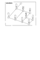
- FIG. 1 is a diagram showing a specific example of a water distribution facility in the present embodiment.
- the water distribution facility 10 in FIG. 1 supplies the water stored in the distribution reservoir 20 to the water distribution blocks 30-1 to 30-3.
- the water distribution blocks 30-1 to 30-3 represent each area included in an area to be distributed (hereinafter referred to as “distributed area”).
- the main trunk line 40 is a pipeline that serves as a trunk line that supplies the water stored in the distribution reservoir 20 to each of the distribution blocks 30-1 to 30-3.
- Flow meters 50-1 to 50-3 for measuring the amount of inflow to each water distribution block are installed at the inflow portions from the main line 40 to the water distribution blocks 30-1 to 30-3.
- Each of the water distribution blocks 30-1 to 30-3 is provided with a pipeline network for supplying water to consumers in the area.
- customers 60-1 to 60-5 exist in the water distribution block 30-1, and a pipeline network 70 is laid.
- the water supplied to the customers 60-1 to 60-5 in the water distribution block 30-1 is supplied from any one of the nodes 80-1 to 80-9 of each pipeline constituting the pipeline network 70. Water is taken.
- water supplied to the customer 60-1 is taken from the node 80-1.
- water supplied to the consumers 60-2 to 60-5 is taken from the nodes 80-2 to 80-5, respectively.
- water pressure gauges that measure water pressure are installed at some nodes of the pipeline network laid in the water distribution block.
- water pressure gauges 90-1 and 90-2 are installed at the nodes 80-4 and 80-8, respectively.
- the water leakage diagnosis apparatus of the embodiment is based on the water pressure acquired at some nodes among the nodes constituting the pipeline network laid on the distribution block for each distribution block in the distribution facility as in the above example. Estimate the amount of water leakage at each node (hereinafter referred to as “nodal water leakage”).
- the configuration of the water leakage diagnosis apparatus will be described by taking as an example the case where the water distribution block 30-1 in FIG. 1 is a diagnosis target.
- the water distribution block 30-1 is hereinafter referred to as a water distribution block 30.
- the flow meter 50-1 is referred to as a flow meter 50.
- the customers 60-1 to 60-5 existing in the water distribution block 30 are referred to as the customers 60 unless it is particularly necessary to distinguish them.
- nodes 80-1 to 80-9 are referred to as nodes 80.
- the water pressure gauges 90-1 and 90-2 are referred to as a water pressure gauge 90.
- FIG. 2 is a functional block diagram showing a functional configuration of the water leakage diagnosis apparatus 1 of the embodiment.
- the water leakage diagnosis apparatus 1 includes a CPU (Central Processing Unit) connected to the bus, a memory, an auxiliary storage device, a communication interface, and the like, and executes a water leakage diagnosis program.
- the water leakage diagnosis apparatus 1 is configured by executing a water leakage diagnosis program, the flow rate acquisition unit 11, the usage amount acquisition unit 12, the pressure acquisition unit 13, the total water leakage amount calculation unit 14, the node usage amount calculation unit 15, the node water leakage amount estimation unit 16, and the estimation. It functions as an apparatus including the parameter setting unit 17 and the diagnosis unit 18.
- All or some of the functions of the water leakage diagnosis apparatus 1 may be realized by using hardware such as ASIC (Application Specific Integrated Circuit), PLD (Programmable Logic Device), and FPGA (Field Programmable Gate Array). .
- the water leakage diagnosis program may be recorded on a computer-readable recording medium.
- the computer-readable recording medium is, for example, a portable medium such as a flexible disk, a magneto-optical disk, a ROM, a CD-ROM, or a storage device such as a hard disk built in the computer system.
- the water leakage diagnosis program may be transmitted via a telecommunication line.
- the flow rate acquisition unit 11 acquires flow rate information indicating the amount of water flowing into the pipeline network 70 from the main line 40. Flow rate information is generated in the flow meter 50.
- the flow rate acquisition unit 11 may acquire the flow rate information by communicating with the flow meter 50, or may acquire the flow rate information by accessing a storage medium in which the flow rate information is stored.
- the pressure acquisition unit 13 acquires pressure information indicating water pressure at several nodes of the pipeline network 70.
- the pressure information is generated by water pressure gauges installed at several nodes of the pipeline network 70.
- pressure information is generated by the water pressure gauge 90-1 installed at the node 80-4 and the water pressure gauge 90-2 installed at the node 80-8.
- the pressure acquisition unit 13 may acquire pressure information by communicating with the water pressure gauge 90, or may acquire pressure information by accessing a storage medium in which the pressure information is stored.
- the total water leakage calculation unit 14 calculates the total amount of water leakage in the entire pipeline network 70 (hereinafter referred to as “total water leakage”). For example, the total water leakage amount calculation unit 14 subtracts the total water leakage amount by subtracting the total amount of water usage by each customer 60 indicated by the usage amount information from the inflow amount to the pipeline network 70 indicated by the flow rate information. calculate.
- the node usage calculation unit 15 calculates the total amount of water used by the customer 60 at each node of the pipeline network 70 (hereinafter referred to as “node usage”). Specifically, the node usage amount calculation unit 15 calculates the node usage amount by summing the water usage amount of each customer 60 indicated by the usage amount information for each node of the pipeline network 70.
- the node leakage amount estimation unit 16 estimates the node leakage amount based on the actual measured values of water pressure measured at several nodes indicated by the total leakage amount, the node usage amount, and the pressure information. Specifically, the nodal leak amount estimation unit 16 includes a virtual leak amount setting unit 161, a nodal leak amount calculation unit 162, a pipe network analysis unit 163, and a pressure error evaluation unit 164.
- the virtual water leakage amount setting unit 161 sets a temporary water leakage amount (hereinafter referred to as “virtual water leakage amount”) for each node of the pipeline network.
- the virtual water leakage amount setting unit 161 sets the virtual water leakage amount so that the sum of the virtual water leakage amounts at the respective nodes becomes the total water leakage amount.
- the nodal outflow calculation unit 162 calculates the amount of water flowing out from each node due to water leakage or use by the customer 60 (hereinafter referred to as “nodal outflow”). Specifically, the node outflow amount calculation unit 162 adds the virtual water leakage amount of each node set by the virtual water leakage amount setting unit 161 and the node usage amount of each node calculated by the node usage amount calculation unit 15. Is calculated as the amount of outflow at each node.
- the pipe network analysis unit 163 calculates the pressure (effective water pressure) at each node based on the pipe network analysis model that represents the relationship between the flow rate and the water pressure in the pipe network. According to the pipe network analysis model, the pressure at each node can be calculated by the following equation (1), for example.
- i and j are identification numbers of nodes constituting the pipeline network 70.
- the node identified by i is described as node i
- the node identified by j is described as node j.
- a pipe line having a node i as a start point and a node j as an end point is referred to as a pipe line ij.
- ⁇ P ij represents the pressure difference between node i and node j. That is, ⁇ P ij represents the pressure loss [m] in the pipe line ij.
- P i represents the pressure [m] at the node i as the start point of the pipe ij, P j denotes the pressure [m] at the node j to the end point.
- L ij represents the extension [m] of the pipe line ij.
- C H represents the friction coefficient of the pipe. Friction coefficient C H is uniquely determined by the material of the conduit.
- D ij represents the pipe diameter [m].
- q ij represents a nodal outflow amount [m 3 / h] per unit time flowing through the pipe ij.
- node pressure the accuracy of the nodal outflow amount q ij greatly affects the accuracy of the pressure at each node calculated by pipe network analysis (hereinafter referred to as “node pressure”). Therefore, in order to perform pipe network analysis with high accuracy, a more accurate node usage is required.
- node pressure the accuracy of the pressure at each node calculated by pipe network analysis
- the pressure error evaluation unit 164 evaluates an error (hereinafter referred to as “pressure error”) between the estimated value and the actual measurement value of the nodal pressure calculated by the pipe network analysis unit 163. Based on the evaluation of the pressure error, the pressure error evaluation unit 164 determines the virtual water leakage amount that minimizes the node pressure error as the estimated value of the node water leakage amount. This estimation of the amount of water leakage at the node is formulated as an optimization problem as shown in the following equations (2) to (4), for example.
- Expression (2) represents an evaluation function that serves as an optimization index.
- f 1 is a function representing the square error of the measured value and estimated value of the nodal pressure.
- f 2 is a function representing the square error of the actual measurement values and estimated values of the total leakage volume.
- ⁇ 1 is a weighting factor for f 1 in the evaluation function, and ⁇ 2 is a weighting factor for f 2 .
- Expression (2) represents an optimization problem of obtaining the minimum value of the evaluation function.
- k represents the identification number of the node from which the measured value of the node pressure is obtained.
- P mk (t) represents the measured value of the nodal pressure at time t at the node identified by k (hereinafter referred to as “node k”).
- P k (t) represents the estimated value of the nodal pressure at time t at node k.
- T represents the maximum value of t.
- Q L (t) represents the total amount of water leakage at time t.
- N represents the maximum value of i.
- Q Li (t) represents an estimated value of the amount of water leakage at the node t at the node t identified by the node identification number i.
- Expression (5) is a conditional expression that represents a constraint that a possible value of the estimated value P i (t) of the nodal pressure is zero or more.
- the pressure error evaluation unit 164 obtains the minimum value of the evaluation function by solving the above optimization problem.
- the nodal water leakage amount estimation unit 16 repeatedly executes the estimation of the nodal pressure by the pipe network analysis unit 163 and the evaluation of the pressure error by the pressure error evaluation unit 164 while changing the setting of the virtual water leakage amount.
- the amount of virtual water leakage when the minimum value is taken is determined as the estimated value of node water leakage.
- the nodal water leakage estimation unit 16 outputs the nodal water leakage estimated in this way to the diagnosis unit 18. Further, the nodal water leak amount estimation unit 16 executes the nodal water leak amount estimation process a plurality of times by changing the estimation parameter.
- the estimation parameter is a parameter such as a boundary condition or an initial condition used for estimating the nodal water leakage.
- the estimation parameter is set by the estimation parameter setting unit 17.
- the estimation accuracy of the nodal water leakage amount by optimizing the pressure error depends on the number of nodes at which the nodal pressure is actually measured, that is, the number of the water pressure gauges 90.
- the reason is that, when the number of the water pressure gauges 90 is not sufficient, there is a high possibility that a plurality of virtual water leakage amount setting patterns are obtained for the same minimum pressure error.
- such an optimization method has a problem that, when the evaluation function has multimodality, only one optimal solution among a plurality of optimal solutions (here, minimum values) can be obtained. This means that even though there are a plurality of water leakage points, only one of them may be specified. Which optimum solution is obtained depends on the estimation parameter of the estimation process.
- the estimation parameters are parameters such as the initial value of the estimation process, the weighting factor of the evaluation function, the number of loops of the estimation process, the number of data used for the estimation process, and the number of nodes. Therefore, the water leakage diagnosis apparatus 1 according to the embodiment executes the estimation of the nodal water leakage amount a plurality of times using various estimation parameters in order to improve the estimation accuracy of the nodal water leakage amount.
- the estimation parameter setting unit 17 sets different estimation parameters for the plurality of node leakage amount estimation processes performed by the node leakage amount estimation unit 16.
- the diagnosis unit 18 (water leakage location estimation unit) acquires a plurality of estimation results of the amount of nodal water leakage estimated under various patterns of estimation parameters set by the estimation parameter setting unit 17, and based on the plurality of estimation results Diagnose the possibility of water leakage.
- FIG. 3 is a flowchart showing a flow of water leakage diagnosis processing by the water leakage diagnosis apparatus 1 of the embodiment.
- the total water leakage amount calculation unit 14 calculates the total water leakage amount in the entire water distribution block based on the flow rate information and the usage amount information (step S101).
- the total water leak amount calculation unit 14 outputs the calculated value of the total water leak amount to the nodal water leak amount estimation unit 16.
- the estimation parameter setting unit 17 initializes the node leakage amount estimation count K by the node leakage amount estimation unit 16 to zero (step S102).
- the estimation parameter setting unit 17 sets an estimation parameter for the nodal water leakage amount to the nodal water leakage amount estimation unit 16 (step S103).
- the nodal water leak amount estimation unit 16 performs the nodal water leak amount estimation process based on the total water leak amount, the nodal use amount, the actually measured values of the nodal pressure, and the estimation parameters set by the estimation parameter setting unit 17.
- the virtual water leakage amount setting unit 161 initializes the virtual water leakage amount setting number L to zero (step S104). When the set number of times L is initialized to zero, the virtual water leakage amount setting unit 161 sets a virtual water leakage amount at each node in the pipeline network (step S105). In addition, when it is found that the possibility of water leakage is low in advance for a specific node, the virtual water leakage amount setting unit 161 may set a virtual water leakage amount sufficiently smaller than other nodes for the node. Good. By setting such a virtual water leakage amount, it is possible to improve the estimation accuracy of the node water leakage amount.
- the node outflow amount calculation unit 162 calculates the node outflow amount based on the virtual water leakage amount at each node and the node usage amount at each node (step S106).
- the pipe network analysis unit 163 performs pipe network analysis based on the node outflow amount of each node (step S107). By executing this pipe network analysis, the pipe network analysis unit 163 calculates an estimated value of the nodal pressure at each node.
- the pressure error evaluating unit 164 calculates a pressure error between the estimated value of the nodal pressure calculated by the pipe network analyzing unit 163 and the actual measured value of the nodal pressure (step S108). Specifically, the pipe network analysis unit 163 calculates a square error between the estimated value of the nodal pressure and the measured value of the nodal pressure as a pressure error.
- the pressure error evaluation unit 164 determines whether or not the set number L of virtual water leakage amounts is equal to a preset maximum value L max (step S109). When the set number L is not equal to the maximum value L max (step S109—NO), the pressure error evaluation unit 164 increments the set number L (step S110) and returns the process to step S105.
- the virtual water leakage amount setting unit 161 sets a virtual water leakage amount with a distribution different from the past L times in the next L + 1 virtual water leakage amount setting. That is, the estimation processing node pressure is set number of times L is to equal to the maximum value L max, it is executed repeatedly based on the virtual leakage amount set in different allocation.
- the pressure error evaluation unit 164 calculates the virtual water leakage amount in the estimation result in which the pressure error becomes the minimum value among the past L estimation results. It determines as an estimated value of the amount of nodal water leakage (step S111).
- the pressure error evaluation unit 164 does not necessarily need to determine the nodal water leakage amount with a certain estimation parameter based on the L max estimation results. For example, the pressure error evaluation unit 164 may determine the virtual water leak amount at that time as an estimated value of the nodal water leak amount when a pressure error that is equal to or less than a preset threshold is obtained. In this case, the nodal water leakage amount estimation unit 16 may omit the estimation process after that point and may proceed to the estimation process using the next estimation parameter.
- the pressure error evaluating unit 164 determines whether or not the estimated number K of the nodal water leakage amount is equal to a preset maximum value K max (step S112).
- the pressure error evaluating unit 164 increments the estimated number of times K (step S113), and returns the process to step S103.
- the estimation parameter setting unit 17 sets an estimation parameter that is partially or entirely different from the past K times in the next K + 1 estimation parameter setting. That is, the nodal water leakage estimation process is repeatedly executed based on different estimation parameters until the estimation count K becomes equal to the maximum value Kmax .
- the estimation parameter setting unit 17 sets the estimation parameter for each time so that the estimation parameter value set a plurality of times has sufficient variation within a range of possible values.
- the estimated parameter setting unit 17 has a plurality of statistical values indicating the degree of variation in the values of the plurality of estimated parameters (for example, statistical values such as variance and standard deviation) so that the variation is larger than a predetermined value. Set the estimation parameters.
- the reliability of the water leakage diagnosis based on a plurality of estimation results can be improved by setting the estimation parameter having sufficient variation each time.
- the diagnosis unit 18 executes the leak diagnosis of the pipeline network based on the nodal leak amount estimated by the pressure error evaluation unit 164 (Ste S114). Specifically, the diagnosis unit 18 diagnoses the possibility of water leakage at each node based on the estimation result of the amount of node water leakage acquired for the number of times the estimation parameter is set by the estimation parameter setting unit 17.
- FIG. 4 is a diagram showing a specific example of the estimation result of the nodal water leakage amount.
- the horizontal axis represents the identification number of each node of the pipeline network
- the vertical axis represents the estimated value of the amount of water leakage at each node.
- the example of FIG. 4 shows estimated values of the amount of nodal water leakage estimated for each of the first to third types of estimation parameters. The determination of the possibility of water leakage at each node based on such an estimation result may be based on any determination standard or concept.
- the diagnosis unit 18 may determine the node 9 where water leakage is estimated from all the estimation results for each of the various estimation parameters as the water leakage location. Moreover, the diagnosis part 18 may judge the node 3 and the node 9 in which water leak is estimated by two or more types of estimation results among three types of estimation results as a water leak location. Moreover, the diagnosis part 18 judges the node 2, the node 3, the node 5, the node 8, the node 9, and the node 10 in which water leakage is estimated by one or more types of estimation results as a water leak location. May be.
- the diagnosis unit 18 may not only determine the location of the water leak, but also numerically represent the possibility of water leak at each node. For example, the diagnosis unit 18 may total the amount of node leakage obtained from each type of estimation result for each node, and may indicate the possibility of water leakage at each node by the relative magnitude of the total value. Moreover, the diagnostic part 18 may display the diagnostic result screen which shows the judgment result as mentioned above and the possibility of water leakage.
- FIG. 5 is a diagram showing a specific example of the diagnosis result screen.
- the diagnosis result screen in the example of FIG. 5 is an example in which the possibility of water leakage at each node of the pipeline network is displayed with a gauge attached to each node. By displaying such a diagnosis result screen, the manager of the pipeline network can easily determine visually which pipeline should be investigated.
- the water leakage diagnosis apparatus 1 of the embodiment configured as described above estimates a virtual water leakage amount that minimizes an error between the estimated value of the node pressure and the actual measurement value as the node water leakage amount, and the node estimated by a plurality of estimation parameters. Based on the amount of water leakage, the location of water leakage in the pipeline network is determined. By providing such a configuration, the water leakage diagnosis apparatus 1 can accurately perform water leakage diagnosis even when a sufficient number of water pressure gauges are not installed in the pipeline network.
- the accuracy of the nodal outflow q ij greatly affects the accuracy of the nodal pressure calculated by the pipe network analysis. Therefore, in order to perform pipe network analysis with high accuracy, a more accurate node usage is required.
- the meter reading data of the water tap meter connected to each node may be used for calculating the node usage.
- the meter reading data is information indicating the amount of water supplied from each water tap.
- the meter reading data is acquired as a cumulative value for each period that is somewhat long.
- meter reading data is acquired by meter reading once every two months. Therefore, when a water supply amount acquired as a cumulative value over a certain period of time (hereinafter referred to as “period water supply amount”) is used for pipe network analysis, the period water supply amount is used as a unit time for pipe network analysis (for example, 1 hour). ) For each water supply (hereinafter referred to as “unit water supply”). For example, the unit water supply amount can be acquired by applying the average daily water supply amount calculated from the period water supply amount to the daily demand pattern and apportioning it every unit time.
- the amount of water used is considered to be low at night. Therefore, depending on the size of the distribution block, the amount of water flowing into the distribution block at night may be the total amount of water leakage.
- the water leakage diagnosis device 1 may be configured to acquire the total water leakage amount based on the flow rate information. With such a configuration, it is possible to acquire the total amount of water leakage without using meter reading data in a water distribution block in which smart meters are not widely used.
- each node may be set to reflect the regional characteristics of the water distribution block. For example, a setting may be made such that a larger amount of virtual water leakage is allocated to nodes corresponding to urban areas with a large population, and a smaller amount of virtual water leakage is allocated to nodes corresponding to suburbs where the population is small.
- a setting is made so that a larger amount of virtual water leakage is assigned to a node corresponding to the predetermined area. May be.
- the water leakage diagnosis device 1 provides a nodal water leakage amount to the user of the own device when the total water leakage amount calculated based on the flow rate information or the usage amount information or the increase amount of the total water leakage amount exceeds a predetermined threshold.
- a notification unit that performs notification for prompting the determination as to whether or not to execute the estimation process.
- the water leakage diagnosis apparatus 1 includes an input unit that receives an input of the user's operation, and performs the estimation of the water leakage amount and the water leakage diagnosis according to the user instruction input in response to the notification. May be configured.
- the flow rate acquisition unit 11 may be configured to acquire total water leakage amount information indicating the total water leakage amount instead of the flow rate information.
- the water leakage diagnosis device 1 may be configured as a device that does not include the total water leakage amount calculation unit 14.
- the usage amount acquisition unit 12 may be configured to acquire node usage information indicating the node usage instead of the usage information.
- the water leakage diagnosis apparatus 1 may be configured as an apparatus that does not include the node usage amount calculation unit 15.
- a node leakage amount estimation unit that estimates a node leakage amount of each node based on a total leakage amount in the pipeline network and a node usage amount of each node of the pipeline network; It has an estimation parameter setting unit that sets an estimation parameter used for estimating the nodal water leakage amount, and a diagnosis unit, and the estimation parameter setting unit sets different estimation parameters for the nodal water leakage amount estimation process multiple times.
- the leakage amount estimation unit estimates the node leakage amount for each different estimation parameter, and the diagnosis unit estimates the number of leakage points in the pipeline network based on multiple estimation results of the node leakage amount. Even if it is not installed, the water leakage diagnosis can be performed with high accuracy.
Landscapes
- Engineering & Computer Science (AREA)
- Health & Medical Sciences (AREA)
- Life Sciences & Earth Sciences (AREA)
- Hydrology & Water Resources (AREA)
- Public Health (AREA)
- Water Supply & Treatment (AREA)
- Physics & Mathematics (AREA)
- General Physics & Mathematics (AREA)
- Fluid Mechanics (AREA)
- Acoustics & Sound (AREA)
- Mechanical Engineering (AREA)
- General Engineering & Computer Science (AREA)
- Examining Or Testing Airtightness (AREA)
- Management, Administration, Business Operations System, And Electronic Commerce (AREA)
Abstract
実施形態の漏水診断装置は、総漏水量取得部と、節点使用量取得部と、節点漏水量推定部と、推定パラメータ設定部と、漏水箇所推定部と、を持つ。総漏水量取得部は管路網に流入する水の量と、管路網内の需要家による水の使用量とに基づいて、管路網内の総漏水量を取得する。節点使用量取得部は、管路網の各節点における水の使用量の総量を示す節点使用量を取得する。節点漏水量推定部は、総漏水量と、節点使用量と、推定パラメータとに基づいて、節点漏水量を複数回推定する。漏水箇所推定部は、節点漏水量の複数の推定結果に基づいて、管路網の漏水箇所を推定する。節点漏水量推定部は、複数回の節点漏水量の推定ごとに異なる推定パラメータを用いて節点漏水量を推定する。
Description
本発明の実施形態は、漏水診断装置、漏水診断方法及びコンピュータプログラムに関する。
一般に、配水管路網における漏水の調査には、漏水の有無を調査する一次調査と、漏水箇所を特定する二次調査とがある。一次調査は調査員によって定期的に行われる調査であり、調査員は音聴棒等を用いて配水管路網における漏水の有無を調査する。二次調査は、一次調査の結果、漏水が発生している可能性が高いと判断された地域について行われる調査であり、相関式漏水探査機などを用いることにより漏水箇所が特定される。しかしながら一次調査は、調査対象の区域について均等に行われるのが一般的であり、どの地域を重点的に調査するかという考慮がなされていないのが現状である。
一方で、環境問題に対する意識の高まりを背景に水道スマートメータの導入が検討されている。水道スマートメータは、各需要家の水の使用量を随時かつ詳細に計測することを可能にする機器である。このような水道スマートメータの設置により、水需要の傾向やパターンなどを考慮した効率的な配水が可能になると考えられる。さらに、水道スマートメータによって取得される水需要量と、水圧計によって取得される配水管路網の水圧とを用いれば、配水管路網の漏水診断をより容易に行うことも可能になると考えられる。
このような方法で漏水診断を行う場合、診断の精度は配水管路網に設置された水圧計の数に左右される。しかしながら、配水管路網には必ずしも十分な精度の診断結果を得られるだけの水圧計が設置されていない場合がある。
本発明が解決しようとする課題は、十分な数の水圧計が設置されていない場合であっても精度よく漏水診断を行うことができる漏水診断装置、漏水診断方法及びコンピュータプログラムを提供することである。
実施形態の漏水診断装置は、総漏水量取得部と、節点使用量取得部と、節点漏水量推定部と、推定パラメータ設定部と、漏水箇所推定部と、を持つ。総漏水量取得部は、配水対象となる管路網に流入する水の量と、前記管路網内の需要家による水の使用量とに基づいて、前記管路網内の総漏水量を取得する。節点使用量取得部は、前記管路網の各節点における水の使用量の総量を示す節点使用量を取得する。節点漏水量推定部は、前記総漏水量取得部によって取得された前記総漏水量と、前記節点使用量取得部によって取得された前記節点使用量と、前記管路網の各節点における漏水量である節点漏水量の推定に必要な推定パラメータとに基づいて、前記節点漏水量を複数回推定する。漏水箇所推定部は、前記節点漏水量推定部による前記節点漏水量の複数の推定結果に基づいて、前記管路網における漏水箇所を推定する。前記節点漏水量推定部は、複数回の前記節点漏水量の推定ごとに異なる推定パラメータを用いて前記節点漏水量を推定する。
以下、実施形態の漏水診断装置、漏水診断方法及びコンピュータプログラムを、図面を参照して説明する。
図1は、本実施形態における配水設備の具体例を示す図である。図1の配水設備10は、配水池20に蓄えられた水を配水ブロック30-1~30-3に供給する。配水ブロック30-1~30-3は、配水対象となる地域(以下、「配水対象地域」という。)に含まれる各区域を表す。主幹線40は、配水池20に蓄えられた水を配水ブロック30-1~30-3のそれぞれに送水する幹線となる管路である。主幹線40から配水ブロック30-1~30-3のそれぞれへの流入部には、各配水ブロックへの流入量を計測する流量計50-1~50-3が設置されている。
配水ブロック30-1~30-3のそれぞれには、区域内の需要家に水を供給するための管路網が敷設されている。例えば配水ブロック30-1には需要家60-1~60-5が存在し、管路網70が敷設されている。配水ブロック30-1内の需要家60-1~60-5に供給される水は、管路網70を構成する各管路の節点80-1~80-9のうちのいずれかの節点から取水される。例えば需要家60-1に供給される水は、節点80-1から取水される。同様に、需要家60-2~60-5に供給される水は、それぞれ、節点80-2~節点80-5から取水される。なお、需要家60-1~60-5による水の使用量は、需要家60-1~60-5ごとに設置された水道スマートメータ(以下、「スマートメータ」という。)によって計測される。例えば、各需要家の水の使用量は、1時間ごとに1リットル単位で計測される。
また、配水ブロックに敷設された管路網のいくつかの節点には水圧を計測する水圧計が設置されている。例えば配水ブロック30-1では、節点80-4及び80-8にそれぞれ水圧計90-1及び90-2が設置されている。
実施形態の漏水診断装置は、上記の例のような配水設備における各配水ブロックについて、配水ブロックに敷設された管路網を構成する節点のうち、一部の節点で取得される水圧に基づいて各節点における漏水量(以下、「節点漏水量」という。)を推定する。
以下、図1の配水ブロック30-1が診断対象である場合を例に、実施形態の漏水診断装置の構成について説明する。なお、説明を簡単にするため、以下では配水ブロック30-1を配水ブロック30と記載する。同様に、流量計50-1を流量計50と記載する。
また、同様の理由により、特に区別する必要がない限りにおいては、配水ブロック30内に存在する需要家60-1~60-5を需要家60と記載する。同様に、節点80-1~80-9を節点80と記載する。同様に、水圧計90-1及び90-2を水圧計90と記載する。
また、同様の理由により、特に区別する必要がない限りにおいては、配水ブロック30内に存在する需要家60-1~60-5を需要家60と記載する。同様に、節点80-1~80-9を節点80と記載する。同様に、水圧計90-1及び90-2を水圧計90と記載する。
図2は、実施形態の漏水診断装置1の機能構成を示す機能ブロック図である。漏水診断装置1は、バスで接続されたCPU(Central Processing Unit)やメモリ、補助記憶装置、通信インターフェースなどを備え、漏水診断プログラムを実行する。漏水診断装置1は、漏水診断プログラムの実行によって流量取得部11、使用量取得部12、圧力取得部13、総漏水量算出部14、節点使用量算出部15、節点漏水量推定部16、推定パラメータ設定部17及び診断部18を備える装置として機能する。なお、漏水診断装置1の各機能の全て又は一部は、ASIC(Application Specific Integrated Circuit)やPLD(Programmable Logic Device)やFPGA(Field Programmable Gate Array)等のハードウェアを用いて実現されてもよい。漏水診断プログラムは、コンピュータ読み取り可能な記録媒体に記録されてもよい。コンピュータ読み取り可能な記録媒体とは、例えばフレキシブルディスク、光磁気ディスク、ROM、CD-ROM等の可搬媒体、コンピュータシステムに内蔵されるハードディスク等の記憶装置である。漏水診断プログラムは、電気通信回線を介して送信されてもよい。
流量取得部11は、主幹線40から管路網70に流入する水の量を示す流量情報を取得する。流量情報は流量計50において生成される。流量取得部11は、流量計50と通信することによって流量情報を取得してもよいし、流量情報が記憶された記憶媒体にアクセスすることによって流量情報を取得してもよい。
使用量取得部12は、配水ブロック30に存在する需要家60による水の使用量を示す使用量情報を取得する。使用量情報は、それぞれの需要家60ごとに設置されたスマートメータによって生成される。使用量取得部12は、スマートメータと通信することによって使用量情報を取得してもよいし、使用量情報が記憶された記憶媒体にアクセスすることによって使用量情報を取得してもよい。
圧力取得部13は、管路網70のいくつかの節点における水圧を示す圧力情報を取得する。圧力情報は、管路網70のいくつかの節点に設置された水圧計によって生成される。例えば、図1の配水設備10では、節点80-4に設置された水圧計90-1と、節点80-8に設置された水圧計90-2とによって圧力情報が生成される。圧力取得部13は、水圧計90と通信することによって圧力情報を取得してもよいし、圧力情報が記憶された記憶媒体にアクセスすることによって圧力情報を取得してもよい。
総漏水量算出部14(総漏水量取得部)は、管路網70の全体での漏水量の総量(以下、「総漏水量」という。)を算出する。例えば、総漏水量算出部14は、流量情報が示す管路網70への流入量から、使用量情報が示すそれぞれの需要家60による水の使用量の総和を減算することにより総漏水量を算出する。
節点使用量算出部15(節点使用量取得部)は、管路網70の各節点における需要家60による水の使用量の総量(以下、「節点使用量」という。)を算出する。具体的には、節点使用量算出部15は、使用量情報が示す各需要家60の水の使用量を管路網70の各節点ごとに合計することにより、節点使用量を算出する。
節点漏水量推定部16は、総漏水量、節点使用量及び圧力情報が示すいくつかの節点で計測された水圧の実測値に基づいて節点漏水量を推定する。具体的には、節点漏水量推定部16は、仮想漏水量設定部161、節点流出量算出部162、管網解析部163及び圧力誤差評価部164を備える。
仮想漏水量設定部161は、管路網の各節点について仮の漏水量(以下、「仮想漏水量」という。)を設定する。仮想漏水量設定部161は、各節点の仮想漏水量の総和が総漏水量となるように仮想漏水量を設定する。
節点流出量算出部162は、漏水又は需要家60の使用によって各節点から流出する水量(以下、「節点流出量」という。)を算出する。具体的には、節点流出量算出部162は、仮想漏水量設定部161により設定された各節点の仮想漏水量と、節点使用量算出部15によって算出された各節点の節点使用量との合計を各節点の節点流出量として算出する。
管網解析部163は、管路網における流量と水圧との関係を表す管網解析モデルに基づいて各節点における圧力(有効水圧)を算出する。管網解析モデルによれば、各節点における圧力は、例えば次の式(1)によって算出することができる。

式(1)において、i及びjは管路網70を構成する節点の識別番号である。以下では、iで識別される節点を節点iと記載し、jで識別される節点を節点jと記載する。また、節点iを始点とし、節点jを終点とする管路を管路ijと記載する。ΔPijは節点iと節点jとの間の圧力差を表す。すなわち、ΔPijは、管路ijでの圧力損失[m]を表す。Piは管路ijの始点となる節点iにおける水圧[m]を表し、Pjは終点となる節点jにおける水圧[m]を表す。Lijは管路ijの延長[m]を表す。CHは管路の摩擦係数を表す。摩擦係数CHは管路の材質によって一意に決定される。Dijは管路の口径[m]を表す。qijは管路ijを流れる単位時間当たりの節点流出量[m3/h]を表す。
なお、管網解析によって算出される各節点における圧力(以下、「節点圧力」という。)の精度には、節点流出量qijの精度が大きく影響する。そのため、管網解析を精度よく行うためには、より正確な節点使用量が必要となる。需要家ごとにスマートメータが設置された配水ブロックでは、各需要家のスマートメータによって計測される水の使用量を対応する節点ごとに合計することにより正確な節点使用量を取得することが可能である。
圧力誤差評価部164は、管網解析部163によって算出された節点圧力の推定値と実測値との誤差(以下、「圧力誤差」という。)を評価する。この圧力誤差の評価により、圧力誤差評価部164は、節点圧力の誤差が最小となる仮想漏水量を節点漏水量の推定値として決定する。この節点漏水量の推定は、例えば次の式(2)~式(4)に示されるような最適化問題として定式化される。




式(2)は、最適化の指標となる評価関数を表している。f1は、節点圧力の実測値及び推定値の二乗誤差を表す関数である。f2は、総漏水量の実測値及び推定値の二乗誤差を表す関数である。α1は、評価関数におけるf1に対する重み係数であり、α2はf2に対する重み係数である。式(2)は、評価関数の最小値を求めるという最適化問題を表している。
式(3)においてkは節点圧力の実測値が得られている節点の識別番号を表す。Mはkの最大値を表す。仮に節点番号1、10の節点において節点圧力が計測されている場合には、M=2となる。Pmk(t)は、kで識別される節点(以下、「節点k」という。)における時間tでの節点圧力の実測値を表す。Pk(t)は、節点kにおける時間tでの節点圧力の推定値を表す。Tはtの最大値を表す。
式(4)においてQL(t)は、時間tでの総漏水量を表す。Nはiの最大値を表す。QLi(t)は、節点の識別番号iで識別される節点iにおける時間tでの節点漏水量の推定値を表す。式(5)は、節点圧力の推定値Pi(t)が取り得る値がゼロ以上であるという制約を表す条件式である。圧力誤差評価部164は、上記の最適化問題を解くことにより、評価関数の最小値を求める。
節点漏水量推定部16は、管網解析部163による節点圧力の推定と、圧力誤差評価部164による圧力誤差の評価と、を仮想漏水量の設定を変えて繰り返し実行することにより、評価関数が最小値をとるときの仮想漏水量を節点漏水量の推定値として決定する。節点漏水量推定部16は、このようにして推定された節点漏水量を診断部18に出力する。また、節点漏水量推定部16は、上記の節点漏水量の推定処理を、推定パラメータを変更して複数回実行する。推定パラメータは、節点漏水量の推定に用いられる境界条件や初期条件などのパラメータである。推定パラメータは、推定パラメータ設定部17によって設定される。
上記のように圧力誤差を最適化することによる節点漏水量の推定精度は、節点圧力が実測されている節点の数、すなわち水圧計90の数に依存する。その理由は、水圧計90の数が十分でない場合、同じ圧力誤差の最小値に対して複数の仮想漏水量の設定パターンが得られる可能性が高くなるためである。また、このような最適化手法には、評価関数が多峰性を有する場合、複数の最適解(ここでは極小値)のうちの1つの最適解しか得ることができないという問題がある。これはすなわち、複数の漏水箇所が存在するにも関わらず、そのうちの1箇所しか特定することができない可能性があることを意味する。どの最適解が得られるかは、推定処理の推定パラメータに依存する。例えば、推定パラメータは、推定処理の初期値や評価関数の重み係数、推定処理のループ回数、推定処理に用いるデータ数や節点数などのパラメータである。そのため、実施形態の漏水診断装置1は、節点漏水量の推定精度を高めるために、節点漏水量の推定を様々な推定パラメータを用いて、複数回実行する。推定パラメータ設定部17は、節点漏水量推定部16が行う複数回の節点漏水量の推定処理に対して、それぞれ異なる推定パラメータを設定する。
診断部18(漏水箇所推定部)は、推定パラメータ設定部17によって設定される様々なパターンの推定パラメータの下で推定された節点漏水量の推定結果を複数取得し、複数の推定結果に基づいて漏水の可能性を診断する。
図3は、実施形態の漏水診断装置1による漏水診断処理の流れを示すフローチャートである。まず、総漏水量算出部14が、流量情報と使用量情報とに基づいて、配水ブロック全域での総漏水量を算出する(ステップS101)。総漏水量算出部14は、算出した総漏水量の値を節点漏水量推定部16に出力する。
続いて、推定パラメータ設定部17が、節点漏水量推定部16による節点漏水量の推定回数Kをゼロに初期化する(ステップS102)。推定パラメータ設定部17は、推定回数Kをゼロに初期化すると、節点漏水量推定部16に対して節点漏水量の推定パラメータを設定する(ステップS103)。節点漏水量推定部16は、総漏水量、節点使用量、節点圧力の実測値と、推定パラメータ設定部17によって設定された推定パラメータと、に基づいて節点漏水量の推定処理を実行する。
具体的には、仮想漏水量設定部161が、仮想漏水量の設定回数Lをゼロに初期化する(ステップS104)。仮想漏水量設定部161は、設定回数Lをゼロに初期化すると、管路網内の各節点に仮想漏水量を設定する(ステップS105)。なお、特定の節点について予め漏水の可能性が低いことが判明している場合、仮想漏水量設定部161は、当該節点に対して他の節点よりも十分に少ない仮想漏水量を設定してもよい。このような仮想漏水量を設定することにより、節点漏水量の推定精度を向上させることができる。
節点流出量算出部162は、各節点の仮想漏水量と、各節点の節点使用量と、に基づいて節点流出量を算出する(ステップS106)。管網解析部163は、各節点の節点流出量に基づいて管網解析を実行する(ステップS107)。この管網解析の実行により、管網解析部163は、各節点における節点圧力の推定値を算出する。
圧力誤差評価部164は、管網解析部163によって算出された節点圧力の推定値と、節点圧力の実測値との圧力誤差を算出する(ステップS108)。具体的には、管網解析部163は、節点圧力の推定値と、節点圧力の実測値との二乗誤差を圧力誤差として算出する。
続いて圧力誤差評価部164は、仮想漏水量の設定回数Lが予め設定された最大値Lmaxに等しいか否かを判定する(ステップS109)。設定回数Lが最大値Lmaxに等しくない場合(ステップS109-NO)、圧力誤差評価部164は設定回数Lをインクリメントして(ステップS110)、ステップS105に処理を戻す。なお、仮想漏水量設定部161は、次のL+1回目の仮想漏水量の設定においては、過去L回と異なる配分の仮想漏水量を設定する。すなわち、節点圧力の推定処理は、設定回数Lが最大値Lmaxに等しくなるまで、異なる配分で設定された仮想漏水量に基づいて繰り返し実行される。
一方、設定回数Lが最大値Lmaxに等しい場合(ステップS109-YES)、圧力誤差評価部164は、過去L回の推定結果のうち、圧力誤差が最小値となる推定結果における仮想漏水量を節点漏水量の推定値として決定する(ステップS111)。
なお、圧力誤差評価部164は、ある推定パラメータでの節点漏水量の決定を、必ずしもLmax回の推定結果に基づいて行う必要はない。例えば、圧力誤差評価部164は、予め設定された閾値以下となる圧力誤差が得られた時点で、その時点での仮想漏水量を節点漏水量の推定値として決定してもよい。この場合、節点漏水量推定部16は、その時点以降の推定処理を省略して、次の推定パラメータでの推定処理に移行してもよい。
続いて圧力誤差評価部164は、節点漏水量の推定回数Kが予め設定された最大値Kmaxに等しいか否かを判定する(ステップS112)。推定回数Kが最大値Kmaxに等しくない場合(ステップS112-NO)、圧力誤差評価部164は推定回数Kをインクリメントして(ステップS113)、ステップS103に処理を戻す。なお、推定パラメータ設定部17は、次のK+1回目の推定パラメータの設定においては、過去K回と一部又は全部のパラメータ値が異なる推定パラメータを設定する。すなわち、節点漏水量の推定処理は、推定回数Kが最大値Kmaxに等しくなるまで、異なる推定パラメータに基づいて繰り返し実行される。
また、推定パラメータ設定部17は、複数回設定される推定パラメータの値が、取り得る値の範囲で十分なばらつきを持つように各回の推定パラメータを設定する。例えば、推定パラメータ設定部17は、複数の推定パラメータの値のばらつきの度合いを示す統計値(例えば、分散や標準偏差等の統計値)が、所定以上の大きさのばらつきを示すように複数の推定パラメータを設定する。このように各回で十分なばらつきを持つ推定パラメータが設定されることにより、複数の推定結果に基づく漏水診断の信頼性を向上させることができる。
一方、設定回数Kが最大値Kmaxに等しい場合(ステップS112-YES)、圧力誤差評価部164によって推定された節点漏水量に基づいて、診断部18が管路網の漏水診断を実行する(ステップS114)。具体的には、診断部18は、推定パラメータ設定部17によって推定パラメータが設定された回数分取得された節点漏水量の推定結果に基づいて、各節点における漏水の可能性を診断する。
図4は、節点漏水量の推定結果の具体例を示す図である。図4において、横軸は管路網の各節点の識別番号を表し、縦軸は各節点における節点漏水量の推定値を表す。図4の例は、第1~第3の3種類の推定パラメータごとに推定された節点漏水量の推定値を示している。このような推定結果に基づく各節点における漏水の可能性の判断は、どのような判断基準や考え方に基づくものであってもよい。
例えば図4の例の場合、診断部18は、各種推定パラメータごとの推定結果の全てで漏水が推定されている節点9を漏水箇所と判断してもよい。また、診断部18は、3種類の推定結果のうち、2種類以上の推定結果で漏水が推定されている節点3及び節点9を漏水箇所と判断してもよい。また、診断部18は、3種類の推定結果のうち、1種類以上の推定結果で漏水が推定されている節点2、節点3、節点5、節点8、節点9及び節点10を漏水箇所と判断してもよい。
また、診断部18は、漏水箇所の判断だけでなく、各節点における漏水の可能性を数値で表すようにしてもよい。例えば、診断部18は、各種類の推定結果で得られた節点漏水量を節点ごとに合計し、合計値の相対的な大小により各節点における漏水の可能性を表してもよい。また、診断部18は、上記のような判断結果や漏水の可能性を示す診断結果画面を表示してもよい。
図5は、診断結果画面の具体例を示す図である。図5の例の診断結果画面は、管路網の各節点における漏水の可能性を、節点ごとに付したゲージで表示した例である。このような診断結果画面が表示されることにより、管路網の管理者は、どの管路を優先的に調査すべきかを視覚によって容易に判断することが可能となる。
このように構成された実施形態の漏水診断装置1は、節点圧力の推定値と実測値との誤差が最小となる仮想漏水量を節点漏水量として推定し、複数の推定パラメータにより推定された節点漏水量に基づいて、管路網における漏水箇所を判定する。このような構成を備えることにより、漏水診断装置1は、管路網内に十分な数の水圧計が設置されていない場合あっても精度よく漏水診断を行うことができる。
以下、実施形態の漏水診断装置1の変形例について説明する。
上述したとおり、管網解析によって算出される節点圧力の精度には、節点流出量qijの精度が大きく影響する。そのため、管網解析を精度よく行うためには、より正確な節点使用量が必要となる。しかしながら、スマートメータが十分に普及していない配水ブロックでは、個々の需要家の水の使用量を正確に把握できない可能性がある。そのため、スマートメータが普及していない配水ブロックでは、節点使用量の算出に、各節点に接続されている給水栓メータの検針データが用いられてもよい。検針データは、各給水栓による給水量を示す情報である。
ただし、一般には、検針データは、ある程度長い期間ごとの累積値として取得される。例えば、検針データは2ヶ月に一度の検針によって取得される。そのため、このようにある程度長い期間の累積値として取得される給水量(以下、「期間給水量」という。)を管網解析に用いる場合、期間給水量を管網解析の単位時間(例えば1時間)ごとの給水量(以下、「単位給水量」という。)に換算することが必要となる。例えば、単位給水量は、期間給水量から算出される一日の平均給水量を一日の需要パターンに当てはめて単位時間ごとに按分することにより取得可能である。
ただし、一般には、検針データは、ある程度長い期間ごとの累積値として取得される。例えば、検針データは2ヶ月に一度の検針によって取得される。そのため、このようにある程度長い期間の累積値として取得される給水量(以下、「期間給水量」という。)を管網解析に用いる場合、期間給水量を管網解析の単位時間(例えば1時間)ごとの給水量(以下、「単位給水量」という。)に換算することが必要となる。例えば、単位給水量は、期間給水量から算出される一日の平均給水量を一日の需要パターンに当てはめて単位時間ごとに按分することにより取得可能である。
また、一般に、夜間は水の使用量が少ないと考えられる。そのため、配水ブロックの規模によっては、夜間における配水ブロックへの流入量が、総漏水量となる場合もある。このような場合、漏水診断装置1は、流量情報に基づいて総漏水量を取得するように構成されてもよい。このような構成により、スマートメータが普及していない配水ブロックにおいて、検針データを用いることなく総漏水量を取得することが可能となる。
また、各節点には、配水ブロックの地域特性を反映した設定がなされてもよい。例えば、人口の多い都市部に該当する節点にはより多くの仮想漏水量が割り当てられ、人口の少ない郊外に該当する節点にはより少ない仮想漏水量が割り当てられるような設定がなされてもよい。また例えば、所定の地域(例えば繁華街等)での漏水が多いことが予め判明している場合には、上記所定の地域に該当する節点により多くの仮想漏水量が割り当てられるような設定がなされてもよい。このような地域特性を反映させることにより、より現実に合った漏水箇所の推定を行うことが可能となる。
漏水診断装置1は、流量情報や使用量情報に基づいて算出される総漏水量又は総漏水量の増加量が所定の閾値を越えた場合に、自装置の利用者に対して、節点漏水量の推定処理を実行するか否かの判断を促す通知を行う通知部を備えてもよい。この場合、漏水診断装置1は、利用者の操作の入力を受け付ける入力部を備え、上記通知に対して入力される利用者の指示に応じて、節点漏水量の推定ならびに漏水診断を実行するように構成されてもよい。
流量取得部11は、流量情報に代えて、総漏水量を示す総漏水量情報を取得するように構成されてもよい。この場合、漏水診断装置1は、総漏水量算出部14を備えない装置として構成されてもよい。同様に、使用量取得部12は、使用量情報に代えて、節点使用量を示す節点使用量情報を取得するように構成されてもよい。この場合、漏水診断装置1は、節点使用量算出部15を備えない装置として構成されてもよい。
以上説明した少なくともひとつの実施形態によれば、管路網における総漏水量と管路網の各節点の節点使用量とに基づいて各節点の節点漏水量を推定する節点漏水量推定部と、節点漏水量の推定に用いられる推定パラメータを設定する推定パラメータ設定部と、診断部とを持ち、推定パラメータ設定部が複数回の節点漏水量の推定処理に対して異なる推定パラメータを設定し、節点漏水量推定部が異なる推定パラメータごとに節点漏水量を推定し、診断部が節点漏水量の複数の推定結果に基づいて管路網における漏水箇所を推定することにより、十分な数の水圧計が設置されていない場合あっても精度よく漏水診断を行うことができる。
本発明のいくつかの実施形態を説明したが、これらの実施形態は、例として提示したものであり、発明の範囲を限定することは意図していない。これら実施形態は、その他の様々な形態で実施されることが可能であり、発明の要旨を逸脱しない範囲で、種々の省略、置き換え、変更を行うことができる。これら実施形態やその変形は、発明の範囲や要旨に含まれると同様に、特許請求の範囲に記載された発明とその均等の範囲に含まれるものである。
Claims (9)
- 配水対象となる管路網に流入する水の量と、前記管路網内の需要家による水の使用量とに基づいて、前記管路網内の総漏水量を取得する総漏水量取得部と、
前記管路網の各節点における水の使用量の総量を示す節点使用量を取得する節点使用量取得部と、
前記総漏水量取得部によって取得された前記総漏水量と、前記節点使用量取得部によって取得された前記節点使用量と、前記管路網の各節点における漏水量である節点漏水量の推定に必要な推定パラメータとに基づいて、前記節点漏水量を複数回推定する節点漏水量推定部と、
前記節点漏水量推定部による前記節点漏水量の複数回の推定結果に基づいて、前記管路網における漏水箇所を推定する漏水箇所推定部と、
を備え、
前記節点漏水量推定部は、複数回の前記節点漏水量の推定ごとに異なる推定パラメータを用いて前記節点漏水量を推定する、
漏水診断装置。 - 前記節点漏水量推定部は、
前記総漏水量取得部により取得された前記総漏水量を前記管路網の各節点に配分することにより、各節点における漏水量を仮想漏水量として設定する仮想漏水量設定部と、
前記仮想漏水量設定部により設定された各節点の仮想漏水量と、前記節点使用量取得部によって取得された各節点の節点使用量とに基づいて、各節点から流出する水量を示す節点流出量を算出する節点流出量算出部と、
前記節点流出量に基づいて管網解析を実行することにより前記管路網内の各節点における圧力である節点圧力を推定する管網解析部と、
を備え、
前記仮想漏水量設定部は、前記管網解析部が行う複数回の推定処理に対して異なる仮想漏水量を設定し、
前記節点漏水量推定部は、前記管網解析部による前記節点圧力の複数の推定結果に基づいて、前記節点圧力の推定値と、前記管路網内のいくつかの節点で取得された節点圧力の実測値との差が、最小となる仮想漏水量を各節点における漏水量の推定値として決定する圧力誤差評価部をさらに備える、
請求項1に記載の漏水診断装置。 - 前記節点漏水量推定部が行う複数回の推定処理に用いられる複数の推定パラメータは、前記複数の推定パラメータの値のばらつきの度合いを示す統計値が所定以上の大きさのばらつきを示すように決定される、
請求項1又は2に記載の漏水診断装置。 - 前記仮想漏水量設定部は、前記管路網の各節点に対して、各節点に対応する地域の特性に応じて重み付けされた仮想漏水量を設定する、
請求項2又は3に記載の漏水診断装置。 - 前記総漏水量取得部は、前記需要家による夜間の水の使用量をゼロとみなすことで、夜間において前記管路網に流入する水の量を前記総漏水量として取得する、
請求項1から4のいずれか一項に記載の漏水診断装置。 - 前記総漏水量又は前記総漏水量の増加量が所定の閾値を越えた場合に、自装置の利用者に対して、前記節点漏水量の推定処理を実行するか否かの判断を促す通知を行う通知部をさらに備える、
請求項1から5のいずれか一項に記載の漏水診断装置。 - 前記仮想漏水量設定部は、予め漏水の可能性が低いことが判明している節点に対して、他の節点よりも十分に少ない仮想漏水量を設定する、
請求項2から6のいずれか一項に記載の漏水診断装置。 - 配水対象となる管路網に流入する水の量と、前記管路網内の需要家による水の使用量とに基づいて、前記管路網内の総漏水量を取得する総漏水量取得ステップと、
前記管路網の各節点における水の使用量の総量を示す節点使用量を取得する節点使用量取得ステップと、
前記総漏水量取得ステップにおいて取得された前記総漏水量と、前記節点使用量取得ステップにおいて取得された前記節点使用量と、前記管路網の各節点における漏水量である節点漏水量の推定に必要な推定パラメータとに基づいて、前記節点漏水量を複数回推定する節点漏水量推定ステップと、
前記節点漏水量推定ステップにおける前記節点漏水量の複数の推定結果に基づいて、前記管路網における漏水箇所を推定する漏水箇所推定ステップと、
前記節点漏水量推定ステップにおいて、複数回の前記節点漏水量の推定ごとに異なる推定パラメータを用いて前記節点漏水量を推定するステップと、
を有する漏水診断方法。 - 配水対象となる管路網に流入する水の量と、前記管路網内の需要家による水の使用量とに基づいて、前記管路網内の総漏水量を取得する総漏水量取得ステップと、
前記管路網の各節点における水の使用量の総量を示す節点使用量を取得する節点使用量取得ステップと、
前記総漏水量取得ステップにおいて取得された前記総漏水量と、前記節点使用量取得ステップにおいて取得された前記節点使用量と、前記管路網の各節点における漏水量である節点漏水量の推定に必要な推定パラメータとに基づいて、前記節点漏水量を複数回推定する節点漏水量推定ステップと、
前記節点漏水量推定ステップにおける前記節点漏水量の複数の推定結果に基づいて、前記管路網における漏水箇所を推定する漏水箇所推定ステップと、
前記節点漏水量推定ステップにおいて、複数回の前記節点漏水量の推定ごとに異なる推定パラメータを用いて前記節点漏水量を推定するステップと、
をコンピュータに実行させるためのコンピュータプログラム。
Priority Applications (2)
| Application Number | Priority Date | Filing Date | Title |
|---|---|---|---|
| CN201680055069.1A CN108350688B (zh) | 2015-09-25 | 2016-08-03 | 漏水诊断装置、漏水诊断方法以及计算机程序 |
| US15/933,622 US20180209124A1 (en) | 2015-09-25 | 2018-03-23 | Water leakage diagnosis device, water leakage diagnosis method, and non-transitory computer readable storage medium |
Applications Claiming Priority (2)
| Application Number | Priority Date | Filing Date | Title |
|---|---|---|---|
| JP2015188396A JP6625851B2 (ja) | 2015-09-25 | 2015-09-25 | 漏水診断装置、漏水診断方法及びコンピュータプログラム |
| JP2015-188396 | 2015-09-25 |
Related Child Applications (1)
| Application Number | Title | Priority Date | Filing Date |
|---|---|---|---|
| US15/933,622 Continuation US20180209124A1 (en) | 2015-09-25 | 2018-03-23 | Water leakage diagnosis device, water leakage diagnosis method, and non-transitory computer readable storage medium |
Publications (1)
| Publication Number | Publication Date |
|---|---|
| WO2017051617A1 true WO2017051617A1 (ja) | 2017-03-30 |
Family
ID=58386050
Family Applications (1)
| Application Number | Title | Priority Date | Filing Date |
|---|---|---|---|
| PCT/JP2016/072822 Ceased WO2017051617A1 (ja) | 2015-09-25 | 2016-08-03 | 漏水診断装置、漏水診断方法及びコンピュータプログラム |
Country Status (4)
| Country | Link |
|---|---|
| US (1) | US20180209124A1 (ja) |
| JP (1) | JP6625851B2 (ja) |
| CN (1) | CN108350688B (ja) |
| WO (1) | WO2017051617A1 (ja) |
Families Citing this family (9)
| Publication number | Priority date | Publication date | Assignee | Title |
|---|---|---|---|---|
| EP3789547A4 (en) * | 2018-06-11 | 2021-12-08 | Hitachi, Ltd. | WATER LEAK DETECTION PROCESS, WATER LEAK DETECTION DEVICE AND VIBRATION SENSOR TERMINAL |
| US20200320650A1 (en) * | 2019-04-05 | 2020-10-08 | I D Technologies Inc. | Multi-utility integrity monitoring and display system |
| GB2586775B (en) * | 2019-06-11 | 2022-03-02 | Syrinix Ltd | Rising main pipeline assessment system and method |
| CN112381382B (zh) * | 2020-11-12 | 2021-11-26 | 深圳市拓安信计控仪表有限公司 | 一种漏损管理方法、漏损管理装置及终端设备 |
| GB202114709D0 (en) * | 2021-10-14 | 2021-12-01 | Syrinix Ltd | Burst detection on pumped rising mains |
| CN113970073B (zh) * | 2021-11-11 | 2023-05-19 | 吉林大学 | 一种基于ResNet的供水管网泄漏精准定位方法 |
| DE102021131635B4 (de) * | 2021-12-01 | 2025-12-18 | 50K UG (haftungsbeschränkt) | System, Detektoreinheit und Verfahren zum Erkennen einer Leckage eines Wasserleitungssystems |
| CN115167547B (zh) * | 2022-06-29 | 2023-06-23 | 深圳拓安信物联股份有限公司 | 供水管网的调压方法及调压设备 |
| TWI866457B (zh) * | 2023-09-11 | 2024-12-11 | 弓銓企業股份有限公司 | 找出供水管網漏水熱區的方法 |
Citations (3)
| Publication number | Priority date | Publication date | Assignee | Title |
|---|---|---|---|---|
| JPS5289370A (en) * | 1976-01-21 | 1977-07-26 | Hitachi Ltd | Water-leaking position detecting apparatus |
| JP2013178207A (ja) * | 2012-02-29 | 2013-09-09 | Hitachi Ltd | 漏水検知装置 |
| JP5329871B2 (ja) * | 2008-08-25 | 2013-10-30 | 株式会社東芝 | 漏水節点推定装置 |
Family Cites Families (8)
| Publication number | Priority date | Publication date | Assignee | Title |
|---|---|---|---|---|
| JP4822990B2 (ja) * | 2006-09-07 | 2011-11-24 | 株式会社東芝 | 漏水監視システム |
| CN102213363B (zh) * | 2010-04-01 | 2013-11-06 | 财团法人交大思源基金会 | 管网渗漏侦测方法和装置 |
| FR2984455B1 (fr) * | 2011-12-14 | 2015-01-16 | Veolia Eau Cie Generale Des Eaux | Procede et dispositif d'injection de produit d'addition dans une canalisation de liquide |
| US8930150B2 (en) * | 2012-02-01 | 2015-01-06 | International Business Machines Corporation | Leak detection in a fluid distribution network |
| CN102606891B (zh) * | 2012-04-11 | 2014-06-25 | 广州东芝白云自动化系统有限公司 | 漏水检测仪及检测系统、及检测方法 |
| CN102865459A (zh) * | 2012-09-26 | 2013-01-09 | 华北电力大学(保定) | 一种供热管网泄漏定位系统及定位方法 |
| JP6273125B2 (ja) * | 2013-11-12 | 2018-01-31 | 株式会社日立製作所 | 漏水調査計画立案装置、漏水調査計画立案システム、及び漏水調査計画立案方法 |
| US10203262B2 (en) * | 2014-02-19 | 2019-02-12 | Tata Consultancy Services Limited | Leak localization in water distribution networks |
-
2015
- 2015-09-25 JP JP2015188396A patent/JP6625851B2/ja active Active
-
2016
- 2016-08-03 WO PCT/JP2016/072822 patent/WO2017051617A1/ja not_active Ceased
- 2016-08-03 CN CN201680055069.1A patent/CN108350688B/zh active Active
-
2018
- 2018-03-23 US US15/933,622 patent/US20180209124A1/en not_active Abandoned
Patent Citations (3)
| Publication number | Priority date | Publication date | Assignee | Title |
|---|---|---|---|---|
| JPS5289370A (en) * | 1976-01-21 | 1977-07-26 | Hitachi Ltd | Water-leaking position detecting apparatus |
| JP5329871B2 (ja) * | 2008-08-25 | 2013-10-30 | 株式会社東芝 | 漏水節点推定装置 |
| JP2013178207A (ja) * | 2012-02-29 | 2013-09-09 | Hitachi Ltd | 漏水検知装置 |
Also Published As
| Publication number | Publication date |
|---|---|
| JP2017061823A (ja) | 2017-03-30 |
| CN108350688A (zh) | 2018-07-31 |
| JP6625851B2 (ja) | 2019-12-25 |
| CN108350688B (zh) | 2020-10-27 |
| US20180209124A1 (en) | 2018-07-26 |
Similar Documents
| Publication | Publication Date | Title |
|---|---|---|
| JP6625851B2 (ja) | 漏水診断装置、漏水診断方法及びコンピュータプログラム | |
| JP5756767B2 (ja) | 漏水検知装置 | |
| EP3568681B1 (en) | Method and apparatus for model-based leak detection of a pipe network | |
| JP6273125B2 (ja) | 漏水調査計画立案装置、漏水調査計画立案システム、及び漏水調査計画立案方法 | |
| JP5329871B2 (ja) | 漏水節点推定装置 | |
| JP6318053B2 (ja) | 漏水分布推定装置 | |
| Güngör-Demirci et al. | Determinants of non-revenue water for a water utility in California | |
| PT2477088E (pt) | Sistema e método para identificar localizações geográficas prováveis de anomalias numa rede de fornecimento de água | |
| JP2015094665A5 (ja) | ||
| CN109716090B (zh) | 一种用于估计配水管网的子网边界处的水流量的改进系统 | |
| WO2015063931A1 (ja) | 漏水検知装置、漏水検知システム、及び漏水検知方法 | |
| Vrachimis et al. | Real-time hydraulic interval state estimation for water transport networks: A case study | |
| JP6547989B1 (ja) | 漏洩判定装置、漏洩判定システム、漏洩判定方法およびプログラム | |
| JP2014145603A (ja) | 漏水推定装置及びシステム及び方法 | |
| CN106575312B (zh) | 用于检测配送网络特别是水配送网络中的异常的方法 | |
| JP6018970B2 (ja) | 配水制御装置および方法 | |
| JP2014054151A (ja) | 輸送ネットワークのグラフ構造構築装置、グラフ構造構築システム、グラフ構造構築方法及びグラフ構造構築プログラム | |
| JP5864753B2 (ja) | 物理量推定システム及び物理量推定方法 | |
| Ferreira et al. | Leak detection and location in a real water distribution network using a model-based technique | |
| Alvisi et al. | Application of water consumption smart metering for water loss assessment: a case study | |
| Lekina et al. | On the tail dependence in bivariate hydrological frequency analysis | |
| JP2024046410A (ja) | 水理解析モデルの算出方法、水理解析モデルの算出装置、及び、算出プログラム | |
| TW201832032A (zh) | 配水管網預警系統及其方法 | |
| Martindill | Methods for Estimating Seasonal Populations with Water and Energy Data | |
| CN106677263A (zh) | 一种管网真实漏失的确定方法及系统 |
Legal Events
| Date | Code | Title | Description |
|---|---|---|---|
| 121 | Ep: the epo has been informed by wipo that ep was designated in this application |
Ref document number: 16848405 Country of ref document: EP Kind code of ref document: A1 |
|
| NENP | Non-entry into the national phase |
Ref country code: DE |
|
| 122 | Ep: pct application non-entry in european phase |
Ref document number: 16848405 Country of ref document: EP Kind code of ref document: A1 |