WO2017046897A1 - スティックフィーダ - Google Patents
スティックフィーダ Download PDFInfo
- Publication number
- WO2017046897A1 WO2017046897A1 PCT/JP2015/076313 JP2015076313W WO2017046897A1 WO 2017046897 A1 WO2017046897 A1 WO 2017046897A1 JP 2015076313 W JP2015076313 W JP 2015076313W WO 2017046897 A1 WO2017046897 A1 WO 2017046897A1
- Authority
- WO
- WIPO (PCT)
- Prior art keywords
- component
- stick
- electronic component
- contact
- state
- Prior art date
- Legal status (The legal status is an assumption and is not a legal conclusion. Google has not performed a legal analysis and makes no representation as to the accuracy of the status listed.)
- Ceased
Links
Images



Classifications
-
- H—ELECTRICITY
- H05—ELECTRIC TECHNIQUES NOT OTHERWISE PROVIDED FOR
- H05K—PRINTED CIRCUITS; CASINGS OR CONSTRUCTIONAL DETAILS OF ELECTRIC APPARATUS; MANUFACTURE OF ASSEMBLAGES OF ELECTRICAL COMPONENTS
- H05K13/00—Apparatus or processes specially adapted for manufacturing or adjusting assemblages of electric components
- H05K13/02—Feeding of components
Definitions
- the present invention relates to a stick feeder.
- Patent Document 1 discloses a stick feeder that pushes out an electronic component from a front end of a stick that houses a plurality of electronic components and supplies the electronic component.
- the component mounting machine constitutes a production line for manufacturing circuit board products such as integrated circuits.
- the present invention has been made in view of such circumstances, and an object of the present invention is to provide a stick feeder that enables inspection of electronic components before mounting and can reduce the defect occurrence rate of circuit board products. To do.
- the stick feeder according to claim 1 pushes out the electronic component from the front end of a stick accommodating a plurality of electronic components, and supplies the electronic component.
- the stick feeder is configured to guide the electronic component transferred from the front end of the stick to the supply position of the electronic component, and the state of the electronic component provided in the guide path and guided to the guide path or pass / fail And an inspection device for inspecting.
- the stick feeder according to claim 8 pushes out the electronic component from the front end of a stick accommodating a plurality of electronic components, and supplies the electronic components.
- the electronic component is a relay component having a plurality of terminals.
- the stick feeder includes a guide path that guides the relay part that is transported from the front end of the stick to a supply position of the relay part, and a switching device that switches a contact state of the relay part guided to the guide path. Prepare.
- the switching device feeds power to the terminal that is fed when operating the contact among the plurality of terminals, thereby bringing the contact into a predetermined state.
- the component mounter can determine whether to mount or discard the electronic component based on the inspection result in the mounting process. Accordingly, inappropriate mounting of electronic components on the circuit board is prevented, and as a result, the defect occurrence rate of the circuit board product can be reduced.
- the configuration of the invention according to claim 8 it is possible to switch the contact of the relay component to a predetermined state for the relay component transferred inside the stick feeder.
- a normal relay component is affected by the soldering process in the production line, depending on the state of the contact, resulting in malfunction. Therefore, by setting the contact points of the relay parts to be supplied uniformly in a predetermined state with the above-described configuration, it is possible to reduce the influence of subsequent processes on the relay parts and circuit board products, resulting in defective circuit board products. The incidence can be reduced.
- the stick feeder constitutes a component supply device of a component mounting machine.
- the stick feeder pushes out an electronic component from the front end of a stick that houses a plurality of electronic components, and supplies the electronic component.
- the component mounting machine is a device that holds an electronic component supplied by a stick feeder by a holding member and mounts the electronic component at a predetermined position on a circuit board.
- the stick feeder 10 is detachably set in the slot 2 a of the component supply device 2 of the component mounter 1.
- the set stick feeder 10 is supplied with electric power from the main body of the component mounter 1 and can communicate with the control device of the component mounter 1.
- the stick feeder 10 supports a plurality of sticks 90 in a stacked state.
- the stick feeder 10 supports the stick 90 in a horizontal posture. Further, the stick feeder 10 drops and discharges when the supply stick 90 becomes empty.
- the stick feeder 10 employs a drop type that drops the stacked spare sticks 90 and supplies them as new supply sticks 90.
- the stick 90 accommodates electronic components arranged in a line in a linear body. Both ends of the stick 90 are formed so as to open in the longitudinal direction.
- the electronic component supply side (upper right side in FIG. 2) is the front side
- the electronic component non-supply side (lower left side in FIG. 2) is the rear side.
- the stick 90 pushes out an electronic component by an extrusion device 50 described later, and discharges the electronic component from the front end of the stick 90.
- the supply stick 90 that is located at the bottom of the plurality of stacked sticks 90 and is in use is also referred to as a supply stick 90A.
- the spare stick 90 stacked on the supply stick 90A is also referred to as a spare stick 90B.
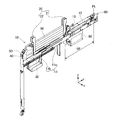
- the stick feeder 10 includes a case 11, a supply shooter 12, a component sensor 13, a guide device 20, a stick support device 30, an extrusion device 50, a component holding device 60, and an inspection device. 70 and a feeder control unit 80.
- the case 11 is formed in a flat box shape as an overall shape.
- the case 11 is configured to be extendable and contractable in the transfer direction of electronic components (Y direction in FIG. 2) in order to accommodate sticks having different lengths.
- the case 11 includes a front case portion 11a and a rear case portion 11b which are separate members.
- the front case portion 11a and the rear case portion 11b are assembled so as to be slidable with respect to each other.
- the supply shooter 12 is disposed on the front side of the case 11 (upper right side in FIG. 2).
- the supply shooter 12 is formed in a cylindrical shape and has an inner surface corresponding to the outer shape of the electronic component supplied by the stick feeder 10.
- the rear end of the supply shooter 12 is connected to the front end of the supply stick 90 ⁇ / b> A so that electronic components can be distributed.
- the supply shooter 12 constitutes a part of a guide path Sp that guides the electronic component transferred from the front end of the stick 90 to the electronic component supply position Pt.
- the component sensor 13 is provided in the supply shooter 12 and detects the presence or absence of an electronic component at a predetermined position in the supply shooter 12. When no electronic component is detected by the component sensor 13, the rearmost one row of electronic components to be transferred is positioned in front of the component sensor 13. Thereby, the feeder control unit 80 described later determines whether or not the supply stick 90A is empty based on the detection result by the component sensor 13.
- the guide device 20 is disposed on the rear side of the supply shooter 12 in the upper part of the case 11.
- the guide device 20 guides the movement in the vertical direction in a state where the plurality of sticks 90 are stacked.
- the guide device 20 includes a pair of stick guides 21 and 22.
- the front stick guide 21 is fixed to the front case portion 11 a of the case 11.
- the rear stick guide 22 is fixed to the rear case portion 11 b of the case 11. Accordingly, the pair of stick guides 21 and 22 is configured to be adjustable to an interval according to the length of the stick 90.
- the pair of stick guides 21 and 22 support the end of the stick 90 and restrict the movement of the stick 90 in the longitudinal direction and the width direction (X direction in FIG. 2).
- the guide device 20 has a pair of pins (not shown).
- the pair of pins are disposed in the pair of stick guides 21 and 22 and are provided so as to be able to advance and retract in the front-rear direction of the stick feeder 10 by an actuator.
- the pair of pins is arranged at a vertical position corresponding to the auxiliary stick 90B located on one stage of the supply stick 90A among the plurality of sticks 90.
- the pair of pins are moved into the openings at both ends of the spare stick 90B by the actuator to prevent the spare stick 90B from falling.
- the pair of pins are retracted from the openings at both ends of the spare stick 90B by the actuator, and allow the spare stick 90B to fall.
- the stick support device 30 includes a pair of support members that support both ends of the lowermost supply stick 90 (supply stick 90A) among the plurality of sticks 90.
- the front support member is disposed below the front stick guide 21 and is fixed to the case 11.
- the rear support member is disposed below the rear stick guide 22.
- the stick support device 30 has a drive device 40 that moves the support member on the rear side in the longitudinal direction of the stick 90.
- the rear support member is connected to a piston rod (not shown) of the driving device 40 and is configured to be movable by the driving device 40. Thereby, it becomes the structure which can adjust the space
- the extrusion device 50 inserts an extrusion member (not shown) from the rear end side of the supply stick 90A, and pushes out an electronic component from the front end of the supply stick 90A. Further, when the supply stick 90 ⁇ / b> A becomes empty, the extrusion device 50 further advances the extrusion member and inserts it into the supply shooter 12. Thereby, the extrusion apparatus 50 is comprised so that the electronic component in the supply shooter 12 can be transferred to the supply position Pt.
- the component holding device 60 holds the electronic component transferred to the supply position Pt so that it can be supplied. Specifically, the component holding device 60 holds the electronic component corresponding to the type of the electronic component. Thereby, the stick feeder 10 can supply various electronic components so that the component transfer device of the component mounter 1 can hold electronic components having different external shapes. Specifically, as shown in FIG. 3, the component holding device 60 includes a slide 61, a component container 62, and a detection sensor 63.
- the slide 61 of the component holding device 60 is guided in the front-rear direction (Y direction in FIG. 3) with respect to the case 11, and is configured to be capable of reciprocating between the front end of the supply shooter 12 and the supply position Pt.
- the component container 62 is a dedicated item selected corresponding to the electronic component supplied by the stick feeder 10, and is detachably connected to the upper portion of the slide 61.
- the component container 62 accommodates the first electronic component among the plurality of electronic components pushed out from the stick 90 by the extrusion device 50.
- the detection sensor 63 detects whether or not an electronic component is housed inside the component housing body 62.
- the component holding device 60 moves the component container 62 to the rear side by driving the slide 61 and connects the electronic component between the component container 62 and the supply shooter 12 so as to be able to circulate.
- the component holding device 60 recognizes that the electronic component extruded by the extrusion device 50 has been moved to a predetermined position in the component container 62 based on the detection result of the detection sensor 63. Then, the component holding device 60 moves the component container 62 to the front side by driving the slide 61, and positions the leading electronic component accommodated in the component container 62 at the supply position Pt.
- the component holding device 60 recognizes that the component transfer device of the component mounter 1 has picked up the electronic component at the supply position Pt based on the detection result of the detection sensor 63. Then, the component holding device 60 moves the component container 62 to the rear side by driving the slide 61 to reconnect the component container 62 and the supply shooter 12. As described above, the component holding device 60 constitutes a part of the guide path Sp that guides the electronic component transferred from the front end of the stick 90 to the electronic component supply position Pt.
- the inspection device 70 is provided in the guide path Sp, and inspects the state or quality of the electronic components guided in the guide path Sp.
- the inspection device 70 is provided integrally with the component holding device 60 and is unitized. The inspection device 70 inspects the state of the electronic component held by the component holding device 60. Details of the inspection apparatus 70 will be described later.
- the feeder control unit 80 controls various operations in the stick feeder 10.
- the memory of the feeder control unit 80 stores setting values such as firmware executed in electronic component supply control and the correction amount.
- the feeder control unit 80 controls the transfer operation of the extrusion device 50 and the component holding device 60 according to a command value input from the outside in a state where the feeder control unit 80 is communicably held in the slot 2a of the component supply device 2. Further, the feeder control unit 80 determines whether or not the supply stick 90 ⁇ / b> A is empty based on the detection result by the component sensor 13.
- the above-mentioned “electronic component supply control” includes control of the inspection process of the state or quality of the electronic component by the inspection device 70.
- the feeder control unit 80 includes an inspection control unit 81 that controls the inspection process of the inspection device 70.
- the inspection device 70 of the stick feeder 10 performs an inspection on an electronic component transferred through the guide path Sp.
- the electronic component supplied by the stick feeder 10 is a relay component Tr having a plurality of terminals in this embodiment.
- the relay component Tr is a latching type in which the contact is switched to a set state or a reset state by inputting a pulse current.
- the latching type relay component Tr is, for example, in a reset state and accommodated in the stick 90.
- the contact of the relay component Tr may be in a set state when vibration or impact is applied during the conveyance of the stick 90 or the like.
- operation failure may occur depending on the contact state (for example, the set state). It is assumed that the heat of the soldering process in the production line is transmitted to a specific part of the relay component Tr.
- the inspection device 70 inspects the contact state (set state / reset state) of the relay component Tr for the relay component Tr transferred to the supply position Pt.
- the inspection result by the inspection device 70 is sent from the feeder control unit 80 to the control device of the component mounting machine 1.
- the component mounter 1 determines whether to permit mounting of the supplied relay component Tr, for example, and mounts only the relay component Tr whose contact is in the reset state.
- the inspection device 70 is provided integrally with the component holding device 60 and is unitized. As shown in FIGS. 3 and 4, the inspection device 70 includes a plurality of probes 71, a lift block 72, an elevating mechanism 73, a lid member 74, and an opening / closing mechanism 75. In addition, about the operation
- the plurality of probes 71 are arranged at positions corresponding to the plurality of terminals of the relay component Tr, and are electrically connected to the corresponding terminals.
- the plurality of probes 71 are wired so as to be able to supply power to a specific terminal of the relay component Tr and to detect a conduction state.
- the lift block 72 holds a plurality of probes 71.
- the lift block 72 is guided so as to be movable in the vertical direction with respect to the slide 61.
- the elevating mechanism 73 elevates and lowers the plurality of probes 71 and the lift block 72 in the vertical direction (Z direction in FIGS. 3 and 4). Specifically, the lifting mechanism 73 lifts the lift block 72 by supplying compressed air to an air cylinder (not shown). Thereby, the raising / lowering mechanism 73 raises the several probe 71 hold
- the elevating mechanism 73 lowers the lift block 72 by cutting off the supply of compressed air to the air cylinder. As a result, the lifting mechanism 73 lowers the plurality of probes 71 held by the lift block 72 and retracts the probes 71 from the plurality of terminals of the relay component Tr to bring them into a non-contact state.
- the lid member 74 restricts the upward movement of the relay component Tr transferred to a predetermined position (in the present embodiment, the supply position Pt) of the guide path Sp.
- the opening / closing mechanism 75 moves the lid member 74 in the front-rear direction (Y direction in FIG. 3) to switch between the closed state and the open state of the lid member 74.
- the lid member 74 is in a closed state that restricts the upward movement of the relay component Tr during the inspection in which the plurality of probes 71 are in contact with the plurality of terminals of the relay component Tr.
- the lid member 74 is closed at the time of inspection when the plurality of probes 71 are raised and pressed against the plurality of terminals of the relay component Tr, and prevents the relay component Tr from jumping upward from the component holding device 60. . Further, the lid member 74 is opened after the inspection, and allows the component transfer device of the component mounter 1 to move upward so that the relay component Tr supplied by the stick feeder 10 can be picked up.
- the stick feeder 10 configured as described above performs an inspection process for the relay component Tr to be supplied, for example, during the execution of the mounting process by the component mounter 1.
- the inspection control unit 81 of the feeder control unit 80 starts inspection by the inspection device 70 after recognizing that the relay component Tr is accommodated in the component accommodating body 62 based on the detection result of the detection sensor 63.
- the inspection device 70 operates the opening / closing mechanism 75 to switch the lid member 74 to the closed state. Subsequently, the inspection apparatus 70 lifts the lift block 72 by driving the lifting mechanism 73 to bring the plurality of probes 71 into contact with the plurality of terminals of the relay component Tr. In this state, the inspection apparatus 70 performs a continuity test between the probes 71 corresponding to terminals that are conductive in the set state among the plurality of probes 71. Thereby, the state (set state / reset state) of the contact of the relay component Tr is determined based on the conduction state of the plurality of terminals.
- the inspection result by the inspection device 70 is sent to the control device of the component mounter 1 via the feeder control unit 80. Thereafter, the inspection apparatus 70 lowers the lift block 72 by driving the lifting mechanism 73 and retracts the probe from the plurality of terminals of the relay component Tr to bring it into a non-contact state. Further, the inspection device 70 operates the opening / closing mechanism 75 to switch the lid member 74 to the open state, so that the component transfer device of the component mounter 1 can pick up the relay component Tr.
- the component mounter 1 picks up the relay component Tr by the component transfer device after the relay component Tr is positioned at the supply position Pt by the component holding device 60 and the inspection by the inspection device 70 is completed.
- the component mounter 1 determines whether or not to permit mounting of the relay component Tr based on the inspection result regarding the relay component Tr.
- the component mounter 1 permits mounting of the relay component Tr on the circuit board when the contact is in the reset state. On the other hand, when the contact is in the set state, the component mounter 1 discards the relay component Tr, for example.
- the stick feeder 10 inspects the contact state (set state / reset state) of the relay component Tr by the inspection device 70.
- the stick feeder 10 further includes a switching device 170 that supplies power to a terminal to which power is supplied when operating the contact among the plurality of terminals of the relay component Tr, and sets the contact to a predetermined state (for example, a reset state). It is good also as a structure provided (refer FIG. 6).
- the switching device 170 can employ the same mechanical configuration as the inspection device 70 exemplified in the embodiment. Therefore, description of the detailed configuration of the switching device 170 is omitted.
- the switching device 170 is controlled in switching processing by the switching control unit 182 of the feeder control unit 80. Specifically, the switching device 170 of the stick feeder 10 supplies power via a probe 71 to a terminal to which a pulse current is input, for example, when the contact is switched to a reset state. Thereby, the contact of the relay component Tr is switched to the reset state. After that, the stick feeder 10 executes the inspection process again by the inspection device 70 and inspects whether the contact is actually in a reset state.
- the inspection result by the inspection device 70 is sent to the control device of the component mounter 1 via the feeder control unit 80.
- the component mounter 1 picks up the relay component Tr by the component transfer device, and when the contact of the relay component Tr is not in the reset state based on the inspection result, the relay component Tr is regarded as a defective component that cannot switch the contact state. Discard.
- the inspection device 70 of the stick feeder 10 may perform a quality test regarding the quality of the relay component Tr in addition to or instead of the status test regarding the contact status (set state / reset status) of the relay component Tr. Specifically, the relay component Tr is actually operated in the same manner as the switching of the contacts, and a continuity test is performed for each contact state. Thereby, based on the conduction
- the electronic component to be inspected is a latching type relay component Tr.
- the inspection device 70 is an electronic component supplied by the stick feeder 10, a normal relay component whose contact state is switched only during power feeding, and other electronic components such as a capacitor, a fuse, and a resistor. Can be the inspection target. Similarly, when these electronic components are inspected, state inspection and pass / fail inspection can be performed.
- the inspection device 70 is configured to be provided integrally with the component holding device 60.
- the inspection device 70 can be appropriately disposed between the front end position of the stick 90 and the supply position Pt as long as the inspection apparatus 70 is configured in the guide path Sp of the stick feeder 10.
- an inspection device 70 may be disposed in the middle portion of the supply shooter 12 and a plurality of probes 71 may inspect electronic components.
- the opening / closing mechanism 75 of the lid member 74 can be omitted.
- the stick feeder 10 may further include a mechanism for discarding the electronic component from the component holding device 60 when it is determined that the electronic component is defective based on the result of the inspection by the inspection device 70. .
- the component supply device 2 can discard and supply an appropriate electronic component, so that the efficiency of the mounting process can be improved.
- the stick feeder 10 employs a drop type in which the stacked spare sticks 90 are dropped and replenished as new supply sticks 90.
- the stick feeder 10 can employ an inclined type that holds the stacked sticks 90 in an inclined manner. Even in such a configuration, the inspection apparatus 70 can be applied as in the embodiment.
- the stick feeder 10 is configured to include an inspection device 70 that inspects the contact state of the relay component Tr.
- the stick feeder 10 may be configured to include a switching device 170 that switches the contact state of the relay component Tr guided along the guide path Sp instead of the inspection device 70 (see FIG. 6).
- the switching device 170 supplies power to a terminal to which power is supplied when operating the contact among the plurality of terminals of the relay component Tr, thereby bringing the contact into a predetermined state.
- the stick feeder 10 does not perform inspection, and therefore supplies a pulse current for setting a reset state, for example, to a predetermined terminal regardless of the contact state of the relay component Tr to be supplied. Thereby, the contact of the relay component Tr is switched to the reset state in the set state and the reset state is maintained in the reset state from the beginning without executing the inspection process.
- the stick feeder 10 pushes out an electronic component from the front end of the stick 90 that houses a plurality of electronic components (relay components Tr), and supplies the electronic components.
- the stick feeder 10 is provided with a guide path Sp that guides an electronic component that is transferred from the front end of the stick 90 to the electronic component supply position Pt, and a state or pass / fail of the electronic component that is provided in the guide path Sp and guided to the guide path Sp.
- an inspection device 70 for inspecting.
- the electronic component (relay component Tr) transported inside the stick feeder 10 can be inspected for the state or quality of the electronic component. Accordingly, the component mounter 1 can determine whether to mount or discard the electronic component based on the inspection result in the mounting process. Accordingly, inappropriate mounting of electronic components on the circuit board is prevented, and as a result, the defect occurrence rate of the circuit board product can be reduced.
- the electronic component is a relay component Tr having a plurality of terminals.
- the inspection device 70 inspects the state of the contact of the relay component Tr or the quality of the operation. According to such a configuration, it is possible to inspect the contact state of the relay component Tr or the quality of the operation for the relay component Tr.
- the inspection for the relay component Tr is particularly useful with the above configuration.
- the inspection device 70 inspects the contact state of the relay component Tr based on the conduction states of the plurality of terminals. According to such a configuration, the inspection device 70 performs a continuity test on the relay component Tr to inspect the contact state. Thereby, since the state of the contact of the relay component Tr can be reliably recognized, the component mounter 1 can reflect the result of the inspection in the mounting process. Therefore, the defect occurrence rate of circuit board products can be reduced.
- the stick feeder 10 is further provided with the switching apparatus which supplies electric power to the terminal electrically supplied when operating a contact among several terminals, and makes a contact a predetermined state.
- the contact of the relay component Tr to be supplied can be switched to a predetermined state.
- the electronic component (relay component Tr) has a plurality of terminals extending downward.
- the inspection apparatus 70 includes a plurality of probes 71 that are electrically connected to a plurality of terminals, a plurality of probes 71 that are raised and brought into contact with the plurality of terminals, and a plurality of probes 71 that are lowered and retracted from the plurality of terminals. And an elevating mechanism 73 to be moved, and a lid member 74 for restricting the upward movement of the electronic component (relay component Tr) transferred to a predetermined position of the guide path Sp.
- a continuity test via the probe 71 can be executed with a configuration corresponding to a plurality of terminals of the electronic component (relay component Tr).
- the plurality of probes 71 can be protruded or retracted from the guide path Sp, it is possible to reliably prevent the plurality of probes 71 from interfering with the transfer of the electronic component before and after the execution of the inspection.
- the vertical position of the plurality of probes 71 can be controlled by the operation of the elevating mechanism 73 in correspondence with the tip positions of the terminals having individual differences, it is possible to improve the accuracy of the inspection.
- the stick feeder 10 further includes a component holding device 60 that forms a part of the guide path Sp and holds the electronic component (relay component Tr) transferred to the supply position Pt so as to be supplied.
- the inspection device 70 is provided integrally with the component holding device 60. According to such a configuration, the inspection by the inspection device 70 is performed on the foremost electronic component among a plurality of electronic components (relay components Tr) arranged in the longitudinal direction of the stick 90. Thereby, it is possible to inspect the electronic component immediately before being supplied.
- the inspection device 70 is provided integrally with the component holding device 60 and is unitized, the electronic component can be supplied and inspected by effectively using the space at the tip of the stick feeder 10.
- the lid member 74 is in a closed state that restricts the upward movement of the electronic component when inspecting the electronic component (relay component Tr) in which the plurality of probes 71 are in contact with the plurality of terminals.
- the electronic component is supplied by the component holding device 60, it is opened.
- the lid member 74 since the lid member 74 is in the open state, the lid member 74 can be prevented from hindering supply of electronic components after the inspection.
- the stick feeder 10 pushes out an electronic component from the front end of a stick 90 that houses a plurality of electronic components, and supplies the electronic component.
- the electronic component (relay component Tr) is a relay component Tr having a plurality of terminals.
- the stick feeder 10 is a switching device that switches between a guide path Sp that guides the relay part Tr that is transferred from the front end of the stick 90 to the supply position Pt of the relay part Tr and a contact state of the relay part Tr that is guided to the guide path Sp. And comprising.
- the switching device supplies power to a terminal to which power is supplied when operating the contact among the plurality of terminals, thereby bringing the contact into a predetermined state.
- the contact of the relay component Tr can be switched to a predetermined state for the relay component Tr transferred inside the stick feeder 10.
- a normal relay component Tr is affected by the soldering process in the production line, depending on the state of the contact, and causes malfunction. Therefore, by uniformly setting the contacts of the relay component Tr to be supplied to a predetermined state with the above-described configuration, it is possible to reduce the influence of subsequent processes on the relay component Tr and the circuit board product. The defect occurrence rate can be reduced.
Landscapes
- Engineering & Computer Science (AREA)
- Manufacturing & Machinery (AREA)
- Microelectronics & Electronic Packaging (AREA)
- Supply And Installment Of Electrical Components (AREA)
Abstract
実装前の電子部品を対象とした検査を可能として、回路基板製品の不良発生率を低減できるスティックフィーダを提供することを目的とする。スティックフィーダは、複数の電子部品を収容するスティックの前端から電子部品を押し出して、当該電子部品を供給する。スティックフィーダ(10)は、スティックの前端から電子部品の供給位置まで移送される電子部品を案内する案内路と、案内路に設けられ、案内路に案内された電子部品の状態または良否を検査する検査装置と、を備える。
Description
本発明は、スティックフィーダに関するものである。
スティックフィーダは、電子部品を基板に実装する部品実装機に用いられる。特許文献1には、複数の電子部品を収容するスティックの前端から電子部品を押し出して、当該電子部品を供給するスティックフィーダが開示されている。また、部品実装機は、例えば集積回路などの回路基板製品を製造する生産ラインを構成する。
部品実装機による実装処理において、例えば供給される電子部品に不良があると、正常に動作しない回路基板製品が製造されるおそれがある。そのため、生産ラインには、製造される回路基板製品の不良発生率の低減が望まれている。
本発明は、このような事情に鑑みてなされたものであり、実装前の電子部品を対象とした検査を可能として、回路基板製品の不良発生率を低減できるスティックフィーダを提供することを目的とする。
請求項1に係るスティックフィーダは、複数の電子部品を収容するスティックの前端から前記電子部品を押し出して、当該電子部品を供給する。スティックフィーダは、前記スティックの前端から前記電子部品の供給位置まで移送される前記電子部品を案内する案内路と、前記案内路に設けられ、前記案内路に案内された前記電子部品の状態または良否を検査する検査装置と、を備える。
請求項8に係るスティックフィーダは、複数の電子部品を収容するスティックの前端から前記電子部品を押し出して、当該電子部品を供給する。前記電子部品は、複数の端子を有するリレー部品である。スティックフィーダは、前記スティックの前端から前記リレー部品の供給位置まで移送される前記リレー部品を案内する案内路と、前記案内路に案内された前記リレー部品の接点の状態を切り換える切換装置と、を備える。前記切換装置は、前記複数の端子のうち前記接点を動作させる際に給電される前記端子に給電して、前記接点を所定の状態とする。
請求項1に係る発明の構成によると、スティックフィーダの内部において移送されている電子部品を対象として、当該電子部品の状態または良否を検査することが可能となる。これにより、部品実装機は、実装処理において、検査結果に基づいて、当該電子部品を実装するか廃棄するかを判断できる。よって、回路基板への不適な電子部品の実装が防止されるので、結果として回路基板製品の不良発生率を低減できる。
請求項8に係る発明の構成によると、スティックフィーダの内部において移送されているリレー部品を対象として、当該リレー部品の接点が所定の状態に切り換えることが可能となる。ここで、正常なリレー部品であっても接点の状態によっては、生産ラインにおけるはんだ付け工程などに影響されて、動作不良を生じることが見出された。そこで、上記のような構成により、供給するリレー部品の接点を一律に所定の状態とすることによって、後工程がリレー部品や回路基板製品に与える影響を低減できるので、結果として回路基板製品の不良発生率を低減できる。
以下、本発明のスティックフィーダを具体化した実施形態について図面を参照して説明する。スティックフィーダは、部品実装機の部品供給装置を構成する。スティックフィーダは、複数の電子部品を収容するスティックの前端から電子部品を押し出して、当該電子部品を供給する。上記の部品実装機は、スティックフィーダにより供給された電子部品を保持部材により保持して、この電子部品を回路基板上の所定位置に装着する装置である。
<実施形態>
(スティックフィーダ10の概要)
スティックフィーダ10は、図1に示すように、部品実装機1の部品供給装置2のスロット2aに着脱可能にセットされる。セットされたスティックフィーダ10は、部品実装機1の本体から電力を供給されるとともに、部品実装機1の制御装置と通信可能な状態となる。スティックフィーダ10は、図2に示すように、複数のスティック90を積み上げた状態で支持する。
(スティックフィーダ10の概要)
スティックフィーダ10は、図1に示すように、部品実装機1の部品供給装置2のスロット2aに着脱可能にセットされる。セットされたスティックフィーダ10は、部品実装機1の本体から電力を供給されるとともに、部品実装機1の制御装置と通信可能な状態となる。スティックフィーダ10は、図2に示すように、複数のスティック90を積み上げた状態で支持する。
なお、本実施形態において、スティックフィーダ10は、スティック90を水平の姿勢で支持する。また、スティックフィーダ10は、供給用のスティック90が空となった場合に下方に落下させて排出する。そして、スティックフィーダ10は、積み上げられた予備のスティック90を落下させて、新たな供給用のスティック90として補給する落下型を採用する。
(スティック90の構成)
スティック90は、直線状の本体内に電子部品が1列に並べて収容する。スティック90の両端は、長手方向に開口するように形成されている。ここで、スティック90がスティックフィーダ10に支持された状態において、電子部品の供給側(図2の右上側)を前側、電子部品の反供給側(図2の左下側)を後側とする。スティック90は、後述する押出装置50により電子部品を押し出され、スティック90の前端から電子部品を排出する。
スティック90は、直線状の本体内に電子部品が1列に並べて収容する。スティック90の両端は、長手方向に開口するように形成されている。ここで、スティック90がスティックフィーダ10に支持された状態において、電子部品の供給側(図2の右上側)を前側、電子部品の反供給側(図2の左下側)を後側とする。スティック90は、後述する押出装置50により電子部品を押し出され、スティック90の前端から電子部品を排出する。
以下では、積み上げられた複数のスティック90のうち最下段に位置して、使用中にある供給用のスティック90を供給用スティック90Aとも称する。また、供給用スティック90Aに積み上げられた予備のスティック90を予備スティック90Bとも称する。
(スティックフィーダ10の全体構成)
スティックフィーダ10は、図2に示すように、ケース11と、供給シュータ12と、部品センサ13と、ガイド装置20と、スティック支持装置30と、押出装置50と、部品保持装置60と、検査装置70と、フィーダ制御部80とを備えて構成される。
スティックフィーダ10は、図2に示すように、ケース11と、供給シュータ12と、部品センサ13と、ガイド装置20と、スティック支持装置30と、押出装置50と、部品保持装置60と、検査装置70と、フィーダ制御部80とを備えて構成される。
ケース11は、全体形状としては扁平な箱形状に形成される。ケース11は、長さの異なるスティックに対応するために、電子部品の移送方向(図2のY方向)に伸縮可能に構成される。具体的には、ケース11は、別部材である前側ケース部11aおよび後側ケース部11bにより構成される。前側ケース部11aおよび後側ケース部11bは、互いにスライド可能に組み付けられている。
供給シュータ12は、ケース11の前側(図2の右上側)の上部に配置される。供給シュータ12は、筒状に形成され、スティックフィーダ10により供給される電子部品の外形に対応した内面を有する。供給シュータ12の後端は、供給用スティック90Aの前端との間で電子部品を流通可能に連結される。供給シュータ12は、スティック90の前端から電子部品の供給位置Ptまで移送される電子部品を案内する案内路Spの一部を構成する。
部品センサ13は、供給シュータ12に設けられ、供給シュータ12内の所定位置における電子部品の有無を検出する。部品センサ13により電子部品が検出されない場合には、移送される1列の電子部品の最後尾が部品センサ13よりも前側に位置することになる。これにより、後述するフィーダ制御部80は、部品センサ13による検出結果に基づいて、供給用スティック90Aが空か否かを判定する。
ガイド装置20は、ケース11の上部において供給シュータ12の後側に配置される。ガイド装置20は、複数のスティック90を積み上げた状態で上下方向に移動を案内する。このガイド装置20は、一対のスティックガイド21,22を有する。前側のスティックガイド21は、ケース11の前側ケース部11aに固定される。後側のスティックガイド22は、ケース11の後側ケース部11bに固定される。これにより、一対のスティックガイド21,22は、スティック90の長さに応じた間隔に調整可能に構成される。一対のスティックガイド21,22は、スティック90の端部を支持して、スティック90の長手方向および幅方向(図2のX方向)の移動を規制する。
また、ガイド装置20は、図示しない一対のピンを有する。一対のピンは、一対のスティックガイド21,22に配置され、アクチュエータによってスティックフィーダ10の前後方向に進退可能に設けられる。一対のピンは、複数のスティック90のうち供給用スティック90Aの一段上に位置する予備スティック90Bに対応する上下方向位置に配置される。一対のピンは、アクチュエータにより予備スティック90Bの両端の開口へと進入されて、当該予備スティック90Bの落下を防止する。また、一対のピンは、アクチュエータにより予備スティック90Bの両端の開口から退避されて、当該予備スティック90Bの落下を許容する。
スティック支持装置30は、複数のスティック90のうち最下段の供給用のスティック90(供給用スティック90A)の両端を支持する一対の支持部材を有する。前側の支持部材は、前側のスティックガイド21の下方に配置され、ケース11に固定される。後側の支持部材は、後側のスティックガイド22の下方に配置される。
また、スティック支持装置30は、後側の支持部材をスティック90の長手方向に移動させる駆動装置40を有する。後側の支持部材は、駆動装置40のピストンロッド(図示しない)に連結され、駆動装置40により移動可能に構成される。これにより、一対の支持部材の間隔が調整可能な構成となっている。
押出装置50は、供給用スティック90Aの後端側から図示しない押出部材を挿入して、供給用スティック90Aの前端から電子部品を押し出す。また、押出装置50は、供給用スティック90Aが空になった場合に、押出部材をさらに進出させて供給シュータ12に挿入する。これにより、押出装置50は、供給シュータ12内の電子部品を供給位置Ptまで移送可能に構成される。
部品保持装置60は、供給位置Ptまで移送された電子部品を供給可能に保持する。詳細には、部品保持装置60は、電子部品の種類に対応して当該電子部品を保持する。これにより、スティックフィーダ10は、外形の異なる電子部品を部品実装機1の部品移載装置が保持できるように、種々の電子部品に対応した供給が可能となる。具体的には、部品保持装置60は、図3に示すように、スライド61と、部品収容体62と、検出センサ63とを有する。
部品保持装置60のスライド61は、ケース11に対して前後方向(図3のY方向)に案内され、供給シュータ12の前端と供給位置Ptとの間を往復移動可能に構成される。部品収容体62は、スティックフィーダ10が供給する電子部品に対応して選択された専用品であり、スライド61の上部に着脱可能に連結される。部品収容体62は、押出装置50によりスティック90から押し出された複数の電子部品のうち先頭の電子部品を収容する。検出センサ63は、部品収容体62の内部に電子部品が収容されているか否かを検出する。
部品保持装置60は、スライド61の駆動により部品収容体62を後側に移動させて、部品収容体62と供給シュータ12との間で電子部品を流通可能に連結させる。部品保持装置60は、押出装置50により押し出された電子部品が部品収容体62内の所定位置まで移動されたことを検出センサ63の検出結果に基づいて認識する。そして、部品保持装置60は、スライド61の駆動により部品収容体62を前側に移動させて、部品収容体62に収容された先頭の電子部品を供給位置Ptに位置決めする。
部品保持装置60は、検出センサ63の検出結果に基づいて、部品実装機1の部品移載装置が供給位置Ptにある電子部品をピックアップしたことを認識する。そして、部品保持装置60は、スライド61の駆動により部品収容体62を後側に移動させて、部品収容体62と供給シュータ12とを再び連結させる。上記のように、部品保持装置60は、スティック90の前端から電子部品の供給位置Ptまで移送される電子部品を案内する案内路Spの一部を構成する。
検査装置70は、案内路Spに設けられ、案内路Spに案内された電子部品の状態または良否を検査する。検査装置70は、本実施形態において、部品保持装置60に一体的に設けられ、ユニット化される。検査装置70は、部品保持装置60により保持された電子部品の状態を検査する。検査装置70の詳細については後述する。
フィーダ制御部80は、スティックフィーダ10における種々の動作を制御する。フィーダ制御部80のメモリには、電子部品の供給制御などにおいて実行されるファームウェアや補正量などの設定値が記憶されている。フィーダ制御部80は、部品供給装置2のスロット2aに通信可能に保持された状態において、外部入力される指令値に応じて押出装置50や部品保持装置60の移送動作を制御する。また、フィーダ制御部80は、部品センサ13による検出結果に基づいて、供給用スティック90Aが空か否かを判定する。
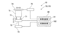
なお、本実施形態において、上記の「電子部品の供給制御」には、検査装置70による電子部品の状態または良否の検査処理の制御が含まれる。フィーダ制御部80は、図5に示すように、検査装置70の検査処理を制御する検査制御部81を有する。
(検査装置70の詳細構成)
スティックフィーダ10の検査装置70は、案内路Spを移送される電子部品を対象として検査を行う。なお、スティックフィーダ10により供給される電子部品は、本実施形態において、複数の端子を有するリレー部品Trとする。詳細には、リレー部品Trは、パルス電流の入力によって接点がセット状態またはリセット状態に切り換えられるラッチング型である。
スティックフィーダ10の検査装置70は、案内路Spを移送される電子部品を対象として検査を行う。なお、スティックフィーダ10により供給される電子部品は、本実施形態において、複数の端子を有するリレー部品Trとする。詳細には、リレー部品Trは、パルス電流の入力によって接点がセット状態またはリセット状態に切り換えられるラッチング型である。
ラッチング型のリレー部品Trは、例えばリセット状態とされてスティック90に収容される。しかしながら、スティック90の搬送時などに振動や衝撃が加えられた場合に、リレー部品Trの接点がセット状態になっていることがある。このように、リレー部品Trが機能的に正常であっても接点の状態(例えばセット状態)によっては、動作不良を生じることが見出された。これは、生産ラインにおけるはんだ付け工程の熱がリレー部品Trの特定部位に伝達されることなどが想定される。
そこで、検査装置70は、供給位置Ptまで移送されたリレー部品Trを対象として、当該リレー部品Trの接点の状態(セット状態/リセット状態)を検査する。検査装置70による検査結果は、フィーダ制御部80より部品実装機1の制御装置に送出される。部品実装機1は、当該検査結果に基づいて、例えば供給されたリレー部品Trの実装を許可するか否かを判定し、接点がリセット状態にあるリレー部品Trのみを実装する。
検査装置70は、本実施形態において、図3に示すように、部品保持装置60に一体的に設けられ、ユニット化されている。検査装置70は、図3および図4に示すように、複数のプローブ71と、リフトブロック72と、昇降機構73と、蓋部材74と、開閉機構75とを有する。なお、検査装置70の各機構の動作については、フィーダ制御部80の検査制御部81が統括する(図5を参照)。
複数のプローブ71は、リレー部品Trの複数の端子に対応する位置に配置され、対応する端子に電気的に接続される。複数のプローブ71は、リレー部品Trの特定の端子に給電可能に、また導通状態を検出可能に配線される。リフトブロック72は、複数のプローブ71を保持する。リフトブロック72は、スライド61に対して上下方向に移動可能にガイドされている。
昇降機構73は、複数のプローブ71およびリフトブロック72を上下方向(図3および図4のZ方向)に昇降する。詳細には、昇降機構73は、図示しないエアシリンダに圧縮エアを供給することによりリフトブロック72を持ち上げる。これにより、昇降機構73は、リフトブロック72に保持された複数のプローブ71を上昇させて、リレー部品Trの複数の端子にそれぞれ対応するプローブ71を接触させる。
また、昇降機構73は、エアシリンダへの圧縮エアの供給を遮断することによりリフトブロック72を下降させる。これにより、昇降機構73は、リフトブロック72に保持された複数のプローブ71を下降させて、リレー部品Trの複数の端子からプローブ71を退避させて非接触の状態とする。
蓋部材74は、案内路Spの所定位置(本実施形態においては、供給位置Pt)に移送されたリレー部品Trの上方移動を規制する。開閉機構75は、蓋部材74を前後方向(図3のY方向)に移動させて、蓋部材74の閉状態と開状態とを切り換える。蓋部材74は、リレー部品Trの複数の端子に複数のプローブ71が接触された検査時には、リレー部品Trの上方移動を規制する閉状態とされる。
つまり、蓋部材74は、複数のプローブ71が上昇されてリレー部品Trの複数の端子に押し付けられた検査時に閉状態とされて、リレー部品Trが部品保持装置60から上方に飛び出すことを防止する。また、蓋部材74は、検査後に開状態とされ、部品実装機1の部品移載装置がスティックフィーダ10により供給されたリレー部品Trをピックアップできるように上方移動を許容する。
(検査装置70による検査処理)
上記のような構成からなるスティックフィーダ10は、例えば部品実装機1による実装処理の実行中において、供給するリレー部品Trを対象とした検査処理を実行する。フィーダ制御部80の検査制御部81は、検出センサ63の検出結果に基づいて部品収容体62の内部にリレー部品Trが収容されたことを認識した後に、検査装置70による検査を開始する。
上記のような構成からなるスティックフィーダ10は、例えば部品実装機1による実装処理の実行中において、供給するリレー部品Trを対象とした検査処理を実行する。フィーダ制御部80の検査制御部81は、検出センサ63の検出結果に基づいて部品収容体62の内部にリレー部品Trが収容されたことを認識した後に、検査装置70による検査を開始する。
検査装置70は、先ず、開閉機構75を動作させて蓋部材74を閉状態に切り換える。続いて、検査装置70は、昇降機構73の駆動によってリフトブロック72を持ち上げて、複数のプローブ71をリレー部品Trの複数の端子に接触させる。この状態で、検査装置70は、複数のプローブ71のうちセット状態において導通する端子に対応するプローブ71間の導通試験を行う。これにより、複数の端子の導通状態に基づいて、リレー部品Trの接点の状態(セット状態/リセット状態)が判定される。
検査装置70による検査結果は、フィーダ制御部80を介して部品実装機1の制御装置に送出される。その後に、検査装置70は、昇降機構73の駆動によってリフトブロック72を下降させて、リレー部品Trの複数の端子からプローブを退避させて非接触の状態とする。さらに、検査装置70は、開閉機構75を動作させて蓋部材74を開状態に切り換えて、部品実装機1の部品移載装置がリレー部品Trをピックアップ可能な状態とする。
部品実装機1は、部品保持装置60によりリレー部品Trが供給位置Ptに位置決めされ、且つ検査装置70による検査が完了した後に、部品移載装置によりリレー部品Trをピックアップする。部品実装機1は、当該リレー部品Trに関する検査結果に基づいて、リレー部品Trの実装を許可するか否かを判定する。部品実装機1は、接点がリセット状態の場合には、回路基板への当該リレー部品Trの実装を許可する。一方で、部品実装機1は、接点がセット状態の場合には、例えば当該リレー部品Trを廃棄する。
<実施形態の変形態様>
(切換装置について)
実施形態において、スティックフィーダ10は、検査装置70によりリレー部品Trの接点の状態(セット状態/リセット状態)を検査する。ここで、スティックフィーダ10は、リレー部品Trの複数の端子のうち接点を動作させる際に給電される端子に給電をして、接点を所定の状態(例えばリセット状態)とする切換装置170をさらに備える構成としてもよい(図6を参照)。
(切換装置について)
実施形態において、スティックフィーダ10は、検査装置70によりリレー部品Trの接点の状態(セット状態/リセット状態)を検査する。ここで、スティックフィーダ10は、リレー部品Trの複数の端子のうち接点を動作させる際に給電される端子に給電をして、接点を所定の状態(例えばリセット状態)とする切換装置170をさらに備える構成としてもよい(図6を参照)。
切換装置170は、実施形態にて例示した検査装置70と同様の機械構成を採用することができる。そのため、切換装置170の詳細構成については説明を省略する。切換装置170は、フィーダ制御部80の切換制御部182により切換処理を制御される。具体的には、スティックフィーダ10の切換装置170は、例えば接点をリセット状態に切り換える際にパルス電流を入力される端子にプローブ71を介して給電する。これにより、リレー部品Trの接点は、リセット状態に切り換えられる。その後に、スティックフィーダ10は、検査装置70により再度の検査処理を実行し、実際に接点がリセット状態となっているかを検査する。
検査装置70による検査結果は、フィーダ制御部80を介して部品実装機1の制御装置に送出される。部品実装機1は、部品移載装置によりリレー部品Trをピックアップし、検査結果により当該リレー部品Trの接点がリセット状態でない場合には、接点の状態を切り換えることができない不良部品として当該リレー部品Trを廃棄する。
(検査対象について)
スティックフィーダ10の検査装置70は、リレー部品Trの接点の状態(セット状態/リセット状態)に関する状態検査に加えてまたは換えて、リレー部品Trの良否に関する良否検査を行ってもよい。具体的には、上記の接点の切り換えと同様にリレー部品Trを実際に動作させて、それぞれの接点の状態における導通試験を行う。これにより、複数の端子の導通状態に基づいて、リレー部品Trの接点の状態および良否が検査される。
スティックフィーダ10の検査装置70は、リレー部品Trの接点の状態(セット状態/リセット状態)に関する状態検査に加えてまたは換えて、リレー部品Trの良否に関する良否検査を行ってもよい。具体的には、上記の接点の切り換えと同様にリレー部品Trを実際に動作させて、それぞれの接点の状態における導通試験を行う。これにより、複数の端子の導通状態に基づいて、リレー部品Trの接点の状態および良否が検査される。
また、実施形態において、検査対象の電子部品は、ラッチング型のリレー部品Trであるものとした。これに対して、検査装置70は、スティックフィーダ10により供給される電子部品であれば、給電時にのみ接点の状態が切り換えられる通常型のリレー部品や、その他のコンデンサやヒューズ、抵抗などの電子部品を検査対象とすることができる。また、これらの電子部品を検査対象とした場合も同様に、状態検査や良否検査を行うことができる。
(その他)
実施形態において、検査装置70は、部品保持装置60と一体的に設けられる構成とした。これに対して、検査装置70は、スティックフィーダ10の案内路Spに設けられる構成であれば、スティック90の前端位置から供給位置Ptまでの間に適宜配置することができる。例えば、供給シュータ12の中間部に検査装置70を配置し、複数のプローブ71により電子部品を検査する構成としてもよい。このとき、供給シュータ12の中間部においては、供給シュータ12の上壁によって電子部品の上方移動が規制されているため、蓋部材74の開閉機構75を省略することができる。
実施形態において、検査装置70は、部品保持装置60と一体的に設けられる構成とした。これに対して、検査装置70は、スティックフィーダ10の案内路Spに設けられる構成であれば、スティック90の前端位置から供給位置Ptまでの間に適宜配置することができる。例えば、供給シュータ12の中間部に検査装置70を配置し、複数のプローブ71により電子部品を検査する構成としてもよい。このとき、供給シュータ12の中間部においては、供給シュータ12の上壁によって電子部品の上方移動が規制されているため、蓋部材74の開閉機構75を省略することができる。
また、スティックフィーダ10は、検査装置70による検査の結果に基づいて、電子部品が不良であるものと判定した場合に、当該電子部品を部品保持装置60から廃棄する機構をさらに備える構成としてもよい。これにより、部品実装機1の部品移載装置の動作によらず、部品供給装置2において廃棄および適正な電子部品の供給を行うことができるので、実装処理の効率化を図ることができる。
また、実施形態において、スティックフィーダ10は、積み上げられた予備のスティック90を落下させて、新たな供給用のスティック90として補給する落下型を採用した。これに対して、スティックフィーダ10は、積み上げられた複数のスティック90を傾斜させて保持する傾斜型を採用することも可能である。このような構成においても実施形態と同様に、検査装置70を適用することができる。
実施形態において、スティックフィーダ10は、リレー部品Trの接点の状態を検査する検査装置70を備える構成とした。これに対して、スティックフィーダ10は、検査装置70に換えて、案内路Spに案内されたリレー部品Trの接点の状態を切り換える切換装置170を備える構成としてもよい(図6を参照)。切換装置170は、リレー部品Trの複数の端子のうち接点を動作させる際に給電される端子に給電して、接点を所定の状態とする。
このような構成によると、スティックフィーダ10は、検査を行わないので、供給するリレー部品Trの接点の状態によらずに、例えばリセット状態とするためのパルス電流を所定の端子に給電する。これにより、検査処理を実行されることなく、リレー部品Trの接点は、セット状態の場合にはリセット状態に切り換えられ、当初からリセット状態の場合にはリセット状態が維持される。
<実施形態および変形態様による効果>
スティックフィーダ10は、複数の電子部品(リレー部品Tr)を収容するスティック90の前端から電子部品を押し出して、当該電子部品を供給する。スティックフィーダ10は、スティック90の前端から電子部品の供給位置Ptまで移送される電子部品を案内する案内路Spと、案内路Spに設けられ、案内路Spに案内された電子部品の状態または良否を検査する検査装置70と、を備える。
スティックフィーダ10は、複数の電子部品(リレー部品Tr)を収容するスティック90の前端から電子部品を押し出して、当該電子部品を供給する。スティックフィーダ10は、スティック90の前端から電子部品の供給位置Ptまで移送される電子部品を案内する案内路Spと、案内路Spに設けられ、案内路Spに案内された電子部品の状態または良否を検査する検査装置70と、を備える。
このような構成によると、スティックフィーダ10の内部において移送されている電子部品(リレー部品Tr)を対象として、当該電子部品の状態または良否を検査することが可能となる。これにより、部品実装機1は、実装処理において、検査結果に基づいて、当該電子部品を実装するか廃棄するかなどを判断できる。よって、回路基板への不適な電子部品の実装が防止されるので、結果として回路基板製品の不良発生率を低減できる。
また、電子部品は、複数の端子を有するリレー部品Trである。検査装置70は、リレー部品Trの接点の状態、または動作の良否を検査する。
このような構成によると、リレー部品Trを対象として、当該リレー部品Trの接点の状態、または動作の良否を検査することができる。ここで、正常なリレー部品Trであっても接点の状態によっては、生産ラインにおけるはんだ付け工程などに影響されて、動作不良を生じることが見出された。そこで、上記のような構成により、リレー部品Trを対象とした検査は特に有用である。
このような構成によると、リレー部品Trを対象として、当該リレー部品Trの接点の状態、または動作の良否を検査することができる。ここで、正常なリレー部品Trであっても接点の状態によっては、生産ラインにおけるはんだ付け工程などに影響されて、動作不良を生じることが見出された。そこで、上記のような構成により、リレー部品Trを対象とした検査は特に有用である。
また、検査装置70は、複数の端子の導通状態に基づいて、リレー部品Trの接点の状態を検査する。
このような構成によると、検査装置70は、リレー部品Trを対象とした導通試験を行って、接点の状態を検査する。これにより、リレー部品Trの接点の状態を確実に認識することができるので、部品実装機1は、当該検査の結果を実装処理に反映できる。よって、回路基板製品の不良発生率を低減できる。
このような構成によると、検査装置70は、リレー部品Trを対象とした導通試験を行って、接点の状態を検査する。これにより、リレー部品Trの接点の状態を確実に認識することができるので、部品実装機1は、当該検査の結果を実装処理に反映できる。よって、回路基板製品の不良発生率を低減できる。
また、変形態様において、スティックフィーダ10は、複数の端子のうち接点を動作させる際に給電される端子に給電して、接点を所定の状態とする切換装置をさらに備える。
このような構成によると、供給するリレー部品Trの接点を所定の状態に切り換えることが可能となる。これにより、はんだ付け工程などの後工程が電子部品や回路基板製品に与える影響を低減できるので、結果として回路基板製品の不良発生率を低減できる。
このような構成によると、供給するリレー部品Trの接点を所定の状態に切り換えることが可能となる。これにより、はんだ付け工程などの後工程が電子部品や回路基板製品に与える影響を低減できるので、結果として回路基板製品の不良発生率を低減できる。
また、電子部品(リレー部品Tr)は、下方に延びる複数の端子を有する。検査装置70は、複数の端子に電気的に接続される複数のプローブ71と、複数のプローブ71を上昇させて複数の端子に接触させるとともに、複数のプローブ71を下降させて複数の端子から退避させる昇降機構73と、案内路Spの所定位置に移送された電子部品(リレー部品Tr)の上方移動を規制する蓋部材74と、をさらに有する。
このような構成によると、電子部品(リレー部品Tr)の複数の端子に対応した構成により、プローブ71介した導通試験を実行することができる。また、複数のプローブ71を案内路Spに対して突起させたり退避させたりすることができるので、検査の実行前後においては、電子部品の移送を複数のプローブ71が妨げることを確実に防止できる。さらに、昇降機構73の動作によって、個体差のある端子の先端位置に対応して複数のプローブ71の上下方向位置を制御できるので、検査の高精度化を図ることができる。
また、スティックフィーダ10は、案内路Spの一部を構成し、且つ供給位置Ptまで移送された電子部品(リレー部品Tr)を供給可能に保持する部品保持装置60をさらに備える。検査装置70は、部品保持装置60に一体的に設けられる。
このような構成によると、検査装置70による検査は、スティック90の長手方向に並んだ複数の電子部品(リレー部品Tr)のうち最前の電子部品を対象として行われる。これにより、供給される直前の電子部品を対象として検査をすることができる。また、検査装置70が部品保持装置60に一体的に設けられてユニット化されることにより、スティックフィーダ10の先端部のスペースを有効利用して、電子部品の供給および検査を行うことができる。
このような構成によると、検査装置70による検査は、スティック90の長手方向に並んだ複数の電子部品(リレー部品Tr)のうち最前の電子部品を対象として行われる。これにより、供給される直前の電子部品を対象として検査をすることができる。また、検査装置70が部品保持装置60に一体的に設けられてユニット化されることにより、スティックフィーダ10の先端部のスペースを有効利用して、電子部品の供給および検査を行うことができる。
また、蓋部材74は、複数の端子に複数のプローブ71が接触された電子部品(リレー部品Tr)の検査時には電子部品の上方移動を規制する閉状態にされ、複数の端子から複数のプローブ71が退避され部品保持装置60による電子部品の供給時には開状態にされる。
このような構成によると、検査時には、複数の端子に下方から複数のプローブ71を押し付けられる電子部品(リレー部品Tr)を蓋部材74が接触して、当該電子部品の飛び出しを防止できる。また、蓋部材74が開状態となることにより、検査後においては蓋部材74が電子部品の供給を妨げないようにすることができる。
このような構成によると、検査時には、複数の端子に下方から複数のプローブ71を押し付けられる電子部品(リレー部品Tr)を蓋部材74が接触して、当該電子部品の飛び出しを防止できる。また、蓋部材74が開状態となることにより、検査後においては蓋部材74が電子部品の供給を妨げないようにすることができる。
また、変形態様において、スティックフィーダ10が検査装置70を備えない態様を例示した。スティックフィーダ10は、複数の電子部品を収容するスティック90の前端から電子部品を押し出して、当該電子部品を供給する。電子部品(リレー部品Tr)は、複数の端子を有するリレー部品Trである。スティックフィーダ10は、スティック90の前端からリレー部品Trの供給位置Ptまで移送されるリレー部品Trを案内する案内路Spと、案内路Spに案内されたリレー部品Trの接点の状態を切り換える切換装置と、を備える。切換装置は、複数の端子のうち接点を動作させる際に給電される端子に給電して、接点を所定の状態とする。
このような構成によると、スティックフィーダ10の内部において移送されているリレー部品Trを対象として、当該リレー部品Trの接点が所定の状態に切り換えることが可能となる。ここで、正常なリレー部品Trであっても接点の状態によっては、生産ラインにおけるはんだ付け工程などに影響されて、動作不良を生じることが見出された。そこで、上記のような構成により、供給するリレー部品Trの接点を一律に所定の状態とすることによって、後工程がリレー部品Trや回路基板製品に与える影響を低減できるので、結果として回路基板製品の不良発生率を低減できる。
1:部品実装機、 2:部品供給装置、 2a:スロット
10:スティックフィーダ
11:ケース、 11a:前側ケース部、 11b:後側ケース部
12:供給シュータ、 13:部品センサ
20:ガイド装置、 21,22:スティックガイド
30:スティック支持装置、 40:駆動装置
50:押出装置
60:部品保持装置
61:スライド、 62:部品収容体、 63:検出センサ
70:検査装置、 170:切換装置
71:プローブ、 72:リフトブロック、 73:昇降機構
74:蓋部材、 75:開閉機構
80:フィーダ制御部、
81:検査制御部、 182:切り換え制御部
90:スティック
90A:供給用スティック、 90B:予備スティック
Sp:案内路、 Pt:(電子部品の)供給位置
10:スティックフィーダ
11:ケース、 11a:前側ケース部、 11b:後側ケース部
12:供給シュータ、 13:部品センサ
20:ガイド装置、 21,22:スティックガイド
30:スティック支持装置、 40:駆動装置
50:押出装置
60:部品保持装置
61:スライド、 62:部品収容体、 63:検出センサ
70:検査装置、 170:切換装置
71:プローブ、 72:リフトブロック、 73:昇降機構
74:蓋部材、 75:開閉機構
80:フィーダ制御部、
81:検査制御部、 182:切り換え制御部
90:スティック
90A:供給用スティック、 90B:予備スティック
Sp:案内路、 Pt:(電子部品の)供給位置
Claims (8)
- 複数の電子部品を収容するスティックの前端から前記電子部品を押し出して、当該電子部品を供給するスティックフィーダであって、
前記スティックの前端から前記電子部品の供給位置まで移送される前記電子部品を案内する案内路と、
前記案内路に設けられ、前記案内路に案内された前記電子部品の状態または良否を検査する検査装置と、
を備えるスティックフィーダ。 - 前記電子部品は、複数の端子を有するリレー部品であり、
前記検査装置は、前記リレー部品の接点の状態、または動作の良否を検査する、請求項1に記載のスティックフィーダ。 - 前記検査装置は、前記複数の端子の導通状態に基づいて、前記リレー部品の前記接点の状態を検査する、請求項2に記載のスティックフィーダ。
- 前記スティックフィーダは、前記複数の端子のうち前記接点を動作させる際に給電される前記端子に給電して、前記接点を所定の状態とする切換装置をさらに備える、請求項2または3に記載のスティックフィーダ。
- 前記電子部品は、下方に延びる複数の端子を有し、
前記検査装置は、
前記複数の端子に電気的に接続される複数のプローブと、
前記複数のプローブを上昇させて前記複数の端子に接触させるとともに、前記複数のプローブを下降させて前記複数の端子から退避させる昇降機構と、
前記案内路の所定位置に移送された前記電子部品の上方移動を規制する蓋部材と、
をさらに有する、請求項1-4の何れか一項に記載のスティックフィーダ。 - 前記スティックフィーダは、前記案内路の一部を構成し、且つ前記供給位置まで移送された前記電子部品を供給可能に保持する部品保持装置をさらに備え、
前記検査装置は、前記部品保持装置に一体的に設けられる、請求項5に記載のスティックフィーダ。 - 前記蓋部材は、前記複数の端子に前記複数のプローブが接触された前記電子部品の検査時には前記電子部品の上方移動を規制する閉状態にされ、前記複数の端子から前記複数のプローブが退避され前記部品保持装置による前記電子部品の供給時には開状態にされる、請求項6に記載のスティックフィーダ。
- 複数の電子部品を収容するスティックの前端から前記電子部品を押し出して、当該電子部品を供給するスティックフィーダであって、
前記電子部品は、複数の端子を有するリレー部品であり、
前記スティックの前端から前記リレー部品の供給位置まで移送される前記リレー部品を案内する案内路と、
前記案内路に案内された前記リレー部品の接点の状態を切り換える切換装置と、を備え、
前記切換装置は、前記複数の端子のうち前記接点を動作させる際に給電される前記端子に給電して、前記接点を所定の状態とするスティックフィーダ。
Priority Applications (2)
| Application Number | Priority Date | Filing Date | Title |
|---|---|---|---|
| PCT/JP2015/076313 WO2017046897A1 (ja) | 2015-09-16 | 2015-09-16 | スティックフィーダ |
| JP2017540395A JP6704401B2 (ja) | 2015-09-16 | 2015-09-16 | スティックフィーダ |
Applications Claiming Priority (1)
| Application Number | Priority Date | Filing Date | Title |
|---|---|---|---|
| PCT/JP2015/076313 WO2017046897A1 (ja) | 2015-09-16 | 2015-09-16 | スティックフィーダ |
Publications (1)
| Publication Number | Publication Date |
|---|---|
| WO2017046897A1 true WO2017046897A1 (ja) | 2017-03-23 |
Family
ID=58288339
Family Applications (1)
| Application Number | Title | Priority Date | Filing Date |
|---|---|---|---|
| PCT/JP2015/076313 Ceased WO2017046897A1 (ja) | 2015-09-16 | 2015-09-16 | スティックフィーダ |
Country Status (2)
| Country | Link |
|---|---|
| JP (1) | JP6704401B2 (ja) |
| WO (1) | WO2017046897A1 (ja) |
Cited By (1)
| Publication number | Priority date | Publication date | Assignee | Title |
|---|---|---|---|---|
| KR102047452B1 (ko) * | 2018-10-29 | 2019-11-21 | 에스티에스 주식회사 | 부품 공급용 스택 스틱 피더 |
Citations (4)
| Publication number | Priority date | Publication date | Assignee | Title |
|---|---|---|---|---|
| JPS635599A (ja) * | 1986-06-25 | 1988-01-11 | ソニー株式会社 | 有極性回路部品の供給装置 |
| JPH04337478A (ja) * | 1991-05-15 | 1992-11-25 | Matsushita Electric Works Ltd | 電気的接触部の検査方法及びその検査装置 |
| JP2001196790A (ja) * | 2000-01-07 | 2001-07-19 | Taiyo Yuden Co Ltd | 部品供給装置 |
| JP2008192748A (ja) * | 2007-02-02 | 2008-08-21 | Fuji Mach Mfg Co Ltd | 電子回路部品供給方法および傾斜型スティックフィーダ |
Family Cites Families (1)
| Publication number | Priority date | Publication date | Assignee | Title |
|---|---|---|---|---|
| JP2001195790A (ja) * | 2000-01-06 | 2001-07-19 | Hitachi Ltd | 原盤露光装置及び方法 |
-
2015
- 2015-09-16 WO PCT/JP2015/076313 patent/WO2017046897A1/ja not_active Ceased
- 2015-09-16 JP JP2017540395A patent/JP6704401B2/ja active Active
Patent Citations (4)
| Publication number | Priority date | Publication date | Assignee | Title |
|---|---|---|---|---|
| JPS635599A (ja) * | 1986-06-25 | 1988-01-11 | ソニー株式会社 | 有極性回路部品の供給装置 |
| JPH04337478A (ja) * | 1991-05-15 | 1992-11-25 | Matsushita Electric Works Ltd | 電気的接触部の検査方法及びその検査装置 |
| JP2001196790A (ja) * | 2000-01-07 | 2001-07-19 | Taiyo Yuden Co Ltd | 部品供給装置 |
| JP2008192748A (ja) * | 2007-02-02 | 2008-08-21 | Fuji Mach Mfg Co Ltd | 電子回路部品供給方法および傾斜型スティックフィーダ |
Cited By (1)
| Publication number | Priority date | Publication date | Assignee | Title |
|---|---|---|---|---|
| KR102047452B1 (ko) * | 2018-10-29 | 2019-11-21 | 에스티에스 주식회사 | 부품 공급용 스택 스틱 피더 |
Also Published As
| Publication number | Publication date |
|---|---|
| JPWO2017046897A1 (ja) | 2018-07-05 |
| JP6704401B2 (ja) | 2020-06-03 |
Similar Documents
| Publication | Publication Date | Title |
|---|---|---|
| US10721847B2 (en) | Nozzle management device | |
| CN109909186B (zh) | 固态铝电解电容器漏电流测试系统及方法 | |
| JPH0715494B2 (ja) | ローディング及びアンローディング装置 | |
| KR102269567B1 (ko) | 소자소팅장치 | |
| KR20090029943A (ko) | 테스트 핸들러 및 그 반도체 소자 공급 배출 방법 | |
| CN104838739A (zh) | 搬送装置、元件安装装置及抓持件 | |
| KR20160133125A (ko) | 소자핸들러 | |
| CN110211889A (zh) | 检查系统 | |
| CN105717401A (zh) | 一种漏电保护器的自动测试机 | |
| JP2016134531A (ja) | ノズル検査装置、ノズル検査方法および部品搬送装置 | |
| KR101335916B1 (ko) | 테스트 장치 | |
| JP6704401B2 (ja) | スティックフィーダ | |
| US20220026487A1 (en) | Electronic component handling apparatus and electronic component testing apparatus | |
| KR101017698B1 (ko) | 소자소팅장치 | |
| KR19990065960A (ko) | 모듈아이씨(ic) 핸들러에서 소켓으로의 모듈아이씨 로딩 및언로딩장치 | |
| US20190380236A1 (en) | Measurement device and measurement method | |
| KR101771544B1 (ko) | 전자부품용 핀 자동 삽입장치 | |
| CN106358438B (zh) | 检查装置 | |
| KR100236774B1 (ko) | 모듈아이씨용 핸들러의 픽커간격 조절장치 | |
| EP4037453B1 (en) | Holder management device and display method | |
| KR100533228B1 (ko) | 모듈아이씨 핸들러용 모듈아이씨 픽업장치 | |
| CN119147930B (zh) | 一种半导体绝缘耐压自动测试装置 | |
| JP4943938B2 (ja) | 端子挿入装置 | |
| KR20080015622A (ko) | 반도체 소자 테스트 핸들러 | |
| WO2017046898A1 (ja) | スティックフィーダ |
Legal Events
| Date | Code | Title | Description |
|---|---|---|---|
| 121 | Ep: the epo has been informed by wipo that ep was designated in this application |
Ref document number: 15904086 Country of ref document: EP Kind code of ref document: A1 |
|
| ENP | Entry into the national phase |
Ref document number: 2017540395 Country of ref document: JP Kind code of ref document: A |
|
| NENP | Non-entry into the national phase |
Ref country code: DE |
|
| 122 | Ep: pct application non-entry in european phase |
Ref document number: 15904086 Country of ref document: EP Kind code of ref document: A1 |