WO2017043435A1 - 通信用コネクタ及び電線付き通信用コネクタ - Google Patents
通信用コネクタ及び電線付き通信用コネクタ Download PDFInfo
- Publication number
- WO2017043435A1 WO2017043435A1 PCT/JP2016/075957 JP2016075957W WO2017043435A1 WO 2017043435 A1 WO2017043435 A1 WO 2017043435A1 JP 2016075957 W JP2016075957 W JP 2016075957W WO 2017043435 A1 WO2017043435 A1 WO 2017043435A1
- Authority
- WO
- WIPO (PCT)
- Prior art keywords
- electric wire
- electric
- electric wires
- wires
- adjacent
- Prior art date
Links
Images


Classifications
-
- H—ELECTRICITY
- H01—ELECTRIC ELEMENTS
- H01R—ELECTRICALLY-CONDUCTIVE CONNECTIONS; STRUCTURAL ASSOCIATIONS OF A PLURALITY OF MUTUALLY-INSULATED ELECTRICAL CONNECTING ELEMENTS; COUPLING DEVICES; CURRENT COLLECTORS
- H01R13/00—Details of coupling devices of the kinds covered by groups H01R12/70 or H01R24/00 - H01R33/00
- H01R13/646—Details of coupling devices of the kinds covered by groups H01R12/70 or H01R24/00 - H01R33/00 specially adapted for high-frequency, e.g. structures providing an impedance match or phase match
- H01R13/6473—Impedance matching
-
- H—ELECTRICITY
- H01—ELECTRIC ELEMENTS
- H01R—ELECTRICALLY-CONDUCTIVE CONNECTIONS; STRUCTURAL ASSOCIATIONS OF A PLURALITY OF MUTUALLY-INSULATED ELECTRICAL CONNECTING ELEMENTS; COUPLING DEVICES; CURRENT COLLECTORS
- H01R13/00—Details of coupling devices of the kinds covered by groups H01R12/70 or H01R24/00 - H01R33/00
- H01R13/46—Bases; Cases
- H01R13/502—Bases; Cases composed of different pieces
-
- H—ELECTRICITY
- H01—ELECTRIC ELEMENTS
- H01R—ELECTRICALLY-CONDUCTIVE CONNECTIONS; STRUCTURAL ASSOCIATIONS OF A PLURALITY OF MUTUALLY-INSULATED ELECTRICAL CONNECTING ELEMENTS; COUPLING DEVICES; CURRENT COLLECTORS
- H01R13/00—Details of coupling devices of the kinds covered by groups H01R12/70 or H01R24/00 - H01R33/00
- H01R13/648—Protective earth or shield arrangements on coupling devices, e.g. anti-static shielding
- H01R13/658—High frequency shielding arrangements, e.g. against EMI [Electro-Magnetic Interference] or EMP [Electro-Magnetic Pulse]
- H01R13/6581—Shield structure
- H01R13/6582—Shield structure with resilient means for engaging mating connector
-
- H—ELECTRICITY
- H01—ELECTRIC ELEMENTS
- H01R—ELECTRICALLY-CONDUCTIVE CONNECTIONS; STRUCTURAL ASSOCIATIONS OF A PLURALITY OF MUTUALLY-INSULATED ELECTRICAL CONNECTING ELEMENTS; COUPLING DEVICES; CURRENT COLLECTORS
- H01R13/00—Details of coupling devices of the kinds covered by groups H01R12/70 or H01R24/00 - H01R33/00
- H01R13/648—Protective earth or shield arrangements on coupling devices, e.g. anti-static shielding
- H01R13/658—High frequency shielding arrangements, e.g. against EMI [Electro-Magnetic Interference] or EMP [Electro-Magnetic Pulse]
- H01R13/6591—Specific features or arrangements of connection of shield to conductive members
- H01R13/65912—Specific features or arrangements of connection of shield to conductive members for shielded multiconductor cable
- H01R13/65915—Twisted pair of conductors surrounded by shield
-
- H—ELECTRICITY
- H01—ELECTRIC ELEMENTS
- H01R—ELECTRICALLY-CONDUCTIVE CONNECTIONS; STRUCTURAL ASSOCIATIONS OF A PLURALITY OF MUTUALLY-INSULATED ELECTRICAL CONNECTING ELEMENTS; COUPLING DEVICES; CURRENT COLLECTORS
- H01R13/00—Details of coupling devices of the kinds covered by groups H01R12/70 or H01R24/00 - H01R33/00
- H01R13/648—Protective earth or shield arrangements on coupling devices, e.g. anti-static shielding
- H01R13/658—High frequency shielding arrangements, e.g. against EMI [Electro-Magnetic Interference] or EMP [Electro-Magnetic Pulse]
- H01R13/6591—Specific features or arrangements of connection of shield to conductive members
- H01R13/6592—Specific features or arrangements of connection of shield to conductive members the conductive member being a shielded cable
Definitions
- This specification discloses a technology related to a communication connector.
- Patent Document 1 describes an electrical connector that can receive four USB plug connectors.
- This electrical connector includes a housing, an electrical contact made of a metal bent in an L shape, an external shield, and an internal shield. A plurality of electrical contacts are fixed side by side for each USB plug connector.
- the plurality of electric wires are exposed at a portion where the covering at the end portion of the cable is removed.
- the interval between the plurality of electric wires is easy to change, and therefore, there is a concern that a change point of the impedance of the electric wire occurs, the signal is reflected, and the communication quality is deteriorated.
- the technology disclosed in the present specification has been completed based on the above situation, and aims to suppress a decrease in communication quality.
- the communication connector disclosed in this specification includes a plurality of electric wires forming a plurality of electric wires including a first electric wire and a second electric wire capable of performing higher-speed communication than the first electric wire, and the plurality of electric wires.
- a conductive electric wire holding member that holds a relative position with the second electric wire on the end side opposite to the first electric wire, and the electric wire holding member includes a plurality of divided members, and the plurality of divided members Are configured to surround the second electric wire in a combined state.
- the conductive wire holding member surrounds the second wire while holding the relative position of the second wire arranged at diagonal positions in different wire rows,
- the electric wire holding member is comprised so that the circumference
- the communication connector tends to be long in the terminal arrangement direction, and there is a problem that the arrangement space is likely to be restricted.
- the some electric wire comprises the some electric wire row
- the connector for communication becomes the shape integrated as a whole, and it becomes difficult to produce the restrictions of arrangement
- column has the some said 2nd electric wire adjacent, and each said division member is the 1st wall part which partitions off the said 2nd electric wire outside among the said some adjacent 2nd electric wires from the outside. And a second wall portion that partitions the plurality of adjacent second electric wires. If it does in this way, change of the impedance of an electric wire can be controlled with simple composition.
- column has the said some 2nd electric wire adjacent
- At least one said dividing member is among the said several adjacent 2nd electric wire in each said electric wire row
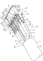
- the perspective view which shows the connector for communication with an electric wire of Embodiment 1 Sectional view showing communication connector with wires
- the perspective view which shows the connector for communication with an electric wire in the state where the shield case was removed Plan view showing cable with wire holding member Side view showing a cable with a wire holding member
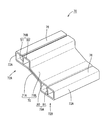
- the perspective view which shows a division member Rear view showing split members The perspective view which shows the communication connector with an electric wire of the state which removed the shield case and the electric wire holding member
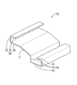
- FIG. The perspective view which shows an electric wire holding member Perspective view showing one split member
- the perspective view which shows the other division member The figure explaining the process of mounting a 2nd electric wire in one division member, and assembling the other division member.
- Embodiment 1 will be described with reference to FIGS. 1 to 8.
- FIG. The communication connector 10 with electric wires is mounted on a vehicle such as an electric vehicle or a hybrid vehicle, for example, between an in-vehicle electrical component (navigation, ETC, monitor, etc.) and an external device (camera etc.) in the vehicle, or between an in-vehicle electrical component.
- Etc. are arranged on a wired communication path. In the following description, it is assumed that the X direction is right, the Y direction is upward, and the Z direction is front.
- the communication connector 10 with electric wire includes a cable 11 and a communication connector 30 provided at a terminal portion of the cable 11.
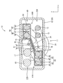
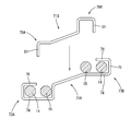
- the cable 11 is capable of high-speed communication of 1 GHz or more, and as shown in FIG. 2, a plurality (10 in this embodiment) of electric wires 12 to 18 and insulation that collectively surrounds the electric wires 12 to 18 And a protective coating 20.
- a shield layer (not shown) formed by braiding fine metal wires collectively surrounds the wires 12 to 18.
- a filling member 21 that fills a gap by filling in an insulating thread or paper tape.
- the plurality of electric wires 12 to 18 includes a first electric wires 12 and 13 for communication (wires capable of communication), second electric wires 14 and 15 capable of performing higher-speed communication than the first electric wires 12 and 13, and two drains. It consists of a line 16, one power line 17 connected to the power source, and one ground line 18 connected to the ground potential.
- the first electric wires 12 and 13 are a pair of electric wires (twisted pair without shield), and are USB 2.0 standard electric wires in this embodiment.
- the second electric wires 14 and 15 are two sets of electric wires different in type from the first electric wires 12 and 13, and are high-speed line pairs (differential pairs with shield and drain lines) having a high maximum data transfer rate.
- USB Universal Serial Bus
- 3.0 standard is used, for example, 5 Gbps transmission is possible.
- the terminal portions of the wires 12 to 18 which are led out from the end portion of the covering 20 and exposed are arranged in the left and right as the two upper and lower wire rows 22A and 22B.
- the adjacent second electric wires 14 and 15 are arranged at the left end (one end portion in the arrangement direction), and in the electric wire row 22B, the adjacent second electric wires 14 and 15 are arranged in the right end portion (in the arrangement direction). It is arranged at the end opposite to the one side).
- the wires 12 to 18 have different thicknesses (outer diameters) depending on the type, and twisted-pair wires (twisted-pair wires) are used, and are twisted back at the portions where the coating 20 is removed and exposed.
- the present invention is not limited to this, and a configuration in which twisted pair wires are not used for the electric wires 12 to 18 may be employed.
- each of the electric wires 12 to 18 is obtained by coating a metal conductor portion 19A with an insulating layer 19B made of an insulating synthetic resin. ), The insulating layer 19B is peeled off, and the conductor portion 19A connected to the terminal 31 is exposed.
- the communication connector 30 includes a plurality (ten in this embodiment) of terminals 31, a housing 35, an electric wire holding member 40, and a shield case 60.
- the terminal 31 has a terminal connection portion 32 on the front side, and a plate-like wire connection portion 33 formed integrally with the terminal connection portion 32 on the rear side of the terminal connection portion 32.
- the terminal connection part 32 is a rectangular tube shape, and is provided with an elastic contact piece that comes into contact with the mating male terminal.
- the conductor portion 19A exposed from the wires 12 to 18 is connected to the wire connecting portion 33 by soldering with solder S, for example.
- connection of the conductor portion 19A to the electric wire connection portion 33 is not limited to soldering, and other known connection methods may be used.
- the conductor portion 19A may be connected to the wire connection portion 33 by ultrasonic welding, laser welding, or the like.
- the housing 35 is made of an insulating synthetic resin, and extends to the rear of the main body 36 in which the terminal connection portions 32 of the terminals 31 are accommodated.
- the thickness dimension in the vertical direction is smaller than that of the main body 36.
- the main body 36 has a rectangular parallelepiped shape, and two cavities 37 in which the terminal connection portions 32 are accommodated are arranged in two rows at the top and bottom and five on the left and right sides with a space therebetween.
- Each cavity 37 has a rectangular cross section corresponding to the outer peripheral shape of the terminal connection portion 32, and extends in the front-rear direction according to the length of the terminal connection portion 32.
- the terminal connection portion 32 is locked inside the cavity 37, so that movement in the front-rear direction is restricted.
- the extending part 38 extends rearward in a plate shape from the middle part in the vertical direction at the rear end of the main body 36, and a groove-like recess is formed on each of the upper surface and the bottom surface of the extending part 38 according to the number of terminals 31. It is formed side by side.
- the wire connecting portion 33 is fitted into the recess.
- the lower terminal 31 is mounted on the housing 35 in an orientation in which the upper terminal 31 is turned upside down.
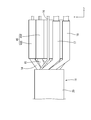
- the electric wire holding member 40 is arranged so as to be connected to the rear of the extending portion 38, and is arranged diagonally with a pair of left and right electric wire accommodating portions 50 surrounding a pair of adjacent second electric wires 14, 15 in a rectangular tube shape. And a connecting portion 51 that connects between the pair of electric wire accommodating portions 50.
- the electric wire holding member 40 includes two (a plurality of) divided members 41A and 41B having the same shape.
- Each of the divided members 41A and 41B is formed by punching and bending a metal plate material such as aluminum, aluminum alloy, copper, or copper alloy. As shown in FIGS. Of the electric wires 14 and 15, the first wall portion 42 that partitions the outer second electric wires 14 and 15 from the outside, the second wall portion 45 that partitions the adjacent second electric wires 14 and 15, and the first wall portion And a connecting plate 48 for connecting the second wall portion 45 and the second wall portion 45.
- the first wall portion 42 includes a bottom plate portion 43 and an L-shaped outer wall portion 44 that stands vertically from the bottom plate portion 43.
- the second wall portion 45 includes an outer wall portion 46 that is bent at an end portion of the connecting plate 48 and extends in an L shape, and a partition wall 47 that is folded back in the vertical direction from the distal end portion of the outer wall portion 46.
- the partition wall 47 is arranged in an intermediate portion between the adjacent second electric wires 14 and 15 to partition the adjacent second electric wires 14 and 15.
- the electric wire accommodating portion 50 is formed by combining the first wall portion 42 of one divided member 41A (41B) and the second wall portion 45 of the other divided member 41B (41A), and a plurality of divided members 41A and 41B are combined. In this state, the entire circumference around the second electric wires 14 and 15 is surrounded by the electric wire accommodating portion 50.
- the connecting portion 51 is configured by overlapping connecting plates 48 and 48.
- the second electric wires 14 and 15 are arranged on one division member 41A (41B), and the second electric wires 14 and 15 can be assembled to the electric wire accommodating portion 50 by assembling the other division member 41B (41A). For example, the second electric wires 14 and 15 may be inserted through the opening of the electric wire housing portion 50 after the divided members 41A and 41B are assembled.
- the shield case 60 is made of a metal such as aluminum or an aluminum alloy. As shown in FIG. 1, the shield case 60 has a rectangular tube-shaped first shield case 61 that covers the main body 36 of the housing 35, and a rear side of the first shield case 61. And a second shield case 63 that covers the plurality of electric wires 12 to 18 and the electric wire holding member 40.
- the second shield case 63 has a box shape with an opening on the front side, and includes a cylindrical shield connection portion 64 that is externally fitted to the cable 11 at the rear end.
- the shield connection portion 64 is connected to the shield layer that is folded back to the outside of the covering 20 at the terminal portion of the cable 11 by, for example, welding or pressure bonding. Since the electric wire holding member 40 is inserted into the second shield case 63 with a slight gap, the divided members 41A and 41B are held in the assembled state in the second shield case 63, and the divided members 41A and 41B The separation of 41B is restricted.
- the communication connector 30 is different from the second electric wires 14 and 15 on one end side in the arrangement direction in the electric wire row 22A and the electric wire row 22A by the conductive electric wire holding member 40.
- the relative position of the second electric wires 14 and 15 on the opposite end side in the arrangement direction of the electric wire row 22B is maintained, and the second electric wires 14 and 15 are surrounded.
- the electric wire holding member 40 is comprised so that the surroundings of the 2nd electric wires 14 and 15 may be enclosed in the state in which several division member 41A, 41B was combined, the 2nd electric wires 14, The work of assembling 15 can be simplified.
- a plurality of terminals 31 can be arranged in a plurality of rows by arranging the plurality of electric wire rows 22A and 22B in parallel. Thus, the arrangement space is hardly restricted.
- column 22A, 22B has the some 2nd electric wires 14 and 15 adjacent, and each division member 41A, 41B is an outer 2nd electric wire among the some adjacent 2nd electric wires 14,15.
- a first wall portion 42 that partitions 14 and 15 from the outside and a second wall portion 45 that partitions a plurality of adjacent second electric wires 14 and 15 are provided. In this way, it is possible to suppress changes in the impedance of the electric wires 12 to 18 with a simple configuration.
- the embodiment will be described with reference to FIGS.
- the communication connector according to the second embodiment is obtained by changing the shapes of the split members 71A and 71B in the electric wire holding member 70. Since other configurations are the same as those of the first embodiment, the same configurations as those of the first embodiment are denoted by the same reference numerals and description thereof is omitted.
- the electric wire holding member 70 is formed by punching and bending a metal plate material such as aluminum, aluminum alloy, copper, copper alloy, and individually surrounds the pair of second electric wires 14, 15 as shown in FIG. A pair of left and right electric wire accommodating portions 72A and 72B, and a connecting portion 83 that couples the pair of electric wire accommodating portions 50 arranged diagonally.
- the electric wire holding member 70 includes a pair of divided members 71A and 71B, and one divided member 71A is arranged outside the second electric wires 14 and 15 as shown in FIG.
- a pair of left and right first wall portions 73A and 73B and a connecting plate 77 for connecting the first wall portions 73A and 73B arranged diagonally are provided.
- the first wall portions 73 ⁇ / b> A and 73 ⁇ / b> B include a placement portion 74 on which the second electric wires 14 and 15 are placed, a side wall portion 75 that stands vertically from the end portion of the placement portion 74, and an end portion of the side wall portion 75.
- a lid portion 76 that is vertically folded toward the placement portion 74 is provided.
- the other split member 71B is shaped to be fitted inside the split member 71A, and connects the pair of second wall portions 79A and 79B that partition the second electric wires 14 and 15 and the second wall portions 79A and 79B. And a connecting plate 82.
- the second wall portions 79 ⁇ / b> A and 79 ⁇ / b> B include a lid portion 80 that covers the second electric wire 15 and a partition portion 81 that partitions the second electric wires 14 and 15.
- the wire accommodating portions 72A and 72B are formed by combining the first wall portions 73A and 73B and the second wall portions 79A and 79B, and the connecting portion 83 is configured by overlapping the connecting plates 77 and 82.
- the split member 71B is placed inside the split member 71A.
- the electric wire holding member 70 is formed by being mounted, and the second electric wires 14 and 15 are partitioned by the partitioning portion 81 (FIG. 9).
- each of the electric wire rows 22A and 22B has a plurality of adjacent second electric wires 14 and 15, and one (at least one) dividing member 71A is provided in each of the electric wire rows 22A and 22B.
- the outer second electric wires 14 are separated from the outside by a plurality of first wall portions 73A and 73B, and the other (at least one other) dividing member 71B is The plurality of second wall portions 79A and 79B partitioning the plurality of adjacent second electric wires 14 and 15 in the electric wire rows 22A and 22B. In this way, it is possible to facilitate the assembling work when the electric wires 12 to 18 are arranged and assembled between the plurality of divided members 71A and 71B.
- the number of the electric wires 12 to 18 is not limited to the number described above, and may be different.
- the 2nd electric wires 14 and 15 were distribute
- the 2nd electric wires 14 and 15 may be arrange
- the split members 41A and 41B (71A and 71B) are provided with a locking portion that is locked to the other when assembled, so that the separation between the split members 41A and 41B (71A and 71B) is regulated. May be.
Abstract
通信用コネクタ(30)は、第1電線(12,13)と第1電線(12,13)よりも高速通信が可能な第2電線(14,15)と含んだ電線列(22A,22B)を複数形成する複数の電線(12~18)と、複数の電線(12~18)に接続される複数の端子(31)と、複数の端子(31)を収容するハウジング(35)と、電線列(22A)における並び方向の一方の端部側の第2電線(14,15)と電線列(22A)とは異なる電線列(22B)の並び方向における前記一方とは反対側の端部側の第2電線(14,15)との相対的位置を保持する導電性の電線保持部材(40)と、を備え、電線保持部材(40)は、複数の分割部材(41A,41B)からなり、複数の分割部材(41A,41B)が組み合わされた状態で第2電線(14,15)の周りを包囲するように構成されている。
Description
本明細書では、通信用コネクタに関する技術を開示する。
従来、通信用コネクタが知られている。特許文献1には、4つのUSBプラグコネクタを受けることができる電気コネクタが記載されている。この電気コネクタは、ハウジングと、L字に屈曲された金属からなる電気接点と、外部シールドと、内部シールドとを備えている。電気接点は、各USBプラグコネクタごとに左右に複数並んで固定されている。
ところで、導電体として金属の棒ではなく、複数の電線が一括して被覆されたケーブルを用いた場合、ケーブルの端末部における被覆を除去した部分は、複数の電線が露出することになる。この電線が露出した部分は、複数の電線間の間隔が変わりやすいため、電線のインピーダンスの変化点が生じて信号が反射し、通信品質が低下することが懸念される。
本明細書で開示された技術は上記のような事情に基づいて完成されたものであって、通信品質の低下を抑制することを目的とする。
本明細書で開示された通信用コネクタは、第1電線と前記第1電線よりも高速通信が可能な第2電線とを含んだ電線列を複数形成する複数の電線と、前記複数の電線に接続される複数の端子と、前記複数の端子を収容するハウジングと、前記電線列における並び方向の一方の端部側の前記第2電線と前記電線列とは異なる電線列の並び方向における前記一方とは反対側の端部側の前記第2電線との相対的位置を保持する導電性の電線保持部材と、を備え、前記電線保持部材は、複数の分割部材からなり、前記複数の分割部材が組み合わされた状態で前記第2電線の周りを包囲するように構成されている。
本構成によれば、導電性の電線保持部材により、異なる電線列において対角となる位置に配された第2電線の相対的位置が保持されつつ、第2電線の周りが包囲されるため、電線間のインピーダンスが変化しやすい位置関係にある第2電線について、電線間の電位が安定し、第2電線のインピーダンスの変化を抑制することができる。これにより、インピーダンスの変化点における信号の反射を抑制できるため、通信品質の低下を抑制することができる。
また、電線保持部材は、複数の分割部材が組み合わされた状態で前記第2電線の周りを包囲するように構成されているため、電線保持部材に電線を挿通する作業を簡素化することができる。
また、電線保持部材は、複数の分割部材が組み合わされた状態で前記第2電線の周りを包囲するように構成されているため、電線保持部材に電線を挿通する作業を簡素化することができる。
また、例えばハウジングに複数の端子を1列に並べる構成とすると、端子の並び方向について通信用コネクタが長くなりやすいため、配置スペースに制約が生じやすいという問題がある。一方、本構成によれば、複数の電線が複数の電線列を構成しているため、通信用コネクタが全体として纏まった形状となって、配置スペースの制約が生じにくくなる。
本明細書で開示された技術の実施態様としては以下の態様が好ましい。
各前記電線列は、隣り合う複数の前記第2電線を有し、各前記分割部材は、前記隣り合う複数の第2電線のうち、外側の前記第2電線を外部と仕切る第1壁部と、前記隣り合う複数の第2電線間を仕切る第2壁部とを備える。
このようにすれば、簡素な構成で、電線のインピーダンスの変化を抑制することができる。
各前記電線列は、隣り合う複数の前記第2電線を有し、各前記分割部材は、前記隣り合う複数の第2電線のうち、外側の前記第2電線を外部と仕切る第1壁部と、前記隣り合う複数の第2電線間を仕切る第2壁部とを備える。
このようにすれば、簡素な構成で、電線のインピーダンスの変化を抑制することができる。
各前記電線列は、隣り合う前記複数の第2電線を有し、前記複数の分割部材のうち、少なくとも一つの前記分割部材は、各前記電線列における前記隣り合う複数の第2電線のうち、外側の前記第2電線を外部と仕切る複数の第1壁部を有し、他の少なくとも一つの前記分割部材は、各前記電線列における前記隣り合う複数の第2電線間を仕切る複数の第2壁部を有する。
このようにすれば、複数の分割部材間に電線を配して組み付ける際の組付作業を容易にすることができる。
このようにすれば、複数の分割部材間に電線を配して組み付ける際の組付作業を容易にすることができる。
前記通信用コネクタと、前記端子に接続される電線と、を備える電線付き通信用コネクタとする。
本明細書で開示された技術によれば、通信品質の低下を抑制することができる。
<実施形態1>
実施形態1について、図1~図8を参照して説明する。
電線付き通信用コネクタ10は、例えば電気自動車やハイブリット自動車等の車両に搭載され、車両内における車載電装品(ナビ、ETC、モニタ等)と外部機器(カメラ等)との間や車載電装品間等の有線の通信経路に配される。以下では、X方向を右方、Y方向を上方、Z方向を前方として説明する。
実施形態1について、図1~図8を参照して説明する。
電線付き通信用コネクタ10は、例えば電気自動車やハイブリット自動車等の車両に搭載され、車両内における車載電装品(ナビ、ETC、モニタ等)と外部機器(カメラ等)との間や車載電装品間等の有線の通信経路に配される。以下では、X方向を右方、Y方向を上方、Z方向を前方として説明する。
(電線付き通信用コネクタ10)
電線付き通信用コネクタ10は、図1に示すように、ケーブル11と、ケーブル11の端末部に備えられた通信用コネクタ30とを備える。
(ケーブル11)
ケーブル11は、1GHz以上の高速の通信が可能であって、図2に示すように、複数(本実施形態では10本)の電線12~18と、電線12~18を一括して包囲する絶縁性の被覆20とを備えている。被覆20の内側には、金属細線を編み込んで構成されたシールド層(図示しない)が電線12~18を一括して包囲している。このシールド層の内側には、絶縁性の糸や紙テープ等を詰め込んで隙間を埋める充填部材21が充填されている。
電線付き通信用コネクタ10は、図1に示すように、ケーブル11と、ケーブル11の端末部に備えられた通信用コネクタ30とを備える。
(ケーブル11)
ケーブル11は、1GHz以上の高速の通信が可能であって、図2に示すように、複数(本実施形態では10本)の電線12~18と、電線12~18を一括して包囲する絶縁性の被覆20とを備えている。被覆20の内側には、金属細線を編み込んで構成されたシールド層(図示しない)が電線12~18を一括して包囲している。このシールド層の内側には、絶縁性の糸や紙テープ等を詰め込んで隙間を埋める充填部材21が充填されている。
複数の電線12~18は、通信用の第1電線12,13(通信可能な電線)と、第1電線12,13よりも高速通信が可能な第2電線14,15と、2本のドレイン線16と、電源に接続される1本の電源線17と、グランド電位に接続される1本のグランド線18とからなる。第1電線12,13は、1組の対(シールドなしのツイスト・ペア)の電線であり、本実施形態ではUSB2.0規格の電線である。第2電線14,15は、第1電線12,13とは種類が異なる2組の電線であって、データの最大転送速度が速い高速線対(シールドとドレイン線付の差動ペア)であり、本実施形態ではUSB(Universal Serial Bus)3.0規格で、例えば5Gbpsの伝送が可能とされている。
被覆20の端部から導出されて露出した電線12~18の端末部は、上下2段の電線列22A,22Bとして左右に5本並べられている。電線列22Aは、隣り合う第2電線14,15が左端部(並び方向の一方側の端部)に配され、電線列22Bは、隣り合う第2電線14,15が右端部(並び方向の一方側とは反対側の端部)に配されている。
電線12~18は、種類に応じて太さ(外径)が異なっており、ツイストペア線(撚り対線)が用いられ、被覆20が除去されて露出する部分において撚り戻されている。なお、これに限られず、電線12~18にツイストペア線を用いない構成としてもよい。また、各電線12~18は、図8に示すように、金属の導体部19Aを、絶縁性の合成樹脂からなる絶縁層19Bで被覆したものであり、電線12~18の端末部(先端部)は、絶縁層19Bが剥ぎ取られ、端子31と接続される導体部19Aが露出している。
(通信用コネクタ30)
通信用コネクタ30は、図2,図3に示すように、複数(本実施形態では10個)の端子31と、ハウジング35と、電線保持部材40と、シールドケース60とを備えている。
(端子31)
端子31は、前方側が端子接続部32とされ、端子接続部32の後方側に板状の電線接続部33が端子接続部32と一体に形成されている。端子接続部32は、角筒状であって、相手側のオス端子に接触する弾性接触片が設けられている。電線接続部33には、電線12~18から露出した導体部19Aが例えば半田Sによる半田付けで接続されている。なお、導体部19Aの電線接続部33への接続は、半田付けに限られず、他の公知の接続方法を用いてもよい。例えば、超音波溶接やレーザ溶接等により導体部19Aを電線接続部33に接続してもよい。
(ハウジング35)
ハウジング35は、絶縁性の合成樹脂製であって、各端子31の端子接続部32が収容される本体36と、本体36の後方に延出され、本体36よりも上下方向の厚み寸法が小さい延出部38とを備える。本体36は、直方体状であって、端子接続部32が収容されるキャビティ37が上下2段、左右に5個、間隔を空けて並んで配置されている。各キャビティ37は、端子接続部32の外周形状に応じた矩形状の断面を有し、端子接続部32の長さに応じて前後方向に延びている。端子接続部32は、キャビティ37の内部で係止されることにより、前後方向の移動が規制されている。延出部38は、本体36の後端における上下方向の中間部から板状に後方に延びており、延出部38の上面と底面のそれぞれに端子31の数に応じて溝状の凹部が左右に並んで形成されている。この凹部に電線接続部33が嵌め入れられる。なお、下段側の端子31は、上段側の端子31を裏返した向きでハウジング35に装着されている。
ハウジング35は、絶縁性の合成樹脂製であって、各端子31の端子接続部32が収容される本体36と、本体36の後方に延出され、本体36よりも上下方向の厚み寸法が小さい延出部38とを備える。本体36は、直方体状であって、端子接続部32が収容されるキャビティ37が上下2段、左右に5個、間隔を空けて並んで配置されている。各キャビティ37は、端子接続部32の外周形状に応じた矩形状の断面を有し、端子接続部32の長さに応じて前後方向に延びている。端子接続部32は、キャビティ37の内部で係止されることにより、前後方向の移動が規制されている。延出部38は、本体36の後端における上下方向の中間部から板状に後方に延びており、延出部38の上面と底面のそれぞれに端子31の数に応じて溝状の凹部が左右に並んで形成されている。この凹部に電線接続部33が嵌め入れられる。なお、下段側の端子31は、上段側の端子31を裏返した向きでハウジング35に装着されている。
(電線保持部材40)
電線保持部材40は、延出部38の後方に連なるように配され、隣り合う一対の第2電線14,15を角筒状に包囲する左右一対の電線収容部50と、対角に配置された一対の電線収容部50間を連結する連結部51とを備えている。この電線保持部材40は、同一形状の2個(複数)の分割部材41A,41Bからなる。
電線保持部材40は、延出部38の後方に連なるように配され、隣り合う一対の第2電線14,15を角筒状に包囲する左右一対の電線収容部50と、対角に配置された一対の電線収容部50間を連結する連結部51とを備えている。この電線保持部材40は、同一形状の2個(複数)の分割部材41A,41Bからなる。
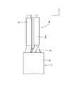
分割部材41A,41Bは、共に、アルミニウム、アルミニウム合金、銅、銅合金等の金属板材に打ち抜き加工及び曲げ加工を施して形成され、図6,図7に示すように、隣り合う複数の第2電線14,15のうち、外側の第2電線14,15を外部と仕切る第1壁部42と、隣り合う複数の第2電線14,15間を仕切る第2壁部45と、第1壁部42と第2壁部45とを連結する連結板48とを備えている。
第1壁部42は、底板部43と、底板部43から垂直方向に起立するL字状の外壁部44とを備えている。第2壁部45は、連結板48の端部で屈曲されてL字状に延びる外壁部46と、外壁部46の先端部から垂直方向に折り返す仕切り壁47とを有する。仕切り壁47は、隣り合う第2電線14,15の中間部に配されて、隣り合う第2電線14,15を仕切る。
電線収容部50は、一方の分割部材41A(41B)の第1壁部42と他方の分割部材41B(41A)の第2壁部45を組み合わせて形成され、複数の分割部材41A,41Bが組み合わされた状態で第2電線14,15の周りの全周が電線収容部50によって包囲される。連結部51は、連結板48,48を重ねて構成される。一方の分割部材41A(41B)の上に第2電線14,15配して、他方の分割部材41B(41A)を組み付けることで電線収容部50に第2電線14,15を組み付けることができる。なお、これに限られず、例えば、分割部材41A,41Bの組み付け後に、電線収容部50の開口から第2電線14,15を挿通するようにしてもよい。
(シールドケース60)
シールドケース60は、アルミニウムやアルミニウム合金等の金属製であって、図1に示すように、ハウジング35の本体36を覆う角筒状の第1シールドケース61と、第1シールドケース61の後方に配されて複数の電線12~18及び電線保持部材40を覆う第2シールドケース63とを備えている。第2シールドケース63は、前方側が開口した箱形であって、後端部にケーブル11に外嵌する円筒形状のシールド接続部64を備えている。シールド接続部64は、例えばケーブル11の端末部において被覆20の外側に折り返したシールド層に、例えば溶接や圧着等により接続される。第2シールドケース63内に電線保持部材40がわずかな隙間を有して挿通されるため、分割部材41A,41Bは、第2シールドケース63内で組み付けられた状態に保持され、分割部材41A,41Bの離間が規制されている。
シールドケース60は、アルミニウムやアルミニウム合金等の金属製であって、図1に示すように、ハウジング35の本体36を覆う角筒状の第1シールドケース61と、第1シールドケース61の後方に配されて複数の電線12~18及び電線保持部材40を覆う第2シールドケース63とを備えている。第2シールドケース63は、前方側が開口した箱形であって、後端部にケーブル11に外嵌する円筒形状のシールド接続部64を備えている。シールド接続部64は、例えばケーブル11の端末部において被覆20の外側に折り返したシールド層に、例えば溶接や圧着等により接続される。第2シールドケース63内に電線保持部材40がわずかな隙間を有して挿通されるため、分割部材41A,41Bは、第2シールドケース63内で組み付けられた状態に保持され、分割部材41A,41Bの離間が規制されている。
本実施形態によれば、以下の作用、効果を奏する。
本実施形態によれば、通信用コネクタ30は、導電性の電線保持部材40により、電線列22Aにおける並び方向の一方の端部側の第2電線14,15、及び、電線列22Aとは異なる電線列22Bの並び方向における反対側の端部側の第2電線14,15の相対的位置を保持し、かつ、第2電線14,15の周りを包囲する。これにより、異なる電線列22A,22Bにおいて対角となる位置に配された第2電線14,15の相対的位置を保持しつつ、第2電線14,15の周りをシールドすることができるため、電線12~18間のインピーダンスが変化しやすい部分について、電線12~18間の電位が安定し、電線12~18のインピーダンスの変化を抑制することができる。よって、インピーダンスの変化点における信号の反射を抑制できるため、通信品質の低下を抑制することができる。特に、高速信号を伝送する第2電線14,15は、信号が反射や放射されることによって信号が劣化しやすいが、本実施形態によれば、このような場合に信号の反射や放射による劣化を抑制することができる。
また、電線保持部材40は、複数の分割部材41A,41Bが組み合わされた状態で第2電線14,15の周りを包囲するように構成されているため、電線保持部材40に第2電線14,15を組み付ける作業を簡素化することができる。
また、例えばハウジング35に複数の端子31を一列に並べる構成とすると、端子31の並び方向について通信用コネクタ30が長くなりやすいため、配置スペースに制約が生じやすいという問題がある。一方、本実施形態によれば、複数の電線列22A,22Bが並列に配されることで、複数の端子31を複数列に並べることができるため、通信用コネクタ30が全体として纏まった形状となって、配置スペースの制約が生じにくくなる。
また、各電線列22A,22Bは、隣り合う複数の第2電線14,15を有し、各分割部材41A,41Bは、隣り合う複数の第2電線14,15のうち、外側の第2電線14,15を外部と仕切る第1壁部42と、隣り合う複数の第2電線14,15間を仕切る第2壁部45とを備える。
このようにすれば、簡素な構成で、電線12~18のインピーダンスの変化を抑制することができる。
このようにすれば、簡素な構成で、電線12~18のインピーダンスの変化を抑制することができる。
<実施形態2>
実施形態を図9~図13を参照して説明する。
実施形態2の通信用コネクタは、電線保持部材70における分割部材71A,71Bの形状を変えたものである。他の構成は、実施形態1と同一であるため、以下では実施形態1と同一の構成は同一の符号を付して説明を省略する。
実施形態を図9~図13を参照して説明する。
実施形態2の通信用コネクタは、電線保持部材70における分割部材71A,71Bの形状を変えたものである。他の構成は、実施形態1と同一であるため、以下では実施形態1と同一の構成は同一の符号を付して説明を省略する。
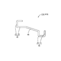
電線保持部材70は、アルミニウム、アルミニウム合金、銅、銅合金等の金属板材に打ち抜き加工及び曲げ加工を施して形成され、図9に示すように、一対の第2電線14,15を個別に包囲する左右一対の電線収容部72A,72Bと、対角に配置された一対の電線収容部50間を連結する連結部83とを備えている。この電線保持部材70は、図10に示すように、一対の分割部材71A,71Bからなり、一方の分割部材71Aは、図11に示すように、第2電線14,15の外側に配される左右一対の第1壁部73A,73Bと、対角に配された第1壁部73A,73B間を連結する連結板77とを備えている。第1壁部73A,73Bは、第2電線14,15が載置される載置部74と、載置部74の端部から垂直に起立する側壁部75と、側壁部75の端部から垂直に載置部74側に折り返す蓋部76とを備えている。
他方の分割部材71Bは、分割部材71Aの内側に嵌め入れられる形状であり、第2電線14,15間を仕切る一対の第2壁部79A,79Bと、第2壁部79A,79B間を連結する連結板82とを備えている。第2壁部79A,79Bは、第2電線15を覆う蓋部80と、第2電線14,15間を仕切る仕切部81とを備えている。電線収容部72A,72Bは、第1壁部73A,73Bと第2壁部79A,79Bを組み合わせて形成され、連結部83は、連結板77,82を重ねて構成される。
図13に示すように、分割部材71Aの左右両側の載置部74に、第2電線14,15を載置し、分割部材71Bを上方から被せると、分割部材71Aの内側に分割部材71Bが装着されて電線保持部材70が形成され、第2電線14,15間が仕切部81で仕切られた状態となる(図9)。
実施形態2の通信用コネクタは、各電線列22A,22Bは、隣り合う複数の第2電線14,15を有し、一方(少なくとも一つ)の分割部材71Aは、各電線列22A,22Bにおける隣り合う複数の第2電線14,15のうち、外側の第2電線14,を外部と仕切る複数の第1壁部73A,73Bを有し、他方(他の少なくとも一つ)の分割部材71Bは、各電線列22A,22Bにおける隣り合う複数の第2電線14,15間を仕切る複数の第2壁部79A,79Bを有する。このようにすれば、複数の分割部材71A,71B間に電線12~18を配して組み付ける際の組付作業を容易にすることができる。
<他の実施形態>
本発明は上記記述及び図面によって説明した実施形態に限定されるものではなく、例えば次のような実施形態も本発明の技術的範囲に含まれる。
(1)電線保持部材を構成する分割部材41A,41B,71A,71Bの数は、2個としたが、これに限られず、3個以上としてもよい。また、分割部材の形状は、上記実施形態の形状に限られず、種々の形状に変更することができる。
本発明は上記記述及び図面によって説明した実施形態に限定されるものではなく、例えば次のような実施形態も本発明の技術的範囲に含まれる。
(1)電線保持部材を構成する分割部材41A,41B,71A,71Bの数は、2個としたが、これに限られず、3個以上としてもよい。また、分割部材の形状は、上記実施形態の形状に限られず、種々の形状に変更することができる。
(2)電線12~18の本数は、上記した本数に限られず、異なる本数としてもよい。
(3)第2電線14,15は、電線列22A,22Bの並び方向の端部に配されたが、電線列の第2電線14,15が概ね対角となる位置関係であれば、電線列の並び方向の端部でなくてもよい。例えば、並び方向の中間部よりも端部側に第2電線14,15が配置されていてもよい。この場合、第2電線14,15よりも並び方向の端部側(外側)に他の電線を有してもよい。
(3)第2電線14,15は、電線列22A,22Bの並び方向の端部に配されたが、電線列の第2電線14,15が概ね対角となる位置関係であれば、電線列の並び方向の端部でなくてもよい。例えば、並び方向の中間部よりも端部側に第2電線14,15が配置されていてもよい。この場合、第2電線14,15よりも並び方向の端部側(外側)に他の電線を有してもよい。
(4)分割部材41A,41B(71A,71B)に、組み付けた際に他方に係止する係止部を設けて、分割部材41A,41B(71A,71B)間の離間が規制されるようにしてもよい。
10: 電線付き通信用コネクタ
11: ケーブル
12~18: 電線
12,13: 第1電線
14,15: 第2電線
15: 第2電線
22A,22B: 電線列
30: 通信用コネクタ
31: 端子
35: ハウジング
40,70: 電線保持部材
41A,41B,71A,71B: 分割部材
42,73A,73B: 第1壁部
45,79A,79B: 第2壁部
60: シールドケース
11: ケーブル
12~18: 電線
12,13: 第1電線
14,15: 第2電線
15: 第2電線
22A,22B: 電線列
30: 通信用コネクタ
31: 端子
35: ハウジング
40,70: 電線保持部材
41A,41B,71A,71B: 分割部材
42,73A,73B: 第1壁部
45,79A,79B: 第2壁部
60: シールドケース
Claims (4)
- 第1電線と前記第1電線よりも高速通信が可能な第2電線とを含んだ電線列を複数形成する複数の電線と、
前記複数の電線に接続される複数の端子と、
前記複数の端子を収容するハウジングと、
前記電線列における並び方向の一方の端部側の前記第2電線と前記電線列とは異なる電線列の並び方向における前記一方とは反対側の端部側の前記第2電線との相対的位置を保持する導電性の電線保持部材と、を備え、
前記電線保持部材は、複数の分割部材からなり、前記複数の分割部材が組み合わされた状態で前記第2電線の周りを包囲するように構成されている、通信用コネクタ。 - 各前記電線列は、隣り合う複数の前記第2電線を有し、各前記分割部材は、前記隣り合う複数の第2電線のうち、外側の前記第2電線を外部と仕切る第1壁部と、前記隣り合う複数の第2電線間を仕切る第2壁部とを備える請求項1に記載の通信用コネクタ。
- 各前記電線列は、隣り合う前記複数の第2電線を有し、
前記複数の分割部材のうち、少なくとも一つの前記分割部材は、各前記電線列における前記隣り合う複数の第2電線のうち、外側の前記第2電線を外部と仕切る複数の第1壁部を有し、他の少なくとも一つの前記分割部材は、各前記電線列における前記隣り合う複数の第2電線間を仕切る複数の第2壁部を有する請求項1に記載の通信用コネクタ。 - 請求項1から請求項3のいずれか一項に記載の通信用コネクタと、前記端子に接続される電線と、を備える電線付き通信用コネクタ。
Priority Applications (2)
| Application Number | Priority Date | Filing Date | Title |
|---|---|---|---|
| CN201680050761.5A CN107925200B (zh) | 2015-09-09 | 2016-09-05 | 通信用连接器以及带电线的通信用连接器 |
| US15/756,159 US10367306B2 (en) | 2015-09-09 | 2016-09-05 | Communication connector and communication connector with wires |
Applications Claiming Priority (2)
| Application Number | Priority Date | Filing Date | Title |
|---|---|---|---|
| JP2015177275A JP6443274B2 (ja) | 2015-09-09 | 2015-09-09 | 通信用コネクタ及び電線付き通信用コネクタ |
| JP2015-177275 | 2015-09-09 |
Publications (1)
| Publication Number | Publication Date |
|---|---|
| WO2017043435A1 true WO2017043435A1 (ja) | 2017-03-16 |
Family
ID=58239595
Family Applications (1)
| Application Number | Title | Priority Date | Filing Date |
|---|---|---|---|
| PCT/JP2016/075957 WO2017043435A1 (ja) | 2015-09-09 | 2016-09-05 | 通信用コネクタ及び電線付き通信用コネクタ |
Country Status (4)
| Country | Link |
|---|---|
| US (1) | US10367306B2 (ja) |
| JP (1) | JP6443274B2 (ja) |
| CN (1) | CN107925200B (ja) |
| WO (1) | WO2017043435A1 (ja) |
Families Citing this family (4)
| Publication number | Priority date | Publication date | Assignee | Title |
|---|---|---|---|---|
| JP6866887B2 (ja) * | 2018-12-28 | 2021-04-28 | 株式会社オートネットワーク技術研究所 | 端子付き電線、端子モジュールおよびコネクタ |
| JP7140021B2 (ja) * | 2019-03-22 | 2022-09-21 | 住友電装株式会社 | 端子付き電線 |
| JP2021015739A (ja) * | 2019-07-12 | 2021-02-12 | 住友電装株式会社 | コネクタモジュール、コネクタ付通信ケーブル、及びコネクタアセンブリ |
| US11696426B2 (en) * | 2020-02-26 | 2023-07-04 | Marvell Asia Pte Ltd | Automotive network communication devices and cabling with electromagnetic shielding |
Citations (5)
| Publication number | Priority date | Publication date | Assignee | Title |
|---|---|---|---|---|
| WO1999017406A1 (en) * | 1997-09-26 | 1999-04-08 | The Whitaker Corporation | Modular plug having load bar for crosstalk reduction |
| JP2001515651A (ja) * | 1998-01-15 | 2001-09-18 | ザ シーモン カンパニー | 性能が向上した電気通信コネクタ |
| JP2006114337A (ja) * | 2004-10-14 | 2006-04-27 | Molex Inc | ケーブル用コネクタ及びコネクタ組立体 |
| JP2010049961A (ja) * | 2008-08-22 | 2010-03-04 | Japan Aviation Electronics Industry Ltd | コネクタ |
| JP2012018898A (ja) * | 2010-06-08 | 2012-01-26 | Hirose Electric Co Ltd | 電気コネクタ、およびツイストペアケーブルと電気コネクタとの接続方法 |
Family Cites Families (10)
| Publication number | Priority date | Publication date | Assignee | Title |
|---|---|---|---|---|
| US5785555A (en) * | 1996-03-01 | 1998-07-28 | Molex Incorporated | System for terminating the shield of a high speed cable |
| US5718607A (en) * | 1996-03-01 | 1998-02-17 | Molex Incorporated | System for terminating the shield of a high speed cable |
| US6328601B1 (en) | 1998-01-15 | 2001-12-11 | The Siemon Company | Enhanced performance telecommunications connector |
| US6380485B1 (en) * | 2000-08-08 | 2002-04-30 | International Business Machines Corporation | Enhanced wire termination for twinax wires |
| EP1436863A1 (en) * | 2001-10-17 | 2004-07-14 | Molex Incorporated | Connector with improved grounding means |
| JP4082602B2 (ja) * | 2003-10-24 | 2008-04-30 | 矢崎総業株式会社 | シールド電線の接続構造 |
| US7081017B2 (en) | 2004-07-19 | 2006-07-25 | Fci Americas Technology, Inc. | USB electrical connector |
| US7364470B2 (en) * | 2006-07-05 | 2008-04-29 | Commscope, Inc. Of North Carolina | Communications connectors with signal current splitting |
| JP5008492B2 (ja) * | 2007-08-01 | 2012-08-22 | 株式会社オートネットワーク技術研究所 | シールドコネクタ |
| JP6455361B2 (ja) * | 2015-08-20 | 2019-01-23 | 株式会社オートネットワーク技術研究所 | 通信用コネクタ及び電線付き通信用コネクタ |
-
2015
- 2015-09-09 JP JP2015177275A patent/JP6443274B2/ja active Active
-
2016
- 2016-09-05 CN CN201680050761.5A patent/CN107925200B/zh active Active
- 2016-09-05 US US15/756,159 patent/US10367306B2/en active Active
- 2016-09-05 WO PCT/JP2016/075957 patent/WO2017043435A1/ja active Application Filing
Patent Citations (5)
| Publication number | Priority date | Publication date | Assignee | Title |
|---|---|---|---|---|
| WO1999017406A1 (en) * | 1997-09-26 | 1999-04-08 | The Whitaker Corporation | Modular plug having load bar for crosstalk reduction |
| JP2001515651A (ja) * | 1998-01-15 | 2001-09-18 | ザ シーモン カンパニー | 性能が向上した電気通信コネクタ |
| JP2006114337A (ja) * | 2004-10-14 | 2006-04-27 | Molex Inc | ケーブル用コネクタ及びコネクタ組立体 |
| JP2010049961A (ja) * | 2008-08-22 | 2010-03-04 | Japan Aviation Electronics Industry Ltd | コネクタ |
| JP2012018898A (ja) * | 2010-06-08 | 2012-01-26 | Hirose Electric Co Ltd | 電気コネクタ、およびツイストペアケーブルと電気コネクタとの接続方法 |
Also Published As
| Publication number | Publication date |
|---|---|
| JP2017054667A (ja) | 2017-03-16 |
| JP6443274B2 (ja) | 2018-12-26 |
| US10367306B2 (en) | 2019-07-30 |
| CN107925200A (zh) | 2018-04-17 |
| US20180248319A1 (en) | 2018-08-30 |
| CN107925200B (zh) | 2020-04-21 |
Similar Documents
| Publication | Publication Date | Title |
|---|---|---|
| US10148039B2 (en) | Communication connector | |
| JP6330587B2 (ja) | 通信用コネクタ | |
| WO2017043435A1 (ja) | 通信用コネクタ及び電線付き通信用コネクタ | |
| JP6459747B2 (ja) | 通信用コネクタ | |
| WO2016035841A1 (ja) | 通信用コネクタ | |
| US10374367B2 (en) | Communication connector and housing with a metal partition wall between wires | |
| US10008809B2 (en) | Shield connector | |
| JP6332087B2 (ja) | 通信用コネクタ | |
| JP6332222B2 (ja) | コネクタ付きケーブル | |
| JP6097165B2 (ja) | コネクタ | |
| US9461429B2 (en) | Electrical connector assembly having extra signal contact | |
| CN107431326B (zh) | 通信用连接器 | |
| WO2016121502A1 (ja) | 通信用コネクタ | |
| JP6583481B2 (ja) | 通信用コネクタ | |
| CN104103966A (zh) | 线缆连接器组件 | |
| US20200313361A1 (en) | Connector | |
| JP2020181706A (ja) | 電気コネクタ |
Legal Events
| Date | Code | Title | Description |
|---|---|---|---|
| 121 | Ep: the epo has been informed by wipo that ep was designated in this application |
Ref document number: 16844296 Country of ref document: EP Kind code of ref document: A1 |
|
| WWE | Wipo information: entry into national phase |
Ref document number: 15756159 Country of ref document: US |
|
| NENP | Non-entry into the national phase |
Ref country code: DE |
|
| 122 | Ep: pct application non-entry in european phase |
Ref document number: 16844296 Country of ref document: EP Kind code of ref document: A1 |