WO2017043320A1 - オゾン供給装置 - Google Patents
オゾン供給装置 Download PDFInfo
- Publication number
- WO2017043320A1 WO2017043320A1 PCT/JP2016/074738 JP2016074738W WO2017043320A1 WO 2017043320 A1 WO2017043320 A1 WO 2017043320A1 JP 2016074738 W JP2016074738 W JP 2016074738W WO 2017043320 A1 WO2017043320 A1 WO 2017043320A1
- Authority
- WO
- WIPO (PCT)
- Prior art keywords
- housing
- ozonizer
- ozone
- air
- traveling wind
- Prior art date
- Legal status (The legal status is an assumption and is not a legal conclusion. Google has not performed a legal analysis and makes no representation as to the accuracy of the status listed.)
- Ceased
Links
Images








Classifications
-
- C—CHEMISTRY; METALLURGY
- C01—INORGANIC CHEMISTRY
- C01B—NON-METALLIC ELEMENTS; COMPOUNDS THEREOF; METALLOIDS OR COMPOUNDS THEREOF NOT COVERED BY SUBCLASS C01C
- C01B13/00—Oxygen; Ozone; Oxides or hydroxides in general
- C01B13/10—Preparation of ozone
- C01B13/11—Preparation of ozone by electric discharge
-
- C—CHEMISTRY; METALLURGY
- C01—INORGANIC CHEMISTRY
- C01B—NON-METALLIC ELEMENTS; COMPOUNDS THEREOF; METALLOIDS OR COMPOUNDS THEREOF NOT COVERED BY SUBCLASS C01C
- C01B3/00—Hydrogen; Gaseous mixtures containing hydrogen; Separation of hydrogen from mixtures containing it; Purification of hydrogen; Reversible storage of hydrogen
- C01B3/02—Production of hydrogen; Production of gaseous mixtures containing hydrogen
- C01B3/32—Production of hydrogen; Production of gaseous mixtures containing hydrogen by reaction of gaseous or liquid organic compounds with gasifying agents, e.g. water, carbon dioxide or air
- C01B3/34—Production of hydrogen; Production of gaseous mixtures containing hydrogen by reaction of gaseous or liquid organic compounds with gasifying agents, e.g. water, carbon dioxide or air by reaction of hydrocarbons with gasifying agents
- C01B3/36—Production of hydrogen; Production of gaseous mixtures containing hydrogen by reaction of gaseous or liquid organic compounds with gasifying agents, e.g. water, carbon dioxide or air by reaction of hydrocarbons with gasifying agents using oxygen; using mixtures containing oxygen as gasifying agents
-
- F—MECHANICAL ENGINEERING; LIGHTING; HEATING; WEAPONS; BLASTING
- F01—MACHINES OR ENGINES IN GENERAL; ENGINE PLANTS IN GENERAL; STEAM ENGINES
- F01N—GAS-FLOW SILENCERS OR EXHAUST APPARATUS FOR MACHINES OR ENGINES IN GENERAL; GAS-FLOW SILENCERS OR EXHAUST APPARATUS FOR INTERNAL-COMBUSTION ENGINES
- F01N3/00—Exhaust or silencing apparatus having means for purifying, rendering innocuous, or otherwise treating exhaust
- F01N3/02—Exhaust or silencing apparatus having means for purifying, rendering innocuous, or otherwise treating exhaust for cooling, or for removing solid constituents of, exhaust
- F01N3/021—Exhaust or silencing apparatus having means for purifying, rendering innocuous, or otherwise treating exhaust for cooling, or for removing solid constituents of, exhaust by means of filters
-
- F—MECHANICAL ENGINEERING; LIGHTING; HEATING; WEAPONS; BLASTING
- F01—MACHINES OR ENGINES IN GENERAL; ENGINE PLANTS IN GENERAL; STEAM ENGINES
- F01N—GAS-FLOW SILENCERS OR EXHAUST APPARATUS FOR MACHINES OR ENGINES IN GENERAL; GAS-FLOW SILENCERS OR EXHAUST APPARATUS FOR INTERNAL-COMBUSTION ENGINES
- F01N3/00—Exhaust or silencing apparatus having means for purifying, rendering innocuous, or otherwise treating exhaust
- F01N3/08—Exhaust or silencing apparatus having means for purifying, rendering innocuous, or otherwise treating exhaust for rendering innocuous
- F01N3/0807—Exhaust or silencing apparatus having means for purifying, rendering innocuous, or otherwise treating exhaust for rendering innocuous by using absorbents or adsorbents
- F01N3/0821—Exhaust or silencing apparatus having means for purifying, rendering innocuous, or otherwise treating exhaust for rendering innocuous by using absorbents or adsorbents combined with particulate filter
-
- F—MECHANICAL ENGINEERING; LIGHTING; HEATING; WEAPONS; BLASTING
- F01—MACHINES OR ENGINES IN GENERAL; ENGINE PLANTS IN GENERAL; STEAM ENGINES
- F01N—GAS-FLOW SILENCERS OR EXHAUST APPARATUS FOR MACHINES OR ENGINES IN GENERAL; GAS-FLOW SILENCERS OR EXHAUST APPARATUS FOR INTERNAL-COMBUSTION ENGINES
- F01N3/00—Exhaust or silencing apparatus having means for purifying, rendering innocuous, or otherwise treating exhaust
- F01N3/08—Exhaust or silencing apparatus having means for purifying, rendering innocuous, or otherwise treating exhaust for rendering innocuous
- F01N3/0807—Exhaust or silencing apparatus having means for purifying, rendering innocuous, or otherwise treating exhaust for rendering innocuous by using absorbents or adsorbents
- F01N3/0828—Exhaust or silencing apparatus having means for purifying, rendering innocuous, or otherwise treating exhaust for rendering innocuous by using absorbents or adsorbents characterised by the absorbed or adsorbed substances
- F01N3/0842—Nitrogen oxides
-
- F—MECHANICAL ENGINEERING; LIGHTING; HEATING; WEAPONS; BLASTING
- F01—MACHINES OR ENGINES IN GENERAL; ENGINE PLANTS IN GENERAL; STEAM ENGINES
- F01N—GAS-FLOW SILENCERS OR EXHAUST APPARATUS FOR MACHINES OR ENGINES IN GENERAL; GAS-FLOW SILENCERS OR EXHAUST APPARATUS FOR INTERNAL-COMBUSTION ENGINES
- F01N3/00—Exhaust or silencing apparatus having means for purifying, rendering innocuous, or otherwise treating exhaust
- F01N3/08—Exhaust or silencing apparatus having means for purifying, rendering innocuous, or otherwise treating exhaust for rendering innocuous
- F01N3/0807—Exhaust or silencing apparatus having means for purifying, rendering innocuous, or otherwise treating exhaust for rendering innocuous by using absorbents or adsorbents
- F01N3/0871—Exhaust or silencing apparatus having means for purifying, rendering innocuous, or otherwise treating exhaust for rendering innocuous by using absorbents or adsorbents using means for controlling, e.g. purging, the absorbents or adsorbents
-
- F—MECHANICAL ENGINEERING; LIGHTING; HEATING; WEAPONS; BLASTING
- F01—MACHINES OR ENGINES IN GENERAL; ENGINE PLANTS IN GENERAL; STEAM ENGINES
- F01N—GAS-FLOW SILENCERS OR EXHAUST APPARATUS FOR MACHINES OR ENGINES IN GENERAL; GAS-FLOW SILENCERS OR EXHAUST APPARATUS FOR INTERNAL-COMBUSTION ENGINES
- F01N3/00—Exhaust or silencing apparatus having means for purifying, rendering innocuous, or otherwise treating exhaust
- F01N3/08—Exhaust or silencing apparatus having means for purifying, rendering innocuous, or otherwise treating exhaust for rendering innocuous
- F01N3/10—Exhaust or silencing apparatus having means for purifying, rendering innocuous, or otherwise treating exhaust for rendering innocuous by thermal or catalytic conversion of noxious components of exhaust
- F01N3/24—Exhaust or silencing apparatus having means for purifying, rendering innocuous, or otherwise treating exhaust for rendering innocuous by thermal or catalytic conversion of noxious components of exhaust characterised by constructional aspects of converting apparatus
-
- C—CHEMISTRY; METALLURGY
- C01—INORGANIC CHEMISTRY
- C01B—NON-METALLIC ELEMENTS; COMPOUNDS THEREOF; METALLOIDS OR COMPOUNDS THEREOF NOT COVERED BY SUBCLASS C01C
- C01B2201/00—Preparation of ozone by electrical discharge
- C01B2201/60—Feed streams for electrical dischargers
- C01B2201/62—Air
-
- F—MECHANICAL ENGINEERING; LIGHTING; HEATING; WEAPONS; BLASTING
- F01—MACHINES OR ENGINES IN GENERAL; ENGINE PLANTS IN GENERAL; STEAM ENGINES
- F01N—GAS-FLOW SILENCERS OR EXHAUST APPARATUS FOR MACHINES OR ENGINES IN GENERAL; GAS-FLOW SILENCERS OR EXHAUST APPARATUS FOR INTERNAL-COMBUSTION ENGINES
- F01N2240/00—Combination or association of two or more different exhaust treating devices, or of at least one such device with an auxiliary device, not covered by indexing codes F01N2230/00 or F01N2250/00, one of the devices being
- F01N2240/30—Combination or association of two or more different exhaust treating devices, or of at least one such device with an auxiliary device, not covered by indexing codes F01N2230/00 or F01N2250/00, one of the devices being a fuel reformer
-
- F—MECHANICAL ENGINEERING; LIGHTING; HEATING; WEAPONS; BLASTING
- F01—MACHINES OR ENGINES IN GENERAL; ENGINE PLANTS IN GENERAL; STEAM ENGINES
- F01N—GAS-FLOW SILENCERS OR EXHAUST APPARATUS FOR MACHINES OR ENGINES IN GENERAL; GAS-FLOW SILENCERS OR EXHAUST APPARATUS FOR INTERNAL-COMBUSTION ENGINES
- F01N2240/00—Combination or association of two or more different exhaust treating devices, or of at least one such device with an auxiliary device, not covered by indexing codes F01N2230/00 or F01N2250/00, one of the devices being
- F01N2240/38—Combination or association of two or more different exhaust treating devices, or of at least one such device with an auxiliary device, not covered by indexing codes F01N2230/00 or F01N2250/00, one of the devices being an ozone (O3) generator, e.g. for adding ozone after generation of ozone from air
Definitions
- the present disclosure relates to an ozone supply device that generates ozone and supplies it to an exhaust passage of an internal combustion engine.
- Patent Document 1 discloses a purification device including an adsorbent that adsorbs NOx contained in exhaust gas from an internal combustion engine and a reduction catalyst.
- NOx is adsorbed by the adsorbent at a low temperature when the catalyst is not activated, and when the activation temperature is reached, the reducing agent is supplied to the exhaust passage to reduce NOx on the catalyst for purification.
- Patent Document 1 discloses an ozone supply device that supplies ozone to the upstream side of the adsorbent in the exhaust passage.
- the ozone supply device includes an ozonizer having an electrode that generates ozone by discharge, and a blower that supplies air to the electrode and blows the generated ozone to an exhaust passage. Then, if supplying ozone to the exhaust passage at a low temperature as described above, NO in the exhaust gas is oxidized to NO 2. Since NO 2 has a property that it is more easily adsorbed to the adsorbent than NO, the NOx adsorption amount can be increased by supplying ozone.
- this type of ozone supply device has various uses other than increasing the amount of NOx adsorbed.
- DPF diesel particulate filter
- JP 2012-193620 A (corresponding to US2014 / 0000246A1)
- the present disclosure has been made in view of the above problems, and an object of the present disclosure is to provide an ozone supply device that improves heat dissipation of the ozonizer while suppressing an increase in size of the device.
- an ozone supply device that is mounted on a vehicle and supplies ozone to an exhaust passage of an internal combustion engine
- An ozonizer having a plurality of electrodes for generating ozone by electric discharge; It has a suction port for sucking air and a blow-out port for blowing out the air sucked from the suction port, supplies air blown from the blow-out port to a plurality of electrodes, and blows ozone generated by the discharge to the exhaust passage.
- a blower An intake duct member that forms an intake air passage that guides air to the intake port, and An ozone supply device in which at least a part of an ozonizer is disposed in an intake air passage is provided.
- the ozonizer since at least a part of the ozonizer is disposed in the intake air passage that guides air to the suction port of the blower, the ozonizer is cooled by the intake air. Therefore, since the blower for supplying ozone to the exhaust passage can be used for the ozonizer cooling, it is not necessary to provide an air cooling fan dedicated to the ozonizer cooling separately from the blower. Therefore, the heat dissipation of the ozonizer can be improved while suppressing the increase in size of the apparatus.
- the schematic diagram which shows the reducing agent supply apparatus which has an ozone supply apparatus which concerns on 1st Embodiment of this invention, and the combustion system to which this reducing agent supply apparatus is applied.
- operation of the reducing agent supply apparatus shown in FIG. The figure which looked at the fin for intake from the upper part in 2nd Embodiment of this invention.
- the combustion system shown in FIG. 1 includes an internal combustion engine (hereinafter referred to as engine 10), a supercharger 11, a NOx purification device 12, a particulate collection device (hereinafter referred to as DPF 13), and a reducing agent addition device, which will be described in detail below.
- the combustion system is mounted on a vehicle, and the vehicle runs using the output of the engine 10 as a drive source.
- the engine 10 is a compression self-ignition type diesel engine, and light oil that is a hydrocarbon compound is used as a fuel for combustion.
- the engine 10 basically operates to burn in a lean state. That is, combustion is performed (that is, lean combustion) in a state where the air-fuel ratio, which is the ratio between the fuel injected into the combustion chamber and the air sucked into the combustion chamber, is set to an excess of air.
- the supercharger 11 includes a turbine 11a, a rotating shaft 11b, and a compressor 11c.
- the turbine 11a is disposed in the exhaust passage 10ex of the engine 10 and rotates by the kinetic energy of the exhaust.
- the rotating shaft 11b couples the impellers of the turbine 11a and the compressor 11c to transmit the rotational force of the turbine 11a to the compressor 11c.
- the compressor 11 c is disposed in the intake passage 10 in of the engine 10 and compresses intake air to supercharge the engine 10.
- a cooler that cools the intake air (that is, pressurized air) compressed by the compressor 11c is disposed downstream of the compressor 11c in the intake passage 10in.
- the compressed intake air cooled by the cooler is adjusted in flow rate by a throttle valve (not shown) and distributed to a plurality of combustion chambers of the engine 10.
- a NOx purification device 12 is disposed downstream of the turbine 11a in the exhaust passage 10ex, and a DPF 13 is disposed further downstream thereof. The DPF 13 collects fine particles contained in the exhaust.
- the connecting pipe 23 of the reducing agent addition device is connected to the upstream side of the NOx purification device 12 in the exhaust passage 10ex.
- the reformed fuel generated by the reducing agent addition device is added as a reducing agent from the connecting pipe 23 to the exhaust passage 10ex.
- the reformed fuel is obtained by partially oxidizing a hydrocarbon compound (fuel) used as a reducing agent and reforming it into a partially oxidized hydrocarbon such as an aldehyde.
- the reducing agent addition device has a function of supplying ozone from the connection pipe 23 to the exhaust passage 10ex, and provides an ozone supply device.
- the NOx purification device 12 is configured by accommodating a honeycomb-shaped carrier in a housing. A coating material is provided on the surface of the carrier, and a reduction catalyst is supported on the coating material.
- the NOx purification device 12 purifies NOx contained in the exhaust by reacting NOx in the exhaust with the reformed fuel on the reduction catalyst and reducing it to N 2 .
- the exhaust gas contains O 2 (oxygen) in addition to NOx, but the reformed fuel reacts selectively with NOx in the presence of O 2 .
- the reduction catalyst a catalyst having a function of adsorbing NOx is used. Specifically, when the catalyst temperature Tcat is lower than the activation temperature at which the reduction reaction is possible, the reduction catalyst exhibits a function of adsorbing NOx in the exhaust.
- the NOx purification device 12 having a NOx adsorption function is provided by a reduction catalyst made of silver alumina supported on a carrier. Specifically, it is a structure in which silver as a reduction catalyst is supported on alumina coated on the support surface. The adsorbed NOx is desorbed from the reduction catalyst when the catalyst temperature Tcat is higher than the activation temperature. The desorbed NOx is reduced and purified by the reformed fuel. Furthermore, this reduction catalyst has a function of adsorbing active oxygen in addition to the NOx adsorption function.
- the reducing agent addition apparatus includes a reaction vessel 20, a heater 21, an injection valve 22, an ozonizer 30, a blower 50, a connection pipe 23, a supply pipe 26, an on-off valve 26v, and an electronic control unit (hereinafter, ECU 40), which will be described in detail below. .
- the ozonizer 30 has an electrode 31 that generates ozone by discharge, and an electrode housing case 32 that houses the electrode 31 therein.
- the electrode housing case 32 forms a flow passage 32a therein, and a plurality of electrodes 31 are arranged in the flow passage 32a.
- These electrodes 31 have a flat plate shape arranged so as to face each other in parallel, and electrodes to which a high voltage is applied and electrodes having a ground voltage are alternately arranged.
- the voltage application to the electrode 31 is controlled by a microcomputer (hereinafter, microcomputer 41) provided in the ECU 40. Air blown by the blower 50 flows into the electrode housing case 32 of the ozonizer 30.
- the blower 50 includes a blower case 51, an electric motor 52, and a fan 53.
- the fan 53 is disposed in the blower case 51 and is driven to rotate by the electric motor 52.
- the blower case 51 is provided with a suction duct 54 formed with a suction port 54a for sucking air. Further, the blower case 51 is formed with an air outlet 54b that blows out air sucked from the air inlet 54a.
- the blower 50 is a centrifugal type, and an inlet 54 a is formed at a position facing the fan 53 in the rotational axis direction, and an air outlet 54 b is formed at a position facing the fan 53 in the rotational radial direction.
- the blower duct 25 is connected to the blower outlet 54 b, and the air blown from the blower outlet 54 b is supplied to the ozonizer 30 through the blower duct 25.
- the air blown out from the blower 50 is supplied to the inside of the electrode housing case 32, that is, the flow passage 32a in which the electrode 31 is disposed.
- the amount of air supplied to the ozonizer 30 by the blower 50 is adjusted by the microcomputer 41 controlling the energization of the electric motor 52.
- the amount of power supplied to the electric motor 52 is controlled by the microcomputer 41 so that the amount of air blow is controlled.
- the air blown to the ozonizer 30 flows into the flow passage 32 a in the electrode housing case 32 and flows through the interelectrode passage 31 a that is a passage between the electrodes 31.
- the electrode 31 includes an insulating substrate 31b, an electrode plate 31c, and an insulating protective film 31d.
- the insulating substrate 31b is made of ceramic and holds the electrode plate 31c.
- the insulating protective film 31d covers the surface of the electrode plate 31c from the interelectrode passage 31a side so that the electrode plate 31c is not exposed to the interelectrode passage 31a.
- the plurality of electrodes 31 are stacked and arranged via spacers 33. Thereby, the flat electrode 31 is arrange
- the pair of electrodes 31 is kept at a predetermined interval by the spacer 33, and an interelectrode passage 31 a is formed between the electrodes 31.
- the ozonizer 30 includes a plurality of pairs of electrodes 31.
- the ozonizer 30 is connected to the reaction vessel 20 via the supply pipe 26.
- An electromagnetically driven on-off valve 26v is attached to the supply pipe 26.
- the on-off valve 26v is located on the upstream side of the reaction vessel 20.
- the opening / closing drive of the opening / closing valve 26v is controlled by the microcomputer 41. Specifically, the valve body of the on-off valve 26v is controlled to be switched between a fully open position and a fully closed position, and opens and closes a supply passage 26a that is an internal passage of the supply pipe 26.
- the blower 50 when the blower 50 is driven to open the opening / closing valve 26v, the air containing ozone that has flowed out of the ozonizer 30 flows through the supply pipe 26, the reaction vessel 20, and the connection pipe 23 in order and flows into the exhaust passage 10ex. Will be. Further, by closing the on-off valve 26v when the exhaust pressure is high, it is possible to suppress exhaust from flowing back into the ozonizer 30 through the supply passage 26a. Therefore, it is possible to suppress foreign matters such as soot contained in the exhaust from adhering to the electrode 31, and it is possible to suppress discharge from being hindered by foreign matter adhesion.
- the reaction vessel 20 is provided with a heater 21 and an injection valve 22, and a reaction chamber 20 a communicating with the inflow port 20 in and the outflow port 20 out is formed inside the reaction vessel 20.
- the heater 21 has a heat generating portion that generates heat when energized, and power supply to the heat generating portion is controlled by the microcomputer 41. Specifically, the amount of heat generated is controlled by the microcomputer 41 performing duty control on the amount of power supplied to the heat generating unit.
- the heat generating portion is disposed in the reaction chamber 20a and heats the fuel injected from the injection valve 22 to the reaction chamber 20a.
- the temperature of the reaction chamber 20 a is detected by a reaction chamber temperature sensor 27.
- the reaction chamber temperature sensor 27 outputs the detected reaction chamber temperature Th to the ECU 40.
- the injection valve 22 has a body in which an injection hole is formed, an electric actuator, and a valve body.
- the valve body opens and fuel is injected from the nozzle hole into the reaction chamber 20a.
- the electric actuator is turned off, the valve body closes and fuel injection is stopped.
- the microcomputer 41 controls the amount of fuel injected per unit time into the reaction chamber 20a by controlling energization to the electric actuator.
- Liquid fuel in a fuel tank (not shown) is supplied to the injection valve 22 by a fuel pump (not shown).
- the fuel in the fuel tank is also used as the fuel for combustion described above, and the fuel used for combustion of the engine 10 and the fuel used as the reducing agent are shared.
- the fuel injected from the injection valve 22 to the reaction chamber 20a collides with the heater 21 and is heated and vaporized.
- the vaporized fuel is mixed with the air flowing into the reaction chamber 20a from the inflow port 20in.
- the gaseous fuel is partially oxidized by oxygen in the air and reformed into partially oxidized hydrocarbons such as aldehydes.
- the gas fuel thus reformed (that is, the reformed fuel) flows into the exhaust passage 10ex through the connection pipe 23.
- This cold flame reaction is a reaction in which gaseous fuel is partially oxidized by oxygen in the air flowing in from the inlet 20in.
- gaseous fuel that is, reformed fuel
- aldehyde group that is, CHO
- Aldehyde for example, Aldehyde
- the vehicle 100 includes an engine room 101, a passenger compartment 102, and a trunk room 103.
- An engine 10 is arranged in the engine room 101.
- a seat 102a on which a vehicle occupant sits, a steering wheel 102b, an instrument panel (hereinafter, instrument panel 102c), and the like are arranged in the passenger compartment 102.
- the instrument panel 102 c is provided with an air-conditioning air outlet 102 d through which air-conditioned air whose temperature is adjusted by an air conditioner (not shown) is blown out to the passenger compartment 102.
- the trunk room 103 is a space for placing luggage brought by the occupant and communicates with the boarding room 102.
- the trunk room 103 is provided with a partition plate 140 that divides the trunk room 103 vertically.
- the space below the partition plate 140 in the trunk room 103 functions as a storage 104 that can store spare tires, tools, and the like.
- the storage 104 corresponds to the compartment of the present disclosure.
- the vehicle 100 includes a firewall 110, a floor plate 120, and a top plate 130, which are metal plate members.
- the firewall 110 partitions the engine room 101 and the boarding room 102.
- Each of floor board 120 and top board 130 forms the floor and ceiling of boarding room 102 and trunk room 103.
- the side walls of the passenger compartment 102 and the trunk room 103 are formed by side plates and doors (not shown).
- the reaction vessel 20 and the opening / closing valve 26v are disposed in the engine room 101.
- the ozonizer 30 and the blower 50 are disposed in the storage case 104.
- the housing 60 is installed on a storage floor plate 121 that is a part of the floor plate 120 that forms the storage 104, and the ozonizer 30 and the blower 50 are accommodated in the housing 60.
- the ozonizer 30 and the blower 50 are arranged side by side in the vehicle front-rear direction, and the blower 50 is arranged behind the ozonizer 30, that is, on the side far from the passenger compartment 102.
- the supply pipe 26 that supplies ozone generated by the ozonizer 30 to the reaction vessel 20 extends from the storage 104 to the engine room 101 along the lower side of the floor plate 120.
- the connecting pipe 23 is disposed in the engine room 101, and the reformed fuel or ozone is supplied from the connecting pipe 23 to the exhaust passage 10ex in the engine room 101.
- the housing 60 has a box shape composed of a plurality of walls surrounding the internal space, and is formed of a molded product of resin or metal.
- the housing 60 is, for example, a rectangular parallelepiped that is flat in the vertical direction, that is, a hexahedron having a housing top wall 60u, a housing bottom wall 60d, a housing side wall 60s, a housing front wall 60f, and a housing rear wall 60b. Shape.
- the housing top wall 60u is a wall that forms the upper surface of the housing 60, and is a rectangular wall having long sides in the front-rear direction.
- the housing bottom wall 60d is a wall that forms the lower surface of the housing 60, and has the same shape as the housing top wall 60u.
- the pair of housing side walls 60s are walls that form the left and right surfaces of the housing 60, are elongated rectangular walls having long sides in the front-rear direction, and are in a positional relationship facing each other.
- the housing front wall 60f and the housing rear wall 60b are walls that form the front and rear surfaces of the housing 60, and are in a positional relationship facing each other.
- the housing front wall 60f and the housing rear wall 60b are walls orthogonal to the housing side wall 60s.
- the portion of the electrode housing case 32 that faces the housing top wall 60u is called an ozonizer top wall 32u, and the portion that faces the housing bottom wall 60d is called an ozonizer bottom wall 32d.
- the electrode housing case 32 has a box shape composed of a plurality of walls surrounding the internal space, and is formed of a molded product of an aluminum plate or an iron plate.
- the housing 60 is formed with an outside air introduction port 61b, and an outside air introduction duct 62 is connected to the outside air introduction port 61b.
- the outside air introduction duct 62 guides air outside the trunk room 103 and the passenger compartment 102, that is, outside air-conditioned air (hereinafter, outside air) to the outside air inlet 61b.
- the outside air inlet 61b and the inlet 54a are arranged in the vicinity of the housing top wall 60u.
- the outside air introduced from the outside air introduction port 61b flows from the front of the vehicle toward the rear along the housing top wall 60u, and is then sucked into the suction port 54a.
- the outside air inlet 61b is formed at a position facing the inlet 54a in the housing front wall 60f.
- the space located between the housing top wall 60u and the ozonizer top wall 32u corresponds to the intake air passage 61a that guides air to the suction port 54a.
- the housing top wall 60u and the pair of housing side walls 60s, which are a part of the housing 60, correspond to a suction duct member that forms the suction air passage 61a.
- the outside air flowing through the intake air passage 61a flows along the housing top wall 60u, the housing side wall 60s, and the ozonizer top wall 32u.
- the electrode 31 when a voltage is applied to the electrode 31 to generate a discharge, the electrode 31 generates heat, but the heat is transferred to the electrode housing case 32 and then taken away by the outside air flowing along the ozonizer top wall 32u. That is, the ozonizer 30 is cooled by the outside air. Therefore, the outer surface 32ua of the ozonizer ceiling wall 32u corresponds to a passage cooling surface that is cooled by facing the intake air passage 61a.
- the ozonizer top wall 32u is provided with a plurality of intake fins 35b that are located in the intake air passage 61a and radiate the heat of the electrode housing case 32 to the intake air.
- the plurality of intake fins 35b are made of metal such as aluminum integrally formed with the substrate 35a, and the substrate 35a is attached to the ozonizer top wall 32u by welding or bolts. Yes.
- the heat of the electrode 31 sequentially moves to the electrode housing case 32, the substrate 35a, and the intake fin 35b, and is radiated from the intake fin 35b to the outside air.
- the intake fin 35b is a plate-shaped straight fin extending along the direction in which the intake air passage 61a extends.
- a plurality of intake fins 35b are arranged in parallel at a predetermined pitch in a direction intersecting the flow direction of the outside air flowing through the intake air passage 61a on the substrate 35a.
- the storage floor plate 121 has an opening 121a. A portion of the housing bottom wall 60d is exposed to the outside of the vehicle through the opening 121a, and is exposed to traveling wind when the vehicle 100 is traveling. In other words, the housing 60 is mounted on the vehicle 100 so that the housing bottom wall 60d is exposed to the traveling wind. When the vehicle 100 is driven, a part of the running wind flowing along the storage floor plate 121 flows along the housing bottom wall 60d exposed from the opening 121a.
- the housing 60 is cooled by the traveling wind by exposing the housing bottom wall 60d to the traveling wind. Since the ozonizer bottom wall 32d is in contact with the housing bottom wall 60d, the heat generated in the electrode 31 is transferred to the electrode housing case 32, and then transferred from the ozonizer bottom wall 32d to the housing bottom wall 60d. Stolen. That is, the ozonizer 30 is cooled by the traveling wind. Therefore, the outer surface 32da of the ozonizer bottom wall 32d corresponds to a contact cooling surface that is cooled in contact with the housing bottom wall 60d.
- the housing bottom wall 60d is provided with a plurality of running wind fins 63b which are fins for radiating heat to the running wind.
- the plurality of running wind fins 63b are made of metal such as aluminum integrally formed with the board 63a, and the board 63a is attached to the housing bottom wall 60d by welding or bolts. ing.
- the heat of the electrode 31 sequentially moves to the electrode housing case 32, the substrate 63a, and the traveling wind fin 63b, and is radiated from the traveling wind fin 63b to the outside air that is traveling wind.
- the traveling wind fins 63b are plate-shaped straight fins extending along the vehicle longitudinal direction.
- a plurality of traveling wind fins 63b are arranged in parallel at a predetermined pitch in a direction intersecting the vehicle longitudinal direction on the board 63a.
- the housing 60 is made of resin
- a part of the housing 60 is made of metal to promote heat dissipation of the heat generated by the ozonizer 30 and the blower 50.
- the portion of the housing 60 exposed from the opening 121a to the outside of the vehicle is made of metal.
- the entire housing bottom wall 60d or a portion of the housing bottom wall 60d exposed from the opening 121a is partially made of metal.
- the microcomputer 41 included in the ECU 40 includes a storage device that stores a program, and a central processing unit that executes arithmetic processing according to the stored program.
- the ECU 40 controls the operation of the engine 10 based on various detection values such as the engine speed per unit time and the engine load.
- the engine speed is detected by a crank angle sensor 14 attached in the vicinity of the output shaft of the engine 10.
- Examples of the physical quantity representing the engine load include intake pressure, intake air amount, accelerator pedal depression amount, and the like.
- the intake pressure is detected by an intake pressure sensor 15 attached to a downstream portion of the compressor 11c in the intake passage 10in.
- the intake air amount is detected by an air flow meter 16 attached to the upstream side portion of the compressor 11c in the intake passage 10in.
- the accelerator pedal depression amount is detected by an accelerator sensor 17 attached to the accelerator pedal.
- the ECU 40 reacts to the reaction chamber temperature sensor 27, the catalyst temperature sensor 42, the exhaust temperature sensor 43, the exhaust pressure sensor 44, the air flow sensor 45, and the air pressure.
- the physical quantity detected by the sensor 46 is acquired. Based on these physical quantities, the operation of the reducing agent addition device is controlled.
- the catalyst temperature sensor 42 is attached to the NOx purification device 12 and detects the atmospheric temperature of the reduction catalyst (that is, the catalyst temperature Tcat).
- the exhaust temperature sensor 43 is attached to the exhaust passage 10ex and detects the exhaust temperature.
- the exhaust pressure sensor 44 is attached to the exhaust passage 10ex and detects the exhaust pressure.
- the exhaust temperature sensor 43 and the exhaust pressure sensor 44 are attached to the upstream side of the NOx purification device 12 and the downstream side of the turbine 11a in the exhaust passage 10ex.
- the blower amount sensor 45 is attached to the upstream side of the ozonizer 30 and the downstream side of the blower 50 in the supply pipe 26, and detects the blown amount that is the amount of air blown by the blower 50.
- the blowing pressure sensor 46 is attached to the upstream side of the reaction vessel 20 and the downstream side of the ozonizer 30 in the supply pipe 26, and detects the blowing pressure that is the pressure of the air in the supply pipe 26.
- the ECU 40 controls the operation of the reducing agent addition device as follows. That is, based on the reaction chamber temperature Th, switching is performed between a reducing agent supply control for supplying a reducing agent to the exhaust passage 10ex and an ozone supply control for supplying ozone to the exhaust passage 10ex. Further, when carrying out the reducing agent addition control, strong oxidation control, weak oxidation control, and oxidation stop control are switched based on the reaction chamber temperature Th.
- step S10 of FIG. 10 it is determined whether or not the engine 10 is in operation. When it is determined that the engine is not in operation, it is assumed that NOx to be purified does not exist in the exhaust passage 10ex, and in step S19, full stop control is performed to stop the operation of the reducing agent addition device.
- the total stop control is control for stopping supply of the ozone and the reducing agent to the exhaust passage 10ex. That is, the blower 50, the ozonizer 30, the heater 21, and the injection valve 22 are all stopped, and the on-off valve 26v is closed.
- step S11 when it is determined in step S10 that the engine 10 is in operation, it is determined in step S11 whether or not the catalyst temperature Tcat is higher than the first predetermined temperature T1. When it is determined that the temperature is lower than the first predetermined temperature T1, it is determined in subsequent step S12 whether or not the catalyst temperature Tcat is higher than the second predetermined temperature T2. When it is determined that the temperature is lower than the second predetermined temperature, it is determined in subsequent step S13 whether or not the catalyst temperature Tcat is higher than the third predetermined temperature T3. If it is determined that the temperature is lower than the third predetermined temperature, it is determined in subsequent step S14 whether or not the catalyst temperature Tcat is higher than the fourth predetermined temperature T4.
- the first predetermined temperature T1 and the second predetermined temperature T2 are set higher than the third predetermined temperature T3.
- the first predetermined temperature T1 is set to be higher than the second predetermined temperature T2.
- the third predetermined temperature T3 of the reduction catalyst is the lowest temperature (that is, the activation temperature) at which NOx can be reduced and purified on the reduction catalyst.
- the fourth predetermined temperature T4 is the lowest temperature at which active oxygen can be adsorbed on the catalyst, and is set lower than the third predetermined temperature.
- step S19 When it is determined that the catalyst temperature Tcat is lower than the fourth predetermined temperature T4 based on the determinations in steps S11, S12, S13, and S14, the all stop control described above is performed in step S19.
- ozone supply control is performed in step S15.
- step S16 When it is determined that the catalyst temperature Tcat is higher than the third predetermined temperature T3 and lower than the second predetermined temperature T2, strong oxidation control is performed in step S16.
- weak oxidation control is performed in step S17.
- oxidation stop control is performed in step S18.
- the equivalent ratio which is the ratio of the injected fuel to the supplied air, and the ambient temperature of the injected fuel are adjusted to a predetermined range
- the thermal flame reaction is a reaction in which carbon dioxide and water are produced by complete combustion of fuel.
- the cold flame reaction is a reaction in which fuel is partially oxidized by oxygen in the air.
- a partial oxide for example, aldehyde
- CHO aldehyde
- the equivalent ratio and the ambient temperature are adjusted so that the reformed fuel is supplied to the catalyst.
- step S16 the ozone generated by the ozonizer 30, the oxygen in the air, and the fuel vaporized by the heater 21 are mixed, and the fuel undergoes a cold flame reaction in the environment where ozone is present to cause partial oxidation. Is done.
- the heater 21 is feedback-controlled so that the reaction chamber temperature Th detected by the reaction chamber temperature sensor 27 coincides with a preset target temperature Ttrg.
- the target temperature Ttrg is set to be an ambient temperature (for example, 370 ° C.) at which the cold flame reaction is performed without reaching the hot flame reaction.
- the reducing agent addition amount for supplying the NOx purification device 12 without excess or deficiency is calculated as the target fuel amount Ftrg.
- the target fuel amount Ftrg is set based on the NOx inflow amount flowing into the NOx purification device 12 per unit time and the catalyst temperature Tcat.
- the NOx inflow amount is estimated based on the operating state of the engine 10.
- the target fuel amount Ftrg is increased as the NOx inflow amount increases.
- the target fuel amount Ftrg is set according to the difference in the reducing power depending on the catalyst temperature Tcat. Based on the calculated target fuel amount Ftrg, the operation of the injection valve 22 is controlled to perform fuel injection.
- the target equivalent ratio ⁇ trg is calculated so as to cause a cold flame reaction based on the reaction chamber temperature Th. Then, a target air amount Atrg is calculated based on the target equivalent ratio ⁇ trg and the target fuel amount Ftrg, and the operation of the blower 50 is controlled based on the target air amount Atrg.
- a reformed fuel is generated by causing a cold flame reaction.
- the opening / closing valve 26v is controlled to open, and the power supplied to the ozonizer 30 is controlled according to the concentration of fuel in the reaction vessel 20.
- the target ozone amount Otrg is calculated based on the target fuel amount Ftrg.
- the target ozone amount Otrg is calculated so that the ratio of the ozone concentration to the fuel concentration in the reaction chamber 20a becomes a predetermined value (for example, 0.2).
- the ratio is set so that the cold flame reaction is completed within a predetermined time (for example, 0.02 seconds).
- the target ozone amount Otrg is set to increase as the temperature of the reduction catalyst decreases.
- a target energization amount Ptrg to the ozonizer 30 is calculated based on the target air amount Atrg and the target ozone amount Otrg. Specifically, as the target air amount Atrg is larger, the residence time of air in the interelectrode passage 31a is shortened, so the target energization amount Ptrg is increased. Further, the target energization amount Ptrg is increased as the target ozone amount Otrg is increased. Next, the energization amount to the ozonizer 30 is controlled based on the target energization amount Ptrg.
- the energization duty ratio to the ozonizer 30 is increased.
- the interval from the end of current energization to the start of next energization is shortened.
- reaction vessel 20 By executing such a process, ozone is generated and the ozone is supplied into the reaction vessel 20, so that the start timing of the cool flame reaction is advanced and the cool flame reaction time is shortened. Therefore, even if the reaction vessel 20 is downsized so that the residence time of the fuel in the reaction vessel 20 is shortened, the cold flame reaction can be completed within the residence time. Therefore, the reaction vessel 20 can be downsized.
- the fuel is partially oxidized in an environment where ozone exists.
- the weak oxidation control in step S17 the fuel is partially oxidized in an environment in which ozone does not exist by stopping the ozonizer 30 and stopping ozone generation. That is, heater control, fuel injection control, air pump control, and valve opening control are performed. However, discharge control is not performed, and the ozone generation is stopped by stopping energization to the ozonizer 30.
- step S17 heating by heater control is performed to cause partial oxidation.
- step S18 the ozonizer 30 and the heater 21 are stopped, and ozone generation and fuel heating are stopped.
- fuel that is not partially oxidized without being oxidized by oxygen or ozone is added to the exhaust passage 10ex, and is exposed to high-temperature exhaust gas in the exhaust passage 10ex or the NOx purification device 12 to be partially oxidized. .
- step S18 fuel injection control, air pump control, and valve opening control are performed.
- the discharge control is not performed, the energization to the ozonizer 30 is stopped to stop the ozone generation, and the heater control is not performed to stop the energization to the heater 21 to stop the heating of the fuel.
- the ozone generator 30 In the ozone supply control according to step S15 in FIG. 10, the ozone generator 30 generally generates ozone in a state where the energization to the heater 21 is stopped and the energization to the injection valve 22 is stopped to stop the fuel injection. .
- the generated ozone is supplied to the exhaust passage 10ex through the supply pipe 26 and the connection pipe 23 by operating the blower 50 with the on-off valve 26v opened.
- the ECU 40 acquires the operating state of the engine 10.
- the operating state includes the engine load, the engine speed, and the exhaust temperature Tex.
- the ECU 40 calculates the exhaust amount per unit time and the NO concentration in the exhaust based on the operating state, and estimates the NO amount flowing into the NOx purification device 12 per unit time from these values. Based on the NO amount estimated in this way, the ECU 40 calculates the ozone amount necessary to oxidize NO in the exhaust as the target ozone amount Otrg. And the supply electric power to the ozonizer 30 and the air flow rate by the air blower 50 are controlled so that ozone of target ozone amount Otrg may be supplied.
- the heater 21 when the heater 21 is energized during ozone supply control, the ozone is heated and collapses. Moreover, if fuel injection is implemented, ozone will react with fuel. In view of these points, during the ozone supply control, heating by the heater 21 is stopped and fuel injection is stopped. Thereby, it can avoid that ozone reacts with a fuel and a heating collapse, and the produced
- the electric power required for the discharge increases when the temperature of the electrode 31 rises, it is desirable to suppress the temperature rise of the electrode 31.
- the ozonizer 30 is disposed in the storage 104 that communicates with the passenger compartment 102, the heat of the ozonizer 30 is transferred to the passenger compartment 102, and there is a concern about an increase in the cooling load of the air conditioner.
- an ozonizer 30 having an electrode 31 that generates ozone by discharge, a blower 50 that supplies air to the electrode 31 and blows the generated ozone to the exhaust passage 10ex, and Is provided.
- a housing 60 as a suction duct member is formed which forms an intake air passage 61a that guides air to the suction port 54a of the blower 50, and at least a part of the ozonizer 30 is disposed in the intake air passage 61a.
- blower 50 that supplies ozone to the exhaust passage 10ex can be used for the ozonizer cooling, it is unnecessary to provide an air cooling fan dedicated to the ozonizer cooling separately from the blower 50. Therefore, the heat dissipation of the ozonizer 30 can be improved while suppressing the increase in size of the ozone supply device.
- a housing 60 that houses the ozonizer 30 and the blower 50 is provided, and a part of the housing 60 forms a suction duct member that forms the suction air passage 61a.
- the housing 60 which accommodates the ozonizer 30 and the blower 50 can be used as the suction duct member. Therefore, it is not necessary to provide a dedicated suction duct member for forming the intake air passage 61a separately from the housing 60. Therefore, the heat dissipation of the ozonizer 30 can be improved while suppressing the increase in size of the ozone supply device.
- the internal space 61 of the housing 60 is sealed except for the outside air inlet 61b, and the ozonizer 30, the blower 50, and the air duct 25 are accommodated in the internal space 61. Therefore, even if a situation occurs in which the air duct 25 is detached from the ozonizer 30 or the blower 50 and ozone leaks, or a situation in which ozone flows backward to the blower 50 and leaks from the suction duct 54, ozone is stored in the storage case 104 from the internal space 61. Leakage into the water is suppressed Therefore, it is possible to suppress the ozone from leaking into the passenger compartment 102 and increasing the ozone concentration in the passenger's atmosphere. Further, even when the vehicle 100 collides, the ozonizer 30 is protected from the impact by the housing 60, so that it is possible to suppress the ozonizer 30 from being damaged and ozone leaking into the passenger compartment 102.
- the ozonizer 30 has an electrode housing case 32 for housing the electrode 31 therein.
- the electrode housing case 32 has an ozonizer top wall 32u as a passage cooling surface that is cooled by facing the intake air passage 61a, and an ozonizer bottom wall 32d as a contact cooling surface that is cooled by being in contact with the housing 60. According to this, the heat generated in the electrode 31 is transmitted to the electrode housing case 32.
- the heat of the electrode housing case 32 is radiated from the ozonizer top wall 32u to the intake air passage 61a, and is radiated from the ozonizer bottom wall 32d through the housing bottom wall 60d to the traveling wind. Accordingly, since heat radiation from both the ozonizer top wall 32u and the ozonizer bottom wall 32d is promoted, the temperature drop of the electrode housing case 32 can be promoted.
- the engine 10 when the engine 10 is operating in a state where the vehicle 100 stops traveling, it is required to purify NOx in a state where no traveling wind is generated. That is, ozone generation is required with a small amount of heat released from the housing bottom wall 60d.
- the required amount of ozone generation is small. Therefore, since the amount of power supplied to the electrode 31 is small, the amount of heat generated at the electrode 31 is small. Therefore, even when traveling is stopped, the probability that the ozonizer 30 will be insufficiently cooled due to insufficient heat dissipation from the housing bottom wall 60d is low.
- the housing 60 is mounted at a position in the vehicle 100 where a part of the housing 60 is exposed to the traveling wind. Specifically, the housing 60 is mounted on the vehicle 100 such that the opening 121a is formed in the storage floor plate 121 exposed to the traveling wind, and the housing bottom wall 60d is positioned at the opening 121a. According to this, since the housing 60 is cooled by the running wind, the effect of suppressing the temperature rise of the ozonizer 30 accommodated in the housing 60 can be promoted.
- the housing bottom wall 60d which is a portion of the housing 60 that is exposed to the traveling wind, is provided with a traveling wind fin 63b that is a fin that radiates heat to the traveling wind. Therefore, the heat radiation area is increased by the traveling wind fins 63b, and the effect that the housing 60 is cooled by the traveling wind can be promoted.
- the ozonizer 30 is mounted on the storage 104 that is a compartment communicating with the passenger compartment 102 of the vehicle 100, and air outside the storage 104 is introduced into the housing 60 that is a suction duct member.
- An outside air inlet 61b is formed. According to this, even when ozone flows from the downstream side to the upstream side of the blower 50 when the blower 50 is stopped, the ozone flows out of the storage case 104 through the outside air inlet 61b. Therefore, it is possible to reduce the concern that the ozone that has flowed back in this way leaks out into the passenger compartment 102 through the outside air inlet 61b and the ozone concentration in the passenger's atmosphere increases.
- the ozonizer 30 has the intake fins 35b that are located in the intake air passage 61a and radiate heat to the intake air. Therefore, the heat radiation area is increased by the intake fin 35b, and the effect of cooling the housing 60 by the intake air flowing through the intake air passage 61a can be promoted.
- ozone generated by the ozonizer 30 is supplied when a cold flame reaction is caused by strong oxidation control. Therefore, it is possible to accelerate the start time of the cold flame reaction and shorten the cold flame reaction time. Therefore, even if the reaction vessel 20 is downsized so that the residence time of the fuel in the reaction chamber 20a is shortened, the cold flame reaction can be completed within the residence time. Therefore, the reaction vessel 20 can be downsized.
- the intake fins 35b are plate-shaped straight fins extending in the flow direction of intake air.
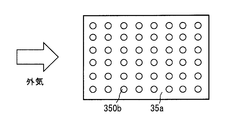
- the intake fin 350b is formed in a pin shape. This also increases the heat dissipating area of the electrode housing case 32 in the same manner as when plate-shaped straight fins are employed, and the effect of cooling the ozonizer 30 by the intake air flowing through the intake air passage 61a can be promoted.
- a guide plate 122 shown in FIG. 13 is attached to the housing 60. Specifically, the guide plate 122 is fixed to the housing bottom wall 60d by attaching the bracket 122c attached to the guide plate 122 to the housing bottom wall 60d.
- the guide plate 122 functions to collect the traveling wind on the portion of the housing 60 that is exposed to the traveling wind, that is, the portion of the housing bottom wall 60d that is exposed from the opening 121a. Specifically, the guide plate 122 rectifies and guides the traveling wind flowing along the storage floor plate 121 to the opening 121a.
- the guide plate 122 is a plate-like member disposed so as to face the storage floor plate 121. Between the guide plate 122 and the storage floor plate 121, a traveling wind passage 123 through which traveling wind flows in the vehicle front-rear direction is formed.
- the distance at which the upstream end 122 a of the traveling wind is separated from the storage floor 121 is larger than the distance at which the downstream end 122 b is separated from the storage floor 121. Therefore, the inlet of the traveling wind passage 123 is larger in the vertical direction than the outlet of the traveling wind passage 123. And the opening area of this inflow port is larger than the opening area of an outflow port.
- the present embodiment includes the guide plate 122 that collects the traveling wind on the portion of the housing 60 that is exposed to the traveling wind, that is, the portion that is exposed from the opening 121a. According to this, the traveling wind flowing along the storage floor plate 121 is guided to the opening 121 a by the guide plate 122. As a result, the amount of traveling wind flowing along the exposed portion of the housing 60 increases. In other words, the amount of traveling wind flowing into the housing bottom wall 60d and the traveling wind fins 63b increases. Therefore, the heat radiation amount of the ozonizer 30 can be improved.
- the opening part 121a is formed in the storage floor board 121, and a part of housing bottom wall 60d is exposed outside the vehicle from the opening part 121a.
- the opening part 121a is formed in the storage floor board 121, and a part of housing bottom wall 60d is exposed outside the vehicle from the opening part 121a.
- FIG. 14 forming the opening in the portion of the storage floor plate 121 facing the housing bottom wall 60d is abolished.
- the entire housing bottom wall 60d is in contact with the storage floor plate 121.
- the storage floor plate 121 is provided with a plurality of traveling wind fins 121b which are fins for radiating heat to the traveling wind.
- the shape, structure, and material of the traveling wind fin 121b are the same as the traveling wind fin 63b shown in FIGS.
- the storage floor plate 121 Since the storage floor plate 121 is disposed at a position exposed to the traveling wind in the vehicle 100, it is cooled by the traveling wind.
- the housing bottom wall 60d is in contact with the storage floor plate 121 that is cooled by the traveling wind. Therefore, after the heat generated in the electrode 31 is transmitted to the electrode housing case 32, it is transmitted from the ozonizer bottom wall 32d to the housing bottom wall 60d, and then from the housing bottom wall 60d to the storage floor plate 121 and is taken away by the traveling wind. It will be. That is, the outer surface 60da of the housing bottom wall 60d corresponds to a housing-side cooling surface that is cooled in contact with the storage floor plate 121 that is a portion of the vehicle 100 that is exposed to traveling wind.
- the guide plate 122 according to the third embodiment described above is attached to the housing 60
- the guide plate 1220 according to this embodiment is attached to the vehicle 100 by a bracket 1220c.
- the housing 60 has the housing bottom wall 60d that is cooled in contact with the storage floor plate 121 that is exposed to the traveling wind. Therefore, the heat generated in the electrode 31 is sequentially transmitted to the electrode housing case 32, the ozonizer bottom wall 32d, the housing bottom wall 60d, and the storage floor plate 121 and is taken away by the traveling wind. That is, the ozonizer 30 is cooled by the traveling wind. Therefore, since the ozonizer is cooled by both the outside air flowing through the intake air passage 61a and the traveling wind, the effect of suppressing the temperature rise of the ozonizer 30 can be promoted.
- a guide plate 1220 that collects the traveling wind to a predetermined air-cooled portion exposed to the traveling wind in the vehicle 100 is provided. According to this, the traveling wind flowing along the storage floor plate 121 is guided to the predetermined air-cooled portion by the guide plate 1220. Therefore, the amount of traveling wind flowing along the air-cooled portion of the storage floor board 121 increases. In other words, the amount of traveling wind flowing into the air-cooled portion of the storage floor plate 121 and the traveling wind fins 121b increases. Therefore, the heat radiation amount of the ozonizer 30 can be improved.
- a circuit board 410 In this embodiment, as shown in FIG. 15, a circuit board 410, a microcomputer 411, a communication interface 412, a switching element 413, and a circuit case 321 are provided.
- the microcomputer 411, the communication interface 412 and the switching element 413 are mounted on the circuit board 410.
- the circuit board 410 is accommodated in the circuit case 321.
- the switching element 413 is an electronic component such as a power MOS that switches on / off the energization of the electrode 31 and is controlled by the microcomputer 411 to operate.
- the communication interface 412 transmits and receives signals to and from the ECU 40.
- the circuit case 321 is disposed above the electrode housing case 32.
- the circuit case 321 and the electrode housing case 32 are connected by a pair of connection plates 322 in a state where the bottom wall 321d of the circuit case 321 and the ozonizer top wall 32u are separated from each other.
- the electrode housing case 32, the circuit case 321 and the connecting plate 322 are made of metal such as aluminum and are integrally formed by bending or welding.
- the case integrated in this way is referred to as a storage case 320.
- an intake air passage 322a that guides the outside air sucked from the outside air inlet 61b to the inlet 54a.
- an intake air passage 322 a is formed by a space surrounded by the bottom wall 321 d of the circuit case 321, the ozonizer top wall 32 u, and the pair of connecting plates 322.
- the portion of the storage case 320 that forms the intake air passage 322a corresponds to the suction duct member of the present disclosure.
- the switching element 413 and the circuit board 410 are in contact with the bottom wall 321d or the top wall 321u of the circuit case 321.
- the switching element 413 is in contact with the bottom wall 321d
- the circuit board 410 is in contact with the top wall 321u.
- the top wall 321u of the circuit case 321 is in contact with the housing top wall 60u.
- the bottom wall 321d of the circuit case 321 is provided with a plurality of circuit fins 321b that are located in the intake air passage 322a and radiate the heat of the circuit case 321 to the intake air.
- the circuit fins 321b have the same shape and material as the intake fins 35b.
- the ozonizer 30 can be cooled using the intake air flowing through the intake air passage 322a. Further, in the present embodiment, the circuit case 321 is also cooled by the intake air, so that it is possible to suppress the temperature rise of the electronic component that generates heat when the switching element 413 and the like are energized.
- the housing 60 that houses the ozonizer 30 and the blower 50 is used as a suction duct member that forms the suction air passage 61a.
- the housing 60 is abolished, and a dedicated intake duct member 600 that forms the intake air passage 600a is provided.
- the suction duct member 600 is connected to the suction duct 54.
- An outside air introduction duct 62 is connected to the outside air introduction port 600 c which is the other end of the suction duct member 600.
- the suction duct member 600 is formed with an opening 600b.
- the ozonizer ceiling wall 32u and the intake fin 35b are disposed in the opening 600b, and the ozonizer ceiling wall 32u and the intake fin 35b are exposed to the intake air passage 600a. Therefore, the electrode housing case 32 is cooled by the intake air flowing through the intake air passage 600a.
- the ozonizer 30 can be cooled using the intake air flowing through the intake air passage 600a.
- the reducing agent addition device having a function of supplying ozone provides the ozone supply device.
- the ozone supply device shown in FIG. 17 is provided, which is a device in which the reaction vessel 20, the heater 21, and the injection valve 22 shown in FIG.
- the ozone supply device includes an ozonizer 30, a blower 50, a supply pipe 26, a connection pipe 23, an on-off valve 26v, and an ECU 40.
- the NOx purification device 12 shown in FIG. 1 employs a reduction catalyst that selectively reacts the reducing agent with NOx in the presence of O 2 .
- the NOx purification device 12A according to the present embodiment employs a reduction catalyst that stores NOx in a lean environment in the presence of O 2 and reacts a reducing agent with NOx in a rich environment.
- an occlusion reduction catalyst using platinum and barium supported on a carrier can be cited.
- the processing content shown in FIG. 10 is changed as follows. That is, the determinations in steps S11 and S12 shown in FIG. 10 are abolished, and the control of reducing agent supply in steps S16, S17, and S18 is abolished. If it is determined in step S13 that the catalyst temperature Tcat is higher than the third predetermined temperature T3, the full stop control in step S19 is performed.
- the ozonizer 30 is cooled using the intake air by disposing at least a part of the ozonizer 30 in the intake air passage. Can be made.
- the upper end of the intake fin 35b is separated from the housing top wall 60u.
- the upper end of the intake fin 35b may be brought into contact with the housing top wall 60u. According to this, the cooling of the ozonizer 30 can be promoted by heat transfer from the intake fin 35b to the housing ceiling wall 60u.
- At least one of the running wind fins 63b and 121b, the intake fin 35b, and the circuit fin 321b may be eliminated.
- the guide plate 122 shown in FIG. 13 and the guide plate 1220 shown in FIG. 14 may be eliminated.
- the ozonizer 30 and the blower 50 are arranged in the storage 104 of the trunk room 103.
- the ozonizer 30 may be disposed at a place other than the storage case 104 such as below the floor plate 120. In other words, it may be arranged in a space communicating with the boarding room 102 such as the trunk room 103 or in a space not communicating with the boarding room 102 such as below the floor board 120.
- the guide plate 122 is attached to the housing 60, but may be attached to the vehicle 100 such as the storage floor plate 121.
- the ozone supply device may be applied to a combustion system including a catalyst that oxidizes and purifies CO and HC (predetermined components) in exhaust gas.
- a catalyst that oxidizes and purifies CO and HC (predetermined components) in exhaust gas.
- the oxidation function of the oxidation catalyst can be enhanced, which is useful.
- an ozone supply device is applied to a compression self-ignition diesel engine, and light oil used as a fuel for combustion is used as a reducing agent.
- an ozone supply device may be applied to an ignition ignition type gasoline engine, and gasoline used as a fuel for combustion may be used as a reducing agent.
- Means and / or functions provided by the ECU 40 as the control device can be provided by software recorded in a substantial storage medium and a computer that executes the software, only software, only hardware, or a combination thereof.
- the controller is provided by a circuit that is hardware, it can be provided by a digital circuit including a number of logic circuits, or an analog circuit.
Landscapes
- Engineering & Computer Science (AREA)
- Chemical & Material Sciences (AREA)
- Combustion & Propulsion (AREA)
- Mechanical Engineering (AREA)
- General Engineering & Computer Science (AREA)
- Organic Chemistry (AREA)
- Chemical Kinetics & Catalysis (AREA)
- Inorganic Chemistry (AREA)
- Health & Medical Sciences (AREA)
- General Health & Medical Sciences (AREA)
- Toxicology (AREA)
- Exhaust Gas After Treatment (AREA)
- Exhaust Gas Treatment By Means Of Catalyst (AREA)
- Oxygen, Ozone, And Oxides In General (AREA)
Abstract
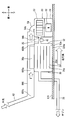
オゾン供給装置は、オゾナイザ(30)および送風機(50)を備えるとともに、吸入ダクト部材としてのハウジング(60)を備える。オゾナイザ(30)は、放電によりオゾンを生成する電極(31)を有する。送風機(50)は、空気を吸入する吸入口(54a)、および吸入口(54a)から吸入した空気を吹き出す吹出口(54b)を有し、吹出口(54b)から吹き出された空気を電極(31)へ供給するとともに、放電により生成されたオゾンを排気通路へ送風する。ハウジング(60)は、吸入口(54a)へ空気を導く吸入空気通路(61a)を形成する。そして、オゾナイザ(30)の少なくとも一部が吸入空気通路(61a)に配置されている。
Description
本願は、2015年9月8日に出願された日本国特許出願第2015-176931号に基づくものであり、この開示をもってその内容を本明細書中に開示したものとする。
本開示は、オゾンを生成して内燃機関の排気通路へ供給するオゾン供給装置に関する。
特許文献1には、内燃機関の排気に含まれるNOxを吸着する吸着剤および還元触媒を備えた浄化装置が開示されている。この浄化装置では、触媒が活性化していない低温時にはNOxを吸着剤に吸着させ、活性化温度に達している時には還元剤を排気通路へ供給して、触媒上でNOxを還元させて浄化させる。
さらに特許文献1には、排気通路のうち吸着剤の上流側へオゾンを供給するオゾン供給装置が開示されている。オゾン供給装置は、放電によりオゾンを生成する電極を有したオゾナイザと、空気を電極へ供給するとともに生成されたオゾンを排気通路へ送風する送風機と、を備える。そして、上述した低温時に排気通路へオゾンを供給すれば、排気中のNOがNO2に酸化される。NO2はNOに比べて吸着剤へ吸着しやすい性質があるので、オゾン供給によりNOx吸着量の増大が図られる。
また、この種のオゾン供給装置は、NOx吸着量増大の他にも各種の用途がある。例えば、ディーゼルパティキュレートフィルタ(以下、DPF)に捕捉された微粒子を燃焼させてDPFを再生させる時に、排気通路へオゾンを供給すれば、上記燃焼を促進させて再生を促進できる。
さて、放電によりオゾンを生じさせると電極等で発熱が生じるため、空冷ファンを用いてオゾナイザを冷却する等、放熱に配慮することが要求される。しかしながら、車両への搭載スペースに限りがあるので、上述した空冷ファンを設けるとオゾン供給装置の大型化を招き、車両への搭載が困難になる。
本開示は、上記問題を鑑みてなされたもので、その目的は、装置の大型化を抑制しつつオゾナイザの放熱性向上を図ったオゾン供給装置を提供することにある。
上記の目的を達成するために、本開示では、車両に搭載され、内燃機関の排気通路へオゾンを供給するオゾン供給装置において、
放電によりオゾンを生成する複数の電極を有したオゾナイザと、
空気を吸入する吸入口、および吸入口から吸入した空気を吹き出す吹出口を有し、吹出口から吹き出された空気を複数の電極へ供給するとともに、放電により生成されたオゾンを排気通路へ送風する送風機と、
吸入口へ空気を導く吸入空気通路を形成する吸入ダクト部材と、を備え、
オゾナイザの少なくとも一部が吸入空気通路に配置されているオゾン供給装置を提供する。
放電によりオゾンを生成する複数の電極を有したオゾナイザと、
空気を吸入する吸入口、および吸入口から吸入した空気を吹き出す吹出口を有し、吹出口から吹き出された空気を複数の電極へ供給するとともに、放電により生成されたオゾンを排気通路へ送風する送風機と、
吸入口へ空気を導く吸入空気通路を形成する吸入ダクト部材と、を備え、
オゾナイザの少なくとも一部が吸入空気通路に配置されているオゾン供給装置を提供する。
このオゾン供給装置によれば、送風機の吸入口へ空気を導く吸入空気通路に、オゾナイザの少なくとも一部が配置されているので、吸入空気でオゾナイザが冷却される。よって、排気通路へオゾンを供給する送風機をオゾナイザ冷却に利用できるので、該送風機とは別にオゾナイザ冷却専用の空冷ファンを設けることを不要にできる。したがって、装置の大型化を抑制しつつオゾナイザの放熱性向上を図ることができる。
以下、図面を参照しながら発明を実施するための複数の形態を説明する。各形態において、先行する形態で説明した事項に対応する部分には同一の参照符号を付して重複する説明を省略する場合がある。各形態において、構成の一部のみを説明している場合は、構成の他の部分については先行して説明した他の形態を参照し適用することができる。
(第1実施形態)
図1に示す燃焼システムは、以下に詳述する内燃機関(以下、エンジン10)、過給機11、NOx浄化装置12、微粒子捕集装置(以下、DPF13)、および還元剤添加装置を備える。燃焼システムは車両に搭載されたものであり、当該車両は、エンジン10の出力を駆動源として走行する。エンジン10は、圧縮自着火式のディーゼルエンジンであり、燃焼に用いる燃料には、炭化水素化合物である軽油を用いている。エンジン10は、基本的にはリーン状態で燃焼させるように作動する。つまり、燃焼室に噴射された燃料と燃焼室に吸入される空気との比率である空燃比が、空気過剰に設定された状態で燃焼(つまり、リーン燃焼)させている。
図1に示す燃焼システムは、以下に詳述する内燃機関(以下、エンジン10)、過給機11、NOx浄化装置12、微粒子捕集装置(以下、DPF13)、および還元剤添加装置を備える。燃焼システムは車両に搭載されたものであり、当該車両は、エンジン10の出力を駆動源として走行する。エンジン10は、圧縮自着火式のディーゼルエンジンであり、燃焼に用いる燃料には、炭化水素化合物である軽油を用いている。エンジン10は、基本的にはリーン状態で燃焼させるように作動する。つまり、燃焼室に噴射された燃料と燃焼室に吸入される空気との比率である空燃比が、空気過剰に設定された状態で燃焼(つまり、リーン燃焼)させている。
過給機11は、タービン11a、回転軸11bおよびコンプレッサ11cを備える。タービン11aは、エンジン10の排気通路10exに配置され、排気の運動エネルギにより回転する。回転軸11bは、タービン11aおよびコンプレッサ11cの各インペラを結合することで、タービン11aの回転力をコンプレッサ11cに伝達する。コンプレッサ11cは、エンジン10の吸気通路10inに配置され、吸気を圧縮してエンジン10へ過給する。
吸気通路10inのうちコンプレッサ11cの下流側には、コンプレッサ11cで圧縮された吸気(つまり、加圧空気)を冷却する、図示しない冷却器が配置されている。冷却器により冷却された圧縮吸気は、図示しないスロットルバルブにより流量調整され、エンジン10が有する複数の燃焼室へ分配される。排気通路10exのうちタービン11aの下流側にはNOx浄化装置12が配置され、さらにその下流側にはDPF13が配置されている。DPF13は、排気に含まれている微粒子を捕集する。
排気通路10exのうちNOx浄化装置12の上流側には、還元剤添加装置の接続管23が接続されている。この接続管23から排気通路10exへ、還元剤添加装置により生成された改質燃料が還元剤として添加される。改質燃料とは、還元剤として用いる炭化水素化合物(燃料)を部分的に酸化して、アルデヒド等の部分酸化炭化水素に改質したものである。また、還元剤添加装置は、接続管23から排気通路10exへオゾンを供給する機能を有しており、オゾン供給装置を提供する。
NOx浄化装置12は、ハウジング内にハニカム状の担体を収容して構成される。担体の表面にはコーティング材が設けられており、そのコーティング材には還元触媒が担持されている。NOx浄化装置12は、排気中のNOxを還元触媒上で改質燃料と反応させてN2に還元することで、排気に含まれているNOxを浄化する。なお、排気中にはNOxの他にO2(酸素)も含まれているが、改質燃料はO2存在下においてNOxと選択的に反応する。
還元触媒には、NOxを吸着する機能を有したものが用いられている。詳細には、還元反応が可能となる活性化温度よりも触媒温度Tcatが低い場合に、還元触媒は排気中のNOxを吸着する機能を発揮する。例えば、担体に担持された銀アルミナによる還元触媒により、NOx吸着機能を有したNOx浄化装置12が提供される。詳細には、担体表面にコーティングされたアルミナに、還元触媒としての銀を担持させた構造である。吸着されていたNOxは、触媒温度Tcatが活性化温度以上の場合には、還元触媒から脱離する。そして、脱離したNOxは改質燃料により還元されて浄化される。さらに、この還元触媒は、NOx吸着機能に加えて活性酸素を吸着する機能をも有している。
次に、改質燃料またはオゾンを生成して接続管23から排気通路10exへ添加する還元剤添加装置について説明する。還元剤添加装置は、以下に詳述する反応容器20、ヒータ21、噴射弁22、オゾナイザ30、送風機50、接続管23、供給管26、開閉弁26vおよび電子制御装置(以下、ECU40)を備える。
オゾナイザ30は、放電によりオゾンを生成する電極31と、電極31を内部に収容する電極収容ケース32とを有する。電極収容ケース32は内部に流通路32aを形成し、流通路32aには複数の電極31が配置されている。これらの電極31は、互いに平行に対向するように配置された平板形状であり、高電圧が印加される電極と接地電圧の電極とが交互に配置されている。電極31への電圧印加は、ECU40が備えるマイクロコンピュータ(以下、マイコン41)により制御される。オゾナイザ30の電極収容ケース32には、送風機50により送風された空気が流入する。
図5に示されるように、送風機50は、ブロワケース51、電動モータ52およびファン53を備える。ファン53はブロワケース51内に配置され、電動モータ52により回転駆動する。ブロワケース51には、空気を吸入する吸入口54aが形成された吸入ダクト54が設けられている。また、ブロワケース51には、吸入口54aから吸入した空気を吹き出す吹出口54bが形成されている。送風機50は遠心式であり、ファン53に対して回転軸方向に対向する位置に吸入口54aが形成され、ファン53に対して回転径方向に対向する位置に吹出口54bが形成されている。ファン53を回転駆動させると、吸入口54aからブロワケース51内に空気が吸入され、ファン53により圧縮されて吹出口54bから吹き出される。
吹出口54bには送風ダクト25が接続され、吹出口54bから吹き出された空気は、送風ダクト25を通じてオゾナイザ30へ供給される。送風機50から吹き出された空気は、電極収容ケース32の内部、つまり電極31が配置されている流通路32aへ供給される。
送風機50によりオゾナイザ30へ供給される空気の送風量は、電動モータ52への通電をマイコン41が制御することで調節される。例えば、電動モータ52への供給電力量をマイコン41がデューティ制御することで送風量を制御する。オゾナイザ30へ送風された空気は、電極収容ケース32内の流通路32aに流入し、電極31間の通路である電極間通路31aを流通する。
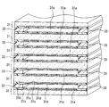
図2に示されるように、電極31は、絶縁基板31b、電極板31cおよび絶縁保護膜31dを備える。絶縁基板31bは、セラミック製であり、電極板31cを保持する。電極板31cに高電圧が印加されることにより電極間通路31aにおいて放電させる。絶縁保護膜31dは、電極板31cが電極間通路31aに露出しないように、電極間通路31a側から電極板31cの表面を覆う。
複数の電極31は、スペーサ33を介して積層配置されている。これにより、平板形状の電極31が互いに平行に対向するように配置される。また、一対の電極31はスペーサ33により所定の間隔に保たれ、電極31間に電極間通路31aが形成される。オゾナイザ30は、一対の電極31を複数組備えている。
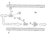
電極31へ電圧を印加すると、図3の符号(1)に示すように、電極31から放出された電子が、送風機50により送風されてくる空気に含まれる酸素分子に衝突する。すると、符号(2)に示すように、酸素分子は電離して活性酸素の状態になる。この活性酸素は、符号(3)に示すように酸素分子と反応し、符号(4)に示すようにて酸化してオゾンが生成される。要するに、電極31に電圧を印加して送風機50を作動させた状態にすれば、各々の電極31間において、高活性物質であるオゾンが生成される。生成されたオゾンは、送風機50の送風圧力により電極間通路31aおよび流通路32aから流出する。
図1の説明に戻り、オゾナイザ30は、供給管26を介して反応容器20に接続される。供給管26には、電磁駆動式の開閉弁26vが取り付けられている。開閉弁26vは反応容器20の上流側に位置する。開閉弁26vの開閉駆動はマイコン41により制御される。詳細には、開閉弁26vの弁体は全開位置と全閉位置とに切り替え制御され、供給管26の内部通路である供給通路26aを開閉する。
したがって、送風機50を駆動させて開閉弁26vを開弁作動させると、オゾナイザ30から流出したオゾンを含む空気は、供給管26、反応容器20および接続管23を順に流通して排気通路10exへ流入することとなる。また、排気圧力が高い場合に開閉弁26vを閉弁させることで、排気が供給通路26aを逆流してオゾナイザ30へ流れ込むことを抑制できる。よって、排気に含まれる煤等の異物が電極31に付着することを抑制でき、異物付着により放電が妨げられることを抑制できる。
反応容器20には、ヒータ21および噴射弁22が取り付けられており、反応容器20の内部には、流入口20inおよび流出口20outと連通する反応室20aが形成されている。ヒータ21は、通電により発熱する発熱部を有し、発熱部への通電はマイコン41により制御される。具体的には、発熱部への電力供給量をマイコン41がデューティ制御することにより、発熱量が制御される。発熱部は反応室20aに配置され、噴射弁22から反応室20aへ噴射された燃料を加熱する。反応室20aの温度は反応室温度センサ27により検出される。反応室温度センサ27は、検出した反応室温度ThをECU40へ出力する。
噴射弁22は、噴孔が形成されたボデー、電気アクチュエータおよび弁体を有する。電気アクチュエータを通電オンさせると、弁体が開弁作動して噴孔から反応室20aへ燃料が噴射され、通電オフさせると弁体が閉弁作動して燃料噴射が停止される。マイコン41は、電気アクチュエータへの通電を制御することで、反応室20aへの単位時間当たりの燃料噴射量を制御する。図示しない燃料タンク内の液体燃料は、図示しない燃料ポンプにより噴射弁22へ供給される。燃料タンク内の燃料は、先述した燃焼用の燃料としても用いられており、エンジン10の燃焼に用いる燃料と、還元剤として用いる燃料は共用される。
噴射弁22から反応室20aへ噴射された燃料は、ヒータ21に衝突し、加熱されて気化する。気化した燃料は、流入口20inから反応室20aへ流入した空気と混合される。その結果、空気中の酸素により気体燃料が部分的に酸化され、アルデヒド等の部分酸化炭化水素に改質される。このように改質された気体燃料(つまり、改質燃料)は、接続管23を通じて排気通路10exに流入する。
反応室20aでは以下に詳述する冷炎反応が生じている。この冷炎反応は、流入口20inから流入する空気中の酸素により気体燃料が部分的に酸化される反応である。このように部分的に酸化された燃料(つまり、改質燃料)の具体例として、燃料(炭化水素化合物)の一部がアルデヒド基(つまり、CHO)に酸化された状態の部分酸化物(例えば、アルデヒド)が挙げられる。また、反応室20aへ供給される空気にオゾンが多く含まれているほど、燃料が部分酸化される反応が促進される。つまり、部分酸化されずに反応室20aから流出してしまう燃料(つまり、非改質燃料)が少なくなる。
次に、図4を用いて、還元剤添加装置の車両100への搭載位置を説明する。なお、図中の前後方向を示す矢印は、車両100の前後方向を示し、図中の上下方向を示す矢印は重力方向を示す。車両100は、エンジンルーム101、搭乗室102、およびトランクルーム103を有する。エンジンルーム101にはエンジン10が配置されている。搭乗室102には、車両乗員が座る座席102aやステアリング102b、インストルメントパネル(以下、インパネ102c)等が配置されている。インパネ102cには、図示しない空調装置で温度調整された空調風を搭乗室102へ吹き出すための、空調風吹出口102dが設けられている。
トランクルーム103は、乗員が持ち込んだ荷物を置くスペースであり、搭乗室102と連通している。トランクルーム103には、トランクルーム103を上下に区画する仕切板140が設置されている。トランクルーム103のうち仕切板140の下方部分のスペースは、スペアタイヤや工具等を収納可能な収納庫104として機能する。収納庫104は、本開示のの区画室に相当する。
車両100は、金属製の板部材であるファイアウォール110、床板120および天板130を備える。ファイアウォール110は、エンジンルーム101と搭乗室102とを仕切る。床板120および天板130の各々は、搭乗室102およびトランクルーム103の床および天井を形成する。なお、搭乗室102およびトランクルーム103の側壁は、図示しない側板およびドアにより形成される。
反応容器20および開閉弁26vはエンジンルーム101に配置されている。オゾナイザ30および送風機50は収納庫104に配置されている。詳細には、床板120のうち収納庫104を形成する部分である収納床板121の上にハウジング60が設置され、そのハウジング60内にオゾナイザ30および送風機50が収容されている。オゾナイザ30および送風機50は車両前後方向に並べて配置されており、送風機50は、オゾナイザ30に対して車両後方側、つまり搭乗室102から遠い側に配置されている。
オゾナイザ30で生成されたオゾンを反応容器20へ供給する供給管26は、収納庫104からエンジンルーム101まで、床板120の下方に沿って延びている。接続管23はエンジンルーム101に配置され、改質燃料またはオゾンは、エンジンルーム101において接続管23から排気通路10exへ供給される。
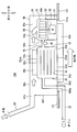
図5に示すように、ハウジング60は、内部の空間を包囲する複数の壁からなる箱形を呈し、樹脂または金属の成型品で形成されている。ハウジング60は、例えば、上下方向に扁平な直方体となっており、6面、即ち、ハウジング天壁60u、ハウジング底壁60d、ハウジング側壁60s、ハウジング前壁60f、およびハウジング後壁60bを有する6面体形状である。
ハウジング天壁60uは、ハウジング60の上側の面を形成する壁であり、前後方向に長辺を有する長方形の壁となっている。ハウジング底壁60dは、ハウジング60の下側の面を形成する壁であり、ハウジング天壁60uと同様の形状を有している。
一対のハウジング側壁60sは、ハウジング60の左右側の面を形成する壁であり、前後方向に長辺を有する細長い長方形の壁であり、互いに向かい合う位置関係にある。ハウジング前壁60fおよびハウジング後壁60bは、ハウジング60の前後側の面を形成する壁であり、互いに向かい合う位置関係にある。また、ハウジング前壁60fおよびハウジング後壁60bは、ハウジング側壁60sに対して直交する壁となっている。
電極収容ケース32のうちハウジング天壁60uと対向する部分をオゾナイザ天壁32uと呼び、ハウジング底壁60dと対向する部分をオゾナイザ底壁32dと呼ぶ。電極収容ケース32は、内部の空間を包囲する複数の壁からなる箱形を呈し、アルミニウム板または鉄板の成型品で形成されている。
トランクルーム103は搭乗室102と連通しているため、空調風吹出口102dから搭乗室102へ吹き出された空調風は、トランクルーム103にも流入する。そして、ハウジング60には外気導入口61bが形成され、この外気導入口61bには外気導入ダクト62が接続されている。外気導入ダクト62は、トランクルーム103や搭乗室102の外部の空気、つまり空調されていない車外空気(以下、外気)を外気導入口61bへ導く。
内部空間61は、外気導入口61b以外は密閉されているので、送風機50を駆動させると、外気導入口61bから内部空間61へ外気が導入され、内部空間61へ導入された外気は吸入口54aからブロワケース51へ吸入される。
外気導入口61bおよび吸入口54aはハウジング天壁60uの近傍に配置されている。これにより、外気導入口61bから導入された外気は、ハウジング天壁60uに沿って車両前方から後方へ向けて流れた後、吸入口54aへ吸入される。外気導入口61bは、ハウジング前壁60fのうち、吸入口54aと対向する位置に形成されている。
そして、内部空間61のうち、ハウジング天壁60uとオゾナイザ天壁32uとの間に位置する空間は、吸入口54aへ空気を導く吸入空気通路61aに相当する。また、ハウジング60の一部であるハウジング天壁60uおよび一対のハウジング側壁60sが、吸入空気通路61aを形成する吸入ダクト部材に相当する。
吸入空気通路61aを流れる外気は、ハウジング天壁60u、ハウジング側壁60sおよびオゾナイザ天壁32uに沿って流れると言える。ここで、電極31に電圧印加して放電を生じさせると電極31が発熱するが、その熱は、電極収容ケース32に伝わった後、オゾナイザ天壁32uに沿って流れる外気により奪われる。つまり、オゾナイザ30は外気により冷却される。よって、オゾナイザ天壁32uの外面32uaは、吸入空気通路61aに面して冷却される通路冷却面に相当する。
さらに、オゾナイザ天壁32uには、吸入空気通路61aに位置して電極収容ケース32の熱を吸入空気へ放熱する吸気用フィン35bが複数設けられている。図6および図7に示すように、複数の吸気用フィン35bは、基板35aと一体に形成されたアルミニウム等の金属製であり、基板35aはオゾナイザ天壁32uに溶接またはボルト等で取り付けられている。電極31の熱は、電極収容ケース32、基板35aおよび吸気用フィン35bへ順に移動し、吸気用フィン35bから外気へ放熱される。吸気用フィン35bは、吸入空気通路61aが延びる方向に沿って延びる板形状のストレートフィンである。吸気用フィン35bは、基板35a上において、吸入空気通路61aを流れる外気の流れ方向に対して交差する方向に、所定ピッチで平行に複数並べて配置されている。
収納床板121には開口部121aが形成されている。ハウジング底壁60dの一部は、開口部121aから車外に露出し、車両100の走行時には走行風に晒される。換言すれば、ハウジング底壁60dが走行風に晒される位置となるよう、ハウジング60は車両100に搭載されている。車両100を走行させると、収納床板121に沿って流れる走行風の一部は、開口部121aから露出するハウジング底壁60dに沿って流れる。
このように、ハウジング底壁60dが走行風に晒されることで、ハウジング60は走行風で冷却される。そして、オゾナイザ底壁32dはハウジング底壁60dに接触しているので、電極31で生じた熱は、電極収容ケース32に伝わった後、オゾナイザ底壁32dからハウジング底壁60dに伝わり、走行風により奪われる。つまり、オゾナイザ30は走行風により冷却される。よって、オゾナイザ底壁32dの外面32daは、ハウジング底壁60dに接触して冷却される接触冷却面に相当する。
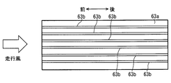
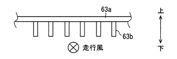
さらに、ハウジング底壁60dには、走行風へ放熱するフィンである走行風用フィン63bが複数設けられている。図8および図9に示すように、複数の走行風用フィン63bは、基板63aと一体に形成されたアルミニウム等の金属製であり、基板63aはハウジング底壁60dに溶接またはボルト等で取り付けられている。電極31の熱は、電極収容ケース32、基板63aおよび走行風用フィン63bへ順に移動し、走行風用フィン63bから走行風である外気へ放熱される。走行風用フィン63bは、車両前後方向に沿って延びる板形状のストレートフィンである。走行風用フィン63bは、基板63a上において、車両前後方向に対して交差する方向に、所定ピッチで平行に複数並べて配置されている。
ハウジング60を樹脂で形成した場合には、ハウジング60の一部分を金属製にして、オゾナイザ30および送風機50で発生した熱の放熱を促進させることが望ましい。具体的には、ハウジング60のうち開口部121aから車外に露出する部分を金属製にすることが望ましい。例えば、ハウジング底壁60dの全体、またはハウジング底壁60dのうち開口部121aから露出する部分を、部分的に金属製にすることが望ましい。
ECU40が備えるマイコン41は、プログラムを記憶する記憶装置と、記憶されたプログラムにしたがって演算処理を実行する中央演算処理装置と、を備える。ECU40は、単位時間当りのエンジン回転数およびエンジン負荷等の各種検出値に基づき、エンジン10の作動を制御する。
エンジン回転数は、エンジン10の出力軸近傍に取り付けられたクランク角センサ14により検出される。エンジン負荷を表わす物理量としては、吸気圧、吸気量、アクセルペダル踏込量等が挙げられる。吸気圧は、吸気通路10inのうちコンプレッサ11cの下流側部分に取り付けられた吸気圧センサ15により検出される。吸気量は、吸気通路10inのうちコンプレッサ11cの上流側部分に取り付けられたエアフロメータ16により検出される。アクセルペダル踏込量は、アクセルペダルに取り付けられたアクセルセンサ17により検出される。
ECU40は、エンジン回転数やエンジン負荷等のエンジン10の作動状態の検出値に加え、反応室温度センサ27、触媒温度センサ42、排気温度センサ43、排気圧センサ44、送風量センサ45および送風圧センサ46により検出された物理量を取得する。そして、これらの物理量に基づき、還元剤添加装置の作動を制御する。
触媒温度センサ42は、NOx浄化装置12に取り付けられ、還元触媒の雰囲気温度(つまり、触媒温度Tcat)を検出する。排気温度センサ43は、排気通路10exに取り付けられて排気温度を検出する。排気圧センサ44は、排気通路10exに取り付けられて排気圧力を検出する。排気温度センサ43および排気圧センサ44は、排気通路10exのうちNOx浄化装置12の上流側、かつタービン11aの下流側に取り付けられている。送風量センサ45は、供給管26のうちオゾナイザ30の上流側かつ送風機50の下流側に取り付けられており、送風機50により送風される空気の量である送風量を検出する。送風圧センサ46は、供給管26のうち反応容器20の上流側かつオゾナイザ30の下流側に取り付けられており、供給管26内の空気の圧力である送風圧力を検出する。
概略、ECU40は以下のように還元剤添加装置の作動を制御する。すなわち、反応室温度Thに基づき、排気通路10exへ還元剤を供給する還元剤供給制御と、排気通路10exへオゾンを供給するオゾン供給制御とを切り替える。また、還元剤添加制御を実施するにあたり、反応室温度Thに基づき、強酸化制御、弱酸化制御および酸化停止制御を切り替える。
具体的には、図10に示す手順のプログラムをマイコン41が所定周期で繰り返し実行することで、還元剤添加装置の作動を制御する。先ず、図10のステップS10において、エンジン10が運転中であるか否かを判定する。運転中でないと判定された場合、浄化対象となるNOxが排気通路10exに存在しないとみなし、ステップS19において還元剤添加装置の作動を停止させる全停止制御を実施する。全停止制御は、オゾンおよび還元剤のいずれについても排気通路10exへの供給を停止させる制御である。つまり、送風機50、オゾナイザ30、ヒータ21、噴射弁22を全て停止させ、開閉弁26vを閉弁作動させる。
一方、ステップS10によりエンジン10が運転中であると判定された場合、ステップS11において、触媒温度Tcatが第1所定温度T1より高温であるか否かを判定する。第1所定温度T1より低温であると判定された場合、続くステップS12において、触媒温度Tcatが第2所定温度T2より高温であるか否かを判定する。第2所定温度より低温であると判定された場合、続くステップS13において、触媒温度Tcatが第3所定温度T3より高温であるか否かを判定する。第3所定温度より低温であると判定された場合、続くステップS14において、触媒温度Tcatが第4所定温度T4より高温であるか否かを判定する。
第1所定温度T1および第2所定温度T2は、第3所定温度T3より高温に設定されている。第1所定温度T1は、第2所定温度T2より高温に設定されている。例えば、第3所定温度T3が200℃である場合、第2所定温度T2を350℃、第1所定温度T1を400℃に設定する。ここで、還元触媒の第3所定温度T3とは、還元触媒上でNOxを還元浄化できる最低温度(つまり、活性化温度)のことである。第4所定温度T4とは、触媒に活性酸素を吸着できる最低温度のことであり、第3所定温度よりも低温に設定されている。
ステップS11、S12、S13、S14の判定により、触媒温度Tcatが第4所定温度T4より低温と判定された場合、ステップS19にて先述した全停止制御を実施する。触媒温度Tcatが第4所定温度T4より高温、かつ第3所定温度T3より低温と判定された場合、ステップS15にてオゾン供給制御を実施する。触媒温度Tcatが第3所定温度T3より高温、かつ第2所定温度T2より低温と判定された場合、ステップS16にて強酸化制御を実施する。触媒温度Tcatが第2所定温度T2より高温、かつ第1所定温度T1より低温と判定された場合、ステップS17にて弱酸化制御を実施する。触媒温度Tcatが第1所定温度T1より高温と判定された場合、ステップS18にて酸化停止制御を実施する。
さて、噴射した燃料と供給される空気の比率である当量比、および噴射された燃料の雰囲気温度を所定範囲に調整すると、噴射された燃料は、熱炎反応に達することなく冷炎反応する。熱炎反応とは、燃料が完全燃焼して二酸化炭素および水が生成される反応である。冷炎反応とは、空気中の酸素により燃料が部分的に酸化される反応である。このように部分的に酸化された燃料である改質燃料の具体例として、炭化水素化合物である燃料の一部が、アルデヒド基(CHO)に酸化された状態の部分酸化物(例えばアルデヒド)が挙げられる。この知見に基づいて、ステップS16、S17、S18に係る強酸化制御、弱酸化制御、酸化停止制御では、改質燃料が触媒に供給されるように、当量比および雰囲気温度を調整している。
ステップS16に係る強酸化制御では、オゾナイザ30で生成されたオゾン、空気中の酸素、およびヒータ21により気化された燃料が混合され、オゾンが存在する環境下で燃料が冷炎反応して部分酸化される。
具体的には、反応室温度センサ27による検出値である反応室温度Thが、予め設定しておいた目標温度Ttrgと一致するよう、ヒータ21をフィードバック制御する。目標温度Ttrgは、熱炎反応に達することなく冷炎反応させる雰囲気温度(例えば370℃)となるように設定されている。
さらに、上記強酸化制御では、NOx浄化装置12へ流入したNOxの全てを還元するにあたり、過不足なくNOx浄化装置12へ供給するための還元剤添加量を、目標燃料量Ftrgとして算出する。例えば、単位時間当たりにNOx浄化装置12へ流入するNOx流入量および触媒温度Tcatに基づき、目標燃料量Ftrgを設定する。NOx流入量は、エンジン10の運転状態に基づき推定される。NOx流入量が多いほど、目標燃料量Ftrgを増大させる。また、触媒温度Tcatに応じて還元触媒上でNOxが還元される量(つまり還元力)が異なってくるので、触媒温度Tcatによる還元力の違いに応じて目標燃料量Ftrgを設定する。そして、算出した目標燃料量Ftrgに基づき、噴射弁22の作動を制御して燃料噴射を実施する。
さらに、上記強酸化制御では、反応室温度Thに基づき、冷炎反応を生じさせるように目標当量比φtrgを算出する。そして、目標当量比φtrgおよび目標燃料量Ftrgに基づき目標空気量Atrgを算出し、この目標空気量Atrgに基づき、送風機50の作動を制御する。上述のごとく反応室温度Thおよび当量比を制御することで、冷炎反応を生じさせて改質燃料が生成される。
さらに、上記強酸化制御では、開閉弁26vを開弁制御するとともに、反応容器20内での燃料の濃度に応じて、オゾナイザ30への供給電力を制御する。詳細には、目標燃料量Ftrgに基づき目標オゾン量Otrgを算出する。具体的には、反応室20aにおけるオゾン濃度の燃料濃度に対する比率が所定値(例えば0.2)となるように、目標オゾン量Otrgを算出する。例えば、所定時間(例えば0.02秒)内に冷炎反応を完了させるよう、上記比率を設定する。また、還元触媒が低温であるほど目標オゾン量Otrgを増加させるように設定する。
そして、目標空気量Atrgおよび目標オゾン量Otrgに基づき、オゾナイザ30への目標通電量Ptrgを算出する。具体的には、目標空気量Atrgが多いほど、電極間通路31aでの空気の滞留時間が短くなるので、目標通電量Ptrgを大きくする。また、目標オゾン量Otrgが多いほど、目標通電量Ptrgを大きくする。次に、目標通電量Ptrgに基づき、オゾナイザ30への通電量を制御する。具体的には、目標通電量Ptrgが大きいほど、オゾナイザ30への通電デューティ比を増大させる。或いは、今回の通電終了から次回の通電開始までのインターバルを短くする。
このような処理を実行することにより、オゾンが生成され、そのオゾンが反応容器20内に供給されるので、冷炎反応の開始時期の早期化と冷炎反応時間の短縮化が図られる。よって、反応容器20内での燃料の滞留時間が短くなるように反応容器20を小型化しても、上記滞留時間内に冷炎反応が完了するようにできる。よって、反応容器20の小型化を図ることができる。
このように、ステップS16の強酸化制御によれば、オゾンが存在する環境下で燃料が部分酸化される。これに対し、ステップS17による弱酸化制御では、オゾナイザ30を停止させてオゾン生成を停止させることで、オゾンが存在しない環境下で燃料が部分酸化される。つまり、ヒータ制御、燃料噴射制御、エアポンプ制御および開弁制御を実施する。但し、放電制御を実施せず、オゾナイザ30への通電を停止させてオゾン生成を停止させる。
ステップS17の弱酸化制御によれば、ヒータ制御による加熱を実施して部分酸化させている。これに対し、ステップS18による酸化停止制御では、オゾナイザ30およびヒータ21を停止させて、オゾン生成と燃料加熱を停止させる。これにより、酸素やオゾンによる酸化が為されることなく部分酸化していない燃料が、排気通路10exへ添加され、排気通路10exまたはNOx浄化装置12の内部で高温の排気に晒されて部分酸化する。
ステップS18による酸化停止制御では、燃料噴射制御、エアポンプ制御および開弁制御を実施する。但し、放電制御を実施せず、オゾナイザ30への通電を停止させてオゾン生成を停止させ、かつ、ヒータ制御を実施せず、ヒータ21への通電を停止させて燃料の加熱を停止させる。
図10のステップS15に係るオゾン供給制御では、概略、ヒータ21への通電を停止させるとともに、噴射弁22への通電を停止させて燃料噴射を停止させた状態で、オゾナイザ30でオゾンを生成する。そして、開閉弁26vを開弁作動させた状態で送風機50を作動させることで、生成したオゾンを、供給管26および接続管23を通じて排気通路10exへ供給する。これにより、NOx浄化装置12の還元触媒が活性化していない場合において、排気中のNOがオゾンによりNO2に酸化されて、還元触媒へのNOx吸着量が増大する。
オゾン供給制御では、ECU40はエンジン10の運転状態を取得する。運転状態には、エンジン負荷、エンジン回転数および排気温度Texが含まれる。ECU40は、運転状態に基づき、単位時間当たりの排気量および排気中のNO濃度を算出し、これらの値から、単位時間あたりにNOx浄化装置12へ流入するNO量を推定する。このようにして推定されたNO量に基づき、ECU40は、排気中のNOを酸化させるのに必要なオゾン量を目標オゾン量Otrgとして算出する。そして、目標オゾン量Otrgのオゾンを供給するように、オゾナイザ30への供給電力および送風機50による送風量を制御する。
なお、本実施形態に反してオゾン供給制御時にヒータ21への通電を実施すると、オゾンは加熱されて崩壊する。また、燃料噴射を実施するとオゾンは燃料と反応してしまう。これらの点を鑑み、オゾン供給制御時には、ヒータ21による加熱を停止させ、かつ、燃料噴射を停止させる。これにより、オゾンが燃料と反応することや加熱崩壊を回避でき、生成したオゾンがそのまま排気通路10exへ添加されることとなる。
ここで、電極31が温度上昇すると放電に要する電力が増大するので、電極31の温度上昇を抑制させることが望ましい。また、搭乗室102と連通する収納庫104にオゾナイザ30を配置する場合、オゾナイザ30の熱が搭乗室102へ伝わり、空調装置の冷房負荷増大が懸念される。
これらの問題に対し、本実施形態によれば、放電によりオゾンを生成する電極31を有したオゾナイザ30と、電極31へ空気を供給するとともに生成されたオゾンを排気通路10exへ送風する送風機50とを備える。加えて、送風機50の吸入口54aへ空気を導く吸入空気通路61aを形成する、吸入ダクト部材としてのハウジング60を備え、オゾナイザ30の少なくとも一部が吸入空気通路61aに配置されている。これによれば、送風機50へ吸入される吸入空気でオゾナイザ30が冷却されるので、電極31の温度上昇を抑制できる。しかも、排気通路10exへオゾンを供給する送風機50をオゾナイザ冷却に利用できるので、該送風機50とは別にオゾナイザ冷却専用の空冷ファンを設けることを不要にできる。したがって、オゾン供給装置の大型化を抑制しつつオゾナイザ30の放熱性向上を図ることができる。
また、オゾナイザ30と熱交換して温度上昇した吸入空気は、排気通路10exへ送風されるので、搭乗室102の温度上昇を抑制できる。よって、搭乗室102を空調する装置の冷房負荷増大の懸念を軽減できる。
さらに本実施形態では、オゾナイザ30および送風機50を収容するハウジング60を備え、ハウジング60の一部が、吸入空気通路61aを形成する吸入ダクト部材を形成している。これによれば、オゾナイザ30および送風機50を収容するハウジング60を吸入ダクト部材として利用できる。よって、該ハウジング60とは別に、吸入空気通路61aを形成する専用の吸入ダクト部材を設けることを不要にできる。したがって、オゾン供給装置の大型化を抑制しつつオゾナイザ30の放熱性向上を図ることができる。
さらに本実施形態では、ハウジング60の内部空間61は、外気導入口61b以外は密閉されており、その内部空間61に、オゾナイザ30、送風機50および送風ダクト25を収容している。そのため、オゾナイザ30や送風機50から送風ダクト25が外れてオゾンが漏れ出る事態や、オゾンが送風機50へ逆流して吸入ダクト54から漏れ出る事態が生じても、オゾンが内部空間61から収納庫104へ漏れ出ることが抑制される。よって、オゾンが搭乗室102へ漏れ出て乗員の雰囲気のオゾン濃度が高くなることを抑制できる。また、車両100が衝突した場合であっても、ハウジング60によりオゾナイザ30が衝撃から保護されるので、オゾナイザ30が損傷してオゾンが搭乗室102へ漏れ出ることを抑制できる。
さらに本実施形態では、オゾナイザ30は、電極31を内部に収容する電極収容ケース32を有する。電極収容ケース32は、吸入空気通路61aに面して冷却される通路冷却面としてのオゾナイザ天壁32u、およびハウジング60に接触して冷却される接触冷却面としてのオゾナイザ底壁32dを有する。これによれば、電極31で生じた熱が電極収容ケース32へ伝わる。そして、電極収容ケース32の熱は、オゾナイザ天壁32uから吸入空気通路61aへ放熱されるとともに、オゾナイザ底壁32dからハウジング底壁60dを伝わり走行風へ放熱される。したがって、オゾナイザ天壁32uおよびオゾナイザ底壁32dの両方からの放熱が促進されるので、電極収容ケース32の温度低下を促進できる。
ここで、車両100が走行を停止した状態でエンジン10が作動している場合には、走行風が生じていない状態でNOxを浄化することが要求される。つまり、ハウジング底壁60dからの放熱量が少ない状態でオゾン生成が要求される。しかし、走行停止時にはNOx排出量が少ないので、要求されるオゾン生成量が少ない。よって、電極31への電力供給量が少ないので、電極31での発熱量が少ない。したがって、走行停止時であっても、ハウジング底壁60dからの放熱量不足に起因したオゾナイザ30の冷却不足に陥る蓋然性は低い。
さらに本実施形態では、車両100のうちハウジング60の一部が走行風に晒される位置に、ハウジング60は搭載されている。具体的には、走行風に晒される収納床板121に開口部121aを形成し、ハウジング底壁60dが開口部121aに位置するよう、ハウジング60は車両100に搭載されている。これによれば、ハウジング60が走行風により冷却されるので、そのハウジング60に収容されているオゾナイザ30の温度上昇抑制の効果を促進できる。
さらに本実施形態では、ハウジング60のうち走行風に晒される部分であるハウジング底壁60dには、走行風へ放熱するフィンである走行風用フィン63bが設けられている。そのため、走行風用フィン63bにより放熱面積が増大し、ハウジング60が走行風により冷却される効果を促進できる。
さらに本実施形態では、オゾナイザ30は、車両100の搭乗室102と連通する区画室である収納庫104に搭載され、吸入ダクト部材であるハウジング60には、収納庫104の外部の空気を導入する外気導入口61bが形成されている。これによれば、送風機50の停止時に、オゾンが送風機50の下流側から上流側へ流れたとしても、そのオゾンは外気導入口61bを通じて収納庫104の外部へ流出することとなる。よって、このように逆流したオゾンが、外気導入口61bを通じて搭乗室102へ漏れ出て乗員の雰囲気のオゾン濃度が高くなる、といった懸念を軽減できる。
さらに本実施形態では、オゾナイザ30は、吸入空気通路61aに位置して吸入空気へ放熱するフィンである吸気用フィン35bを有する。そのため、吸気用フィン35bにより放熱面積が増大し、吸入空気通路61aを流通する吸入空気によりハウジング60が冷却される効果を促進できる。
さらに本実施形態では、強酸化制御により冷炎反応を生じさせる時に、オゾナイザ30により生成されたオゾンを供給する。そのため、冷炎反応の開始時期の早期化と、冷炎反応時間の短縮化を図ることができる。よって、反応室20aでの燃料の滞留時間が短くなるように反応容器20を小型化しても、上記滞留時間内に冷炎反応が完了するようにできる。よって、反応容器20の小型化を図ることができる。
(第2実施形態)
上記第1実施形態では、図6および図7に示すように、吸気用フィン35bは吸気の流れ方向に延びる板形状のストレートフィンである。これに対し本実施形態では、図11および図12に示すように、吸気用フィン350bをピン形状に形成している。これによっても、板形状のストレートフィンを採用した場合と同様にして、電極収容ケース32の放熱面積を増大でき、吸入空気通路61aを流通する吸入空気によりオゾナイザ30が冷却される効果を促進できる。
上記第1実施形態では、図6および図7に示すように、吸気用フィン35bは吸気の流れ方向に延びる板形状のストレートフィンである。これに対し本実施形態では、図11および図12に示すように、吸気用フィン350bをピン形状に形成している。これによっても、板形状のストレートフィンを採用した場合と同様にして、電極収容ケース32の放熱面積を増大でき、吸入空気通路61aを流通する吸入空気によりオゾナイザ30が冷却される効果を促進できる。
(第3実施形態)
本実施形態では、図13に示すガイド板122がハウジング60に取り付けられている。具体的には、ガイド板122に取り付けられたブラケット122cを、ハウジング底壁60dに取り付けることで、ガイド板122をハウジング底壁60dに固定させている。
本実施形態では、図13に示すガイド板122がハウジング60に取り付けられている。具体的には、ガイド板122に取り付けられたブラケット122cを、ハウジング底壁60dに取り付けることで、ガイド板122をハウジング底壁60dに固定させている。
ガイド板122は、ハウジング60のうち走行風に晒される部分、つまりハウジング底壁60dのうち開口部121aから露出している部分へ走行風を集めるように機能する。具体的には、ガイド板122は、収納床板121に沿って流れる走行風を、整流して開口部121aへ案内する。ガイド板122は、収納床板121に対向して配置された板状の部材である。ガイド板122と収納床板121との間には、走行風が車両前後方向に流れる走行風通路123が形成される。ガイド板122のうち走行風の上流側端部122aが収納床板121から離間する距離は、下流側端部122bが収納床板121から離間する距離よりも大きい。したがって、走行風通路123の流入口は、走行風通路123の流出口に比べて、上下方向に大きい。そして、この流入口の開口面積は流出口の開口面積よりも大きい。
以上により、本実施形態では、ハウジング60のうち走行風に晒される部分、つまり開口部121aから露出する部分へ走行風を集めるガイド板122を備える。これによれば、収納床板121に沿って流れる走行風は、ガイド板122により開口部121aへ案内される。そのため、ハウジング60の露出部に沿って流れる走行風の風量が増大する。換言すると、ハウジング底壁60dおよび走行風用フィン63bへ流入する走行風の風量が増大する。よって、オゾナイザ30の放熱量を向上できる。
(第4実施形態)
上記第1実施形態では、図5に示すように、収納床板121に開口部121aを形成し、その開口部121aから、ハウジング底壁60dの一部を車外に露出させている。これに対し本実施形態では、図14に示すように、収納床板121のうちハウジング底壁60dに対向する部分に開口部を形成することを廃止している。そして、ハウジング底壁60dの全体を収納床板121に接触させている。さらに、収納床板121には、走行風へ放熱するフィンである走行風用フィン121bが複数設けられている。走行風用フィン121bの形状、構造および材質は、図8および図9に示す走行風用フィン63bと同じである。
上記第1実施形態では、図5に示すように、収納床板121に開口部121aを形成し、その開口部121aから、ハウジング底壁60dの一部を車外に露出させている。これに対し本実施形態では、図14に示すように、収納床板121のうちハウジング底壁60dに対向する部分に開口部を形成することを廃止している。そして、ハウジング底壁60dの全体を収納床板121に接触させている。さらに、収納床板121には、走行風へ放熱するフィンである走行風用フィン121bが複数設けられている。走行風用フィン121bの形状、構造および材質は、図8および図9に示す走行風用フィン63bと同じである。
収納床板121は、車両100のうち走行風に晒される位置に配置されているため、走行風により冷却される。また、ハウジング底壁60dは、走行風で冷却される収納床板121に接触している。そのため、電極31で生じた熱は、電極収容ケース32に伝わった後、オゾナイザ底壁32dからハウジング底壁60dに伝わり、その後、ハウジング底壁60dから収納床板121に伝わって、走行風により奪われることとなる。つまり、ハウジング底壁60dの外面60daは、車両100のうち走行風に晒される部分である収納床板121に接触して冷却されるハウジング側冷却面に相当する。
また、先述した第3実施形態に係るガイド板122はハウジング60に取り付けられているが、本実施形態に係るガイド板1220は、ブラケット1220cにより車両100に取り付けられている。
以上により、本実施形態では、ハウジング60は、走行風に晒される部分である収納床板121に接触して冷却されるハウジング底壁60dを有する。そのため、電極31で生じた熱は、電極収容ケース32、オゾナイザ底壁32d、ハウジング底壁60d、収納床板121へ順に伝わって、走行風により奪われる。つまり、オゾナイザ30が走行風で冷却される。したがって、吸入空気通路61aを流通する外気と走行風の両方でオゾナイザが冷却されるので、オゾナイザ30の温度上昇抑制の効果を促進できる。
さらに本実施形態では、車両100のうち走行風に晒される所定の空冷部分へ走行風を集めるガイド板1220を備える。これによれば、収納床板121に沿って流れる走行風は、ガイド板1220により、所定の空冷部分へ案内される。そのため、収納床板121の空冷部分に沿って流れる走行風の風量が増大する。換言すると、収納床板121の空冷部分および走行風用フィン121bへ流入する走行風の風量が増大する。よって、オゾナイザ30の放熱量を向上できる。
(第5実施形態)
本実施形態では、図15に示すように、回路基板410、マイクロコンピュータ411、通信インターフェイス412、スイッチング素子413および回路ケース321を備える。マイクロコンピュータ411、通信インターフェイス412およびスイッチング素子413は、回路基板410に実装されている。回路基板410は回路ケース321に収容されている。スイッチング素子413は、電極31への通電オンオフを切り替えるパワーMOS等の電子部品であり、マイクロコンピュータ411により制御されて作動する。通信インターフェイス412は、ECU40との間で信号の送受信を行う。
本実施形態では、図15に示すように、回路基板410、マイクロコンピュータ411、通信インターフェイス412、スイッチング素子413および回路ケース321を備える。マイクロコンピュータ411、通信インターフェイス412およびスイッチング素子413は、回路基板410に実装されている。回路基板410は回路ケース321に収容されている。スイッチング素子413は、電極31への通電オンオフを切り替えるパワーMOS等の電子部品であり、マイクロコンピュータ411により制御されて作動する。通信インターフェイス412は、ECU40との間で信号の送受信を行う。
回路ケース321は、電極収容ケース32の上方に配置されている。回路ケース321の底壁321dとオゾナイザ天壁32uとが離間した状態で、回路ケース321と電極収容ケース32とは、一対の連結板322により連結されている。電極収容ケース32、回路ケース321および連結板322はアルミニウム等の金属製であり、曲げ加工や溶接等により一体に形成されている。以下、このように一体化されたケースを収容ケース320と呼ぶ。
収容ケース320の内部には、外気導入口61bから吸入された外気を吸入口54aへ導く吸入空気通路322aが形成されている。具体的には、回路ケース321の底壁321dと、オゾナイザ天壁32uと、一対の連結板322とで囲まれた空間により、吸入空気通路322aが形成されている。収容ケース320のうち吸入空気通路322aを形成する部分が、本開示の吸入ダクト部材に相当する。
スイッチング素子413および回路基板410は、回路ケース321の底壁321dまたは天壁321uに接触している。図15に示す例では、スイッチング素子413を底壁321dに接触させ、回路基板410を天壁321uに接触させている。回路ケース321の天壁321uは、ハウジング天壁60uに接触している。
さらに、回路ケース321の底壁321dには、吸入空気通路322aに位置して回路ケース321の熱を吸入空気へ放熱する回路用フィン321bが複数設けられている。回路用フィン321bは、吸気用フィン35bと同じ形状および材質である。
以上により、本実施形態によっても、吸入空気通路322aを流通する吸入空気を利用してオゾナイザ30を冷却できる。また、本実施形態では回路ケース321も吸入空気で冷却されるので、スイッチング素子413等の通電に伴い発熱する電子部品が温度上昇することを抑制できる。
(第6実施形態)
図5に示す実施形態では、オゾナイザ30および送風機50を収容するハウジング60を、吸入空気通路61aを形成する吸入ダクト部材に利用している。これに対し本実施形態では、図16に示すように、ハウジング60を廃止しており、吸入空気通路600aを形成する専用の吸入ダクト部材600を備えている。
図5に示す実施形態では、オゾナイザ30および送風機50を収容するハウジング60を、吸入空気通路61aを形成する吸入ダクト部材に利用している。これに対し本実施形態では、図16に示すように、ハウジング60を廃止しており、吸入空気通路600aを形成する専用の吸入ダクト部材600を備えている。
吸入ダクト部材600の一端は、吸入ダクト54に接続されている。吸入ダクト部材600の他端である外気導入口600cには、外気導入ダクト62が接続されている。吸入ダクト部材600には開口部600bが形成されている。開口部600bには、オゾナイザ天壁32uおよび吸気用フィン35bが配置されており、オゾナイザ天壁32uおよび吸気用フィン35bは吸入空気通路600aに露出している。したがって、吸入空気通路600aを流通する吸入空気により電極収容ケース32が冷却される。
以上により、本実施形態によっても、吸入空気通路600aを流通する吸入空気を利用してオゾナイザ30を冷却できる。
(第7実施形態)
上記第1実施形態では、オゾンを供給する機能を有した還元剤添加装置がオゾン供給装置を提供している。これに対し本実施形態では、図1に示す反応容器20、ヒータ21および噴射弁22を廃止した装置であって、図17に示すオゾン供給装置を提供している。このオゾン供給装置は、オゾナイザ30、送風機50、供給管26、接続管23、開閉弁26vおよびECU40を備える。
上記第1実施形態では、オゾンを供給する機能を有した還元剤添加装置がオゾン供給装置を提供している。これに対し本実施形態では、図1に示す反応容器20、ヒータ21および噴射弁22を廃止した装置であって、図17に示すオゾン供給装置を提供している。このオゾン供給装置は、オゾナイザ30、送風機50、供給管26、接続管23、開閉弁26vおよびECU40を備える。
また、図1に示すNOx浄化装置12は、O2存在下において還元剤をNOxと選択的に反応させる還元触媒を採用している。これに対し、本実施形態に係るNOx浄化装置12Aは、O2存在下であるリーン環境でNOxを吸蔵し、リッチ環境で還元剤をNOxと反応させる還元触媒を採用している。このようにリーン燃焼時にNOxを捕捉する触媒の具体例としては、担体に担持された白金とバリウムによる吸蔵還元触媒が挙げられる。
また、本実施形態による制御では、図10に示す処理内容を次のように変更している。すなわち、図10に示すステップS11、S12の判定を廃止するとともに、ステップS16、S17、S18による還元剤供給の制御を廃止する。なお、ステップS13にて触媒温度Tcatが第3所定温度T3より大きいと判定された場合には、ステップS19の全停止制御を実施する。
本実施形態の如く還元剤を供給する機能を有していないオゾン供給装置であっても、オゾナイザ30の少なくとも一部が吸入空気通路に配置することで、吸入空気を利用してオゾナイザ30を冷却させることができる。
(他の実施形態)
以上、発明の好ましい実施形態について説明したが、発明は上述した実施形態に何ら制限されることなく、以下に例示するように種々変形して実施することが可能である。各実施形態で具体的に組合せが可能であることを明示している部分同士の組合せばかりではなく、特に組合せに支障が生じなければ、明示してなくとも実施形態同士を部分的に組み合せることも可能である。
以上、発明の好ましい実施形態について説明したが、発明は上述した実施形態に何ら制限されることなく、以下に例示するように種々変形して実施することが可能である。各実施形態で具体的に組合せが可能であることを明示している部分同士の組合せばかりではなく、特に組合せに支障が生じなければ、明示してなくとも実施形態同士を部分的に組み合せることも可能である。
図5に示す実施形態では、吸気用フィン35bの上端をハウジング天壁60uから離間させている。これに対し、吸気用フィン35bの上端をハウジング天壁60uに接触させてもよい。これによれば、吸気用フィン35bからハウジング天壁60uへ熱移動させて、オゾナイザ30の冷却促進を図ることができる。
また、走行風用フィン63b、121b、吸気用フィン35bおよび回路用フィン321bの少なくとも1つは、廃止されてもよい。また、図13に示すガイド板122、および図14に示すガイド板1220は、廃止されてもよい。
図4に示す実施形態では、トランクルーム103の収納庫104にオゾナイザ30および送風機50を配置している。これに対し、床板120の下方等、収納庫104以外の場所にオゾナイザ30を配置してもよい。換言すれば、トランクルーム103等の搭乗室102と連通するスペースに配置してもよいし、床板120の下方等の搭乗室102と連通していないスペースに配置してもよい。
図13に示す実施形態では、ガイド板122がハウジング60に取り付けられているが、例えば収納床板121等、車両100に取り付けられていてもよい。
排気中のCOやHC(所定成分)を酸化して浄化する触媒を備えた燃焼システムに、本発明に係るオゾン供給装置を適用させてもよい。この場合には、排気通路10exへオゾンを供給することで、酸化触媒の酸化機能を高めることができ、有用である。
図1に示す実施形態では、圧縮自着火式のディーゼルエンジンにオゾン供給装置を適用させており、燃焼用の燃料として用いる軽油を還元剤として用いている。これに対し、点火着火式のガソリンエンジンにオゾン供給装置を適用させて、燃焼用の燃料として用いるガソリンを還元剤として用いてもよい。
制御装置としてのECU40が提供する手段および/または機能は、実体的な記憶媒体に記録されたソフトウェアおよびそれを実行するコンピュータ、ソフトウェアのみ、ハードウェアのみ、あるいはそれらの組合せによって提供することができる。例えば、制御装置がハードウェアである回路によって提供される場合、それは多数の論理回路を含むデジタル回路、またはアナログ回路によって提供することができる。
Claims (11)
- 車両(100)に搭載され、内燃機関(10)の排気通路(10ex)へオゾンを供給するオゾン供給装置において、
放電によりオゾンを生成する複数の電極(31)を有したオゾナイザ(30)と、
空気を吸入する吸入口(54a)、および前記吸入口(54a)から吸入した空気を吹き出す吹出口(54b)を有し、前記吹出口(54b)から吹き出された空気を前記複数の電極(31)へ供給するとともに、前記放電により生成されたオゾンを前記排気通路(10ex)へ送風する送風機(50)と、
前記吸入口(54a)へ空気を導く吸入空気通路(61a、322a、600a)を形成する吸入ダクト部材(60、320、600)と、
を備え、
前記オゾナイザ(30)の少なくとも一部が前記吸入空気通路(61a、322a、600a)に配置されているオゾン供給装置。 - 前記オゾナイザ(30)および前記送風機(50)を収容するハウジングを備え、
前記ハウジングの一部が前記吸入ダクト部材(60、320)を形成している請求項1に記載のオゾン供給装置。 - 前記オゾナイザ(30)は、前記複数の電極(31)を内部に収容する電極収容ケース(32)を有し、
前記電極収容ケース(32)は、前記吸入空気通路(61a、322a)に面して冷却される通路冷却面(32ua)、および前記ハウジングに接触して冷却される接触冷却面(32da)を有する請求項2に記載のオゾン供給装置。 - 前記車両(100)のうち前記ハウジングの一部が走行風に晒される位置に、前記ハウジングは搭載されている請求項2または3に記載のオゾン供給装置。
- 前記ハウジングのうち走行風に晒される部分には、走行風へ放熱する複数の走行風用フィン(63b)が設けられている請求項4に記載のオゾン供給装置。
- 前記ハウジングのうち走行風に晒される部分へ走行風を集めるガイド板(122)を備える請求項4または5に記載のオゾン供給装置。
- 前記ハウジングは、前記車両(100)のうち走行風に晒される部分(121)に接触して冷却されるハウジング側冷却面(60da)を有する請求項2または3に記載のオゾン供給装置。
- 前記車両(100)のうち走行風に晒される部分(121)は、走行風へ放熱する複数の走行風用フィン(121b)が設けられている請求項7に記載のオゾン供給装置。
- 前記車両(100)のうち走行風に晒される部分(121)へ走行風を集めるガイド板(1220)を備える請求項7または8に記載のオゾン供給装置。
- 前記オゾナイザ(30)は、前記車両(100)の搭乗室(102)と連通する区画室(104)に搭載され、
前記吸入ダクト部材(60、320、600)には、前記区画室(104)の外部の空気を導入する外気導入口(61b、600c)が形成されている請求項1~9のいずれか1つに記載のオゾン供給装置。 - 前記オゾナイザ(30)は、前記吸入空気通路(61a、322a、600a)に位置して吸入空気へ放熱する複数の吸気用フィン(35b、350b)を有する請求項1~10のいずれか1つに記載のオゾン供給装置。
Priority Applications (2)
| Application Number | Priority Date | Filing Date | Title |
|---|---|---|---|
| DE112016004063.6T DE112016004063T5 (de) | 2015-09-08 | 2016-08-25 | Ozonzufuhrvorrichtung |
| US15/756,652 US20180251374A1 (en) | 2015-09-08 | 2016-08-25 | Ozone supply device |
Applications Claiming Priority (2)
| Application Number | Priority Date | Filing Date | Title |
|---|---|---|---|
| JP2015176931A JP6376088B2 (ja) | 2015-09-08 | 2015-09-08 | オゾン供給装置 |
| JP2015-176931 | 2015-09-08 |
Publications (1)
| Publication Number | Publication Date |
|---|---|
| WO2017043320A1 true WO2017043320A1 (ja) | 2017-03-16 |
Family
ID=58239659
Family Applications (1)
| Application Number | Title | Priority Date | Filing Date |
|---|---|---|---|
| PCT/JP2016/074738 Ceased WO2017043320A1 (ja) | 2015-09-08 | 2016-08-25 | オゾン供給装置 |
Country Status (4)
| Country | Link |
|---|---|
| US (1) | US20180251374A1 (ja) |
| JP (1) | JP6376088B2 (ja) |
| DE (1) | DE112016004063T5 (ja) |
| WO (1) | WO2017043320A1 (ja) |
Citations (5)
| Publication number | Priority date | Publication date | Assignee | Title |
|---|---|---|---|---|
| JPS60235702A (ja) * | 1984-05-09 | 1985-11-22 | Senichi Masuda | オゾンガスの製造方法と、その方法を実施するためのオゾナイザ |
| JPH107406A (ja) * | 1996-06-26 | 1998-01-13 | Meidensha Corp | オゾン発生装置 |
| JP2007099549A (ja) * | 2005-10-03 | 2007-04-19 | Matsushita Electric Ind Co Ltd | 酸素及びオゾン発生装置 |
| WO2012124531A1 (ja) * | 2011-03-15 | 2012-09-20 | 日野自動車株式会社 | 排ガス浄化装置 |
| JP2015140792A (ja) * | 2014-01-30 | 2015-08-03 | 株式会社デンソー | 還元剤添加装置 |
Family Cites Families (6)
| Publication number | Priority date | Publication date | Assignee | Title |
|---|---|---|---|---|
| JP3531489B2 (ja) * | 1998-08-05 | 2004-05-31 | 三菱ふそうトラック・バス株式会社 | 燃焼排ガス用NO▲x▼還元システム |
| US6176078B1 (en) * | 1998-11-13 | 2001-01-23 | Engelhard Corporation | Plasma fuel processing for NOx control of lean burn engines |
| US6212883B1 (en) * | 2000-03-03 | 2001-04-10 | Moon-Ki Cho | Method and apparatus for treating exhaust gas from vehicles |
| EP1287242A1 (en) * | 2000-06-01 | 2003-03-05 | Blue Planet Co., Ltd | Apparatus for removing soot and no x? in exhaust gas from diesel engines |
| JP2012193620A (ja) | 2011-03-15 | 2012-10-11 | Hino Motors Ltd | 排ガス浄化装置 |
| JP6054326B2 (ja) | 2014-03-13 | 2016-12-27 | 株式会社東芝 | 磁気抵抗素子および磁気メモリ |
-
2015
- 2015-09-08 JP JP2015176931A patent/JP6376088B2/ja not_active Expired - Fee Related
-
2016
- 2016-08-25 US US15/756,652 patent/US20180251374A1/en not_active Abandoned
- 2016-08-25 DE DE112016004063.6T patent/DE112016004063T5/de not_active Withdrawn
- 2016-08-25 WO PCT/JP2016/074738 patent/WO2017043320A1/ja not_active Ceased
Patent Citations (5)
| Publication number | Priority date | Publication date | Assignee | Title |
|---|---|---|---|---|
| JPS60235702A (ja) * | 1984-05-09 | 1985-11-22 | Senichi Masuda | オゾンガスの製造方法と、その方法を実施するためのオゾナイザ |
| JPH107406A (ja) * | 1996-06-26 | 1998-01-13 | Meidensha Corp | オゾン発生装置 |
| JP2007099549A (ja) * | 2005-10-03 | 2007-04-19 | Matsushita Electric Ind Co Ltd | 酸素及びオゾン発生装置 |
| WO2012124531A1 (ja) * | 2011-03-15 | 2012-09-20 | 日野自動車株式会社 | 排ガス浄化装置 |
| JP2015140792A (ja) * | 2014-01-30 | 2015-08-03 | 株式会社デンソー | 還元剤添加装置 |
Also Published As
| Publication number | Publication date |
|---|---|
| US20180251374A1 (en) | 2018-09-06 |
| JP6376088B2 (ja) | 2018-08-22 |
| JP2017053258A (ja) | 2017-03-16 |
| DE112016004063T5 (de) | 2018-06-07 |
Similar Documents
| Publication | Publication Date | Title |
|---|---|---|
| CN104247121B (zh) | 车辆用燃料电池装置 | |
| CN104583553B (zh) | 热电发电装置 | |
| JP5200119B2 (ja) | バッテリモジュールとバッテリモジュールを冷却するための方法 | |
| US10794261B2 (en) | Cooling module | |
| JP2013180614A (ja) | 車両用電池温度制御構造 | |
| CN118653907A (zh) | 排气系统、用于排气系统的控制方法、发动机总成及车辆 | |
| US9488082B2 (en) | Reducing agent supplying device | |
| JP6376088B2 (ja) | オゾン供給装置 | |
| KR101262605B1 (ko) | 하이브리드 차량의 증발가스 배출 구조 | |
| US11174820B2 (en) | Canister | |
| CN105992699B (zh) | 车辆、利用内燃机排出的一部分热量的方法及固定式系统 | |
| JP6358116B2 (ja) | オゾン供給装置 | |
| JP6610318B2 (ja) | オゾン供給制御装置およびオゾン供給システム | |
| JP6244982B2 (ja) | ガス改質装置および還元剤添加装置 | |
| JP2016065512A (ja) | オゾン供給装置 | |
| JP6459535B2 (ja) | オゾン供給装置 | |
| JP3921835B2 (ja) | 車両用暖房装置および排気再循環装置 | |
| JP6369455B2 (ja) | オゾン供給制御装置 | |
| JP6390492B2 (ja) | NOx浄化システム制御装置および還元剤添加システム | |
| JPH08158864A (ja) | 自動車用暖房システム | |
| TWM650568U (zh) | 將車輛部分冷氣排放至車外的控制系統 | |
| JPH06173787A (ja) | エンジンのhc低減装置 | |
| CN111173651A (zh) | 发动机系统以及车辆 | |
| CA2385387A1 (en) | Compressor arrangement for the operation of a fuel cell system |
Legal Events
| Date | Code | Title | Description |
|---|---|---|---|
| 121 | Ep: the epo has been informed by wipo that ep was designated in this application |
Ref document number: 16844183 Country of ref document: EP Kind code of ref document: A1 |
|
| WWE | Wipo information: entry into national phase |
Ref document number: 15756652 Country of ref document: US |
|
| WWE | Wipo information: entry into national phase |
Ref document number: 112016004063 Country of ref document: DE |
|
| 122 | Ep: pct application non-entry in european phase |
Ref document number: 16844183 Country of ref document: EP Kind code of ref document: A1 |