WO2017038780A1 - 航空機用空気調和方法及び該方法に用いる空気調和システム - Google Patents
航空機用空気調和方法及び該方法に用いる空気調和システム Download PDFInfo
- Publication number
- WO2017038780A1 WO2017038780A1 PCT/JP2016/075235 JP2016075235W WO2017038780A1 WO 2017038780 A1 WO2017038780 A1 WO 2017038780A1 JP 2016075235 W JP2016075235 W JP 2016075235W WO 2017038780 A1 WO2017038780 A1 WO 2017038780A1
- Authority
- WO
- WIPO (PCT)
- Prior art keywords
- air
- ultraviolet light
- ventilation
- light emitting
- emitting diode
- Prior art date
- Legal status (The legal status is an assumption and is not a legal conclusion. Google has not performed a legal analysis and makes no representation as to the accuracy of the status listed.)
- Ceased
Links
Images




Classifications
-
- B—PERFORMING OPERATIONS; TRANSPORTING
- B64—AIRCRAFT; AVIATION; COSMONAUTICS
- B64D—EQUIPMENT FOR FITTING IN OR TO AIRCRAFT; FLIGHT SUITS; PARACHUTES; ARRANGEMENT OR MOUNTING OF POWER PLANTS OR PROPULSION TRANSMISSIONS IN AIRCRAFT
- B64D13/00—Arrangements or adaptations of air-treatment apparatus for aircraft crew or passengers, or freight space
- B64D13/06—Arrangements or adaptations of air-treatment apparatus for aircraft crew or passengers, or freight space the air being conditioned
- B64D13/08—Arrangements or adaptations of air-treatment apparatus for aircraft crew or passengers, or freight space the air being conditioned the air being heated or cooled
-
- B—PERFORMING OPERATIONS; TRANSPORTING
- B64—AIRCRAFT; AVIATION; COSMONAUTICS
- B64D—EQUIPMENT FOR FITTING IN OR TO AIRCRAFT; FLIGHT SUITS; PARACHUTES; ARRANGEMENT OR MOUNTING OF POWER PLANTS OR PROPULSION TRANSMISSIONS IN AIRCRAFT
- B64D13/00—Arrangements or adaptations of air-treatment apparatus for aircraft crew or passengers, or freight space
- B64D13/06—Arrangements or adaptations of air-treatment apparatus for aircraft crew or passengers, or freight space the air being conditioned
-
- B—PERFORMING OPERATIONS; TRANSPORTING
- B64—AIRCRAFT; AVIATION; COSMONAUTICS
- B64D—EQUIPMENT FOR FITTING IN OR TO AIRCRAFT; FLIGHT SUITS; PARACHUTES; ARRANGEMENT OR MOUNTING OF POWER PLANTS OR PROPULSION TRANSMISSIONS IN AIRCRAFT
- B64D13/00—Arrangements or adaptations of air-treatment apparatus for aircraft crew or passengers, or freight space
- B64D13/02—Arrangements or adaptations of air-treatment apparatus for aircraft crew or passengers, or freight space the air being pressurised
-
- B—PERFORMING OPERATIONS; TRANSPORTING
- B64—AIRCRAFT; AVIATION; COSMONAUTICS
- B64D—EQUIPMENT FOR FITTING IN OR TO AIRCRAFT; FLIGHT SUITS; PARACHUTES; ARRANGEMENT OR MOUNTING OF POWER PLANTS OR PROPULSION TRANSMISSIONS IN AIRCRAFT
- B64D13/00—Arrangements or adaptations of air-treatment apparatus for aircraft crew or passengers, or freight space
- B64D13/06—Arrangements or adaptations of air-treatment apparatus for aircraft crew or passengers, or freight space the air being conditioned
- B64D2013/0603—Environmental Control Systems
- B64D2013/0618—Environmental Control Systems with arrangements for reducing or managing bleed air, using another air source, e.g. ram air
-
- B—PERFORMING OPERATIONS; TRANSPORTING
- B64—AIRCRAFT; AVIATION; COSMONAUTICS
- B64D—EQUIPMENT FOR FITTING IN OR TO AIRCRAFT; FLIGHT SUITS; PARACHUTES; ARRANGEMENT OR MOUNTING OF POWER PLANTS OR PROPULSION TRANSMISSIONS IN AIRCRAFT
- B64D13/00—Arrangements or adaptations of air-treatment apparatus for aircraft crew or passengers, or freight space
- B64D13/06—Arrangements or adaptations of air-treatment apparatus for aircraft crew or passengers, or freight space the air being conditioned
- B64D2013/0603—Environmental Control Systems
- B64D2013/0625—Environmental Control Systems comprising means for distribution effusion of conditioned air in the cabin
-
- B—PERFORMING OPERATIONS; TRANSPORTING
- B64—AIRCRAFT; AVIATION; COSMONAUTICS
- B64D—EQUIPMENT FOR FITTING IN OR TO AIRCRAFT; FLIGHT SUITS; PARACHUTES; ARRANGEMENT OR MOUNTING OF POWER PLANTS OR PROPULSION TRANSMISSIONS IN AIRCRAFT
- B64D13/00—Arrangements or adaptations of air-treatment apparatus for aircraft crew or passengers, or freight space
- B64D13/06—Arrangements or adaptations of air-treatment apparatus for aircraft crew or passengers, or freight space the air being conditioned
- B64D2013/0603—Environmental Control Systems
- B64D2013/0648—Environmental Control Systems with energy recovery means, e.g. using turbines
-
- B—PERFORMING OPERATIONS; TRANSPORTING
- B64—AIRCRAFT; AVIATION; COSMONAUTICS
- B64D—EQUIPMENT FOR FITTING IN OR TO AIRCRAFT; FLIGHT SUITS; PARACHUTES; ARRANGEMENT OR MOUNTING OF POWER PLANTS OR PROPULSION TRANSMISSIONS IN AIRCRAFT
- B64D13/00—Arrangements or adaptations of air-treatment apparatus for aircraft crew or passengers, or freight space
- B64D13/06—Arrangements or adaptations of air-treatment apparatus for aircraft crew or passengers, or freight space the air being conditioned
- B64D2013/0603—Environmental Control Systems
- B64D2013/0651—Environmental Control Systems comprising filters, e.g. dust filters
-
- B—PERFORMING OPERATIONS; TRANSPORTING
- B64—AIRCRAFT; AVIATION; COSMONAUTICS
- B64D—EQUIPMENT FOR FITTING IN OR TO AIRCRAFT; FLIGHT SUITS; PARACHUTES; ARRANGEMENT OR MOUNTING OF POWER PLANTS OR PROPULSION TRANSMISSIONS IN AIRCRAFT
- B64D13/00—Arrangements or adaptations of air-treatment apparatus for aircraft crew or passengers, or freight space
- B64D13/06—Arrangements or adaptations of air-treatment apparatus for aircraft crew or passengers, or freight space the air being conditioned
- B64D2013/0603—Environmental Control Systems
- B64D2013/0655—Environmental Control Systems with zone or personal climate controls
-
- B—PERFORMING OPERATIONS; TRANSPORTING
- B64—AIRCRAFT; AVIATION; COSMONAUTICS
- B64D—EQUIPMENT FOR FITTING IN OR TO AIRCRAFT; FLIGHT SUITS; PARACHUTES; ARRANGEMENT OR MOUNTING OF POWER PLANTS OR PROPULSION TRANSMISSIONS IN AIRCRAFT
- B64D13/00—Arrangements or adaptations of air-treatment apparatus for aircraft crew or passengers, or freight space
- B64D13/06—Arrangements or adaptations of air-treatment apparatus for aircraft crew or passengers, or freight space the air being conditioned
- B64D2013/0603—Environmental Control Systems
- B64D2013/0688—Environmental Control Systems with means for recirculating cabin air
-
- F—MECHANICAL ENGINEERING; LIGHTING; HEATING; WEAPONS; BLASTING
- F24—HEATING; RANGES; VENTILATING
- F24F—AIR-CONDITIONING; AIR-HUMIDIFICATION; VENTILATION; USE OF AIR CURRENTS FOR SCREENING
- F24F8/00—Treatment, e.g. purification, of air supplied to human living or working spaces otherwise than by heating, cooling, humidifying or drying
- F24F8/20—Treatment, e.g. purification, of air supplied to human living or working spaces otherwise than by heating, cooling, humidifying or drying by sterilisation
- F24F8/22—Treatment, e.g. purification, of air supplied to human living or working spaces otherwise than by heating, cooling, humidifying or drying by sterilisation using UV light
-
- Y—GENERAL TAGGING OF NEW TECHNOLOGICAL DEVELOPMENTS; GENERAL TAGGING OF CROSS-SECTIONAL TECHNOLOGIES SPANNING OVER SEVERAL SECTIONS OF THE IPC; TECHNICAL SUBJECTS COVERED BY FORMER USPC CROSS-REFERENCE ART COLLECTIONS [XRACs] AND DIGESTS
- Y02—TECHNOLOGIES OR APPLICATIONS FOR MITIGATION OR ADAPTATION AGAINST CLIMATE CHANGE
- Y02A—TECHNOLOGIES FOR ADAPTATION TO CLIMATE CHANGE
- Y02A50/00—TECHNOLOGIES FOR ADAPTATION TO CLIMATE CHANGE in human health protection, e.g. against extreme weather
- Y02A50/20—Air quality improvement or preservation, e.g. vehicle emission control or emission reduction by using catalytic converters
-
- Y—GENERAL TAGGING OF NEW TECHNOLOGICAL DEVELOPMENTS; GENERAL TAGGING OF CROSS-SECTIONAL TECHNOLOGIES SPANNING OVER SEVERAL SECTIONS OF THE IPC; TECHNICAL SUBJECTS COVERED BY FORMER USPC CROSS-REFERENCE ART COLLECTIONS [XRACs] AND DIGESTS
- Y02—TECHNOLOGIES OR APPLICATIONS FOR MITIGATION OR ADAPTATION AGAINST CLIMATE CHANGE
- Y02T—CLIMATE CHANGE MITIGATION TECHNOLOGIES RELATED TO TRANSPORTATION
- Y02T50/00—Aeronautics or air transport
- Y02T50/50—On board measures aiming to increase energy efficiency
Definitions
- the present invention relates to an air conditioning method and system for aircraft, that is, a method and system for adjusting the condition of air in an aircraft cabin (pressure, temperature, humidity, ventilation rate, etc.) to a desired condition.
- the passenger compartment (also called a passenger cabin) needs to be ventilated to ensure a defined air volume (250 liters per minute per person).
- a defined air volume 250 liters per minute per person.
- the space outside the aircraft greatly changes from the surface in the parked state (for example, 1 atm, surface air temperature) to the lower layer in the flight state (for example, 0.2 atm, -70 ° C) It is necessary to perform pressure control and temperature control at the same time. For this reason, fresh air for ventilation is taken from the outside of the aircraft, adjusted to an appropriate pressure and temperature by the air conditioning system, and supplied into the passenger compartment (passenger cabin).
- Patent Documents 1 to 7 As such an air conditioning system for aircraft, systems as disclosed in Patent Documents 1 to 7 are known.
- Patent Document 1 air conditioning for an aircraft that supplies air for pressurization while performing cooling, heating, and ventilation inside the aircraft, takes in air from the fan of the engine, and compresses it with an electric compressor, or If the air pressure from the fan of the engine is high enough, the air is cooled by the evaporator of the vapor cycle system using a refrigerant directly without passing through the electric compressor, and then the conditioned air is sent to the cabin and the cockpit A system is disclosed. Then, in the system, when the aircraft is on the ground and the engine is not operating, outside air is sucked and compressed by the electric compressor, and the air compressed by the evaporator of the vapor cycle system using the refrigerant is cooled Later, conditioned air can be delivered to the passenger cabin and the cockpit.
- Patent Document 2 describes an air supply system for air conditioning system for an aircraft passenger compartment, wherein at least one external air inlet is connected to at least one air distribution outlet that can be opened in the compartment;
- An air conditioning system mounted in a circuit and including an auxiliary power unit configured to compress an air stream in the supply circuit, the supply circuit connecting the auxiliary power unit to an air distribution outlet, the air stream A heating first branch in which are mounted means for heating the air, a cooling second branch connecting the auxiliary power unit to the air distribution outlet, and distributing an air stream between the heating first branch and the cooling second branch
- a system is disclosed, characterized in that it comprises switching means adapted to do so.
- fresh air for ventilation air outside the aircraft
- a cabin such as a passenger compartment in a mixer (mixing chamber)
- recycling cabin air air recirculated from the cabin
- the mixing ratio of the fresh air for ventilation and the cabin air for recirculation is about half.
- the air in the cabin (hereinafter also referred to as “cabin air”) mainly includes contaminants derived from passengers, crew members, food and drink, insects and small animals that inevitably enter the aircraft. Therefore, when cabin air is recirculated, it is general to remove or reduce these contaminants by an air filter process using a HEPA filter, an adsorbent filter or the like. Then, “recirculation cabin air from which contaminants have been removed or reduced” (hereinafter also referred to as “clean air for recycling”) is mixed with fresh air for ventilation and supplied to the cabin as ventilation air. (See Patent Document 6). As a result, it is said that the risk of infection infection in the aircraft is small.
- an object of this invention is to provide the air conditioning method for aircrafts, and the air conditioning system used for the method which can reduce the risk of the infectious disease infection in aircrafts more.
- the present invention solves the above-mentioned problems by ultraviolet sterilizing the cabin air to be recirculated in the conventional air conditioning method and system.
- ultraviolet sterilization is a sterilization method using the sterilization effect of ultraviolet rays having a wavelength of 200 to 350 nm, and as an ultraviolet light source, a low pressure mercury lamp emitting light of 253.7 nm wavelength (resonance line of mercury) (So-called germicidal lamp) is common (see Patent Document 8).
- a low pressure mercury lamp emitting light of 253.7 nm wavelength (resonance line of mercury) so-called germicidal lamp
- UV-LED ultraviolet light emitting diode
- Absent an example using an ultraviolet light emitting diode
- an air conditioning method for aircraft comprising (A) (i) extracting first fresh air having a predetermined pressure and a predetermined temperature, or (ii) predetermined pressure and / or Or for the ventilation whose pressure and temperature were adjusted by extracting the second fresh air not having the predetermined temperature, and adjusting the pressure and the temperature of the extracted second fresh air to the predetermined pressure and the predetermined temperature Fresh air preparation step for obtaining fresh air; (B) exhaust step for exhausting air present in the cabin to the outside of the cabin; (C) part of the air exhausted in the exhaust step as air for recirculation A purification / recirculation air preparation step of removing or reducing contaminants contained in the recirculation air with a filter and / or an adsorbent to obtain a purification / recirculation air; (D) the ventilation fresh air and the purification Mixing air for recirculation and emptying for ventilation
- An aircraft air conditioning method comprising the steps of:
- the ultraviolet light emitted from the ultraviolet light emitting diode is selected from the group consisting of the fresh air for ventilation, the air for recirculation, the air for purification and recirculation, and the air for ventilation before being supplied into the cabin.
- the method further comprises an ultraviolet irradiation step of irradiating at least one type.
- the following mode can be preferably adopted according to the additional effect to be obtained.
- the step (A) the step of preparing fresh air for ventilation is a step of adjusting the temperature of the second fresh air using a cooling turbine and / or a cooling heat exchanger.
- the temperature control of the ultraviolet light emitting diode is performed by the first fresh air extracted at step.
- the cabin is divided into a plurality of zones, and for each of the plurality of zones, “(B) Evacuation process, (F) Irradiating the ultraviolet rays to the air for recirculation.
- F) UV irradiation for irradiating the above-mentioned air to the purification / recirculation air It is preferable to carry out the process and (E) Ventilation air supply process ".
- an air conditioning system for aircraft comprising: a ventilating air supply port for supplying ventilation air into a cabin; a cabin air exhaust port for discharging air in a cabin; And / or an extraction port for extracting fresh air not having a predetermined temperature; an air pressure feeding means and a filter device are included in the flow path, and part of the air discharged from the cabin air exhaust port is the filter device And an air conditioner having at least one selected from the group consisting of a compressor, a cooling turbine, and a heat exchanger for cooling, in the flow path, and An extraction air conditioning system flow path for obtaining fresh air by adjusting the pressure and temperature of fresh air extracted from the air extraction port; an air inlet for purification and recirculation connected to the recirculation system flow path; It has a fresh air inlet for ventilation connected to an air conditioning system flow path, and a ventilating air outlet connected to the air inlet for ventilation, and inside thereof, the air for pur
- the following mode can be preferably adopted according to the additional effect to be obtained.
- the air conditioning system for an aircraft includes a heat sink or radiator for radiating heat that releases heat generated from the ultraviolet light emitting diode, and a fluid flow path for cooling the ultraviolet light emitting diode.
- the ultraviolet light emitting diode cooling fluid flow path is connected to the flow path of the cooling fluid used in the cooling heat exchanger or the extraction air conditioning system flow path, and An ultraviolet light emitting diode cooling fluid consisting of a portion of the cooling fluid used in the cooling heat exchanger or a portion of the ventilating fresh air flows, and the ultraviolet light emitting diode cooling means comprises the ultraviolet light emitting diode cooling Cooling the ultraviolet light emitting diode by directly or indirectly bringing the heat-dissipation fluid into contact with the heat sink or radiator for heat dissipation It is preferred.
- the recirculation system flow path includes a compressor as an air pressure feeding means, a pressure control outlet valve or turbine disposed downstream of the compressor, and a pressure control outlet with these compressors. It is preferable that a pressurized space formed between the valve and the turbine is provided, and the ultraviolet light emitted from the ultraviolet light emitting diode is irradiated to the air flowing in the pressurized space.
- the ultraviolet irradiation device has an ultraviolet light emitting diode, from the viewpoint of facilitating maintenance and alleviating the restriction on the installation place of the light emitting diode.
- an ultraviolet light emitting optical member disposed in the pressurized space, wherein the ultraviolet light emitted from the ultraviolet light emitting diode is emitted from the ultraviolet light emitting optical member It is more preferable that the air flowing in the pressurized space be irradiated.
- a third aspect of the present invention is an aircraft having an air conditioning system for an aircraft according to the second aspect of the present invention.
- the air conditioning method for an aircraft and the air conditioning system for an aircraft according to the present invention perform ultraviolet sterilization of ventilation air, so that the risk of infection infection in an aircraft can be further reduced. Furthermore, since ultraviolet light emitting diodes (hereinafter sometimes abbreviated as "UV-LEDs”) are used for ultraviolet sterilization, power consumption is low and fuel consumption for power generation can be reduced. Moreover, it has the advantage of eliminating the need for mercury.
- UV-LEDs ultraviolet light emitting diodes
- FIG. 1 It is sectional drawing showing the cross section parallel to the longitudinal direction of the piping 80 of the sterilization chamber 43b.
- B It is an XX sectional view of (A). It is a schematic diagram explaining another example of the sterilization chamber and ultraviolet-ray light source which can be used with the air conditioning system for aircrafts of this invention.
- A It is a top view of the sterilization chamber 43c.
- B It is an XX sectional view of (A).
- A It is a top view of the ultraviolet light source 100.
- FIG. (B) It is an AA sectional view of (A).
- C It is the longitudinal cross-sectional view and cross-sectional view of the rod-shaped module light source 110.
- FIG. 1 It is sectional drawing showing the cross section parallel to the longitudinal direction of the piping 80 of the sterilization chamber 43b.
- B It is an XX sectional
- an air conditioning method for aircraft comprising (A) (i) extracting first fresh air having a predetermined pressure and a predetermined temperature, or (ii) predetermined pressure and / or Or for the ventilation whose pressure and temperature were adjusted by extracting the second fresh air not having the predetermined temperature, and adjusting the pressure and the temperature of the extracted second fresh air to the predetermined pressure and the predetermined temperature Fresh air preparation process for ventilation to obtain fresh air; (B) exhaust process for exhausting air present in the cabin to the outside of the cabin; (C) part of air exhausted in the exhaust process for air for recirculation, filter And / or a purification / recirculation air preparation step of removing or reducing contaminants contained in the recirculation air with an adsorbent to obtain a purification / recirculation air; (D) the ventilation fresh air and the purification / recirculation Mixing air for ventilation air (F) an air conditioning method for an aircraft comprising
- the air conditioning method for an aircraft having the above steps (A), (B), (C), (D) and (E) is conventionally known as shown in Patent Documents 1 to 7, and Also in the method, these steps are not particularly different from the conventional method.
- bleeding means taking in air outside the aircraft (that is, fresh air) into the aircraft through the bleed port, and as a bleeding method, I.1.
- a method of incorporating an aircraft in a park from an air conditioning system using a ground air source such as a mobile air conditioning vehicle for aircraft or a ground cooler (see Patent Document 4: JP 2009-537779 gazette), and II.
- a ground air source such as a mobile air conditioning vehicle for aircraft or a ground cooler
- APU auxiliary power unit
- the pressure and temperature are adjusted to appropriate values in accordance with the pressure and temperature of the circulating air to be prepared in the mixer.
- Etc. and the prepared air is generally bled. Also, II.
- air is taken in at high temperature and high pressure when extracting air from the engine or APU compressor (or compressor), and when taking in from an engine fan etc., it is necessary for pressurization using an electric compressor. It is generally boosted to a pressure.
- step (A) in the method of the present invention and the above I.1.
- the air adjusted to a predetermined pressure and temperature extracted in the case of ⁇ 1> corresponds to the "first fresh air”, and the above II.
- the air extracted in the case of (1) corresponds to the "second fresh air”.
- the "first fresh air” becomes the “fresh air for ventilation” as it is and is introduced into the mixer, and the "second fresh air” is adjusted by adjusting the pressure and temperature to the predetermined pressure and temperature respectively. It is considered as "fresh air for ventilation” and is introduced into the mixture.
- fresh air for ventilation is usually basically equal to the pressure of the ventilation air, that is, equal to or higher than the air pressure in the cabin that is optionally pressurized if necessary (normally or slightly It is adjusted to have a high pressure and to have a temperature below that of the ventilating air.
- the extraction and conditioning system flow path is a flow path from the extraction port to the fresh air introduction port for ventilation of the mixer, and the flow path in the flow path is selected from the group consisting of a compressor, a cooling turbine and a heat exchanger for cooling.
- An air conditioner having at least one of the following is included, wherein the second fresh air is pressure and temperature regulated to become ventilation fresh air.
- the "first fresh air” is directly introduced into the mixer without passing through the above-mentioned extraction and conditioning system flow path since it itself becomes the fresh air for ventilation.
- first fresh air is used during parking and "second fresh air” is used during transfer
- fresh air for ventilation is introduced into the mixer without both being used simultaneously.
- the inlet line of the fresh air for ventilation to the mixer is switched between parking and moving by valve operation.
- the adjustment of the pressure and temperature of the "second fresh air” is generally performed using an air cycle system (ACS) using a heat exchanger and a turbine compressor.
- ACS air cycle system
- the "second fresh air” consisting of high-temperature and high-pressure air extracted from the engine or APU compressor (or compressor) via the extraction port is adjusted with a pressure regulator as required.
- the ACS is cooled to have a desired pressure and temperature.
- second fresh air consisting of low-temperature low-pressure air
- refrigerant such as ACS or fluorocarbon
- ACS using a device called an air cycle machine (ACM) having a structure in which a compressor and a cooling turbine rotate integrally
- pressure and temperature adjustments are basically performed as follows. That is, the extracted second fresh air (usually high-temperature high-pressure air) was cooled by a heat exchanger using ram air (low-temperature air taken in by the ram pressure generated from the aircraft speed during flight of the aircraft) It is adiabatically compressed later by the compressor of the air cycle machine, and then recooled by the heat exchanger using the ram air, and then adiabatically expanded by the cooling turbine, and adjusted to an appropriate pressure and temperature. At this time, in the cooling turbine, the expansion energy of air is recovered and used as shaft power.
- ACM air cycle machine
- the air after adiabatic expansion is cooled more than necessary, the air after the adiabatic expansion is a part of the air taken out before entering the ACM compressor (second fresh air)
- the temperature is adjusted to an appropriate temperature by being mixed with a pipe or a mixer, or by heat exchange with high temperature air.
- modification and improvement of a method of removing water and the like are further made according to the size and characteristics of the airframe.
- the cooling method using the ACM is also applicable to the cooling of air taken in from an engine fan or the like and pressurized using an electric compressor.
- a hybrid air conditioning system is also known that uses both the extraction from the engine and the APU compressor and the extraction from the engine fan.
- a method using a system used in such a conventional aircraft air conditioning method can be adopted without particular limitation.
- a temperature control and pressure control system that can be suitably adopted in the present invention, a two-wheel and boot strap system (there are a low pressure dehumidifying method and a high pressure dehumidifying method depending on the difference in moisture removal method).
- MCM motor assisted air cycle machine
- non-bleed system power supplied from engine instead of bleed from engine
- an advanced air conditioning system that performs cooling using a vapor cycle system, and a system in which these are modified.
- the steps (B) to (E) will be described based on the supply of the ventilation air into the cabin obtained in the ventilation air preparation step (D) and the flow thereafter.
- the ventilation air prepared in step (D) is usually led to the center of the ceiling through the riser duct and then sent to each zone of the aircraft through the distribution duct and provided near the ceiling Flow into the cabin from the ventilation air supply port [(E) Ventilation air supply process].
- the ventilation air flowing into the cabin circulates in the cabin, and then exits the cabin through the air outlet provided on the floor (usually both sides) of each zone [(B) exhaust process], and the duct below the floor Into the tank, part of which is discharged to the outside by means of a pressure control valve, and the remainder is recirculated as air for recirculation. Then, the recirculated air is purified by passing through the filter and / or the adsorbent layer [(C) Purification / recirculation air preparation step].
- the cabin is a generic term for the cockpit (cockpit or flight deck) and cabin (cabin cabin or cabin compartment) closed to prevent direct contact with the outside air, and the outside of the cabin is the inside of the aircraft.
- Space means space other than the cockpit and cabin and space outside the aircraft. Therefore, the space under the ceiling or floor of the cabin or the space in the duct is outside the cabin.
- step (B) part of the air (including the contaminants) exhausted in step (B) to take in fresh air is exhausted to the outside of the machine.
- This exhaust to the outside of the machine can be performed, for example, using the apparatus described in FIG. 1 and FIG. 3 of Patent Document 5 (Japanese Patent Laid-Open No. 2006-131029).
- the air in the cabin may be exhausted to the outside using a dedicated exhaust port.
- recirculation means that the cabin air exhausted to the outside of the cabin via the recirculation system flow path is returned to the cabin again as recirculation air (more specifically, air for purification and recirculation).
- the recirculation system flow path means a flow path from the air exhaust port to the purification / recirculation air inlet port of the mixer, and includes an air feeding means and a filter device in the flow path, and the air of the cabin is This is a flow path for obtaining cleaning and recycling air by purifying a part of the air discharged from the exhaust port with the filter device.
- a fan or a compressor is used as the pneumatic feeding means.
- the filter device is a device for removing or reducing contaminants by various filters, and as filters, for removing or reducing pre-filters for removing or reducing dust and fibers, particles, bacteria and the like HEPA filters, adsorption filters for removing or reducing odors, VOCs, etc., solid-amine filters for adsorbing carbon dioxide, etc. are used.
- a part of nitrogen is supplied to the recirculation system flow path by passing through a nitrogen generator using a polyimide-based hollow fiber membrane or the like.
- a sub-circulation flow path may be connected (branched and merged) to discharge oxygen out of the flow path to increase the oxygen concentration.
- cooling means using a vapor cycle system may be provided in the recirculation system flow path.
- a pressurized space by using a compressor as an air pressure feeding means and arranging a pressure control outlet valve or a turbine downstream of the compressor. At this time, it is preferable to dispose the filter device upstream of the compressor.
- the fresh air for ventilation obtained in the step (A) and the air for purification and recirculation obtained in the step (C) pass through a duct or piping, respectively, to a fresh air inlet for ventilation and purification of the mixer.
- the air is introduced into the mixer from the circulating air inlet and mixed to be a pressure and temperature controlled ventilation air so that the pressure and the temperature in the cabin can be in a predetermined range.
- Process (D) The control of the pressure and temperature at this time is, for example, as shown in Patent Document 7, based on information such as temperature, pressure, flow rate detected by various sensors, various controls such as temperature control valve, pressure regulator, check valve, etc. This can be done by controlling various devices such as valves and electric compressors.
- the method of the present invention further includes the step (F) in the conventional aircraft air conditioning method including the steps (A) to (E), and the ultraviolet light emitted from the ultraviolet irradiation device having the ultraviolet light emitting diode is Irradiating at least one selected from the group consisting of the fresh air for ventilation, the air for recirculation, the air for purification and recirculation, and the air for ventilation before being supplied into the cabin.
- the ultraviolet light emitting diode may be a deep ultraviolet light emitting diode (hereinafter referred to as "DUV-LED”) that emits ultraviolet light having a main peak in a wavelength range of 200 nm or more and less than 350 nm, particularly 200 nm or more and less than 300 nm. Is preferred.
- DUV-LED deep ultraviolet light emitting diode
- the air to be irradiated can be sterilized.
- An ultraviolet irradiation device may irradiate ultraviolet rays (UV) emitted from a light source having a UV-LED directly to an irradiated body (air), and further includes a light guiding portion and an emitting portion in addition to the light source, -A light transmission system may be included which transmits ultraviolet light (UV) emitted from a light source having an LED through a light guide and emits the light from an emission unit.
- a light source it is preferable to use a light source in which a plurality of UV-LEDs or UV-LED packages are aligned.
- a UV-LED group arranged side by side on a metal heat dissipation substrate as described in FIG.
- Patent Document 10 Japanese Patent Laid-Open No. 2015-91582
- the UV A module light source having a quartz glass package covering an LED group and emitting ultraviolet light from the quartz glass package, as described in FIGS. 2 and 3 of Patent Document 9 (Japanese Patent Application Laid-Open No. 2014-89898)
- a plurality of UV-LEDs wherein the plurality of UV-LEDs are disposed on the side of the substrate such that the optical axis of each UV-LED passes through the central axis of the substrate
- a rod-like module light source in which ultraviolet rays are emitted radially with respect to the central axis.
- a quartz glass package as a module light source as disclosed in Patent Document 10
- the ultraviolet light may be irradiated to the air while circulating the air in such a manner that the air comes in contact with the air to be irradiated.
- the ultraviolet irradiation device provided with the light transmission system which consists of a light guide which consists of and guides the ultraviolet rays emitted from the light source to the emitting part may be used.
- a light transmission layer corresponding to a light guide
- light emission as disclosed in, for example, Patent Document 11 (Japanese Patent Application Laid-Open No. 2006-237563).
- the ultraviolet irradiation device etc. which were provided with the surface emitting device (light guide plate) which has a surface (equivalent to a radiation
- the light sources are usually aligned on the end face of the light guide plate.
- the UV irradiation is performed with high intensity by using an ultraviolet irradiation device including a condensing collimating device and a rod-like module light source disclosed in Patent Document 9 described above as the light source disposed on the end face of the light guide plate.
- an ultraviolet irradiation device including a condensing collimating device and a rod-like module light source disclosed in Patent Document 9 described above as the light source disposed on the end face of the light guide plate.
- the ultraviolet irradiation may be performed inside a duct or piping through which air flows, or may be performed in an ultraviolet sterilization chamber provided in the air flow path. It is preferable that the inner surface of the duct, piping, ultraviolet sterilization chamber or the like to which ultraviolet irradiation is performed be made of a material having a high reflectance to ultraviolet light, from the viewpoint of enhancing sterilization efficiency by reflection of ultraviolet light. Examples of such materials include platinum group metals such as Ru, Rh, Pd, Os, Ir, Pt, Al, Ag, Ti, alloys containing at least one of these metals, and magnesium oxide. it can.
- Al a platinum group metal or an alloy containing a platinum group metal, or magnesium oxide can be particularly preferably adopted because the reflectance is particularly high.
- a UV-transparent material such as silicon dioxide or fluorine resin.
- the UV-LED is turned on (activated) by the power supplied from the power supply.
- a power source it is preferable to use a battery power source capable of charging and discharging such as a lithium ion secondary battery.
- the ultraviolet irradiation device preferably has a light emission control circuit using a step-up DC-DC converter or a charge pump for controlling the forward current of the UV-LED.
- the ultraviolet light emitting diode cooling means includes a heat sink or radiator for radiating heat generated from the UV-LED, and an ultraviolet light emitting diode cooling fluid flow path, and the ultraviolet light emitting diode cooling fluid;
- a cooling device that cools the UV-LED can be preferably employed by bringing a heat sink or radiator into direct or indirect contact with it.
- the ultraviolet light emitting diode cooling fluid (1) a cooling fluid (specifically, ram air, etc.) used in the above-mentioned cooling heat exchanger (for example, a cooling heat exchanger for ACS). ), (2) air cooled using the above-mentioned cooling turbine (specifically, ventilation fresh air prepared from the second fresh air), or (3) the first air extracted in step (A) It is preferred to use fresh air. Furthermore, while the aircraft is moving (moving or flying on the ground), it is preferable to use the above (1) or (2) and to use the (3) while the aircraft is parked.
- a cooling fluid specifically, ram air, etc.
- the above-mentioned cooling heat exchanger for example, a cooling heat exchanger for ACS.
- air cooled using the above-mentioned cooling turbine specifically, ventilation fresh air prepared from the second fresh air
- the aircraft is moving (moving or flying on the ground), it is preferable to use the above (1) or (2) and to use
- the fluid flow path for cooling the ultraviolet light emitting diode is for cooling used in the cooling heat exchanger It is connected with a fluid flow path, the above-mentioned extraction harmony system flow path, or a flow path which leads ventilation fresh air prepared from the first fresh air to a mixer. More specifically, the UV light emitting diode cooling fluid flow path is connected to these flow paths via piping or duct branched from these flow paths, and for cooling the UV light emitting diode through the piping or duct A part of the above (1), (2) or (3) flows into the fluid flow channel.
- the heat sink or heat sink is usually integrated with the substrate on which the UV-LED is mounted, and the heat generated by the UV-LED is for cooling the ultraviolet light emitting diode via the substrate and the heat sink or heat sink for heat radiation Released to fluid.
- the temperature of the UV-LED can be kept constant by adjusting the flow rate of the cooling fluid according to the temperature of the fluid for cooling the ultraviolet light emitting diode .
- Patent Document 9 Japanese Patent Laid-Open No. 2014-89898
- Patent Document 10 Japanese Patent Application Laid-Open No. 2015-91582
- Patent Document 12 Japanese Patent Application Laid-Open No.
- UV-LEDs preferably DUV-LEDs
- packaged UV-LEDs preferably DUV-LEDs
- Patent Document 13 Japanese Unexamined Patent Publication No. 2009-4688
- the heat radiation fin and the ultraviolet light emitting diode cooling fluid may be in direct contact or may be in indirect contact.
- the ultraviolet light emitting diode cooling fluid is used as the refrigerant cooling means of the vapor cycle system, the refrigerant of the vapor cycle system and the heat radiation heat sink Or the form made to contact with a radiator can be mentioned.
- the ultraviolet light may be applied to any of the fresh air for ventilation, the air for recirculation, the air for purification and recirculation, and the air for ventilation before being supplied into the cabin, but the fuel It is preferable to irradiate the air for recirculation or the air for purification / recirculation from the viewpoint of the consumption reduction effect and the effect of infection prevention.
- the reason is that the first fresh air can be UV-sterilized outside the aircraft before it is extracted, and it is preferable to sterilize the aircraft from the viewpoint of reducing fuel consumption of the aircraft, and the second fresh air is This is because there is little need to re-sterilize because of experiencing high temperatures.
- the volume of air can be greatly reduced by pressurizing it, by performing ultraviolet irradiation under pressure, it is possible to efficiently irradiate a sufficient amount of ultraviolet rays in a short time to a large amount of air as a whole. It is from.
- the specific pressure of “under pressure” is not particularly limited as long as it is higher than the pressure in the cabin, it is 1.2 to 5 times the pressure in the cabin in consideration of the energy required for pressurization, etc. In particular, the pressure is preferably 1.5 times to 3 times.
- a compressor as an air pressure feeding means, in which the recirculation system channel is disposed in the channel, and a downstream side of the compressor Mention may be made of a form having a pressure regulating outlet valve or a turbine arranged. In the case of arranging a turbine, it is more preferable to use a turbine because energy when pressure is released can be recovered and used for power generation for emitting light from the UV-LED.
- the ultraviolet irradiation device has an ultraviolet light emitting diode and is outside the pressurized space.
- an optical member for emitting ultraviolet light which is disposed in the pressurized space and to which the ultraviolet light emitted from the light source is introduced, and the optical for emitting ultraviolet light emitted from the ultraviolet light emitting diode is the ultraviolet light
- the air flowing in the pressurized space is irradiated with ultraviolet light by emitting from the member.
- the ultraviolet light emitting optical member the light emitting portion in the light transmission system, specifically, an optical fiber collimator, a lens diffusion plate, a diffusion lens, a light guide plate or the like can be used.
- the first fresh air 71 or the second fresh air 70 is in-flight through each bleed port (not shown) by switching the gate valves 60 and 63. Be bled.
- the extracted first fresh air (which is also the ventilation fresh air) 71 is led to the mixer 50 as it is.
- the second fresh air 70 is extracted, the extracted second fresh air 70 is made into fresh air for ventilation by passing through the extraction / conditioning system flow path 30, and mixed from the fresh air inlet 51 for ventilation.
- the second fresh air 70 is pressure-regulated by a pressure regulator (not shown) and cooled by a precooler (not shown) and then cooled using ram air 73 as a cooling fluid
- the air is compressed by the compressor 33, cooled again by the cooling heat exchanger 32 using the ram air 73 as a cooling fluid, and adiabatically expanded by the cooling turbine 34 to obtain temperature and temperature. It becomes the fresh air for ventilation whose pressure was adjusted.
- the configuration after the cooling in the cooling heat exchanger 31 in the bleed-air conditioning flow channel 30 is a so-called ACS, and may include a reheater, a condenser, and / or a water separator (none of which is shown).
- the second fresh air 70 before entering the ACS is branched, and is supplied to the mixer 50 as the temperature control air for warming the air in the mixer by the temperature control valve 61 as needed.
- the second fresh air whose temperature and pressure have been adjusted by passing through the cooling turbine 34 i.e. fresh air for ventilation 74
- the flow rate of fresh air for ventilation 74 flowing into the ultraviolet light source 45 as a fluid for cooling the ultraviolet light emitting diode is controlled by the temperature control valve 62.
- the cabin air 72 is exhausted from the cabin air exhaust port 22 provided in each zone 23 of the cabin 20 by the electric compressor 42, which is a blower, and is purified as recirculation air via the recirculation channel 40 It is introduced into the mixer 50 from the recirculation air inlet 52. In addition, a portion of the cabin air 72 is exhausted to the outside through the pressure control valve 24 for ventilation.
- the recirculation air exhausted from each zone 23 is collected in the recirculation system flow passage 40 and passes through the filter device 41 installed upstream of the electric compressor 42 to reduce or eliminate the pollutants, thereby purifying the air. It becomes air for circulation.
- a turbine 44 is installed downstream of the electric compressor 42, and a pressurized space is formed between the electric compressor 42 and the turbine 44.
- the purified and recirculated air boosted by the electric compressor 42 is depressurized by the turbine 44 and sent to the mixer 50.
- An ultraviolet sterilizing chamber 43 is provided in the pressurized space, and the ultraviolet light emitted from the ultraviolet light source 45 is irradiated to the air for purification and recycling in the chamber, and sterilization is performed.
- ventilation fresh air, ultraviolet sterilized air and purified recirculating air and, if necessary, second fresh air before entering the ACS are mixed, and ventilation adjusted to a predetermined temperature and a predetermined pressure Air is prepared.
- the obtained ventilation air is discharged from the ventilation air outlet 53, branched through a duct, and supplied into the cabin 20 from the ventilation air inlet 21 provided in each zone 23 in the cabin.
- the air conditioning system 10 'for aircraft of the invention shown in FIG. 2 uses a fan 46 instead of the electric compressor 42 and the turbine 44 as air blowing means in the extraction / conditioning system flow path 30, and purification by the filter device 41 for each zone of the cabin
- the aircraft air conditioning system 10 has filter devices 41, 41, ... and UV sterilization chambers 43, 43, ... corresponding to the zones 23, 23, ... of the cabin 20, respectively.
- ram air 73 which is a fluid for cooling the heat exchangers 31 and 32 for cooling is used as a fluid for cooling the ultraviolet light emitting diode for cooling the UV-LED of the ultraviolet light source 45.
- As the ultraviolet light emitting diode cooling fluid is controlled by the temperature control valve 64 in order to control the temperature of the UV-LED 451 in the ultraviolet light source 45.
- FIGS. 3 and 4 show schematic views of the ultraviolet sterilization chamber 43a and the ultraviolet light source 45a which can be used in the aircraft air conditioning system of the present invention. These can be used either under pressure or under normal pressure (atmospheric pressure or slightly negative pressure).
- a light guide plate 454 is disposed inside the chamber 43a, and an ultraviolet light source 45a having a UV-LED (preferably DUV-LED) 451 is disposed outside the chamber 43a.
- the substrate 452 is integrated with a heat sink having heat dissipating fins 453.
- the heat radiation fins 453 are exposed in the ultraviolet light emitting diode cooling fluid flow channel 456, and the UV light emitting diode cooling fluid (the fresh air 74 for ventilation in FIG. 3) flowing in the flow channel 456 is UV-
- the heat generated by the LED (DUV-LED) 451 is dissipated.
- the ultraviolet light emission surface of the ultraviolet light source 45 a is disposed in close contact with the upstream end surface 454 a of the light guide plate 454.
- Light polarization elements 457a, 457a,... Are provided on one main surface (light emitting surface) 457 of the light guide plate 454 and act as a light emitting portion.
- the ultraviolet light emitted from the UV-LED (DUV-LED) 451 enters the light guide plate 454 from the end face 454a, passes through the light transmission layer (light guide portion 458) of the light guide plate, and emits from the light emitting surface 457. It is irradiated to the air 75 for purification
- FIG. 5 shows a schematic view of another ultraviolet sterilization chamber 43b that can be used in the aircraft air conditioning system of the present invention.
- the ultraviolet sterilization chamber 43 b uses the metal pipe 80 as a chamber, and the inside thereof is a pressurized space 84.
- a light guide plate 454 as an ultraviolet light emitting portion is disposed inside the metal pipe 80.
- the light guide plate 454 is optically connected at its side surface with an optical fiber extending from the pressure resistant connector 83 fixed in the hole 80 a provided in the pipe 80 into the pipe.
- the optical fiber extending from the pressure-resistant connector 83 to the outside of the pipe is optically connected to the light emitting port of the optical fiber 81 of the light guiding unit at the coupler 82.
- the optical fiber 81 extends to the light incident port (not shown) present at the other end, and the ultraviolet light emitted from the light source (not shown) is taken from the light incident port and is contained in the optical fiber 81.
- the ultraviolet rays emitted from the light guide plate 454 progress while being repeatedly reflected by the inner wall surface of the pipe 80 made of the ultraviolet ray reflective material, and are irradiated to the air 75 for purification and recirculation flowing through the inside of the pipe 80. , Sterilization is done.
- FIG. 6 shows a schematic view of still another ultraviolet sterilization chamber 43c and an ultraviolet light source 45c that can be used in the aircraft air conditioning system of the present invention.
- the ultraviolet sterilization chamber 43c has a structure in which ultraviolet rays emitted from the ultraviolet light source 45c are directly irradiated to the purification and recycling air 75 in a horizontally long (a flow direction of the purification and recycling air is a longitudinal direction) flat chamber. It has become.
- the ultraviolet light sources 45c are a rectangular substrate 452 having substantially the same shape as the upper surface of the chamber, and a plurality of (possibly packaged as needed) arrayed and mounted on the surface of the substrate 452a in rows and columns.
- UV-LED UV-LED
- lid 455 made of an ultraviolet-transmissive material (for example, sapphire, quartz or the like) and sealing the UV-LED 451.
- the substrate 452 is integrated with a heat sink having heat dissipating fins 453.
- the heat radiation fins 453 are exposed in the ultraviolet light emitting diode cooling fluid flow channel 456, and the ultraviolet light emitting diode cooling fluid (in FIG. 3, fresh air for ventilation 74. in FIG. 3) flowing in the flow channel 456
- the heat generated by the UV-LED (DUV-LED) 451 is dissipated.
- the ultraviolet light source 45c itself is arrange
- FIG. 7 shows a schematic view of still another ultraviolet light source 45d that can be used in the aircraft air conditioning system of the present invention.
- the ultraviolet light source 45d is the same as the ultraviolet sterilization device 100 disclosed in Patent Document 9 (Japanese Patent Laid-Open No. 2014-89898).
- the ultraviolet light source 45d (ultraviolet sterilizing apparatus 100) includes an emission side housing 125 having an emission side reflection mirror 120 whose inner surface is a long oval reflection mirror, and a light collection side reflection mirror 123 whose inner surface is a long oval reflection mirror. And an opening 130 for emitting ultraviolet light, and a main body (condensing collimating device) 150 including a condensing optical system 140 disposed in the opening 130 for ultraviolet emission.
- the ultraviolet light emitting module 110 is disposed on the focal axis 121 of the emission side reflection mirror, and the ultraviolet ray is emitted in the vicinity of the condensing axis 122 of the emission side reflection mirror (also the focal axis 124 of the condensing side reflection mirror).
- An opening 130 is provided.
- a cooling medium flow channel 113 is formed inside the cylindrical base 111.
- the cylindrical substrate 111 on which the DUV-LED 112 is mounted is covered with a cover 116 formed of an ultraviolet light transmissive material (for example, quartz etc.).
- the cover 116 is airtightly or watertightly attached to the cylindrical substrate using a sealing member 117 such as a sealing agent, packing, o-ring, etc., and an inert gas such as nitrogen or a gas such as dry air is enclosed therein. It is done.
- the cylindrical substrate 111 functions as a support for fixing and holding the ultraviolet light emitting element 112, and also has a function as a heat sink.
- the cooling medium 118 for example, fresh air 74 for ventilation, ram air 73, etc.
- the heat generated from the ultraviolet light emitting element is dissipated, and the heat is generated. Since the temperature rise of the ultraviolet light emitting element can be prevented, it is possible to operate the element stably and to prolong the life of the element.
- the ultraviolet light source 45d collects not only the light emitted from the DUV-LED disposed in the light emission direction but also the light emitted from the DUV-LED disposed in a direction other than the light emission direction. Therefore, it is possible to emit the ultraviolet light having high intensity as a strip of translational light. Therefore, it is preferable as a light source used in combination with a light guide plate.
- UV-LED (or DUV-LED) 452 ⁇ ⁇ ⁇ ⁇ Substrate 453 ⁇ ⁇ ⁇ ⁇ ⁇ ⁇ heat radiation fin 454 ⁇ ⁇ ⁇ light guide plate 455 ⁇ ⁇ ⁇ cover made of an ultraviolet light transmissive material 456 ⁇ ⁇ ⁇ ⁇ UV light emitting diode cooling fluid flow path 457 ⁇ ⁇ ⁇ emitting portion 458 ⁇ ⁇ ⁇ ⁇ Light guide 46 ⁇ ⁇ ⁇ Fan 50 ⁇ ⁇ ⁇ Fan 50 ⁇ ⁇ ⁇ Mixer 51 ⁇ ⁇ ⁇ fresh air inlet for ventilation 52 ⁇ ⁇ ⁇ ⁇ air for cleaning and recycling inlet 53 ⁇ ⁇ ⁇ ⁇ air outlet for ventilation 60 ⁇ ⁇ ⁇ gate Valve 61 ...
Landscapes
- Engineering & Computer Science (AREA)
- Health & Medical Sciences (AREA)
- General Health & Medical Sciences (AREA)
- Pulmonology (AREA)
- Aviation & Aerospace Engineering (AREA)
- Chemical & Material Sciences (AREA)
- Combustion & Propulsion (AREA)
- Mechanical Engineering (AREA)
- General Engineering & Computer Science (AREA)
- Air Filters, Heat-Exchange Apparatuses, And Housings Of Air-Conditioning Units (AREA)
- Central Air Conditioning (AREA)
- Disinfection, Sterilisation Or Deodorisation Of Air (AREA)
Abstract
換気用新鮮空気を得る工程;キャビン内空気を排気する工程;排気の一部から浄化再循環用空気を得る工程;換気用空気を得る工程;換気用空気をキャビンに供給する工程;UV-LEDの紫外線を、換気用新鮮空気、再循環用空気、浄化再循環用空気、及び/又は換気用空気に照射する工程を含む、航空機用空気調和方法。
Description
本発明は、航空機用空気調和方法及びシステム、すなわち、航空機キャビン内の空気の状態(圧力、温度、湿度、換気量など)を希望する状態に調節するための方法及びシステムに関する。
航空機では乗客コンパートメント(乗客キャビンとも呼ばれる。)を、規定に定められた空気量(一人当たり250リットル/分)を確保するように換気する必要がある。また、機外空間は駐機状態における地表(たとえば1気圧、地表気温)から飛行状態における成層圏下層(たとえば0.2気圧、-70℃)まで大きく変化するため、換気に際しては、圧力調節(飛行中は与圧)と温度調節を同時に行う必要がある。このため、換気用の新鮮な空気は、航空機外側から取り入れられ、空気調和システムによって適度な圧力及び温度に調節されて乗客コンパートメント(乗客キャビン)内に供給される。
このような航空機用空気調和システムとしては、特許文献1乃至7に開示されているようなシステムが知られている。
たとえば、特許文献1には、機内の冷房、暖房、換気を行うと同時に、与圧用空気を供給する航空機用空気調和装置において、エンジンのファンからの空気を取込み、電動コンプレッサーで圧縮し、または、エンジンのファンからの空気の圧力が十分高い場合は前記電動コンプレッサーを経由せずに直接、冷媒を用いたベーパサイクルシステムのエバポレータで前記空気を冷却した後、キャビンおよびコックピットに調和された空気を送り込むシステムが開示されている。そして、該システムでは、航空機が地上駐機中でエンジンを作動していない時には、外気を電動コンプレッサーで吸引し圧縮して、冷媒を用いたベーパサイクルシステムのエバポレータで圧縮された前記空気を冷却した後、乗客キャビンおよびコックピットに調和された空気を送り込むことができる。
また、特許文献2には、航空機乗客コンパートメント用の空調システムにして、少なくとも1つの外部空気入口を、コンパートメント内に開口することができる少なくとも1つの空気分配出口に接続する空気供給回路と、前記供給回路内に装着され、空気ストリームを供給回路内で圧縮するように構成された補助動力装置とを含む、空調システムであって、供給回路が、補助動力装置を空気分配出口に接続し、空気ストリームを加熱するための手段が中に装着された加熱第1ブランチと、補助動力装置を空気分配出口に接続する冷却第2ブランチと、空気ストリームを加熱第1ブランチと冷却第2ブランチの間で分配するように適合された切り替え手段とを含むことを特徴とする、システム、が開示されている。
これら従来の航空機用空気調和システムでは、航空機外部の空気(以下、「換気用新鮮空気」ともいう。)は、圧力及び温度が調節された後に混合器(ミキシングチャンバー)において乗客コンパートメント等のキャビン(機室)から再循環された空気(以下、「再循環用キャビン空気」ともいう。)と混合され、乗客コンパートメントに供給されることが多い(特許文献1及び2参照)。このとき、換気用新鮮空気と再循環用キャビン空気との混合割合は、一般的には、約半々であると言われている。
キャビン(機室)内の空気(以下、「キャビン空気」ともいう。)は、主として乗客や搭乗員、飲食物、不可避的に機内に侵入する昆虫や小動物などに起因する汚染物質を含むことになるため、キャビン空気を再循環する場合には、HEPAフィルターや吸着材フィルターなどを用いた空気フィルタープロセスによって、これら汚染物質を除去又は低減するのが一般的である。そして、“汚染物質が除去又は低減された再循環用キャビン空気”(以下、「浄化再循環用空気」ともいう。)は、換気用新鮮空気と混合されて、換気用空気としてキャビンに供給される(特許文献6参照)。その結果、航空機内での感染症感染のリスクは小さいと言われている。
しかしながら、HEPAフィルターによってもウイルスそのものを完全に除去することはできず、SARS、麻疹等に関して機内感染の例も報告されている。そこで、本発明は、航空機内での感染症感染のリスクをより低減することが可能な、航空機用空気調和方法及び該方法に用いる空気調和システムを提供することを目的とする。
本発明は、従来の空気調和方法及びシステムにおいて、再循環されるキャビン空気を紫外線殺菌することにより、上記課題を解決するものである。
ところで、紫外線殺菌とは、200~350nmの波長を有する紫外線の殺菌効果を利用した殺菌方法であり、紫外線光源としては、253.7nmの波長の光(水銀の共鳴線)を放射する低圧水銀ランプ(所謂、殺菌ランプ)が一般的である(特許文献8参照)。近年は、紫外線発光ダイオード(以下、UV-LEDともいう。)を使用する例も提案されているが(特許文献9参照)、航空機用の空気調和システムに紫外線殺菌を取り入れた例は知られていない。
本発明の第1の態様に係る航空機用空気調和方法は、(A)(一)所定の圧力及び所定の温度を有する第一の新鮮空気を抽気すること、又は(二)所定の圧力及び/又は所定の温度を有しない第二の新鮮空気を抽気し、抽気した第二の新鮮空気の圧力及び温度を所定の圧力及び所定の温度に調節することにより、圧力及び温度が調節された換気用新鮮空気を得る、換気用新鮮空気調製工程;(B)キャビン内に存在する空気をキャビン外に排気する排気工程;(C)排気工程で排気された空気の一部を再循環用空気とし、フィルター及び/又は吸着材により該再循環用空気に含まれる汚染物質を除去又は低減して浄化再循環用空気を得る、浄化再循環用空気調製工程;(D)前記換気用新鮮空気と前記浄化再循環用空気を混合して換気用空気を得る、換気用空気調製工程;および(E)前記換気用空気調製工程で得られた換気用空気をキャビン内に供給する、換気用空気供給工程、を含んでなる航空機用空気調和方法において、(F)紫外線発光ダイオードから出射される紫外線を、前記換気用新鮮空気、前記再循環用空気、前記浄化再循環用空気およびキャビン内に供給される前の前記換気用空気よりなる群より選ばれる少なくとも1種に照射する紫外線照射工程を更に含んでなることを特徴とする。
上記本発明の航空機用空気調和方法においては、得ようとする付加的効果に応じて、次の形態を好ましく採用できる。
すなわち、紫外線照射を安定して行うためには、前記(A)換気用新鮮空気調製工程は、冷却タービン及び/又は冷却用熱交換器を用いて前記第二の新鮮空気の温度を調節する工程を含み、前記(F)紫外線照射工程において、(1)前記冷却用熱交換器で使用する冷却用流体、(2)前記冷却タービンを用いて冷却された空気又は(3)前記工程(A)で抽気した第一の新鮮空気、によって前記紫外線発光ダイオードの温度制御を行うことが好ましい。
感染症予防効果をより高めるためには、キャビンが複数のゾーンに分けられており、該複数のゾーンのそれぞれについて、“(B)排気工程、(F)前記紫外線を前記再循環用空気に照射する紫外線照射工程および(E)換気用空気供給工程”又は“(B)排気工程、(C)浄化再循環用空気調製工程、(F)前記紫外線を前記浄化再循環用空気に照射する紫外線照射工程および(E)換気用空気供給工程”を行うことが好ましい。
効率的な殺菌を行うためには、前記(F)紫外線照射工程を、キャビン内の気圧よりも高い気圧下で行うことが好ましい。
また、本発明の第2の態様に係る航空機用空気調和システムは、キャビン内に換気用空気を供給する換気用空気供給口と;キャビン内の空気を排出するキャビン空気排気口と;所定の圧力及び/又は所定の温度を有しない新鮮空気を抽気するための抽気口と;空気圧送手段及びフィルター装置を流路内に含み、前記キャビン空気排気口から排出された空気の一部を前記フィルター装置により浄化して浄化再循環用空気を得る再循環系流路と;コンプレッサー、冷却タービン及び冷却用熱交換器よりなる群より選ばれる少なくとも1種を有する空気調和装置を流路内に含み、前記抽気口から抽気された新鮮空気の圧力及び温度を調節して換気用新鮮空気を得る抽気調和系流路と;前記再循環系流路と接続する浄化再循環用空気導入口と、前記抽気調和系流路と接続する換気用新鮮空気導入口と、前記換気用空気供給口と接続する換気用空気排出口とを有し、その内部で前記浄化再循環用空気と前記換気用新鮮空気とを混合して換気用空気を得る混合容器と、を含んでなる航空機用空気調和システムにおいて、紫外線発光ダイオードを有する紫外線照射装置であって、前記紫外線発光ダイオードから出射される紫外線を、前記再循環系流路内を流通する空気に照射する紫外線照射装置をさらに含むことを特徴とする。
上記本発明の航空機用空気調和システムにおいては、得ようとする付加的効果に応じて、次の形態を好ましく採用できる。
すなわち、紫外線照射を安定して行うためには、航空機用空気調和システムは、前記紫外線発光ダイオードから発生する熱を放熱する放熱用ヒートシンク又は放熱器と、紫外線発光ダイオード冷却用流体流路と、を含む紫外線発光ダイオード冷却手段を有し、前記紫外線発光ダイオード冷却用流体流路は、前記冷却用熱交換器で使用される冷却用流体の流路又は前記抽気調和系流路と接続し、且つ、前記冷却用熱交換器で使用される冷却用流体の一部又は前記換気用新鮮空気の一部からなる紫外線発光ダイオード冷却用流体が流通し、前記紫外線発光ダイオード冷却手段は、前記紫外線発光ダイオード冷却用流体と、放熱用ヒートシンク又は放熱器とを、直接又は間接的に接触させることによって前記紫外線発光ダイオードの冷却を行うことが好ましい。
紫外線照射を効率的に行うためには、前記再循環系流路は、空気圧送手段としてのコンプレッサー、該コンプレッサーより下流側に配置される圧力調整流出弁またはタービン、及び、これらコンプレッサーと圧力調整流出弁またはタービンとの間に形成される加圧空間を有し、前記紫外線発光ダイオードから出射される紫外線が、前記加圧空間内を流通する空気に照射されることが好ましい。また、かかる形態の航空機用空気調和システムにおいて、メンテナンスを容易にする観点、および発光ダイオードの設置場所に対する制約を緩和する観点からは、前記紫外線照射装置が、紫外線発光ダイオードを有し前記加圧空間の外部に配置された光源と、前記加圧空間内に配置された紫外線出射用光学部材と、を有し、前記紫外線発光ダイオードから発せられた紫外線が前記紫外線出射用光学部材から出射されて前記加圧空間内を流通する空気に照射されることが、より好ましい。
本発明の第3の態様は、上記本発明の第2の態様に係る航空機用空気調和システムを有する航空機である。
本発明の航空機用空気調和方法及び航空機用空気調和システムは、換気用空気を紫外線殺菌しているので、航空機内での感染症感染のリスクをより低減することができる。さらに、紫外線殺菌に際しては、紫外線発光ダイオード(以下、「UV-LED」と略記することもある。)を用いているので、消費電力が少なく発電のための燃料消費量を少なくすることができ、しかも、水銀が不要になるという利点を有する。
また、上記の好適な態様を採用した場合には、それぞれ上記の付加的効果を得ることができる。
本発明の第1の態様に係る航空機用空気調和方法は、(A)(一)所定の圧力及び所定の温度を有する第一の新鮮空気を抽気すること、又は(二)所定の圧力及び/又は所定の温度を有しない第二の新鮮空気を抽気し、抽気した第二の新鮮空気の圧力及び温度を所定の圧力及び所定の温度に調節することにより、圧力及び温度が調節された換気用新鮮空気を得る換気用新鮮空気調製工程;(B)キャビン内に存在する空気をキャビン外に排気する排気工程;(C)排気工程で排気された空気の一部を再循環用空気とし、フィルター及び/又は吸着材により該再循環用空気に含まれる汚染物質を除去又は低減して浄化再循環用空気を得る浄化再循環用空気調製工程;(D)前記換気用新鮮空気と前記浄化再循環用空気を混合して換気用空気を得る換気用空気調製工程;および(E)前記換気用空気調製工程で得られた換気用空気をキャビン内に供給する換気用空気供給工程、を含んでなる航空機用空気調和方法において、(F)紫外線発光ダイオードから出射される紫外線を、前記換気用新鮮空気、前記再循環用空気、前記浄化再循環用空気およびキャビン内に供給される前の前記換気用空気よりなる群より選ばれる少なくとも1種に照射する紫外線照射工程、を更に含んでなることを特徴とする。
上記工程(A)、(B)、(C)、(D)および(E)を有する航空機用空気調和方法は、特許文献1乃至7に示されるように従来から知られており、本発明の方法においても、これらの工程については従来の方法と特に変わる点はない。
たとえば、抽気するとは航空機外の空気(すなわち、新鮮空気)を抽気口より航空機内に取り入れることを意味し、抽気方法としては、I.駐機中の航空機に、航空機用移動空調車やグランドクーラー等の地上空気源を利用した空調システムから取り入れる方法(特許文献4:特表2009-537779号公報参照。)と、II.飛行中又は駐機中において航空機のエンジンコンプレッサー、補助動力装置(APU:Auxiliary Power Unit)の圧縮機、又はエンジンファンなどにより航空機外の大気を取り入れる方法と、が知られている。上記I.の場合には、混合器において調製しようとする循環用空気の圧力および温度に応じて、圧力および温度を予め適切な値に調節された空気が地上空気源(例えば航空機用移動空調車やグランドクーラー等。)において調製され、該調製された空気が抽気されるのが一般的である。また、II.の場合、エンジンやAPUのコンプレッサー(又は圧縮機)から抽気を行う場合には、空気は高温高圧の状態で取り入れられ、エンジンファンなどから取り入れる場合には、電動コンプレッサーを用いて与圧に必要な圧力まで昇圧されるのが一般的である。
これらの点については本発明の方法における工程(A)においても同様であり、上記I.の場合において抽気される、所定の圧力および温度に調節された空気が、「第一の新鮮空気」に該当し、上記II.の場合において抽気される空気が「第二の新鮮空気」に該当する。そして、「第一の新鮮空気」は、そのまま「換気用新鮮空気」となり混合器に導入され、「第二の新鮮空気」は、圧力および温度を夫々所定の圧力および温度に調節することにより「換気用新鮮空気」とされて混合気に導入される。このとき、「換気用新鮮空気」は、通常、基本的には換気用空気の圧力と同等の圧力、すなわち必要に応じて与圧されるキャビン内の気圧と同等以上の(通常、同等かやや高い)圧力を有し、且つ換気用空気の温度より低い温度を有するように調節される。
「第二の新鮮空気」の圧力および温度の調節は、抽気調和系流路を通過する際に行われる。ここで抽気調和系流路とは、抽気口から混合器の換気用新鮮空気導入口まで至る流路であり、該流路内にはコンプレッサー、冷却タービン及び冷却用熱交換器よりなる群より選ばれる少なくとも1種を有する空気調和装置が含まれ、第二の新鮮空気はここで圧力及び温度が調節され、換気用新鮮空気となる。なお、「第一の新鮮空気」は、それ自体が換気用新鮮空気となるので、上記抽気調和系流路を経ることなく直接混合器に導入される。通常、「第一の新鮮空気」は駐機中に用いられ、「第二の新鮮空気」は移動中に用いられるので、両者が同時に使用されることなく、混合器に換気用新鮮空気を導入する際には、バルブ操作により混合器への換気用新鮮空気の導入ラインが駐機中と移動中とで切り替えられることになる。
「第二の新鮮空気」の圧力および温度の調節は、一般的には、熱交換器とタービン・コンプレッサーを用いたエア・サイクル・システム(ACS:Air Cycle System)を用いて行われる。該方法では、エンジンやAPUのコンプレッサー(又は圧縮機)より抽気口を経由して抽気された高温高圧の状態の空気からなる「第二の新鮮空気」は、必要に応じてプレッシャーレギュレーターで調圧され、プリクーラーで(たとえば200℃以下に)冷却された後に、ACSにより、所望の圧力および温度を有する冷気とされる。また、エンジンファンなどから低温低圧の空気からなる「第二の新鮮空気」を抽気した場合には、電動コンプレッサーを用いて加圧して高温の空気とした後にACS又はフロン等の冷媒の蒸発潜熱を使ったヒートポンプ機能を用いた冷却システム(ベーパサイクルシステム)により、所望の圧力および温度を有する冷気とされることもある(特許文献1、図1参照)。
ACSでは、エアサイクルマシン(ACM)と呼ばれる、コンプレッサーと冷却タービンが一体となって回転する構造を有する装置を用い、基本的には、次のようにして圧力および温度の調節が行われる。すなわち、抽気された第二の新鮮空気(通常、高温高圧の空気)は、ラムエアー(航空機の飛行中に機速から生じるラム圧力によって取り入れた低温の空気)を用いた熱交換器で冷却された後にエアサイクルマシンのコンプレッサーで断熱圧縮され、その後、上記ラムエアーを用いた熱交換器で再度冷却されてから冷却タービンにて断熱膨張され、適度な圧力と温度に調節される。このとき、冷却タービンでは空気の膨張エネルギーが軸動力として回収されて活用される。また、断熱膨張後の空気が必要以上に冷却されている場合には、該断熱膨張後の空気は、ACMのコンプレッサーに入る前に一部分岐されて取りだされた空気(第2の新鮮空気)と配管又は混合器において混合されることにより、或いは温度の高い空気との熱交換により暖められ、適度な温度に調節される。ACSを用いる方法としては、上記方法を基本としつつ、機体の規模や特性に応じ、更に水分の除去方法などについて改変・改良がなされている。また、上記したように、ACMを用いた冷却方法は、エンジンファンなどから取り入れ、電動コンプレッサーを用いて加圧した空気の冷却にも適用可能である。例えば、エンジンやAPUのコンプレッサーからの抽気とエンジンファンからの抽気とを併用するハイブリッド空調システムも知られている。
本発明の工程(A)では、このような、従来の航空機用空気調和方法で用いられているシステムを用いた方法が特に制限なく採用できる。本発明で好適に採用できる、調温調圧システムを例示すれば、2ホイール・ブーツストラップシステム(水分の除去法式の違いにより低圧除湿法式と高圧除湿方式とがあり、いずれであってもよい)、3ホイール・ブーツストラップシステム、4ホイール・ブーツストラップシステム、モーターアシステッド・エアサイクルマシン(MACM)を用いたハイブリッド空調システム、ノンブリードシステム(エンジンからの抽気の代わりに、エンジンから供給された電力を用いた電動機により機外からの空気を直圧縮する方式)を採用し、ベーパサイクルシステムを用いて冷却を行う先進空調システム、及びこれらを改変したシステムを挙げることができる。
次に、(D)換気用空気調製工程で得られた換気用空気のキャビン内への供給とその後の流れに基づいて、工程(B)~(E)について説明する。まず、工程(D)で調製された換気用空気は、通常、ライザーダクトを通って天井中央部に導かれた後にディストリビューションダクトを通って航空機の各ゾーンへ送られ、天井付近に設けられた換気用空気供給口からキャビン内に流れ込む〔(E)換気用空気供給工程〕。キャビン内に流れ込んだ換気用空気は、キャビン内を循環した後、各ゾーンの床(通常両側)に設けられた空気排気口を通ってキャビンから抜け出て〔(B)排気工程〕、床下のダクトに流入し、その一部は圧力調整弁によって機外に排出され、残部は再循環用空気として再循環される。そして、再循環された空気は、フィルター及び/又は吸着材層を通過することにより浄化される〔(C)浄化再循環用空気調製工程〕。
なお、キャビン(機室)とは、直接外気に接触しないように閉じられた操縦室(コックピット又はフライトデッキ)及び客室(客室キャビン又は客室コンパートメント)の総称であり、キャビン外とは、航空機内の空間であって、操縦室及び客室以外の空間、並びに航空機外の空間を意味する。したがって、客室の天井や床下の空間、或いはダクト内の空間はキャビン外ということになる。
前記した換気用空気の流れにおいて、新鮮空気を取り込むために工程(B)で排気された(汚染物質を含む)空気の一部は機外に排出される。この機外への排気は、たとえば特許文献5(特開2006-131029号公報)の図1や図3に記載の装置を用いて行うことができる。なお、キャビン内空気の機外への排気は、専用の排気口を用いて行ってもよい。
一方、再循環とは、再循環系流路を介してキャビン外に排気されたキャビン空気を再循環用空気(より詳しくは浄化再循環用空気)として再びキャビン内に戻すことを意味する。再循環系流路とは、前記空気排気口から混合器の浄化再循環用空気導入口に至るまでの流路を意味し、空気圧送手段及びフィルター装置を流路内に含み、前記キャビンの空気排気口から排出された空気の一部を前記フィルター装置によって浄化することにより、浄化再循環用空気を得る流路である。空気圧送手段としては、通常、ファン又はコンプレッサーが使用される。また、フィルター装置とは、各種フィルターによって汚染物質を除去又は低減する装置であり、フィルター類としては、埃や繊維を除去又は低減するためのプレフィルター、微粒子、細菌類等を除去又は低減するためのHEPAフィルター、臭気、VOC等を除去又は低減するための吸着フィルター、二酸化炭素を吸着するための固体-アミンフィルターなどが用いられる。再循環系流路には、特許文献6(特表2009-526690号公報)の図1に示されるように、ポリイミド系中空糸膜等を用いた窒素発生装置を経由することにより一部の窒素を流路外に排出して酸素濃度を高めるサブ循環流路が接続されて(分岐および合流して)いてもよい。再循環系流路には、特許文献7(特開2000-103399号公報)の図1に示されるように、ベーパサイクルシステムを用いた冷却手段が設けられていてもよい。
なお、本発明においては、紫外線照射を効率的に行うため、空気圧送手段としてコンプレッサーを用い、該コンプレッサーより下流側に圧力調整流出弁またはタービンを配置して加圧空間を形成することが好ましい。このとき、コンプレッサーより上流側にフィルター装置を配置することが好ましい。
前記工程(A)で得られた換気用新鮮空気および前記工程(C)で得られた浄化再循環用空気は、ダクト又は配管を通って、夫々混合器の換気用新鮮空気導入口及び浄化再循環用空気導入口から混合器内に導入、混合されて、キャビン内の圧力および温度を予め設定された範囲とすることができるように、圧力および温度が調節された換気用空気とされる〔工程(D)〕。このときの圧力および温度の制御は、たとえば特許文献7に示されるように、各種センサーで検出された温度、圧力、流量などの情報に基づき、温度制御弁、調圧弁、チェックバルブなどの各種制御バルブや電動コンプレッサーなどの各種機器を制御することにより行うことができる。
本発明の方法は、このような工程(A)~(E)を含む従来の航空機用空気調和方法において、工程(F)を更に含み、紫外線発光ダイオードを有する紫外線照射装置から出射される紫外線を、前記換気用新鮮空気、前記再循環用空気、前記浄化再循環用空気およびキャビン内に供給される前の前記換気用空気よりなる群より選ばれる少なくとも1種に照射する。
前記紫外線発光ダイオード(UV-LED)は、200nm以上350nm未満、特に200nm以上300nm未満の波長領域に主ピークを有する紫外線を発光する深紫外発光ダイオード(以下において「DUV-LED」ということがある。)であることが好ましい。このような波長の紫外線を照射することにより被照射体となる空気を殺菌することができる。たとえば波長254nmの紫外線を6.6mW秒/cm2(=mJ/cm2)照射すると、インフルエンザウイルスは99.9%不活性化されることが知られている。
紫外線照射装置は、UV-LEDを有する光源から出射した紫外線(UV)を直接被照射体(空気)に照射してもよく、また、光源に加えて導光部と出射部とを備え、UV-LEDを有する光源から出射した紫外線(UV)を導光部により伝送し、出射部から出射する光伝送システムを含んでもよい。光源としては、UV-LED又はUV-LEDパッケージを複数整列配置した光源を使用することが好ましい。そのような例としては、たとえば特許文献10(特開2015-91582号公報)の図6に記載されているような、金属製の放熱基板上に並べて配置されたUV-LED群と、該UV-LED群を覆う石英ガラスパッケージとを有し、該石英ガラスパッケージから紫外線が出射するモジュール光源や、特許文献9(特開2014-89898号公報)の図2及び3に記載されているような、円筒状若しくは多角柱状の基体と、複数のUV-LEDとを有し、該複数のUV-LEDは、各UV-LEDの光軸が前記基体の中心軸を通るように基体の側面に配置され、紫外線が前記中心軸に対して放射状に出射される棒状モジュール光源などを挙げることができる。特許文献9では、長楕円反射ミラーからなる出射側反射ミラーと、長楕円反射ミラーからなる集光側反射ミラーと、該出射側反射ミラーの集光軸の近傍に設けられた紫外線出射用開口部と、該開口部に配置されたコリメート光学系とを有する集光コリメート装置(「装置本体」)の、前記出射側反射ミラーの焦点軸上に、前記棒状モジュール光源が配置された紫外線照射装置も開示されており、該紫外線照射装置自体を光源として使用することもできる。
光源自体を紫外線照射装置とし、光源から出射した紫外線を被照射体(空気)に直接照射する場合には、特許文献10に開示されているようなモジュール光源の石英ガラスパッケージ(光照射用窓となる)が被照射体となる空気と接触するようにして空気を流通させつつ該空気に対して紫外線照射を行えばよい。また、光源と;光ファイバ用コリメータ、レンズ拡散板、拡散レンズ、導光板などから選ばれる1種以上の出射部と;光ファイバ、光導波路、導光板などから選ばれる1種以上の光伝送路からなり、光源から発せられた紫外線を出射部に導く導光部と、を有する光伝送システムを備えた紫外線照射装置を用いてもよい。このような光伝送システムを備えた紫外線照射装置としては、たとえば特許文献11(特開2006-237563号公報)に開示されているような、光透過層(導光部に相当する。)及び発光面(出射部に相当する。)を有する面発光デバイス(導光板)と光源とを備えた紫外線照射装置などを挙げることができる。導光板を用いる場合、光源は、通常導光板の端面に整列配置される。好ましくは、導光板の端面に配置する光源として、上記した特許文献9に開示される、集光コリメート装置と棒状モジュール光源とを備える紫外線照射装置を用いることにより、高い強度でUV照射を行うことができる。
紫外線照射は、空気が流通するダクトや配管の内部で行ってもよく、空気の流路に設けられた紫外線殺菌チャンバーの中で行ってもよい。紫外線照射が行われるダクト、配管、紫外線殺菌チャンバー等の内表面は、紫外線の反射により殺菌効率を高める観点から、紫外線に対する反射率が大きい材料で構成されていることが好ましい。そのような材料を例示すれば、Ru、Rh、Pd、Os、Ir、Pt等の白金族金属、Al、Ag、Ti、これらの金属の少なくも一種を含む合金、及び酸化マグネシウムを挙げることができる。これらのなかでも反射率が特に高いという理由から、Al、白金族金属又は白金族金属を含む合金、又は酸化マグネシウムを特に好ましく採用できる。なお、上記内表面をこれらの材料で構成する場合には、該材料の表面をさらに二酸化ケイ素やフッ素樹脂等の紫外線透過性の材料で被覆(コーティング)することが好ましい。
UV-LEDは、電源から供給される電力によって点灯(稼働)する。電源としてはリチウムイオン二次電池などの充放電が可能なバッテリー電源を使用することが好ましい。また、紫外線照射装置は、UV-LEDの順方向電流を制御するための、昇圧DC-DCコンバータ又はチャージポンプを用いた発光制御回路を有することが好ましい。
紫外線照射を行うに際しては、UV-LEDの温度上昇を抑え、出力の安定化や耐久性の向上を図るために、紫外線発光ダイオード冷却手段を用いてUV-LEDから発生する熱を放熱し、UV-LEDの作動温度が一定の範囲内となるように制御することが好ましい。上記紫外線発光ダイオード冷却手段としては、UV-LEDから発生する熱を放熱するための放熱用ヒートシンク又は放熱器と、紫外線発光ダイオード冷却用流体流路と、を含み、紫外線発光ダイオード冷却用流体と、放熱用ヒートシンク又は放熱器とを、直接又は間接的に接触させることによってUV-LEDの冷却を行う冷却装置が好適に採用できる。冷却効率の観点から、紫外線発光ダイオード冷却用流体としては、(1)上記冷却用熱交換器(例えばACSの冷却用熱交換器。)で使用する冷却用流体(具体的には、ラムエアーなど。)、(2)上記冷却タービンを用いて冷却された空気(具体的には、第二の新鮮空気から調製された換気用新鮮空気。)、又は(3)工程(A)で抽気した第一の新鮮空気を使用することが好ましい。更に、航空機が移動中(地上における移動中もしくは飛行中)には、上記(1)又は(2)を使用し、航空機が駐機中には(3)を使用することが好ましい。
これら(1)、(2)または(3)を紫外線発光ダイオード冷却用流体流路に流通させるために、該紫外線発光ダイオード冷却用流体流路は、前記冷却用熱交換器で使用される冷却用流体の流路、前記抽気調和系流路、又は第一の新鮮空気から調製された換気用新鮮空気を混合器に導く流路と接続される。より具体的には、紫外線発光ダイオード冷却用流体流路は、これらの流路から分岐された配管又はダクトを介してこれらの流路と接続しており、該配管又はダクトを通じて紫外線発光ダイオード冷却用流体流路に上記(1)、(2)又は(3)の一部が流れ込む。
放熱用ヒートシンク又は放熱器は、通常、UV-LEDを搭載した基板と一体化されており、UV-LEDで発生した熱は基板と放熱用ヒートシンク又は放熱器とを経由して紫外線発光ダイオード冷却用流体に放出される。ここで、センサーによりUV-LEDの温度を検知しながら、紫外線発光ダイオード冷却用流体の温度に応じて該冷却用流体の流量を調節することにより、UV-LEDの温度を一定に保つことができる。
放熱用ヒートシンク又は放熱器とUV-LED搭載基板とを一体化した光源の例としては、たとえば、上記した特許文献9(特開2014-89898号公報)に開示される棒状モジュール光源(冷却媒体用流路の内壁面に溝加工を施した場合の溝加工が放熱フィンに該当する。)や、特許文献10(特開2015-91582号公報)、特許文献12(特開2005-354067号公報)及び特許文献13(特開2009-4688号公報)などに記載されているような、複数のUV-LED(好ましくはDUV-LED)又は複数のパッケージ化されたUV-LED(好ましくはDUV-LED)を搭載した伝熱性基板と、放熱用フィンを有するヒートシンク、又は、ヒートパイプと一体化した放熱用フィンと、を接続した光源など、を挙げることができる。UV-LEDの冷却に際しては、これら放熱用フィンと紫外線発光ダイオード冷却用流体とを直接接触させてもよいし、間接的に接触させてもよい。放熱用フィンと紫外線発光ダイオード冷却用流体とを間接的に接触させる例としては、例えば、ベーパサイクルシステムの冷媒冷却手段として前記紫外線発光ダイオード冷却用流体を用い、ベーパサイクルシステムの冷媒と放熱用ヒートシンク又は放熱器とを接触させる形態を挙げることができる。
工程(F)において紫外線は、前記換気用新鮮空気、前記再循環用空気、前記浄化再循環用空気およびキャビン内に供給される前の前記換気用空気の何れに照射してもよいが、燃料消費削減効果および感染症予防の効果の高さの観点から、前記再循環用空気又は前記浄化再循環用空気に照射することが好ましい。なぜならば、第一の新鮮空気は抽気する前に機外において紫外線殺菌することが可能で、航空機の燃料消費削減の観点からは機外で殺菌することが好ましく、また、第二の新鮮空気は高温を経験しているため再度殺菌する必要性が少ないからである。
また、殺菌効率の観点から、紫外線照射は加圧空間で行うことが好ましい。空気は加圧することによってその体積を大幅に小さくすることができるので、加圧下で紫外線照射を行うことにより、大量の空気全体に短時間で十分な量の紫外線を効率的に照射することができるからである。なお、「加圧下」の具体的な圧力は、キャビン内の気圧よりの高い状態であれば特に限定されないが、加圧に要するエネルギー等を考慮すると、キャビン内圧力の1.2倍~5倍、特に1.5倍~3倍の圧力であることが好ましい。
前記再循環系流路に加圧空間を形成する形態としては、たとえば、再循環系流路が、該流路内に配設された、空気圧送手段としてのコンプレッサーと、該コンプレッサーより下流側に配設された圧力調整流出弁またはタービンと、を有する形態を挙げることができる。タービンを配した場合には、圧力が解放される際のエネルギーを回収し、UV-LEDを発光させるための発電などに利用することもできるので、タービンを用いることがより好ましい。
また、紫外線照射装置のメンテナンスを容易にし、装置の設置場所や殺菌箇所の選定の自由度を確保しやすくする観点からは、紫外線照射装置は、紫外線発光ダイオードを有し、加圧空間の外部に配置された光源と、前記加圧空間内に配置され、光源から発せられた紫外線が導かれる紫外線出射用光学部材と、を有し、前記紫外線発光ダイオードから発せられた紫外線を前記紫外線出射用光学部材から出射することにより、前記加圧空間内を流通する空気に紫外線を照射することが好ましい。紫外線出射用光学部材としては、上記光伝送システムにおける出射部、具体的には、光ファイバ用コリメータ、レンズ拡散板、拡散レンズ、導光板などが使用できる。
以下、図面を参照しつつ、本発明についてさらに説明するが、本発明は図面に記載の形態に限定されるものではない。なお、図では一部の符号を省略することがある。図1に示す本発明の航空機用空気調和システム10では、ゲートバルブ60、63の切り替えにより、第一の新鮮空気71又は第二の新鮮空気70が、各抽気口(図示せず)より機内に抽気される。第一の新鮮空気71を抽気した場合、抽気された第一の新鮮空気(換気用新鮮空気でもある)71は、そのまま混合器50に導かれる。第二の新鮮空気70を抽気した場合には、抽気された第二の新鮮空気70は、抽気調和系流路30を経ることによって換気用新鮮空気とされ、換気用新鮮空気導入口51から混合器50内に導かれる。抽気調和系流路30において、第二の新鮮空気70は、プレッシャーレギュレーター(図示せず)で調圧され、プリクーラー(図示せず)で冷却された後に、ラムエアー73を冷却用流体として用いる冷却用熱交換器31で冷却された後、コンプレッサー33で圧縮され、ラムエアー73を冷却用流体として用いる冷却用熱交換器32で再度冷却され、更に冷却タービン34で断熱膨張させられることにより、温度及び圧力が調節された換気用新鮮空気となる。抽気調和系流路30における上記冷却用熱交換器31での冷却以降の構成は、所謂ACSであり、リヒーター、コンデンサー、及び/又は水分離器(何れも図示せず)を含んでいてもよい。また、ACSに入る前の第二の新鮮空気70は分岐され、温度調節バルブ61によって、混合器内の空気を暖めるための温度調節用空気として、必要に応じて混合器50に供給される。また、冷却タービン34を通過することによって温度および圧力が調節された第二の新鮮空気(すなわち、換気用新鮮空気74)は、分岐され、紫外線発光ダイオード冷却用流体として使用される。紫外線光源45におけるUV-LED451の温度を制御するために、紫外線発光ダイオード冷却用流体として紫外線光源45に流入する換気用新鮮空気74の流量は、温度調節バルブ62によって制御される。
一方、キャビン内空気72は、送風手段である電動コンプレッサー42により、キャビン20の各ゾーン23に設けられたキャビン空気排気口22から排気され、再循環用空気として再循環系流路40を経て浄化再循環用空気導入口52より混合器50内に導入される。また、キャビン空気72の一部は、換気のため圧力制御バルブ24を経て機外に排出される。各ゾーン23から排気された再循環用空気は、再循環系流路40において集められ、電動コンプレッサー42の上流に設置されたフィルター装置41を通過することにより汚染物質が低減又は除去され、浄化再循環用空気となる。電動コンプレッサー42の下流側にはタービン44が設置され、電動コンプレッサー42とタービン44との間に加圧空間が形成されている。電動コンプレッサー42によって昇圧された浄化再循環用空気は、タービン44によって除圧され、混合器50に送られる。上記加圧空間内には、紫外線殺菌チャンバー43が設けられており、該チャンバー内において紫外線光源45から出射された紫外線が浄化再循環用空気に照射され、殺菌が行われる。
混合器50では、換気用新鮮空気、紫外線殺菌された浄化再循環用空気、および必要に応じてACSに入る前の第二新鮮空気が混合され、所定の温度および所定の圧力に調節された換気用空気が調製される。得られた換気用空気は換気用空気排出口53から排出され、ダクトを通じて分岐され、キャビン内の各ゾーン23に設けられた換気用空気供給口21からキャビン20内に供給される。
図2に示す発明の航空機用空気調和システム10’は、抽気調和系流路30における送風手段として電動コンプレッサー42とタービン44に代えてファン46を用い、キャビンのゾーンごとにフィルター装置41による浄化と紫外線殺菌を行うように、図1の航空機用空気調和システム10を改変した例である。航空機用空気調和システム10’は、キャビン20のゾーン23、23、…のそれぞれに対応して、フィルター装置41、41、…及び紫外線殺菌チャンバー43、43、…を有している。また、このシステム10’では、紫外線光源45のUV-LEDを冷却するための紫外線発光ダイオード冷却用流体として、冷却用熱交換器31および32の冷却用流体であるラムエアー73を使用している。紫外線発光ダイオード冷却用流体として紫外線光源45、45、…に流入するラムエアー73の流量は、紫外線光源45におけるUV-LED451の温度を制御するために、温度調節バルブ64によって制御される。
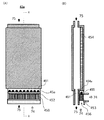
図3および図4に、本発明の航空機用空気調和システムで使用できる紫外線殺菌チャンバー43a及び紫外線光源45aの模式図を示す。これらは、加圧下および常圧下(大気圧下又は微負圧下)の何れでも使用可能である。図3及び図4において、導光板454がチャンバー43aの内部に配置され、UV-LED(好ましくはDUV-LED)451を有する紫外線光源45aがチャンバー43aの外部に配置されている。紫外線光源45aにおいては、必要に応じてパッケージ化されていてもよい複数のUV-LED(DUV-LED)451、451、…が、基板452上に1列に配列搭載されるとともに、紫外線透過性材料(例えばサファイアや石英等。)からなる蓋455で封止されている。基板452は放熱用フィン453を有するヒートシンクと一体化されている。放熱用フィン453は、紫外線発光ダイオード冷却用流体流路456内に露出しており、該流路456内を流通する紫外線発光ダイオード冷却用流体(図3では換気用新鮮空気74)に、UV-LED(DUV-LED)451で発生した熱を放熱する。紫外線光源45aの紫外線出射面は、導光板454の上流側端面454aに密着するように配置されている。導光板454の一方の主面(発光面)457には、光偏光素子457a、457a、…が設けられており、出射部として作用する。UV-LED(DUV-LED)451から出射された紫外線は上記端面454aから導光板454に入射し、導光板の光透過層(導光部458)を通って該発光面457から出射し、チャンバー43a内を流通する浄化再循環用空気75に照射される。
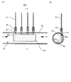
図5に、本発明の航空機用空気調和システムで使用できる他の紫外線殺菌チャンバー43bの模式図を示す。該紫外線殺菌チャンバー43bは金属製配管80をチャンバーとして利用したものであり、内部が加圧空間84となっている。金属製配管80の内部には紫外線出射部としての導光板454が配置されている。該導光板454は、その側面において、配管80に設けられた穴80aに固定された耐圧コネクタ83から配管内に延びた光ファイバと光学的に接続されている。耐圧コネクタ83から配管外に延びた光ファイバは、カップラー82において導光部の光ファイバ81の光出射ポートと光学的に接続されている。光ファイバ81は、もう一方の端部に存在する光入射ポート(図示せず)まで延びており、光源(図示せず)から出射された紫外線は該光入射ポートから取り入れられて光ファイバ81内を伝播し、光出射ポート及び耐圧コネクタ83を経由して導光板454から拡散光として出射される。導光板454から出射された紫外線が、紫外線反射性材料で構成される配管80の内壁面で反射を繰り返しながら進行し、配管80の内部を流通する浄化再循環用空気75に照射されることにより、殺菌が行われる。
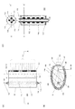
図6に、本発明の航空機用空気調和システムで使用できる更に他の紫外線殺菌チャンバー43c及び紫外線光源45cの模式図を示した。該紫外線殺菌チャンバー43cは、横長(浄化再循環用空気の流れる方向を長手方向とする)平箱状のチャンバー内において紫外線光源45cから出射された紫外線を浄化再循環用空気75に直接照射する構造となっている。紫外線光源45cは、チャンバーの上面とほぼ同一形状を有する矩形の基板452と、基板452aの表面に縦横夫々複数列に配列搭載された、(必要に応じてパッケージ化されていてもよい)複数のUV-LED(DUV-LED)451と、紫外線透過性材料(例えばサファイアや石英等。)からなり、UV-LED451を封止する蓋455と、を有する。基板452は放熱用フィン453を有するヒートシンクと一体化されている。放熱用フィン453は、紫外線発光ダイオード冷却用流体流路456内に露出しており、該流路456内を流通する紫外線発光ダイオード冷却用流体(図3では、換気用新鮮空気74。)によって、UV-LED(DUV-LED)451で発生した熱を放熱する。なお、紫外線殺菌チャンバー43cは、チャンバー内に紫外線光源45cそのものが配置されるため、常圧で使用することが好ましい。
最後に、図7に、本発明の航空機用空気調和システムで使用できる更に他の紫外線光源45dの模式図を示した。該紫外線光源45dは、特許文献9(特開2014-89898号公報)に開示されている紫外線殺菌装置100と同じものである。該紫外線光源45d(紫外線殺菌装置100)は、内面が長楕円反射ミラーからなる出射側反射ミラー120となっている出射側筐体125と、内面が長楕円反射ミラーからなる集光側反射ミラー123となっていると共に紫外線出射用開口部130が形成されている集光側筐体126と、紫外線出射用開口部130に配置されたコリメート光学系140とからなる本体(集光コリメート装置)150と;円筒状基体111、及び、円筒状基体111の側面に配置された複数のDUV-LED112を有し、該複数のDUV-LED112は、紫外線が基体111の中心軸114に対して放射状に出射されるように、各DUV-LED112の光軸115が前記基体111の中心軸114を通るように配置されている、棒状の紫外線発光モジュール110と、を有する。そして、前記出射側反射ミラーの焦点軸121上に前記紫外線発光モジュール110が配置され、該出射側反射ミラーの集光軸122(集光側反射ミラーの焦点軸124でもある)の近傍に紫外線出射用開口部130が設けられている。
さらに、前記円筒状基体111の内部には冷却媒体用流路113が形成されている。また、DUV-LED112が搭載された円筒状基体111は、紫外線透過性材料(例えば石英等。)から形成されるカバー116で覆われている。該カバー116は封止剤やパッキン、o-リング等のシール部材117を用いて気密又は水密に円筒状基体に装着され、その内部には窒素などの不活性ガス、乾燥空気などのガスが封入されている。上記円筒状基体111は、紫外線発光素子112を固定・保持するための支持体として機能するほか、ヒートシンクとしての機能も有する。すなわち、基体111の内部の冷却媒体用流路113に冷却媒体118(例えば換気用新鮮空気74、ラムエアー73等。)を流通することにより、紫外線発光素子から発せられる熱を放熱して、熱による紫外線発光素子の温度上昇を防止できるので、素子を安定に作動させること、及び、素子寿命を長くすることが可能である。
上記紫外線光源45dは、出光方向に向けて配置されたDUV-LEDから出射される光だけでなく、出光方向以外の方向に向けて配置されたDUV-LEDから出射される光も合わせて集光するので、高強度化された紫外線を帯状の並進光として出射することが可能となっている。したがって、導光板と組み合わせて使用する光源として好ましい。
10、10´・・・航空機用空気調和システム
20・・・キャビン
21・・・換気用空気供給口
22・・・キャビン空気排気口
23・・・ゾーン
24・・・圧力制御バルブ
30・・・抽気調和系流路
31、32・・・冷却用熱交換器
33・・・コンプレッサー
34・・・冷却タービン
40・・・再循環系流路
41・・・フィルター装置
42・・・電動コンプレッサー
43、43a、43b、43c・・・紫外線殺菌チャンバー
44・・・タービン
45、45a、45c、45d・・・紫外線光源
451・・・UV-LED(又はDUV-LED)
452・・・基板
453・・・放熱用フィン
454・・・導光板
455・・・紫外線透過性材料からなる蓋
456・・・紫外線発光ダイオード冷却用流体流路
457・・・出射部
458・・・導光部
46・・・ファン
50・・・混合器
51・・・換気用新鮮空気導入口
52・・・浄化再循環用空気導入口
53・・・換気用空気排出口
60・・・ゲートバルブ
61・・・温度調節バルブ
62・・・流量調節バルブ
63・・・ゲートバルブ
64・・・温度調節バルブ
70・・・第二の新鮮空気
71・・・第一の新鮮空気
72・・・キャビン内空気
73・・・ラムエアー
74・・・紫外線発光ダイオード冷却用流体
75・・・浄化再循環用空気
80・・・配管
81・・・光ファイバ
82・・・カップラー
83・・・耐圧コネクタ
84・・・加圧空間
100・・紫外線殺菌装置
110・・紫外線発光モジュール
111・・円筒状基体
112・・深紫外線発光素子(DUV-LED)
113・・冷却媒体用流路
114・・円筒状基体の中心軸
115・・深紫外線発光素子の光軸
116・・カバー
117・・シール部材
118・・冷却媒体
120・・長楕円反射ミラーからなる出射側反射ミラー
121・・出射側反射ミラーの焦点軸
122・・出射側反射ミラーの集光軸
123・・長楕円反射ミラーらなる集光側反射ミラー
124・・集光側反射ミラーの焦点軸
125・・出射側筐体
126・・集光側筐体
130・・紫外線出射用開口部
140・・コリメート光学系
150・・本体
20・・・キャビン
21・・・換気用空気供給口
22・・・キャビン空気排気口
23・・・ゾーン
24・・・圧力制御バルブ
30・・・抽気調和系流路
31、32・・・冷却用熱交換器
33・・・コンプレッサー
34・・・冷却タービン
40・・・再循環系流路
41・・・フィルター装置
42・・・電動コンプレッサー
43、43a、43b、43c・・・紫外線殺菌チャンバー
44・・・タービン
45、45a、45c、45d・・・紫外線光源
451・・・UV-LED(又はDUV-LED)
452・・・基板
453・・・放熱用フィン
454・・・導光板
455・・・紫外線透過性材料からなる蓋
456・・・紫外線発光ダイオード冷却用流体流路
457・・・出射部
458・・・導光部
46・・・ファン
50・・・混合器
51・・・換気用新鮮空気導入口
52・・・浄化再循環用空気導入口
53・・・換気用空気排出口
60・・・ゲートバルブ
61・・・温度調節バルブ
62・・・流量調節バルブ
63・・・ゲートバルブ
64・・・温度調節バルブ
70・・・第二の新鮮空気
71・・・第一の新鮮空気
72・・・キャビン内空気
73・・・ラムエアー
74・・・紫外線発光ダイオード冷却用流体
75・・・浄化再循環用空気
80・・・配管
81・・・光ファイバ
82・・・カップラー
83・・・耐圧コネクタ
84・・・加圧空間
100・・紫外線殺菌装置
110・・紫外線発光モジュール
111・・円筒状基体
112・・深紫外線発光素子(DUV-LED)
113・・冷却媒体用流路
114・・円筒状基体の中心軸
115・・深紫外線発光素子の光軸
116・・カバー
117・・シール部材
118・・冷却媒体
120・・長楕円反射ミラーからなる出射側反射ミラー
121・・出射側反射ミラーの焦点軸
122・・出射側反射ミラーの集光軸
123・・長楕円反射ミラーらなる集光側反射ミラー
124・・集光側反射ミラーの焦点軸
125・・出射側筐体
126・・集光側筐体
130・・紫外線出射用開口部
140・・コリメート光学系
150・・本体
Claims (9)
- (A)所定の圧力及び所定の温度を有する第一の新鮮空気を抽気すること、又は、
所定の圧力及び/又は所定の温度を有しない第二の新鮮空気を抽気し、抽気した第二の新鮮空気の圧力及び温度を所定の圧力及び所定の温度に調節することにより、
圧力及び温度が調節された換気用新鮮空気を得る、換気用新鮮空気調製工程、
(B)キャビン内に存在する空気をキャビン外に排気する排気工程、
(C)前記排気工程で排気された空気の一部を再循環用空気とし、フィルター及び/又は吸着材により該再循環用空気に含まれる汚染物質を除去又は低減して浄化再循環用空気を得る、浄化再循環用空気調製工程、
(D)前記換気用新鮮空気と前記浄化再循環用空気とを混合して換気用空気を得る、換気用空気調製工程、および
(E)前記換気用空気調製工程で得られた換気用空気を前記キャビン内に供給する、換気用空気供給工程
を含んでなる航空機用空気調和方法において、
(F)紫外線発光ダイオードから出射される紫外線を、前記換気用新鮮空気、前記再循環用空気、前記浄化再循環用空気、および前記キャビン内に供給される前の前記換気用空気よりなる群より選ばれる少なくとも1種に照射する、紫外線照射工程を更に含んでなる
ことを特徴とする航空機用空気調和方法。 - 前記(A)換気用新鮮空気調製工程は、冷却タービン及び/又は冷却用熱交換器を用いて前記第二の新鮮空気の温度を調節する工程を含み、
前記(F)紫外線照射工程において、
(1)前記冷却用熱交換器で使用する冷却用流体、
(2)前記冷却タービンを用いて冷却された空気、又は
(3)前記工程(A)で抽気した第一の新鮮空気、
によって前記紫外線発光ダイオードの温度制御を行うことを特徴とする、請求項1に記載の方法。 - 前記キャビンが複数のゾーンに分けられており、該複数のゾーンのそれぞれについて、
(B)排気工程、(F)前記紫外線を前記再循環用空気に照射する紫外線照射工程および(E)換気用空気供給工程
又は
(B)排気工程、(C)浄化再循環用空気調製工程、(F)前記紫外線を前記浄化再循環用空気に照射する紫外線照射工程および(E)換気用空気供給工程
を行うことを特徴とする請求項1又は2に記載の方法。 - 前記(F)紫外線照射工程を、キャビン内の気圧よりも高い気圧下で行うことを特徴とする請求項1乃至3の何れかに記載の方法。
- キャビン内に換気用空気を供給する換気用空気供給口と、
キャビン内の空気を排出するキャビン空気排気口と、
所定の圧力及び/又は所定の温度を有しない新鮮空気を抽気するための抽気口と、
空気圧送手段及びフィルター装置を流路内に含み、前記キャビン空気排気口から排出された空気の一部を前記フィルター装置により浄化して浄化再循環用空気を得る再循環系流路と、
コンプレッサー、冷却タービン及び冷却用熱交換器よりなる群より選ばれる少なくとも1種を有する空気調和装置を流路内に含み、前記抽気口から抽気された新鮮空気の圧力及び温度を調節して換気用新鮮空気を得る抽気調和系流路と、
前記再循環系流路と接続する浄化再循環用空気導入口と、前記抽気調和系流路と接続する換気用新鮮空気導入口と、前記換気用空気供給口と接続する換気用空気排出口とを有し、その内部で前記浄化再循環用空気と前記換気用新鮮空気とを混合して換気用空気を得る混合容器と、
を含んでなる航空機用空気調和システムにおいて、
紫外線発光ダイオードを有する紫外線照射装置であって、前記紫外線発光ダイオードから出射される紫外線を、前記再循環系流路内を流通する空気に照射する紫外線照射装置を更に含むことを特徴とする航空機用空気調和システム。 - 前記紫外線発光ダイオードから発生する熱を放熱する放熱用ヒートシンク又は放熱器と、紫外線発光ダイオード冷却用流体流路と、を含む紫外線発光ダイオード冷却手段を有し、
前記紫外線発光ダイオード冷却用流体流路は、前記冷却用熱交換器で使用される冷却用流体の流路又は前記抽気調和系流路と接続し、且つ、前記冷却用熱交換器で使用される冷却用流体の一部又は前記換気用新鮮空気の一部からなる紫外線発光ダイオード冷却用流体が流通し、
前記紫外線発光ダイオード冷却手段は、前記紫外線発光ダイオード冷却用流体と、放熱用ヒートシンク又は放熱器とを、直接又は間接的に接触させることによって前記紫外線発光ダイオードの冷却を行うことを特徴とする、請求項5に記載の航空機用空気調和システム。 - 前記再循環系流路は、
前記空気圧送手段としてのコンプレッサー、
該コンプレッサーより下流側に配置される圧力調整流出弁またはタービン、及び、
前記コンプレッサーと前記圧力調整流出弁またはタービンとの間に形成される加圧空間
を有し、
前記紫外線発光ダイオードから出射される紫外線を、前記加圧空間内を流通する空気に照射することを特徴とする、請求項5又は6に記載の航空機用空気調和システム。 - 前記紫外線照射装置が、
紫外線発光ダイオードを有し、前記加圧空間の外部に配置された光源と、
前記加圧空間内に配置された紫外線出射用光学部材と、
を有し、
前記紫外線発光ダイオードから発せられた紫外線を前記紫外線出射用光学部材から出射することにより、前記加圧空間内を流通する空気に紫外線を照射することを特徴とする、請求項7に記載の航空機用空気調和システム。 - 請求項5乃至8の何れかに記載の航空機用空気調和システムを有する航空機。
Priority Applications (1)
| Application Number | Priority Date | Filing Date | Title |
|---|---|---|---|
| US15/748,935 US20190009912A1 (en) | 2015-08-31 | 2016-08-29 | Method for air conditioning of aircraft, and air conditioning system therefor |
Applications Claiming Priority (2)
| Application Number | Priority Date | Filing Date | Title |
|---|---|---|---|
| JP2015170374A JP6124962B2 (ja) | 2015-08-31 | 2015-08-31 | 航空機用空気調和方法及び該方法に用いる空気調和システム |
| JP2015-170374 | 2015-08-31 |
Publications (1)
| Publication Number | Publication Date |
|---|---|
| WO2017038780A1 true WO2017038780A1 (ja) | 2017-03-09 |
Family
ID=58187615
Family Applications (1)
| Application Number | Title | Priority Date | Filing Date |
|---|---|---|---|
| PCT/JP2016/075235 Ceased WO2017038780A1 (ja) | 2015-08-31 | 2016-08-29 | 航空機用空気調和方法及び該方法に用いる空気調和システム |
Country Status (3)
| Country | Link |
|---|---|
| US (1) | US20190009912A1 (ja) |
| JP (1) | JP6124962B2 (ja) |
| WO (1) | WO2017038780A1 (ja) |
Cited By (2)
| Publication number | Priority date | Publication date | Assignee | Title |
|---|---|---|---|---|
| JP6990335B1 (ja) | 2020-08-18 | 2022-01-12 | 広東国志激光技術有限公司 | セントラル空調用の殺ウイルス及び滅菌装置 |
| EP3944869B1 (en) * | 2020-07-27 | 2025-04-02 | Goodrich Corporation | Duct assemblies for air management systems and methods of manufacture |
Families Citing this family (31)
| Publication number | Priority date | Publication date | Assignee | Title |
|---|---|---|---|---|
| US10703491B2 (en) | 2017-11-28 | 2020-07-07 | Hamilton Sunstrand Corporation | Aircraft cabin air monitor |
| US11465770B2 (en) * | 2019-03-01 | 2022-10-11 | Hamilton Sundstrand Corporation | Air cycle machine connected to engine gearbox |
| CN110748991B (zh) * | 2019-10-22 | 2021-06-29 | 济宁市丰泰医疗器械有限公司 | 一种用于智慧医疗的杀菌能力强的医用空气净化器 |
| EP3845455B1 (en) * | 2019-12-31 | 2023-04-19 | Hamilton Sundstrand Corporation | Aircraft environmental control system |
| CN111268141B (zh) | 2020-02-28 | 2021-02-19 | 南京航空航天大学 | 飞机高温消毒灭菌空调系统及消毒灭菌方法 |
| EP3882153B1 (en) * | 2020-03-17 | 2025-10-29 | Hamilton Sundstrand Corporation | Fresh air ecs |
| EP3904211B1 (en) * | 2020-04-30 | 2025-01-08 | Hamilton Sundstrand Corporation | Integration of uv light into aircraft air management systems |
| US11511013B2 (en) | 2020-05-08 | 2022-11-29 | Madhavan Pisharodi | Air purification and disinfection apparatus and methods of use |
| WO2021225614A1 (en) * | 2020-05-08 | 2021-11-11 | Madhavan Pisharodi | Systems, apparatus and methods for purifying air |
| US12042764B2 (en) * | 2020-05-11 | 2024-07-23 | Hamilton Sundstrand Corporation | Aircraft air management systems for deactivating contaminants |
| US11904267B2 (en) * | 2020-06-19 | 2024-02-20 | The Boeing Company | Apparatus and method for irradiating air in an air circulation system of a vehicle |
| US12097310B2 (en) * | 2020-06-19 | 2024-09-24 | The Boeing Company | Apparatus and method for irradiating air in an air circulation system of a vehicle |
| WO2022011472A1 (en) * | 2020-07-17 | 2022-01-20 | 12180235 Canada Ltd. | Apparatus for reflecting an incident ray of electromagnetic radiation |
| KR102901327B1 (ko) * | 2020-08-21 | 2025-12-16 | 한화오션 주식회사 | 감염병 방지 기능을 갖는 에어컨 시스템 및 동 시스템을 구비한 선박 |
| KR102407088B1 (ko) * | 2020-08-28 | 2022-06-13 | 한국에너지기술연구원 | 압축기를 이용한 청정 음압병실 시스템 |
| US11236915B1 (en) * | 2020-09-10 | 2022-02-01 | RHC Ventures, LLC | Systems and methods for batch processing air taken from a populated environment to destroy pathogens and then reintroduce the air into the populated environment |
| AT524270B1 (de) * | 2020-09-17 | 2022-09-15 | Facc Ag | Verfahren zur Behandlung von Abluft einer Flugzeugkabine eines Flugzeugs |
| US12201932B2 (en) * | 2020-10-16 | 2025-01-21 | Adam R. Skelton | Air purification system for passenger transport cabin |
| PL436649A1 (pl) * | 2021-01-12 | 2022-07-18 | Fret Robert | Instalacja ograniczająca wzajemne zakażenie wirusologiczne osób przebywających w pomieszczeniu - zwłaszcza w pomieszczeniu użytku publicznego oraz urządzenie filtracyjne uzdatniające powietrze do oddychania dla takiej instalacji |
| US20220296742A1 (en) * | 2021-03-18 | 2022-09-22 | GM Global Technology Operations LLC | Antibacterial interior components and methods for use thereof |
| US11255555B1 (en) * | 2021-05-10 | 2022-02-22 | Olympia Lighting, Inc. | Ultraviolet disinfection device and uses thereof |
| US12564627B2 (en) | 2021-08-16 | 2026-03-03 | Perumala Holdings, LLC | System for producing and delivering contactless veterinary passive immunization |
| US12298037B2 (en) | 2021-08-16 | 2025-05-13 | Perumala Holdings, LLC | System for delivery of inactivated pathogens for contactless passive immunization |
| US12194206B2 (en) | 2021-08-16 | 2025-01-14 | Perumala Holdings, LLC | Expandable system for purification and disinfection of air |
| US11951164B2 (en) | 2021-08-16 | 2024-04-09 | Perumala Holdings, LLC | Systems and methods for the preparation of vaccines utilizing predictably inactivated pathogens |
| CN113911370A (zh) * | 2021-09-03 | 2022-01-11 | 中国电子科技集团公司第十一研究所 | 一种环控组件 |
| US20230406515A1 (en) * | 2022-05-17 | 2023-12-21 | Hamilton Sundstrand Corporation | Hydrogen-cooled environmental control system |
| US12588134B2 (en) * | 2022-06-02 | 2026-03-24 | Uv-Clear, Inc | Air directing scoop for heat sink and UV-C apparatus |
| US20260021218A1 (en) * | 2022-07-22 | 2026-01-22 | Ams-Osram International Gmbh | Optoelectronic device |
| US12391388B2 (en) * | 2022-12-05 | 2025-08-19 | Hamilton Sundstrand Corporation | Recirculation air motor driven ACM |
| US12465537B2 (en) | 2023-06-02 | 2025-11-11 | Perumala Holdings, LLC | Self-cleaning air flow for air-conditioned facilities |
Citations (4)
| Publication number | Priority date | Publication date | Assignee | Title |
|---|---|---|---|---|
| US20070053188A1 (en) * | 2005-09-06 | 2007-03-08 | Luminator Holding, L.P. | LED ultraviolet air sanitizer light fixture |
| JP2009526690A (ja) * | 2006-02-16 | 2009-07-23 | エアバス ドイチェランド ゲゼルシャフト ミット ベシュレンクテル ハフツング | 航空機の与圧客室における空気品質を改善するシステム |
| US20140017135A1 (en) * | 2012-07-16 | 2014-01-16 | Mag Aerospace Industries, Inc. | Systems and Methods for Disinfecting Air On Board A Passenger Transport Vehicle |
| JP2014089898A (ja) * | 2012-10-30 | 2014-05-15 | Tokuyama Corp | 紫外線発光モジュール及び紫外線照射装置 |
Family Cites Families (4)
| Publication number | Priority date | Publication date | Assignee | Title |
|---|---|---|---|---|
| US8336821B2 (en) * | 2005-03-31 | 2012-12-25 | The Boeing Company | Systems and methods for cargo compartment air conditioning using recirculated air |
| EP1857363A1 (fr) * | 2006-05-19 | 2007-11-21 | Lebrun Nimy | Dispositif de régulation de température |
| FR2975969B1 (fr) * | 2011-05-30 | 2013-06-07 | Turbomeca | Systeme de conditionnement d'air d'un compartiment pour passagers d'un aeronef |
| US8936671B2 (en) * | 2013-02-22 | 2015-01-20 | The Boeing Company | Aircraft cabin air entrainment filtration with condensation drain |
-
2015
- 2015-08-31 JP JP2015170374A patent/JP6124962B2/ja active Active
-
2016
- 2016-08-29 WO PCT/JP2016/075235 patent/WO2017038780A1/ja not_active Ceased
- 2016-08-29 US US15/748,935 patent/US20190009912A1/en not_active Abandoned
Patent Citations (4)
| Publication number | Priority date | Publication date | Assignee | Title |
|---|---|---|---|---|
| US20070053188A1 (en) * | 2005-09-06 | 2007-03-08 | Luminator Holding, L.P. | LED ultraviolet air sanitizer light fixture |
| JP2009526690A (ja) * | 2006-02-16 | 2009-07-23 | エアバス ドイチェランド ゲゼルシャフト ミット ベシュレンクテル ハフツング | 航空機の与圧客室における空気品質を改善するシステム |
| US20140017135A1 (en) * | 2012-07-16 | 2014-01-16 | Mag Aerospace Industries, Inc. | Systems and Methods for Disinfecting Air On Board A Passenger Transport Vehicle |
| JP2014089898A (ja) * | 2012-10-30 | 2014-05-15 | Tokuyama Corp | 紫外線発光モジュール及び紫外線照射装置 |
Cited By (3)
| Publication number | Priority date | Publication date | Assignee | Title |
|---|---|---|---|---|
| EP3944869B1 (en) * | 2020-07-27 | 2025-04-02 | Goodrich Corporation | Duct assemblies for air management systems and methods of manufacture |
| JP6990335B1 (ja) | 2020-08-18 | 2022-01-12 | 広東国志激光技術有限公司 | セントラル空調用の殺ウイルス及び滅菌装置 |
| JP2022034539A (ja) * | 2020-08-18 | 2022-03-03 | 広東国志激光技術有限公司 | セントラル空調用の殺ウイルス及び滅菌装置 |
Also Published As
| Publication number | Publication date |
|---|---|
| JP2017047715A (ja) | 2017-03-09 |
| JP6124962B2 (ja) | 2017-05-10 |
| US20190009912A1 (en) | 2019-01-10 |
Similar Documents
| Publication | Publication Date | Title |
|---|---|---|
| JP6124962B2 (ja) | 航空機用空気調和方法及び該方法に用いる空気調和システム | |
| JP6282678B2 (ja) | 空気調和方法及び空気調和システム | |
| JP2017074943A (ja) | 航空機用空気調和方法及び該方法に用いる空気調和システム | |
| JP2018021752A (ja) | 空気調和方法及び空気調和システム | |
| JP3476460B2 (ja) | ヘリコプター用一体型環境制御システム | |
| CN105268311A (zh) | 具有以占空比操作的紫外led的光催化剂空气净化系统 | |
| TW200422566A (en) | Ultraviolet-light vehicle air cleaning system | |
| CN207527707U (zh) | 具有杀菌功能的空调器 | |
| US10082285B2 (en) | Exterior aircraft light unit | |
| JP7737243B2 (ja) | 空気清浄システム | |
| US11413573B2 (en) | Air purifying system | |
| KR20180018328A (ko) | 촉매 장치 및 이를 포함하는 차량용 공조장치 | |
| US20110146816A1 (en) | Device for disinfecting a motor vehicle air-conditioning system | |
| US20220265890A1 (en) | Fluid processing | |
| US20240219049A1 (en) | Air sterilizer and air conditioning apparatus using the same | |
| EP3904211B1 (en) | Integration of uv light into aircraft air management systems | |
| CN113813702B (zh) | 对交通工具的空气循环系统的空气进行辐照的设备和方法 | |
| US12059941B2 (en) | Ventilation seat of vehicle | |
| CN113183725B (zh) | 一种汽车及其空调消杀装置 | |
| KR20160035828A (ko) | 광촉매 장치 | |
| JP2019031163A (ja) | 熱交換器の殺菌・洗浄方法及び熱交換器の殺菌・洗浄システム | |
| CN114191932B (zh) | 空气杀菌系统 | |
| CN113970155A (zh) | 空气净化系统 | |
| US12337973B2 (en) | Methods, systems, and apparatuses for reducing ozone concentration and reducing VOC concentration in aircraft cabin environment recirculated airflow | |
| JP2010012378A (ja) | 除湿装置 |
Legal Events
| Date | Code | Title | Description |
|---|---|---|---|
| 121 | Ep: the epo has been informed by wipo that ep was designated in this application |
Ref document number: 16841812 Country of ref document: EP Kind code of ref document: A1 |
|
| NENP | Non-entry into the national phase |
Ref country code: DE |
|
| 122 | Ep: pct application non-entry in european phase |
Ref document number: 16841812 Country of ref document: EP Kind code of ref document: A1 |