WO2017033643A1 - Booster device for driving injector - Google Patents
Booster device for driving injector Download PDFInfo
- Publication number
- WO2017033643A1 WO2017033643A1 PCT/JP2016/071659 JP2016071659W WO2017033643A1 WO 2017033643 A1 WO2017033643 A1 WO 2017033643A1 JP 2016071659 W JP2016071659 W JP 2016071659W WO 2017033643 A1 WO2017033643 A1 WO 2017033643A1
- Authority
- WO
- WIPO (PCT)
- Prior art keywords
- injector
- booster
- driving
- boost
- voltage
- Prior art date
Links
Images


Classifications
-
- F—MECHANICAL ENGINEERING; LIGHTING; HEATING; WEAPONS; BLASTING
- F02—COMBUSTION ENGINES; HOT-GAS OR COMBUSTION-PRODUCT ENGINE PLANTS
- F02D—CONTROLLING COMBUSTION ENGINES
- F02D41/00—Electrical control of supply of combustible mixture or its constituents
- F02D41/20—Output circuits, e.g. for controlling currents in command coils
-
- F—MECHANICAL ENGINEERING; LIGHTING; HEATING; WEAPONS; BLASTING
- F02—COMBUSTION ENGINES; HOT-GAS OR COMBUSTION-PRODUCT ENGINE PLANTS
- F02D—CONTROLLING COMBUSTION ENGINES
- F02D41/00—Electrical control of supply of combustible mixture or its constituents
- F02D41/30—Controlling fuel injection
- F02D41/38—Controlling fuel injection of the high pressure type
- F02D41/40—Controlling fuel injection of the high pressure type with means for controlling injection timing or duration
- F02D41/402—Multiple injections
-
- F—MECHANICAL ENGINEERING; LIGHTING; HEATING; WEAPONS; BLASTING
- F02—COMBUSTION ENGINES; HOT-GAS OR COMBUSTION-PRODUCT ENGINE PLANTS
- F02M—SUPPLYING COMBUSTION ENGINES IN GENERAL WITH COMBUSTIBLE MIXTURES OR CONSTITUENTS THEREOF
- F02M51/00—Fuel-injection apparatus characterised by being operated electrically
- F02M51/06—Injectors peculiar thereto with means directly operating the valve needle
-
- F—MECHANICAL ENGINEERING; LIGHTING; HEATING; WEAPONS; BLASTING
- F02—COMBUSTION ENGINES; HOT-GAS OR COMBUSTION-PRODUCT ENGINE PLANTS
- F02M—SUPPLYING COMBUSTION ENGINES IN GENERAL WITH COMBUSTIBLE MIXTURES OR CONSTITUENTS THEREOF
- F02M61/00—Fuel-injectors not provided for in groups F02M39/00 - F02M57/00 or F02M67/00
- F02M61/04—Fuel-injectors not provided for in groups F02M39/00 - F02M57/00 or F02M67/00 having valves, e.g. having a plurality of valves in series
- F02M61/10—Other injectors with elongated valve bodies, i.e. of needle-valve type
-
- F—MECHANICAL ENGINEERING; LIGHTING; HEATING; WEAPONS; BLASTING
- F02—COMBUSTION ENGINES; HOT-GAS OR COMBUSTION-PRODUCT ENGINE PLANTS
- F02D—CONTROLLING COMBUSTION ENGINES
- F02D41/00—Electrical control of supply of combustible mixture or its constituents
- F02D41/20—Output circuits, e.g. for controlling currents in command coils
- F02D2041/2003—Output circuits, e.g. for controlling currents in command coils using means for creating a boost voltage, i.e. generation or use of a voltage higher than the battery voltage, e.g. to speed up injector opening
- F02D2041/2006—Output circuits, e.g. for controlling currents in command coils using means for creating a boost voltage, i.e. generation or use of a voltage higher than the battery voltage, e.g. to speed up injector opening by using a boost capacitor
-
- F—MECHANICAL ENGINEERING; LIGHTING; HEATING; WEAPONS; BLASTING
- F02—COMBUSTION ENGINES; HOT-GAS OR COMBUSTION-PRODUCT ENGINE PLANTS
- F02D—CONTROLLING COMBUSTION ENGINES
- F02D41/00—Electrical control of supply of combustible mixture or its constituents
- F02D41/20—Output circuits, e.g. for controlling currents in command coils
- F02D2041/2003—Output circuits, e.g. for controlling currents in command coils using means for creating a boost voltage, i.e. generation or use of a voltage higher than the battery voltage, e.g. to speed up injector opening
- F02D2041/2013—Output circuits, e.g. for controlling currents in command coils using means for creating a boost voltage, i.e. generation or use of a voltage higher than the battery voltage, e.g. to speed up injector opening by using a boost voltage source
-
- F—MECHANICAL ENGINEERING; LIGHTING; HEATING; WEAPONS; BLASTING
- F02—COMBUSTION ENGINES; HOT-GAS OR COMBUSTION-PRODUCT ENGINE PLANTS
- F02D—CONTROLLING COMBUSTION ENGINES
- F02D41/00—Electrical control of supply of combustible mixture or its constituents
- F02D41/20—Output circuits, e.g. for controlling currents in command coils
- F02D2041/202—Output circuits, e.g. for controlling currents in command coils characterised by the control of the circuit
- F02D2041/2058—Output circuits, e.g. for controlling currents in command coils characterised by the control of the circuit using information of the actual current value
-
- F—MECHANICAL ENGINEERING; LIGHTING; HEATING; WEAPONS; BLASTING
- F02—COMBUSTION ENGINES; HOT-GAS OR COMBUSTION-PRODUCT ENGINE PLANTS
- F02D—CONTROLLING COMBUSTION ENGINES
- F02D41/00—Electrical control of supply of combustible mixture or its constituents
- F02D41/20—Output circuits, e.g. for controlling currents in command coils
- F02D2041/2068—Output circuits, e.g. for controlling currents in command coils characterised by the circuit design or special circuit elements
-
- F—MECHANICAL ENGINEERING; LIGHTING; HEATING; WEAPONS; BLASTING
- F02—COMBUSTION ENGINES; HOT-GAS OR COMBUSTION-PRODUCT ENGINE PLANTS
- F02D—CONTROLLING COMBUSTION ENGINES
- F02D41/00—Electrical control of supply of combustible mixture or its constituents
- F02D41/30—Controlling fuel injection
- F02D41/38—Controlling fuel injection of the high pressure type
- F02D2041/389—Controlling fuel injection of the high pressure type for injecting directly into the cylinder
-
- F—MECHANICAL ENGINEERING; LIGHTING; HEATING; WEAPONS; BLASTING
- F02—COMBUSTION ENGINES; HOT-GAS OR COMBUSTION-PRODUCT ENGINE PLANTS
- F02D—CONTROLLING COMBUSTION ENGINES
- F02D41/00—Electrical control of supply of combustible mixture or its constituents
- F02D41/02—Circuit arrangements for generating control signals
- F02D41/04—Introducing corrections for particular operating conditions
- F02D41/08—Introducing corrections for particular operating conditions for idling
-
- Y—GENERAL TAGGING OF NEW TECHNOLOGICAL DEVELOPMENTS; GENERAL TAGGING OF CROSS-SECTIONAL TECHNOLOGIES SPANNING OVER SEVERAL SECTIONS OF THE IPC; TECHNICAL SUBJECTS COVERED BY FORMER USPC CROSS-REFERENCE ART COLLECTIONS [XRACs] AND DIGESTS
- Y02—TECHNOLOGIES OR APPLICATIONS FOR MITIGATION OR ADAPTATION AGAINST CLIMATE CHANGE
- Y02T—CLIMATE CHANGE MITIGATION TECHNOLOGIES RELATED TO TRANSPORTATION
- Y02T10/00—Road transport of goods or passengers
- Y02T10/10—Internal combustion engine [ICE] based vehicles
- Y02T10/40—Engine management systems
Definitions
- the present invention relates to a booster for driving an injector.
- Patent Document 1 discloses a control that has a function of detecting a current of a solenoid used for boosting in a boosting circuit in fuel injection valve opening control, and changes a target voltage in accordance with the current value. Moreover, the apparatus of patent document 1 controls the duty ratio of step-up FET so that it may become the voltage which should be applied to a solenoid at the time of the next fuel injection with the detected electric current.
- Patent Document 2 discloses control in which a charging current is increased stepwise by determining that a booster circuit in a fuel injection device has a temperature detection portion and a plurality of temperature threshold values and is lower than a predetermined temperature threshold value. Yes. Moreover, the apparatus of patent document 2 carries out increase control of charging current, when it determines with the present voltage being low compared with a predetermined voltage.
- Patent Document 3 discloses control for adjusting a target voltage for boosting using at least one of an ECU temperature, an outside air temperature, a vehicle speed, and a coolant temperature in a fuel injection device that performs multistage injection.
- JP 2005-163625 A Japanese Patent Laid-Open No. 2014-214693 JP 2014-159772 A
- the continuous injection timing of the fuel injection device is not intended, and the boost voltage value for the next and subsequent times is determined based only on the current value, and the boost FET is controlled.
- the boost voltage value for the next and subsequent times is determined based only on the current value, and the boost FET is controlled.
- the boost voltage value for the next and subsequent times is determined based only on the current value, and the boost FET is controlled.
- An object of the present invention is to provide a booster for driving an injector capable of suppressing a shortage of boosted voltage applied to an injector even when a fuel injection interval is short.
- the present invention provides a coil, a switching element connected in series to the coil, for turning on / off the coil, a capacitor for applying a voltage to an injector, the coil, and the coil
- a determination period indicating a period corresponding to an injection interval of the injector and an anode connected to a connection point of a switching element and a cathode connected to the capacitor is equal to or less than a first threshold value, charging of the capacitor
- a control circuit for controlling on / off of the switching element so as to increase the speed.
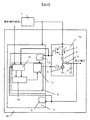
- FIG. 1 is a configuration diagram of an injector driving booster according to a first embodiment of the present invention.
- FIG. It is a figure which shows the waveform of the pressure
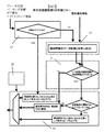
- FIG. 5 is a diagram showing a control flow of a booster circuit driving unit shown in FIG. 4.
- FIG. 7 is a diagram illustrating a control flow of a booster circuit driving unit illustrated in FIG. 6.
- the boost driver 1 (switching element) turns on / off the energization of the boost coil 4.
- the boost driver 1 is, for example, a MOSFET (Metal
- the current at this time is detected as a voltage across the shunt resistor 3 by the current monitor circuit 12 included in the booster circuit drive unit 5 inside the driver IC 9.
- the boost gate control circuit 11 turns off the boost driver 1.
- the current I flows through the boost diode 6 due to the back electromotive force of the boost coil 4.
- the boost capacitor 7 plays a role of temporarily storing the current passed through the boost diode 6.
- the boost capacitor 7 applies a boost voltage to the fuel injection valve via a driver (not shown) that drives the fuel injection valve (injector).
- the step-up diode 6 has an anode connected to a connection point between the step-up coil 4 and the step-up driver 1 (switching element) and a cathode connected to the step-up capacitor 7.
- the booster driver 1 is turned on again, and the current value increases. By repeating this, a current continues to flow through the boost diode 6 and the current is stored in the boost capacitor 7 to generate a boost voltage.
- the booster voltage monitor circuit 8 is provided in the driver IC 9 to boost the voltage when the voltage is low, and monitor the boosted voltage to stop the boosting when the voltage reaches a predetermined value.
- Fig. 2 shows the waveform of the boosting operation.
- the gate signal for turning on the boost driver 1 is Vg. When this is turned on, the drain voltage Vd of the boost driver 1 is lowered to around 0 V, and the current I is increased. When the current I reaches the set Max current with respect to the target current value, the gate signal Vg of the boost driver 1 is turned OFF. At that time, Vd reaches the boost voltage, and the current I flows to the boost diode 6 side and is stored in the boost capacitor 7, but the current value itself decreases with time.
- the booster driver 1 When the set Min current is reached, the booster driver 1 is turned on again, so that the operation of FIG. 2 is performed by repeating this operation.
- the operation of FIG. 2 is performed until the boosted voltage reaches the set value.
- the hatched portion in the figure is the current that actually flows through the boost diode 6 and is the current used for boosting.
- a waveform like the boosted voltage in FIG. 2 is obtained.
- Vg is OFF, a current flows through the boost capacitor 7, so that the boost voltage rises.
- Vg is ON, no current flows into the boost capacitor 7, so it does not increase (slightly decreases because natural discharge is performed).
- boosting by Vg switching is performed until the boosted voltage reaches a predetermined value.
- the boosted voltage for performing fuel injection comes to a close injection timing such that the next fuel injection is performed before reaching the target voltage, it occurs due to insufficient boosted voltage.
- the purpose is to eliminate the difference in fuel injection characteristics.
- FIG. 3 is a diagram for explaining the first embodiment of the present invention.
- FIG. 3 shows a boosting switching element (boost driver) when the fuel injection is performed when the boosted voltage for performing the fuel injection comes close to the next fuel injection before reaching the target voltage.
- boost driver boosting switching element
- the ON and OFF Duty and frequency of 1) are varied to increase the average value of the boost current to increase the boost speed (charging speed).
- the boosting speed is determined by the average current value of the booster circuit 51, it can be controlled by controlling the ON / OFF time of the boosting switching element, that is, the duty and cycle of the boosting switching element. For example, when trying to increase the boosting speed, the average current value at the time of boosting is increased by changing the duty and cycle of the boosting switching element, thereby increasing the energy for boosting and increasing the boosting speed. .
- the boost gate control circuit 11 determines that the boost driver 1 ( ON / OFF of the switching element) is controlled. That is, when the determination period is equal to or shorter than the first threshold value Tha, the boost gate control circuit 11 controls the on / off of the boost driver 1 so as to increase at least one of the duty ratio and the switching frequency of the boost driver 1. To do.
- the counter is configured so that the voltage of the boost capacitor 7 is applied to the injector for the second injection from the timing when the energization current of the injector reaches a peak current indicating a predetermined current value for the first injection (fuel). The period until the injection signal pulse rises) is measured as the determination period.
- the energization current of the injector is measured by, for example, a current sensor (not shown).
- the counter may measure the period from the timing when the voltage of the boost capacitor 7 is applied to the injector to the timing when the energization current of the injector reaches the peak current indicating a predetermined current value as the determination period.
- the determination period at this time is a period during which the voltage of the boost capacitor 7 is applied to the injector.
- the shortage of the boost voltage applied to the injector can be suppressed even when the fuel injection interval is short.
- a constant boost voltage is set. Can be supplied to the fuel injection valve. Therefore, the rise time of the current for opening the valve can be made constant, the injection amount accuracy can be maintained, and the exhaust deterioration can be suppressed.
- FIG. 4 is a circuit configuration of the second embodiment of the present invention
- FIG. 5 is a control flow of the booster circuit drive unit 5 for realizing FIG.
- a fuel injection information recording circuit 15 and a determination circuit 16 are provided in the circuit configuration of FIG.
- the fuel injection information recording circuit 15 is input with at least one of the rotation signal of the internal combustion engine, the output of the crank angle sensor of the internal combustion engine, the setting information of the divided injection interval, or the setting information of the divided injection number, which is the fuel injection information. Is done.
- the fuel injection information recording circuit 15 has a built-in counter for measuring the interval of the input fuel injection signal and a memory for recording the above-mentioned fuel injection information.
- the current and past fuel injection interval information is stored in the determination circuit 16. Output.
- the judgment circuit 16 compares the current and past fuel injection interval information input from the fuel injection information recording circuit 15 and compares whether the comparison result is smaller or larger than a predetermined judgment time. Output to the circuit 11.
- the boosting gate control circuit 11 varies the ON / OFF duty and frequency of the boosting switching element, and calculates the average value of the boosting current. Increase the pressure to speed up the pressure.
- n-1 is past injection information. Since feedback is performed for the current n-th injection using the injection information for the first time, it is not possible to control the boosting speed-up for the n-1th injection. However, when the setting information of the divided injection interval can be obtained in advance, the boosting speed can be varied in real time.
- the injector performs divided injection in which fuel is injected a plurality of times during one combustion cycle of a direct injection internal combustion engine that injects fuel directly into the cylinder, and the boost gate control circuit 11 is in one combustion cycle.
- the determination period may be predicted.
- FIG. 6 is a circuit configuration of the third embodiment of the present invention
- FIG. 7 is a control flow of the booster circuit drive unit 5 for realizing FIG.
- an idle determination circuit 17 and a booster circuit temperature detection circuit 18 are provided in the circuit configuration of FIG.
- the booster circuit temperature detection circuit 18 measures the temperature of the injector drive booster 10.
- the idle determination circuit 17 is input with at least one of brake information, parking information, gear information, and idle stop information as vehicle travel information.
- the idle determination circuit 17 determines (determines) based on the input information whether the engine (internal combustion engine) is in an idle state where the engine speed is maintained at a constant low speed. When it is determined that the vehicle is in an idle state, the idle determination circuit 17 sends a signal indicating that the vehicle is in an idle state directly to the boost gate control circuit 11.
- the boosting gate circuit 11 Upon receiving the idle state from the idle determination circuit 17, the boosting gate circuit 11 changes the ON / OFF duty of the boosting switching element and the frequency, and decreases the average value of the boosting current to reduce the boosting speed. Control.
- the boost gate control circuit 11 reduces at least one of the duty ratio and the switching frequency of the boost driver 1 (switching element) when it is determined that the engine (internal combustion engine) is in an idle state.
- the on / off of the boost driver 1 is controlled.
- the idle determination circuit 17 when the idle determination circuit 17 does not determine the idle state, the idle determination circuit 17 sends a signal indicating that the fuel injection information recording circuit 15 is not in the idle state.
- the fuel injection information recording circuit 15 that is determined not to be in the idle state outputs the current and past fuel injection interval information to the determination circuit 16 as in the second embodiment.
- the judgment circuit 16 compares the current and past fuel injection interval information input from the fuel injection information recording circuit 15 and compares whether the comparison result is smaller or larger than a predetermined judgment time. Output to the circuit 11.
- the boosting gate control circuit 11 when it is necessary to increase the boosting speed, the boosting gate control circuit 11 varies the ON and OFF duty and frequency of the boosting switching element, and calculates the average value of the boosting current. Increase the pressure boosting speed and control the acceleration.
- the temperature information from the booster circuit temperature detection circuit 18 is received, and when the temperature information is higher than the threshold value, it is determined that the injector driving booster 10 is overworked, and the boost gate control circuit 11 Stops the acceleration of the boosting speed.
- the boosting gate control circuit 11 has a determination period indicating a period corresponding to the injection interval of the injector being equal to or lower than the first threshold value Tha, and the temperature of the injector driving booster 10 is equal to or lower than the second threshold value Thb. In this case, on / off of the boost driver 1 is controlled so as to increase at least one of the duty ratio and the switching frequency of the boost driver 1 (switching element).
- the injector driving booster 10 includes the idle determination circuit 17 and the booster circuit temperature detection circuit 18 (temperature sensor), but may include only one of them.
- FIG. 8 is a circuit configuration of the fourth embodiment of the present invention
- FIG. 9 is a diagram showing a waveform of the boosting operation of the injector driving booster shown in FIG.
- the circuit configuration of FIG. 8 is a configuration in which the current value obtained by the current monitor circuit 12 and the boosted voltage value obtained by the boosted voltage monitor circuit 8 are fed back to the fuel injection information recording circuit 15 in the circuit configuration of FIG. .
- the boost voltage monitor circuit 8 (voltage sensor) measures the voltage of the boost capacitor 7.
- the point where the current value is maximum in the current information is set as the fuel injection current peak, and the boost voltage monitor circuit 8 Using the obtained boost voltage value, the time A until the fuel injection current peak when the fuel injection signal is input and the fuel injection current peak comes before the boost voltage value reaches the target voltage, and the boost voltage value is the target It has a counter that measures time B when the voltage value is reached, and a memory that stores time A and time B.
- the counter is configured so that the voltage of the boosting capacitor 7 reaches the peak current after the voltage of the boosting capacitor 7 reaches the target voltage and after the voltage of the boosting capacitor 7 is applied to the injector.
- a period B until the voltage reaches the target voltage again is measured as the first threshold value Tha.
- a plurality of preset values for the boosting speed are prepared for the preset switching ON / OFF duty and frequency of the boosting switching element.
- the time A and the time B measured by the counter are compared.
- the time B is smaller than the time A, it is determined that the opening time of the fuel injection valve has come before the boosted voltage value reaches the target voltage.
- the boosting speed is accelerated using the set value of the boosting speed corresponding to the difference between B and time A.
- the boost gate control circuit 11 determines the duty ratio and switching frequency of the boost driver 1 (switching element) as the difference obtained by subtracting the time A (determination period) from the time B (first threshold Tha) increases. On / off of the boost driver 1 is controlled so that at least one of them is increased.
- time B is greater than time A, it is determined that a constant boosted voltage can be supplied to the fuel injection valve, and the boosting speed is maintained or decelerated.
- the present invention is not limited to the above-described embodiment, and includes various modifications.
- the above-described embodiment has been described in detail for easy understanding of the present invention, and is not necessarily limited to one having all the configurations described.
- a part of the configuration of an embodiment can be replaced with the configuration of another embodiment, and the configuration of another embodiment can be added to the configuration of an embodiment.
- each of the above-described configurations, functions, and the like may be realized by hardware by designing a part or all of them with, for example, an integrated circuit.
- Each of the above-described configurations, functions, and the like may be realized by software by interpreting and executing a program that realizes each function by the processor.
- Information such as programs, tables, and files for realizing each function can be stored in a recording device such as a memory, a hard disk, or an SSD (Solid State Drive), or a recording medium such as an IC card, an SD card, or a DVD.
- a boosting circuit that boosts the input voltage by charging the boosting capacitor with the energization energy of the boosting coil by turning on and off the boosting switching element, and boosting the voltage boosted by the boosting circuit.
- the fuel injection valve driving device determines the charging speed of the boosting capacitor based on the injection interval of the fuel injection valve.
- the fuel injection valve driving device includes an on / off cycle of the boosting switching element, the boosting switching element Varying at least one of an energization current amount or a duty ratio and adjusting a charging speed to the boosting capacitor; A fuel injection valve driving device.
- the fuel injection valve drive device according to any one of (1) and (2), wherein the fuel injection valve drive device is in one combustion cycle of a direct injection internal combustion engine that directly injects fuel into a cylinder.
- the fuel injection is divided into multiple injections, and the injection interval is divided into the following: the divided injection interval in the immediately preceding one combustion cycle, the rotational speed of the internal combustion engine, the output of the crank angle sensor of the internal combustion engine, and the divided injection interval
- a fuel injection valve drive device based on at least one of setting information and setting information on the number of divided injections.
- the fuel injection valve driving device estimates a divided injection timing for the second and subsequent times in one combustion cycle, and the boosting capacitor is based on the divided injection timing.
- a fuel injection valve driving device characterized by adjusting a charging speed of the fuel.
- the charging speed of the boosting capacitor is adjusted based on whether or not the internal combustion engine is in an idling state.
- the fuel injection valve driving device detects a time when the supply of the boosted voltage to the fuel injection valve is finished, and starts counting from the time The fuel injection valve driving device, wherein the charging speed of the boosting capacitor is adjusted based on the value.
Abstract
Description
図1を用いて、本発明の第1の実施形態によるインジェクタ駆動用昇圧装置10の構成について説明する。昇圧ドライバ1のゲート電圧VgがONすると、電流Iはバッテリ2からシャント抵抗3、昇圧コイル4、昇圧ドライバ1を経由してGNDに流れる。 (First embodiment)
With reference to FIG. 1, a configuration of an
図4は本発明の第2の実施形態の回路構成、図5は図4を実現するための昇圧回路駆動部5の制御フローである。回路構成としては前記図1の回路構成に燃料噴射情報記録回路15、判定回路16を備えた構成となる。 (Second Embodiment)
FIG. 4 is a circuit configuration of the second embodiment of the present invention, and FIG. 5 is a control flow of the booster
図6は本発明の第3の実施形態の回路構成、図7は図6を実現するための昇圧回路駆動部5の制御フローである。回路構成としては前記図5の回路構成にアイドル判定回路17、昇圧回路温度検知回路18を備えた構成となる。 (Third embodiment)
FIG. 6 is a circuit configuration of the third embodiment of the present invention, and FIG. 7 is a control flow of the booster
図8は本発明の第4の実施形態の回路構成、図9は、図8に示すインジェクタ駆動用昇圧装置の昇圧動作の波形を示す図である。図8の回路構成としては、前記図4の回路構成において、電流モニタ回路12で得られる電流値と昇圧電圧モニタ回路8で得られる昇圧電圧値を燃料噴射情報記録回路15にフィードバックした構成とする。 (Fourth embodiment)
FIG. 8 is a circuit configuration of the fourth embodiment of the present invention, and FIG. 9 is a diagram showing a waveform of the boosting operation of the injector driving booster shown in FIG. The circuit configuration of FIG. 8 is a configuration in which the current value obtained by the
(2)(1)記載の燃料噴射弁駆動装置において、前記燃料噴射弁駆動装置は、前記昇圧スイッチング素子のオン・オフ周期、前記昇圧スイッチング素子の通電電流量、またはデューティ比の少なくとも一つを可変して、前記昇圧用コンデンサへの充電速度を調整することを特徴とする燃料噴射弁駆動装置。 (1) A boosting circuit that boosts the input voltage by charging the boosting capacitor with the energization energy of the boosting coil by turning on and off the boosting switching element, and boosting the voltage boosted by the boosting circuit. In the fuel injection valve driving device that drives the fuel injection valve of the internal combustion engine using the voltage of the capacitor, the fuel injection valve driving device determines the charging speed of the boosting capacitor based on the injection interval of the fuel injection valve. (2) In the fuel injection valve driving device according to (1), the fuel injection valve driving device includes an on / off cycle of the boosting switching element, the boosting switching element Varying at least one of an energization current amount or a duty ratio and adjusting a charging speed to the boosting capacitor; A fuel injection valve driving device.
2…バッテリ
3…シャント抵抗
4…昇圧コイル
5…昇圧回路駆動部
6…昇圧ダイオード
7…昇圧コンデンサ
8…昇圧電圧モニタ回路
9…ドライバIC
10…インジェクタ駆動用昇圧装置
11…昇圧ゲート制御回路
12…電流モニタ回路
15…燃料噴射情報記録回路
16…判定回路
17…アイドル判定回路
18…昇圧回路温度検知回路
51…昇圧回路 DESCRIPTION OF
DESCRIPTION OF
Claims (9)
- コイルと、
前記コイルに直列接続され、前記コイルの通電をオン/オフするスイッチング素子と、
インジェクタに電圧を印加するためのコンデンサと、
前記コイルと前記スイッチング素子の接続点に接続されるアノード及び前記コンデンサに接続されるカソードを有するダイオードと、
前記インジェクタの噴射間隔に応じた期間を示す判定期間が第1の閾値以下である場合、前記コンデンサの充電速度が大きくなるように前記スイッチング素子のオン/オフを制御する制御回路と、
を備えることを特徴とするインジェクタ駆動用昇圧装置。 Coils,
A switching element connected in series to the coil and for turning on / off the coil;
A capacitor for applying a voltage to the injector;
A diode having an anode connected to a connection point of the coil and the switching element and a cathode connected to the capacitor;
A control circuit for controlling on / off of the switching element so that a charging speed of the capacitor is increased when a determination period indicating a period according to an injection interval of the injector is equal to or less than a first threshold;
A booster for driving an injector. - 請求項1に記載のインジェクタ駆動用昇圧装置であって、
前記制御回路は、
前記判定期間が前記第1の閾値以下である場合、前記スイッチング素子のデューティ比及びスイッチング周波数のうち少なくとも一つを大きくするように前記スイッチング素子のオン/オフを制御する
ことを特徴とするインジェクタ駆動用昇圧装置。 A booster for driving an injector according to claim 1,
The control circuit includes:
When the determination period is equal to or shorter than the first threshold value, the injector driving is controlled so as to increase at least one of a duty ratio and a switching frequency of the switching element. Booster. - 請求項1に記載のインジェクタ駆動用昇圧装置であって、
前記インジェクタは、
気筒内に直接燃料を噴射する筒内噴射式内燃機関の1燃焼サイクル中に複数回燃料を噴射する分割噴射を実施し、
前記制御回路は、
1燃焼サイクル中の分割噴射間隔、前記筒内噴射式内燃機関の回転数、前記筒内噴射式内燃機関のクランク角センサの出力、分割噴射間隔の設定情報、及び分割噴射回数の設定情報のうちの少なくとも1つに基づいて、前記判定期間を予測する
ことを特徴とするインジェクタ駆動用昇圧装置。 A booster for driving an injector according to claim 1,
The injector is
Performing split injection in which fuel is injected a plurality of times during one combustion cycle of a direct injection internal combustion engine that injects fuel directly into the cylinder;
The control circuit includes:
Of the divided injection interval in one combustion cycle, the rotational speed of the direct injection internal combustion engine, the output of the crank angle sensor of the direct injection internal combustion engine, the setting information of the divided injection interval, and the setting information of the divided injection number The injector driving booster, wherein the determination period is predicted based on at least one of the following. - 請求項1に記載のインジェクタ駆動用昇圧装置であって、
内燃機関がアイドル状態であるか否かを判定するアイドル判定回路をさらに備え、
前記制御回路は、
前記内燃機関がアイドル状態であると判定された場合、前記スイッチング素子のデューティ比及びスイッチング周波数のうち少なくとも一つを小さくするように前記スイッチング素子のオン/オフを制御する
を備えることを特徴とするインジェクタ駆動用昇圧装置。 A booster for driving an injector according to claim 1,
An idle determination circuit for determining whether or not the internal combustion engine is in an idle state;
The control circuit includes:
When it is determined that the internal combustion engine is in an idle state, the on / off of the switching element is controlled to reduce at least one of a duty ratio and a switching frequency of the switching element. Booster device for injector drive. - 請求項1に記載のインジェクタ駆動用昇圧装置であって、
前記インジェクタ駆動用昇圧装置の温度を測定する温度センサをさらに備え、
前記制御回路は、
前記判定期間が前記第1の閾値以下であり、かつ、前記インジェクタ駆動用昇圧装置の温度が第2の閾値以下の場合、前記スイッチング素子のデューティ比及びスイッチング周波数のうち少なくとも一つを大きくするように前記スイッチング素子のオン/オフを制御する
ことを特徴とするインジェクタ駆動用昇圧装置。 A booster for driving an injector according to claim 1,
A temperature sensor for measuring the temperature of the injector driving booster;
The control circuit includes:
When the determination period is not more than the first threshold and the temperature of the injector driving booster is not more than the second threshold, at least one of the duty ratio and the switching frequency of the switching element is increased. Further, the booster for driving an injector is characterized by controlling on / off of the switching element. - 請求項1に記載のインジェクタ駆動用昇圧装置であって、
前記インジェクタの通電電流を測定する電流センサと、
第1の噴射について前記インジェクタの通電電流が所定の電流値を示すピーク電流に到達するタイミングから第2の噴射について前記コンデンサの電圧が前記インジェクタに印加されるタイミングまでの期間を前記判定期間として測定するカウンタと、をさらに備える
ことを特徴とするインジェクタ駆動用昇圧装置。 A booster for driving an injector according to claim 1,
A current sensor for measuring an energization current of the injector;
The period from the timing when the energization current of the injector reaches a peak current indicating a predetermined current value for the first injection to the timing when the voltage of the capacitor is applied to the injector for the second injection is measured as the determination period. A booster for driving an injector. - 請求項1に記載のインジェクタ駆動用昇圧装置であって、
前記インジェクタの通電電流を測定する電流センサと、
前記コンデンサの電圧が前記インジェクタに印加されるタイミングから前記インジェクタの通電電流が所定の電流値を示すピーク電流に到達するタイミングまでの期間を前記判定期間として測定するカウンタと、をさらに備える
ことを特徴とするインジェクタ駆動用昇圧装置。 A booster for driving an injector according to claim 1,
A current sensor for measuring an energization current of the injector;
A counter that measures, as the determination period, a period from a timing at which the voltage of the capacitor is applied to the injector to a timing at which an energization current of the injector reaches a peak current indicating a predetermined current value. An injector driving booster. - 請求項6に記載のインジェクタ駆動用昇圧装置であって、
前記コンデンサの電圧を測定する電圧センサをさらに備え、
前記カウンタは、
前記コンデンサの電圧が目標電圧に到達し、かつ、前記コンデンサの電圧が前記インジェクタに印加された後、前記インジェクタの通電電流が前記ピーク電流に到達するタイミングから前記コンデンサの電圧が前記目標電圧に再び到達するまでの期間を前記第1の閾値として測定する
ことを特徴とするインジェクタ駆動用昇圧装置。 A booster device for driving an injector according to claim 6,
A voltage sensor for measuring a voltage of the capacitor;
The counter is
After the voltage of the capacitor reaches the target voltage and the voltage of the capacitor is applied to the injector, the voltage of the capacitor becomes the target voltage again from the timing when the energization current of the injector reaches the peak current. A booster for driving an injector, characterized by measuring a period until the first threshold is reached. - 請求項1に記載のインジェクタ駆動用昇圧装置であって、
前記制御回路は、
前記第1の閾値から前記判定期間を引いた差分が大きくなるにつれて、前記スイッチング素子のデューティ比及びスイッチング周波数のうち少なくとも一つを大きくするように前記スイッチング素子のオン/オフを制御する
ことを特徴とするインジェクタ駆動用昇圧装置。 A booster for driving an injector according to claim 1,
The control circuit includes:
The on / off of the switching element is controlled to increase at least one of the duty ratio and the switching frequency of the switching element as a difference obtained by subtracting the determination period from the first threshold increases. An injector driving booster.
Priority Applications (4)
| Application Number | Priority Date | Filing Date | Title |
|---|---|---|---|
| US15/749,930 US10968851B2 (en) | 2015-08-21 | 2016-07-25 | Booster device for driving injector |
| CN201680043039.9A CN107949693B (en) | 2015-08-21 | 2016-07-25 | Pressure boosting device for injector drive |
| EP16838990.6A EP3339615B1 (en) | 2015-08-21 | 2016-07-25 | Booster device for driving injector |
| JP2017536694A JP6488015B2 (en) | 2015-08-21 | 2016-07-25 | Booster device for injector drive |
Applications Claiming Priority (2)
| Application Number | Priority Date | Filing Date | Title |
|---|---|---|---|
| JP2015-163320 | 2015-08-21 | ||
| JP2015163320 | 2015-08-21 |
Publications (1)
| Publication Number | Publication Date |
|---|---|
| WO2017033643A1 true WO2017033643A1 (en) | 2017-03-02 |
Family
ID=58099945
Family Applications (1)
| Application Number | Title | Priority Date | Filing Date |
|---|---|---|---|
| PCT/JP2016/071659 WO2017033643A1 (en) | 2015-08-21 | 2016-07-25 | Booster device for driving injector |
Country Status (5)
| Country | Link |
|---|---|
| US (1) | US10968851B2 (en) |
| EP (1) | EP3339615B1 (en) |
| JP (1) | JP6488015B2 (en) |
| CN (1) | CN107949693B (en) |
| WO (1) | WO2017033643A1 (en) |
Cited By (1)
| Publication number | Priority date | Publication date | Assignee | Title |
|---|---|---|---|---|
| JP2020016154A (en) * | 2018-07-23 | 2020-01-30 | 株式会社デンソー | Injection control device |
Families Citing this family (4)
| Publication number | Priority date | Publication date | Assignee | Title |
|---|---|---|---|---|
| CN107002583B (en) * | 2014-12-08 | 2020-04-14 | 日立汽车系统株式会社 | Fuel control device for internal combustion engine |
| JP6987035B2 (en) * | 2018-09-27 | 2021-12-22 | 日立Astemo株式会社 | Electromagnetic valve drive device |
| FR3094409B1 (en) * | 2019-03-26 | 2021-02-26 | Continental Automotive | Method of controlling a high pressure fuel injector |
| US11162451B1 (en) * | 2021-03-22 | 2021-11-02 | Ford Global Technologies, Llc | Methods and systems for controlling fuel injector holding current |
Citations (5)
| Publication number | Priority date | Publication date | Assignee | Title |
|---|---|---|---|---|
| JP2002013430A (en) * | 2000-06-29 | 2002-01-18 | Denso Corp | Catalyst early warming controller of cylinder injection internal combustion engine |
| JP2005120983A (en) * | 2003-10-20 | 2005-05-12 | Nissan Motor Co Ltd | Fuel injection control device for engine |
| JP2006336568A (en) * | 2005-06-03 | 2006-12-14 | Denso Corp | Injector driving device |
| JP2011052631A (en) * | 2009-09-03 | 2011-03-17 | Denso Corp | Device for controlling fuel injection |
| JP2012157091A (en) * | 2011-01-24 | 2012-08-16 | Panasonic Corp | Power supply |
Family Cites Families (12)
| Publication number | Priority date | Publication date | Assignee | Title |
|---|---|---|---|---|
| JP2005163625A (en) | 2003-12-02 | 2005-06-23 | Keihin Corp | Fuel injection valve control device |
| JP4325710B2 (en) * | 2007-07-13 | 2009-09-02 | 株式会社デンソー | Boost power supply |
| JP4776651B2 (en) * | 2008-03-28 | 2011-09-21 | 日立オートモティブシステムズ株式会社 | Internal combustion engine control device |
| JP2009296721A (en) * | 2008-06-03 | 2009-12-17 | Denso Corp | Voltage boosting power supply and drive device |
| JP4960476B2 (en) * | 2010-05-14 | 2012-06-27 | 三菱電機株式会社 | In-vehicle engine controller |
| JP5260597B2 (en) * | 2010-05-27 | 2013-08-14 | 日立オートモティブシステムズ株式会社 | Fuel injection apparatus and control method for internal combustion engine |
| CN103016227B (en) * | 2012-12-04 | 2014-11-26 | 中国第一汽车股份有限公司无锡油泵油嘴研究所 | Electromagnetic valve driving device capable of carrying out online regulation |
| JP2014159772A (en) * | 2013-02-20 | 2014-09-04 | Hitachi Automotive Systems Ltd | Control device for internal combustion engine |
| JP5462387B1 (en) * | 2013-04-18 | 2014-04-02 | 三菱電機株式会社 | In-vehicle engine control apparatus and control method thereof |
| JP6111823B2 (en) | 2013-04-26 | 2017-04-12 | 株式会社デンソー | Injector drive device |
| US20160079850A1 (en) * | 2014-09-15 | 2016-03-17 | Continental Automotive Systems, Inc. | Boost Converter Apparatus And Method |
| JP6104302B2 (en) * | 2015-03-12 | 2017-03-29 | 三菱電機株式会社 | In-vehicle engine controller |
-
2016
- 2016-07-25 WO PCT/JP2016/071659 patent/WO2017033643A1/en active Application Filing
- 2016-07-25 JP JP2017536694A patent/JP6488015B2/en active Active
- 2016-07-25 EP EP16838990.6A patent/EP3339615B1/en active Active
- 2016-07-25 US US15/749,930 patent/US10968851B2/en active Active
- 2016-07-25 CN CN201680043039.9A patent/CN107949693B/en active Active
Patent Citations (5)
| Publication number | Priority date | Publication date | Assignee | Title |
|---|---|---|---|---|
| JP2002013430A (en) * | 2000-06-29 | 2002-01-18 | Denso Corp | Catalyst early warming controller of cylinder injection internal combustion engine |
| JP2005120983A (en) * | 2003-10-20 | 2005-05-12 | Nissan Motor Co Ltd | Fuel injection control device for engine |
| JP2006336568A (en) * | 2005-06-03 | 2006-12-14 | Denso Corp | Injector driving device |
| JP2011052631A (en) * | 2009-09-03 | 2011-03-17 | Denso Corp | Device for controlling fuel injection |
| JP2012157091A (en) * | 2011-01-24 | 2012-08-16 | Panasonic Corp | Power supply |
Cited By (2)
| Publication number | Priority date | Publication date | Assignee | Title |
|---|---|---|---|---|
| JP2020016154A (en) * | 2018-07-23 | 2020-01-30 | 株式会社デンソー | Injection control device |
| JP7107057B2 (en) | 2018-07-23 | 2022-07-27 | 株式会社デンソー | Injection control device |
Also Published As
| Publication number | Publication date |
|---|---|
| US10968851B2 (en) | 2021-04-06 |
| CN107949693A (en) | 2018-04-20 |
| EP3339615A4 (en) | 2019-04-17 |
| EP3339615B1 (en) | 2020-11-25 |
| CN107949693B (en) | 2020-12-11 |
| EP3339615A1 (en) | 2018-06-27 |
| US20180230923A1 (en) | 2018-08-16 |
| JP6488015B2 (en) | 2019-03-20 |
| JPWO2017033643A1 (en) | 2018-05-24 |
Similar Documents
| Publication | Publication Date | Title |
|---|---|---|
| JP6488015B2 (en) | Booster device for injector drive | |
| US9322354B2 (en) | In-vehicle engine control device and control method thereof | |
| JP4776651B2 (en) | Internal combustion engine control device | |
| US8776763B2 (en) | Internal combustion engine controller | |
| JP6104302B2 (en) | In-vehicle engine controller | |
| US9752545B2 (en) | Fuel injection control apparatus | |
| EP1903202B1 (en) | Apparatus for driving electromagnetic valves | |
| US20060075994A1 (en) | Single device for controlling fuel electro-injectors and electrovalves in an internal-combustion engine, and method of operating the same | |
| US11371458B2 (en) | Injection control device | |
| JP2009022139A (en) | Step-up power supply device | |
| JP6393346B2 (en) | Control device for internal combustion engine | |
| KR20040095146A (en) | Fuel injection controller and controlling method | |
| JP2016153615A (en) | Drive unit of fuel injection valve | |
| JP5557056B2 (en) | Pump control unit | |
| JP5900369B2 (en) | Solenoid valve drive | |
| JP6431826B2 (en) | Fuel injection control device for internal combustion engine | |
| JP2008106723A (en) | Ignition control device of internal combustion engine | |
| JP7472824B2 (en) | Fuel injection control device | |
| JP7367616B2 (en) | injection control device | |
| JP7106869B2 (en) | fuel injection controller | |
| JP7155688B2 (en) | fuel injection controller | |
| JP2023087358A (en) | Inductive load drive unit |
Legal Events
| Date | Code | Title | Description |
|---|---|---|---|
| 121 | Ep: the epo has been informed by wipo that ep was designated in this application |
Ref document number: 16838990 Country of ref document: EP Kind code of ref document: A1 |
|
| ENP | Entry into the national phase |
Ref document number: 2017536694 Country of ref document: JP Kind code of ref document: A |
|
| WWE | Wipo information: entry into national phase |
Ref document number: 15749930 Country of ref document: US |
|
| NENP | Non-entry into the national phase |
Ref country code: DE |
|
| WWE | Wipo information: entry into national phase |
Ref document number: 2016838990 Country of ref document: EP |