WO2017018413A1 - 細胞培養装置 - Google Patents
細胞培養装置 Download PDFInfo
- Publication number
- WO2017018413A1 WO2017018413A1 PCT/JP2016/071879 JP2016071879W WO2017018413A1 WO 2017018413 A1 WO2017018413 A1 WO 2017018413A1 JP 2016071879 W JP2016071879 W JP 2016071879W WO 2017018413 A1 WO2017018413 A1 WO 2017018413A1
- Authority
- WO
- WIPO (PCT)
- Prior art keywords
- culture
- culture substrate
- substrate
- cells
- tubular
- Prior art date
Links
Images


Classifications
-
- C—CHEMISTRY; METALLURGY
- C12—BIOCHEMISTRY; BEER; SPIRITS; WINE; VINEGAR; MICROBIOLOGY; ENZYMOLOGY; MUTATION OR GENETIC ENGINEERING
- C12M—APPARATUS FOR ENZYMOLOGY OR MICROBIOLOGY; APPARATUS FOR CULTURING MICROORGANISMS FOR PRODUCING BIOMASS, FOR GROWING CELLS OR FOR OBTAINING FERMENTATION OR METABOLIC PRODUCTS, i.e. BIOREACTORS OR FERMENTERS
- C12M27/00—Means for mixing, agitating or circulating fluids in the vessel
-
- C—CHEMISTRY; METALLURGY
- C12—BIOCHEMISTRY; BEER; SPIRITS; WINE; VINEGAR; MICROBIOLOGY; ENZYMOLOGY; MUTATION OR GENETIC ENGINEERING
- C12M—APPARATUS FOR ENZYMOLOGY OR MICROBIOLOGY; APPARATUS FOR CULTURING MICROORGANISMS FOR PRODUCING BIOMASS, FOR GROWING CELLS OR FOR OBTAINING FERMENTATION OR METABOLIC PRODUCTS, i.e. BIOREACTORS OR FERMENTERS
- C12M23/00—Constructional details, e.g. recesses, hinges
- C12M23/02—Form or structure of the vessel
- C12M23/04—Flat or tray type, drawers
-
- C—CHEMISTRY; METALLURGY
- C12—BIOCHEMISTRY; BEER; SPIRITS; WINE; VINEGAR; MICROBIOLOGY; ENZYMOLOGY; MUTATION OR GENETIC ENGINEERING
- C12M—APPARATUS FOR ENZYMOLOGY OR MICROBIOLOGY; APPARATUS FOR CULTURING MICROORGANISMS FOR PRODUCING BIOMASS, FOR GROWING CELLS OR FOR OBTAINING FERMENTATION OR METABOLIC PRODUCTS, i.e. BIOREACTORS OR FERMENTERS
- C12M23/00—Constructional details, e.g. recesses, hinges
- C12M23/02—Form or structure of the vessel
- C12M23/06—Tubular
-
- C—CHEMISTRY; METALLURGY
- C12—BIOCHEMISTRY; BEER; SPIRITS; WINE; VINEGAR; MICROBIOLOGY; ENZYMOLOGY; MUTATION OR GENETIC ENGINEERING
- C12M—APPARATUS FOR ENZYMOLOGY OR MICROBIOLOGY; APPARATUS FOR CULTURING MICROORGANISMS FOR PRODUCING BIOMASS, FOR GROWING CELLS OR FOR OBTAINING FERMENTATION OR METABOLIC PRODUCTS, i.e. BIOREACTORS OR FERMENTERS
- C12M29/00—Means for introduction, extraction or recirculation of materials, e.g. pumps
- C12M29/10—Perfusion
Definitions
- the present invention relates to an apparatus for artificially culturing biological cells.
- Patent Document 1 imitates the peristaltic movement of the intestine and the like by applying a mechanical force along the planar direction to cells cultured in a planar manner on a flexible porous membrane.
- An object of the present invention is to provide a cell culture apparatus capable of constructing cultured cells in an environment closer to that of a living body.
- a cell culture device comprises: A culture substrate having a culture surface on which cells are cultured; A drive unit for opening and closing the culture substrate between a closed form and an open form;
- the closed form is a form in which the culture substrate forms a flow path having an internal volume with the culture surface as an inner surface
- the open form is a form in which the culture surface of the culture substrate is more open than the culture surface of the culture substrate in the closed configuration.
- the culture substrate has a closed form in which a flow path having an internal volume with the culture surface as an inner surface is formed, and the culture surface is more than the culture surface of the culture substrate in the closed form. It is opened and closed between the open form opened to the outside. Therefore, the force by the flow of the fluid can be reproduced in an environment closer to the living body by flowing the chemical solution or the like in the internal flow path of the closed culture substrate. Therefore, it is possible to evaluate the reaction that occurs in the cultured cells in a manner close to the reaction that occurs in the cells of an actual living body. Moreover, since the culture surface of the culture substrate in the open configuration is opened more than the culture surface of the culture substrate in the closed configuration, cell culture and cell observation on the culture surface can be easily performed.
- the culture substrate in the open form is formed flat. Thereby, culture
- the closed culture substrate is preferably formed in a tubular shape.
- a living organ such as an intestinal tract can be patterned, and a reaction when a chemical solution or the like is flowed can be faithfully reproduced.
- the whole outer periphery is a closed form but the form where a part of outer periphery was open
- the said drive part has a balloon actuator provided in the surface on the opposite side to the said culture surface in the said culture
- the balloon actuator may have a region through which the liquid that has permeated the culture substrate passes.
- the surfaces on the culture substrate side at both ends of the balloon actuators facing each other constitute a seal surface in surface contact with each other. Is preferred. With such a configuration, it is possible to prevent leakage when a chemical solution or the like is flowed into the tubular culture substrate.
- the sealing surface is subjected to a water repellent treatment. With such a configuration, it is possible to more reliably prevent leakage when a chemical solution or the like is flowed into the tubular culture substrate.
- a water repellent treatment is applied to an inner peripheral surface of an end portion of the culture substrate to which an introduction pipe for allowing a fluid to flow into the culture substrate in the closed form is connected.
- the cell culture device of the present invention it is possible to construct cultured cells in an environment closer to a living body.
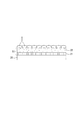
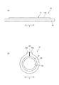
- FIG. 1 is a schematic perspective view showing a cell culture device according to a first embodiment. It is sectional drawing which expands and shows a part of culture base material. It is explanatory drawing of a balloon actuator. It is explanatory drawing which shows the operating principle of a balloon actuator. It is a top view which shows the state which set the cell culture apparatus to the fluid supply apparatus. It is sectional drawing of a fluid supply apparatus. It is sectional explanatory drawing which shows the connection part of an introductory tube and a culture base material. It is a plane explanatory view of a balloon actuator concerning a 2nd embodiment. It is explanatory drawing which shows the operating principle of a balloon actuator. It is a plane explanatory view of a balloon actuator concerning a 3rd embodiment.
- FIG. 1 is a schematic view of a cell culture apparatus according to the first embodiment.
- the cell culture device 10 of the present embodiment imitates an organ formed in a tubular shape using artificially cultured cells, and fluids such as a drug solution flow in the mimicked organ, so that the cultured cells in the organ It tries to reproduce the reaction.
- an intestinal tract, a blood vessel, etc. are mentioned as a tubular organ.
- the cell culture device 10 of this embodiment exemplifies a device that imitates the intestine as a tubular organ.
- a cell culture device 10 capable of performing evaluation of absorbability of drugs and the like for cultured cells and evaluation of permeability will be described.
- the cell culture device 10 of this embodiment can also be used to individually perform only one of the absorbability evaluation and the permeability evaluation.
- the cell culture device 10 of this embodiment includes a culture substrate 11 and a drive unit 12 that applies a driving force to the culture substrate 11 to deform the culture substrate 11.
- the culture substrate 11 is formed in a rectangular shape in plan view.
- the upper surface of the culture substrate 11 is a culture surface 11a on which cells are seeded and cultured.
- the culture substrate 11 can be elastically deformed.
- the culture substrate 11 is opened and closed by the drive unit 12.
- the culture substrate 11 includes a planar (flat) form (also referred to as a planar form or an open form) as shown in FIG. 1A and a tubular (cylindrical) form as shown in FIG. Shape) (also referred to as a tubular form or a closed form).
- the culture substrate 11 is formed in a tubular shape with the culture surface 11a on the inside, and can flow a fluid as indicated by an arrow inside.
- the tubular culture substrate 11 forms a flow path having an internal volume with the culture surface 11a as an inner surface.
- the culture surface 11a of the planar culture substrate 11 is largely opened to the outside as compared with the tubular culture substrate 11. That is, since the culture substrate 11 in the tubular form is formed in a tubular shape whose outer periphery is completely closed, the culture surface 11a is only opened to the outside at both ends in the tube axis direction. The material 11 is in a state where the entire culture surface 11a is opened.
- the culture base material 11 becomes a tubular form when a driving force is applied from the driving unit 12, and becomes a flat form when the driving force is released.
- the tube axis direction (cylinder axis direction) of the tubular culture substrate 11 is defined as the X direction
- the horizontal direction orthogonal to the X direction is defined as the Y direction. Therefore, the culture substrate 11 in the planar form is arranged such that each side is parallel to the X direction or the Y direction.
- FIG. 2 is an explanatory cross-sectional view showing a part of the culture substrate 11 in an enlarged manner.
- the culture substrate 11 includes a filter 21 provided on the driving unit 12 (on a balloon actuator 30 described later) and a collagen sheet 22 as an extracellular matrix (ECM) provided on the filter 21.
- the cells S are cultured on the collagen sheet 22 in a state where the culture substrate 11 is immersed in a liquid serving as a medium.
- caco-2 cells are statically cultured on the culture substrate 11 as the cells S to mimic the intestinal epithelium.
- the filter 21 is a porous membrane that can transmit a liquid containing a drug or the like.
- the filter 21 can be joined to a balloon actuator 30 (manufactured by PDMS) of the drive unit 12 to be described later, for example, formed using polycarbonate (PC), polymethyl methacrylate (PMMA), polypropylene (PP), or the like as a material. Can be used.
- the culture substrate 11 may be configured by providing an ECM directly on the drive unit 12 (balloon actuator 30).
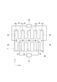
- FIG. 3 is an explanatory diagram showing the drive unit 12.
- the drive unit 12 connects the balloon actuator 30, the air supply device 36 that supplies air to the balloon actuator 30, and the balloon actuator 30 and the air supply device 36, and supplies air from the air supply device 36 to the balloon actuator 30.
- a supply pipe 37 serving as a path is provided.
- the balloon actuator 30 is elastically deformed by a change in internal air pressure, and causes the culture substrate 11 to perform a predetermined motion.
- the balloon actuator 30 of the present embodiment includes a plurality of partial actuators 31 that are elongated in the Y direction and arranged in the X direction. The plurality of partial actuators 31 are connected and integrated by a connecting portion 32 at a central portion in the Y direction.
- Each partial actuator 31 includes hollow portions 34 inside both sides in the length direction (Y direction).
- the hollow portions 34 are in communication with each other via an internal tube 35.
- the internal pipe 35 is connected to an air supply device 36 such as a compressor via a supply pipe 37.
- an air supply device 36 such as a compressor
- both end portions in the longitudinal direction of the partial actuators 31 approach each other and deform from a planar shape to a ring shape (see the right side in FIG. 3). ).
- each partial actuator 31 is held in a ring shape.
- each partial actuator 31 returns to a planar form by elastic return (see the left side of FIG. 3).
- FIG. 4 is a cross-sectional explanatory view showing the operating principle of the balloon actuator.
- the balloon actuator 30 (each partial actuator 31) is composed of a two-layer silicone rubber layer having a first film body 41 and a second film body 42, and is hollow between the first film body 41 and the second film body 42. A portion 34 is formed.
- the hollow portion 34 is configured by forming a concave portion 41 a on one or both of the opposing surfaces of the first and second film bodies 41 and 42.
- both the first film body 41 and the second film body 42 are formed of a stretchable silicone rubber, the surface area of the first film body 41 and the second film body 42 is expanded while expanding the surface area like a balloon by the pressure of air supplied into the hollow portion 34. Expands. In the balloon actuator 30, since the second film body 42 is thinner and softer than the first film body 41, the second film body 42 expands larger than the first film body 41 even under the same pressure.
- the balloon actuator 30 is bent in the same direction as the expansion direction of the first film body 41, that is, in the example of FIG. Two or more recesses 41 a may be formed in the length direction of the partial actuator 31.
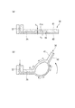
- FIG. 5 and 6 show an apparatus for flowing a fluid through the culture substrate 11 of the cell culture apparatus 10 shown in FIG.
- the cell culture device 10 is placed on the storage container 50.
- 5A shows a state in which the culture substrate 11 is in a planar form
- FIG. 5B shows a state in which the culture substrate 11 is in a tubular form.
- the storage container 50 is formed with a first pool (first storage unit) 51 and a second pool (second storage unit) 52. Liquid is stored in the first pool 51 in advance.
- a medium used for culturing cells for example, DMEM (Dulbecco's modified Eagle medium) can be used.
- the tubular culture substrate 11 is immersed in the liquid stored in the first pool 51.
- DMEM Dulbecco's modified Eagle medium
- the culture substrate 11 and the balloon actuator 30 are largely bent before and after the first pool 51, but actually, the culture substrate 11 and the balloon actuator 30 are immersed in the first pool 51 in a smoothly curved state.
- physiological saline such as BS (Buffered Saline) and HBSS (Hank's Balanced Salt Solution) can also be used.
- An introduction tube 53 is connected to one end of the tubular culture substrate 11.
- a drug solution containing a drug to be subjected to drug discovery screening flows through the introduction tube 53, and the drug solution is perfused into the culture substrate 11 having a tubular shape.
- the other end of the culture substrate 11 faces the second pool 52, and the chemical solution flowing out of the culture substrate 11 is stored in the second pool 52.
- the culture base material 11 is deformed into a flat form as shown in FIG.
- the state of the cultured cells after this can be easily observed.
- the inner surface of one end in the axial direction of the tubular culture substrate 11 to which the introduction tube 53 is connected is subjected to water repellent treatment.
- the inner surface of the end portion of the culture substrate 11 is coated with a water repellent film 54 such as a parylene film. Therefore, it is possible to prevent the chemical solution flowing into the culture substrate 11 from the introduction tube 53 from flowing back into the introduction tube 53 or leaking.
- the culture substrate 11 is deformed from a planar form to a tubular form when a driving force is applied from the balloon actuator 30 and is elastically restored by releasing the driving force from the balloon actuator 30. It deformed from a tubular form to a planar form.
- the driving force from the balloon actuator 30 is applied even when the tubular form is deformed to the flat form.
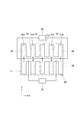
- the balloon actuator 30 includes two types of partial actuators 31a and 31b.
- One partial actuator 31a is the same as that of the first embodiment, and as shown in FIG. 4B, the air is supplied to the hollow portion 34 and bends upward.
- the other partial actuator 31 b is bent downward when air is supplied to the hollow portion 34.
- the other partial actuator 31b is arranged one by one at both ends in the X direction, and a plurality of one partial actuator 31a are arranged between the partial actuators 31b at both ends.
- the partial actuator 31b is composed of a third film body 61 and a fourth film body 62, and both film bodies 61, 62 are composed of PDMS.
- the thickness t 3 of the third film body 61 where the recess 61 a is formed is larger than the thickness t 4 of the fourth film body 62, and the hardness of the third film body 61 is greater than that of the fourth film body 62. Is also high. This is the same as the relationship between the first film body 41 and the second film body 42 in the partial actuator 31a.
- the thickness t 3 of the third film body 61 of the partial actuator 31b is larger than the thickness t 1 (see FIG. 4) of the first film body 41 of the partial actuator 31a, and the hardness is also higher.
- air is supplied to the partial actuator 31b from an air supply device 38 (see FIG. 8) different from the partial actuator 31a.
- Part actuator 31b when the hollow portion 34 of air is supplied, most elongation not occur in the third film body 61, the stress F 3 tensile occurs in the third film body 61 is small. On the other hand, since the fourth film body 62 expands and expands greatly, a tensile stress F 4 larger than the tensile stress F 3 generated in the third film body 61 is generated. For this reason, the partial actuator 31b bends downward.
- the air supply device 36 when the culture substrate 11 is deformed from the flat form to the tubular form, only the air supply device 36 operates to cause the partial actuator 31a to bend and move the culture substrate 11.
- the air supply device 38 When the actuator is deformed from the tubular form to the planar form, only the air supply device 38 operates to cause the partial actuator 31b to bend. Therefore, not only when deforming from a flat form to a tubular form, but also when deforming from a tubular form to a flat form, the driving force from the balloon actuator 30 acts on the culture substrate 11, and rapid deformation is possible. It has become.
- the partial actuators 31b are provided only at both ends in the X direction of the culture substrate 11, and the partial actuators 31a are provided in most other parts. Therefore, it is possible to apply a larger driving force when deforming from a planar form to a tubular form, and it is possible to deform the tubular form more quickly and to maintain the tubular form with certainty. Further, the partial actuator 31b does not adversely affect the cells cultured on the culture substrate 11 because the third film body 61 on the culture substrate 11 side hardly expands.
- FIG. 10 is an explanatory plan view of a balloon actuator according to the third embodiment.
- the balloon actuator 30 according to this embodiment includes two types of partial actuators 31a and 31b as in the second embodiment, but one partial actuator 31a and the other partial actuator 31b are alternately arranged in the X direction. Is arranged.
- the driving force can be imparted to the culture substrate 11 in a balanced manner. it can.
- a partial actuator 31a that is upside down may be used as the partial actuator 31b. In this case, the partial actuator 31b bends in the reverse direction (downward) on the same operating principle as shown in FIG. 4, and applies a driving force to the culture substrate 11 when it is deformed from the tubular form to the flat form. can do.
- the second film body 42 that expands more greatly is disposed on the culture surface 11a side, a portion having little influence on the culture of cells, for example, as shown in FIG. It is preferable to arrange the partial actuators 31b at both ends.
- the contact surface (seal surface) of both end portions 30a of the balloon actuator 30 is subjected to water repellent treatment.
- a film 66 having water repellency can be provided on the sealing surface.
- the water repellent treatment is required not to inhibit the adsorption between the seal surfaces.
- FIG. 12 is a cross-sectional view of the cell culture device according to the fifth embodiment.
- the culture substrate 11 in the open configuration is curved in an arc shape
- the culture substrate 11 in the closed configuration has a form curved with a smaller arc radius than the culture substrate 11 in the open form.
- the culture substrate 11 in the closed form is in a form in which both ends in the Y direction are not in contact with each other and a gap is formed between the both ends. Even in such a closed form, it can be said that the culture substrate 11 is tubular, and a flow path having an internal volume with the culture surface 11a as an inner surface is formed. Therefore, the fluid can be perfused as in the first embodiment.
- FIG. 13 is a cross-sectional view of the cell culture device according to the sixth embodiment.
- two support members 71 formed in a semicircular arc shape are provided, and the culture substrate 11 having the culture surface 11 a is provided on the inner surface of each support member 71.
- One end portions of the two support members 71 are rotatably connected to each other by a hinge portion 72.
- Each support member 71 has rigidity enough to maintain a semicircular arc shape.
- cultivation base material 11 can be deform
- the culture substrate 11 can be transformed into an open form by separating the other end portions of the two support members 71 from each other.
- a channel is formed by the culture substrate 11 in the closed form, and fluid can be perfused through the channel.
- the culture substrate 11 in the open form can suitably perform cell culture and observation.
- the culture substrate 11 is moved between the closed configuration and the open configuration by rotating the two support members 71 using a drive unit (not shown) including a motor, a fluid pressure cylinder, and the like. Can be deformed.
- the support member 71 can be formed of, for example, a synthetic resin material, and may have a permeation region that allows the liquid that has permeated the culture substrate 11 to pass through, as in the first embodiment.
- the culture substrate 11 can be opened and closed between the closed configuration shown in FIG. 14 (b) and the open configuration shown in FIG. 14 (a), and the culture surface 11a of the culture substrate 11 in the open configuration is
- the culture surface 11a of the culture substrate 11 in the closed configuration is more open than the culture surface 11a. Therefore, it is possible to suitably perform culture and observation on the culture surface 11a of the culture substrate 11 in the open form.
- the culture substrate 11 can be closed and opened by rotating a part 73b of the support member 73 using a drive unit (not shown) including a motor, a fluid pressure cylinder, and the like. Can be deformed between.
- the support member 73 may have a permeable region that allows the liquid that has passed through the culture substrate 11 to pass through, as in the first embodiment.
- the drive unit 12 that deforms the culture substrate 11 is not limited to the one using the balloon actuator 30, and the culture substrate 11 is deformed between a tubular form (closed form) and a planar form (open form).
- Other configurations may be used as long as possible.
- the drive unit 12 performs another motion, for example, a motion simulating a peristaltic motion performed by a tubular organ. Also good.
- the plurality of partial actuators 31 of the first embodiment can be individually driven, and can be realized by sequentially contracting in the X direction.
- the culture substrate 11 in the tubular form may not be a perfect circle in cross section, but may be an elliptical shape or a flat circular shape.
- the transmission region 33 formed in the balloon actuator 30 is not limited to being formed in a notch shape, and may be formed in a hole shape penetrating the balloon actuator 30 in the thickness direction. Moreover, when not evaluating the permeability
- the inventor of the present application examined the influence of the opening / closing operation of the culture substrate by the balloon actuator on the cells on the culture substrate. Specifically, caco-2 cells that mimic the intestinal epithelium were cultured on a culture substrate. DS Pharma Biomedical Co., Ltd. was used for caco-2 cells. Supplemented with 10% heat-inactivated fetal bovine serum, penicillin G (100 UmL ⁇ 1 ), streptomycin (100 ⁇ g mL ⁇ 1 ), and 1% non-essential amino acids in an environment of 37 ° C., 5% CO 2 and 95% air Caco-2 cells were cultured in DMEM (Dulbecco's modified Eagle medium).
- DMEM Dulbecco's modified Eagle medium
- Caco-2 cells were passaged by dissociation in 0.05% trypsin and EDTA, and the cells were seeded on the collagen constituting the culture substrate on the upper surface of the balloon actuator. Caco-2 cells reached confluence in 7 days. The medium was changed every 24 hours.
- the balloon actuator was used in a form of sealing when the culture substrate was formed in a tubular shape and both end portions were overlapped with each other.
- a balloon actuator having a shape that does not have a permeable region for allowing liquid to permeate and covers the entire outside of the culture substrate was used.
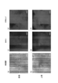
- FIG. 15 shows an image of the surface of the culture substrate.
- FIG. 15 (a) shows a state after the upper surface of the balloon actuator is coated with collagen
- FIG. 15 (b) shows a state where cells are seeded
- FIG. 15 (c) shows that caco-2 cells are statically cultured.
- FIG. 15 (d) shows a state after staining with calcein AM after static culturing of caco-2 cells
- FIG. 15 (e) shows a state after repeatedly operating the balloon actuator ten times
- FIG. 15 (f) shows a state stained with calcein AM after the balloon actuator has been repeatedly operated 10 times.
- the U-shaped line projected on the image indicates the peripheral edge of the hollow portion of the balloon actuator.
- FIG. 15 (b) As a result of the above operation, as shown in FIG. 15 (b), the caco-2 cells adhered to the surface of the culture substrate, and the monolayer caco-2 cells were normally formed on the culture substrate. It could be confirmed. It was also confirmed that there was no detachment of caco-2 cells even after the balloon actuator was operated 10 times (see FIGS. 15 (c) and (e)). These results indicate that cell viability is maintained and that the caco-2 cells are firmly attached to the culture substrate during repeated actuation of the balloon actuator. Moreover, it was confirmed that the caco-2 cells on the culture substrate were uniformly stained with calcein AM (see FIGS. 15 (d) and 15 (f)). This indicates that monolayer caco-2 cells are firmly formed by cell-cell junctions. In addition, when fluid was flowing through the tubular culture substrate, fluid leakage did not occur.
- FIG. 16 is a microscopic image of caco-2 cells.
- FIGS. 16A and 16B are bright field images of the bottom and top of a tubular culture substrate. From this image, it was confirmed that the caco-2 cells were not detached due to the shear stress accompanying the perfusion of the drug solution.
- FIGS. 16C and 16D are images obtained by imaging the fluorescence signal of calcein at the bottom and top of the tubular culture substrate
- FIGS. 16E and 16F are images of the fluorescence signal of Texas Red. It is an image. From these images, it was confirmed that calcein and Texas red were uniformly absorbed by caco-2 cells regardless of the degree of hydrophilicity.
- FIG. 17 is an image showing a plurality of types of culture substrates and balloon actuators having different inner diameters.
- FIG. 17A shows a culture substrate having an inner diameter of about 0.5 mm
- FIG. 17B shows an inner diameter of about 1.0 mm
- FIG. 17C shows an inner diameter of about 2.0 mm.
- FIG. 22 is a table showing the relationship between the inner diameter of a tubular culture substrate (hereinafter also simply referred to as “tube”) and the mechanical properties of the fluid flowing through the tube.
- the flow velocity u, the shear stress ⁇ , the pressure drop ⁇ P, and the Reynolds number Re are calculated by the following equations (1) to (4), respectively.
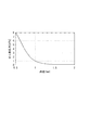
- FIG. 18 shows the relationship between the inner diameter of the tube and the shear stress.
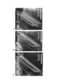
- FIG. 19 shows images obtained by flowing a fluid containing Texas Red as a lipophilic drug model through three types of tubular culture substrates having different inner diameters, and imaging a fluorescence signal of Texas Red.
- 19A shows a case where the inner diameter is 0.5 mm
- FIG. 19B shows a case where the inner diameter is 1.0 mm
- FIG. 19C shows a case where the inner diameter is 2.0 mm.
- the inner diameter of the tubular culture substrate is 0.5 mm and 1.0 mm
- the former is imaged more red than the latter, and the inner diameter is 1.0 mm and 2.0 mm.
- the former was imaged more red than the latter. Therefore, it can be said that the smaller the inner diameter of the tube, the faster the lipophilic drug is absorbed.
- FIG. 20 shows images obtained by flowing a fluid containing calcein as a hydrophilic drug model through three types of tubular culture substrates having different inner diameters, and capturing fluorescence signals of calcein.
- 20A shows the case where the inner diameter is 0.5 mm
- FIG. 20B shows the case where the inner diameter is 1.0 mm
- FIG. 20C shows the case where the inner diameter is 2.0 mm.
- the inner diameter of the tubular culture substrate was any, the state of caco-2 cell staining did not change, and there was almost no difference in the rate of absorption of the hydrophilic drug.
- the shear stress ⁇ decreases as the inner diameter r of the tubular culture substrate increases, and the shear stress ⁇ increases as the inner diameter r decreases. Therefore, the greater the inner diameter r, the greater the mucin layer thickness.
- the thickness T is large and the absorption of the lipophilic drug is delayed (see FIG. 21 (a)).
- the smaller the inner diameter r the smaller the thickness T of the mucin layer and the faster the absorption of the lipophilic drug (FIG. 21 (b)). Reference). Therefore, it can be said that the rate of lipophilic drug absorption can be controlled by controlling the shear stress by adjusting the inner diameter of the tubular culture substrate.
- various flow states of the tube in the living body can be reproduced, and the speed of absorption of the lipophilic drug can also be reproduced.
Abstract
Description
従来、このような培養細胞は、ディッシュ上やマイクロウェル内で培養されるのが一般的である。また、最近ではより生体に近い状態で細胞を培養することにより臓器を模したオンチップ臓器も開発されている(例えば、特許文献1参照)。
しかしながら、ディッシュ上やマイクロウェル内で細胞を二次元的に培養した場合、必ずしも生体内で起こる反応を再現できない。例えば、腸管内を薬剤を含む液体(薬液)が流動することを想定して二次元的に培養された細胞上に薬液を流したとしても、その細胞全体に均一に流体が作用せず、流体の流れに起因する剪断力等の機械的な力を細胞に適切に付与することができない。そのため、細胞に薬剤が吸収され、透過する過程を正確に再現することは困難である。
細胞が培養される培養面を有する培養基材と、
前記培養基材を閉形態と開形態との間で開閉運動させる駆動部とを備え、
前記閉形態は、前記培養基材が、前記培養面を内面とした内部容積をもつ流路を形成する形態であり、
前記開形態は、前記培養基材の前記培養面が、前記閉形態における前記培養基材の前記培養面よりも開放された形態である。
これにより、従来と同様の態様により細胞の培養や観察等を行うことができる。
このような構成によって、腸管等の生体の器官を模様することができ、薬液等を流したときの反応を忠実に再現することができる。なお、ここでいう管状とは、外周全体が閉じた形態である場合だけでなく、外周の一部が開放された形態であってもよい。
このような構成によって、駆動部を簡素に構成することができる。
このような構成によって、培養基材を透過した液体は、駆動部のバルーンアクチュエータを通り抜けて培養基材外へ排出される。そのため、例えば、閉形態の培養基材内を流れる薬液等が細胞に吸収され、透過した後の状態を評価することができる。
このような構成によって、管状の培養基材内に薬液等を流動させたときの漏れを防止することができる。
このような構成によって、管状の培養基材内に薬液等を流動させたときの漏れをより確実に防止することができる。
このような構成によって、培養基材から管への液体の逆流を抑制することができる。
[第1の実施形態]
図1は、第1の実施形態に係る細胞培養装置の概略図である。
本実施形態の細胞培養装置10は、人工的に培養した細胞を用いて管状に形成された器官を模倣し、模倣した器官内に薬液等の流体を流動させることで、当該器官における培養細胞の反応を再現しようとするものである。例えば、管状の器官として腸管や血管などが挙げられる。本実施形態の細胞培養装置10は、特に、管状の器官として腸管を模倣したものを例示する。また、本実施形態では、培養細胞に対する薬剤等の吸収性の評価と、透過性の評価とを行うことが可能な細胞培養装置10について説明する。ただし、本実施形態の細胞培養装置10は、吸収性評価及び透過性評価のいずれか一方のみを個別に行うために用いることもできる。
培養基材11は、平面視で矩形状に形成されている。培養基材11の上面は、細胞が播種され、かつ培養される培養面11aとされている。また、培養基材11は、弾性変形可能である。
以下の説明においては、管状形態の培養基材11の管軸方向(筒軸方向)をX方向とし、このX方向に直交する水平方向をY方向とする。したがって、平面形態の培養基材11は、各辺がX方向又はY方向と平行に配置される。
駆動部12は、バルーンアクチュエータ30と、バルーンアクチュエータ30に空気を供給する空気供給装置36と、バルーンアクチュエータ30と空気供給装置36とを接続し、空気供給装置36からバルーンアクチュエータ30への空気の供給路となる供給管37とを備えている。バルーンアクチュエータ30は、内部の空気圧の変化によって弾性変形し、培養基材11に所定の運動を行わせる。本実施形態のバルーンアクチュエータ30は、Y方向に細長く形成された複数の部分アクチュエータ31をX方向に並べて備えている。複数の部分アクチュエータ31は、Y方向の中央部において連結部32によって連結され、一体化されている。隣接する部分アクチュエータ31の間には、Y方向の外端縁から内側へ向けて切り欠け状に形成された透過領域33が形成される。したがって、培養基材11を透過した液体は、透過領域33を介してバルーンアクチュエータ30を通り抜けることができる。
バルーンアクチュエータ30(各部分アクチュエータ31)は、第1膜体41と第2膜体42とを有する2層のシリコーンラバー層からなり、第1膜体41と第2膜体42との間に中空部34が形成されている。中空部34は、第1及び第2膜体41,42の対向面の一方又は両方に、凹部41aを形成することによって構成される。
さらに、培養基材を管状形態にして薬液を環流させ、その後、培養基材を平面形態にして細胞の観察を行うという操作を繰り返し行うことも可能である。
上述した第1の実施形態では、培養基材11は、バルーンアクチュエータ30から駆動力が作用することによって平面形態から管状形態に変形し、バルーンアクチュエータ30からの駆動力を解除することによって弾性復帰により管状形態から平面形態に変形するものであった。第2の実施形態では、管状形態から平面形態に変形する際にもバルーンアクチュエータ30からの駆動力を付与するものとなっている。
また、部分アクチュエータ31bは、培養基材11側の第3膜体61はほとんど膨張しないので、培養基材11に培養された細胞に悪影響を及ぼすこともない。
図10は、第3の実施形態に係るバルーンアクチュエータの平面説明図である。この実施形態に係るバルーンアクチュエータ30は、第2の実施形態と同様に、2種類の部分アクチュエータ31a,31bを備えているが、一方の部分アクチュエータ31aと他方の部分アクチュエータ31bとがX方向に関して交互に配置されている。
なお、第2及び第3の実施形態においては、部分アクチュエータ31bとして、部分アクチュエータ31aを表裏反転したものを使用してもよい。この場合、部分アクチュエータ31bは、図4に示すものと同様の作動原理で逆方向(下方向)に曲がり運動を行い、管状形態から平面形態に変形するときに培養基材11に駆動力を付与することができる。ただし、この場合、より大きく膨張する第2膜体42が培養面11a側に配置されることになるので、細胞の培養への影響が少ない箇所、例えば、図8に示すように、X方向の両端部に部分アクチュエータ31bを配置することが好ましい。
図11は、第4の実施形態に係る細胞培養装置の断面図である。
本実施形態では、図11(a)に示すように、バルーンアクチュエータ30のY方向の幅は、培養基材11の幅よりも大きく形成されている。そして、図11(b)に示すように、培養基材11を管状形態に変形させると、バルーンアクチュエータ30のY方向の両端部30aが管状形態の培養基材11から径方向外方へ突出して互いに重ね合わされ、面接触した状態となる。これによって、管状形態の培養基材11の内部に流体を流したときの漏れが防止される。
図12は、第5の実施形態に係る細胞培養装置の断面図である。
本実施形態では、図12(a)に示すように、開形態における培養基材11が、円弧状に湾曲した形態であり、図12(b)に示すように、閉形態における培養基材11が、開形態における培養基材11よりも小さい円弧半径で湾曲した形態となっている。
なお、本実施形態においても、開形態の培養基材11は、第1の実施形態と同様に平面状に形成されてもよい。逆に、第1の実施形態における開形態の培養基材11が、本実施形態のようにわずかに湾曲していてもよい。また、閉形態の培養基材11は、液体を灌流させることが可能な程度に湾曲していればよいが、管状形態の中心軸回りに180°を超える範囲で湾曲した形態とすることが好適である。
図13は、第6の実施形態に係る細胞培養装置の断面図である。
本実施形態では、半円弧状に形成された2つの支持部材71が設けられ、各支持部材71の内面に培養面11aを有する培養基材11が設けられている。2つの支持部材71の一端部同士は、ヒンジ部72によって互いに回動自在に連結されている。各支持部材71は、半円弧状の形態を維持できる程度の剛性を有したものとされる。そして、図13(b)に示すように、2つの支持部材71の他端部同士を突き合わせることによって培養基材11を閉形態(管状形態)に変形することができ、図13(a)に示すように、2つの支持部材71の他端部同士を離反させることによって培養基材11を開形態に変形することができる。
なお、本実施形態においては、モータや流体圧シリンダ等からなる駆動部(図示省略)を用いて2つの支持部材71を回転させることにより、培養基材11を閉形態と開形態との間で変形させることができる。支持部材71は、例えば合成樹脂材により形成することができ、第1の実施形態等と同様に、培養基材11を透過した液体を通り抜けさせることができる透過領域を有していてもよい。
図14は、第7の実施形態に係る細胞培養装置の斜視図である。
本実施形態では、図14(b)に示すように、管状(筒状)に形成された支持部材73の内側に培養基材11が設けられており、培養基材11の内部に流路が形成されている。また、本実施形態では、支持部材73の一部73bと、その内側の培養基材11の一部11bとは、ヒンジ部74を介して他の部分に対して回動可能に構成されている。
なお、本実施形態においても、モータや流体圧シリンダ等からなる駆動部(図示省略)を用いて支持部材73の一部73bを回転させることにより、培養基材11を閉形態と開形態との間で変形させることができる。支持部材73は、第1の実施形態等と同様に、培養基材11を透過した液体を通り抜けさせることができる透過領域を有していてもよい。
例えば、培養基材11を変形させる駆動部12は、バルーンアクチュエータ30を用いたものに限定されず、培養基材11を管状形態(閉形態)と平面形態(開形態)との間で変形させることができる限り、他の構成を用いてもよい。
管状形態の培養基材11は、断面形状が真円でなくてもよく、楕円形や扁平な円形状であってもよい。
また、培養細胞に対する液体の透過性を評価しない場合には、培養基材11の培養面11aとは反対側の全体を覆うようにバルーンアクチュエータ30を設けてもよい。この場合、培養細胞の液体の吸収性評価を行うことができる。
本出願の発明者は、バルーンアクチュエータによる培養基材の開閉動作が培養基材上の細胞に与える影響について調べた。
具体的には、培養基材上に、腸管上皮を模倣するcaco-2細胞を培養した。caco-2細胞には、DSファーマバイオメディカル株式会社製を用いた。37℃、CO25%、空気95%の環境下で、10%熱不活性ウシ胎児血清、ペニシリンG(100UmL-1)、ストレプトマイシン(100μg mL-1)、および、1%非必須アミノ酸を補充したDMEM(ダルベッコ改変イーグル培地)内でcaco-2細胞を培養した。caco-2細胞は、0.05%トリプシンおよびEDTA中で解離することによって継代し、バルーンアクチュエータの上面において培養基材を構成するコラーゲン上に細胞を播種した。caco-2細胞は、7日間でコンフルーエンスに達した。培地は24時間毎に交換した。
次に、本出願の発明者は、管状形態の培養基材に薬剤が均一に流れ、caco-2細胞に均一に吸収されるかを調べた。
管状形態の培養基材には、薬液に相当する液体として蛍光色素を含むHBSS(Hanks' Balanced Salt Solution)を0.05mLmin-1の流量で1時間灌流した。蛍光色素には、親水性薬剤のモデルとしてのカルセインと、親油性薬剤のモデルとしてのテキサスレッドとを用い、それぞれの濃度を100μmolL-1,10μmolL-1とした。その後、管状形態の培養基材の底部および上部におけるcaco-2細胞の明視野画像と蛍光画像とを観察した。
本出願の発明者は、管状形態の培養基材に薬液等の液体を流したときの、流体の力学的特性および培養基材への薬剤の吸収について調べた。具体的には、内径が異なる複数種類の管状形態の培養基材に対して薬剤を含む流体を流し、流体を流す前後の培養基材の状態を観察した。また、管状形態の各培養基材における流体の力学的特性を演算により求めた。
図22は、管状形態の培養基材(以下、単に「管」ともいう)の内径と、管を流れる流体の力学的特性との関係を示す表である。この表において、流速u、せん断応力τ、圧力降下ΔP、レイノルズ数Reは、それぞれ次の式(1)~(4)によって演算される。
τ=4μQ/(πr3) ・・・ (2)
ΔP=8μQL/(πr4) ・・・ (3)
Re=2ρQ/(μπr) ・・・ (4)
ただし、Qは液体の流量、μは液体の粘度、ρは液体の密度、Lは管の長さ、rは管の半径である。液体の流量Qは、0.05mL/minとし、3分間液体を灌流させた。
また、図19は、内径が異なる3種類の管状形態の培養基材に、親油性薬剤のモデルとしてテキサスレッドを含む流体を流し、テキサスレッドの蛍光信号を撮像した画像を示す。図19(a)は、内径が0.5mmの場合、(b)は内径が1.0mmの場合、(c)は、内径が2.0mmの場合である。管状形態の培養基材の内径が0.5mmの場合と1.0mmの場合とを比較すると、前者の方が後者よりもより赤く撮像され、内径が1.0mmの場合と2.0mmの場合とを比較すると、前者の方が後者よりもより赤く撮像された。したがって、管の内径が小さい程、より速く親油性薬剤が吸収されているといえる。
図21に示すように、培養基材に培養されたcaco-2細胞からは、粘性の高いムチンが分泌され、caco-2細胞の表面が親水性のムチン層(粘液層)で覆われる。このムチン層は非撹拌水層とも呼ばれ、caco-2細胞への親油性薬剤の吸収を妨げる障壁となる一方、親水性薬剤の吸収は妨げない。また、ムチン層は、流体の流れによって培養基材の内面に作用するせん断応力によって厚さTが変化すると考えられる。図22に示すように、管状形態の培養基材の内径rが大きい程せん断応力τは小さくなり、内径rが小さい程せん断応力τが大きくなるので、当該内径rが大きい程、ムチン層の厚さTが大きく親油性薬剤の吸収が遅くなり(図21(a)参照)、当該内径rが小さい程、ムチン層の厚さTが小さく親油性薬剤の吸収が速くなる(図21(b)参照)と考えることができる。したがって、管状形態の培養基材の内径を調整することによってせん断応力をコントロールすれば、親油性薬剤の吸収の速さをコントロールすることが可能であるといえる。また、管状形態の培養基材の内径を調整することによって、生体における管の様々な流れの状態を再現することができ、親油性薬剤の吸収の速さも再現することができると考えられる。
11 :培養基材
11a :培養面
12 :駆動部
30 :バルーンアクチュエータ
30a :両端部
53 :導入管
S :細胞
Claims (8)
- 細胞が培養される培養面を有する培養基材と、
前記培養基材を閉形態と開形態との間で開閉させる駆動部とを備え、
前記閉形態は、前記培養基材が、前記培養面を内面とした内部容積をもつ流路を形成する形態であり、
前記開形態は、前記培養基材の前記培養面が、前記閉形態における前記培養基材の前記培養面よりも外部に開放された形態である、細胞培養装置。 - 前記開形態の前記培養基材が平坦に形成される、請求項1に記載の細胞培養装置。
- 前記閉形態の前記培養基材が管状に形成される、請求項1又は2に記載の細胞培養装置。
- 前記駆動部が、前記培養基材における前記培養面とは反対側の面に設けられたバルーンアクチュエータを有している、請求項1~3のいずれか1項に記載の細胞培養装置。
- 前記バルーンアクチュエータは、前記培養基材を透過した液体が通り抜ける領域を有している、請求項4に記載の細胞培養装置。
- 前記閉形態の前記培養基材が管状に形成され、
前記閉形態の前記培養基材において、互いに対向する前記バルーンアクチュエータの両端部における前記培養基材側の面が、互いに面接触するシール面を構成している、請求項4又は5に記載の細胞培養装置。 - 前記シール面に撥水処理が施されている、請求項6に記載の細胞培養装置。
- 前記閉形態の前記培養基材に流体を流入させるための導入管が接続される、当該培養基材の端部の内周面に、撥水処理が施されている、請求項1~7のいずれか1項に記載の細胞培養装置。
Priority Applications (2)
| Application Number | Priority Date | Filing Date | Title |
|---|---|---|---|
| US15/747,449 US20180282679A1 (en) | 2015-07-28 | 2016-07-26 | Cell culture apparatus |
| JP2017530878A JP6712082B2 (ja) | 2015-07-28 | 2016-07-26 | 細胞培養装置 |
Applications Claiming Priority (2)
| Application Number | Priority Date | Filing Date | Title |
|---|---|---|---|
| JP2015-148789 | 2015-07-28 | ||
| JP2015148789 | 2015-07-28 |
Publications (1)
| Publication Number | Publication Date |
|---|---|
| WO2017018413A1 true WO2017018413A1 (ja) | 2017-02-02 |
Family
ID=57885677
Family Applications (1)
| Application Number | Title | Priority Date | Filing Date |
|---|---|---|---|
| PCT/JP2016/071879 WO2017018413A1 (ja) | 2015-07-28 | 2016-07-26 | 細胞培養装置 |
Country Status (3)
| Country | Link |
|---|---|
| US (1) | US20180282679A1 (ja) |
| JP (1) | JP6712082B2 (ja) |
| WO (1) | WO2017018413A1 (ja) |
Citations (2)
| Publication number | Priority date | Publication date | Assignee | Title |
|---|---|---|---|---|
| US20050095711A1 (en) * | 2003-11-01 | 2005-05-05 | More Robert B. | Bioreactor for growing engineered tissue |
| JP2014506801A (ja) * | 2011-02-28 | 2014-03-20 | プレジデント・アンド・フェロウズ・オブ・ハーバード・カレッジ | 細胞培養システム |
Family Cites Families (2)
| Publication number | Priority date | Publication date | Assignee | Title |
|---|---|---|---|---|
| US20100041128A1 (en) * | 2008-01-08 | 2010-02-18 | Medtrain Technologies, Llc | Microfluidic Device for Application of Shear Stress and Tensile Strain |
| US20130267929A1 (en) * | 2010-10-25 | 2013-10-10 | Kyoto University | Method for operating a device for delivering a substance to be introduced, and method for delivering a substance to be introduced |
-
2016
- 2016-07-26 US US15/747,449 patent/US20180282679A1/en not_active Abandoned
- 2016-07-26 WO PCT/JP2016/071879 patent/WO2017018413A1/ja active Application Filing
- 2016-07-26 JP JP2017530878A patent/JP6712082B2/ja active Active
Patent Citations (2)
| Publication number | Priority date | Publication date | Assignee | Title |
|---|---|---|---|---|
| US20050095711A1 (en) * | 2003-11-01 | 2005-05-05 | More Robert B. | Bioreactor for growing engineered tissue |
| JP2014506801A (ja) * | 2011-02-28 | 2014-03-20 | プレジデント・アンド・フェロウズ・オブ・ハーバード・カレッジ | 細胞培養システム |
Non-Patent Citations (2)
| Title |
|---|
| BHATIA, S. N. ET AL.: "Microfluidic organs-on-chips", NATURE BIOTECHNOLOGY, vol. 32, no. 8, 2014, pages 760 - 772, XP002761628, ISSN: 1087-0156 * |
| SUGIURA, S. ET AL.: "Microfluidic serial dilution cell -based assay for analyzing drug dose response over a wide concentration range", ANALYTICAL CHEMISTRY, vol. 82, no. 19, 2010, pages 8278 - 8282, XP055350099, ISSN: 0003-2700 * |
Also Published As
| Publication number | Publication date |
|---|---|
| JP6712082B2 (ja) | 2020-06-17 |
| JPWO2017018413A1 (ja) | 2018-05-17 |
| US20180282679A1 (en) | 2018-10-04 |
Similar Documents
| Publication | Publication Date | Title |
|---|---|---|
| Shaegh et al. | Rapid prototyping of whole-thermoplastic microfluidics with built-in microvalves using laser ablation and thermal fusion bonding | |
| Guan et al. | Medical devices on chips | |
| Tanaka et al. | A micro-spherical heart pump powered by cultured cardiomyocytes | |
| US10926254B2 (en) | Membrane-integrated microfluid device for imaging cells | |
| Borenstein et al. | Microfabrication technology for vascularized tissue engineering | |
| JP6423082B2 (ja) | 細胞培養装置および細胞培養方法 | |
| US20160244727A1 (en) | Artificial microvascular device and methods for manufacturing and using the same | |
| JP4981374B2 (ja) | 細胞又は組織の培養装置及び培養方法 | |
| Kim et al. | Microfluidic biomechanical device for compressive cell stimulation and lysis | |
| CA2728385C (en) | Device for investigation of a flow conduit | |
| US20190093059A1 (en) | Cell culture device and cell culture method | |
| CN103805511B (zh) | 可在高倍物镜下直接观测的动脉血管模拟微流控装置 | |
| Li et al. | Selective stamp bonding of PDMS microfluidic devices to polymer substrates for biological applications | |
| Hosic et al. | Rapid prototyping of multilayer microphysiological systems | |
| KR102345370B1 (ko) | 혈관 모델 | |
| US20130344529A1 (en) | Vascular model, method for producing said model and use thereof | |
| US10106768B2 (en) | Micro cell culturing device | |
| US20190093058A1 (en) | Cell culture device and cell culture method | |
| Brewer et al. | A microfluidic cell co-culture platform with a liquid fluorocarbon separator | |
| Wang et al. | Bio-MEMS fabricated artificial capillaries for tissue engineering | |
| Palaninathan et al. | Multi-organ on a chip for personalized precision medicine | |
| WO2017018413A1 (ja) | 細胞培養装置 | |
| KR101569619B1 (ko) | 수축 및 팽창 기능을 하는 인체장기를 모사한 실험모델장치 | |
| Sonntag et al. | Universal lab-on-a-chip platform for complex, perfused 3D cell cultures | |
| US20220195486A1 (en) | Multiplexable microfluidic culture chamber for imaging monolayer growth of single cells |
Legal Events
| Date | Code | Title | Description |
|---|---|---|---|
| 121 | Ep: the epo has been informed by wipo that ep was designated in this application |
Ref document number: 16830518 Country of ref document: EP Kind code of ref document: A1 |
|
| ENP | Entry into the national phase |
Ref document number: 2017530878 Country of ref document: JP Kind code of ref document: A |
|
| NENP | Non-entry into the national phase |
Ref country code: DE |
|
| WWE | Wipo information: entry into national phase |
Ref document number: 15747449 Country of ref document: US |
|
| 122 | Ep: pct application non-entry in european phase |
Ref document number: 16830518 Country of ref document: EP Kind code of ref document: A1 |