WO2017018104A1 - ワークを垂直状態に保持するバリ取り装置及び板材加工システム - Google Patents
ワークを垂直状態に保持するバリ取り装置及び板材加工システム Download PDFInfo
- Publication number
- WO2017018104A1 WO2017018104A1 PCT/JP2016/068546 JP2016068546W WO2017018104A1 WO 2017018104 A1 WO2017018104 A1 WO 2017018104A1 JP 2016068546 W JP2016068546 W JP 2016068546W WO 2017018104 A1 WO2017018104 A1 WO 2017018104A1
- Authority
- WO
- WIPO (PCT)
- Prior art keywords
- workpiece
- deburring
- brush
- rotating
- laser processing
- Prior art date
- Legal status (The legal status is an assumption and is not a legal conclusion. Google has not performed a legal analysis and makes no representation as to the accuracy of the status listed.)
- Ceased
Links
Images




Classifications
-
- B—PERFORMING OPERATIONS; TRANSPORTING
- B24—GRINDING; POLISHING
- B24B—MACHINES, DEVICES, OR PROCESSES FOR GRINDING OR POLISHING; DRESSING OR CONDITIONING OF ABRADING SURFACES; FEEDING OF GRINDING, POLISHING, OR LAPPING AGENTS
- B24B9/00—Machines or devices designed for grinding edges or bevels on work or for removing burrs; Accessories therefor
-
- B—PERFORMING OPERATIONS; TRANSPORTING
- B24—GRINDING; POLISHING
- B24B—MACHINES, DEVICES, OR PROCESSES FOR GRINDING OR POLISHING; DRESSING OR CONDITIONING OF ABRADING SURFACES; FEEDING OF GRINDING, POLISHING, OR LAPPING AGENTS
- B24B29/00—Machines or devices for polishing surfaces on work by means of tools made of soft or flexible material with or without the application of solid or liquid polishing agents
-
- B—PERFORMING OPERATIONS; TRANSPORTING
- B24—GRINDING; POLISHING
- B24B—MACHINES, DEVICES, OR PROCESSES FOR GRINDING OR POLISHING; DRESSING OR CONDITIONING OF ABRADING SURFACES; FEEDING OF GRINDING, POLISHING, OR LAPPING AGENTS
- B24B41/00—Component parts such as frames, beds, carriages, headstocks
- B24B41/06—Work supports, e.g. adjustable steadies
Definitions
- the present invention relates to a deburring device that deburrs a plate-like workpiece processed by a plate processing machine such as a laser processing machine, and a plate processing system including the deburring device. More specifically, the present invention relates to a deburring device that performs deburring by holding a workpiece in a vertical state, and a plate material processing system that performs laser machining and bending processing while holding the workpiece in a vertical state.
- Patent Document 1 The configuration described in Patent Document 1 is a configuration in which a rotating brush for deburring a plate-like workpiece conveyed by the conveyance belt is provided at a position above a conveyance belt that can be moved horizontally so as to be movable up and down. .
- the conveyor belt has a plurality of suction holes in order to suck and hold the work placed on the transport surface.
- the rotating brush has a brush such as an elongated strip-shaped sandpaper extending in the radial direction at an appropriate interval in the circumferential direction on the outer peripheral surface of the disc-shaped brush body. I have.
- the rotating brush has a configuration in which a plurality of the brush bodies are stacked in an inclined state with respect to the rotation axis of the rotating brush.
- a conveyance belt that adsorbs and conveys a plate-like workpiece in a vertical state, and a plurality of adsorption holes for adsorbing the workpiece are provided on a vertical conveyance surface;
- a deburring device comprising a rotating brush for deburring the work, which is provided so as to be movable in a direction approaching and separating from the conveyor belt.
- the suction holes are provided closer to the upper side than to the lower side of the transport surface.
- the deburring device further includes a belt guide provided on a lower side of the conveyor belt for guiding a lower end edge of the conveyor belt.
- the deburring device includes a detection light irradiation unit configured to irradiate detection light on one side of the rotation region of the rotary brush, and the rotation region in order to detect the working diameter of the rotation brush. It further comprises a light receiving portion for receiving the detection light transmitted through the rotation region on the side.
- a laser processing machine that performs laser processing while holding a plate-shaped workpiece in a vertical state, and a bending work that holds a workpiece processed by the laser processing machine in a vertical state.
- a bending apparatus to be performed a workpiece conveying apparatus that conveys a workpiece in a vertical state from the laser processing machine to the bending apparatus, and between the laser processing machine and the workpiece conveying apparatus, or the workpiece conveying apparatus.
- a deburring device provided between the bending device and the bending device for performing deburring while holding the workpiece in a vertical state.
- a laser processing machine that holds a workpiece in a vertical state and performs laser processing
- a workpiece transfer device that holds and transfers a workpiece in a vertical state
- a bending machine that holds a workpiece in a vertical state and performs bending processing
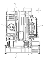
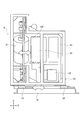
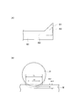
- FIG. 1 is a perspective view conceptually and schematically showing a deburring device according to an embodiment of the present invention. It is a side view of the deburring apparatus which concerns on embodiment of this invention. It is a perspective view which shows the conveyance belt in the deburring apparatus which concerns on embodiment of this invention. It is explanatory drawing of the board thickness and burr
- the plate material processing system 1 includes a vertical laser processing machine 3 that holds a plate-shaped workpiece (not shown in FIG. 1) vertically and performs laser processing, as shown in a plan view in FIG.
- a bending device 5 that performs bending while holding the workpiece in a vertical state is disposed downstream of the workpiece conveyance direction in which the workpiece processed by the vertical laser beam machine 3 is conveyed.
- a workpiece transfer device 7 is provided to transfer the workpiece from the vertical laser beam machine 3 to the bending device 5 while holding the workpiece vertically.
- a laser processing machine that performs laser processing while holding a plate-shaped workpiece vertically and a processing machine that performs workpiece punching are described in, for example, Japanese Patent Application Laid-Open Nos. 6-246474 and 8-111261. As shown, the configuration is already known.
- a bending apparatus that performs bending while holding a workpiece vertically has a known configuration as described in, for example, the above-mentioned Japanese Patent Application Laid-Open Nos. 8-121261 and 4102480. Therefore, the detailed description about the structure of the said vertical laser beam machine 3 and the bending apparatus 5 is abbreviate
- the plate material processing system including the vertical laser processing machine 3 and the bending device 5
- the plate material processing that holds the workpiece processed by the vertical laser processing machine 3 vertically and conveys it to the bending machine 5.
- the system has a known configuration as described in, for example, Japanese Patent Application Laid-Open No. 2013-112491. Therefore, the detailed description of the workpiece transfer device 7 is omitted.
- the vertical laser processing machine 3 performs laser processing while holding a plate-like workpiece vertically. Then, the workpiece processed by laser processing is held vertically by the workpiece transfer device 7 and transferred to the bending device 5 so that the workpiece can be held vertically and bent.
- the deburring device described in Patent Document 1 Japanese Patent Laid-Open No. 2009-131945
- the deburring device described in Patent Document 1 is a plate-shaped workpiece. It is the structure which deburrs by hold
- the deburring apparatus is configured to be able to perform deburring while holding a plate-like workpiece vertically.
- the deburring apparatus 9 is arrange
- the deburring device 9 may be disposed between the workpiece conveying device 7 and the bending device 5 because the workpiece needs to be deburred before being bent by the bending machine 5. It is also possible to do.
- the deburring device 9 includes a base frame 11.
- a fixed frame 13 is erected on the base frame 11.
- the fixed frame 13 is provided with an endless conveyance belt 15 having a vertical conveyance surface that adsorbs and conveys a plate-like workpiece (processing workpiece) W in a vertical state.
- the conveyor belt 15 is separated in the X-axis direction, which is the conveying direction of the workpiece W, and is provided with a rotating shaft 17 ⁇ / b> A that is vertically and rotatably provided on the fixed frame 13. 17B (the mounting state of the rotating shafts 17A and 17B with respect to the fixed frame 13 is not shown).
- the conveyor belt 15 is vertically held and guided by a plurality of guide members 19 provided perpendicular to the fixed frame 13.
- a suction box 23 having an opening on the vertical transport surface side of the transport belt 15 is disposed.
- the suction box 23 is supported by the fixed frame 13, and a suction unit (not shown) such as a suction blower is connected to the suction box 23.
- the conveyor belt 15 is provided with a plurality of suction holes 25 made up of small holes for sucking the workpiece W.
- a belt guide 27 for guiding the lower edge of the conveyor belt 15 is provided below the conveyor belt 15.
- the belt guide 27 has a function of guiding and supporting the lower end edge of the conveyor belt 15 and a function of supporting the workpiece W when the workpiece W falls from the suction surface (conveyance surface) of the conveyor belt 15. Further, in order to prevent the workpiece W from falling down away from the transport belt 15 when being sucked and transported by the transport belt 15, the suction hole 25 has an upper side than the lower side of the transport belt 15. It is prepared to be dense.
- the conveyor belt motor 29 such as a servo motor for driving the conveyor belt 15 is rotated and the suction blower is driven, the workpiece W is placed on the vertical conveyor surface of the conveyor belt 15. Adsorbed in a vertical state and can be conveyed in the X-axis direction.
- the rotary brush 31 is provided so as to be movable and adjustable in the Y-axis direction, which is a direction of approaching and moving away from the conveyor belt 15.
- the base frame 11 is provided with a guide member 33 (see FIG. 3) in the Y-axis direction.
- a moving frame 35 is supported on the guide member 33 so as to be movable in the Y-axis direction. Yes.
- the moving brush 35 is rotatably provided with the rotating brush 31. Therefore, the moving frame 35 can also be called a brush frame.
- a pair of the rotating brushes 31 are provided to face the vertical conveying surface 15F of the conveying belt 15.
- the pair of rotating brushes 31 ⁇ / b> A and 31 ⁇ / b> B are arranged on the same vertical plane parallel to the conveyance surface 15 ⁇ / b> F of the conveyance belt 15.
- the rotary shafts 37 of the rotary brushes 31 ⁇ / b> A and 31 ⁇ / b> B are inclined so that the upper side is directed to the upstream side, which is the loading direction of the workpiece W.
- the upper end side and the lower end side of the rotating shaft 37 are rotatably supported by bearings 39 attached to the moving frame 35.
- the pulleys 41 provided at the lower ends of the rotary shafts 37 are linked to the brush motors 43 attached to the moving frame (brush frame) 35, respectively.
- the rotating brush 31A located on the upstream side in the conveying direction of the workpiece W is rotated so as to feed the workpiece W, and the rotating brush 31B located on the downstream side is rotated in the reverse direction. Accordingly, the dust generated when the rotating brushes 31A and 31B come into contact with the workpiece W to be deburred is prevented from being scattered in the direction between the rotating brushes 31A and 31B and to the outside.
- the brush depth with respect to the surface of the workpiece W that is, the workpiece, corresponding to the plate thickness and material of the workpiece W
- the penetration depth of the rotating brush (the deburring depth and the working depth of the rotating brush) with respect to the W processed surface (cut surface) is adjustable. That is, the approach distances of the rotary brushes 31A and 31B with respect to the transport surface 15F of the transport belt 15 are configured to be controllable according to the plate thickness and material of the workpiece W.
- a frame moving positioning device is provided in order to control the position of the moving frame 35 in the Y-axis direction.
- a frame moving positioning device As a configuration for moving and positioning the moving frame 35 in the Y-axis direction, for example, a ball screw mechanism (not shown) is provided.
- a frame moving motor (not shown in FIGS. 2 and 3) including a servo motor is provided.
- the rotating brushes 31A and 31B provided in the moving frame 35 can be moved and positioned in the Y-axis direction.
- the moving positions of the rotary brushes 31A and 31B from the reference position in the Y-axis direction can be detected by a rotary encoder serving as a position detector provided in the frame moving motor. Therefore, by controlling the rotation of the frame moving motor, the distance between the conveying surface 15F of the conveying belt 15 and the rotating brushes 31A and 31B can be controlled to a desired distance.
- the brush depths BD1 and BD2 at which the rotating brush 31 acts on the workpiece W are adjusted in accordance with the height of the burr, that is, the plate thickness of the workpiece.
- the machining times T1 and T2 during which the rotary brush 31 is acting on the workpiece W are adjusted according to the plate thickness of the workpiece.
- the processing time during which the rotary brush 31 is acting on the workpiece W can be adjusted, and deburring can be performed more reliably. It can be carried out.
- the configuration of the rotary brush 31 is the same as the configuration of the rotary brush described in Patent Document 1 and is publicly known, but in order to facilitate understanding, the configuration of the rotary brush 31 will be schematically described.
- the rotating brush 31 includes a disc-like brush body 45 as shown in FIG.
- the brush body 45 is provided with a disk 47 for attaching to the rotating shaft 37 of the rotating brush 31, and the outer peripheral surface of the disk 47 includes a plurality of strips such as an elongated strip-shaped sandpaper extending in the radial direction.
- Brushes (abrasives) 49 are provided at equal intervals in the circumferential direction.
- the rotating brush 31 is configured by integrally attaching a plurality of brush bodies 45 to the rotating shaft 37 of the rotating brush 31 in an inclined state. . Therefore, when the rotating shaft 37 is rotated, each brush body 45 is rotated while maintaining a state inclined with respect to the rotating shaft 37, and the brush 49 acts on the workpiece to deburr the workpiece. Done.
- a brush diameter detector 51 In order to detect the diameters of the rotating brushes 31A and 31B, a brush diameter detector 51 (see FIG. 7) is provided.
- the brush diameter detection unit 51 optically detects the brush diameter.
- one side of the rotating brushes 31A and 31B has, for example, detection of laser light or the like.
- Detection light irradiation units 53A, 53B, 53C, and 53D such as a laser diode (LD) that irradiates (incides) the light LB to the rotation regions of the rotating brushes 31A and 31B are arranged in the same plane.
- a plurality of light receiving portions 55A, 55B, 55C, and 55D such as photodiodes that receive the detection light LB transmitted through the rotation region are arranged in the same plane on the other side of the rotation region.
- Each of the detection light irradiators 53A to 53D is provided at a predetermined position of the fixed frame 13 so as to pass through a position at a predetermined distance from the transport surface 15F of the transport belt 15.
- the light receiving units 55A to 55D are provided on the fixed frame 13 so as to face the detection light irradiating units 53A to 53D.
- the irradiation direction (incident direction) of the detection light LB by each of the detection light irradiation units 53A to 53D is relative to the axial direction of the rotary brushes 31A and 31B, that is, the longitudinal direction of the rotary shaft 37 of the rotary brushes 31A and 31B. And a direction inclined with respect to the central axis of the brush body 45.
- the detection light LB is irradiated in a direction crossing a plurality of rotation surfaces drawn when the plurality of brush bodies 45 in an overlapped state are rotated.
- the rotating brushes 31A and 31B can be moved from the reference position (origin position) 0 toward the conveyance belt 15.
- the movement positions of the rotary brushes 31A and 31B in the Y-axis direction from the reference position 0 can be detected by a position detection unit such as a rotary encoder provided in the servo motor.
- the detection light LB passes through the inner region from the vicinity of the outer peripheral edge of the rotating region, as shown in FIG. 8B. .
- the detection light LB passes through the inside of the rotation region, the repetition of ON / OFF of the light receiving portions 55A to 55D within a predetermined time T is reduced as shown in FIG. That is, the time during which light is shielded by the brush 49 becomes gradually longer.
- the detection light LB does not pass through the rotating regions of the rotating brushes 31A and 31B. Therefore, the outputs of the light receiving portions 55A to 55D via the NOT circuit are continuously turned on as shown in FIG. Incidentally, since the reference position 0 and the irradiation position of the detection light LB are preset positions and are known, as described above, the rotating brush 31A when the light receiving portions 55A to 55D do not receive the detection light LB. By detecting the position of 31B in the Y-axis direction by the position detector, the diameters of the rotating brushes 31A and 31B can be calculated and obtained.
- the state of FIG. 8A is detected by the vicinity of the tips of the plurality of brushes 49 that slightly protrude from the outer peripheral surfaces of the rotating brushes 31A and 31B when the rotating brushes 31A and 31B rotate.
- the blocking of the light LB is detected. Therefore, it is not desirable to set the diameters of the rotating brushes 31A and 31B to the accurate diameters of the rotating brushes 31A and 31B when in the detection state of FIG.
- the diameters of the rotating brushes 31A and 31B when the light receiving portions 55A to 55D do not receive the detection light LB be the correct diameter.
- the outer peripheral surfaces of the rotating brushes 31A and 31B act substantially uniformly on the workpiece. Therefore, the diameters of the rotating brushes 31A and 31B when the light receiving portions 55A to 55D no longer receive the detection light LB can be referred to as working diameters.
- the outer peripheral surfaces of the rotating brushes 31A and 31B when the light receiving portions 55A to 55D stop receiving the detection light LB have an effective diameter that can effectively deburr the workpiece. Therefore, the diameters of the rotating brushes 31A and 31B when the light receiving portions 55A to 55D do not receive the detection light LB can be referred to as effective diameters.
- the deburring device 9 includes a control unit 57 (see FIG. 9).
- the control unit 57 is configured by, for example, a computer, and includes a CPU 59, and the peripheral speed data of the rotating brush with respect to the material of the work W, the deburring depth corresponding to the plate thickness of the work W, That is, a machining condition database 61 is provided in which the data of the brush depths BD1 and BD2 described above, and the workpiece feed speed data corresponding to the material and thickness of the workpiece W are stored in advance.
- control unit 57 includes an input unit 63 for inputting various data, and the light receiving units 55A to 55D are connected.
- the detection light LB emitted from the detection light irradiators 53A to 55D to the rotation regions of the rotary brushes 31A and 31B is not received by the light receivers 55A to 55D.
- Position storage memories 65A to 65D for storing data of movement positions from the reference position 0 are provided.
- the control unit 57 is provided with a calculation unit 67 that performs various calculations. Accordingly, the diameters (working diameters) of the rotary brushes 31A and 31B are calculated by the calculation unit 67 based on the movement position data stored in the position storage memories 65A to 65D. The calculation result is stored in the brush diameter memory 69.
- controller 57 is connected to a motor driver 71A for controlling the rotation of the conveyor belt motor 29 for driving the conveyor belt 15, and is connected to a plurality of suction holes 25 provided in the conveyor belt 15.
- a motor driver (not shown) for driving a suction blower that generates a suction action is connected.
- the controller 57 is connected to a motor driver 71B that controls the rotation of the brush motor 43 for rotating the rotary brushes 31A and 31B.
- the controller 57 is connected to a motor driver 71C that controls the rotation of the frame moving motor 73.
- the frame moving motor 73 has a function of moving and positioning the moving frame 35 that rotatably supports the rotating brushes 31A and 31B in the Y-axis direction.
- the frame moving motor 73 has a function of controlling the approach positions of the rotary brushes 31 ⁇ / b> A and 31 ⁇ / b> B with respect to the transport surface 15 ⁇ / b> F of the transport belt 15.
- the frame moving motor 73 is composed of a servo motor and is provided with a rotary encoder as a position detecting unit. Therefore, the moving position of the moving frame 35 from the reference position can be detected.
- the position detection unit is not limited to the rotary encoder, and the moving frame 35 may include a linear sensor such as a linear encoder.
- the rotating brushes 31A and 31B are rotated at a preset high speed rotation as shown in step S1 of FIG.
- the brushes 49 provided on the rotating brushes 31A and 31B extend substantially uniformly by centrifugal force.
- the frame moving motor 73 is rotationally driven to move the rotating brushes 31A and 31B from the reference position 0 in a direction approaching the conveyor belt 15 (step). S2).
- step S3 when the rotating brushes 31A and 31B are moved from the reference position 0 toward the transport belt 15, it is determined in step S3 whether or not a preset amount of movement has been exceeded. If YES, a sensor detection error is notified by the notification unit 75 in step S4. Therefore, in this case, it is checked whether or not the detection light irradiation units 53A to 53D and the light receiving units 55A to 55D operate normally.
- step S5 when the rotating brushes 31A and 31B are moved, in step S5, the light receiving units 55A to 55D perform an operation in which the detection light LB is not detected as described above. Therefore, it is confirmed that the detection light irradiation units 53A to 53D and the light receiving units 55A to 55D operate correctly.
- the frame moving motor 73 is reversely rotated, and the rotating brushes 31A and 31B are returned to the reference position 0 or a predetermined position set in advance from the position of the detection light LB. (Step S6).
- step S7 the frame moving motor 73 is driven to move the rotating brushes 31A and 31B from the reference position 0 or the predetermined position in the direction approaching the transport belt 15 (step S7).
- steps S8A to S8D it is detected whether or not the detection light LB has passed through the rotation areas of the rotary brushes 31A and 31B between the detection light irradiation units 53A to 53D and the light reception units 55A to 55D. To do.
- the position data where the detection light LB is not transmitted is stored in the position storage memories 65A to 65D in steps S9A to S9D.
- step S10 it is determined whether or not all position detection has been completed.
- step S11 the position is moved (returned) to the predetermined position as the standby position.
- step S12 the comparison calculation unit 77 determines uneven wear based on the position data stored in each of the position storage memories 65A to 65D.
- error processing is performed in step S13. That is, for example, the rotating brushes 31A and 31B are replaced.
- step S14 the minimum diameters of the rotating brushes 31A and 31B calculated by the calculation unit 67 are compared with the preset use limit diameters to determine whether the use limit is reached. Is determined. If the usage limit is determined, error processing is performed in step S13. If it is determined in step S14 that it can be used, deburring is started in step S15.
- a necessary machining program is selected from the machining program memory 79, and the peripheral speed data and variability of the rotating brushes 31A and 31B from the machining condition database 61 corresponding to the material and thickness of the workpiece input from the input unit 63.
- the machining depth memory BD1 and BD2 data and the workpiece feed speed data are stored in the machining condition memory 81.
- the rotation of the conveyor belt motor 29 is controlled so that the workpiece feed speed stored in the machining condition memory 81 is reached. Further, based on the minimum diameter detected by the rotating brushes 31A and 31B, or based on the average diameter of the rotating brushes 31A and 31B calculated by the calculating unit 67, the peripheral speed of the rotating brushes 31A and 31B is the processing condition memory.
- the rotation of the brush motor 43 is controlled so as to coincide with the peripheral speed data of the rotary brushes 31 ⁇ / b> A and 31 ⁇ / b> B stored in 81.
- the rotating brushes 31 ⁇ / b> A and 31 ⁇ / b> B with respect to the conveying surface 15 ⁇ / b> F of the conveying belt 15 are used by the frame moving motor 73 so that the deburring depth with respect to the workpiece W matches the deburring depth data stored in the machining condition memory 81.
- the proximity position of is controlled.
- the thickness and material of the workpiece W are changed.
- the corresponding deburring depth, rotational speed (circumferential speed of the rotating brushes 31A, 31B), and workpiece W conveyance speed of the rotating brushes 31A, 31B are appropriately controlled. Therefore, the work can be deburred well.
- the work is sucked and transported by the vertical transport surface of the transport belt. Therefore, the present invention can be easily applied to a plate material processing system that performs processing while holding a plate-like workpiece in a vertical state and conveys the workpiece.
Landscapes
- Engineering & Computer Science (AREA)
- Mechanical Engineering (AREA)
- Grinding And Polishing Of Tertiary Curved Surfaces And Surfaces With Complex Shapes (AREA)
- Finish Polishing, Edge Sharpening, And Grinding By Specific Grinding Devices (AREA)
- Constituent Portions Of Griding Lathes, Driving, Sensing And Control (AREA)
Abstract
板状のワークを垂直状態に保持してワークのバリ取りを行うことができるバリ取り装置及び上記バリ取り装置を備えた板材加工システム。バリ取り装置は、板状のワークWを垂直状態に吸着して搬送する搬送ベルト(15)であって、前記ワークを吸着するための複数の吸着孔(25)が垂直な搬送面(15A)に設けられているものと、前記搬送ベルト(15)に対して接近離反する方向へ移動自在に設けられた、前記ワークのバリ取りを行う回転ブラシ(31A,31B)と、からなる。
Description
本発明は、例えばレーザ加工機等の板材加工機によって加工された板状のワークに生じたバリのバリ取りを行うバリ取り装置及び上記バリ取り装置を備えた板材加工システムに関する。さらに詳細には、ワークを垂直状態に保持してバリ取りを行うバリ取り装置及びワークを垂直状態に保持してレーザ加工、曲げ加工を行う板材加工システムに関する。
例えばレーザ加工機やパンチプレスなどの板材加工機によって板状のワークに切断加工や打抜き加工などを行うと、ワークの加工縁にバリが生じる。したがって、従来は、例えばグラインダーやヤスリ等を用いて手作業的にバリ取りを行っていた。この場合、バリ取り作業に時間がかかり能率が悪いので、回転ブラシを用いてワークのバリ取りを行うバリ取り装置が提案されている(例えば特許文献1参照)。
前記特許文献1に記載の構成は、水平に走行自在な搬送ベルトの上方位置に、前記搬送ベルトによって搬送される板状のワークのバリ取りを行う回転ブラシを上下動自在に備えた構成である。前記搬送ベルトは、搬送面に載置されたワークを吸引し吸着保持するために、複数の吸着孔を備えた構成である。前記回転ブラシは、特許文献1の図8に示されているように、円板状のブラシ体の外周面に、放射方向に延伸した細長い帯状のサンドペーパーなどのブラシを周方向に適宜間隔に備えている。そして、前記回転ブラシは、当該回転ブラシの回転軸に対して複数の前記ブラシ体を傾斜した状態に重ねて備えた構成である。
したがって、特許文献1の図10に示されているように、前記搬送ベルトによるワークの搬送方向に対して直交する方向に前記回転軸を配置して、回転軸を回転すると、回転ブラシにおけるブラシ体は、ワークの搬送方向に対して傾斜した面において回転される。そして、ブラシ体の外周面に備えたブラシがワークに作用して、ワークのバリ取りを行う。したがって、水平を保持して搬送されるワークのバリ取りを行うことは可能である。
しかし、例えば、板状のワークを垂直状態に保持してレーザ加工を行い、かつ垂直状態を保持して曲げ加工装置へ搬送する途中においてバリ取りを行う板材加工システムに適用しようとすると、前記特許文献1に記載のバリ取り装置をそのまま適用することは難しい。
本発明の一側面によると、板状のワークを垂直状態に吸着して搬送する搬送ベルトであって、前記ワークを吸着するための複数の吸着孔が垂直な搬送面に設けられたものと、前記搬送ベルトに対して接近離反する方向へ移動自在に設けられた、前記ワークのバリ取りを行う回転ブラシと、からなるバリ取り装置が提供される。
また、好ましくは、前記バリ取り装置において、前記吸着孔は、前記搬送面の下部側よりも上部側がに密に設けられている。
また、好ましくは、前記バリ取り装置は、前記搬送ベルトの下側に設けられた、当該搬送ベルトの下端縁を案内するベルトガイドからさらになる。
また、好ましくは、前記バリ取り装置は、前記回転ブラシの作用径を検出するために、前記回転ブラシにおける回転領域の一側方で検出光を照射する検出光照射部と、前記回転領域の他側方で前記回転領域を透過した検出光を受光する受光部からさらになる。
本発明の他の側面によると、板状のワークを垂直状態に保持してレーザ加工を行うレーザ加工機と、前記レーザ加工機によってレーザ加工された加工ワークを垂直状態に保持して曲げ加工を行う曲げ加工装置と、前記レーザ加工機から前記曲げ加工装置へ加工ワークを垂直状態に保持して搬送するワーク搬送装置と、前記レーザ加工機と前記ワーク搬送装置との間、又は前記ワーク搬送装置と前記曲げ加工装置との間に設けられた、加工ワークを垂直状態に保持してバリ取りを行うバリ取り装置と、からなる板材加工システムが提供される。
本発明によれば、搬送ベルトの垂直な搬送面にワークを吸着して搬送しつつワークのバリ取りを行うことができる。したがって、ワークを垂直状態に保持してレーザ加工を行うレーザ加工機、ワークを垂直状態に保持して搬送するワーク搬送装置、ワークを垂直状態に保持して曲げ加工を行う曲げ加工機などを備えた板材加工システムに対して容易に適用することができる。
以下、図面を用いて本発明の実施形態に係るバリ取り装置について説明する。ここでは、板状のワークを垂直状態に保持してレーザ加工又は打抜き加工を行い、かつワークを垂直状態に保持して搬送し、曲げ加工を行う板材加工システムにバリ取り装置を適用した場合について説明する。
板材加工システム1は、図1に平面図で示すように、板状のワーク(図1には図示省略)を垂直状に保持してレーザ加工を行う縦型レーザ加工機3を備えている。そして、上記縦型レーザ加工機3において加工された加工ワークを搬送するワーク搬送方向の下流側には、前記加工ワークを垂直状態に保持して曲げ加工を行う曲げ加工装置5が配置してある。前記縦型レーザ加工機3から前記曲げ加工装置5へ、加工ワークを垂直に保持して搬送するために、ワーク搬送装置7が備えられている。
なお、板状のワークを垂直に保持してレーザ加工を行うレーザ加工機やワークの打抜き加工を行う加工機は、例えば特開平6-246474号公報や特開平8-112631号公報等に記載されているように、既に知られた構成である。また、ワークを垂直に保持して曲げ加工を行う曲げ加工装置は、例えば前記特開平8-112631号公報、特許第4102480号公報等に記載されているように、既に知られた構成である。したがって、前記縦型レーザ加工機3及び曲げ加工装置5の構成についての詳細な説明は省略する。
さらに、縦型レーザ加工機3と曲げ加工装置5とを備えた板材加工システムにおいて、縦型レーザ加工機3において加工された加工ワークを、垂直に保持して曲げ加工機5へ搬送する板材加工システムは、例えば特開2013-112491号公報に記載されているように、既に知られた構成である。したがって、ワーク搬送装置7の詳細についての説明は省略する。
上記特開2013-112491号公報に記載の板材加工システムによれば、縦型レーザ加工機3において、板状のワークを垂直に保持してレーザ加工を行う。そして、レーザ加工された加工ワークを、ワーク搬送装置7によって垂直に保持し、曲げ加工装置5へ搬送することにより、加工ワークを垂直に保持して曲げ加工を行うことができる。
しかし、上述の板材加工システムにおいては、加工ワークに生じたバリのバリ取りを行うことなく曲げ加工を行う。したがって、曲げ加工された製品にはバリが残ることになる。よって、板状のワークを垂直に保持してレーザ加工等の加工を行い、レーザ加工を行った加工ワークを垂直に保持したまま曲げ加工装置へ搬送して曲げ加工を行う加工システムにおいて、加工ワークのバリ取りを行うことが要望されていた。
ここで、前記特許文献1(特開2009-131945号公報)に記載のバリ取り装置を、前記板材加工システムに適用しようとする場合、特許文献1に記載のバリ取り装置は、板状のワークを水平に保持して搬送することによってバリ取りを行う構成である。したがって、特許文献1に記載のバリ取り装置の構成を、ワークを垂直に保持して搬送し、バリ取りを行うバリ取り装置にそのまま適用するには問題がある。
そこで、本実施形態に係るバリ取り装置においては、板状のワークを垂直に保持してバリ取りを行うことができる構成としてある。そして、バリ取り装置9は、図1に示すように、前記縦型レーザ加工機3とワーク搬送装置7との間に配置してある。なお、上記バリ取り装置9は、前記曲げ加工機5において曲げ加工される前に、加工ワークのバリ取りを行えばよいものであるから、ワーク搬送装置7と曲げ加工装置5との間に配置することも可能である。
図2,3に概念的、概略的に示すように、本実施形態に係るバリ取り装置9は、ベースフレーム11を備えている。このベースフレーム11上には固定フレーム13が立設してある。この固定フレーム13には、板状のワーク(加工ワーク)Wを垂直状態に吸着して搬送する垂直な搬送面を備えたエンドレス状の搬送ベルト15が回転自在(走行自在)に備えられている。より詳細には、図4に示すように、前記搬送ベルト15は、加工ワークWの搬送方向であるX軸方向に離隔して前記固定フレーム13に垂直かつ回転自在に備えられた回転軸17A,17B(固定フレーム13に対する回転軸17A,17Bの取付状態は図示省略)に掛回してある。また、搬送ベルト15は、前記固定フレーム13に垂直に備えた複数のガイド部材19によって垂直に保持され案内されている。
そして、エンドレス状の前記搬送ベルト15によって囲繞された空間21内には、前記搬送ベルト15の垂直な搬送面側を開口した吸引ボックス23が配置してある。この吸引ボックス23は、前記固定フレーム13に支持されていて、この吸引ボックス23には、吸引ブロワなどのごとき吸引部(図示省略)が接続してある。そして、前記搬送ベルト15には、加工ワークWを吸着するための小孔からなる複数の吸着孔25が備えられている。
また、前記搬送ベルト15の下側には、搬送ベルト15の下端縁を案内するベルトガイド27が備えられている。このベルトガイド27は、搬送ベルト15の下端縁を案内支持する機能と、搬送ベルト15の吸着面(搬送面)から加工ワークWが落下したときに、加工ワークWを支持する機能を奏する。さらに、前記搬送ベルト15によって吸着され搬送されるときに、加工ワークWが搬送ベルト15から離れるように倒れることを防止するために、前記吸着孔25は、搬送ベルト15の下部側よりも上部側が密になるように備えられている。
したがって、前記搬送ベルト15を駆動するサーボモータなどのごとき搬送ベルト用モータ29(図3参照)を回転駆動すると共に、吸引ブロワを駆動すると、前記搬送ベルト15の垂直な搬送面に加工ワークWを垂直状態に吸着して、X軸方向に搬送できる。
前記搬送ベルト15によってX軸方向へ吸着搬送される加工ワークのバリ取りを行うために、回転ブラシ31が前記搬送ベルト15に対して接近離反する方向であるY軸方向へ移動調節自在に備えられている。より詳細には、前記ベースフレーム11にはY軸方向のガイド部材33(図3参照)が備えられており、このガイド部材33には、移動フレーム35がY軸方向へ移動自在に支持されている。この移動フレーム35には、前記回転ブラシ31が回転自在に備えられている。したがって、移動フレーム35は、ブラシフレームと称することもできる。
前記回転ブラシ31は、前記搬送ベルト15の垂直な搬送面15Fに対向して一対備えられている。一対の回転ブラシ31A,31Bは、前記搬送ベルト15の搬送面15Fに平行な同一垂直面に配置してある。上記回転ブラシ31A,31Bの回転軸37は、図2に示すように、上部側が加工ワークWの搬入方向である上流側を指向するように傾斜させてある。前記回転軸37の上端側及び下端側は、前記移動フレーム35に取付けた軸受39に回転自在に支承されている。
そして、前記各回転軸37の下端部に備えた各プーリ41は、前記移動フレーム(ブラシフレーム)35に装着した各ブラシ用モータ43とそれぞれ連動連結してある。なお、前記加工ワークWの搬送方向の上流側に位置する回転ブラシ31Aは、加工ワークWを送り込むように回転され、下流側に位置する回転ブラシ31Bは逆方向に回転される。したがって、前記回転ブラシ31A,31Bが加工ワークWに接触してバリ取りを行うときに生じた粉塵は、各回転ブラシ31A,31Bの間方向へ飛散されて、外部へ飛散されることが抑制される。
前述のごとく、各回転ブラシ31A,31Bが加工ワークWに接触してバリ取りを行うとき、加工ワークWの板厚、材質に対応して、加工ワークWの表面に対するブラシ深さ、すなわち加工ワークWの加工面(切断面)に対する回転ブラシの侵入深さ(バリ取り深さ、回転ブラシの作用深さ)を調節可能に構成してある。すなわち、加工ワークWの板厚、材質に対応して、前記搬送ベルト15における搬送面15Fに対する回転ブラシ31A,31Bの接近距離を制御自在に構成してある。
すなわち、前記移動フレーム35をY軸方向に位置制御するために、フレーム移動位置決め装置が備えられている。前記移動フレーム35をY軸方向に移動位置決めする構成として、例えばボールネジ機構(図示省略)が備えられている。そして、このボールネジ機構を回転するために、サーボモータからなるフレーム移動用モータ(図2,3には図示省略)が備えられている。
したがって、前記フレーム移動用モータの回転を制御することにより、前記移動フレーム35に備えた前記回転ブラシ31A,31BをY軸方向に移動位置決めすることができる。そして、前記フレーム移動用モータに備えた位置検出部としてのロータリーエンコーダによって、Y軸方向の基準位置からの前記回転ブラシ31A,31Bの移動位置を検出することができる。よって、前記フレーム移動用モータの回転を制御することにより、前記搬送ベルト15の搬送面15Fと回転ブラシ31A,31Bとの間隔寸法を所望の間隔に制御できる。
ところで、図5(A)に概念的に示すように、ワークW1,W2の板厚が異なると、ワークW1,W2のレーザ加工によって生じたドロス量に起因するバリB1,B2の高さが異なり、ワークの板厚が厚くなると、発生するドロス量が多くなり、バリも高くなる傾向にあることを見出した。すなわち、バリB1,B2の高さが高くなると、ワークW1,W2に対するバリB1,B2の固着力(付着力)もより強固になる傾向にある。したがって、バリ取りをより確実に行うには、バリの高さ、すなわちワークの板厚に対応して回転ブラシ31がワークWに作用するブラシ深さBD1,BD2を調節する。換言すれば、ワークWに対して回転ブラシ31が作用している加工時間T1,T2をワークの板厚に対応して調節する。
上述のように、ワークWの板厚に対応してブラシ深さBD1,BD2を調節することにより、回転ブラシ31がワークWに作用している加工時間を調節できることとなり、バリ取りをより確実に行うことができる。
なお、ワークに対するドロス(バリ)の固着力は、ワークの材質によっても異なる。したがって、ワークに対する回転ブラシ31のブラシ深さBD1,BD2及び加工時間T1,T2は、ワークの板厚、材質に対応して調節することが望ましい。
前述のように、ワークWの板厚に対応してブラシ深さBD1,BD2を調節するには、また、回転ブラシ31の周速度を適正な周速度に調節するには、回転ブラシ31の径を検出する必要がある。この回転ブラシ31の構成は、前記特許文献1に記載の回転ブラシと同様の構成であって公知であるが、理解を容易にするために、回転ブラシ31の構成について概略的に説明する。
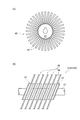
回転ブラシ31は、図6(A)に示すごとき円板状のブラシ体45を備えている。上記ブラシ体45は、回転ブラシ31の回転軸37に取付けるための円板47を備えており、この円板47の外周面には、放射方向に延伸した細長い帯状のサンドペーパーなどのごとき複数のブラシ(研磨材)49が周方向に等間隔に備えられている。そして、図6(B)に示すように、回転ブラシ31の回転軸37に対して、複数のブラシ体45を傾斜した状態に重ねて一体的に取付けることによって、回転ブラシ31が構成してある。したがって、前記回転軸37を回転すると、各ブラシ体45は、回転軸37に対して傾斜した状態を保持して回転されることとなり、かつ前記ブラシ49がワークに作用してワークのバリ取りが行われる。
前記回転ブラシ31A,31Bの径を検出するために、ブラシ径検出部51(図7参照)が備えられている。このブラシ径検出部51は、光学的にブラシ径を検出するものであって、図7に概略的に示すように、前記回転ブラシ31A,31Bの一側方には、例えばレーザ光などの検出光LBを回転ブラシ31A,31Bの回転領域に照射(入射)するレーザダイオード(LD)などのごとき検出光照射部53A,53B,53C,53Dが同一平面内に配置してある。そして、前記回転領域の他側方には、前記回転領域を透過した検出光LBを受光するフォトダイオードなどのごとき複数の受光部55A,55B,55C,55Dが同一平面内に配置してある。
なお、前記各検出光照射部53A~53Dは、前記搬送ベルト15の搬送面15Fから所定距離の位置を透過するように、前記固定フレーム13の所定位置に備えられている。そして、各受光部55A~55Dは、各検出光照射部53A~53Dに対向して固定フレーム13に備えられている。そして、前記各検出光照射部53A~53Dによる検出光LBの照射方向(入射方向)は、前記回転ブラシ31A,31Bの軸方向、すなわち、回転ブラシ31A,31Bにおける回転軸37の長手方向に対して交差する方向であって、かつ前記ブラシ体45における中心軸に対して傾斜した方向である。換言すれば、重ねた状態にある複数のブラシ体45の回転時に描く複数の回転面を横切る方向に検出光LBを照射するように構成してある。
したがって、前述したフレーム移動位置決め装置におけるサーボモータを回転して、回転ブラシ31A,31Bを備えた移動フレーム35をY軸方向に移動すると、図7(B)に示すように、回転ブラシ31A,31Bを、基準位置(原点位置)0から搬送ベルト15に近接する方向へ移動することができる。そして、前記基準位置0からの回転ブラシ31A,31BのY軸方向への移動位置は、前記サーボモータに備えたロータリーエンコーダ等のごとき位置検出部によって検出することができる。
前述のごとく、回転ブラシ31A,31Bを回転しつつ搬送ベルト15に接近する方向へ次第に移動すると、図8の(A)に示すように、回転ブラシ31A,31Bにおける回転領域の外周縁付近が検出光LBを遮断するようになる。この場合、摩耗等によって各ブラシ49の長さは一定でないので、受光部55A~55Dにおいては、図8の(A)に示すように、所定時間T内においてON,OFFを頻繁に繰り返すことになる。
そして、回転ブラシ31A,31Bがさらに搬送ベルト15に近接移動すると、検出光LBは、図8の(B)に示すように、回転領域の外周縁付近からさらに内側の領域を透過することになる。検出光LBが回転領域の内側を透過するようになると、図8の(B)に示すように、所定時間T内における受光部55A~55DのON,OFFの繰り返しが少なくなる。すなわち、ブラシ49によって遮光される時間が次第に長くなる。
その後、回転ブラシ31A,31Bの接近移動がさらに進むと、検出光LBは回転ブラシ31A,31Bの回転領域を透過しなくなる。したがって、NOT回路を介しての受光部55A~55Dの出力は、図8の(C)に示すように、連続してONになる。ところで、前記基準位置0及び検出光LBの照射位置は予め設定した位置であって既知であるから、前述のごとく、受光部55A~55Dが検出光LBを受光しなくなったときの回転ブラシ31A,31BのY軸方向の位置を前記位置検出部によって検出することにより、回転ブラシ31A,31Bの径を演算し求めることができる。
既に理解されるように、図8の(A)の状態は、回転ブラシ31A,31Bの回転時に回転ブラシ31A,31Bの外周面から僅かに突出した状態にある複数のブラシ49の先端付近による検出光LBの遮断を検出している。したがって、図8の(A)の検出状態にあるときの回転ブラシ31A,31Bの径を、回転ブラシ31A,31Bの正確な径に設定することは望ましくない。
換言すれば、図8の(C)に示すように、受光部55A~55Dが検出光LBを受光しなくなったときにおける回転ブラシ31A,31Bの径を正しい径とすることが望ましい。この場合、回転ブラシ31A,31Bにおける外周面は、ワークに対してほぼ均等に作用することになる。したがって、受光部55A~55Dが検出光LBを受光しなくなったときにおける回転ブラシ31A,31Bの径は、作用径と称することも可能である。
また、受光部55A~55Dが検出光LBを受光しなくなったときにおける回転ブラシ31A,31Bの外周面は、ワークのバリ取りを効果的に行うことができる有効な径である。したがって、受光部55A~55Dが検出光LBを受光しなくなったときにおける回転ブラシ31A,31Bの径は、有効径と称することも可能である。
前記バリ取り装置9の動作を制御するために、バリ取り装置9は制御部57(図9参照)を備えている。この制御部57は、例えばコンピュータから構成してあって、CPU59を備えると共に、ワークWの材質に対しての回転ブラシの周速度データ、ワークWの板厚に対応してのバリ取り深さ、すなわち前述のブラシ深さBD1,BD2のデータ、及びワークWの材質、板厚に対応してのワークの送り速度データ等の各データを予め格納した加工条件データベース61を備えている。
さらに、制御部57は各種データを入力する入力部63を備えると共に、前記各受光部55A~55Dが接続してある。そして、前記各検出光照射部53A~55Dから各回転ブラシ31A,31Bの回転領域に照射された検出光LBが、各受光部55A~55Dによって受光されなくなったときにおける各回転ブラシ31A,31Bの基準位置0からの移動位置のデータを格納する位置記憶メモリ65A~65Dが備えられている。また、制御部57には、各種の演算を行う演算部67が備えられている。したがって、各回転ブラシ31A,31Bの径(作用径)は、前記各位置記憶メモリ65A~65Dに格納された移動位置のデータに基づいて、演算部67によって演算されることになる。そして、その演算結果は、ブラシ径メモリ69に格納される。
さらに、前記制御部57には、前記搬送ベルト15を駆動する前記搬送ベルト用モータ29の回転を制御するモータドライバ71Aが接続してあると共に、前記搬送ベルト15に備えた複数の吸着孔25に吸引作用を生じさせる吸引ブロワを駆動するモータドライバ(図示省略)が接続してある。また、前記制御部57には、前記回転ブラシ31A,31Bを回転するための前記ブラシ用モータ43の回転を制御するモータドライバ71Bが接続してある。
また、前記制御部57には、フレーム移動用モータ73の回転を制御するモータドライバ71Cが接続してある。前記フレーム移動用モータ73は、前記回転ブラシ31A,31Bを回転自在に支持した前記移動フレーム35をY軸方向に移動位置決めする機能を奏する。換言すれば、前記フレーム移動用モータ73は、前記搬送ベルト15の搬送面15Fに対する回転ブラシ31A,31Bの接近位置を制御する機能を奏する。
前記フレーム移動用モータ73はサーボモータから構成してあって、位置検出部としてのロータリーエンコーダを備えている。したがって、基準位置からの移動フレーム35の移動位置を検出することができる。なお、位置検出部としては、ロータリーエンコーダに限ることなく、移動フレーム35にリニアエンコーダなどのリニアセンサを備えた構成とすることも可能である。
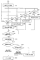
以上のごとき構成において、回転ブラシ31A,31Bの径を検出するには、先ず、図10のステップS1に示すように、予め設定した高速回転でもって回転ブラシ31A,31Bを回転する。回転ブラシ31A,31Bを高速回転すると、回転ブラシ31A,31Bに備えたブラシ49は、遠心力によってほぼ均一に伸びることになる。上述のように、回転ブラシ31A,31Bを高速回転した状態において、フレーム移動用モータ73を回転駆動して、回転ブラシ31A,31Bを基準位置0から搬送ベルト15に接近する方向へ移動する(ステップS2)。
上述のように、回転ブラシ31A,31Bが基準位置0から搬送ベルト15方向へ移動されると、ステップS3において、予め設定した移動量をオーバーしたか否かの判別が行われる。そして、YESの場合には、ステップS4において、センサー検出エラーが報知部75によって報知される。したがって、この場合には、前記検出光照射部53A~53D及び受光部55A~55Dが正常に作動するか否かの検査を行うことになる。
また、前述のように、回転ブラシ31A,31Bが移動されると、ステップS5において、前述したように前記受光部55A~55Dが検出光LBを検出しなくなる動作を行うことになる。したがって、検出光照射部53A~53D及び受光部55A~55Dが正しく動作することが確認される。上述のように動作が確認されると、前記フレーム移動用モータ73が逆回転されて、回転ブラシ31A,31Bは、基準位置0又は、前記検出光LBの位置から予め設定された所定位置に戻されることになる(ステップS6)。
その後、フレーム移動用モータ73を駆動して、基準位置0又は前記所定位置から回転ブラシ31A,31Bを、搬送ベルト15に近接する方向へ移動する(ステップS7)。そして、ステップS8A~S8Dでもって、各検出光照射部53A~53Dと各受光部55A~55Dとの間において、回転ブラシ31A,31Bの回転領域内を検出光LBが透過したか否かを検出する。そして、検出光LBが透過しなくなった位置データを、ステップS9A~S9Dにおいて位置記憶メモリ65A~65Dに格納する。
ステップS10においては、全ての位置検出が完了したか否かの判別を行い、ステップS11において、待機位置としての前記所定位置に移動する(戻る)。その後、ステップS12において、前記各位置記憶メモリ65A~65Dに格納された位置データに基づいて、比較演算部77において偏摩耗の判定を行う。そして、検出位置の差分が予め設定された値より過大なとき、すなわち回転ブラシ31A,31Bの偏摩耗が大きい場合には、ステップS13においてエラー処理を行う。すなわち、例えば回転ブラシ31A,31Bの交換を行う。
前記ステップS12において偏摩耗が小さいと判定したときには、ステップS14において、前記演算部67によって演算した回転ブラシ31A,31Bの最小径と、予め設定した使用限界径とを比較して、使用限界か否かの判別が行われる。そして、使用限界と判別された場合には、ステップS13においてエラー処理が行われる。前記ステップS14において使用可能と判別されると、ステップS15においてバリ取り加工が開始される。
すなわち、加工プログラムメモリ79から必要な加工プログラムが選択されると共に、入力部63から入力されたワークの材質、板厚に対応して加工条件データベース61から回転ブラシ31A,31Bの周速度データ、バリ取り深さBD1,BD2のデータ、及びワークの送り速度データが加工条件メモリ81に格納される。
そして、前記加工条件メモリ81に格納されたワークの送り速度になるように、搬送ベルト用モータ29の回転が制御される。また、回転ブラシ31A,31Bの検出した最小径に基づいて、または、演算部67によって演算された回転ブラシ31A,31Bの平均径に基づいて、回転ブラシ31A,31Bの周速度が前記加工条件メモリ81に格納された回転ブラシ31A,31Bの周速度データに一致するように、ブラシ用モータ43の回転が制御される。さらに、ワークWに対するバリ取り深さが、加工条件メモリ81に格納されたバリ取り深さデータと一致するように、フレーム移動用モータ73によって、搬送ベルト15の搬送面15Fに対する回転ブラシ31A,31Bの近接位置が制御される。
したがって、搬送ベルト15の垂直な搬送面15FにワークWを垂直に吸着して搬送し、かつ回転ブラシ31A,31Bを作用してワークWのバリ取りを行うとき、ワークWの板厚、材質に対応しての回転ブラシ31A,31Bのバリ取り深さ、回転速度(回転ブラシ31A,31Bの周速度)及びワークWの搬送速度が適正に制御されることとなる。したがって、ワークのバリ取りを良好に行い得る。
以上のごとき説明より理解されるように、本実施形態によれば、ワークは、搬送ベルトにおける垂直な搬送面に吸着されて搬送される。したがって、板状のワークを垂直状態に保持して加工を行うと共にワークの搬送を行う板材加工システムに容易に適用することができる。
Claims (5)
- 板状のワークを垂直状態に吸着して搬送する搬送ベルトであって、前記ワークを吸着するための複数の吸着孔が垂直な搬送面に設けられたものと、
前記搬送ベルトに対して接近離反する方向へ移動自在に設けられた、前記ワークのバリ取りを行う回転ブラシと、
からなるバリ取り装置。 - 前記吸着孔は、前記搬送面の下部側よりも上部側に密に設けられている、請求項1に記載のバリ取り装置。
- 前記搬送ベルトの下側に設けられた、当該搬送ベルトの下端縁を案内するベルトガイドからさらになる、請求項1又は2に記載のバリ取り装置。
- 前記回転ブラシの作用径を検出するために、前記回転ブラシにおける回転領域の一側方で検出光を照射する検出光照射部と、前記回転領域の他側方で前記回転領域を透過した検出光を受光する受光部からさらになる、請求項1,2又は3に記載のバリ取り装置。
- 板状のワークを垂直状態に保持してレーザ加工を行うレーザ加工機と、
前記レーザ加工機によってレーザ加工された加工ワークを垂直状態に保持して曲げ加工を行う曲げ加工装置と、
前記レーザ加工機から前記曲げ加工装置へ加工ワークを垂直状態に保持して搬送するワーク搬送装置と、
前記レーザ加工機と前記ワーク搬送装置との間、又は前記ワーク搬送装置と前記曲げ加工装置との間に設けられた、加工ワークを垂直状態に保持してバリ取りを行うバリ取り装置と、
からなる板材加工システム。
Applications Claiming Priority (2)
| Application Number | Priority Date | Filing Date | Title |
|---|---|---|---|
| JP2015-149600 | 2015-07-29 | ||
| JP2015149600A JP6055877B1 (ja) | 2015-07-29 | 2015-07-29 | バリ取り装置及び板材加工システム |
Publications (1)
| Publication Number | Publication Date |
|---|---|
| WO2017018104A1 true WO2017018104A1 (ja) | 2017-02-02 |
Family
ID=57582294
Family Applications (1)
| Application Number | Title | Priority Date | Filing Date |
|---|---|---|---|
| PCT/JP2016/068546 Ceased WO2017018104A1 (ja) | 2015-07-29 | 2016-06-22 | ワークを垂直状態に保持するバリ取り装置及び板材加工システム |
Country Status (2)
| Country | Link |
|---|---|
| JP (1) | JP6055877B1 (ja) |
| WO (1) | WO2017018104A1 (ja) |
Cited By (1)
| Publication number | Priority date | Publication date | Assignee | Title |
|---|---|---|---|---|
| CN108422293A (zh) * | 2018-03-30 | 2018-08-21 | 重庆市永川区华益机械铸造有限责任公司 | 一种铸件加工装置 |
Citations (5)
| Publication number | Priority date | Publication date | Assignee | Title |
|---|---|---|---|---|
| JPH03107447U (ja) * | 1990-02-20 | 1991-11-06 | ||
| JP2000210821A (ja) * | 1999-01-25 | 2000-08-02 | Matsushita Refrig Co Ltd | 板状部品の製造方法 |
| JP2001030028A (ja) * | 1999-05-18 | 2001-02-06 | Amada Co Ltd | 板材加工機およびこの板材加工機を用いた加工方法並びに製品集積方法 |
| JP2001047335A (ja) * | 1999-08-09 | 2001-02-20 | Matsushita Electric Ind Co Ltd | ワーク保持方法およびワーク保持装置 |
| JP2011067919A (ja) * | 2009-09-28 | 2011-04-07 | Fuji Heavy Ind Ltd | 加工バリ取り装置 |
-
2015
- 2015-07-29 JP JP2015149600A patent/JP6055877B1/ja active Active
-
2016
- 2016-06-22 WO PCT/JP2016/068546 patent/WO2017018104A1/ja not_active Ceased
Patent Citations (5)
| Publication number | Priority date | Publication date | Assignee | Title |
|---|---|---|---|---|
| JPH03107447U (ja) * | 1990-02-20 | 1991-11-06 | ||
| JP2000210821A (ja) * | 1999-01-25 | 2000-08-02 | Matsushita Refrig Co Ltd | 板状部品の製造方法 |
| JP2001030028A (ja) * | 1999-05-18 | 2001-02-06 | Amada Co Ltd | 板材加工機およびこの板材加工機を用いた加工方法並びに製品集積方法 |
| JP2001047335A (ja) * | 1999-08-09 | 2001-02-20 | Matsushita Electric Ind Co Ltd | ワーク保持方法およびワーク保持装置 |
| JP2011067919A (ja) * | 2009-09-28 | 2011-04-07 | Fuji Heavy Ind Ltd | 加工バリ取り装置 |
Cited By (1)
| Publication number | Priority date | Publication date | Assignee | Title |
|---|---|---|---|---|
| CN108422293A (zh) * | 2018-03-30 | 2018-08-21 | 重庆市永川区华益机械铸造有限责任公司 | 一种铸件加工装置 |
Also Published As
| Publication number | Publication date |
|---|---|
| JP2017030062A (ja) | 2017-02-09 |
| JP6055877B1 (ja) | 2016-12-27 |
Similar Documents
| Publication | Publication Date | Title |
|---|---|---|
| JP6378418B2 (ja) | 工作物を回転させるための回転ユニットを備える装置、及び加工装置 | |
| JP5596248B1 (ja) | 加工装置及びバリ取り装置 | |
| JP6126657B2 (ja) | バリ取り方法及び装置 | |
| JP6180120B2 (ja) | 拡張装置および拡張方法 | |
| CN110337413B (zh) | 托盘输送装置及托盘输送方法 | |
| CN108527678B (zh) | 被加工物的切削方法 | |
| CN108857086B (zh) | 激光加工方法 | |
| JP2013146831A (ja) | 切削装置 | |
| JP2014172131A (ja) | 研削装置 | |
| CN106346131A (zh) | 激光加工装置 | |
| CN113305445A (zh) | 激光加工装置 | |
| JP6226722B2 (ja) | 高さ位置検出方法 | |
| JP6055877B1 (ja) | バリ取り装置及び板材加工システム | |
| JP5149072B2 (ja) | 切削装置 | |
| KR20210039943A (ko) | 판형 가공물의 연삭 방법 | |
| TW201943525A (zh) | 用於加工工件之邊緣的機器和方法 | |
| JP6926828B2 (ja) | バリ取り装置 | |
| CN113305446A (zh) | 激光加工装置 | |
| JP2005202162A (ja) | レンズストック装置及びこれを有するレンズ加工システム | |
| JP6829048B2 (ja) | ラミネータ及びラミネート方法 | |
| JP6422338B2 (ja) | 加工装置 | |
| JP2000033434A (ja) | バリ取り機 | |
| JP7790268B2 (ja) | 研磨装置 | |
| JP4554228B2 (ja) | ガイドレールの加工装置 | |
| JP6905419B2 (ja) | 切削方法 |
Legal Events
| Date | Code | Title | Description |
|---|---|---|---|
| 121 | Ep: the epo has been informed by wipo that ep was designated in this application |
Ref document number: 16830209 Country of ref document: EP Kind code of ref document: A1 |
|
| NENP | Non-entry into the national phase |
Ref country code: DE |
|
| 122 | Ep: pct application non-entry in european phase |
Ref document number: 16830209 Country of ref document: EP Kind code of ref document: A1 |