WO2017018098A1 - 摺動部材および斜板式コンプレッサ - Google Patents
摺動部材および斜板式コンプレッサ Download PDFInfo
- Publication number
- WO2017018098A1 WO2017018098A1 PCT/JP2016/068368 JP2016068368W WO2017018098A1 WO 2017018098 A1 WO2017018098 A1 WO 2017018098A1 JP 2016068368 W JP2016068368 W JP 2016068368W WO 2017018098 A1 WO2017018098 A1 WO 2017018098A1
- Authority
- WO
- WIPO (PCT)
- Prior art keywords
- coating layer
- solid lubricant
- swash plate
- sliding member
- binder resin
- Prior art date
- Legal status (The legal status is an assumption and is not a legal conclusion. Google has not performed a legal analysis and makes no representation as to the accuracy of the status listed.)
- Ceased
Links
Images



Classifications
-
- F—MECHANICAL ENGINEERING; LIGHTING; HEATING; WEAPONS; BLASTING
- F04—POSITIVE - DISPLACEMENT MACHINES FOR LIQUIDS; PUMPS FOR LIQUIDS OR ELASTIC FLUIDS
- F04B—POSITIVE-DISPLACEMENT MACHINES FOR LIQUIDS; PUMPS
- F04B27/00—Multi-cylinder pumps specially adapted for elastic fluids and characterised by number or arrangement of cylinders
- F04B27/08—Multi-cylinder pumps specially adapted for elastic fluids and characterised by number or arrangement of cylinders having cylinders coaxial with, or parallel or inclined to, main shaft axis
- F04B27/0804—Multi-cylinder pumps specially adapted for elastic fluids and characterised by number or arrangement of cylinders having cylinders coaxial with, or parallel or inclined to, main shaft axis having rotary cylinder block
- F04B27/0821—Multi-cylinder pumps specially adapted for elastic fluids and characterised by number or arrangement of cylinders having cylinders coaxial with, or parallel or inclined to, main shaft axis having rotary cylinder block component parts, details, e.g. valves, sealings, lubrication
- F04B27/086—Multi-cylinder pumps specially adapted for elastic fluids and characterised by number or arrangement of cylinders having cylinders coaxial with, or parallel or inclined to, main shaft axis having rotary cylinder block component parts, details, e.g. valves, sealings, lubrication swash plate
-
- C—CHEMISTRY; METALLURGY
- C09—DYES; PAINTS; POLISHES; NATURAL RESINS; ADHESIVES; COMPOSITIONS NOT OTHERWISE PROVIDED FOR; APPLICATIONS OF MATERIALS NOT OTHERWISE PROVIDED FOR
- C09D—COATING COMPOSITIONS, e.g. PAINTS, VARNISHES OR LACQUERS; FILLING PASTES; CHEMICAL PAINT OR INK REMOVERS; INKS; CORRECTING FLUIDS; WOODSTAINS; PASTES OR SOLIDS FOR COLOURING OR PRINTING; USE OF MATERIALS THEREFOR
- C09D201/00—Coating compositions based on unspecified macromolecular compounds
-
- C—CHEMISTRY; METALLURGY
- C09—DYES; PAINTS; POLISHES; NATURAL RESINS; ADHESIVES; COMPOSITIONS NOT OTHERWISE PROVIDED FOR; APPLICATIONS OF MATERIALS NOT OTHERWISE PROVIDED FOR
- C09D—COATING COMPOSITIONS, e.g. PAINTS, VARNISHES OR LACQUERS; FILLING PASTES; CHEMICAL PAINT OR INK REMOVERS; INKS; CORRECTING FLUIDS; WOODSTAINS; PASTES OR SOLIDS FOR COLOURING OR PRINTING; USE OF MATERIALS THEREFOR
- C09D7/00—Features of coating compositions, not provided for in group C09D5/00; Processes for incorporating ingredients in coating compositions
- C09D7/40—Additives
- C09D7/60—Additives non-macromolecular
- C09D7/61—Additives non-macromolecular inorganic
-
- C—CHEMISTRY; METALLURGY
- C10—PETROLEUM, GAS OR COKE INDUSTRIES; TECHNICAL GASES CONTAINING CARBON MONOXIDE; FUELS; LUBRICANTS; PEAT
- C10M—LUBRICATING COMPOSITIONS; USE OF CHEMICAL SUBSTANCES EITHER ALONE OR AS LUBRICATING INGREDIENTS IN A LUBRICATING COMPOSITION
- C10M169/00—Lubricating compositions characterised by containing as components a mixture of at least two types of ingredient selected from base-materials, thickeners or additives, covered by the preceding groups, each of these compounds being essential
- C10M169/04—Mixtures of base-materials and additives
-
- F—MECHANICAL ENGINEERING; LIGHTING; HEATING; WEAPONS; BLASTING
- F04—POSITIVE - DISPLACEMENT MACHINES FOR LIQUIDS; PUMPS FOR LIQUIDS OR ELASTIC FLUIDS
- F04B—POSITIVE-DISPLACEMENT MACHINES FOR LIQUIDS; PUMPS
- F04B27/00—Multi-cylinder pumps specially adapted for elastic fluids and characterised by number or arrangement of cylinders
- F04B27/08—Multi-cylinder pumps specially adapted for elastic fluids and characterised by number or arrangement of cylinders having cylinders coaxial with, or parallel or inclined to, main shaft axis
-
- F—MECHANICAL ENGINEERING; LIGHTING; HEATING; WEAPONS; BLASTING
- F04—POSITIVE - DISPLACEMENT MACHINES FOR LIQUIDS; PUMPS FOR LIQUIDS OR ELASTIC FLUIDS
- F04B—POSITIVE-DISPLACEMENT MACHINES FOR LIQUIDS; PUMPS
- F04B27/00—Multi-cylinder pumps specially adapted for elastic fluids and characterised by number or arrangement of cylinders
- F04B27/08—Multi-cylinder pumps specially adapted for elastic fluids and characterised by number or arrangement of cylinders having cylinders coaxial with, or parallel or inclined to, main shaft axis
- F04B27/10—Multi-cylinder pumps specially adapted for elastic fluids and characterised by number or arrangement of cylinders having cylinders coaxial with, or parallel or inclined to, main shaft axis having stationary cylinders
- F04B27/1036—Component parts, details, e.g. sealings, lubrication
- F04B27/109—Lubrication
-
- F—MECHANICAL ENGINEERING; LIGHTING; HEATING; WEAPONS; BLASTING
- F16—ENGINEERING ELEMENTS AND UNITS; GENERAL MEASURES FOR PRODUCING AND MAINTAINING EFFECTIVE FUNCTIONING OF MACHINES OR INSTALLATIONS; THERMAL INSULATION IN GENERAL
- F16C—SHAFTS; FLEXIBLE SHAFTS; ELEMENTS OR CRANKSHAFT MECHANISMS; ROTARY BODIES OTHER THAN GEARING ELEMENTS; BEARINGS
- F16C33/00—Parts of bearings; Special methods for making bearings or parts thereof
- F16C33/02—Parts of sliding-contact bearings
- F16C33/04—Brasses; Bushes; Linings
- F16C33/06—Sliding surface mainly made of metal
- F16C33/10—Construction relative to lubrication
- F16C33/1095—Construction relative to lubrication with solids as lubricant, e.g. dry coatings, powder
-
- F—MECHANICAL ENGINEERING; LIGHTING; HEATING; WEAPONS; BLASTING
- F16—ENGINEERING ELEMENTS AND UNITS; GENERAL MEASURES FOR PRODUCING AND MAINTAINING EFFECTIVE FUNCTIONING OF MACHINES OR INSTALLATIONS; THERMAL INSULATION IN GENERAL
- F16C—SHAFTS; FLEXIBLE SHAFTS; ELEMENTS OR CRANKSHAFT MECHANISMS; ROTARY BODIES OTHER THAN GEARING ELEMENTS; BEARINGS
- F16C33/00—Parts of bearings; Special methods for making bearings or parts thereof
- F16C33/02—Parts of sliding-contact bearings
- F16C33/04—Brasses; Bushes; Linings
- F16C33/06—Sliding surface mainly made of metal
- F16C33/12—Structural composition; Use of special materials or surface treatments, e.g. for rust-proofing
- F16C33/122—Multilayer structures of sleeves, washers or liners
- F16C33/124—Details of overlays
-
- C—CHEMISTRY; METALLURGY
- C08—ORGANIC MACROMOLECULAR COMPOUNDS; THEIR PREPARATION OR CHEMICAL WORKING-UP; COMPOSITIONS BASED THEREON
- C08K—Use of inorganic or non-macromolecular organic substances as compounding ingredients
- C08K3/00—Use of inorganic substances as compounding ingredients
- C08K3/30—Sulfur-, selenium- or tellurium-containing compounds
- C08K2003/3009—Sulfides
-
- C—CHEMISTRY; METALLURGY
- C08—ORGANIC MACROMOLECULAR COMPOUNDS; THEIR PREPARATION OR CHEMICAL WORKING-UP; COMPOSITIONS BASED THEREON
- C08K—Use of inorganic or non-macromolecular organic substances as compounding ingredients
- C08K3/00—Use of inorganic substances as compounding ingredients
- C08K3/38—Boron-containing compounds
- C08K2003/382—Boron-containing compounds and nitrogen
- C08K2003/385—Binary compounds of nitrogen with boron
-
- C—CHEMISTRY; METALLURGY
- C08—ORGANIC MACROMOLECULAR COMPOUNDS; THEIR PREPARATION OR CHEMICAL WORKING-UP; COMPOSITIONS BASED THEREON
- C08K—Use of inorganic or non-macromolecular organic substances as compounding ingredients
- C08K3/00—Use of inorganic substances as compounding ingredients
- C08K3/02—Elements
- C08K3/04—Carbon
-
- C—CHEMISTRY; METALLURGY
- C10—PETROLEUM, GAS OR COKE INDUSTRIES; TECHNICAL GASES CONTAINING CARBON MONOXIDE; FUELS; LUBRICANTS; PEAT
- C10M—LUBRICATING COMPOSITIONS; USE OF CHEMICAL SUBSTANCES EITHER ALONE OR AS LUBRICATING INGREDIENTS IN A LUBRICATING COMPOSITION
- C10M2201/00—Inorganic compounds or elements as ingredients in lubricant compositions
- C10M2201/04—Elements
- C10M2201/041—Carbon; Graphite; Carbon black
-
- C—CHEMISTRY; METALLURGY
- C10—PETROLEUM, GAS OR COKE INDUSTRIES; TECHNICAL GASES CONTAINING CARBON MONOXIDE; FUELS; LUBRICANTS; PEAT
- C10M—LUBRICATING COMPOSITIONS; USE OF CHEMICAL SUBSTANCES EITHER ALONE OR AS LUBRICATING INGREDIENTS IN A LUBRICATING COMPOSITION
- C10M2201/00—Inorganic compounds or elements as ingredients in lubricant compositions
- C10M2201/06—Metal compounds
- C10M2201/061—Carbides; Hydrides; Nitrides
-
- C—CHEMISTRY; METALLURGY
- C10—PETROLEUM, GAS OR COKE INDUSTRIES; TECHNICAL GASES CONTAINING CARBON MONOXIDE; FUELS; LUBRICANTS; PEAT
- C10M—LUBRICATING COMPOSITIONS; USE OF CHEMICAL SUBSTANCES EITHER ALONE OR AS LUBRICATING INGREDIENTS IN A LUBRICATING COMPOSITION
- C10M2201/00—Inorganic compounds or elements as ingredients in lubricant compositions
- C10M2201/06—Metal compounds
- C10M2201/065—Sulfides; Selenides; Tellurides
-
- C—CHEMISTRY; METALLURGY
- C10—PETROLEUM, GAS OR COKE INDUSTRIES; TECHNICAL GASES CONTAINING CARBON MONOXIDE; FUELS; LUBRICANTS; PEAT
- C10M—LUBRICATING COMPOSITIONS; USE OF CHEMICAL SUBSTANCES EITHER ALONE OR AS LUBRICATING INGREDIENTS IN A LUBRICATING COMPOSITION
- C10M2201/00—Inorganic compounds or elements as ingredients in lubricant compositions
- C10M2201/06—Metal compounds
- C10M2201/065—Sulfides; Selenides; Tellurides
- C10M2201/066—Molybdenum sulfide
-
- C—CHEMISTRY; METALLURGY
- C10—PETROLEUM, GAS OR COKE INDUSTRIES; TECHNICAL GASES CONTAINING CARBON MONOXIDE; FUELS; LUBRICANTS; PEAT
- C10M—LUBRICATING COMPOSITIONS; USE OF CHEMICAL SUBSTANCES EITHER ALONE OR AS LUBRICATING INGREDIENTS IN A LUBRICATING COMPOSITION
- C10M2217/00—Organic macromolecular compounds containing nitrogen as ingredients in lubricant compositions
- C10M2217/04—Macromolecular compounds from nitrogen-containing monomers obtained otherwise than by reactions only involving carbon-to-carbon unsaturated bonds
- C10M2217/044—Polyamides
- C10M2217/0443—Polyamides used as base material
-
- C—CHEMISTRY; METALLURGY
- C10—PETROLEUM, GAS OR COKE INDUSTRIES; TECHNICAL GASES CONTAINING CARBON MONOXIDE; FUELS; LUBRICANTS; PEAT
- C10N—INDEXING SCHEME ASSOCIATED WITH SUBCLASS C10M RELATING TO LUBRICATING COMPOSITIONS
- C10N2030/00—Specified physical or chemical properties which is improved by the additive characterising the lubricating composition, e.g. multifunctional additives
- C10N2030/06—Oiliness; Film-strength; Anti-wear; Resistance to extreme pressure
-
- C—CHEMISTRY; METALLURGY
- C10—PETROLEUM, GAS OR COKE INDUSTRIES; TECHNICAL GASES CONTAINING CARBON MONOXIDE; FUELS; LUBRICANTS; PEAT
- C10N—INDEXING SCHEME ASSOCIATED WITH SUBCLASS C10M RELATING TO LUBRICATING COMPOSITIONS
- C10N2040/00—Specified use or application for which the lubricating composition is intended
- C10N2040/30—Refrigerators lubricants or compressors lubricants
-
- C—CHEMISTRY; METALLURGY
- C10—PETROLEUM, GAS OR COKE INDUSTRIES; TECHNICAL GASES CONTAINING CARBON MONOXIDE; FUELS; LUBRICANTS; PEAT
- C10N—INDEXING SCHEME ASSOCIATED WITH SUBCLASS C10M RELATING TO LUBRICATING COMPOSITIONS
- C10N2050/00—Form in which the lubricant is applied to the material being lubricated
- C10N2050/015—Dispersions of solid lubricants
-
- C—CHEMISTRY; METALLURGY
- C10—PETROLEUM, GAS OR COKE INDUSTRIES; TECHNICAL GASES CONTAINING CARBON MONOXIDE; FUELS; LUBRICANTS; PEAT
- C10N—INDEXING SCHEME ASSOCIATED WITH SUBCLASS C10M RELATING TO LUBRICATING COMPOSITIONS
- C10N2050/00—Form in which the lubricant is applied to the material being lubricated
- C10N2050/14—Composite materials or sliding materials in which lubricants are integrally molded
-
- F—MECHANICAL ENGINEERING; LIGHTING; HEATING; WEAPONS; BLASTING
- F05—INDEXING SCHEMES RELATING TO ENGINES OR PUMPS IN VARIOUS SUBCLASSES OF CLASSES F01-F04
- F05C—INDEXING SCHEME RELATING TO MATERIALS, MATERIAL PROPERTIES OR MATERIAL CHARACTERISTICS FOR MACHINES, ENGINES OR PUMPS OTHER THAN NON-POSITIVE-DISPLACEMENT MACHINES OR ENGINES
- F05C2203/00—Non-metallic inorganic materials
- F05C2203/08—Ceramics; Oxides
- F05C2203/0804—Non-oxide ceramics
- F05C2203/083—Nitrides
- F05C2203/0839—Nitrides of boron
-
- F—MECHANICAL ENGINEERING; LIGHTING; HEATING; WEAPONS; BLASTING
- F05—INDEXING SCHEMES RELATING TO ENGINES OR PUMPS IN VARIOUS SUBCLASSES OF CLASSES F01-F04
- F05C—INDEXING SCHEME RELATING TO MATERIALS, MATERIAL PROPERTIES OR MATERIAL CHARACTERISTICS FOR MACHINES, ENGINES OR PUMPS OTHER THAN NON-POSITIVE-DISPLACEMENT MACHINES OR ENGINES
- F05C2203/00—Non-metallic inorganic materials
- F05C2203/08—Ceramics; Oxides
- F05C2203/0804—Non-oxide ceramics
- F05C2203/0856—Sulfides
- F05C2203/086—Sulfides of molybdenum
-
- F—MECHANICAL ENGINEERING; LIGHTING; HEATING; WEAPONS; BLASTING
- F05—INDEXING SCHEMES RELATING TO ENGINES OR PUMPS IN VARIOUS SUBCLASSES OF CLASSES F01-F04
- F05C—INDEXING SCHEME RELATING TO MATERIALS, MATERIAL PROPERTIES OR MATERIAL CHARACTERISTICS FOR MACHINES, ENGINES OR PUMPS OTHER THAN NON-POSITIVE-DISPLACEMENT MACHINES OR ENGINES
- F05C2203/00—Non-metallic inorganic materials
- F05C2203/08—Ceramics; Oxides
- F05C2203/0865—Oxide ceramics
- F05C2203/0882—Carbon, e.g. graphite
-
- F—MECHANICAL ENGINEERING; LIGHTING; HEATING; WEAPONS; BLASTING
- F05—INDEXING SCHEMES RELATING TO ENGINES OR PUMPS IN VARIOUS SUBCLASSES OF CLASSES F01-F04
- F05C—INDEXING SCHEME RELATING TO MATERIALS, MATERIAL PROPERTIES OR MATERIAL CHARACTERISTICS FOR MACHINES, ENGINES OR PUMPS OTHER THAN NON-POSITIVE-DISPLACEMENT MACHINES OR ENGINES
- F05C2225/00—Synthetic polymers, e.g. plastics; Rubber
- F05C2225/06—Polyamides, e.g. NYLON
-
- F—MECHANICAL ENGINEERING; LIGHTING; HEATING; WEAPONS; BLASTING
- F05—INDEXING SCHEMES RELATING TO ENGINES OR PUMPS IN VARIOUS SUBCLASSES OF CLASSES F01-F04
- F05C—INDEXING SCHEME RELATING TO MATERIALS, MATERIAL PROPERTIES OR MATERIAL CHARACTERISTICS FOR MACHINES, ENGINES OR PUMPS OTHER THAN NON-POSITIVE-DISPLACEMENT MACHINES OR ENGINES
- F05C2225/00—Synthetic polymers, e.g. plastics; Rubber
- F05C2225/10—Polyimides, e.g. Aurum
-
- F—MECHANICAL ENGINEERING; LIGHTING; HEATING; WEAPONS; BLASTING
- F05—INDEXING SCHEMES RELATING TO ENGINES OR PUMPS IN VARIOUS SUBCLASSES OF CLASSES F01-F04
- F05C—INDEXING SCHEME RELATING TO MATERIALS, MATERIAL PROPERTIES OR MATERIAL CHARACTERISTICS FOR MACHINES, ENGINES OR PUMPS OTHER THAN NON-POSITIVE-DISPLACEMENT MACHINES OR ENGINES
- F05C2251/00—Material properties
- F05C2251/14—Self lubricating materials; Solid lubricants
-
- F—MECHANICAL ENGINEERING; LIGHTING; HEATING; WEAPONS; BLASTING
- F05—INDEXING SCHEMES RELATING TO ENGINES OR PUMPS IN VARIOUS SUBCLASSES OF CLASSES F01-F04
- F05C—INDEXING SCHEME RELATING TO MATERIALS, MATERIAL PROPERTIES OR MATERIAL CHARACTERISTICS FOR MACHINES, ENGINES OR PUMPS OTHER THAN NON-POSITIVE-DISPLACEMENT MACHINES OR ENGINES
- F05C2253/00—Other material characteristics; Treatment of material
- F05C2253/12—Coating
-
- F—MECHANICAL ENGINEERING; LIGHTING; HEATING; WEAPONS; BLASTING
- F05—INDEXING SCHEMES RELATING TO ENGINES OR PUMPS IN VARIOUS SUBCLASSES OF CLASSES F01-F04
- F05C—INDEXING SCHEME RELATING TO MATERIALS, MATERIAL PROPERTIES OR MATERIAL CHARACTERISTICS FOR MACHINES, ENGINES OR PUMPS OTHER THAN NON-POSITIVE-DISPLACEMENT MACHINES OR ENGINES
- F05C2253/00—Other material characteristics; Treatment of material
- F05C2253/18—Filler
-
- F—MECHANICAL ENGINEERING; LIGHTING; HEATING; WEAPONS; BLASTING
- F05—INDEXING SCHEMES RELATING TO ENGINES OR PUMPS IN VARIOUS SUBCLASSES OF CLASSES F01-F04
- F05C—INDEXING SCHEME RELATING TO MATERIALS, MATERIAL PROPERTIES OR MATERIAL CHARACTERISTICS FOR MACHINES, ENGINES OR PUMPS OTHER THAN NON-POSITIVE-DISPLACEMENT MACHINES OR ENGINES
- F05C2253/00—Other material characteristics; Treatment of material
- F05C2253/20—Resin
-
- F—MECHANICAL ENGINEERING; LIGHTING; HEATING; WEAPONS; BLASTING
- F16—ENGINEERING ELEMENTS AND UNITS; GENERAL MEASURES FOR PRODUCING AND MAINTAINING EFFECTIVE FUNCTIONING OF MACHINES OR INSTALLATIONS; THERMAL INSULATION IN GENERAL
- F16C—SHAFTS; FLEXIBLE SHAFTS; ELEMENTS OR CRANKSHAFT MECHANISMS; ROTARY BODIES OTHER THAN GEARING ELEMENTS; BEARINGS
- F16C2202/00—Solid materials defined by their properties
- F16C2202/50—Lubricating properties
- F16C2202/52—Graphite
-
- F—MECHANICAL ENGINEERING; LIGHTING; HEATING; WEAPONS; BLASTING
- F16—ENGINEERING ELEMENTS AND UNITS; GENERAL MEASURES FOR PRODUCING AND MAINTAINING EFFECTIVE FUNCTIONING OF MACHINES OR INSTALLATIONS; THERMAL INSULATION IN GENERAL
- F16C—SHAFTS; FLEXIBLE SHAFTS; ELEMENTS OR CRANKSHAFT MECHANISMS; ROTARY BODIES OTHER THAN GEARING ELEMENTS; BEARINGS
- F16C2202/00—Solid materials defined by their properties
- F16C2202/50—Lubricating properties
- F16C2202/54—Molybdenum disulfide
-
- F—MECHANICAL ENGINEERING; LIGHTING; HEATING; WEAPONS; BLASTING
- F16—ENGINEERING ELEMENTS AND UNITS; GENERAL MEASURES FOR PRODUCING AND MAINTAINING EFFECTIVE FUNCTIONING OF MACHINES OR INSTALLATIONS; THERMAL INSULATION IN GENERAL
- F16C—SHAFTS; FLEXIBLE SHAFTS; ELEMENTS OR CRANKSHAFT MECHANISMS; ROTARY BODIES OTHER THAN GEARING ELEMENTS; BEARINGS
- F16C2208/00—Plastics; Synthetic resins, e.g. rubbers
- F16C2208/20—Thermoplastic resins
- F16C2208/40—Imides, e.g. polyimide [PI], polyetherimide [PEI]
-
- F—MECHANICAL ENGINEERING; LIGHTING; HEATING; WEAPONS; BLASTING
- F16—ENGINEERING ELEMENTS AND UNITS; GENERAL MEASURES FOR PRODUCING AND MAINTAINING EFFECTIVE FUNCTIONING OF MACHINES OR INSTALLATIONS; THERMAL INSULATION IN GENERAL
- F16C—SHAFTS; FLEXIBLE SHAFTS; ELEMENTS OR CRANKSHAFT MECHANISMS; ROTARY BODIES OTHER THAN GEARING ELEMENTS; BEARINGS
- F16C2208/00—Plastics; Synthetic resins, e.g. rubbers
- F16C2208/20—Thermoplastic resins
- F16C2208/40—Imides, e.g. polyimide [PI], polyetherimide [PEI]
- F16C2208/42—Polyamideimide [PAI]
-
- F—MECHANICAL ENGINEERING; LIGHTING; HEATING; WEAPONS; BLASTING
- F16—ENGINEERING ELEMENTS AND UNITS; GENERAL MEASURES FOR PRODUCING AND MAINTAINING EFFECTIVE FUNCTIONING OF MACHINES OR INSTALLATIONS; THERMAL INSULATION IN GENERAL
- F16C—SHAFTS; FLEXIBLE SHAFTS; ELEMENTS OR CRANKSHAFT MECHANISMS; ROTARY BODIES OTHER THAN GEARING ELEMENTS; BEARINGS
- F16C2208/00—Plastics; Synthetic resins, e.g. rubbers
- F16C2208/20—Thermoplastic resins
- F16C2208/60—Polyamides [PA]
Definitions
- the present invention relates to a sliding member having a resin coating layer in which a solid lubricant is dispersed.
- Patent Document 1 discloses a resin coating layer (resin coating layer) having a thickness of 3 ⁇ m or less and a relative c-axis strength ratio of a solid lubricant of 90% in order to reduce the friction coefficient and improve seizure resistance. ) Is formed.
- the present invention provides a technology that achieves both prevention of wear of the coating layer due to initial familiarity and improvement of seizure resistance.
- the present invention includes a base material and a coating layer having a thickness of 10 ⁇ m or more formed on the base material, and the coating layer is a binder resin and a c-axis orientation dispersed in the binder resin. And a solid lubricant having a property, and a relative c-axis strength ratio of the solid lubricant in the coating layer is 80% or more.
- the binder resin may contain at least one of polyamideimide, polyamide, and polyimide.
- the solid lubricant material may include at least one of MoS 2 , graphite, WS 2 , and h-BN.
- the present invention provides a swash plate compressor using any one of the above sliding members as a swash plate.
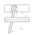
- Sectional schematic diagram which shows the structure of the compressor 1 which concerns on one Embodiment.
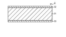
- the figure which illustrates the structure of the swash plate 3 Schematic diagram illustrating the structure of the coating layer 32
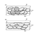
- the schematic diagram which shows the orientation state of the solid lubricant 322 in the coating layer 32 A flowchart illustrating a method for manufacturing the swash plate 3
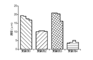
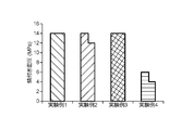
- the figure which shows the measurement result of the film thickness in Experimental Examples 1-4 The figure which shows the measurement result of the orientation rate in Experimental Examples 1-4
- FIG. 1 is a schematic cross-sectional view showing the structure of a compressor 1 according to an embodiment.
- the compressor 1 is a so-called swash plate compressor.
- the compressor 1 has a shaft 2, a swash plate 3, a piston 4, and a shoe 5.
- the shaft 2 is rotatably supported with respect to a housing (not shown).
- the swash plate 3 is fixed obliquely with respect to the rotation axis of the shaft 2.
- the swash plate 3 is an example of the sliding member of the present invention.
- the piston 4 reciprocates in a cylinder bore (not shown) provided in the housing.
- the shoe 5 is provided between the swash plate 3 and the piston 4, and slides with the swash plate 3 and the piston 4, respectively.
- the surface that slides with the swash plate 3 is substantially flat, and the surface that slides with the piston 4 has a dome-like (hemispherical) shape.
- the rotation of the shaft 2 is converted into a reciprocating motion of the piston 4 by the swash plate 3.
- FIG. 2 is a diagram illustrating the structure of the swash plate 3.
- FIG. 2 is a schematic diagram showing a structure in a cross section perpendicular to the sliding surface with the shoe 5.
- the swash plate 3 has a base material 31, a coating layer 32, and a coating layer 33.
- the base material 31 has a disk shape, and is formed of a metal that satisfies required characteristics, for example, an iron-based, copper-based, or aluminum-based alloy. From the viewpoint of preventing adhesion with the shoe 5, the swash plate 3 is preferably formed of a material different from that of the shoe 5.
- FIG. 3 is a schematic view illustrating the structure of the coating layer 32.
- the coating layer 32 is provided to improve the characteristics of the sliding surface of the swash plate 3.
- the coating layer 32 has a binder resin 321 and a solid lubricant 322.
- the coating layer 32 includes, for example, 20 to 70 vol% solid lubricant.
- the balance is a binder resin.
- the binder resin 321 is formed of, for example, a thermosetting resin.
- As the thermosetting resin for example, at least one of polyamide imide (PAI), polyamide (PA), and polyimide (PI) is used.
- Solid lubricant 322 is added to improve lubrication characteristics.
- a crystalline material having c-axis orientation for example, at least one of MoS 2 , graphite (Gr), WS 2 , and h-BN is used.
- a crystalline substance having c-axis orientation refers to a substance having a layered crystal structure, such as a hexagonal system.
- the coating layer 32 may contain hard particles in addition to the solid lubricant 322. As the hard particles, for example, at least one of oxide, nitride, carbide, and sulfide is used.
- the thickness of the coating layer 32 is preferably 10 ⁇ m or more, more preferably 15 ⁇ m or more, and further preferably 20 ⁇ m or more.
- the thickness of the coating layer 32 is less than 5 ⁇ m, the coating layer 32 may be worn and the substrate 31 may be exposed. When the base material 31 is exposed, there arises a problem that the coefficient of friction increases or adheres to the shoe 5. Further, if the coating layer 32 is too thick, the seizure resistance may be lowered. Therefore, the thickness is preferably 50 ⁇ m or less.
- the relative c-axis strength ratio of the solid lubricant 322 in the coating layer 32 is preferably 80% or more, and more preferably 85% or more.
- the relative c-axis intensity ratio refers to the ratio of the diffraction peak intensity from the cleavage plane to the total diffraction peak intensity in X-ray diffraction. More specifically, the relative c-axis intensity ratio is determined from the (002), (004), (100), (101), (102), (103), (105), (110), and (008) planes.
- Is defined as the ratio of the integrated value of diffraction peak intensities from the (002), (004), and (008) planes to the integrated value of diffraction peak intensities. Although diffraction peaks from other than the above nine crystal planes may appear, they are ignored in calculating the relative c-axis intensity ratio because the peak intensity is weak.
- the state in which the relative c-axis intensity ratio is 80% or more, that is, the state in which the relative c-axis intensity ratio is high means that the crystal orientation of the solid lubricant 322 is aligned in the coating layer 32.
- the relative c-axis intensity ratio is hereinafter referred to as “orientation ratio” in the sense that it indicates the degree of alignment of crystal orientations.
- orientation ratio in the sense that it indicates the degree of alignment of crystal orientations.
- solid lubricants exhibit a low coefficient of friction due to interlayer slip in crystals having a layer structure.
- the fact that the crystal orientations are aligned means that the directions in which interlayer slip occurs are aligned.
- FIG. 4 is a schematic diagram showing the orientation state of the solid lubricant 322 in the coating layer 32.
- FIG. 4A shows a state where the orientation rate is low
- FIG. 4B shows a state where the orientation rate is high.
- the solid lubricant 322 is represented as hexagonal flakes.
- the solid lubricant 322 has a cleaved surface aligned in a direction substantially parallel to the sliding surface.
- the average particle diameter of the solid lubricant 322 is, for example, 1 to 6 ⁇ m.
- the average particle diameter is measured by, for example, a laser diffraction method.
- the coating layer 33 is formed in the same manner as the coating layer 32.
- FIG. 5 is a flowchart illustrating a method for manufacturing the swash plate 3.
- a substrate is prepared.
- the base material is molded into a predetermined shape.
- the base material is molded into a disk shape.
- the surface of the substrate may be roughened.
- a paint for forming a coating layer is prepared.
- the binder resin and the solid lubricant are mixed by a known method. These mixtures are diluted with a diluent. Any diluent may be used. For example, N-methylpyrrolidone (NMP) is used. The blending ratio of the diluent is, for example, 30 to 70% by volume with respect to the solid content.
- NMP N-methylpyrrolidone
- the blending ratio of the diluent is, for example, 30 to 70% by volume with respect to the solid content.
- step S4 paint is applied to the surface of the substrate.
- the paint is applied, for example, by pad printing, roll coating, or spray coating. When the thickness of the paint that can be applied at one time is limited, two or more overcoats may be performed.
- step S5 the coating layer is dried and baked. The surface roughness of the coating layer is preferably 5 ⁇ mRz or less, for example.
- Experimental Example Test pieces of sliding members were prepared under various conditions, and their characteristics were evaluated. More specifically, a plurality of test pieces were produced in each of the four sections of Experimental Examples 1 to 4.
- the material and composition of the coating layer 32 are common. PAI was used as the binder resin, and MoS 2 and graphite were used as the solid lubricant.
- Experimental Examples 1 to 4 the coating method for forming the coating layer and the film thickness of the coating layer are different. More specifically, in Experimental Examples 1, 2, and 4, the coating layer was formed by pad printing, whereas in Experimental Example 3, the coating layer was formed by roll coating. Regarding the film thickness, the film thickness was changed in the range of 3 to 19 ⁇ m for the test piece to which the paint was applied by pad printing.
- These experimental examples 1 to 4 were subjected to a seizure resistance test. The seizure resistance was tested by sliding a swash plate and a shoe under the following conditions. This test condition assumes a lubrication state in the compressor. Further, it was confirmed with the naked eye whether or not the coating layer was worn in the following test. Atmosphere: Refrigerant + Refrigerator oil Rotation speed: 7200 rpm (swash plate rotation) Load: Gradual increase (up to 14 MPa)
- Table 1 shows the characteristics of Experimental Examples 1 to 4, the results of the seizure test, and the abrasion test. In Table 1, the manufacturing cost is also described. * 1: See Fig. 6 for detailed film thickness data. * 2: See Fig. 7 for detailed data on the orientation ratio. * 3: See Fig. 8 for detailed data on seizure surface pressure.
- the manufacturing cost of Experimental Example 3 is lower. This is due to the following reason.
- the roll coat has relatively low accuracy from the viewpoint of flatness and parallelism.
- cutting is performed after firing in order to increase the flatness and the parallelism. Therefore, a thick coating is applied as a margin for processing, which contributes to a decrease in yield.
- Pad printing does not require cutting because sufficient accuracy can be achieved. Therefore, the yield of the paint is good and the machining cost can be reduced because the cutting process can be omitted.
- the sliding member according to the present invention is not limited to that used as the swash plate 3 of the compressor 1.
- the sliding member according to the present invention may be used as a sliding member other than a swash plate compressor, such as a half bearing or a bush.
- the material, composition, film thickness, etc. of the coating layer in the experimental example are merely examples. The present invention is not limited to this.
Landscapes
- Engineering & Computer Science (AREA)
- Chemical & Material Sciences (AREA)
- General Engineering & Computer Science (AREA)
- Mechanical Engineering (AREA)
- Organic Chemistry (AREA)
- Wood Science & Technology (AREA)
- Materials Engineering (AREA)
- Life Sciences & Earth Sciences (AREA)
- Inorganic Chemistry (AREA)
- Oil, Petroleum & Natural Gas (AREA)
- General Chemical & Material Sciences (AREA)
- Chemical Kinetics & Catalysis (AREA)
- Lubricants (AREA)
- Compressors, Vaccum Pumps And Other Relevant Systems (AREA)
- Compressor (AREA)
- Sliding-Contact Bearings (AREA)
- Paints Or Removers (AREA)
Abstract
摺動部材である斜板(3)は、基材(31)と、基材(31)上に形成された、厚さ10μm以上のコーティング層(32)とを有し、コーティング層(321)は、バインダー樹脂(321)と、バインダー樹脂(321)中に分散された、c軸配向性を有する固体潤滑剤(322)とを有し、コーティング層(32)における固体潤滑剤(321)の相対c軸強度比が80%以上である。
Description
本発明は、固体潤滑剤が分散された樹脂コーティング層を有する摺動部材に関する。
固体潤滑剤が分散された樹脂コーティング層を有する摺動部材が知られている。特許文献1には、摩擦係数の低減および耐焼付き性の向上を実現するため、厚さが3μm以下でありかつ固体潤滑剤の相対c軸強度比が90%である樹脂被膜層(樹脂コーティング層)が形成された摺動部材が記載されている。
例えば斜板式コンプレッサの斜板など、相対的に潤滑油の少ない環境で使用される摺動部材においては摩耗が進行しやすく、特許文献1に記載の技術では初期なじみによりコーティング層が摩滅してしまう可能性があった。
これに対し本発明は、初期なじみによるコーティング層の摩滅の防止と耐焼付き性の向上とを両立させる技術を提供する。
本発明は、基材と、前記基材上に形成された、厚さ10μm以上のコーティング層とを有し、前記コーティング層は、バインダー樹脂と、前記バインダー樹脂中に分散された、c軸配向性を有する固体潤滑剤とを有し、前記コーティング層における前記固体潤滑剤の相対c軸強度比が80%以上である摺動部材を提供する。
前記バインダー樹脂が、ポリアミドイミド、ポリアミド、およびポリイミドの少なくとも1種を含んでもよい。
前記固体潤滑剤材が、MoS2、グラファイト、WS2、およびh-BNの少なくとも1種を含んでもよい。
また、本発明は、上記いずれかの摺動部材を斜板として用いた斜板式コンプレッサを提供する。
本発明によれば、初期なじみによるコーティング層の摩滅の防止と耐焼付き性の向上とを両立させることができる。
1…コンプレッサ
2…シャフト
3…斜板
31…基材
32…コーティング層
321…バインダー樹脂
322…固体潤滑剤
33…コーティング層
4…ピストン
5…シュー
2…シャフト
3…斜板
31…基材
32…コーティング層
321…バインダー樹脂
322…固体潤滑剤
33…コーティング層
4…ピストン
5…シュー
1.構造
図1は、一実施形態に係るコンプレッサ1の構造を示す断面模式図である。コンプレッサ1は、いわゆる斜板式コンプレッサである。コンプレッサ1は、シャフト2、斜板3、ピストン4、およびシュー5を有する。シャフト2は、ハウジング(図示略)に対して回転可能に支持されている。斜板3は、シャフト2の回転軸に対して斜めに固定されている。斜板3は、本発明の摺動部材の一例である。ピストン4は、ハウジングに設けられたシリンダボア(図示略)内を往復運動する。シュー5は、斜板3とピストン4との間に設けられており、斜板3およびピストン4とそれぞれ摺動する。シュー5において、斜板3と摺動する面はほぼ平坦であり、ピストン4と摺動する面はドーム状(半球状)の形状を有している。シャフト2の回転は、斜板3によりピストン4の往復運動に変換される。
図1は、一実施形態に係るコンプレッサ1の構造を示す断面模式図である。コンプレッサ1は、いわゆる斜板式コンプレッサである。コンプレッサ1は、シャフト2、斜板3、ピストン4、およびシュー5を有する。シャフト2は、ハウジング(図示略)に対して回転可能に支持されている。斜板3は、シャフト2の回転軸に対して斜めに固定されている。斜板3は、本発明の摺動部材の一例である。ピストン4は、ハウジングに設けられたシリンダボア(図示略)内を往復運動する。シュー5は、斜板3とピストン4との間に設けられており、斜板3およびピストン4とそれぞれ摺動する。シュー5において、斜板3と摺動する面はほぼ平坦であり、ピストン4と摺動する面はドーム状(半球状)の形状を有している。シャフト2の回転は、斜板3によりピストン4の往復運動に変換される。
図2は、斜板3の構造を例示する図である。図2は、シュー5との摺動面に垂直な断面における構造を示す模式図である。斜板3は、基材31、コーティング層32、およびコーティング層33を有する。基材31は、円板形状を有しており、要求される特性を満たす金属、例えば、鉄系、銅系、またはアルミニウム系の合金により形成される。シュー5との凝着を防ぐ観点から、斜板3はシュー5とは異なる材料で形成されることが好ましい。
図3は、コーティング層32の構造を例示する模式図である。コーティング層32は、斜板3の摺動面の特性を改善するために設けられている。コーティング層32は、バインダー樹脂321および固体潤滑剤322を有する。コーティング層32は、例えば、20~70vol%の固体潤滑材を含む。残部はバインダー樹脂である。バインダー樹脂321は、例えば熱硬化性樹脂により形成される。熱硬化性樹脂としては、例えば、ポリアミドイミド(PAI)、ポリアミド(PA)、およびポリイミド(PI)の少なくとも1種が用いられる。固体潤滑剤322は、潤滑特性を改善するために添加される。固体潤滑剤322としては、c軸配向性を有する結晶性物質、例えば、MoS2、グラファイト(Gr)、WS2、およびh-BNの少なくとも1種が用いられる。c軸配向性を有する結晶性物質とは、六方晶系等、層状の結晶構造を有する物質をいう。なお、コーティング層32は、固体潤滑剤322に加え、硬質粒子を含んでいてもよい。硬質粒子としては、例えば、酸化物、窒化物、炭化物、および硫化物の少なくとも1種が用いられる。
コーティング層32の摩滅を防止する観点から、コーティング層32の厚さは10μm以上であることが好ましく、15μm以上であることがより好ましく、20μm以上であることがさらに好ましい。例えば、コーティング層32の厚さが5μm未満であると、コーティング層32が摩耗して基材31が露出してしまう場合がある。基材31が露出すると、摩擦係数が増大したり、シュー5と凝着したりする問題が発生する。また、コーティング層32の膜厚が厚すぎるとかえって耐焼付き性が低下する場合があることから、50μm以下であることが好ましい。
また、耐焼付き性を向上させる観点から、コーティング層32における固体潤滑剤322の相対c軸強度比は80%以上であることが好ましく、85%以上であることがより好ましい。ここで、相対c軸強度比とは、X線回折における全回折ピーク強度に対する、劈開面からの回折ピーク強度の比をいう。より詳細には、相対c軸強度比は、(002)、(004)、(100)、(101)、(102)、(103)、(105)、(110)、および(008)面からの回折ピーク強度の積算値に対する、(002)、(004)、および(008)面からの回折ピーク強度の積算値の比として定義される。上記の9つの結晶面以外からの回折ピークが現れる場合もあるが、ピーク強度が弱いため相対c軸強度比の算出においては無視する。
相対c軸強度比が80%以上である、すなわち相対c軸強度比が高い状態とは、コーティング層32において固体潤滑剤322の結晶方位が揃っている状態を意味する。結晶方位が揃っている度合いを示しているという意味において、相対c軸強度比を以下では「配向率」という。一般に固体潤滑剤は、層構造を有する結晶における層間滑りにより低い摩擦係数を示す。結晶方位が揃っているということは、層間滑りが起こる方向が揃っているということである。
図4は、コーティング層32における固体潤滑剤322の配向状態を示す模式図である。図4(A)は配向率が低い状態を、図4(B)は配向率が高い状態を、それぞれ示している。これらの図では、固体潤滑剤322を六角形の薄片として表している。図4(B)の例では、固体潤滑剤322は、劈開面が摺動面にほぼ平行な方向に揃っている。図4(B)のようにコーティング層32において固体潤滑剤322の配向率が高いと、摩擦係数が減少し、耐焼付き性が向上する。
固体潤滑剤322の平均粒径は、例えば1~6μmである。平均粒径は、例えばレーザー回折法により測定される。
コーティング層33は、コーティング層32と同様に形成される。
2.製造方法
図5は、斜板3の製造方法を例示するフローチャートである。ステップS1において、基材が準備される。ステップS2において、基材が所定の形状に成型される。この例では、基材が円板状に成型される。基材とコーティング層との密着性を高めるため、基材の表面が粗面化されてもよい。
図5は、斜板3の製造方法を例示するフローチャートである。ステップS1において、基材が準備される。ステップS2において、基材が所定の形状に成型される。この例では、基材が円板状に成型される。基材とコーティング層との密着性を高めるため、基材の表面が粗面化されてもよい。
ステップS3において、コーティング層を形成するための塗料が準備される。まず、バインダー樹脂および固体潤滑剤が公知の方法で混合される。これらの混合体は、希釈剤で希釈される。希釈剤としてはどのようなものが用いられてもよいが、例えば、N-メチルピロリドン(NMP)が用いられる。希釈剤の配合比率は、固形分に対して例えば30~70体積%である。
ステップS4において、基材の表面に塗料が塗布される。塗料は、例えば、パッド印刷、ロールコーティング、またはスプレーコーティングにより塗布される。1回で塗布できる塗料の厚さが制限される場合、2回以上の重ね塗りが行われてもよい。ステップS5において、塗布層は乾燥および焼成される。コーティング層の表面粗さは、例えば5μmRz以下であることが好ましい。
3.実験例
種々の条件で摺動部材の試験片を作製し、これらの特性を評価した。より詳細には、実験例1~4の4つの区分において、それぞれ複数の試験片を作製した。実験例1~4において、コーティング層32の材料および組成は共通である。バインダー樹脂としてはPAIを、固体潤滑材としてはMoS2およびグラファイトを用いた。実験例1~4の基材としては、鋳鉄(FCD700)を用いた。
種々の条件で摺動部材の試験片を作製し、これらの特性を評価した。より詳細には、実験例1~4の4つの区分において、それぞれ複数の試験片を作製した。実験例1~4において、コーティング層32の材料および組成は共通である。バインダー樹脂としてはPAIを、固体潤滑材としてはMoS2およびグラファイトを用いた。実験例1~4の基材としては、鋳鉄(FCD700)を用いた。
実験例1~4においては、コーティング層を形成するための塗料の塗布方法およびコーティング層の膜厚が異なっている。より具体的には、実験例1、2、および4は、パッド印刷によりコーティング層が形成されたのに対し、実験例3はロールコーティングによりコーティング層が形成された。膜厚に関しては、パッド印刷で塗料を塗布した試験片については、膜厚を3~19μmの範囲で変化させた。これらの実験例1~4に対して、耐焼付き性の試験を行った。耐焼付き性は、以下の条件で斜板とシューとを摺動させて試験した。この試験条件は、コンプレッサ内の潤滑状態を想定したものである。また、以下の試験においてコーティング層の摩滅が発生したか否か、肉眼で確認した。
雰囲気:冷媒+冷凍機油
回転数:7200rpm(斜板回転)
荷重:漸増(最大14MPa)
雰囲気:冷媒+冷凍機油
回転数:7200rpm(斜板回転)
荷重:漸増(最大14MPa)
表1は、実験例1~4の特性、焼付き試験および摩滅試験の結果を示す。なお表1においては製造コストについても記載している。

*1:膜厚の詳細なデータは図6参照。
*2:配向率の詳細なデータは図7参照。
*3:焼付き面圧の詳細なデータは図8参照。
*1:膜厚の詳細なデータは図6参照。
*2:配向率の詳細なデータは図7参照。
*3:焼付き面圧の詳細なデータは図8参照。
コーティング層をパッド印刷で塗布した試料(実験例1、2、および4)とロールコーティングで塗布した試料(実験例3)とを対比すると、パッド印刷で塗布した試料の方が配向率が高い傾向が見られた。パッドコートでは薄い膜を積層して所望の膜厚を得ている。1層あたりの膜厚は添加剤のサイズと同等程度になり、添加剤を押しつける効果が得ら、高い配向率が得られる。一方で、ロールコーティングでは1回で所望の厚さの膜を塗布している。そのため、添加剤のサイズを基準とすると膜厚は(パッドコートよりも)厚くなり、添加剤を押しつける効果が弱くなり、相対的に低い配向率が得られる。
実験例1~3と実験例4とを対比すると、膜厚が薄い試験片(実験例4)は、膜厚が厚い試験片(実験例1~3)と比較して耐焼付き性が低いという結果が得られた。なお、試験装置の制約から実験例1と実験例3に対しては耐焼付き性の差を評価することができなかったが、特許第4827680号の明細書に記載されているように、配向率(相対c軸強度)の上昇に伴い焼付き面圧が上昇すると考えられる。
実験例1と実験例3とを比較すると、実験例3の方が製造コストが低い。これは以下の理由による。ロールコートでは、平面度および平行度という観点から、相対的に精度が低い。実験例3では、平面度および平行度を高くするため、焼成後に切削加工を行っている。そのため、加工しろとして塗料を厚めに塗っており、歩留まり低下の一因となっている。パッド印刷では十分な精度が出せるため切削加工が不要である。したがって、塗料の歩留まりがよく、また切削加工を省略できるので加工コストも低い。
なお、本発明に係る摺動部材は、コンプレッサ1の斜板3として用いられるものに限定されない。本発明に係る摺動部材は、半割軸受やブシュなど、斜板式コンプレッサ以外の摺動部材として用いられてもよい。実験例におけるコーティング層の材料、組成、膜厚等はあくまで例示である。本発明はこれに限定されるものではない。
Claims (4)
- 基材と、
前記基材上に形成された、厚さ10μm以上のコーティング層と
を有し、
前記コーティング層は、
バインダー樹脂と、
前記バインダー樹脂中に分散された、c軸配向性を有する固体潤滑剤と
を有し、
前記コーティング層における前記固体潤滑剤の相対c軸強度比が80%以上である
摺動部材。 - 前記バインダー樹脂が、ポリアミドイミド、ポリアミド、およびポリイミドの少なくとも1種を含む
ことを特徴とする請求項1に記載の摺動部材。 - 前記固体潤滑剤が、MoS2、グラファイト、WS2、およびh-BNの少なくとも1種を含む
ことを特徴とする請求項1または2に記載の摺動部材。 - 請求項1ないし3のいずれか一項に記載の摺動部材を斜板として用いた斜板式コンプレッサ。
Priority Applications (1)
| Application Number | Priority Date | Filing Date | Title |
|---|---|---|---|
| US15/747,638 US20180216608A1 (en) | 2015-07-29 | 2016-06-21 | Sliding member and swash plate compressor |
Applications Claiming Priority (2)
| Application Number | Priority Date | Filing Date | Title |
|---|---|---|---|
| JP2015-149264 | 2015-07-29 | ||
| JP2015149264A JP2017031987A (ja) | 2015-07-29 | 2015-07-29 | 摺動部材および斜板式コンプレッサ |
Publications (1)
| Publication Number | Publication Date |
|---|---|
| WO2017018098A1 true WO2017018098A1 (ja) | 2017-02-02 |
Family
ID=57885551
Family Applications (1)
| Application Number | Title | Priority Date | Filing Date |
|---|---|---|---|
| PCT/JP2016/068368 Ceased WO2017018098A1 (ja) | 2015-07-29 | 2016-06-21 | 摺動部材および斜板式コンプレッサ |
Country Status (3)
| Country | Link |
|---|---|
| US (1) | US20180216608A1 (ja) |
| JP (1) | JP2017031987A (ja) |
| WO (1) | WO2017018098A1 (ja) |
Families Citing this family (2)
| Publication number | Priority date | Publication date | Assignee | Title |
|---|---|---|---|---|
| JP7092636B2 (ja) * | 2018-10-22 | 2022-06-28 | 大同メタル工業株式会社 | 摺動部材及びこれを用いる軸受装置 |
| JP7171409B2 (ja) * | 2018-12-17 | 2022-11-15 | 大豊工業株式会社 | 摺動部材 |
Citations (2)
| Publication number | Priority date | Publication date | Assignee | Title |
|---|---|---|---|---|
| JP2004323594A (ja) * | 2003-04-22 | 2004-11-18 | Toyota Industries Corp | 塗料組成物及び摺動部品 |
| JP2008095725A (ja) * | 2006-10-06 | 2008-04-24 | Taiho Kogyo Co Ltd | 摺動部材 |
Family Cites Families (1)
| Publication number | Priority date | Publication date | Assignee | Title |
|---|---|---|---|---|
| JP2004010707A (ja) * | 2002-06-05 | 2004-01-15 | Taiho Kogyo Co Ltd | 摺動用被覆組成物及び摺動部材 |
-
2015
- 2015-07-29 JP JP2015149264A patent/JP2017031987A/ja active Pending
-
2016
- 2016-06-21 WO PCT/JP2016/068368 patent/WO2017018098A1/ja not_active Ceased
- 2016-06-21 US US15/747,638 patent/US20180216608A1/en not_active Abandoned
Patent Citations (2)
| Publication number | Priority date | Publication date | Assignee | Title |
|---|---|---|---|---|
| JP2004323594A (ja) * | 2003-04-22 | 2004-11-18 | Toyota Industries Corp | 塗料組成物及び摺動部品 |
| JP2008095725A (ja) * | 2006-10-06 | 2008-04-24 | Taiho Kogyo Co Ltd | 摺動部材 |
Also Published As
| Publication number | Publication date |
|---|---|
| JP2017031987A (ja) | 2017-02-09 |
| US20180216608A1 (en) | 2018-08-02 |
Similar Documents
| Publication | Publication Date | Title |
|---|---|---|
| EP2264316B1 (en) | Swash plate and method of manufacturing same | |
| US9029302B2 (en) | Sliding member | |
| WO2014181562A1 (ja) | 摺動部材 | |
| JPH01261514A (ja) | 摺動材料 | |
| JP5321943B2 (ja) | 斜板式コンプレッサの斜板および斜板式コンプレッサ | |
| WO2017018098A1 (ja) | 摺動部材および斜板式コンプレッサ | |
| JP5820760B2 (ja) | すべり軸受とその製造方法 | |
| EP3543295B1 (en) | Resin composition and sliding member | |
| EP3543322B1 (en) | Sliding member | |
| WO2018216675A1 (ja) | 摺動部材用樹脂材料及び摺動部材 | |
| JPWO2014103067A1 (ja) | 斜板式圧縮機 | |
| JP6468991B2 (ja) | 摺動部材および斜板式コンプレッサ | |
| JP5816121B2 (ja) | すべり軸受とその製造方法 | |
| JP2018035838A (ja) | スラストワッシャ | |
| WO2017094810A1 (ja) | 摺動部材および斜板式コンプレッサ | |
| JP2009062935A (ja) | 斜板式コンプレッサーの斜板用摺動材組成物および摺動材 | |
| RU2485365C1 (ru) | Подшипник скольжения с наноструктурным металлокерамоматричным антифрикционным покрытием | |
| US20220106982A1 (en) | Sliding member |
Legal Events
| Date | Code | Title | Description |
|---|---|---|---|
| 121 | Ep: the epo has been informed by wipo that ep was designated in this application |
Ref document number: 16830203 Country of ref document: EP Kind code of ref document: A1 |
|
| WWE | Wipo information: entry into national phase |
Ref document number: 15747638 Country of ref document: US |
|
| NENP | Non-entry into the national phase |
Ref country code: DE |
|
| 122 | Ep: pct application non-entry in european phase |
Ref document number: 16830203 Country of ref document: EP Kind code of ref document: A1 |