WO2017014182A1 - 太陽電池の取付構造 - Google Patents
太陽電池の取付構造 Download PDFInfo
- Publication number
- WO2017014182A1 WO2017014182A1 PCT/JP2016/070989 JP2016070989W WO2017014182A1 WO 2017014182 A1 WO2017014182 A1 WO 2017014182A1 JP 2016070989 W JP2016070989 W JP 2016070989W WO 2017014182 A1 WO2017014182 A1 WO 2017014182A1
- Authority
- WO
- WIPO (PCT)
- Prior art keywords
- electrode terminal
- solar cell
- conductive material
- solar cells
- electrode
- Prior art date
- Legal status (The legal status is an assumption and is not a legal conclusion. Google has not performed a legal analysis and makes no representation as to the accuracy of the status listed.)
- Ceased
Links
Images



Classifications
-
- H—ELECTRICITY
- H10—SEMICONDUCTOR DEVICES; ELECTRIC SOLID-STATE DEVICES NOT OTHERWISE PROVIDED FOR
- H10F—INORGANIC SEMICONDUCTOR DEVICES SENSITIVE TO INFRARED RADIATION, LIGHT, ELECTROMAGNETIC RADIATION OF SHORTER WAVELENGTH OR CORPUSCULAR RADIATION
- H10F19/00—Integrated devices, or assemblies of multiple devices, comprising at least one photovoltaic cell covered by group H10F10/00, e.g. photovoltaic modules
- H10F19/90—Structures for connecting between photovoltaic cells, e.g. interconnections or insulating spacers
- H10F19/902—Structures for connecting between photovoltaic cells, e.g. interconnections or insulating spacers for series or parallel connection of photovoltaic cells
- H10F19/904—Structures for connecting between photovoltaic cells, e.g. interconnections or insulating spacers for series or parallel connection of photovoltaic cells characterised by the shapes of the structures
-
- H—ELECTRICITY
- H02—GENERATION; CONVERSION OR DISTRIBUTION OF ELECTRIC POWER
- H02S—GENERATION OF ELECTRIC POWER BY CONVERSION OF INFRARED RADIATION, VISIBLE LIGHT OR ULTRAVIOLET LIGHT, e.g. USING PHOTOVOLTAIC [PV] MODULES
- H02S40/00—Components or accessories in combination with PV modules, not provided for in groups H02S10/00 - H02S30/00
- H02S40/30—Electrical components
- H02S40/36—Electrical components characterised by special electrical interconnection means between two or more PV modules, e.g. electrical module-to-module connection
-
- H—ELECTRICITY
- H10—SEMICONDUCTOR DEVICES; ELECTRIC SOLID-STATE DEVICES NOT OTHERWISE PROVIDED FOR
- H10F—INORGANIC SEMICONDUCTOR DEVICES SENSITIVE TO INFRARED RADIATION, LIGHT, ELECTROMAGNETIC RADIATION OF SHORTER WAVELENGTH OR CORPUSCULAR RADIATION
- H10F19/00—Integrated devices, or assemblies of multiple devices, comprising at least one photovoltaic cell covered by group H10F10/00, e.g. photovoltaic modules
- H10F19/90—Structures for connecting between photovoltaic cells, e.g. interconnections or insulating spacers
-
- H—ELECTRICITY
- H10—SEMICONDUCTOR DEVICES; ELECTRIC SOLID-STATE DEVICES NOT OTHERWISE PROVIDED FOR
- H10F—INORGANIC SEMICONDUCTOR DEVICES SENSITIVE TO INFRARED RADIATION, LIGHT, ELECTROMAGNETIC RADIATION OF SHORTER WAVELENGTH OR CORPUSCULAR RADIATION
- H10F77/00—Constructional details of devices covered by this subclass
- H10F77/20—Electrodes
- H10F77/206—Electrodes for devices having potential barriers
- H10F77/211—Electrodes for devices having potential barriers for photovoltaic cells
- H10F77/215—Geometries of grid contacts
-
- Y—GENERAL TAGGING OF NEW TECHNOLOGICAL DEVELOPMENTS; GENERAL TAGGING OF CROSS-SECTIONAL TECHNOLOGIES SPANNING OVER SEVERAL SECTIONS OF THE IPC; TECHNICAL SUBJECTS COVERED BY FORMER USPC CROSS-REFERENCE ART COLLECTIONS [XRACs] AND DIGESTS
- Y02—TECHNOLOGIES OR APPLICATIONS FOR MITIGATION OR ADAPTATION AGAINST CLIMATE CHANGE
- Y02E—REDUCTION OF GREENHOUSE GAS [GHG] EMISSIONS, RELATED TO ENERGY GENERATION, TRANSMISSION OR DISTRIBUTION
- Y02E10/00—Energy generation through renewable energy sources
- Y02E10/50—Photovoltaic [PV] energy
Definitions
- the present invention relates to a solar cell mounting structure.
- This application claims priority based on Japanese Patent Application No. 2015-143505 filed in Japan on July 17, 2015, the contents of which are incorporated herein by reference.
- the fixture of the above-mentioned Patent Document 1 has a problem that the structure is complicated and the fixing of the solar cell is easy to loosen and poor contact is likely to occur. Therefore, the present invention provides a solar cell mounting structure capable of easily and reliably performing electrical connection.
- the solar cell mounting structure of the present invention includes a plurality of solar cells and a fixture having a pair of gripping members that grip the plurality of solar cells, and each solar cell has an end on one side.
- a first electrode terminal provided at a portion and a second electrode terminal provided at an end on the opposite side, wherein the solar cell is arranged in a direction in which the direction between the first electrode terminal and the second electrode terminal is arranged
- the pair of gripping members are arranged in a direction opposite to the fixed portion, and a fixed portion for arranging at least one electrode terminal selected from the first electrode terminal and the second electrode terminal, respectively.
- the plurality of solar cells arranged in one direction are gripped by the pair of gripping members so as to be sandwiched from the direction orthogonal to the one direction, and the plurality of solar cells are electrically connected.
- a second electrode terminal of a solar cell adjacent to the first electrode terminal of one solar cell is gripped from a direction perpendicular to the arrangement direction of the solar cells by a pair of gripping members, and is provided on the pair of gripping members. Electrical connection is made by contacting the conductive material. Therefore, according to the present invention, a plurality of solar cells can be simply and reliably attached to an attachment target and can be electrically connected.
- the plurality of solar cells are arranged so that the first electrode terminals and the second electrode terminals are alternately held by one of the holding members,
- the holding part or the holding part of one of the gripping members extends between the first electrode terminal and the second electrode terminal for each pair of adjacent first electrode terminals and second electrode terminals.
- the conductive material that is electrically conductive is provided, and the other fixed portion or the holding portion has a pair of adjacent first electrodes that are not conductive with the conductive material of the one fixed portion or the holding portion.
- a conductive material extending to the first electrode terminal and the second electrode terminal and electrically conducting is provided for each terminal and the second electrode terminal, and the adjacent solar cells are connected in series.
- a plurality of solar cells can be easily attached and can be simply and reliably connected in series.
- a plurality of the first electrode terminals are held by one holding member of the pair of holding members, and the second electrode terminal is held by the other holding member.
- a plurality of grips, and the fixing part or the pressing part of the one gripping member is provided with a conductive material that electrically connects the adjacent first electrode terminals, and the fixing part of the other gripping member
- the holding portion is provided with a conductive material that electrically connects the adjacent second electrode terminals, and the solar cells are connected in parallel.
- a plurality of solar cells can be easily attached and can be simply and reliably connected in parallel.
- the solar cell adjacent to the first electrode terminal of one solar cell while directing the same electrode of the plurality of solar cells to the same surface side to the pair of gripping members.
- the second electrode terminals of the battery are alternately gripped, and a conductive material is formed on either the fixing portion or the pressing portion, and the fastening member includes the conductive material and a surface on which the conductive material is provided. Electrical connection may be achieved by conducting between the first electrode terminal and the second electrode terminal facing the same surface.
- a plurality of solar cells can be easily attached and simply and reliably connected in series simply by changing the direction of the end of the solar cell and attaching it to the gripping member.
- the fitting of the present invention permits an arrangement when the solar cell can be electrically connected, and does not allow an arrangement when the solar cell cannot be electrically connected. And / or at least one of the engaged portions, and at least the other of the engaged portion and the engaging portion corresponding to the engaging portion and the engaged portion may be formed on the solar cell.
- the present invention can definitely perform the attachment of the solar cell to the fixture.
- the present invention has an effect that it is possible to easily and reliably perform the attachment of the solar cell to an attachment target such as a wall of a building and the electrical connection between the solar cells.
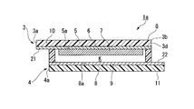
- FIG. 2 is a cross-sectional view schematically showing the solar cell of FIG. 1 that can be applied to the solar cell mounting structure of one embodiment of the present invention, taken along the line P1-P1. It is the figure which decomposed
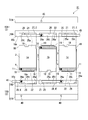
- FIG. 2 is a cross-sectional view taken along the line P2-P2 in FIG. It is the figure which decomposed
- the solar cell mounting structure X1 of the present invention in which the formation of a series connection circuit of solar cells and the mounting of solar cells are extremely easy, simple and reliable, will be described with reference to FIGS.
- the solar cell mounting structure X1 forms a series connection circuit with panel type solar cells 1a-1c, and the solar cells 1a-1c are to be mounted on a wall or roof of a building (not shown).
- an attachment 2 that can be attached to the housing.
- any solar cell 1a-1c may be used as long as it has a plate-like photoelectrode 3 and a counter electrode 4 as shown in FIG. Anything can be applied.
- the solar cell mounting structure X1 will be described by exemplifying the dye-sensitized solar cell (hereinafter simply referred to as “battery”) 1a-1c shown in FIG.
- the photoelectrode 3 and the counter electrode 4 are displayed slightly shifted in the short direction (the same applies to FIGS. 5 and 6 described later).
- the batteries 1a to 1c known ones are used. As shown in FIG. 2, in the battery 1a, the photoelectrode 3 and the counter electrode 4 are bonded around the outer edge G in a state where the internal space K is filled with an electrolyte solution (not shown), and is substantially rectangular in plan view (FIG. 2). 1) formed.
- the batteries 1b and 1c have the same structure as the battery 1a.
- an electrolyte layer may be applied instead of the electrolytic solution.
- the electrolyte layer has a function similar to that of the electrolytic solution, and is in a gel or solid state.
- the electrolyte layer for example, a solution obtained by gelling or solidifying the electrolyte solution by adding a gelling agent or a thickener to the electrolyte solution and removing the solvent as necessary can be applied.
- a gelling agent or a thickener to the electrolyte solution and removing the solvent as necessary.
- a transparent conductive film 6 is formed on the surface 5 a of the transparent substrate 5, a porous semiconductor 7 is further formed, and the semiconductor 7 carries a dye.
- the counter electrode 4 is formed by forming a conductive film 9 on the surface 8 a of the substrate 8.
- An end portion (end portion on one side) 10 extending in the short side direction (the depth direction in FIG. 2) along one side 3a of the photoelectrode 3 protrudes from the end edge 4a of the counter electrode 4, and the transparent conductive film 6 is
- the first electrode terminal 21 is configured by being exposed.
- the first electrode terminal 21 is formed with a notch 18 cut into a rectangle at an intermediate portion in the short direction.
- the notch 18 is formed at a position shifted in the lateral direction with respect to the center in the lateral direction of the photoelectrode 3.
- an end portion (end portion on the opposite side) 11 of the counter electrode 4 extending in the short direction along the opposite side 3b protrudes from the end edge 3d of the photoelectrode 3, and the conductive film 9 is exposed.
- a second electrode terminal 22 is configured.
- the second electrode terminal 22 is formed with a notch 19 in which both ends in the short direction are cut into rectangles.
- the first electrode terminal 21 and the second electrode terminal 22 are formed so as to protrude in opposite directions (that is, in a direction orthogonal to the arrangement direction of the batteries 1a-1c) and to face opposite surfaces.
- the fixture 2 has a plurality of batteries 1a-1c arranged in one direction so that the first electrode terminal 21 and the second electrode terminal 22 form side end portions S1 and S2, and the side end portion A pair of gripping members 15A and 15B for gripping S1 and S2 from a direction orthogonal to one direction are provided.
- “Side end portions S1 and S2” are side end portions of the entire outer shape of the arranged batteries 1a, 1b, and 1c.
- the batteries 1a, 1b, and 1c include the first electrode terminal 21 of each battery 1a-1c such that the first electrode terminal 21 and the second electrode terminal 22 are connected in a straight line to form a pair of side end portions S1 and S1.
- the direction between the second electrode terminals 22 is oriented in a direction perpendicular to the arrangement direction of the batteries 1a-1c.
- the holding member 15A includes a first electrode terminal 21 and a second electrode terminal 22 that are arranged in a straight line and arranged alternately, and a fixed portion 16A that is arranged opposite to the fixed portion 16A. 21 and a presser portion 17A for sandwiching the second electrode terminal 22.
- the gripping member 15B includes a fixed portion 16B in which the first electrode terminals 21 and the second electrode terminals 22 are arranged in a straight line and alternately disposed, and the first electrode terminal 21 and the second electrode terminal that are disposed opposite to the fixed portion 16B.
- Each of the presser portions 17 ⁇ / b> B sandwiches 22.
- the fixing portion 16A is formed in a long rectangular shape using an insulating material such as a synthetic resin material.
- a first fitting recess 25 and a second fitting recess 26 on which the end portions 10 and 11 of the battery 1a-1c are placed are formed on the surface 16s of the fixed portion 16A.
- the first fitting recess 25 and the second fitting recess 26 are alternately formed so as to open to the one end 16a side in the short direction of the fixing portion 16A and in the longitudinal direction of the fixing portion 16A. .
- the first fitting recess 25 is formed to be slightly larger than the end portion 10 in accordance with the outer shape of the end portion 10 in plan view.
- a projection 25 a is formed on the bottom surface 25 t of the first fitting recess 25 to fit the notch 18 when the first electrode terminal 21 is disposed opposite the first fitting recess 25.
- the notch 18 and the protrusion 25a are formed so as to correspond to each other at a position shifted from the center in the short direction of the battery 1a.
- the second fitting recess 26 is formed to be slightly larger than the end portion 11 in accordance with the outer shape of the end portion 11 in plan view. Then, on the bottom surface 26t of the second fitting recess 26, when the second electrode terminal 22 is oriented in the same direction as the bottom surface 26t (that is, when facing the front side of the paper in this figure), the projection fitted into the notch 19 26a is formed. The depths of the first fitting recess 25 and the second fitting recess 26 are formed to be smaller than the thickness dimension of the battery 1a-1c.
- the shapes of the first fitting recess 25 and the end portion 10 are not formed symmetrically with respect to the center line in the short direction, and the first fitting recess 25 and the second fitting recess.
- the locations 26 and the end portions 10 and 11 are not formed with respect to the center line in the longitudinal direction. Therefore, as shown in FIG. 3, the first fitting recess 25 fits the end portion 10 when the end portion 10 is to be disposed with the first electrode terminal 21 facing the bottom surface 25 t.
- the projection 25a does not engage with the notch 18 when the end portion 10 is arranged with the first electrode terminal 21 facing the opposite surface, the projection 25a has the end portion. 10 is prevented.
- the conductive material E continues across the first fitting recess 25 and the second fitting recess 26 corresponding to the first electrode terminal 21 of the battery 1a and the second electrode terminal 22 of the battery 1b.
- no conductive material E is provided between the battery 1b and the battery 1c, and the battery is formed from the surface of the first fitting recess 25 corresponding to the first electrode terminal 21 of the battery 1c.
- a conductive material E is further provided toward the terminal 45 provided at one end on the 1c side.
- a through hole is formed at a position that penetrates the second electrode terminal 22 and the conductive material E as shown in FIG. 30 is formed.
- a tightening member 40 such as a screw can be inserted into the through hole 30.
- a second fitting recess 26, a first fitting recess 25, and a second fitting so that an electrode terminal opposite to the electrode terminal fitted in the fixing portion 16A can be arranged.
- the recess 26 is formed in this order.
- a conductive material E is provided so as to conduct between the terminal 45 formed at the end portion on the side corresponding to the battery 1a and the second fitting recess 26.
- the conductive material E is further continuously straddling the first fitting recess 25 corresponding to the first electrode terminal 21 of the battery 1b and the second fitting recess 26 corresponding to the second electrode terminal 22 of the battery 1c. Is formed.
- the through hole 30 is formed at a position that penetrates the second electrode terminal 22 and the conductive material E. Is formed.
- a tightening member 40 such as a screw can be inserted into the through hole 30.
- the conductive material E is provided in the fixing portion 16A and the fixing portion 16B by shifting the combination of the first fitting recess 25 and the second fitting recess 26 one by one.
- the conductive material E is formed in a long band shape, and the fixed portion 16A forms a first conductive portion 27 and the fixed portion 16B forms a second conductive portion 28.
- the conductive material E is formed of a conductive tape or a conductive paste having a predetermined thickness (for example, about 10 ⁇ m to 500 ⁇ m).
- the holding parts 17A and 17B are formed with the same outer shape as the fixing part 16A using an insulating material such as a synthetic resin material.
- the tightening member 40 has a slightly larger cross-sectional area than the through hole 30, and when inserted into the through hole 30, the second electrode terminal 22, the first conductive portion 27, the second electrode terminal 22, and the second electrode It comes into contact with the conductive portion 28. Further, the tightening member 40 is capable of tightening so that the fixing portion 16A (16B) and the presser portion 17A (17B) are in close contact with each other, and has conductivity.
- the second electrode terminal 22 and the conductive material E are electrically connected by the tightening member 40.
- the notches 18 and 19 and the first fitting recess 25 and the second fitting recess 26 allow fitting (arrangement) only when the batteries 1a to 1c are in an orientation in which they can be electrically connected to each other. In the case of other orientations, engaging portions or engaged portions that are engaged with each other and are not allowed to be arranged are configured.
- the fixing portions 16A and 16B are arranged with an interval at which the batteries 1a to 1c can be fitted to the fixing portion 16A and the fixing portion 16B.
- the end portion 10 is fitted so that the first electrode terminals 21 of the batteries 1a and 1c face the bottom surface 25t.
- the end portions 11 of the batteries 1a and 1c are fitted into the second fitting recess 26 of the fixing portion 16B with the second electrode terminal 22 in the same direction as the bottom surface 26t.
- the end 11 is fitted into the second fitting recess 26 of the fixed portion 16A with the second electrode terminal 22 of the battery 1b in the same direction as the bottom surface 26t.
- the end portion 10 of the battery 1b is fitted into the first fitting recess 25 of the fixing portion 16B with the first electrode terminal 21 facing the bottom surface 25t.
- the holding portion 17A is disposed on the surface 16s of the fixing portion 16A with the end portions 10 and 11 being sandwiched therebetween.
- the fastening member 40 is inserted into the through hole 30 to fasten the fixing portion 16A and the pressing portion 17A.
- the presser portion 17B is disposed on the surface 16s of the fixed portion 16B.
- the fastening member 40 is inserted into the through hole 30 to fasten the fixing portion 16B and the pressing portion 17B.
- the first electrode terminal 21 is in direct contact with the conductive material E
- the second electrode terminal 22 is in contact with the conductive material E via the fastening member 40.
- the terminal 45 of the holding member 15B, the second conductive portion 28, and the second electrode terminal 22 of the battery 1a are conducted.
- adjacent batteries 1a-1b are conducted by the first conductive portion 27 in the gripping member 15A.
- the battery 1b-1c is conducted by the second conductive portion 28.
- the fixture 2 holding the battery 1a-1c is attached to an attachment target such as a building wall or a roof with an adhesive tape or a screw.
- the battery 1a-1c is attached to the pair of gripping members 15A and 15B
- the battery 1a, the battery 1a to the battery 1b, the battery 1b to the battery 1c, and the battery 1c to the gripping member 15A are connected to the terminals 45 of the gripping member 15B. Connecting to the terminal 45 in order, a series connection circuit is very easily formed.
- first conductive portion 27 and the second conductive portion 28 are formed in a long strip shape so as to be in wide contact with the opposed first electrode terminal 21 on the surface. Then, by firmly tightening the tightening member 40, the presser portions 17A and 17B are fixed in a state of being in close contact with the fixing portions 16A and 16B. Therefore, the conductive material E that is in contact with the first electrode terminal 21 is in close contact with the largest possible area.
- the solar cell mounting structure X1 is very simple by simply gripping the ends 10 and 11 of the battery 1a-1c with the gripping member 15A and the gripping member 15B and tightening them with the tightening member 40. There is an effect that can be attached to the attachment target. In addition, the solar cell mounting structure X1 has an effect that a series connection circuit can be formed simply and reliably.
- the solar cell mounting structure X1 does not place the end portions 10 and 11 on the fixing portions 16A and 16B if there is an error in the orientation and front and back of the electrodes of the batteries 1a to 1c. That is, the solar cell mounting structure X1 has an effect of preventing the misplacement of the solar cells 1a to 1c and appropriately forming a direct connection circuit. Moreover, since the structure of the attachment 2 is very simple, the attachment structure X1 of a solar cell has an effect that it is excellent in appearance.
- three dye-sensitized solar cells can be installed on the gripping members 15A and 15B, but the number of installation can be set as appropriate. Further, it is sufficient that one or more notches 18 and 19 are not formed at line-symmetrical positions, and any number of the remainders may be formed at any position or shape. However, considering that two gripping members 15A and 15B having the same shape can be used as a set, it is desirable that the notches 18 and 19 are formed rotationally symmetrical.
- an engaging part and a to-be-engaged part are the recessed part and convex part which mutually fit, or corresponding penetration. You may form by a hole and an insertion part.
- the photoelectrodes of all the batteries 1a-1c are attached to the gripping members 15A, 15B so as to face the same surface.
- the orientation of the batteries 1a-1c is limited to that described above. Not. That is, if the counter electrode 4 is formed so as to have translucency, or if it is not necessary to generate power with all the batteries, the counter electrode 4 of some of the batteries is oriented in the same direction as the photoelectrode 3 and gripped. It is good also as an attachment structure gripped by member 15A, 15B.
- a solar cell mounting structure X2 as shown in FIG. That is, the battery 1a causes the holding members 15A and 15B to hold the photoelectrode 3 facing the front.
- the battery 1b the battery having the same structure as that of the battery 1a is turned over so that the counter electrode 4 faces the front and the gripping members 15A and 15B grip the electrode terminals in a posture in which the orientation of the electrode terminals is changed.
- the battery 1c causes the gripping members 15A and 15B to grip a battery having the same structure as the battery 1a in the same posture as the battery 1a.
- the conductive material E is continuous between the first fitting recess 25 and the second fitting recess 26 of the gripping member 15A corresponding to the first electrode terminal 21 of the battery 1a and the second electrode terminal 22 of the battery 1b. Provide. Further, the conductive material E is continuously provided between the remaining first fitting recess 25 and the terminal 45 of the gripping member 15A. Further, in the gripping member 15B, a terminal 45 is provided at the end of the holding portion 17B, and the conductive material E is disposed on the plate surface of the holding portion 17B facing the second electrode terminal 22 of the battery 1a. Furthermore, the conductive material E is continuously arranged on the plate surface of the holding portion 17B facing the first electrode terminal 21 of the battery 1b and the second electrode terminal 22 of the battery 1c.
- the conductive material E is provided on the gripping members 15A and 15B, and the batteries 1a to 1c are gripped by the gripping members 15A and 15B, so that a series connection can be easily and reliably established.
- any electrode terminal can be brought into direct contact with the conductive material E, there is an effect that electrical connection can be more reliably established.
- one corner of the battery 1a-1c may be cut into a triangle to form a notch 18, and the diagonal of the notch 18 may be cut into a rectangle to form a notch 19.
- the notches 18 and 19 are formed, it is possible to effectively prevent the battery 1a-1c from being misplaced in the front, back, and orientation.
- the first electrode terminals 21 all face the same surface in the same direction and are electrically connected by the first conductive portion 27 of one gripping member 15A.
- the second electrode terminals 22 all face the same surface in the same direction and are electrically connected by the second conductive portion 28 of the other gripping member 15B.
- the solar cell mounting structure X3 can form a parallel connection circuit extremely easily and reliably, and can easily mount the battery 1a-1c to the mounting target.
- a plurality of batteries are arranged in one direction with the direction between the first electrode terminal 21 and the second electrode terminal 22 of each battery in a direction orthogonal to the arrangement direction, and fixed.
- Conductive material E is appropriately formed on the parts 16A and 16B and the holding parts 17A and 17B, and a plurality of batteries are sandwiched and gripped by gripping members 15A and 15B from a direction orthogonal to the arrangement direction (one direction) to achieve electrical connection.
- Any configuration can be used.
- the batteries 1a to 1c attached to the fixture 2 are each constituted by one power generation element, but the present invention is not limited to such a configuration.
- the battery applied to the present invention includes a plurality of first electrode terminals 21 and second electrode terminals 22 as long as they are formed at one end and one opposite end, respectively.
- the power generation elements may be assembled into a module.
Landscapes
- Connection Of Batteries Or Terminals (AREA)
- Photovoltaic Devices (AREA)
Abstract
Description
そこで、本発明は、電気的な接続を簡易かつ確実に行うことができる太陽電池の取付構造を提供する。
本発明は、一の太陽電池の前記第1電極端子と隣接する太陽電池の第2電極端子を一対の把持部材によって太陽電池の配列方向に直交する方向から把持し、一対の把持部材に設けられた導電材に接触させて電気的な接続を図るようになっている。したがって、本発明は、複数の太陽電池をシンプル且つ確実に取付対象に取り付け可能であり且つ電気的に接続可能となる。
本発明は、複数の太陽電池を簡便に取り付け可能でありかつシンプルかつ確実に直列接続することができる。
本発明は、複数の太陽電池を簡便に取り付け可能でありかつシンプルかつ確実に並列接続することができる。
本発明は、太陽電池の端部の向きを変えて把持部材に取り付けるだけで、複数の太陽電池を簡便に取り付け可能でありかつシンプルかつ確実に直列接続することができる。
本発明は、太陽電池の取付具への取り付けを間違いなく行うことができる。
まず、図1-図4を用いて、太陽電池の直列接続回路の形成及び太陽電池の取り付けが極めて容易、シンプルかつ確実となる本発明の太陽電池の取付構造X1について説明する。
図1に示すように、太陽電池の取付構造X1は、パネル型の太陽電池1a-1cと、直列接続回路を形成し且つ太陽電池1a-1cを不図示の建物の壁や屋根等の取付対象に取り付け可能な取付具2とを備えている。
また、電解液に代えて電解質層を適用してもよい。前記電解質層は、電解液と同様の機能を有し、ゲル状又は固体状の何れかの状態である。前記電解質層としては、例えば電解液にゲル化剤又は増粘剤を加え、必要に応じて溶媒を除去することにより、電解液をゲル化又は固体化して得たものが適用できる。ゲル状又は固体状の電解質層を用いることにより、電池1a-1cから電解液が漏出する虞がなくなる。
光電極3の一辺3aに沿って短手方向(図2において紙面奥行き方向)に延びる端部(一辺側の端部)10は、対極4の端縁4aから突出しており、透明導電膜6が露出して第1電極端子21を構成している。
図2示すように、対辺3bに沿って短手方向に延びる対極4の端部(対辺側の端部)11は、光電極3の端縁3dから突出しており、導電膜9が露出して第2電極端子22を構成している。
これら第1電極端子21と第2電極端子22とは、互いに反対方向に(すなわち電池1a-1cの配列方向に直交する方向に)突出し、かつ、互いに反対面を向くように形成されている。
把持部材15Bは、第1電極端子21と第2電極端子22とを一直線上に並べて交互に配置させる固定部16Bと、固定部16Bに対向配置させて第1電極端子21及び前記第2電極端子22を挟持する押え部17Bをそれぞれ有している。
固定部16Aの表面16sには、電池1a-1cの端部10,11を載置させる第1嵌合凹所25及び第2嵌合凹所26が形成されている。
第1嵌合凹所25と第2嵌合凹所26とは、固定部16Aの短手方向の一端16a側に開口するように、かつ、固定部16Aの長手方向に交互に形成されている。
これらの第1嵌合凹所25及び第2嵌合凹所26の深さは、電池1a-1cの厚さ寸法よりも小さく形成されている。
固定部16Aの第1嵌合凹所25及び第2嵌合凹所26が形成された表面16sには、一組の第1嵌合凹所25及び第2嵌合凹所26毎に、これら一組の第1嵌合凹所25及び第2嵌合凹所26同士の間に亘って連続的に導電材Eが配されている。
固定部16A及び押え部17Aの長手方向には、これらの間に電池1a-1cを挟み込んだ際に、図4に示すように、第2電極端子22及び導電材Eを貫通する位置に貫通孔30が形成されている。貫通孔30にはビス等の緊締部材40が挿通できるようになっている。
固定部16B及び押え部17Bの長手方向には、これらの間に1a-1cを挟み込んだ際に、図4に示すように、第2電極端子22及び導電材Eを貫通する位置に貫通孔30が形成されている。貫通孔30にはビス等の緊締部材40が挿通できるようになっている。
押え部17A,17Bは、合成樹脂材料等の絶縁材料を用いて固定部16Aと同じ外形で形成されている。
まず、図3に示すように、固定部16Aと固定部16Bとに電池1a-1cを嵌合させ得る間隔を空けて固定部16A,16Bを配置する。
固定部16Aの第1嵌合凹所25には、電池1a,1cの第1電極端子21を底面25tに対向させて端部10を嵌合させる。そうすると、電池1a,1cの端部11が、第2電極端子22を底面26tと同じ向にして固定部16Bの第2嵌合凹所26に嵌合する。
次に、端部10,11を間に挟んだ状態で、押え部17Aを固定部16Aの表面16s上に配置する。そして、貫通孔30に緊締部材40を挿通させて固定部16Aと押え部17Aとを緊締する。
同様にして押え部17Bを固定部16Bの表面16s上に配置する。そして、貫通孔30に緊締部材40を挿通させて固定部16Bと押え部17Bとを緊締する。
この状態で、電池1a-1cを把持した取付具2を建物の壁又は屋根等の取付対象に接着テープ又はビス等で取り付ける。
また、太陽電池の取付構造X1は、取付具2の構造が極めてシンプルであるため、外観的に優れているという効果を奏する。
また、切欠き18,19は線対称の位置に形成されていないものが1つ以上あればよく、その余はどのような位置又は形状でいくつ形成してもよい。ただし、同一の形状の2つの把持部材15A,15Bを一組として利用できるようにすることを考慮すると、切欠き18,19は回転対称に形成されていることが望ましい。
また、把持部材15Aの残りの第1嵌合凹所25と端子45との間に導電材Eを連続して設ける。
また、把持部材15Bにおいては、押え部17Bの端部に端子45を設け、電池1aの第2電極端子22に対向する押え部17Bの板面に導電材Eを配する。更に、電池1bの第1電極端子21と電池1cの第2電極端子22とに対向する押え部17Bの板面に導電材Eを連続的に配する。
なお、上記各実施形態において、取付具2に取り付けられる電池1a-1cは、それぞれ1つの発電素子により構成されているが、本発明はかかる構成に限定されない。すなわち、本発明に適用される電池は、第1電極端子21と第2電極端子とを22とが、それぞれ一辺側の端部と対辺側の端部とに形成されたものであれば、複数の発電素子を集合させてモジュール化させたものであってもよい。
2 取付具
3 光電極
3a 一辺
3b 対辺
4 対極
15A,15B 把持部材
16A,16B 固定部
17A,17B 押え部
18 切欠(係合部)
19 切欠(係合部)
21 第1電極端子
22 第2電極端子
25 第1嵌合凹所(被係合部)
26 第2嵌合凹所(被係合部)
E 導電材
Claims (5)
- 複数の太陽電池と、前記複数の太陽電池を把持する一対の把持部材を有した取付具とを備え、各太陽電池は、それぞれ一辺側の端部に設けられた第1電極端子と対辺側の端部に設けられた第2電極端子とを有し、
前記太陽電池は、前記第1電極端子及び前記第2電極端子間の方向を配列方向に直交する方向にして並べられ、
前記一対の把持部材は、それぞれ前記第1電極端子及び前記第2電極端子から選ばれる少なくとも一方の電極端子を配置させる固定部と、前記固定部に対向配置させて前記少なくとも一方の電極端子を挟持する押え部と、前記固定部及び前記押え部を緊締する緊締部材とを有し、
前記固定部及び前記押え部の互いに対向する面の少なくともいずれか一方には電極間を電気的に導通させる導電材が配され、
一方向に並べられた前記複数の太陽電池を前記一対の把持部材によって前記一方向に直交する方向から挟み込むように把持し、前記複数の太陽電池間を電気的に接続する太陽電池の取付構造。 - 一の太陽電池の前記第1電極端子と隣接する太陽電池の前記第2電極端子とが一方の前記把持部材に交互に把持されるように前記複数の太陽電池が並べられ、
前記一対の把持部材のうち一方の前記固定部又は前記押え部には、隣り合う一組の前記第1電極端子及び前記第2電極端子毎にこれら第1電極端子及び第2電極端子間に延びて電気的に導通させる前記導電材が設けられ、
もう一方の前記固定部又は前記押え部には、前記一方の固定部又は前記押え部の導電材では導通していない一組の隣り合う前記第1電極端子と前記第2電極端子毎にこれら第1電極端子及び第2電極端子に延びて電気的に導通させる導電材が設けられ、
隣り合う前記太陽電池間が直列接続されている請求項1に記載の太陽電池の取付構造。 - 前記一対の把持部材のうち一方の把持部材には前記第1電極端子が複数把持され、もう一方の前記把持部材には前記第2電極端子が複数把持され、
前記一方の把持部材の前記固定部又は前記押え部には、隣り合う前記第1電極端子同士を電気的に導通させる導電材が設けられ、
もう一方の前記把持部材の前記固定部又は前記押え部には、隣り合う前記第2電極端子同士を電気的に導通させる導電材が設けられ、
前記太陽電池が並列接続されている請求項1に記載の太陽電池の取付構造。 - 前記一対の把持部材に、複数の前記太陽電池の同一の電極を同一面側に向けるとともに一の太陽電池の前記第1電極端子と隣接する太陽電池の前記第2電極端子とを交互に把持させ、
導電材が前記固定部及び前記押え部のいずれかに形成され、
前記緊締部材は、前記導電材と、前記導電材が設けられた面と同一面を向く第1電極端子及び第2電極端子との間を導通させて電気的な接続が図られている請求項1又は2に記載の太陽電池の取付構造。 - 前記取付具には、前記太陽電池が電気的に接続し得る場合に配置を許し、前記太陽電池が電気的に接続し得ない向きの場合に配置を許さない係合部及び被係合部の少なくともいずれか一方が形成され、
前記太陽電池には前記係合部及び被係合部に対応する被係合部及び係合部の少なくとも他方が形成されている請求項1から4のいずれか一項に記載の太陽電池の取付構造。
Priority Applications (3)
| Application Number | Priority Date | Filing Date | Title |
|---|---|---|---|
| JP2017529876A JP6666913B2 (ja) | 2015-07-17 | 2016-07-15 | 太陽電池の取付構造 |
| KR1020177034345A KR20180030776A (ko) | 2015-07-17 | 2016-07-15 | 태양 전지의 설치 구조 |
| CN201680032111.8A CN107743681B (zh) | 2015-07-17 | 2016-07-15 | 太阳能电池的安装构造 |
Applications Claiming Priority (2)
| Application Number | Priority Date | Filing Date | Title |
|---|---|---|---|
| JP2015-143505 | 2015-07-17 | ||
| JP2015143505 | 2015-07-17 |
Publications (1)
| Publication Number | Publication Date |
|---|---|
| WO2017014182A1 true WO2017014182A1 (ja) | 2017-01-26 |
Family
ID=57834340
Family Applications (1)
| Application Number | Title | Priority Date | Filing Date |
|---|---|---|---|
| PCT/JP2016/070989 Ceased WO2017014182A1 (ja) | 2015-07-17 | 2016-07-15 | 太陽電池の取付構造 |
Country Status (5)
| Country | Link |
|---|---|
| JP (1) | JP6666913B2 (ja) |
| KR (1) | KR20180030776A (ja) |
| CN (1) | CN107743681B (ja) |
| TW (1) | TWI700886B (ja) |
| WO (1) | WO2017014182A1 (ja) |
Citations (5)
| Publication number | Priority date | Publication date | Assignee | Title |
|---|---|---|---|---|
| JPS6344459U (ja) * | 1986-09-09 | 1988-03-25 | ||
| WO2005091425A1 (ja) * | 2004-03-18 | 2005-09-29 | Sharp Kabushiki Kaisha | 色素増感型太陽電池モジュール及びその製造方法 |
| WO2013046956A1 (ja) * | 2011-09-28 | 2013-04-04 | シャープ株式会社 | 湿式太陽電池モジュール |
| WO2013119555A2 (en) * | 2012-02-06 | 2013-08-15 | First Solar, Inc. | Mounting clamp and mounting clamp configuration for photovoltaic module installation |
| JP2014130734A (ja) * | 2012-12-28 | 2014-07-10 | Peccell Technologies Inc | 色素増感型光電変換素子および色素増感型太陽電池 |
Family Cites Families (3)
| Publication number | Priority date | Publication date | Assignee | Title |
|---|---|---|---|---|
| JP3760662B2 (ja) * | 1999-03-31 | 2006-03-29 | 三菱電機株式会社 | 太陽電池パネルの導電部材及び太陽電池パネルの電気的接続部材 |
| KR20120028494A (ko) * | 2010-09-15 | 2012-03-23 | 주식회사 동진쎄미켐 | 효율이 개선된 염료감응 태양전지 |
| JP5296904B1 (ja) * | 2012-05-22 | 2013-09-25 | 株式会社フジクラ | 色素増感太陽電池及びその製造方法 |
-
2016
- 2016-07-15 CN CN201680032111.8A patent/CN107743681B/zh active Active
- 2016-07-15 TW TW105122395A patent/TWI700886B/zh active
- 2016-07-15 KR KR1020177034345A patent/KR20180030776A/ko not_active Ceased
- 2016-07-15 JP JP2017529876A patent/JP6666913B2/ja active Active
- 2016-07-15 WO PCT/JP2016/070989 patent/WO2017014182A1/ja not_active Ceased
Patent Citations (5)
| Publication number | Priority date | Publication date | Assignee | Title |
|---|---|---|---|---|
| JPS6344459U (ja) * | 1986-09-09 | 1988-03-25 | ||
| WO2005091425A1 (ja) * | 2004-03-18 | 2005-09-29 | Sharp Kabushiki Kaisha | 色素増感型太陽電池モジュール及びその製造方法 |
| WO2013046956A1 (ja) * | 2011-09-28 | 2013-04-04 | シャープ株式会社 | 湿式太陽電池モジュール |
| WO2013119555A2 (en) * | 2012-02-06 | 2013-08-15 | First Solar, Inc. | Mounting clamp and mounting clamp configuration for photovoltaic module installation |
| JP2014130734A (ja) * | 2012-12-28 | 2014-07-10 | Peccell Technologies Inc | 色素増感型光電変換素子および色素増感型太陽電池 |
Also Published As
| Publication number | Publication date |
|---|---|
| TW201709667A (zh) | 2017-03-01 |
| CN107743681A (zh) | 2018-02-27 |
| KR20180030776A (ko) | 2018-03-26 |
| JP6666913B2 (ja) | 2020-03-18 |
| TWI700886B (zh) | 2020-08-01 |
| CN107743681B (zh) | 2019-07-26 |
| JPWO2017014182A1 (ja) | 2018-04-26 |
Similar Documents
| Publication | Publication Date | Title |
|---|---|---|
| CN104769746B (zh) | 电池组和电池组的制造方法 | |
| JP6141732B2 (ja) | 電池積層体及び電池パック | |
| JP5988668B2 (ja) | 電池積層体 | |
| JP6247448B2 (ja) | 電源装置 | |
| KR20160043038A (ko) | 축전 모듈 | |
| US20090086444A1 (en) | Terminal Box for Solar Cell Module | |
| CN106104847A (zh) | 连接蜂窝电气元件的连接器和将其安装于电池单元的方法 | |
| WO2013132978A1 (ja) | 組電池 | |
| WO2016199563A1 (ja) | 電池モジュール | |
| CN104718643A (zh) | 蓄电模块 | |
| JP2014179196A (ja) | 二次電池の接続構造およびこれを備えた二次電池装置 | |
| CN104756307B (zh) | 蓄电模块 | |
| JP2019194946A (ja) | 積層型電池および積層型電池の製造方法 | |
| JP5481970B2 (ja) | 電池モジュールおよびその製造方法 | |
| WO2020121707A1 (ja) | 電池モジュール | |
| JP2015026424A (ja) | 蓄電モジュール | |
| JP7284152B2 (ja) | 電池モジュール | |
| JP2016077088A (ja) | 太陽電池モジュールの端子箱及び太陽電池モジュール | |
| WO2014118955A1 (ja) | 電池モジュール | |
| JP6666913B2 (ja) | 太陽電池の取付構造 | |
| JP6101158B2 (ja) | 電池パック | |
| JP2008147089A (ja) | 電池モジュールとその製造方法 | |
| JP2014022237A (ja) | 電池パック | |
| JP2017147915A (ja) | 太陽電池の架台装置及びこれを利用した太陽電池システム | |
| JP3744530B1 (ja) | 太陽電池モジュール用端子ボックス |
Legal Events
| Date | Code | Title | Description |
|---|---|---|---|
| 121 | Ep: the epo has been informed by wipo that ep was designated in this application |
Ref document number: 16827742 Country of ref document: EP Kind code of ref document: A1 |
|
| ENP | Entry into the national phase |
Ref document number: 2017529876 Country of ref document: JP Kind code of ref document: A |
|
| ENP | Entry into the national phase |
Ref document number: 20177034345 Country of ref document: KR Kind code of ref document: A |
|
| NENP | Non-entry into the national phase |
Ref country code: DE |
|
| 122 | Ep: pct application non-entry in european phase |
Ref document number: 16827742 Country of ref document: EP Kind code of ref document: A1 |