WO2017014114A1 - 車両の衝突回避制御装置および衝突回避制御方法 - Google Patents
車両の衝突回避制御装置および衝突回避制御方法 Download PDFInfo
- Publication number
- WO2017014114A1 WO2017014114A1 PCT/JP2016/070616 JP2016070616W WO2017014114A1 WO 2017014114 A1 WO2017014114 A1 WO 2017014114A1 JP 2016070616 W JP2016070616 W JP 2016070616W WO 2017014114 A1 WO2017014114 A1 WO 2017014114A1
- Authority
- WO
- WIPO (PCT)
- Prior art keywords
- collision avoidance
- acceleration
- vehicle
- avoidance control
- control
- Prior art date
- Legal status (The legal status is an assumption and is not a legal conclusion. Google has not performed a legal analysis and makes no representation as to the accuracy of the status listed.)
- Ceased
Links
Images


Classifications
-
- B—PERFORMING OPERATIONS; TRANSPORTING
- B60—VEHICLES IN GENERAL
- B60R—VEHICLES, VEHICLE FITTINGS, OR VEHICLE PARTS, NOT OTHERWISE PROVIDED FOR
- B60R21/00—Arrangements or fittings on vehicles for protecting or preventing injuries to occupants or pedestrians in case of accidents or other traffic risks
-
- B—PERFORMING OPERATIONS; TRANSPORTING
- B60—VEHICLES IN GENERAL
- B60T—VEHICLE BRAKE CONTROL SYSTEMS OR PARTS THEREOF; BRAKE CONTROL SYSTEMS OR PARTS THEREOF, IN GENERAL; ARRANGEMENT OF BRAKING ELEMENTS ON VEHICLES IN GENERAL; PORTABLE DEVICES FOR PREVENTING UNWANTED MOVEMENT OF VEHICLES; VEHICLE MODIFICATIONS TO FACILITATE COOLING OF BRAKES
- B60T17/00—Component parts, details, or accessories of power brake systems not covered by groups B60T8/00, B60T13/00 or B60T15/00, or presenting other characteristic features
- B60T17/18—Safety devices; Monitoring
-
- B—PERFORMING OPERATIONS; TRANSPORTING
- B60—VEHICLES IN GENERAL
- B60T—VEHICLE BRAKE CONTROL SYSTEMS OR PARTS THEREOF; BRAKE CONTROL SYSTEMS OR PARTS THEREOF, IN GENERAL; ARRANGEMENT OF BRAKING ELEMENTS ON VEHICLES IN GENERAL; PORTABLE DEVICES FOR PREVENTING UNWANTED MOVEMENT OF VEHICLES; VEHICLE MODIFICATIONS TO FACILITATE COOLING OF BRAKES
- B60T7/00—Brake-action initiating means
- B60T7/12—Brake-action initiating means for automatic initiation; for initiation not subject to will of driver or passenger
-
- B—PERFORMING OPERATIONS; TRANSPORTING
- B60—VEHICLES IN GENERAL
- B60W—CONJOINT CONTROL OF VEHICLE SUB-UNITS OF DIFFERENT TYPE OR DIFFERENT FUNCTION; CONTROL SYSTEMS SPECIALLY ADAPTED FOR HYBRID VEHICLES; ROAD VEHICLE DRIVE CONTROL SYSTEMS FOR PURPOSES NOT RELATED TO THE CONTROL OF A PARTICULAR SUB-UNIT
- B60W30/00—Purposes of road vehicle drive control systems not related to the control of a particular sub-unit, e.g. of systems using conjoint control of vehicle sub-units
- B60W30/08—Active safety systems predicting or avoiding probable or impending collision or attempting to minimise its consequences
- B60W30/09—Taking automatic action to avoid collision, e.g. braking and steering
Definitions
- the present invention relates to a vehicle collision avoidance control device and a collision avoidance control method.
- one of the problems of the present invention is that smoother or safer, for example, when an operation of driving a vehicle is performed by the driver during the collision avoidance control or when the collision avoidance control device fails.
- Another object of the present invention is to obtain a vehicle collision avoidance control device capable of ending the collision avoidance control.
- a vehicle collision avoidance control device includes, for example, a collision avoidance control unit that controls at least a brake device so as to avoid a collision with an obstacle based on data acquired during traveling, and the collision avoidance control unit.
- a collision avoidance control unit that controls at least a brake device so as to avoid a collision with an obstacle based on data acquired during traveling
- the collision avoidance control unit When a driving operation is performed by the driver during the execution of the control, or when a failure occurs in which the control by the collision avoidance control unit cannot be normally performed, a plurality of end conditions with different control by the collision avoidance control unit
- the end determination unit that determines whether or not the state is satisfied, and the end determination unit determines that the end determination unit satisfies any one of the plurality of end conditions.
- An end control unit that controls at least one of the brake device and the drive device so as to achieve deceleration or acceleration corresponding to the conditions.
- the collision avoidance control device for example, when the operation of driving the vehicle is performed by the driver while the collision avoidance control is being executed, or when the collision avoidance control device fails
- the collision avoidance control can be terminated through a change in acceleration or deceleration set for each condition. Therefore, according to the vehicle collision avoidance control apparatus, for example, the collision avoidance control can be terminated more smoothly or safely depending on the situation.
- the end control unit is directed to the requested acceleration in a state that matches the stop condition when the driver performs a driving operation. At least one of the brake device and the drive device is controlled so that an increase in acceleration over time is limited. Therefore, according to the vehicle collision avoidance control device, for example, the collision avoidance control is terminated through a change in acceleration or deceleration of the vehicle corresponding to the stopped state, so that the collision avoidance can be performed more smoothly or safely. Control can be terminated.
- the end control unit is directed to the requested acceleration in a state that matches the end condition during movement when the driving operation is performed by the driver.
- at least one of the brake device and the drive device is controlled so that the acceleration increases at a higher increasing speed than when the stop condition matches the stopping condition. Therefore, according to the collision avoidance control device for a vehicle, for example, collision avoidance control is terminated through a change in acceleration or deceleration of the vehicle corresponding to the moving state, so that collision avoidance can be performed more smoothly or safely. Control can be terminated.
- the end control unit immediately ends the control by the collision avoidance control unit in a state that matches the end condition by the failure. Therefore, according to the collision avoidance control device for a vehicle, for example, the collision avoidance control is immediately terminated at the time of failure, so that it is possible to suppress an adverse effect caused by the failure.
- the computer controls at least the brake device so as to avoid a collision with an obstacle based on data acquired during traveling, and avoids a collision with the obstacle.
- the control it is determined whether it is in a state that satisfies any of a plurality of end conditions with different control of the brake device, and is in a state that satisfies any of the plurality of end conditions.
- at least one of the brake device and the drive device is controlled so that the deceleration or acceleration corresponding to the end condition is obtained.
- the collision avoidance control method for example, when the driver performs a driving operation, the amount of change in deceleration or acceleration per unit time is limited in a state that matches a stop condition during stopping. Thus, at least one of the brake device and the drive device is controlled. Therefore, according to the collision avoidance control method for a vehicle, for example, the collision avoidance control is completed through a change in the acceleration or deceleration of the vehicle corresponding to the stopped state, so that the collision avoidance can be performed more smoothly or more safely. Control can be terminated.
- FIG. 1 is an exemplary schematic diagram of a vehicle on which the collision avoidance control device for a vehicle according to the embodiment is mounted.
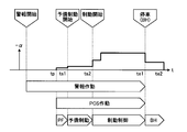
- FIG. 2 is an exemplary explanatory diagram illustrating transition of the control state by the vehicle collision avoidance control device of the embodiment.
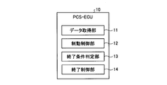
- FIG. 3 is an exemplary schematic block diagram of the vehicle collision avoidance control apparatus according to the embodiment.
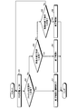
- FIG. 4 is an exemplary flowchart of termination control by the vehicle collision avoidance control apparatus according to the embodiment.
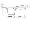
- FIG. 5 is an exemplary graph showing a change over time in the acceleration of the vehicle in a state that matches an end condition while the vehicle is stopped in the vehicle collision avoidance control apparatus of the embodiment.
- FIG. 1 is an exemplary schematic diagram of a vehicle on which the collision avoidance control device for a vehicle according to the embodiment is mounted.
- FIG. 2 is an exemplary explanatory diagram illustrating transition of the control state by the vehicle collision avoidance control device of the embodiment.
- FIG. 3 is an exemplary schematic block diagram of the vehicle collision avoidance control apparatus according to the
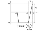
- FIG. 6 is an exemplary graph illustrating a change in acceleration of the vehicle over time in a state that matches a termination condition during movement of the vehicle in the collision avoidance control device for a vehicle according to the embodiment.
- FIG. 7 is an exemplary graph showing a change over time in the acceleration of the vehicle in a state that matches the termination condition at the time of failure in the vehicle collision avoidance control apparatus of the embodiment.
- each part of the vehicle 100 is controlled to avoid a collision with an obstacle ahead while the vehicle 100 is traveling forward is illustrated.
- FIG. 1 is an exemplary and schematic configuration diagram of the vehicle 100.
- the vehicle 100 includes an engine 51, a motor generator 62 (M / G), a brake device 41, and the like.
- Engine 51 and motor generator 62 cause acceleration of vehicle 100. Therefore, the engine 51 and the motor generator 62 can also be referred to as drive sources or drive devices.
- the vehicle 100 only needs to be equipped with at least one of the engine 51 and the motor generator 62 as a drive source. Further, the acceleration of the vehicle 100 is an increase over time of the speed toward the front of the vehicle 100 (time differentiation), and the deceleration of the vehicle 100 is a decrease over time of the speed toward the front of the vehicle 100 (time differentiation). ).
- the acceleration is also a negative deceleration
- the deceleration is also a negative acceleration. That is, the acceleration increases when the braking force or deceleration by the brake device 41 decreases, and the deceleration increases when the driving force or acceleration by the engine 51 or the motor generator 62 decreases.
- the vehicle 100 includes a PCS-ECU 10 (pre-crash safety electronic control unit).
- the PCS-ECU 10 detects that there is an obstacle ahead of the vehicle 100 based on the data acquired during traveling, the PCS-ECU 10 determines whether or not there is a possibility of a collision with the obstacle.
- the brake ECU 41 that controls the brake device 41, the engine 51, the motor generator 62, etc.
- the engine ECU 50 the M / GECU 60 (motor generator ECU), etc.
- the PCS-ECU 10 is an example of a collision avoidance control device.
- the PCS-ECU 10 instructs to control the acceleration or deceleration of the vehicle 100, that is, the driving force or the braking force, but the PCS-ECU 10 further instructs to control the steering of the vehicle 100. May be.
- the PCS-ECU 10 includes a control unit such as a CPU (central processing unit) and a controller, and a storage unit such as a ROM (read only memory), a RAM (random access memory), and a flash memory.
- the storage unit can store a program for operating the PCS-ECU 10, data used for arithmetic processing of the PCS-ECU 10, and the like.
- the vehicle 100 is equipped with a distance measuring device 21 and a camera 22.
- the distance measuring device 21 and the camera 22 are an example of an obstacle detection unit.
- the distance measuring device 21 is a device that wirelessly measures the distance to the obstacle without contact, and is, for example, a radar device or a sonar device.
- the PCS-ECU 10 acquires data indicating the distance from the obstacle from the distance measuring device 21.
- the data indicating the distance may be numerical data indicating the distance itself, or may be data having a value corresponding to the distance.
- the camera 22 is a digital camera incorporating an image sensor such as a CCD (charge coupled device) or a CIS (CMOS image sensor).
- the camera 22 can output moving image data at a predetermined frame rate.
- the PCS-ECU 10 may acquire data indicating an image captured by the camera 22 and acquire the distance to the obstacle using the image data.
- PCS-ECU 10 receives data indicating detection results from the various sensors from various sensors mounted on vehicle 100.
- the sensor mounted on the vehicle 100 may include a sensor that indicates a detection result of the state of the vehicle 100.
- Sensors indicating the detection result of the state of the vehicle 100 are, for example, a vehicle speed sensor, an acceleration sensor, a gyro sensor, and the like.
- the sensor mounted on the vehicle 100 may include a sensor that indicates a detection result of an operation amount or an operation request amount in an operation unit operated by a driver.
- the operation unit by the driver is, for example, an accelerator pedal, a brake pedal, a brake handle, a steering wheel, a switch, or the like.
- the sensor mounted on the vehicle 100 may include a sensor that indicates the detection result of the state of each device mounted on the vehicle 100.
- Devices mounted on the vehicle 100 are, for example, a brake device 41, an engine 51, a motor generator 62, an inverter 61 (IV), a steering system, a suspension system, and the like.
- the physical quantities detected by various sensors mounted on the vehicle 100 are, for example, distance, displacement, speed, acceleration, rotational speed, angle, angular velocity, angular acceleration, and the like.
- the PCS-ECU 10 may be input with numerical data indicating each physical quantity itself, or may be input with data corresponding to the magnitude of each physical quantity.
- the data input to the PCS-ECU 10 may be digital data, analog data such as non-numerical potentials, or data corresponding to on / off and stages instead of physical values. There may be.
- the PCS-ECU 10 calculates a predicted time to collide with an obstacle ahead, that is, TTC (time to collision) when performing collision avoidance control.
- TTC time to collision
- the TTC may be calculated in consideration of the relative acceleration of the obstacle, the deceleration of the vehicle 100, and the like. For example, the PCS-ECU 10 can determine that there is a possibility of a collision when the TTC is equal to or less than a predetermined value.
- the PCS-ECU 10 calculates the acceleration or deceleration of the vehicle 100 when performing collision avoidance control.
- the distribution ECU 30 calculates the share of the acceleration or deceleration set by the PCS-ECU 10 by the brake device 41, the engine 51, and the motor generator 62.
- the share ratio varies depending on the situation of the vehicle 100, for example.
- Distribution ECU 30 transmits data indicating acceleration or deceleration shared by brake ECU 40, engine ECU 50, and motor generator ECU 60 to each other.
- the brake ECU 40 controls the brake device 41 so that the acceleration or deceleration set by the PCS-ECU 10 can be obtained.
- the engine ECU 50 controls the engine 51 so that the acceleration or deceleration set by the PCS-ECU 10 can be obtained.
- motor generator ECU 60 controls inverter 61 so that motor generator 62 operates so that the acceleration or deceleration set by PCS-ECU 10 can be obtained.
- the brake ECU 40 can control the stop lamp 42 provided at the rear end of the vehicle 100 to light up.
- the lighting of the stop lamp 42 can be an alarm display for the surroundings of the vehicle 100, for example, the following vehicle.
- meter ECU70 can control the meter 71 provided in the instrument panel etc. so that a warning display may be output.
- the display output of the meter 71 can be an alarm display for the driver and passengers in the passenger compartment.
- the stop lamp 42 and the meter 71 can also be referred to as an alarm output device, an output device, an alarm device, a display output device, or the like.
- an audio output can be output from an audio output device (not shown).
- the audio output device is, for example, a speaker or a buzzer, and can also be called an alarm output device, an output device, an alarm device, or the like.
- FIG. 2 shows an example of the transition of the control state in the automatic collision avoidance control when the driver does not perform the brake operation.
- the horizontal axis represents time t
- the vertical axis represents deceleration
- ⁇ represents acceleration.
- the vertical axis in FIG. 2 is a required value for acceleration or deceleration.
- the PCS-ECU 10 calculates TTC at predetermined time intervals based on data acquired while the vehicle 100 is traveling, and starts collision avoidance control or performs collision avoidance control according to this TTC value. To the next stage, or the collision avoidance control is terminated. That is, the PCS-ECU 10 monitors the situation related to collision avoidance based on the TTC.
- the PCS-ECU 10 starts an alarm operation by the meter 71 or a speaker.
- the PCS-ECU 10 gives the brake ECU 40 an operation command that causes a slight deceleration of the vehicle 100 for a certain period of time, so that the brake ECU 40 drives a pump (not shown) of the brake device 41, and Clear the gap between the brake pads and the rotor, i.e. the brake disc or drum.
- This operation can also be referred to as prefill (PF).
- PF prefill
- the PCS-ECU 10 instructs the brake ECU 40 to perform preliminary braking for a certain period. Specifically, the PCS-ECU 10 transmits an instruction signal to the brake ECU 40 so that the stop lamp 42 is lit. Further, for example, the PCS-ECU 10 instructs the brake ECU 40 to obtain the minimum necessary deceleration (braking force) accompanying the lighting of the stop lamp 42, and the brake ECU 40 controls the brake device 41 based on the instruction. .
- the main purpose of the preliminary braking is to turn on the stop lamp 42, but a required deceleration that makes the driver of the rear vehicle aware of the deceleration operation may be obtained.
- the PCS-ECU 10 instructs the brake ECU 40 to start braking control for the purpose of avoiding a collision. Specifically, the PCS-ECU 10 instructs the brake ECU 40 to change the speed of the vehicle 100 at a required deceleration, that is, to obtain a required braking force, and the brake ECU 40 determines a brake device based on the instruction. 41 is controlled. In the braking control, the deceleration (braking force) may increase stepwise. The deceleration in the braking control is larger than the prefill and preliminary braking decelerations.
- the PCS-ECU 10 instructs the brake ECU 40 to maintain the stopped state for a predetermined period, and the brake ECU 40 controls the brake device 41 based on the instruction. To do.
- This operation can also be referred to as a brake hold (BH).
- the distribution ECU 30 can share the braking force with the motor generator 62 and the engine 51 according to the situation.
- the PCS-ECU 10 can end the above-described collision avoidance control by an operation of an accelerator pedal or a steering wheel by the driver, that is, an acceleration request operation, a steering operation, or the like.
- the PCS-ECU 10 includes a data acquisition unit 11, a braking control unit 12, an end condition determination unit 13, an end control unit 14 and the like as illustrated in FIG.
- operations for canceling the collision avoidance control such as an acceleration request operation and a steering operation, are simply referred to as a release operation below.
- the PCS-ECU 10 may be an independent ECU, or may be incorporated in an ECU of any system mounted on the vehicle.
- the PCS-ECU 10 can execute processes in accordance with installed and loaded programs to realize each function. That is, by executing the process according to the program, the PCS-ECU 10 can function as the data acquisition unit 11, the braking control unit 12, the end condition determination unit 13, the end control unit 14, and the like. Note that at least some of the functions of the above-described units may be realized by hardware.
- the data acquisition unit 11 can acquire data used for termination control.
- the data used for the end control is, for example, data indicating the operation amount of the acceleration request, data indicating the operation amount of the steering, data indicating the vehicle speed, data based on the fail determination, and the like.
- the data for fail determination is data indicating that the control by the PCS-ECU 10 has become unreliable, for example, data indicating failure of various sensors, failure of the motor or solenoid of the brake device 41, and the like. It is.
- the braking control unit 12 executes the PCS operation of FIG. 2, that is, the above-described prefill, preliminary braking, braking control, and brake hold.
- the braking control unit 12 is an example of a collision avoidance control unit.
- the end condition determination unit 13 determines whether or not the end condition determination unit 13 satisfies any one of a plurality of end conditions controlled by the braking control unit 12.
- the end conditions are the following (1) to (3).
- the vehicle 100 is moving, that is, during the PCS operation, specifically, prefill, standby.
- a predetermined amount of release operation is performed in the state of braking or braking control
- the termination condition determination unit 13 determines termination at predetermined time intervals. Running.
- the end condition determination unit 13 is an example of an end determination unit.
- (1) may also be referred to as a stop condition during stopping.
- (2) may also be referred to as a moving end condition.
- (3) can also be referred to as a failure determination condition.
- the predetermined amount of the release operation of (1) and (2) can be set for each of (1) and (2). Further, the predetermined amount of the releasing operation (2) may be set to a different value depending on the speed of the vehicle 100.
- the brake control device 14 When it is determined by the end condition determining unit 13 that the end control unit 14 is in a state satisfying any one of the plurality of end conditions, the brake control device 14 is configured so that the deceleration or acceleration corresponding to the end condition is obtained. 41, at least one of the engine 51 and the motor generator 62 is controlled.
- FIG. 4 shows an example of an end control procedure according to the present embodiment.
- S1 PCS operation or BH (S1)
- the end control unit 14 executes end control 1 corresponding to the stop condition during stopping (S4).
- FIG. 5 exemplifies the change with time of acceleration ⁇ in the end control 1 when the vehicle is in a state that matches the stop condition at the time td1 in FIG. 5 slightly after the time te1 in FIG.
- the acceleration ⁇ 11 is, for example, an acceleration generated in the vehicle 100 in a state where the driver does not perform the acceleration requesting operation, that is, an acceleration that causes the vehicle 100 to cause a creep phenomenon.
- the increase rate of the acceleration ⁇ can also be referred to as increment, inclination, change with time, increase rate per unit time, acceleration time derivative, jerk, jerk, and the like.
- An increase in acceleration corresponds to a decrease in deceleration, an increase in driving force, a decrease in braking force, and the like.
- the increase rate of the acceleration ⁇ in the increase interval of the acceleration ⁇ is not necessarily constant, and may vary somewhat.
- the end control unit 14 linearly increases the acceleration ⁇ from ⁇ 11 to ⁇ 12 from time t11 to time t12.
- the increasing speed of the acceleration ⁇ in this section is A1 / T1.
- the increase rate A1 / T1 of the acceleration ⁇ is set to a value lower than the increase rate of the acceleration ⁇ between the time td1 and the time t11.
- the end control unit 14 selects a smaller one of the driver's requested acceleration and the acceleration ⁇ limited by the increasing speed A1 / T1 in the section from the time t11 to the time t12. )I do. That is, when the driver's required acceleration is smaller than the acceleration ⁇ due to the increased speed A1 / T1, the driver's required acceleration is selected, and when the driver's required acceleration is larger than the acceleration ⁇ due to the increased speed A1 / T1.
- the acceleration ⁇ with the increasing speed A1 / T1 is selected.
- the value of the increasing speed A1 / T1, that is, the values of ⁇ 11, ⁇ 12, t11, and t12 can be set in advance so as to prevent the vehicle from suddenly jumping out.
- the increasing speed A1 / T1 can be variably set according to the distance from the obstacle, the steering of the driver, and the like.
- the increase speed A1 / T1 may be set to be larger when the distance to the obstacle is smaller than the distance from the obstacle (for example, by decreasing T1).
- Such an end control 1 suppresses the vehicle 100 from suddenly starting from the time of stopping.
- the vehicle 100 when the vehicle is stopped or stopped, the vehicle 100 may not be completely stopped, and may be in a state of a predetermined speed or less, for example, 10 km / h or less.
- FIG. 6 illustrates the change over time of the acceleration ⁇ in the end control 2 when the moving end condition is met at the time td2 in FIG. 6 before the time te1 in FIG.
- the end control unit 14 linearly increases the acceleration ⁇ until it reaches ⁇ 22 at time t2.
- the increasing speed of the acceleration ⁇ in this section is A2 / T2.
- the increase rate A2 / T2 of the acceleration ⁇ is set to a value higher than the increase rate A1 / T1 of the acceleration ⁇ in the section where the acceleration ⁇ increases from ⁇ 11 to ⁇ 12 or the required acceleration in the end control 1.
- the end control unit 14 selects a smaller one of the driver's requested acceleration and the acceleration ⁇ limited by the increase speed A2 / T2 in the section from the time td2 to the time t2. )I do.
- the value of the increase speed A2 / T2, that is, the values of ⁇ 22 and t2 can be set in consideration of both reflection of the driver's operation and ensuring of vehicle stability at the time of release. Further, the increase speed A2 / T2 can be variably set according to the distance to the obstacle, the driver's steering, the driver's acceleration operation, and the like. As an example, when the depression amount (operation amount) of the driver's accelerator pedal is large or when the depression speed (operation speed) is steep, the increase speed A2 / T2 is larger than that when it is not. It may be set as follows.
- FIG. 7 illustrates the change with time of the acceleration ⁇ in the end control 3 in a case where the failure determination condition is met at time td3 in FIG. 7 before time te1 in FIG.
- the termination control unit 14 immediately terminates the braking control. That is, in other words, the braking control unit 12 immediately ends the braking control.
- the end control unit 14 uses the end condition determination unit 13 to select one of a plurality of end conditions, that is, the stop condition during stopping, the end condition during movement, and the fail determination condition.
- the brake device 41 and the drive device that is, the engine 51 and the motor generator 62 is controlled so as to achieve the deceleration or acceleration corresponding to the end condition. Therefore, according to the present embodiment, the collision avoidance control is terminated through a change in acceleration or deceleration set for each of a plurality of termination conditions. Therefore, for example, the collision avoidance control can be terminated more smoothly or safely depending on the situation.
- the end control unit 14 in a state that matches the stop condition during stopping, causes the brake device 41, so that the increase in acceleration toward the requested acceleration is limited. At least one of the engine 51 and the motor generator 62 is controlled. Therefore, according to the present embodiment, the collision avoidance control is terminated after a change in the acceleration or deceleration of the vehicle corresponding to the stopped state of the vehicle 100, specifically, for example, a relatively moderate increase in acceleration. Therefore, the collision avoidance control can be finished more smoothly or safely.
- the end control unit 14 in a state that matches the moving end condition, increases the acceleration toward the requested acceleration higher than when the acceleration matches the stopping end condition. At least one of the brake device 41, the engine 51, and the motor generator 62 is controlled so as to increase. Therefore, according to the present embodiment, for example, the collision avoidance control is performed through a change in the acceleration or deceleration of the vehicle corresponding to the moving state of the vehicle 100, specifically, for example, through a relatively sudden increase in acceleration. Therefore, the collision avoidance control can be completed more smoothly or safely.
- the end control unit 14 immediately ends the control by the brake control unit 12 (collision avoidance control unit) in a state that matches the end condition by the failure. Therefore, according to the present embodiment, for example, the collision avoidance control is immediately terminated at the time of a failure, so that it is possible to suppress an adverse effect due to the failure.
Landscapes
- Engineering & Computer Science (AREA)
- Mechanical Engineering (AREA)
- Transportation (AREA)
- Automation & Control Theory (AREA)
- Regulating Braking Force (AREA)
- Valves And Accessory Devices For Braking Systems (AREA)
- Control Of Driving Devices And Active Controlling Of Vehicle (AREA)
Abstract
実施形態の車両の衝突回避制御装置は、例えば、衝突回避制御部と、衝突回避制御部による制御の実行中に、運転者による運転操作が行われた場合、あるいは衝突回避制御部による制御を正常に行えないフェイルが生じた場合に、衝突回避制御部による制御の異なる複数の終了条件のうちいずれかを満たす状態であるか否かを判定する終了判定部と、終了判定部で複数の終了条件のうちのいずれかを満たす状態であることが判定された場合に、当該終了条件に対応した減速度または加速度となるようブレーキ装置および駆動装置のうち少なくとも一方を制御する終了制御部と、を備える。
Description
本発明は、車両の衝突回避制御装置および衝突回避制御方法に関する。
従来、衝突回避のため車両に制動力を生じさせた後に駆動力を復帰させる際に、複数の復帰モードの中から選択した一つの復帰モードにより駆動力を復帰させる、車両の衝突回避制御装置が知られている(例えば、特許文献1)。この種の衝突回避制御装置は、近年装着が拡大しており、また作動速度など使用される領域の拡大や回避性能の向上などが求められている。
この種の車両の衝突回避制御装置では、衝突回避制御中に、運転者によって車両を運転する操作、例えば、加速要求操作や操舵操作等が行われた場合や、衝突回避制御を正常に行えないフェイルが生じた場合等にあっても、より円滑にあるいはより安全に衝突回避制御を終了して通常運転に復帰できることが望ましい。
そこで、本発明の課題の一つは、例えば、衝突回避制御中に運転者によって車両を運転する操作が行われた場合や衝突回避制御装置のフェイルが生じた場合に、より円滑にあるいはより安全に衝突回避制御を終了することが可能な、車両の衝突回避制御装置を得ることである。
本発明の車両の衝突回避制御装置は、例えば、走行中に取得されたデータに基づいて、障害物との衝突を避けるよう少なくともブレーキ装置を制御する衝突回避制御部と、上記衝突回避制御部による制御の実行中に、運転者による運転操作が行われた場合、あるいは上記衝突回避制御部による制御を正常に行えないフェイルが生じた場合に、上記衝突回避制御部による制御の異なる複数の終了条件のうちいずれかを満たす状態であるか否かを判定する終了判定部と、上記終了判定部で上記複数の終了条件のうちのいずれかを満たす状態であることが判定された場合に、当該終了条件に対応した減速度または加速度となるようブレーキ装置および駆動装置のうち少なくとも一方を制御する終了制御部と、を備える。
上記車両の衝突回避制御装置によれば、例えば、衝突回避制御が実行されている状態で運転者によって車両を運転する操作が行われた場合や衝突回避制御装置のフェイルが生じた場合に、終了条件毎に設定された加速度または減速度の変化を経て、衝突回避制御が終了されうる。よって、上記車両の衝突回避制御装置によれば、例えば、状況に応じてより円滑にあるいはより安全に衝突回避制御が終了されうる。
また、上記車両の衝突回避制御装置では、例えば、上記終了制御部は、運転者による運転操作が行われた場合における停車中の終了条件と合致した状態にあっては、要求された加速度に向けての加速度の時間的な増加が制限されるよう、上記ブレーキ装置および上記駆動装置のうち少なくとも一方を制御する。よって、上記車両の衝突回避制御装置によれば、例えば、停車中の状態に対応した車両の加速度または減速度の変化を経て衝突回避制御が終了されるため、より円滑にあるいはより安全に衝突回避制御が終了されうる。
また、上記車両の衝突回避制御装置では、例えば、上記終了制御部は、運転者による運転操作が行われた場合における移動中の終了条件と合致した状態にあっては、要求された加速度に向けて、加速度が、上記停車中の終了条件と合致した場合よりも高い増加速度で増加するよう、上記ブレーキ装置および上記駆動装置のうち少なくとも一方を制御する。よって、上記車両の衝突回避制御装置によれば、例えば、移動中の状態に対応した車両の加速度または減速度の変化を経て衝突回避制御が終了されるため、より円滑にあるいはより安全に衝突回避制御が終了されうる。
また、上記車両の衝突回避制御装置では、例えば、上記終了制御部は、フェイルによる終了条件と合致した状態にあっては、上記衝突回避制御部による制御を直ちに終了する。よって、上記車両の衝突回避制御装置によれば、例えば、フェイル時には衝突回避制御が直ちに終了されるため、フェイルによる悪影響が生じるのが抑制されうる。
また、本発明の衝突回避制御方法では、例えば、コンピュータが、走行中に取得されたデータに基づいて、障害物との衝突を避けるよう少なくともブレーキ装置を制御し、上記障害物との衝突を避けるための制御中に、上記ブレーキ装置の制御の異なる複数の終了条件のうちいずれかを満たす状態であるか否かを判定し、上記複数の終了条件のうちのいずれかを満たす状態であることが判定された場合に、当該終了条件に対応した減速度または加速度となるようブレーキ装置および駆動装置のうち少なくとも一方を制御する。
上記車両の衝突回避制御方法では、例えば、運転者による運転操作が行われた場合における停車中の終了条件と合致した状態にあっては、減速度または加速度の単位時間あたりの変化量が制限されるよう、上記ブレーキ装置および上記駆動装置のうち少なくとも一方が制御される。よって、上記車両の衝突回避制御方法によれば、例えば、停車中の状態に対応した車両の加速度または減速度の変化を経て衝突回避制御が終了されるため、より円滑にあるいはより安全に衝突回避制御が終了されうる。
以下、本発明の例示的な実施形態が開示される。以下に示される実施形態の構成、ならびに当該構成によってもたらされる作用および結果(効果)は、一例である。本発明は、以下の実施形態に開示される構成以外によっても実現可能である。また、本発明によれば、構成によって得られる種々の効果(派生的な効果も含む)のうち少なくとも一つを得ることが可能である。
また、以下では、一例として、車両100が、前方に走行中に、前方の障害物との衝突を回避するよう車両100の各部が制御される場合が、例示される。
図1は、車両100の例示的かつ模式的な構成図である。図1に示すように、車両100は、エンジン51や、モータジェネレータ62(M/G)、ブレーキ装置41等を備えている。エンジン51およびモータジェネレータ62は、車両100の加速度を生じさせる。よって、エンジン51およびモータジェネレータ62は、駆動源あるいは駆動装置とも称されうる。なお、車両100には、駆動源としては、エンジン51およびモータジェネレータ62のうち少なくとも一方が搭載されていればよい。また、車両100の加速度は、車両100の前方へ向かう速度の経時的な増分(時間微分)であり、車両100の減速度は、車両100の前方へ向かう速度の経時的な減分(時間微分)である。よって、加速度は、負の減速度でもあり、減速度は、負の加速度でもある。つまり、ブレーキ装置41による制動力すなわち減速度が減ると加速度が増大し、エンジン51やモータジェネレータ62による駆動力すなわち加速度が減ると減速度が増大する。
車両100は、PCS-ECU10(pre-crash safety electronic control unit)を備えている。PCS-ECU10は、走行中に取得されたデータに基づいて、車両100の前方に障害物があることが検知された場合に、当該障害物との衝突の可能性の有無を判定し、衝突の可能性がある場合に、当該障害物との衝突を回避するよう、ブレーキ装置41や、エンジン51、モータジェネレータ62等を制御するブレーキECU40や、エンジンECU50、M/GECU60(motor generator ECU)等へ指示する。PCS-ECU10は、衝突回避制御装置の一例である。なお、本実施形態では、PCS-ECU10は、車両100の加速度または減速度、すなわち駆動力または制動力を制御するよう指示するが、PCS-ECU10は、さらに、車両100の操舵を制御するよう指示してもよい。
PCS-ECU10は、CPU(central processing unit)やコントローラ等の制御部や、ROM(read only memory)や、RAM(random access memory)、フラッシュメモリ等の記憶部を、有している。記憶部には、PCS-ECU10を動作させるためのプログラムや、PCS-ECU10の演算処理に用いられるデータ等が記憶されうる。
また、車両100には、測距装置21や、カメラ22が搭載されている。測距装置21およびカメラ22は、障害物検出部の一例である。
測距装置21は、障害物との距離を非接触で無線により測定する装置であり、例えば、レーダ装置や、ソナー装置等である。PCS-ECU10は、測距装置21から、障害物との距離を示すデータを取得する。この場合、距離を示すデータは、距離そのものを示す数値のデータであってもよいし、距離に対応した値のデータであってもよい。
カメラ22は、例えば、CCD(charge coupled device)やCIS(CMOS image sensor)等の撮像素子を内蔵するデジタルカメラである。カメラ22は、所定のフレームレートで動画データを出力することができる。PCS-ECU10は、カメラ22で撮像された画像を示すデータを取得し、当該画像データを用いて、障害物までの距離を取得してもよい。
また、図示されないが、PCS-ECU10には、車両100に搭載される各種センサから、当該各種センサによる検出結果を示すデータが入力される。車両100に搭載されるセンサには、車両100の状態の検出結果を示すセンサが含まれうる。車両100の状態の検出結果を示すセンサは、例えば、車速センサや、加速度センサ、ジャイロセンサ等である。
また、車両100に搭載されるセンサには、運転者によって操作される操作部における操作量あるいは操作要求量の検出結果を示すセンサが含まれうる。運転者による操作部は、例えば、アクセルペダルや、ブレーキペダル、ブレーキハンドル、ステアリングホイール、スイッチ等である。
また、車両100に搭載されるセンサには、車両100に搭載される各装置の状態の検出結果を示すセンサが含まれうる。車両100に搭載される装置は、例えば、ブレーキ装置41や、エンジン51、モータジェネレータ62、インバータ61(IV)、操舵システム、サスペンションシステム等である。なお、車両100に搭載される各種センサによって検出される物理量は、例えば、距離、変位、速度、加速度、回転速度、角度、角速度、角加速度等である。また、PCS-ECU10には、各物理量そのものを示す数値のデータが入力されてもよいし、各物理量の大きさに対応した値のデータが入力されてもよい。
PCS-ECU10に入力されるデータは、デジタルデータであってもよいし、数値化されていない電位等のアナログデータであってもよいし、物理量の値ではなくオンオフや段階に対応したデータ等であってもよい。
PCS-ECU10は、衝突回避制御を行うにあたり、前方の障害物と衝突するまでの予測時間、すなわちTTC(time to collision)を算出する。最も単純な例では、障害物までの距離をDs、障害物に対する車両100の相対速度をVrとすると、PCS-ECU10は、TTCを、TTC=Ds/Vrのような式によって算出することができる。なお、TTCは、障害物の相対加速度や、車両100の減速度等を考慮して算出されてもよい。PCS-ECU10は、例えば、TTCが所定値以下である場合に、衝突可能性が有ると判断することができる。
また、PCS-ECU10は、衝突回避制御を行う際の車両100の加速度または減速度を演算する。分配ECU30は、PCS-ECU10によって設定された加速度または減速度の、ブレーキ装置41、エンジン51、およびモータジェネレータ62のそれぞれによる分担を演算する。分担の割合は、例えば車両100の状況に応じて異なる。分配ECU30は、ブレーキECU40、エンジンECU50、およびモータジェネレータECU60に、それぞれが分担する加速度または減速度を示すデータを送信する。
ブレーキECU40は、PCS-ECU10で設定された加速度または減速度が得られるよう、ブレーキ装置41を制御する。エンジンECU50は、PCS-ECU10で設定された加速度または減速度が得られるよう、エンジン51を制御する。また、モータジェネレータECU60は、PCS-ECU10で設定された加速度または減速度が得られるようにモータジェネレータ62が動作するよう、インバータ61を制御する。
ブレーキECU40は、車両100の後端部に設けられたストップランプ42を、点灯するよう制御することができる。ストップランプ42の点灯は、車両100の周囲、例えば後続車等に対する警報表示となりうる。また、メータECU70は、インストルメントパネル等に設けられたメータ71を、警報表示を出力するよう、制御することができる。メータ71の表示出力は、運転者や車室内の乗員に対する警報表示となりうる。ストップランプ42およびメータ71は、警報出力装置や、出力装置、警報装置、表示出力装置等とも称されうる。なお、音声による出力は、図示されない音声出力装置から出力されうる。音声出力装置は、例えば、スピーカやブザー等であり、警報出力装置や、出力装置、警報装置等とも称されうる。
図2は、運転者によるブレーキ操作が行われなかった場合の自動的な衝突回避制御における、制御状態の遷移の一例が示されている。なお、図2に含まれるグラフにおいて、横軸は時間t、縦軸は減速度、αは加速度である。図2の縦軸は、加速度または減速度の要求値である。
PCS-ECU10は、車両100の走行中に取得されたデータに基づいて、所定の時間間隔でTTCを算出し、このTTCの値に応じて、衝突回避制御を開始したり、衝突回避制御を次の段階に遷移させたり、衝突回避制御を終了したりする。すなわち、PCS-ECU10は、TTCに基づいて、衝突回避に関わる状況を監視している。
まず、PCS-ECU10は、メータ71やスピーカ等による警報作動を開始する。
次に、PCS-ECU10は、一定期間、微少な車両100の減速度を生じさせるような動作指令をブレーキECU40に与えることにより、ブレーキECU40はブレーキ装置41のポンプ(不図示)を駆動させるとともに、ブレーキパッドとロータ、すなわちブレーキディスクあるいはドラムとの間の隙間を解消する。この動作は、プレフィル(PF)とも称されうる。プレフィルにより、ポンプが駆動されることで、ポンプが止まった状態からブレーキ力を増大させる場合に比べて応答性が高くなり、また、隙間、すなわち無効ストロークが解消されるため、衝突回避制御の開始の応答性が向上する。
次に、PCS-ECU10は、一定期間、予備制動を行うようブレーキECU40へ指示する。具体的には、PCS-ECU10は、ストップランプ42が点灯されるよう、ブレーキECU40に指示信号を送信する。また、PCS-ECU10は、例えば、ストップランプ42の点灯に伴う必要最低限度の減速度(制動力)が得られるよう、ブレーキECU40へ指示し、ブレーキECU40は指示に基づいてブレーキ装置41を制御する。なお、本実施形態では、予備制動の主目的はストップランプ42の点灯であるが、後方車両の運転者に減速操作を意識付けるような所要の減速度が得られるようにしてもよい。
次に、PCS-ECU10は、衝突回避を目的とした制動制御を開始するようブレーキECU40へ指示する。具体的には、PCS-ECU10は、車両100の速度が所要の減速度で変化するよう、すなわち、所要の制動力が得られるよう、ブレーキECU40へ指示し、ブレーキECU40は指示に基づいてブレーキ装置41を制御する。なお、制動制御にあっては、減速度(制動力)が段階的に増大してもよい。制動制御における減速度は、プレフィルおよび予備制動の減速度よりも大きい。
車両100が障害物に衝突することなく停車すると、PCS-ECU10は、所定期間、車両100が停車状態を維持するよう、ブレーキECU40へ指示し、ブレーキECU40は、指示に基づいてブレーキ装置41を制御する。この動作は、ブレーキホールド(BH)とも称されうる。
なお、上述した各段階において、分配ECU30は、状況に応じて、制動力を、モータジェネレータ62やエンジン51に分担させうる。
また、本実施形態では、PCS-ECU10は、運転者によるアクセルペダルや、ステアリングホイールなどの操作、すなわち、加速要求操作や、操舵操作等によって、上述した衝突回避制御を終了することができる。そのために、PCS-ECU10は、図3に例示されるように、データ取得部11や、制動制御部12、終了条件判定部13、終了制御部14等を有している。なお、加速要求操作や、操舵操作等、衝突回避制御を解除する操作は、以下では単に、解除操作と称される。
PCS-ECU10は、独立したECUであってもよいし、車両に搭載されたいずれかのシステムのECUに組み込まれてもよい。PCS-ECU10は、インストールされ、ロードされたプログラムにしたがって処理を実行し、各機能を実現することができる。すなわち、プログラムにしたがって処理が実行されることにより、PCS-ECU10は、データ取得部11や、制動制御部12、終了条件判定部13、終了制御部14等として機能することができる。なお、上記各部の機能の少なくとも一部は、ハードウエアによって実現されてもよい。
データ取得部11は、終了制御に用いられるデータを取得することができる。終了制御に用いられるデータとは、例えば、加速要求の操作量を示すデータや、操舵の操作量を示すデータ、車速を示すデータ、フェイル判定の元にするデータ等である。フェイル判定の元にするデータは、PCS-ECU10による制御が信頼できない状態となったことを示すデータであって、例えば、各種センサの故障や、ブレーキ装置41のモータやソレノイドの故障等を示すデータである。
制動制御部12は、図2のPCS作動、すなわち、上述したプレフィルや、予備制動、制動制御、およびブレーキホールドを実行する。制動制御部12は、衝突回避制御部の一例である。
終了条件判定部13は、データ取得部11で取得されたデータに基づいて、制動制御部12による制御の異なる複数の終了条件のうちいずれかを満たす状態であるか否かを判定する。本実施形態では、終了条件は、以下の(1)~(3)である。
(1)車両100が停車中、すなわち、ブレーキホールドの状態で、所定量の解除操作が行われた場合
(2)車両100が移動中、すなわち、PCS作動中、具体的には、プレフィル、予備制動、または制動制御の状態で、所定量の解除操作が行われた場合
(3)PCS作動中の状態で、フェイルが生じた場合
終了条件判定部13は、所定の時間間隔で、終了判定を実行している。終了条件判定部13は、終了判定部の一例である。なお、(1)は、停車中終了条件とも称されうる。(2)は、移動中終了条件とも称されうる。また、(3)は、フェイル判定条件とも称されうる。(1)および(2)の解除操作の所定量は、(1)および(2)のそれぞれについて設定されうる。また、(2)の解除操作の所定量は、車両100の速度により異なる値に設定されてもよい。
(1)車両100が停車中、すなわち、ブレーキホールドの状態で、所定量の解除操作が行われた場合
(2)車両100が移動中、すなわち、PCS作動中、具体的には、プレフィル、予備制動、または制動制御の状態で、所定量の解除操作が行われた場合
(3)PCS作動中の状態で、フェイルが生じた場合
終了条件判定部13は、所定の時間間隔で、終了判定を実行している。終了条件判定部13は、終了判定部の一例である。なお、(1)は、停車中終了条件とも称されうる。(2)は、移動中終了条件とも称されうる。また、(3)は、フェイル判定条件とも称されうる。(1)および(2)の解除操作の所定量は、(1)および(2)のそれぞれについて設定されうる。また、(2)の解除操作の所定量は、車両100の速度により異なる値に設定されてもよい。
終了制御部14は、終了条件判定部13で複数の終了条件のうちのいずれかを満たす状態であることが判定された場合に、当該終了条件に対応した減速度または加速度となるよう、ブレーキ装置41、エンジン51、およびモータジェネレータ62のうち少なくともいずれか一つを制御する。
図4には、本実施形態による終了制御の手順の一例が示されている。PCS作動またはBH中(S1)、終了条件判定部13による終了判定において、フェイル判定条件に合致せず(S2でNo)、停車中終了条件に合致した場合にあっては(S3でYes)、終了制御部14は、停車中終了条件に対応した終了制御1を実行する(S4)。
図5には、図2の時刻te1を若干過ぎた図5の時刻td1において停車中終了条件に合致した状態となった場合における、終了制御1での加速度αの経時変化が例示されている。時刻td1で停車中終了条件に合致すると、終了制御部14は、まずは比較的速やかに、加速度αを時刻t11でα=0となるまで線形的に増大させ、さらに、時刻t11で、直ちに加速度α11(>0)となるまで加速度αを増大させる。ここで、加速度α11は、例えば、運転者が加速要求操作を行わない状態で車両100に生じる加速度、すなわち、車両100にクリープ現象を生じさせる加速度である。終了制御1においては、加速度α=0となるまで、すなわち時刻td1から時刻t11までの加速度αの増加速度は固定されている。なお、加速度αの増加速度は、増分や、傾き、経時変化、単位時間あたりの増加率、加速度の時間微分、加加速度、ジャーク等とも称されうる。また、加速度の増大は、減速度の減少や、駆動力の増大、制動力の減少等に相当する。また、加速度αの増加区間中における加速度αの増加速度は、必ずしも一定でなくてよく、多少の変動があってもよい。
次いで、終了制御部14は、時刻t11から時刻t12までの間、加速度αをα11からα12まで線形的に増大させる。この区間での加速度αの増加速度は、A1/T1である。図5の例では、A1=α12-α11、T1=t12-t11である。なお、加速度αの増加速度A1/T1は、時刻td1から時刻t11の間の加速度αの増加速度よりも低い値に設定されている。
終了制御1では、終了制御部14は、時刻t11から時刻t12までの区間で、運転者の要求加速度と増加速度A1/T1で制限された加速度αとの小さい方を選択するミニマムセレクト(minimum select)を行う。すなわち、増加速度A1/T1による加速度αよりも運転者の要求加速度が小さい場合は、運転者の要求加速度が選択され、増加速度A1/T1による加速度αよりも運転者の要求加速度が大きい場合は、増加速度A1/T1による加速度αが選択される。増加速度A1/T1の値、すなわちα11,α12,t11,t12の値は、車両の急な飛び出しを防止するような値に予め設定されうる。また、増加速度A1/T1は、障害物との距離や運転者の操舵等に応じて可変設定されうる。一例としては、障害物との距離が小さいよりも大きい方が増加速度A1/T1が大きくなるよう(例えば、T1を小さくするなどにより)、設定されてもよい。
このような終了制御1によれば、車両100が停車時から急発進するのが抑制される。なお、本実施形態では、停車時あるいは停車中とは、車両100が完全に停車していなくてもよく、所定速度以下、例えば10km/h以下等の状態であってもよい。
また、図4のS3において、停車中終了条件に合致せず(S3でNo)、移動中終了条件に合致した場合にあっては(S5でYes)、終了制御部14は、移動中終了条件に対応した終了制御2を実行する(S6)。
図6には、図2の時刻te1よりも前の図6の時刻td2において移動中終了条件に合致した状態となった場合における、終了制御2での加速度αの経時変化が例示されている。時刻td2で移動中終了条件に合致すると、終了制御部14は、比較的速やかに、加速度αを時刻t2でα22となるまで線形的に増大させる。この区間での加速度αの増加速度は、A2/T2である。図6の例では、A2=α22-α21、T2=t2-td2である。加速度αの増加速度A2/T2は、終了制御1において加速度αがα11からα12または要求加速度まで増大する区間の加速度αの増加速度A1/T1よりも高い値に設定されている。
終了制御2では、終了制御部14は、時刻td2から時刻t2までの区間で、運転者の要求加速度と増加速度A2/T2で制限された加速度αとの小さい方を選択するミニマムセレクト(minimum select)を行う。増加速度A2/T2の値、すなわちα22,t2の値は、運転者の操作の反映と解除時の車両安定性の確保との双方を考慮して設定されうる。また、増加速度A2/T2は、障害物との距離や、運転者の操舵、運転者の加速操作等に応じて可変設定されうる。一例としては、運転者のアクセルペダルの踏込量(操作量)が大きい場合や、踏込速度(操作速度)が急な場合にあっては、そうでない場合に比べて増加速度A2/T2が大きくなるように、設定されてもよい。
このような終了制御2によれば、前方障害物が移動した場合や、前方障害物が移動することが運転者が予測できるような場合において、運転者による操作を速やかに反映した車両100の挙動が得られる。よって、例えば、より安全な状態が維持されやすい。
また、図4のS2において、フェイル判定条件に合致した場合にあっては(S2でYes)、終了制御部14は、フェイル判定条件に対応した終了制御3を実行する(S7)。
図7には、図2の時刻te1よりも前の図7の時刻td3においてフェイル判定条件に合致した状態となった場合における、終了制御3での加速度αの経時変化が例示されている。時刻td3でフェイル判定条件に合致すると、終了制御部14は、直ちに制動制御を終了させる。すなわち、換言すれば、制動制御部12は、直ちに制動制御を終了する。
このような終了制御3によれば、衝突回避システムでフェイルが生じた場合に、当該フェイルによる悪影響が生じるのを直ちに回避することができる。
なお、フェイル判定条件に合致せず(S2でNo)、停車中終了条件に合致せず(S3でNo)、かつ移動中終了条件にも合致しない場合にあっては(S5でNo)、S1に戻る。また、S2、S3、およびS5の順序は変更可能である。
以上、説明したように、本実施形態では、終了制御部14は、終了条件判定部13で複数の終了条件、すなわち停車中終了条件、移動中終了条件、およびフェイル判定条件のうちのいずれかを満たす状態であることが判定された場合に、当該終了条件に対応した減速度または加速度となるようブレーキ装置41および駆動装置、すなわちエンジン51およびモータジェネレータ62のうち少なくとも一方を制御する。よって、本実施形態によれば、複数の終了条件毎に設定された加速度または減速度の変化を経て、衝突回避制御が終了される。よって、例えば、状況に応じてより円滑にあるいはより安全に衝突回避制御が終了されうる。
また、本実施形態では、停車中終了条件と合致した状態にあっては、終了制御部14は、要求された加速度に向けての加速度の時間的な増加が制限されるよう、ブレーキ装置41、エンジン51、およびモータジェネレータ62のうち少なくとも一つを制御する。よって、本実施形態によれば、車両100の停車中の状態に対応した車両の加速度または減速度の変化、具体的には、例えば、比較的緩やかな加速度の増大を経て、衝突回避制御が終了されるため、より円滑にあるいはより安全に衝突回避制御が終了されうる。
また、本実施形態では、移動中終了条件と合致した状態にあっては、終了制御部14は、要求された加速度に向けて、加速度が、停車中終了条件と合致した場合よりも高い増加速度で増加するよう、ブレーキ装置41、エンジン51、およびモータジェネレータ62のうち少なくとも一つを制御する。よって、本実施形態によれば、例えば、車両100の移動中の状態に対応した車両の加速度または減速度の変化、具体的には、例えば、比較的急な加速度の増大を経て、衝突回避制御が終了されるため、より円滑にあるいはより安全に衝突回避制御が終了されうる。
また、本実施形態では、フェイルによる終了条件と合致した状態にあっては、終了制御部14は、制動制御部12(衝突回避制御部)による制御を直ちに終了する。よって、本実施形態によれば、例えば、フェイル時には衝突回避制御が直ちに終了されるため、フェイルによる悪影響が生じるのが抑制されうる。
以上、本発明の実施形態が例示されたが、上記実施形態は一例であって、発明の範囲を限定することは意図していない。上記実施形態は、その他の様々な形態で実施されることが可能であり、発明の要旨を逸脱しない範囲で、種々の省略、置き換え、組み合わせ、変更を行うことができる。また、上記実施形態における構成、部品、数、時間、速度、加速度等のスペックは、種々に変更して実施することができる。
12…制動制御部(衝突回避制御部)、13…終了条件判定部(終了判定部)、14…終了制御部、41…ブレーキ装置、51…エンジン(駆動装置)、62…モータジェネレータ(駆動装置)、100…車両。
Claims (5)
- 走行中に取得されたデータに基づいて、障害物との衝突を避けるよう少なくともブレーキ装置を制御する衝突回避制御部と、
前記衝突回避制御部による制御の実行中に、運転者による運転操作が行われた場合、あるいは前記衝突回避制御部による制御を正常に行えないフェイルが生じた場合に、前記衝突回避制御部による制御の異なる複数の終了条件のうちいずれかを満たす状態であるか否かを判定する終了判定部と、
前記終了判定部で前記複数の終了条件のうちのいずれかを満たす状態であることが判定された場合に、当該終了条件に対応した減速度または加速度となるようブレーキ装置および駆動装置のうち少なくとも一方を制御する終了制御部と、
を備えた、車両の衝突回避制御装置。 - 前記終了制御部は、運転者による運転操作が行われた場合における停車中の終了条件と合致した状態にあっては、要求された加速度に向けての加速度の時間的な増加が制限されるよう、前記ブレーキ装置および前記駆動装置のうち少なくとも一方を制御する、請求項1に記載の車両の衝突回避制御装置。
- 前記終了制御部は、運転者による運転操作が行われた場合における移動中の終了条件と合致した状態にあっては、要求された加速度に向けて、加速度が、前記停車中の終了条件と合致した場合よりも高い増加速度で増加するよう、前記ブレーキ装置および前記駆動装置のうち少なくとも一方を制御する、請求項2に記載の車両の衝突回避制御装置。
- 前記終了制御部は、フェイルによる終了条件と合致した状態にあっては、前記衝突回避制御部による制御を直ちに終了する、請求項1~3のうちいずれか一つに記載の車両の衝突回避制御装置。
- コンピュータが、
走行中に取得されたデータに基づいて、障害物との衝突を避けるよう少なくともブレーキ装置を制御し、
前記障害物との衝突を避けるための制御中に、前記ブレーキ装置の制御の異なる複数の終了条件のうちいずれかを満たす状態であるか否かを判定し、
前記複数の終了条件のうちのいずれかを満たす状態であることが判定された場合に、当該終了条件に対応した減速度または加速度となるようブレーキ装置および駆動装置のうち少なくとも一方を制御する、
車両の衝突回避制御方法。
Applications Claiming Priority (2)
| Application Number | Priority Date | Filing Date | Title |
|---|---|---|---|
| JP2015143479A JP2017024496A (ja) | 2015-07-17 | 2015-07-17 | 車両の衝突回避制御装置および衝突回避制御方法 |
| JP2015-143479 | 2015-07-17 |
Publications (1)
| Publication Number | Publication Date |
|---|---|
| WO2017014114A1 true WO2017014114A1 (ja) | 2017-01-26 |
Family
ID=57834929
Family Applications (1)
| Application Number | Title | Priority Date | Filing Date |
|---|---|---|---|
| PCT/JP2016/070616 Ceased WO2017014114A1 (ja) | 2015-07-17 | 2016-07-12 | 車両の衝突回避制御装置および衝突回避制御方法 |
Country Status (2)
| Country | Link |
|---|---|
| JP (1) | JP2017024496A (ja) |
| WO (1) | WO2017014114A1 (ja) |
Families Citing this family (1)
| Publication number | Priority date | Publication date | Assignee | Title |
|---|---|---|---|---|
| JP7259356B2 (ja) * | 2019-01-28 | 2023-04-18 | スズキ株式会社 | 制御装置及び電動車両 |
Citations (3)
| Publication number | Priority date | Publication date | Assignee | Title |
|---|---|---|---|---|
| JPH05306638A (ja) * | 1992-03-27 | 1993-11-19 | Mazda Motor Corp | 車両の自動制動装置 |
| JP2009262700A (ja) * | 2008-04-23 | 2009-11-12 | Fuji Heavy Ind Ltd | 自動制動制御装置 |
| JP2015047954A (ja) * | 2013-08-30 | 2015-03-16 | トヨタ自動車株式会社 | 運転支援装置 |
-
2015
- 2015-07-17 JP JP2015143479A patent/JP2017024496A/ja active Pending
-
2016
- 2016-07-12 WO PCT/JP2016/070616 patent/WO2017014114A1/ja not_active Ceased
Patent Citations (3)
| Publication number | Priority date | Publication date | Assignee | Title |
|---|---|---|---|---|
| JPH05306638A (ja) * | 1992-03-27 | 1993-11-19 | Mazda Motor Corp | 車両の自動制動装置 |
| JP2009262700A (ja) * | 2008-04-23 | 2009-11-12 | Fuji Heavy Ind Ltd | 自動制動制御装置 |
| JP2015047954A (ja) * | 2013-08-30 | 2015-03-16 | トヨタ自動車株式会社 | 運転支援装置 |
Also Published As
| Publication number | Publication date |
|---|---|
| JP2017024496A (ja) | 2017-02-02 |
Similar Documents
| Publication | Publication Date | Title |
|---|---|---|
| JP6347448B2 (ja) | 車両の衝突回避制御装置および衝突回避制御方法 | |
| CN107848501B (zh) | 车辆的碰撞避免控制装置以及碰撞避免控制方法 | |
| CN105835819B (zh) | 车辆制动控制装置 | |
| US10065637B2 (en) | Method for avoiding a collision of a vehicle with an object | |
| CN104220306B (zh) | 避免碰撞支援装置 | |
| US20080312834A1 (en) | Vehicle-use collision mitigation apparatus | |
| JP6347447B2 (ja) | 車両の衝突回避制御装置および衝突回避制御方法 | |
| WO2016084968A1 (ja) | 衝突回避装置 | |
| WO2017014112A1 (ja) | 車両の衝突回避制御装置および衝突回避制御方法 | |
| JP5842740B2 (ja) | 車両の走行支援装置 | |
| JP5333604B2 (ja) | ブレーキ制御装置及びブレーキ制御方法 | |
| WO2017014114A1 (ja) | 車両の衝突回避制御装置および衝突回避制御方法 | |
| JP2015047980A (ja) | ブレーキ制御装置 | |
| JP2016094112A (ja) | 車両の走行制御装置 | |
| RU2828924C1 (ru) | Способ и устройство для своевременного инициирования процесса автоматического аварийного торможения и управления продольным движением транспортного средства | |
| JP2025169614A (ja) | 車両制御装置 | |
| CN121375710A (zh) | 制动力调整方法、装置、存储介质、控制器及车辆 |
Legal Events
| Date | Code | Title | Description |
|---|---|---|---|
| 121 | Ep: the epo has been informed by wipo that ep was designated in this application |
Ref document number: 16827674 Country of ref document: EP Kind code of ref document: A1 |
|
| NENP | Non-entry into the national phase |
Ref country code: DE |
|
| 122 | Ep: pct application non-entry in european phase |
Ref document number: 16827674 Country of ref document: EP Kind code of ref document: A1 |