WO2017014042A1 - 操作装置 - Google Patents
操作装置 Download PDFInfo
- Publication number
- WO2017014042A1 WO2017014042A1 PCT/JP2016/069844 JP2016069844W WO2017014042A1 WO 2017014042 A1 WO2017014042 A1 WO 2017014042A1 JP 2016069844 W JP2016069844 W JP 2016069844W WO 2017014042 A1 WO2017014042 A1 WO 2017014042A1
- Authority
- WO
- WIPO (PCT)
- Prior art keywords
- push
- vibration
- excitation coil
- detection
- detecting
- Prior art date
- Legal status (The legal status is an assumption and is not a legal conclusion. Google has not performed a legal analysis and makes no representation as to the accuracy of the status listed.)
- Ceased
Links
Images



Classifications
-
- G—PHYSICS
- G06—COMPUTING OR CALCULATING; COUNTING
- G06F—ELECTRIC DIGITAL DATA PROCESSING
- G06F3/00—Input arrangements for transferring data to be processed into a form capable of being handled by the computer; Output arrangements for transferring data from processing unit to output unit, e.g. interface arrangements
- G06F3/01—Input arrangements or combined input and output arrangements for interaction between user and computer
- G06F3/016—Input arrangements with force or tactile feedback as computer generated output to the user
-
- G—PHYSICS
- G06—COMPUTING OR CALCULATING; COUNTING
- G06F—ELECTRIC DIGITAL DATA PROCESSING
- G06F3/00—Input arrangements for transferring data to be processed into a form capable of being handled by the computer; Output arrangements for transferring data from processing unit to output unit, e.g. interface arrangements
- G06F3/01—Input arrangements or combined input and output arrangements for interaction between user and computer
- G06F3/02—Input arrangements using manually operated switches, e.g. using keyboards or dials
-
- G—PHYSICS
- G06—COMPUTING OR CALCULATING; COUNTING
- G06F—ELECTRIC DIGITAL DATA PROCESSING
- G06F3/00—Input arrangements for transferring data to be processed into a form capable of being handled by the computer; Output arrangements for transferring data from processing unit to output unit, e.g. interface arrangements
- G06F3/01—Input arrangements or combined input and output arrangements for interaction between user and computer
- G06F3/02—Input arrangements using manually operated switches, e.g. using keyboards or dials
- G06F3/0202—Constructional details or processes of manufacture of the input device
- G06F3/0219—Special purpose keyboards
-
- H—ELECTRICITY
- H01—ELECTRIC ELEMENTS
- H01H—ELECTRIC SWITCHES; RELAYS; SELECTORS; EMERGENCY PROTECTIVE DEVICES
- H01H13/00—Switches having rectilinearly-movable operating part or parts adapted for pushing or pulling in one direction only, e.g. push-button switch
- H01H13/50—Switches having rectilinearly-movable operating part or parts adapted for pushing or pulling in one direction only, e.g. push-button switch having a single operating member
- H01H13/64—Switches having rectilinearly-movable operating part or parts adapted for pushing or pulling in one direction only, e.g. push-button switch having a single operating member wherein the switch has more than two electrically distinguishable positions, e.g. multi-position push-button switches
-
- H—ELECTRICITY
- H01—ELECTRIC ELEMENTS
- H01H—ELECTRIC SWITCHES; RELAYS; SELECTORS; EMERGENCY PROTECTIVE DEVICES
- H01H36/00—Switches actuated by change of magnetic field or of electric field, e.g. by change of relative position of magnet and switch, by shielding
-
- H—ELECTRICITY
- H03—ELECTRONIC CIRCUITRY
- H03K—PULSE TECHNIQUE
- H03K17/00—Electronic switching or gating, i.e. not by contact-making and –breaking
- H03K17/94—Electronic switching or gating, i.e. not by contact-making and –breaking characterised by the way in which the control signals are generated
- H03K17/96—Touch switches
- H03K17/962—Capacitive touch switches
-
- H—ELECTRICITY
- H03—ELECTRONIC CIRCUITRY
- H03K—PULSE TECHNIQUE
- H03K17/00—Electronic switching or gating, i.e. not by contact-making and –breaking
- H03K17/94—Electronic switching or gating, i.e. not by contact-making and –breaking characterised by the way in which the control signals are generated
- H03K17/965—Switches controlled by moving an element forming part of the switch
- H03K17/975—Switches controlled by moving an element forming part of the switch using a capacitive movable element
-
- H—ELECTRICITY
- H03—ELECTRONIC CIRCUITRY
- H03K—PULSE TECHNIQUE
- H03K2217/00—Indexing scheme related to electronic switching or gating, i.e. not by contact-making or -breaking covered by H03K17/00
- H03K2217/94—Indexing scheme related to electronic switching or gating, i.e. not by contact-making or -breaking covered by H03K17/00 characterised by the way in which the control signal is generated
- H03K2217/96—Touch switches
- H03K2217/96062—Touch switches with tactile or haptic feedback
-
- H—ELECTRICITY
- H03—ELECTRONIC CIRCUITRY
- H03K—PULSE TECHNIQUE
- H03K2217/00—Indexing scheme related to electronic switching or gating, i.e. not by contact-making or -breaking covered by H03K17/00
- H03K2217/94—Indexing scheme related to electronic switching or gating, i.e. not by contact-making or -breaking covered by H03K17/00 characterised by the way in which the control signal is generated
- H03K2217/96—Touch switches
- H03K2217/9607—Capacitive touch switches
- H03K2217/960735—Capacitive touch switches characterised by circuit details
- H03K2217/960745—Capacitive differential; e.g. comparison with reference capacitance
Definitions
- the present disclosure relates to an operation device that operates by pushing an operation surface of an operation plate.
- Patent Document 1 a vibration device that vibrates the operation plate is provided in an operation device that is operated by an operator touching the operation surface of the operation plate with a fingertip (operation body). And when it is detected that contact operation was performed, the technique which operates a vibration apparatus and alert
- the present inventors have considered adding a vibration notification function to the operation device that operates by pushing the operation surface (push operation). For example, when it is detected that the pressing amount by the pressing operation is equal to or larger than a predetermined amount, the vibration device is operated to notify the user that the pressing operation has been detected.
- An object of the present disclosure is to provide an operating device that can provide a vibration notification function while suppressing an increase in the number of parts.
- An operating device includes an operation plate provided with an operation surface that is pushed by an operating body, a movable yoke and a fixed yoke that form a magnetic circuit that guides magnetic flux, and generates the magnetic flux.
- a vibration device that vibrates the operation plate with a magnetic force generated by energizing the excitation coil, a detection device that detects a push amount by the push operation, and a push amount detected by the detection device
- a push determination device that determines whether or not the push operation has been performed, and a vibration control device that energizes the excitation coil on the condition that the push determination device has determined that the push operation has been performed, and Is provided.
- the detection device detects the push-in amount by detecting a change in capacitance formed between the movable yoke and the fixed yoke.
- the electrostatic capacity formed between the movable yoke and the fixed yoke of the vibration device is changed, and the electrostatic device is changed.
- the push amount used for the determination by the push determination device is detected. Therefore, it is not necessary to provide a dedicated electrode for detecting the pushing amount in detecting the pushing amount by detecting the change in the capacitance formed between the pair of electrodes.
- the fixed yoke can function as the electrode. Therefore, a vibration notification function can be provided while suppressing an increase in the number of parts as much as a dedicated electrode can be dispensed with.
- An operating device includes an operating plate provided with an operating surface that is pushed by an operating body, a movable yoke and a fixed yoke that form a magnetic circuit that guides magnetic flux, and generates the magnetic flux.
- a vibration device that vibrates the operation plate with a magnetic force generated by energizing the excitation coil, a detection device that detects a push amount by the push operation, and a push amount detected by the detection device
- a push determination device that determines whether or not the push operation has been performed, and a vibration control device that energizes the excitation coil on the condition that the push determination device has determined that the push operation has been performed, and
- a voltage application device that applies a detection voltage to the excitation coil.
- the detection device detects the push-in amount by detecting a change in inductance of the exciting coil when the detection voltage is applied.
- the inductance of the exciting coil included in the vibration device is changed, and the pushing determination device is detected by detecting the change in the inductance.
- the push-in amount used for the determination is detected. Therefore, it is not necessary to provide a dedicated coil for detecting the push amount when detecting the inductance change of the coil and detecting the push amount, and since the excitation coil of the vibration device is used, the number of parts can be increased. It is possible to provide a vibration notification function while suppressing the vibration.
- FIG. 1 is a perspective view showing a vehicle mounting position of the operating device according to the first embodiment of the present disclosure
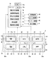
- FIG. 2 is a front view of the operating device shown in FIG.
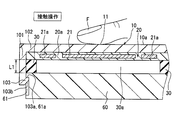
- FIG. 3 is a cross-sectional view taken along line III-III in FIG. 2 and shows a state in which a contact operation is performed.
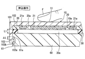
- FIG. 4 is a cross-sectional view showing a state in which the operating device according to the first embodiment is pushed.
- FIG. 5 is a sectional view taken along the line VV in FIG. 2
- FIG. 6 is a cross-sectional view of the operating device according to the second embodiment of the present disclosure.
- FIG. 1 is a perspective view of an instrument panel (instrument panel 2) mounted on a vehicle 1 as viewed from the indoor side.
- a display device 4 and an operation device 5 are attached to a central portion of the instrument panel 2 in the left-right direction of the vehicle.
- the panel 3 is assembled in the opening 2 a formed in the instrument panel 2.
- the display surface of the display device 4 and the front portion of the operation device 5 are exposed from the opening 2 a formed in the panel 3.
- the display device 4 displays the contents set by operating the operation device 5 by the vehicle occupant as a user.
- the operating device 5 includes an operating plate 10, an electrode sheet 20, a pressing elastic member 30, a vibration device 40, an assembly member 60, and a microcomputer (microcomputer 70) which will be described below. It is prepared for.
- the operation plate 10 is a resin member formed in a bottomed cylindrical shape having a cylindrical portion 101 and a bottom portion 102. On the bottom portion 102, a decorative surface 10a that is visually recognized by the user is formed.
- the decorative surface 10 a has a plurality of operation surfaces 11, 12, 13, 14, 15, and 16. On these operation surfaces 11 to 16, characters, symbols, figures and the like representing the setting contents of the operation target are printed.
- the operation target is an air conditioner 80 that air-conditions the interior of the vehicle. For example, activation of the air conditioner 80, air volume setting, temperature setting, and the like are given as specific examples of the setting contents.
- the cylinder portion 101 has a cylindrical shape extending from the periphery of the bottom portion 102 to the opposite side of the decorative surface 10a.
- the extended end portion of the tubular portion 101 is assembled to the resin assembling member 60. This assembly structure will be described in detail later.
- the display device 4 is caused to display an image having contents for notifying which of the plurality of operation surfaces 11 to 16 is the operation surface selected by the contact operation.
- an alarm sound for notifying that is generated.
- the user can push the operation surfaces 11 to 16 with the fingertip F while the setting can be changed, the corresponding setting contents are changed.
- the operation surface 13 is touched, the automatic control setting of the air conditioner 80 can be changed.
- the automatic control ON / OFF setting is switched.
- a command signal for instructing the operation is output from the microcomputer 70 to the air conditioner 80, and the switching of the air-conditioning air outlet and the air volume are automatically controlled.
- the electrode sheet 20 is attached to the surface of the operation plate 10 opposite to the decorative surface 10a with an adhesive.
- the electrode sheet 20 has a plurality of electrodes 21, 22, 23, 24, 25, 26 and a ground electrode 21a.
- the electrodes 21 to 26 and the ground electrode 21a are held on a resin sheet 20a.
- Each of the electrodes 21 to 26 is disposed at a position facing the corresponding operation surface 11 to 16.
- the ground electrode 21a has a shape extending along the outer edges of the electrodes 21 to 26. In FIG. 2, the ground electrode 21a extending along the outer edge of the electrode 21 is shown, and the ground electrodes along the other first electrodes 22 to 26 are not shown.
- the assembly member 60 is disposed on the opposite side of the operation plate 10 with respect to the electrode sheet 20 so as to be separated by a predetermined distance.
- a pressing elastic member 30 is disposed between the electrode sheet 20 and the assembly member 60.
- the predetermined distance corresponds to the thickness dimension L of the pressing elastic member 30.
- the pushing elastic member 30 is made of a material having elasticity such as foaming resin or rubber.
- the pressing elastic member 30 has a shape that extends annularly along the outer periphery of the decorative surface 10a and has an opening 30a inside the annular shape.
- the shape and position of the pushing elastic member 30 are set so that the operation surfaces 11 to 16 are positioned in the opening 30a when viewed from the decorative surface 10a side (operation side) with respect to the operation plate 10. That is, it can be said that the pushing elastic member 30 is arranged outside the region overlapping the operation surface 11 when viewed from the direction of the pushing operation.
- the electrode sheet 20 and the pressing elastic member 30 are stacked in the extending direction (vertical direction in FIG. 3) of the cylindrical portion 101.
- the electrode sheet 20 and the pressing elastic member 30 are stacked and stored in the storage chamber formed inside the operation plate 10 and the assembly member 60.
- the pushing elastic member 30 is accommodated in a state of being elastically deformed in the stacking direction. Both surfaces of the pressing elastic member 30 are bonded to the electrode sheet 20 and the assembly member 60 with an adhesive.
- Engagement portions 103 having engagement surfaces 103a are formed at a plurality of locations on the extending end of the cylinder portion 101.
- An engagement hole 61 into which the engagement portion 103 is fitted is formed in a portion of the side surface of the assembly member 60 facing the engagement portion 103.
- the engaging surface 103 a of the engaging portion 103 and the engaged surface 61 a of the engaging hole 61 are engaged against the elastic force of the pressing elastic member 30, thereby 103 is prevented from coming out of the engagement hole 61.
- the operation plate 10 is stacked on the assembly member 60 with the tapered surface 103 b of the engagement portion 103 pressed against the corner of the assembly member 60. Press in the direction.
- the cylindrical portion 101 is elastically deformed in a direction in which the opening of the operation plate 10 is expanded in a predetermined direction, and the engaging portion 103 is fitted into the engaging hole 61.
- FIG. 3 shows a state where the user touches the operation surface 11 with the fingertip F (operation body), that is, a contact operation.
- the engagement surfaces 103a and 61a remain in the initial state where they are in contact with each other.
- a pressing operation is performed to push the fingertip F that is in contact operation in a direction perpendicular to the decorative surface 10a, that is, in the stacking direction, as shown in FIG. And move relatively to the back side in the pushing direction.
- the operation plate 10 is pushed in while further elastically deforming the pushing elastic member 30, the engaging surface 103a is separated from the engaged surface 61a, and the engaging portion 103 moves in the engaging hole 61.
- FIG. 3 shows a state where the user touches the operation surface 11 with the fingertip F (operation body), that is, a contact operation.
- the engagement surfaces 103a and 61a remain in the initial state where they are in contact with each other.
- the separation distance between the engaging surface 103a and the engaged surface 61a corresponds to the pressing amount ⁇ L by the pressing operation.
- the difference between the thickness dimension L of the pressing elastic member 30 at the time of the contact operation and the thickness dimension L of the pressing elastic member 30 at the time of the pressing operation is a deformation amount by which the pressing elastic member 30 is elastically deformed by the pressing operation.
- the capacitance C1 formed between the electrodes 21 to 26 and the fingertip F changes. Further, when the pushing operation is performed, the capacitance C2 formed between the movable yoke 41 and the fixed yoke 42 changes.
- the vibration device 40 includes a movable yoke 41, a fixed yoke 42, an excitation coil 43, and a vibration elastic member 44.
- the exciting coil 43 generates a magnetic flux when energized.
- the movable yoke 41 and the fixed yoke 42 form a magnetic circuit that guides a magnetic flux generated by energizing the exciting coil 43. Thereby, the magnetic force attracted to the fixed yoke 42 acts on the movable yoke 41.
- the movable yoke 41 is formed in a circular plate shape when viewed from the direction of the pushing operation (see FIG. 2).
- the fixed yoke 42 has a main body portion 42a and a disc portion 42b.
- the main body 42 a has a cylindrical shape around which the exciting coil 43 is wound, and a predetermined gap is formed between the main body 42 a and the movable yoke 41. This gap becomes smaller when a pushing operation is performed.
- the disc part 42b is a plate-like shape that extends in parallel to the movable yoke 41 from the end of the main body part 42a opposite to the movable yoke 41, and overlaps the movable yoke 41 when viewed from the direction of the pushing operation. It is arranged at a position and is a circle having the same diameter as the movable yoke 41.
- the vibration elastic member 44 is a coil spring that compressively deforms in the stacking direction.
- One end of the vibration elastic member 44 is attached to the operation plate 10, and the other end is attached to the assembly member 60.
- the movable yoke 41 is attached to the operation plate 10, and the fixed yoke 42 is attached to the assembly member 60. Therefore, when the exciting coil 43 is energized temporarily, the movable yoke 41 is attracted to the fixed yoke 42, and the operation plate 10 approaches the assembly member 60 so as to reduce the thickness dimension L of the pushing elastic member 30. In other words, the operation plate 10 moves so as to approach the assembly member 60 against the elastic force of the vibration elastic member 44 and the pushing elastic member 30.
- the vibration elastic member 44 is initially deformed when the operation plate 10 is moved by the magnetic force.
- the operation plate 10 is pushed back to the original position by the elastic force of the vibration elastic member 44 that is initially deformed. Thereafter, the operation plate 10 vibrates in the stacking direction by the elastic force of the vibration elastic member 44 while the amplitude is attenuated.
- the exciting coil 43 is connected to the positive voltage harness H1, and the other end of the exciting coil 43 is connected to the ground harness H2.
- the exciting coil 43 is energized through the positive voltage harness H1.
- the movable yoke 41 is connected to a detection harness H3 that applies a detection voltage. Through this detection harness H3, a detection voltage is constantly applied to the movable yoke 41 during the operation period of the operating device 5.
- the detection voltage is set to a value smaller than the voltage applied to the exciting coil 43.
- the electrostatic gap formed between the fixed yoke 42 and the movable yoke 41 is reduced because the gap formed between the fixed yoke 42 and the movable yoke 41 is reduced.
- the capacity C2 changes.
- the microcomputer 70 includes a central processing unit (CPU 70a) and a storage device (memory 70b).
- the CPU 70a executes arithmetic processing in accordance with a program stored in the memory 70b, whereby an electrode detection device 71, a detection device 72, a contact determination device 73, an indentation determination device 74, a vibration control device 75, and a voltage application described below are performed. It functions as a device 76 (see FIG. 2).
- the electrode detection device 71 repeats charging / discharging of the electrodes 21 to 26 forming the above-described capacitance C1, and counts the number of times of charging / discharging until a predetermined condition is satisfied.
- a predetermined voltage for example, 1 V
- the ground electrode 21a is connected to a ground terminal (not shown).
- the ground electrode 21a exhibits a function of suppressing a signal corresponding to the capacitance C1 of the electrodes 21 to 26 from being affected by noise.
- the contact determination device 73 determines that a contact operation is being performed when the contact detection value is equal to or greater than the threshold value TH1 and the state continues for a predetermined time or more.
- the microcomputer 70 changes the setting content of the air conditioner 80 associated with the operation surface 11 corresponding to the contact operation to be changeable.
- Specific examples of the setting include the above-described activation of the air conditioner, air volume setting, temperature setting, and the like.
- the microcomputer 70 outputs a command signal corresponding to the above setting to the air conditioner 80 to control the operation of the air conditioner 80. If it determines with pushing operation apparatus 74 mentioned later having performed pushing operation, the microcomputer 70 will perform setting change about the setting content selected by contact operation. For example, the air volume setting or temperature setting of the air conditioner is changed.
- the operating device 5 can function the audio device 81 and the navigation device 82 in addition to the air conditioner 80 as an operation target.
- the microcomputer 70 outputs a command signal corresponding to the setting content by the operation device 5 to the audio device 81 and the navigation device 82 and controls the operation of these devices 81 and 82.
- the voltage application device 76 applies a detection voltage to the movable yoke 41.
- This detection voltage is set to a value that is the same as a predetermined voltage (for example, 1 V) applied to the electrodes 21 to 26.
- the voltage application device 76 continuously applies the detection voltage at least during the period when the contact operation is performed.
- the capacitance C2 described above changes, and a change occurs in the detection voltage applied to the movable yoke 41 along with the change.
- the amount of change in the detected voltage is a value representing the capacitance C2 (indent detection value). Specifically, the gap becomes smaller as the pushing amount increases. Therefore, the capacitance C2 increases and the indent detection value increases.
- Detecting device 72 is a device that detects the amount of indentation caused by the indentation operation. Specifically, it detects the amount of change in the detected voltage and outputs the amount of change as the indentation detection value.
- the indentation determination device 74 determines that an indentation operation has been performed when the indentation detection value is equal to or greater than the threshold value TH2 and the state continues for a predetermined time or more.
- the vibration control device 75 energizes the excitation coil 43 for a predetermined time when it is determined by the push determination device 74 that the push operation has been performed.
- the amount of pushing used for the judgment of the pushing judgment device 74 is detected by detecting the change in the capacitance formed between the movable yoke 41 and the fixed yoke 42. Therefore, when detecting the change in capacitance formed between the pair of electrodes and detecting the push amount, it is not necessary to provide a dedicated electrode for detecting the push amount, and the movable yoke of the vibration device 40 is provided. 41 and the fixed yoke 42 can function as the electrodes. Therefore, a vibration notification function can be provided while suppressing an increase in the number of parts as much as a dedicated electrode can be dispensed with.
- a voltage application device 76 that applies a detection voltage to the movable yoke 41 is provided. According to this, the degree to which the change of the detection voltage is influenced by the excitation coil 43 can be reduced as compared with the case where the detection voltage is applied to the fixed yoke 42 contrary to the present embodiment, for example. Therefore, the detection accuracy can be improved when detecting a change in capacitance formed between the movable yoke 41 and the fixed yoke 42.
- the vibration device 40 includes a vibration elastic member 44 that vibrates by being initially deformed by a magnetic force generated by energizing the excitation coil 43. According to this, if the excitation coil 43 is energized temporarily, the operation plate 10 can be vibrated by the vibration of the vibration elastic member 44 after the energization is completed. Therefore, the power consumption can be reduced and the control of energization can be simplified as compared with the case where the excitation coil 43 is vibrated by repeatedly turning on and off the energization several times.
- the voltage application device 76 applies a detection voltage to the movable yoke 41, and the detection device 72 detects the push-in amount based on the change amount of the detection voltage.
- the voltage application device 76 according to the present embodiment shown in FIG. 6 applies a detection voltage to the excitation coil 43, and the detection device 72 detects the push-in amount based on the change amount of the detection voltage.
- the detection harness H3 shown in FIG. 5 is eliminated, and the voltage application device 76 applies the detection voltage to the excitation coil 43 through the positive voltage harness H1.
- the detection voltage is set to a value smaller than the voltage applied to the exciting coil 43, and is set to the same value as a predetermined voltage (for example, 1 V) applied to the electrodes 21 to 26.
- the voltage application device 76 constantly applies the detection voltage to the excitation coil 43 during the operation period of the operation device 5 except during the period in which the vibration device 40 is vibrated.
- the amount of change in the detection voltage is a value (indent detection value) representing the inductance.
- Detecting device 72, indentation determining device 74, and vibration control device 75 function in the same manner as in the first embodiment.
- the detection device 72 outputs the change amount of the detection voltage as a push detection value.
- the indentation determination device 74 determines that an indentation operation has been performed when the indentation detection value is equal to or greater than the threshold value TH2 and the state continues for a predetermined time or more.
- the vibration control device 75 energizes the excitation coil 43 for a predetermined time when it is determined by the push determination device 74 that the push operation has been performed.
- the push amount used for the determination of the push determination device 74 is detected by detecting a change in the inductance of the exciting coil 43 included in the vibration device 40. Therefore, it is not necessary to provide a dedicated coil for detecting the pushing amount when detecting the inductance change of the coil to detect the pushing amount, and the exciting coil 43 of the vibration device 40 is used.
- a vibration notification function can be provided while suppressing the increase.
- the detection voltage is applied to the excitation coil 43 using harnesses H1 and H2 that supply vibration power to the excitation coil 43.
- the vibration power supply harnesses H1 and H2 are shared with the detection voltage application harness. According to this, the number of harnesses can be reduced as compared with the case where a dedicated harness for applying the detection voltage is provided.
- the fixed yoke 42 is grounded to stabilize the fixed yoke 42 at the ground potential.
- grounding the fixed yoke 42 may be eliminated and the fixed yoke 42 may be set to a floating potential.
- the vibration device 40 includes the vibration elastic member 44, and the magnetic force generated by energizing the excitation coil 43 is used for initial deformation of the vibration elastic member 44. 44 vibrates the operation plate 10. On the other hand, the vibration elastic member 44 is abolished and the energization of the excitation coil 43 is continuously turned on and off repeatedly, whereby the movable yoke 41 is vibrated by the magnetic force change, and the operation plate 10 is vibrated by the vibration of the movable yoke 41 May be vibrated.
- the voltage application device 76 applies a detection voltage to the movable yoke 41, thereby detecting a change in the capacitance C ⁇ b> 2 formed between the movable yoke 41 and the fixed yoke 42. is doing.
- a change in the capacitance C2 may be detected by applying a detection voltage to the fixed yoke 42.
- both the elastic member 44 for vibration and the elastic member 30 for pushing are provided.
- one of the elastic member 44 for vibration and the elastic member 30 for pushing may be abolished, and it may be used by the other.
- the elastic member 44 for vibration is abolished, the pushing elastic member 30 is initially deformed by the magnetic force generated by energizing the exciting coil 43, and the pushing elastic member 30 vibrates the operation plate 10 after the energization.
- the pushing elastic member 30 is eliminated, and the operation plate 10 after the pushing operation is moved to the original position, that is, the engaging surface 103a is engaged with the engaged surface 61a by the elastic force of the vibrating elastic member 44 elastically deformed by the pushing force. You may push back to the position which contacts.
- the electrodes 21 to 26 are held inside the sheet 20a.
- the electrodes 21 to 26 may be printed on the surface of the sheet 20a.
- the electrodes 21 to 26 used for the determination by the contact determination device 73 are used for the determination by the indentation determination device 74.
- this indication is applicable also to the operating device 5 which is not provided with the function of the contact determination apparatus 73.
- the operation plate 10 is assembled to the assembly member 60 so as to be movable in the pushing operation direction. Specifically, the engaging portion 103 moves in the engaging hole 61.
- the operation plate 10 may be assembled to the assembly member 60 in a state in which it cannot move, and the operation plate 10 may be elastically deformed and bent by the pushing operation, and the amount of bending may be set as the pushing operation amount.
- the user's fingertip F is operated while being in contact with the operation surfaces 11 to 16, and the fingertip F is used as the operating body.
- the user may hold a pen-shaped operation member and operate it by bringing the operation member into contact with the operation surfaces 11 to 16.
- an operation member other than the human body functions as the operation body.
- the gloves function as an operating body.
Landscapes
- Engineering & Computer Science (AREA)
- General Engineering & Computer Science (AREA)
- Theoretical Computer Science (AREA)
- Human Computer Interaction (AREA)
- Physics & Mathematics (AREA)
- General Physics & Mathematics (AREA)
- User Interface Of Digital Computer (AREA)
- Switches That Are Operated By Magnetic Or Electric Fields (AREA)
- Push-Button Switches (AREA)
- Input From Keyboards Or The Like (AREA)
Abstract
操作装置は、操作体(F)により押込操作される操作面(11、12、13、14、15、16)が設けられた操作プレート(10)と、磁束を導く磁気回路を形成する可動ヨーク(41)および固定ヨーク(42)と、前記磁束を生じさせる励磁コイル(43)とを有し、前記励磁コイルへの通電により生じた磁力で前記操作プレートを振動させる振動装置(40)と、前記押込操作による押込量を検出する検出装置(72)と、前記検出装置により検出された押込量に基づき、前記押込操作が為されたか否かを判定する押込判定装置(74)と、前記押込操作が為されたと前記押込判定装置が判定したことを条件として、前記励磁コイルへ通電する振動制御装置(75)と、を備える。前記検出装置は、前記可動ヨークと前記固定ヨークの間で形成される静電容量の変化を検出することで、前記押込量を検出する。
Description
本出願は、2015年7月21日に出願された日本特許出願番号2015-144131号に基づくもので、ここにその記載内容を援用する。
本開示は、操作プレートの操作面を押し込んで操作する操作装置に関する。
特許文献1には、操作者が指先(操作体)で操作プレートの操作面を接触して操作する操作装置に、操作プレートを振動させる振動装置を備えさせている。そして、接触操作が為されたことが検知された場合に振動装置を作動させて、接触操作が検知された旨をユーザに報知する技術が開示されている。
上記従来の操作装置が接触操作するものであるのに対し、本発明者らは、操作面を押し込んで操作(押込操作)する操作装置について、振動報知の機能を付加させることを検討した。例えば、押込操作による押込量が所定量以上であると検知された場合に、振動装置を作動させて、押込操作が検知された旨をユーザに報知する。
しかしながら、このように振動報知の機能を付与させると、操作装置の部品点数増大を招く。
本開示の目的は、部品点数の増大を抑制しつつ振動報知機能を付与させることを可能にした操作装置を提供することにある。
本開示の第一の態様に係る操作装置は、操作体により押込操作される操作面が設けられた操作プレートと、磁束を導く磁気回路を形成する可動ヨークおよび固定ヨークと、前記磁束を生じさせる励磁コイルとを有し、前記励磁コイルへの通電により生じた磁力で前記操作プレートを振動させる振動装置と、前記押込操作による押込量を検出する検出装置と、前記検出装置により検出された押込量に基づき、前記押込操作が為されたか否かを判定する押込判定装置と、前記押込操作が為されたと前記押込判定装置が判定したことを条件として、前記励磁コイルへ通電する振動制御装置と、を備える。前記検出装置は、前記可動ヨークと前記固定ヨークの間で形成される静電容量の変化を検出することで、前記押込量を検出する。
上記の操作装置によれば、押込操作を行うと、振動装置が有する可動ヨークと固定ヨークの間で形成される静電容量が変化することに着目して為されたものであり、上記静電容量の変化を検出することで、押込判定装置の判定に用いる押込量を検出する。そのため、一対の電極間で形成される静電容量の変化を検出して押込量を検出するにあたり、押込量を検出する専用の電極を備えさせることを不要にでき、振動装置が有する可動ヨークと固定ヨークを上記電極として機能させることができる。よって、専用の電極を不要にできる分、部品点数の増大を抑制しつつ振動報知機能を付与できる。
本開示の第二の態様に係る操作装置は、操作体により押込操作される操作面が設けられた操作プレートと、磁束を導く磁気回路を形成する可動ヨークおよび固定ヨークと、前記磁束を生じさせる励磁コイルとを有し、前記励磁コイルへの通電により生じた磁力で前記操作プレートを振動させる振動装置と、前記押込操作による押込量を検出する検出装置と、前記検出装置により検出された押込量に基づき、前記押込操作が為されたか否かを判定する押込判定装置と、前記押込操作が為されたと前記押込判定装置が判定したことを条件として、前記励磁コイルへ通電する振動制御装置と、前記励磁コイルへ検出電圧を印加する電圧印加装置と、を備える。前記検出装置は、前記励磁コイルのインダクタンスの変化を前記検出電圧の印加時に検出することで、前記押込量を検出する。
上記の操作装置によれば、押込操作を行うと、振動装置が有する励磁コイルのインダクタンスが変化することに着目して為されたものであり、上記インダクタンスの変化を検出することで、押込判定装置の判定に用いる押込量を検出する。そのため、コイルのインダクタンス変化を検出して押込量を検出するにあたり、押込量を検出する専用のコイルを備えさせることを不要にでき、振動装置が有する励磁コイルを利用するので、部品点数の増大を抑制しつつ振動報知機能を付与できる。
本開示についての上記目的およびその他の目的、特徴や利点は、添付の図面を参照しながら下記の詳細な記述により、より明確になる。その図面は、
図1は、本開示の第1実施形態に係る操作装置の、車両搭載位置を示す斜視図であり、
図2は、図1に示す操作装置の正面図であり、
図3は、図2のIII-III線に沿う断面図であって、接触操作されている状態を示す図であり、
図4は、第1実施形態に係る操作装置の、押込操作されている状態を示す断面図であり、
図5は、図2のV-V線に沿う断面図であり、及び、
図6は、本開示の第2実施形態に係る操作装置の断面図である。
以下、図面を参照しながら本開示に係る操作装置を実施するための複数の形態を説明する。各形態において、先行する形態で説明した事項に対応する部分には同一の参照符号を付して重複する説明を省略する場合がある。各形態において、構成の一部のみを説明している場合は、構成の他の部分については先行して説明した他の形態を参照し適用することができる。
(第1実施形態)
図1は、車両1に搭載されたインストルメントパネル(インパネ2)を室内側から見た斜視図である。インパネ2のうち車両左右方向の中央部分には、表示装置4および操作装置5が取り付けられている。具体的には、インパネ2に形成された開口部2aにパネル3が組み付けられている。そして、パネル3に形成された開口部2aから、表示装置4の表示面および操作装置5の正面部分が露出している。表示装置4には、ユーザである車両乗員が操作装置5を操作して設定した内容が表示される。
図1は、車両1に搭載されたインストルメントパネル(インパネ2)を室内側から見た斜視図である。インパネ2のうち車両左右方向の中央部分には、表示装置4および操作装置5が取り付けられている。具体的には、インパネ2に形成された開口部2aにパネル3が組み付けられている。そして、パネル3に形成された開口部2aから、表示装置4の表示面および操作装置5の正面部分が露出している。表示装置4には、ユーザである車両乗員が操作装置5を操作して設定した内容が表示される。
図2および図3に示すように、操作装置5は、以下に説明する操作プレート10、電極シート20、押込用弾性部材30、振動装置40、組付部材60、およびマイクロコンピュータ(マイコン70)を備えて構成されている。
操作プレート10は、筒部101および底部102を有する有底筒状に形成された、樹脂製の部材である。底部102には、ユーザに視認される装飾面10aが形成されている。装飾面10aは、複数の操作面11、12、13、14、15、16を有している。これらの操作面11~16には、操作対象の設定内容を表した文字や記号、図形等が印刷されている。図1に示す例では、操作対象は、車室内を空調する空調装置80であり、例えば、空調装置80の起動、風量設定、温度設定等が上記設定内容の具体例として挙げられる。筒部101は、底部102の周縁から装飾面10aの反対側に延びる筒形状である。筒部101の延出端部は、樹脂製の組付部材60に組み付けられる。この組付け構造については、後に詳述する。
ユーザが指先Fで操作面11~16を触れる接触操作をすると、対応する設定内容が設定変更可能な状態になる。例えば、複数の操作面11~16のうち接触操作により選択された操作面がいずれであるかを報知する内容の画像を、表示装置4に表示させる。接触操作が為されて設定変更可能な状態になると、その旨を報知するアラーム音を発生させたりする。設定変更可能な状態で、ユーザが指先Fで操作面11~16をさらに押し込む押込操作をすると、対応する設定内容の変更が実行される。例えば、操作面13が接触操作されると、空調装置80の自動制御の設定が変更可能になり、この状態で操作面13が押込操作されると、自動制御のオンオフ設定が切り替わる。例えば自動制御がオン設定に切り替わると、その作動を指令する指令信号がマイコン70から空調装置80へ出力され、空調風の吹出口の切り替えや風量等が自動制御される。
操作プレート10のうち装飾面10aの反対側の面には、電極シート20が接着剤で貼り付けられている。電極シート20は、複数の電極21、22、23、24、25、26およびグランド電極21aを有する。これらの電極21~26およびグランド電極21aは、樹脂製のシート20aに保持されている。電極21~26の各々は、対応する操作面11~16に対向する位置に配置されている。グランド電極21aは、電極21~26の外縁に沿って延びる形状である。図2では、電極21の外縁に沿って延びるグランド電極21aを図示しており、他の第1電極22~26に沿うグランド電極については図示を省略している。
電極シート20に対して操作プレート10の反対側には、所定距離だけ離間して配置された組付部材60が配置されている。電極シート20と組付部材60の間には、押込用弾性部材30が配置されている。上記所定距離は、押込用弾性部材30の厚み寸法Lに相当する。押込用弾性部材30は、発泡性樹脂やゴム等の弾性を有する材質で形成されている。
押込用弾性部材30は、装飾面10aの外周に沿って環状に延び、環状の内側に開口部30aを有する形状である。操作プレート10に対して装飾面10aの側(操作側)から見て、操作面11~16が開口部30aに位置するよう、押込用弾性部材30の形状と位置が設定されている。つまり、押込用弾性部材30は、押込操作の方向から見て操作面11と重複する領域の外に配置されていると言える。
操作プレート10の底部102と組付部材60の間において、電極シート20および押込用弾性部材30は、筒部101の延出方向(図3の上下方向)に積層して配置されている。換言すれば、操作プレート10および組付部材60の内部に形成された収容室に、電極シート20および押込用弾性部材30が積層して収容されている。押込用弾性部材30は、積層方向に弾性変形した状態で収容されている。押込用弾性部材30の両面は、電極シート20および組付部材60に接着剤で接着されている。
次に、操作プレート10と組付部材60の組付け構造について詳細に説明する。筒部101の延出端の複数箇所には、係合面103aを有する係合部103が形成されている。組付部材60の側面のうち係合部103に対向する部分には、係合部103が嵌り込む係合穴61が形成されている。図3の状態では、押込用弾性部材30の弾性力に抗して、係合部103の係合面103aと係合穴61の被係合面61aとが係合することにより、係合部103が係合穴61から抜け出ることを防止している。
なお、操作プレート10を組付部材60に組付ける作業においては、係合部103のテーパ面103bを組付部材60の角部に押し当てた状態で、操作プレート10を組付部材60に積層方向へ押し付ける。これにより、操作プレート10の開口部が所定方向に押し広げられる向きに筒部101が弾性変形して、係合部103が係合穴61に嵌り込む。
図3は、ユーザが指先F(操作体)を操作面11に接触させた状態、つまり接触操作した状態を示す。この状態では、係合面103a、61aが互いに当接した初期状態のままとなっている。接触操作している指先Fを装飾面10aに対して垂直方向、つまり積層方向の奥側へ押し込む押込操作が為されると、図4に示すように、操作プレート10が組付部材60に対して、押込方向奥側へ相対的に移動する。具体的には、押込用弾性部材30をさらに弾性変形させながら操作プレート10を押し込むと、係合面103aが被係合面61aから離れて、係合部103が係合穴61内を移動し、図4の状態になる。つまり、係合面103aと被係合面61aとの離間距離が、押込操作による押込量ΔLに相当する。接触操作時の押込用弾性部材30の厚み寸法Lと、押込操作時の押込用弾性部材30の厚み寸法Lとの差分が、押込操作により押込用弾性部材30が弾性変形した変形量である。
接触操作が為されると、電極21~26と指先Fとの間で形成される静電容量C1が変化する。また、押込操作が為されると、可動ヨーク41と固定ヨーク42との間で形成される静電容量C2が変化する。
図5に示すように、振動装置40は、可動ヨーク41、固定ヨーク42、励磁コイル43および振動用弾性部材44を有する。励磁コイル43は通電により磁束を生じさせる。可動ヨーク41および固定ヨーク42は、励磁コイル43への通電により生じた磁束を導く磁気回路を形成する。これにより、可動ヨーク41には、固定ヨーク42へ吸引される磁力が作用する。
可動ヨーク41は、押込操作の方向から見て円形の板状に形成されている(図2参照)。固定ヨーク42は、本体部42aおよび円板部42bを有する。本体部42aは、励磁コイル43が巻き回される円柱形状であり、可動ヨーク41との間に所定のギャップが形成されている。このギャップは、押込操作が為されると小さくなる。円板部42bは、本体部42aのうち可動ヨーク41の反対側の端部から、可動ヨーク41に対して平行に拡がる板状であり、かつ、押込操作の方向から見て可動ヨーク41と重なる位置に配置され、かつ、可動ヨーク41と同じ直径の円形である。
振動用弾性部材44は、積層方向に圧縮変形するコイルばねである。振動用弾性部材44の一端は操作プレート10に取り付けられ、他端は組付部材60に取り付けられている。可動ヨーク41は操作プレート10に取り付けられ、固定ヨーク42は組付部材60に取り付けられている。したがって、励磁コイル43に一時的に通電すると、可動ヨーク41が固定ヨーク42に吸引され、押込用弾性部材30の厚み寸法Lを小さくするように、操作プレート10が組付部材60に近づく。換言すれば、振動用弾性部材44および押込用弾性部材30の弾性力に抗して、操作プレート10が組付部材60に近づくように移動する。振動用弾性部材44は、上記磁力により操作プレート10が移動することで初期変形する。そして、励磁コイル43への一時的な通電が停止されると、初期変形した振動用弾性部材44の弾性力により操作プレート10が元の位置へ向けて押し戻される。その後、操作プレート10は振幅を減衰させながら振動用弾性部材44の弾性力により積層方向に振動する。
励磁コイル43の一端は正電圧ハーネスH1に接続され、励磁コイル43の他端は接地ハーネスH2に接続されている。これらの正電圧ハーネスH1を通じて励磁コイル43への通電が為される。また、可動ヨーク41には検出電圧を印加する検出用ハーネスH3が接続されている。この検出用ハーネスH3を通じて、可動ヨーク41には検出電圧が、操作装置5の作動期間中に常時印加されている。検出電圧は、励磁コイル43へ印加する電圧よりも小さい値に設定されている。
上述した押込操作が為されると、固定ヨーク42と可動ヨーク41との間に形成されるギャップが小さくなることに起因して、固定ヨーク42と可動ヨーク41との間で形成される静電容量C2が変化する。
マイコン70は、中央演算処理装置(CPU70a)および記憶装置(メモリ70b)を備える。CPU70aは、メモリ70bに記憶されたプログラムにしたがって演算処理を実行することにより、以下に説明する電極検出装置71、検出装置72、接触判定装置73、押込判定装置74、振動制御装置75、電圧印加装置76として機能する(図2参照)。
電極検出装置71は、先述した静電容量C1を形成する電極21~26に対して充放電を繰り返すとともに、所定条件を満たすまでの充放電回数をカウントする。電極21~26と指先Fとの間で生じる静電容量C1が大きいほど、上記カウント値は大きい値になる。したがって、このカウント値が静電容量C1を表わす値(接触検出値)である。なお、上記充電時には、電極21~26に所定の電圧(例えば1V)を印加する。グランド電極21aは、図示しないグランド端子に接続されている。グランド電極21aは、電極21~26の静電容量C1に応じた信号がノイズの影響を受けることを抑制する機能を発揮する。
接触判定装置73は、接触検出値が閾値TH1以上であり、かつ、その状態が所定時間以上継続した場合に、接触操作が為されていると判定する。接触判定装置73により接触操作が為されていると判定されると、マイコン70は、接触操作に該当する操作面11に関連付けられた、空調装置80の設定内容を変更可能な状態にする。上記設定の具体例としては、先述した空調装置の起動、風量設定、温度設定等が挙げられる。マイコン70は、上記設定に応じた指令信号を空調装置80に出力し、空調装置80の作動を制御する。後述する押込判定装置74により押込操作が為されていると判定されると、マイコン70は、接触操作により選択された設定内容について、設定変更を実行する。例えば空調装置の風量設定や温度設定を変更する。
なお、操作装置5は、空調装置80の他にも、オーディオ装置81やナビゲート装置82を操作対象として機能させることもできる。この場合、マイコン70は、操作装置5による設定内容に応じた指令信号をオーディオ装置81やナビゲート装置82に出力し、これらの装置81、82の作動を制御する。
電圧印加装置76は、可動ヨーク41へ検出電圧を印加する。この検出電圧は、電極21~26に印加する所定の電圧(例えば1V)と同じ大きさの値に設定されている。電圧印加装置76は、少なくとも接触操作が為されている期間中、検出電圧を継続して印加する。押込操作が為されると先述した静電容量C2が変化し、その変化に伴い、可動ヨーク41に印加していた検出電圧に変化が生じる。この検出電圧の変化量が静電容量C2を表わす値(押込検出値)である。具体的には、押込量が大きいほどギャップが小さくなる。よって、静電容量C2が大きくなり、押込検出値が大きくなる。
検出装置72は、押込操作による押込量を検出する装置であり、具体的には、検出電圧の変化量を検出し、その変化量を押込検出値として出力する。押込判定装置74は、押込検出値が閾値TH2以上であり、かつ、その状態が所定時間以上継続した場合に、押込操作が為されていると判定する。振動制御装置75は、押込判定装置74により押込操作が為されたと判定された場合に、励磁コイル43へ所定時間だけ通電する。
以上により、本実施形態では、可動ヨーク41と固定ヨーク42の間で形成される静電容量の変化を検出することで、押込判定装置74の判定に用いる押込量を検出する。そのため、一対の電極間で形成される静電容量の変化を検出して押込量を検出するにあたり、押込量を検出する専用の電極を備えさせることを不要にでき、振動装置40が有する可動ヨーク41と固定ヨーク42を上記電極として機能させることができる。よって、専用の電極を不要にできる分、部品点数の増大を抑制しつつ振動報知機能を付与できる。
さらに本実施形態では、可動ヨーク41へ検出電圧を印加する電圧印加装置76を備える。これによれば、例えば本実施形態に反して固定ヨーク42へ検出電圧を印加する場合に比べて、検出電圧の変化が励磁コイル43の影響を受ける度合いを小さくできる。そのため、可動ヨーク41と固定ヨーク42の間で形成される静電容量の変化を検出するにあたり、その検出精度を向上できる。
さらに本実施形態では、振動装置40は、励磁コイル43への通電により生じた磁力で初期変形して振動する振動用弾性部材44を有する。これによれば、励磁コイル43へ一時的に通電すれば、その通電終了後は振動用弾性部材44の振動で操作プレート10を振動させることができる。よって、励磁コイル43への通電オンオフを複数回繰返し行うことで振動させる場合に比べて、電力消費量を低減でき、かつ、通電の制御を簡素にできる。
(第2実施形態)
上記第1実施形態に係る電圧印加装置76は、可動ヨーク41へ検出電圧を印加し、検出装置72は、その検出電圧の変化量に基づき押込量を検出する。これに対し、図6に示す本実施形態に係る電圧印加装置76は、励磁コイル43へ検出電圧を印加し、検出装置72は、その検出電圧の変化量に基づき押込量を検出する。
上記第1実施形態に係る電圧印加装置76は、可動ヨーク41へ検出電圧を印加し、検出装置72は、その検出電圧の変化量に基づき押込量を検出する。これに対し、図6に示す本実施形態に係る電圧印加装置76は、励磁コイル43へ検出電圧を印加し、検出装置72は、その検出電圧の変化量に基づき押込量を検出する。
具体的には、本実施形態では図5に示す検出用ハーネスH3を廃止し、電圧印加装置76は、正電圧ハーネスH1を通じて検出電圧を励磁コイル43へ印加する。検出電圧は、励磁コイル43へ印加する電圧よりも小さい値に設定されており、かつ、電極21~26に印加する所定の電圧(例えば1V)と同じ大きさの値に設定されている。電圧印加装置76は、操作装置5の作動期間中に、振動装置40を振動させる期間を除き、励磁コイル43へ検出電圧を常時印加させる。
このように励磁コイル43へ検出電圧を印加させると、励磁コイル43の周囲に磁場が生じる。この状態で押込操作が為されると、上記磁場に変化が生じるので、その磁場変化に起因して、励磁コイル43のインダクタンスが変化し、その変化に伴い、励磁コイル43に印加していた検出電圧に変化が生じる。この検出電圧の変化量が上記インダクタンスを表わす値(押込検出値)である。
検出装置72、押込判定装置74および振動制御装置75は、上記第1実施形態と同様に機能する。すなわち、検出装置72は、検出電圧の変化量を押込検出値として出力する。押込判定装置74は、押込検出値が閾値TH2以上であり、かつ、その状態が所定時間以上継続した場合に、押込操作が為されていると判定する。振動制御装置75は、押込判定装置74により押込操作が為されたと判定された場合に、励磁コイル43へ所定時間だけ通電する。
以上により、本実施形態では、振動装置40が有する励磁コイル43のインダクタンスの変化を検出することで、押込判定装置74の判定に用いる押込量を検出する。そのため、コイルのインダクタンス変化を検出して押込量を検出するにあたり、押込量を検出する専用のコイルを備えさせることを不要にでき、振動装置40が有する励磁コイル43を利用するので、部品点数の増大を抑制しつつ振動報知機能を付与できる。
さらに本実施形態では、励磁コイル43へ振動電力を供給するハーネスH1、H2を利用して、検出電圧を励磁コイル43へ印加する。換言すれば、振動電力供給用のハーネスH1、H2を、検出電圧印加用のハーネスと共用させる。これによれば、検出電圧を印加する専用のハーネスを備えさせる場合に比べて、ハーネスの本数を低減できる。
(他の実施形態)
以上、発明の好ましい実施形態について説明したが、発明は上述した実施形態に何ら制限されることなく、以下に例示するように種々変形して実施することが可能である。各実施形態で具体的に組合せが可能であることを明示している部分同士の組合せばかりではなく、特に組合せに支障が生じなければ、明示してなくとも実施形態同士を部分的に組み合せることも可能である。
以上、発明の好ましい実施形態について説明したが、発明は上述した実施形態に何ら制限されることなく、以下に例示するように種々変形して実施することが可能である。各実施形態で具体的に組合せが可能であることを明示している部分同士の組合せばかりではなく、特に組合せに支障が生じなければ、明示してなくとも実施形態同士を部分的に組み合せることも可能である。
上記第1実施形態および第2実施形態では、固定ヨーク42を接地させることで、固定ヨーク42を接地電位に安定させている。これに対し、固定ヨーク42を接地させることを廃止して、固定ヨーク42をフローティング電位にしてもよい。
上記各実施形態の振動装置40は振動用弾性部材44を有し、励磁コイル43への通電により生じた磁力は、振動用弾性部材44の初期変形に用いられ、その通電後は振動用弾性部材44が操作プレート10を振動させる。これに対し、振動用弾性部材44を廃止し、励磁コイル43への通電のオンオフを連続して繰返し実施することで、磁力変化により可動ヨーク41を振動させ、可動ヨーク41の振動により操作プレート10を振動させてもよい。
上記第1実施形態に係る電圧印加装置76は、可動ヨーク41へ検出電圧を印加しており、これにより、可動ヨーク41と固定ヨーク42との間で形成される静電容量C2の変化を検出している。これに対し、固定ヨーク42へ検出電圧を印加して、上記静電容量C2の変化を検出してもよい。
上記各実施形態では、振動用弾性部材44および押込用弾性部材30の両方を備える。これに対し、振動用弾性部材44および押込用弾性部材30の一方を廃止して他方で兼用させてもよい。例えば、振動用弾性部材44を廃止し、励磁コイル43への通電により生じた磁力により押込用弾性部材30を初期変形させ、その通電後は押込用弾性部材30が操作プレート10を振動させる。或いは、押込用弾性部材30を廃止し、押込力により弾性変形した振動用弾性部材44の弾性力で、押込操作後の操作プレート10を元の位置、つまり係合面103aが被係合面61aに接触する位置まで押し戻させてもよい。
図3に示す実施形態では、電極21~26がシート20aの内部に保持された構造である。この構造に替えて、電極21~26がシート20aの表面に印刷された構造であってもよい。
上記第1実施形態では、接触判定装置73の判定に用いる電極21~26を、押込判定装置74の判定に用いている。これに対し、接触判定装置73の機能を備えていない操作装置5にも本開示は適用できる。
上記各実施形態では、押込操作方向に移動可能な状態で操作プレート10が組付部材60に組み付けられている。具体的には、係合部103が係合穴61内を移動する。これに対し、移動不可の状態で操作プレート10を組付部材60に組み付けて、押込操作により操作プレート10が弾性変形して撓み、その撓み量を押込操作量としてもよい。
上記各実施形態では、ユーザの指先Fを操作面11~16に接触させて操作することを想定しており、指先Fを操作体としている。これに対し、例えばペン形状の操作部材をユーザが持ち、その操作部材を操作面11~16に接触させて操作してもよく、この場合には、人体以外の操作部材が操作体として機能する。また、ユーザが手袋をはめた状態で操作面11~16を接触操作した場合には、手袋が操作体として機能する。
本開示は、実施例に準拠して記述されたが、本開示は当該実施例や構造に限定されるものではないと理解される。本開示は、様々な変形例や均等範囲内の変形をも包含する。加えて、様々な組み合わせや形態、さらには、それらに一要素のみ、それ以上、あるいはそれ以下、を含む他の組み合わせや形態をも、本開示の範疇や思想範囲に入るものである。
Claims (4)
- 操作体(F)により押込操作される操作面(11、12、13、14、15、16)が設けられた操作プレート(10)と、
磁束を導く磁気回路を形成する可動ヨーク(41)および固定ヨーク(42)と、前記磁束を生じさせる励磁コイル(43)とを有し、前記励磁コイルへの通電により生じた磁力で前記操作プレートを振動させる振動装置(40)と、
前記押込操作による押込量を検出する検出装置(72)と、
前記検出装置により検出された押込量に基づき、前記押込操作が為されたか否かを判定する押込判定装置(74)と、
前記押込操作が為されたと前記押込判定装置が判定したことを条件として、前記励磁コイルへ通電する振動制御装置(75)と、
を備え、
前記検出装置は、前記可動ヨークと前記固定ヨークの間で形成される静電容量の変化を検出することで、前記押込量を検出する操作装置。 - 前記可動ヨークへ検出電圧を印加する電圧印加装置(76)を備える請求項1に記載の操作装置。
- 操作体(F)により押込操作される操作面(11、12、13、14、15、16)が設けられた操作プレート(10)と、
磁束を導く磁気回路を形成する可動ヨーク(41)および固定ヨーク(42)と、前記磁束を生じさせる励磁コイル(43)とを有し、前記励磁コイルへの通電により生じた磁力で前記操作プレートを振動させる振動装置(40)と、
前記押込操作による押込量を検出する検出装置(72)と、
前記検出装置により検出された押込量に基づき、前記押込操作が為されたか否かを判定する押込判定装置(74)と、
前記押込操作が為されたと前記押込判定装置が判定したことを条件として、前記励磁コイルへ通電する振動制御装置(75)と、
前記励磁コイルへ検出電圧を印加する電圧印加装置(76)と、
を備え、
前記検出装置は、前記励磁コイルのインダクタンスの変化を前記検出電圧の印加時に検出することで、前記押込量を検出する操作装置。 - 前記振動装置は、前記磁力で初期変形して振動する弾性部材(44)を有する請求項1~3のいずれか1つに記載の操作装置。
Priority Applications (1)
| Application Number | Priority Date | Filing Date | Title |
|---|---|---|---|
| US15/741,181 US10241578B2 (en) | 2015-07-21 | 2016-07-05 | Operation apparatus |
Applications Claiming Priority (2)
| Application Number | Priority Date | Filing Date | Title |
|---|---|---|---|
| JP2015144131A JP6292186B2 (ja) | 2015-07-21 | 2015-07-21 | 操作装置 |
| JP2015-144131 | 2015-07-21 |
Publications (1)
| Publication Number | Publication Date |
|---|---|
| WO2017014042A1 true WO2017014042A1 (ja) | 2017-01-26 |
Family
ID=57833940
Family Applications (1)
| Application Number | Title | Priority Date | Filing Date |
|---|---|---|---|
| PCT/JP2016/069844 Ceased WO2017014042A1 (ja) | 2015-07-21 | 2016-07-05 | 操作装置 |
Country Status (3)
| Country | Link |
|---|---|
| US (1) | US10241578B2 (ja) |
| JP (1) | JP6292186B2 (ja) |
| WO (1) | WO2017014042A1 (ja) |
Cited By (2)
| Publication number | Priority date | Publication date | Assignee | Title |
|---|---|---|---|---|
| CN112905041A (zh) * | 2019-12-04 | 2021-06-04 | 阿尔派株式会社 | 按压检测装置以及按压检测方法 |
| EP3815982A4 (en) * | 2018-06-28 | 2022-01-05 | Denso Corporation | VEHICLE INPUT DEVICE |
Families Citing this family (9)
| Publication number | Priority date | Publication date | Assignee | Title |
|---|---|---|---|---|
| JP2019036248A (ja) * | 2017-08-21 | 2019-03-07 | 株式会社デンソー | 入力装置 |
| JP6852664B2 (ja) * | 2017-12-22 | 2021-03-31 | 株式会社デンソー | 触覚呈示装置、触覚呈示システム、コンピュータプログラム及び記憶媒体 |
| JP6528014B1 (ja) * | 2019-02-27 | 2019-06-12 | カルソニックカンセイ株式会社 | 触感発生装置および触感発生方法 |
| EP3845318B1 (en) | 2018-08-29 | 2024-01-24 | Alps Alpine Co., Ltd. | Operation device and vibration generating device |
| CN108768377B (zh) * | 2018-09-06 | 2024-09-13 | 佛山市顺德区美的洗涤电器制造有限公司 | 磁控旋钮组件和电器设备 |
| JP6995223B2 (ja) * | 2019-02-08 | 2022-01-14 | 三菱電機株式会社 | タッチパネルの押込検知装置、電子機器、及び、タッチパネルの押込検知方法 |
| DE112019006576T5 (de) * | 2019-02-08 | 2021-09-30 | Mitsubishi Electric Corporation | Touchpanel-Druckausübungserfassungsvorrichtung, elektronisches Gerät und Touchpanel-Druckausübungserfassungsverfahren |
| CN110133884B (zh) * | 2019-06-19 | 2022-04-26 | 京东方科技集团股份有限公司 | 显示面板、驱动电路及显示装置 |
| JP7306257B2 (ja) * | 2019-12-19 | 2023-07-11 | 株式会社デンソー | 操作装置 |
Citations (2)
| Publication number | Priority date | Publication date | Assignee | Title |
|---|---|---|---|---|
| JPH11162277A (ja) * | 1997-11-27 | 1999-06-18 | Omron Corp | タッチ式入力装置、携帯電子機器、リモコン装置及びキー入力装置 |
| JP2006079136A (ja) * | 2004-09-06 | 2006-03-23 | Fujitsu Component Ltd | 触覚提示装置 |
Family Cites Families (1)
| Publication number | Priority date | Publication date | Assignee | Title |
|---|---|---|---|---|
| FR2978846B1 (fr) * | 2011-08-03 | 2013-09-13 | Dav | Module d'interface tactile |
-
2015
- 2015-07-21 JP JP2015144131A patent/JP6292186B2/ja not_active Expired - Fee Related
-
2016
- 2016-07-05 WO PCT/JP2016/069844 patent/WO2017014042A1/ja not_active Ceased
- 2016-07-05 US US15/741,181 patent/US10241578B2/en active Active
Patent Citations (2)
| Publication number | Priority date | Publication date | Assignee | Title |
|---|---|---|---|---|
| JPH11162277A (ja) * | 1997-11-27 | 1999-06-18 | Omron Corp | タッチ式入力装置、携帯電子機器、リモコン装置及びキー入力装置 |
| JP2006079136A (ja) * | 2004-09-06 | 2006-03-23 | Fujitsu Component Ltd | 触覚提示装置 |
Cited By (2)
| Publication number | Priority date | Publication date | Assignee | Title |
|---|---|---|---|---|
| EP3815982A4 (en) * | 2018-06-28 | 2022-01-05 | Denso Corporation | VEHICLE INPUT DEVICE |
| CN112905041A (zh) * | 2019-12-04 | 2021-06-04 | 阿尔派株式会社 | 按压检测装置以及按压检测方法 |
Also Published As
| Publication number | Publication date |
|---|---|
| US10241578B2 (en) | 2019-03-26 |
| US20180196518A1 (en) | 2018-07-12 |
| JP6292186B2 (ja) | 2018-03-14 |
| JP2017027731A (ja) | 2017-02-02 |
Similar Documents
| Publication | Publication Date | Title |
|---|---|---|
| JP6292186B2 (ja) | 操作装置 | |
| US11016570B2 (en) | Input device | |
| US12039119B2 (en) | Switch assembly and methods of use | |
| JP6746576B2 (ja) | 自動車両用ハプティックフィードバック装置 | |
| US10871827B2 (en) | Tactile interface module and method for generating haptic feedback | |
| JP7407290B2 (ja) | 車両システム及び振動発生装置 | |
| JP2013540328A (ja) | 触覚フィードバック接触感知式インタフェースモジュール | |
| US20210023586A1 (en) | Tactile Generation Apparatus and Tactile Generation Method | |
| US10474285B2 (en) | Controller, input device, input system, display apparatus, and control method | |
| US12032768B2 (en) | Switch assembly with force-associated variable scroll speed and methods of use | |
| JP2015165474A (ja) | スイッチ装置及び入力装置 | |
| JP6528014B1 (ja) | 触感発生装置および触感発生方法 | |
| JP6190751B2 (ja) | タッチパネル式入力装置 | |
| JP2018538594A (ja) | タクト・インターフェースモジュールのアクチュエータ、タクト・インターフェースモジュール、及び触覚フィードバックを生成する方法 | |
| JP6418642B2 (ja) | 入力装置 | |
| JP6304154B2 (ja) | 操作装置 | |
| JP6117075B2 (ja) | 触覚呈示装置 | |
| JP2016151777A (ja) | 入力装置 | |
| US20250388080A1 (en) | Input device | |
| JP2017083987A (ja) | スイッチ装置 | |
| WO2020044631A1 (ja) | 操作装置及び振動発生装置 | |
| JP2025096958A (ja) | 入力装置および入力装置の制御方法 | |
| KR20220111138A (ko) | 차량용 인포테인먼트 장치의 버튼 조립체 |
Legal Events
| Date | Code | Title | Description |
|---|---|---|---|
| 121 | Ep: the epo has been informed by wipo that ep was designated in this application |
Ref document number: 16827604 Country of ref document: EP Kind code of ref document: A1 |
|
| NENP | Non-entry into the national phase |
Ref country code: DE |
|
| 122 | Ep: pct application non-entry in european phase |
Ref document number: 16827604 Country of ref document: EP Kind code of ref document: A1 |