WO2017013760A1 - 無線通信装置、存在検知システム、方法、及びプログラム - Google Patents
無線通信装置、存在検知システム、方法、及びプログラム Download PDFInfo
- Publication number
- WO2017013760A1 WO2017013760A1 PCT/JP2015/070795 JP2015070795W WO2017013760A1 WO 2017013760 A1 WO2017013760 A1 WO 2017013760A1 JP 2015070795 W JP2015070795 W JP 2015070795W WO 2017013760 A1 WO2017013760 A1 WO 2017013760A1
- Authority
- WO
- WIPO (PCT)
- Prior art keywords
- person
- space
- detection signal
- situation
- state
- Prior art date
Links
Images


Classifications
-
- G—PHYSICS
- G08—SIGNALLING
- G08B—SIGNALLING OR CALLING SYSTEMS; ORDER TELEGRAPHS; ALARM SYSTEMS
- G08B21/00—Alarms responsive to a single specified undesired or abnormal condition and not otherwise provided for
- G08B21/02—Alarms for ensuring the safety of persons
- G08B21/04—Alarms for ensuring the safety of persons responsive to non-activity, e.g. of elderly persons
-
- G—PHYSICS
- G08—SIGNALLING
- G08B—SIGNALLING OR CALLING SYSTEMS; ORDER TELEGRAPHS; ALARM SYSTEMS
- G08B21/00—Alarms responsive to a single specified undesired or abnormal condition and not otherwise provided for
- G08B21/18—Status alarms
- G08B21/22—Status alarms responsive to presence or absence of persons
Definitions
- the present invention relates to a wireless communication device, a presence detection system, a method, and a program.
- a presence detection system that detects the presence of a person using the principle that the received signal strength of radio waves (detection signals) in a multipath environment in the space varies depending on the movement of the person in the space. Proposed.
- Patent Document 1 discloses a system that uses a TV broadcast radio wave as a detection signal and detects whether or not a person is present in an indoor space based on fluctuations in the radio wave reception level in a multipath environment.
- Patent Document 2 discloses that it is determined whether or not the amount of change in the intensity of the radio wave output by the wireless access point exceeds a threshold value in order to detect the presence / absence of an abnormality in the dweller in the residence.
- Patent Document 3 discloses a system that detects the number of people in a room based on the standard deviation of the received signal strength of a radio signal in order to appropriately control the air conditioner.
- the number of detection signal transmissions may be increased, that is, the time interval for outputting a radio signal may be shortened.
- the power consumption of the transmitter and the receiver is increased.
- Patent Document 4 describes that when a person is absent, the radio signal reception level is used as a reference value, and when the radio signal reception level changes from the reference value, the radio signal transmission / reception interval is shortened.
- Patent Document 5 describes that, in an intermittent reception method in which a reception state and a non-reception state are intermittently repeated, transition to a reception state is triggered by receiving a start signal a plurality of times.
- JP 2006-212213 A International Publication No. 2009/125627 JP 2010-54098 A International Publication No. 2012/137285 JP 10-155187 A
- the conventional presence detection system detects only whether or not there is a person in the space to be detected. For this reason, when there is a person in the space, a single control relating to reduction of power consumption is performed for devices (transmitter, receiver, etc.) for presence detection regardless of the human activity state. For example, when there is almost no movement of a person in the space, such as a person sitting still on a chair, there is almost no change in the propagation path of the detection signal. Therefore, the reception level of the detection signal is stabilized. For example, when a person in the space is moving, such as a person walking around in the space, the propagation path of the detection signal is blocked by the person, and the detection signal is reflected by the person. Therefore, the reception level of the detection signal is not stable. In other words, the multipath propagation environment changes according to the activity state of the person in the space. For this reason, when a single control is performed when there is a person in the space, it is not possible to perform appropriate control regarding reduction of power consumption.
- the present invention has been made to solve the above-described problems, and determines whether or not there is a person in the space to be detected, and if there is a person, the activity state of the person is determined.
- An object of the present invention is to reduce the power consumption of a device for presence detection by increasing or decreasing the communication frequency of the detection signal based on the result.
- the wireless communication apparatus is a wireless communication apparatus that communicates with a transmitter that transmits a detection signal for detecting the presence or absence of a person.
- the acquisition unit acquires a variation in signal intensity of the detection signal received within a predetermined period.
- the discriminating means is based on the first situation where there is no person in the space based on the variation, the second situation where the person is present in the space and the person's activity state is the first state, It is determined which of the three situations, the third situation where the person is present and the person's activity state is the second state, is the spatial situation.
- the instructing means instructs the transmitter to change the time interval of transmission of the detection signal when the result determined by the determining means is different from the result determined by the determining means last time.
- the time interval of transmission of the detection signal is controlled according to the activity state of the person, and the power consumption of the device related to communication of the detection signal is reduced. be able to.
- FIG. 10 is a sequence diagram showing a series of processes related to air conditioning control of the presence detection system according to Embodiment 2.
- the presence detection system 1000 uses a wireless communication function of a device in the detection target space to determine whether or not a person exists in the detection target space and, if there is a person, the activity state of the person. Determine. Further, the presence detection system 1000 controls the frequency of detection signal communication according to the presence / absence of a person and the activity state of the person.
- the presence detection system 1000 includes a wireless sensor terminal 100 that outputs (sends) a detection signal, and a control device 200 that receives the detection signal and determines the presence / absence of a person and the activity state of the person.
- the control device 200 is a centralized controller that centrally manages equipment.
- the control device 200 centrally manages the air conditioner 300 connected by the dedicated line 2.
- the air conditioner 300 includes an indoor unit 301 and an outdoor unit 302 that cooperate to provide an air conditioning function.
- the wireless sensor terminal 100, the control device 200, and the indoor unit 301 of the air conditioner 300 are installed in the room 1.
- the outdoor unit 302 of the air conditioner 300 is installed outdoors, that is, outside the room 1.
- the wireless sensor terminal 100 serves as a transmitter that outputs (sends) a detection signal. For this reason, the wireless sensor terminal 100 is required to output a wireless signal having a predetermined output level or higher.
- the wireless sensor terminal 100 does not need to be fixed to the wall or the like of the room 1, but it is necessary that the position of the wireless sensor terminal 100 does not change at least for a predetermined period.
- the wireless sensor terminal 100 is, for example, a PC (Personal Computer) existing in the room 1, a wireless LAN access point, a wireless LAN router having a wireless LAN access point function, or a remote controller of the air conditioner 300 provided in the room 1. .
- PC Personal Computer
- the configuration of the wireless sensor terminal 100 will be described. Note that the configuration related to communication of detection signals will be mainly described.
- the wireless sensor terminal 100 controls the communication unit 110 that communicates with other devices, a program necessary for the operation of the wireless sensor terminal 100, a storage unit 120 that stores data, a sensor unit 130 that includes various sensors, and the wireless sensor terminal 100 as a whole. Control unit 140. Each part of the wireless sensor terminal 100 is connected by a bus 160.
- the communication unit 110 performs wireless communication with other devices under the control of the control unit 140.
- the communication unit 110 includes an antenna 111 and a wireless communication circuit 112.
- the wireless communication circuit 112 includes a modulation / demodulation circuit, a band limiting filter, and an amplifier.
- the wireless communication circuit 112 performs modulation processing, band limitation processing, signal amplification processing, and the like, and outputs a wireless signal to the antenna 111. Accordingly, a radio wave having a frequency determined from the antenna 111 is output.
- the radio communication circuit 112 demodulates the radio signal by band limiting processing, demodulation processing, and the like, and outputs a demodulated signal (information signal) to the control unit 140.
- the communication unit 110 transmits a detection signal to the control device 200 by wireless communication.
- the detection signal output from the communication unit 110 conforms to standards such as WiFi (registered trademark), 920 MHz, and 400 MHz extra-small communication.
- the detection signal may be a beacon signal or a predetermined communication signal.
- the radio wave output from the antenna 111 is repeatedly reflected, diffracted, and transmitted by the ceiling or floor of the room 1 or the fixtures arranged, and reaches the control device 200. Therefore, the control device 200 receives a multipath radio signal as the detection signal.
- the wireless sensor terminal 100 when a person is carrying the wireless sensor terminal 100, the wireless sensor terminal 100 cannot be used as a transmitter.
- the control unit 140 detects that the wireless sensor terminal 100 is not stationary by an acceleration sensor or an angular velocity sensor built in the wireless sensor terminal 100, the control unit 140 does not cause the communication unit 110 to output a detection signal.
- the communication unit 110 transmits measured values regarding the environment of the room 1 including the room temperature, the room humidity, and the like acquired by the sensor unit 130 to the control device 200 by wireless communication.
- the storage unit 120 includes a RAM (Random Access Memory), a ROM (Read Only Memory), a flash memory, and the like.
- the storage unit 120 stores an OS 121 that controls the wireless sensor terminal 100 as a whole, a transmission program 122 related to transmission of a detection signal, and a transmission interval parameter 123 that indicates the transmission interval of the detection signal.
- the sensor unit 130 includes a temperature sensor, a humidity sensor, an illuminance sensor, a carbon dioxide concentration sensor, a distance sensor, and a human sensor.
- the carbon dioxide concentration sensor measures the carbon dioxide concentration in the room 1.
- the distance sensor measures the distance from the wireless sensor terminal 100 to a person or the like in the room 1.
- the human sensor detects the location of a person in the room 1.
- Each sensor of the sensor unit 130 performs measurement at a predetermined time interval.
- the control unit 140 includes a processor such as a CPU (Central Processing Unit), a work memory, and a timing device.
- the control unit 140 executes the OS 121 stored in the storage unit 120 and controls the wireless sensor terminal 100 as a whole. Further, the control unit 140 executes the transmission program 122 stored in the storage unit 120 and causes the communication unit 210 to output a detection signal at every time specified by the transmission interval parameter 123.
- the control unit 140 further updates the value of the transmission interval parameter 123 when instructed by the control device 200 to change the transmission frequency of transmission of the detection signal.
- the control device 200 is a receiver that receives a detection signal.
- the control device 200 receives the detection signal, and determines whether or not there is a person in the room 1 based on the detection signal, and if so, the activity state of the person. Furthermore, the control device 200 instructs the wireless sensor terminal 100 to change the transmission frequency of the detection signal. Furthermore, the control device 200 centrally manages the air conditioner 300.
- the configuration of the control device 200 will be described. Note that the description will focus on the configuration related to communication of detection signals and control of the wireless sensor terminal 100.
- the control device 200 is required for the operation of the communication unit 210 that communicates with other devices, the storage unit 220 that stores programs and data necessary for the operation of the control device 200, the input / output unit 230 including an input / output interface, and the control device 200. And a control unit 240 that controls the entire control device 200. Each part of the control device 200 is connected by a bus 260.
- the communication unit 210 performs wireless communication with other devices under the control of the control unit 240.
- the communication unit 210 includes an antenna 211, a wireless communication circuit 212, and a wired communication circuit 213.
- the wireless communication circuit 212 includes a modulation / demodulation circuit, a band limiting filter, and an amplifier.
- the wireless communication circuit 212 performs band limiting processing, demodulation processing, signal amplification processing, and the like, and outputs a demodulated signal (information signal) to the control unit 240.
- the wireless communication circuit 212 performs modulation processing, band limitation processing, signal amplification processing, and the like, and outputs a wireless signal to the antenna 211.
- the wired communication circuit 213 performs wired communication with the air conditioner 300 via the dedicated line 2.
- the control device 200 and the air conditioner 300 exchange control signals regarding the operation of the air conditioner 300 with each other.
- the storage unit 220 includes a RAM, a ROM, a flash memory, and the like.
- the storage unit 220 stores an OS 221 that controls the entire control apparatus 200 and a determination program 222 for determining the presence / absence of a person in the room 1 and the activity state of the person based on the detection signal.
- the storage unit 220 stores a threshold value table 223 for storing threshold values for determining the presence / absence of a person and a person's activity state, and the result of determining the presence / absence of a person and the activity state of a person.
- the determination history 224 includes an instruction table 225 in which instructions relating to the transmission time intervals of detection signals (hereinafter referred to as transmission intervals) are defined. Details of the threshold value table 223 and the instruction table 225 will be described later.
- the input / output unit 230 is a user interface and includes an input device such as a button and a touch panel, and an output device such as a display and a speaker. For example, when the button operation is detected, the input / output unit 230 outputs an operation signal corresponding to the button operation to the control unit 240. The input / output 230 displays an image based on the image signal supplied from the control unit 240 on the display.
- the control unit 240 includes a processor such as a CPU, a work memory, and a timing device. Further, the control unit 240 includes means for measuring the received signal strength of the detection signal (received signal strength measuring circuit or the like). The control unit 240 executes the OS 221 stored in the storage unit 220 and controls the entire control device 200. The control unit 240 executes the determination program 222 and functions as the acquisition unit 241, the determination unit 242, and the instruction unit 243 illustrated in FIG.
- the acquisition unit 241 measures the received signal strength (RSSI) of the detection signal received by the communication unit 210 during a certain period (for example, 30 seconds). Furthermore, the acquisition unit 241 obtains the standard deviation of RSSI from the measured value of RSSI measured during a certain period.
- RSSI received signal strength
- the discriminating unit 242 discriminates whether or not there is a person in the room 1 based on the RSSI standard deviation obtained by the obtaining unit 241 and, if there is a person, the activity state of the person. Further, the determination unit 242 compares the previous determination result with the current determination result to determine whether or not the state of the room 1 has changed.
- the instruction unit 243 instructs the wireless sensor terminal 100 to change the detection signal transmission interval.
- the radio wave reception level (reception signal strength) in the control device 200 is substantially constant, that is, is stable.
- the propagation path is interrupted or the radio wave is reflected by the person.
- the received signal strength of the detection signal decreases or increases, that is, fluctuates.
- the operation of the person in the room 1 also affects the fluctuation of the received signal strength of the detection signal. For example, when a person is walking in the space to be detected, the received signal strength varies in the range of 10 dB to 15 dB in a few seconds.
- the amount of fluctuation in the received signal intensity is not large compared to when the person is walking. This is because the position of the person and the positions of the person's arms and legs are almost unchanged. In other words, the multipath propagation environment changes depending on the amount of human activity existing in the space to be detected.
- the relationship between the state of the space to be detected (the presence / absence of a person, the person's activity state) and the received signal strength of the detection signal was investigated.
- a RSSI having a configuration similar to that of the wireless sensor terminal 100 and a receiver having a configuration similar to that of the control device 200 are used in a room having the same conditions as the room 1, and the RSSI is used.
- the transmitter continuously transmitted detection signals at a determined frequency.
- FIG. 3A shows a graph of RSSI measured in the absence.
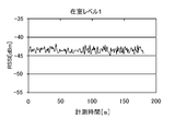
- FIG. 3B shows a graph of RSSI measured in the case of occupancy level 1.
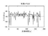
- FIG. 3C shows a graph of RSSI measured in the case of occupancy level 2.
- the graphs of FIGS. 3A to 3C are graphs of RSSI values measured by the receiver at predetermined time intervals.
- RSSI hardly fluctuates as shown in FIG. 3A.
- occupancy level 1 As shown in FIG. 3B, the range of fluctuation of RSSI is larger than in the case of absence.
- the RSSI fluctuation amount is the largest among the three conditions.
- RSSI variation was obtained for each of the three conditions.
- standard deviation was used as an index representing variation.
- the fixed period about 180 seconds was divided into periods of 30 seconds, and the standard deviation of RSSI (RSSI standard deviation) measured in each period was obtained.
- FIG. 4 shows a graph of the RSSI standard deviation.
- the variation in RSSI is the smallest in the absence, and the largest in the occupancy level 2.
- the variation in RSSI at the occupancy level 1 is larger than that at the absence, and smaller than that at the occupancy level 2.
- the ranges that can be taken by the standard deviation of RSSI of each of the three conditions are different and do not overlap each other. From this, absence, occupancy level 1, occupancy level 2 between each possible range (boundary) value as a threshold, by comparing the standard deviation of the RSSI of the detection signal and the threshold, Whether the occupancy level is 1 or the occupancy level 2 can be determined. For this reason, the value between the range that can be taken by the standard deviation of the absent RSSI and the range that can be taken by the standard deviation of the RSSI at the occupancy level 1 was set as the threshold value 1. The value between the range in which the standard deviation of RSSI at the occupancy level 1 can be taken and the range in which the standard deviation of RSSI at the occupancy level 2 can take was set as the threshold 2.
- the standard deviation of RSSI in the absence was within the range of 0.06 to 0.2 dB.
- the standard deviation of RSSI in the case of occupancy level 1 was in the range of 0.5 to 0.8 dB.
- the standard deviation of RSSI in the case of occupancy level 2 was in the range of 1.3 dB to 4.2 dB. Therefore, the threshold for distinguishing absence and occupancy level 1 (hereinafter referred to as threshold 1) was set to 0.3 dB, and the threshold for distinguishing between occupancy level 1 and occupancy level 2 (hereinafter referred to as threshold 2) was set to 1.0 dB.
- Threshold value 1 and threshold value 2 obtained prior to processing related to transmission interval control of the wireless sensor terminal 100 described later are stored in the threshold value table 223 of the control device 200. An example of data stored in the threshold table 223 is shown in FIG.
- Threshold value 1 and threshold value 2 are determined by the following method, for example. First, the detection signal is transmitted and received in the room 1 or in the same room as the room 1, and the RSSI is measured. Then, the standard deviation of RSSI is obtained from the measured value of RSSI, and threshold values 1 and 2 are obtained from the standard deviation of RSSI. Alternatively, the RSSI standard deviation, threshold value 1, and threshold value 2 are obtained by simulation using a computer. In the test and simulation for obtaining the threshold values 1 and 2, it is necessary to set the conditions of the space, the transmitter, the receiver, and the like to the same conditions as the conditions for actually measuring the detection signal.
- the control device 200 measures the RSSI of the received detection signal and obtains the RSSI standard deviation. Then, the control device 200 compares the RSSI standard deviation with the threshold value 1 and the threshold value 2 of the threshold value table 223 to determine the state of the room 1. When the state of the room 1 determined based on the threshold value 1 and the threshold value 2 is different from the previous determination result, the control device 200 transmits a control signal instructing the wireless sensor terminal 100 to change the detection signal transmission interval.
- the content of the instruction transmitted from the control device 200 to the wireless sensor terminal 100 is defined in the instruction table 225.
- FIG. 6 shows an example of data stored in the instruction table 225.
- the transmission interval at occupancy level 2 is the default. If the amount of fluctuation in the propagation path is expected to be small, such as changing from occupancy level 1 or occupancy level 2 to absence, or changing from occupancy level 2 to occupancy level 1, send Instructing to increase the interval is defined. In addition, when the amount of fluctuation in the propagation path is expected to increase, such as a change from absence to occupancy level 1 or occupancy level 2 or change from occupancy level 1 to occupancy level 2. Instructing to shorten the transmission interval is defined.
- threshold values 1 and 2 are obtained in advance and stored in the threshold value table 223 of the storage unit 220 of the control device 200.
- a default value (1 second) is set in the transmission interval parameter 123 of the storage unit 120 of the wireless sensor terminal 100.
- the default value is the transmission interval of the detection signal when the state of the room 1 is the occupancy level 2.
- the control unit 140 executes the transmission program 122 and performs the following processing.
- the control unit 140 causes the communication unit 110 to output a detection signal every time (one second) specified in the transmission interval parameter 123. Therefore, the radio wave (detection signal) output from the antenna 111 of the wireless sensor terminal 100 is repeatedly reflected, diffracted, and transmitted by the ceiling or floor of the room 1 and reaches the control device 200.
- control device 200 At the same time as the wireless sensor terminal 100 is turned on, the control device 200 is also turned on.
- the control unit 240 executes the determination program 222 and executes a series of processes shown in FIG.
- the control unit 240 stores the current time in the storage unit 220 as the start time (step S1001).
- the control unit 240 acquires the RSSI of the detection signal (step S1002). Specifically, the detection signal received by the antenna 211 is input to the control unit 240 via the wireless communication circuit 212.
- the control unit 240 measures the RSSI of the detection signal using a signal strength measurement circuit or the like, and stores the RSSI measurement value in the storage unit 220.
- the control unit 240 puts a wait for one cycle (one second) (step S1003). That is, it waits for 1 second.
- the control unit 240 determines whether or not a certain time (30 seconds) has elapsed from the start time (step S1004). When a certain time (30 seconds) has elapsed from the start time (step S1004; Yes), the control unit 240 calculates the RSSI standard deviation X from the RSSI acquired in the past 30 seconds (step S1005).
- the RSSI standard deviation X is stored in the storage unit 220 together with the current time.
- the control unit 240 compares the RSSI standard deviation X with the threshold 1 (step S1006). When the control unit 240 determines that the RSSI standard deviation X is equal to or less than the threshold 1 (step S1006; Yes), the control unit 240 determines that the state of the room 1 is absent, and stores the determination value “absence” in the determination history 224 together with the time. (Step S1007). On the other hand, if the control part 240 discriminate
- the control unit 240 determines that the state of the room 1 is the occupancy level 1, and sets the determination value “occupancy level 1” as the time. At the same time, it is stored in the discrimination history 224 (step S1009).
- the control unit 240 determines that the state of the room 1 is the occupancy level 2, and sets the determination value “occupancy level 2”.
- the determination history 224 is stored together with the time (step S1010).
- control unit 240 determines whether or not the previous determination value is the same as the current determination value (step S1011). Specifically, the control unit 240 reads, from the determination history 224 of the storage unit 220, the determination value stored with the time closest to the current time and the determination value stored with the time closest to the current time. Compare discriminant values. When the previous discriminant value and the current discriminant value are the same (step S1011; Yes), the control unit 240 deletes the RSSI measurement value stored in the storage unit 220 for 30 seconds, and then performs the process of step S1001 again. Return.
- the control unit 240 instructs the wireless sensor terminal 100 to change the time interval of transmission of the detection signal (step S1012). Specifically, the control unit 240 acquires an instruction to be transmitted to the wireless sensor terminal 100 from the instruction table 225 illustrated in FIG. 6 based on the previous determination value and the current determination value. The control unit 240 transmits a control signal indicating an instruction to the wireless sensor terminal 100 via the communication unit 210. For example, when the previous discriminant value is “in-room level 2” and the current discriminant value is “in-room level 1”, the control unit 240 indicates an instruction “change the transmission interval to 3 seconds”. A control signal is transmitted to the wireless sensor terminal 100. Thereafter, the control unit 240 deletes the RSSI measurement value stored in the storage unit 220 for 30 seconds, and then returns to the process of step S1001 again.
- the wireless sensor terminal 100 changes the value of the transmission interval parameter 123 of the storage unit 120 from the current default value to 3 seconds when receiving the control signal instructing the change of the transmission interval from the control device 200.
- the above is the transmission interval control processing according to the first embodiment.
- a multipath propagation environment that varies depending on the amount of human activity is considered.
- the wireless sensor terminal 100 outputs a detection signal at a transmission frequency according to a multipath propagation environment assumed by the state of the room 1. For this reason, the wireless sensor terminal 100 does not transmit a detection signal unnecessarily. Therefore, the power consumption of the wireless sensor terminal 100 can be reduced.
- the presence detection system 1000 can be easily and further reduced in cost. Can be built.
- the control device 200 discriminates (senses) the state of the room 1 and controls the transmission frequency of the detection signal based on the discrimination result. However, not only the control of the transmission frequency of the detection signal, but also the control device 200 can perform other controls using the determination result for the room 1.
- Each sensor of the sensor unit 130 of the wireless sensor terminal 100 performs measurement at a time interval defined in the transmission interval parameter 123.
- the control unit 140 transmits a value (environmental data) indicating the environment of the room 1 and a value (indoor data) relating to the occupants in the room 1 obtained by the measurement of the sensor unit 130 to the control device 200.
- the environmental data includes room temperature, room humidity, illuminance, carbon dioxide concentration, and the like.
- Indoor data includes measured values such as human feeling and distance.
- the control unit 140 transmits environmental data and room data to the control device 200 at intervals defined by the transmission interval parameter 123.
- the air conditioner 300 is performing a cooling operation.
- the air conditioner 300 includes a plurality of operation modes, and performs an operation according to the set operation mode.
- operation modes there are a normal mode, an energy saving mode, and a refresh mode.
- the air conditioner 300 operates to reduce the amount of power consumption compared to the normal mode.
- the refresh mode the air conditioner 300 ventilates the room 1 at a determined frequency during operation.
- the control device 200 controls the air conditioner 300 to operate in the normal mode in the occupancy level 2, the refresh mode in the occupancy level 1, and the energy saving mode in the absence.
- the transmission interval parameter 123 is set to “1 second” as a default value.
- “3 seconds” is set in the transmission interval parameter 123.
- “60 seconds” is set in the transmission interval parameter 123.
- control device 200 controls the air conditioner 300.
- the control device 200 is the same as in the first embodiment in the manner in which the presence / absence of a person in the room 1 and the activity state of the person are determined.
- the processing of the control device 200 when a person is present in the room 1 and the person is actively active, that is, at the occupancy level 2, will be described. Since the occupancy level is 2, the wireless sensor terminal 100 outputs detection signals at 1-second intervals. The control device 200 determines the presence / absence of the room 1 and the activity state of the person each time a detection signal is received.
- the wireless sensor terminal 100 transmits environmental data and room data to the control device 200 every second by the sensor unit 130 in parallel with the transmission of the detection signal. At this time, the air conditioner 300 is operating in the normal mode.
- Control device 200 determines that the state of occupancy 1 has changed from occupancy level 2 to absence.
- the control device 200 instructs the air conditioner 300 to operate in the energy saving mode.
- the air conditioner 300 switches the operation mode to the energy saving mode in response to an instruction from the control device 200.
- the control device 200 instructs the wireless sensor terminal 100 to set the transmission interval to 60 seconds (1 minute) in parallel with the instruction to the air conditioner 300. In response to this instruction, the wireless sensor terminal 100 sets “60 seconds” in the transmission interval parameter 123. Thereafter, the wireless sensor terminal 100 outputs detection signals at 60-second intervals. In addition, the wireless sensor terminal 100 transmits environmental data and room data to the control device 200 at intervals of 60 seconds.
- the control device 200 determines that the state of the occupancy 1 has changed from the absence to the occupancy level 2.
- the control device 200 instructs the air conditioner 300 to operate in the normal mode.
- the air conditioner 300 switches the operation mode to the normal mode.
- the control device 200 instructs the wireless sensor terminal 100 to set the transmission interval to 1 second (default value).
- the wireless sensor terminal 100 changes the transmission interval parameter 123 to “1 second”. Thereafter, the wireless sensor terminal 100 outputs detection signals at 1 second intervals.
- the wireless sensor terminal 100 transmits environmental data and room data to the control device 200 at 1 second intervals.
- the deviation of the RSSI standard deviation in communication between the control device 200 and the wireless sensor terminal 100 is less than the threshold 2 because the person is still sitting on the chair.
- the control device 200 determines that the occupancy level 2 has changed to the occupancy level 1.
- the control device 200 instructs the air conditioner 300 to operate in the refresh mode. In response to this instruction, the air conditioner 300 switches the operation mode to the refresh mode.
- the control device 200 instructs the wireless sensor terminal 100 to set the transmission interval to 3 seconds in parallel with the instruction to the air conditioner 300.
- the control device 200 instructs the air conditioner 300 to operate in the normal mode. .
- the control device 200 compares the RSSI variation with the determined criteria (threshold 1 and threshold 2) to determine the state of the room 1.
- the control device 200 controls the air conditioner 300 so as to perform an appropriate operation according to the state of the room 1 (the presence / absence of a person, the person's activity state).
- the control device 200 causes the air conditioner 300 to ventilate when a person in the room 1 is working while sitting for a long time.
- the control device 200 causes the air conditioner 300 to operate in the energy saving mode when the room 1 is absent.
- the control apparatus 200 can perform fine control according to the state of the room 1 regarding the control of the air conditioner 300.
- a dedicated device for presence detection is not required, and the presence detection system 1000 can be constructed easily and at a lower cost.
- the control device 200 may control the air conditioner 300 so that the normal mode and the refresh mode are switched at predetermined times in the occupancy level 1.
- the air conditioner 300 may transmit a signal to that effect to the control device 200.
- cooling operation has been described as an example, other operations that can be performed by the air conditioner 300 such as a heating operation and a dehumidifying operation can be similarly controlled.
- control unit 240 of the control device 200 may serve as an update unit that updates the threshold value 1 and the threshold value 2.
- the control unit 240 stores the RSSI measurement value of the received detection signal in the storage unit 220.
- the control unit 240 obtains an average value of measured values for a certain period determined to be absent from the storage unit 220.
- the control part 240 calculates
- control unit 240 similarly performs the same processing for the RSSI measurement values for a certain period determined as the occupancy level 1 and the occupancy level 2.
- the control unit 240 obtains new threshold values 1 and 2 from the possible range of the standard deviation of the RSSI of the detection signal in each state of absence, occupancy level 1 and occupancy level 2, and the threshold values in the threshold table 223 1.
- Update threshold 2 In this case, for example, in order to obtain the threshold 1, the measured value of RSSI when actually determined to be absent, and the measured value of RSSI when determined to be occupancy level 1 are used. Therefore, it is possible to determine the thresholds 1 and 2 that can be determined with higher accuracy.
- the control device can improve the detection accuracy of the presence / absence of a person and the active state by appropriately modifying the thresholds 1 and 2.
- the number of people working in the room 1 may differ every day of the week.
- the detection accuracy can be improved by storing the threshold values 1 and 2 for each day of the week in the storage unit 220 in advance.
- the state of the room 1 is determined using the variation (standard deviation) in received signal strength.
- the control part 240 accumulate
- the storage unit 220 stores ranges (for example, an upper limit value and a lower limit value) that can be obtained by the RSSI values in absence, occupancy level 1, and occupancy level 2 that have been obtained in advance by a test or the like.
- the control unit 240 compares the obtained average value with the upper limit value and the lower limit value of absence, occupancy level 1 and occupancy level 2, and the state of room 1 is absent, occupancy level 1, occupancy level 2 is discriminated.
- the transmission interval of the wireless sensor terminal 100 which is a transmitter of detection signals is controlled, but the reception interval of the control device 200 which is a receiver may be further controlled.
- a parameter defining a time interval for receiving a detection signal is stored in advance in the storage unit 220 of the control device 200.
- the control unit 240 receives the detection signal via the communication unit 210 every time specified by the parameter.
- the control unit 240 lengthens or shortens the time interval for receiving the detection signal according to the indoor state (absence, occupancy level 1, occupancy level 2). In this way, the power consumption of the control device 200 can be reduced.
- the room 1 is absent for a long time after a person leaves the room 1.
- Data indicating the life pattern of the person in the room 1 may be stored in the storage unit 220 in advance.
- the control unit 240 determines that the room 1 is absent for a long period of time based on the life pattern data when the occupancy level 1 or the occupancy level 2 changes to the absence, the control unit 240 operates the air conditioner 300. You may control to stop. Further, the control unit 240 may specify the date / time when the person enters the room 1 again based on the data of the life pattern, and pre-cool and pre-warm the room 1 in advance. In this way, it is possible to more effectively reduce power consumption when there is no person.
- control when it is determined that the occupancy level has changed from vacancy to occupancy level 2 or occupancy level 1, other control may be performed instead of simply switching to operation in the normal mode. For example, in the summer season, it is possible to perform control such as increasing the wind from the air conditioner 300 or decreasing the set temperature of the air conditioner 300 to increase the cooling capacity. In this way, comfort can be improved.
- the wireless sensor terminal 100 measures and transmits environmental data and the like with the same frequency as the detection signal. For this reason, it is possible to more accurately measure environmental data and the like by frequently measuring temperature, humidity, human feeling, distance, and carbon dioxide concentration, which have large fluctuation amounts when a person is present in the room. it can.
- the wireless sensor terminal 100 may store parameter information defining the measurement frequency of the sensor unit 130 and the transmission frequency of measurement values in the storage unit 120.
- the control device 200 may issue an instruction to change the parameter of the measurement frequency and the transmission frequency of the measurement value to the wireless sensor terminal 100 together with the instruction to update the transmission interval parameter 123.
- the control device 200 may instruct the wireless sensor terminal 100 for changing only one of the measurement frequency and the measurement value transmission frequency.
- the control device 200 may control other equipment devices, audio devices and the like without being limited to the air conditioner 300.
- the control device 200 can control lighting equipment, a water heater, a ventilation fan, an IH cooking heater, and the like.
- the control device 200 may instruct the lighting device to turn on when it is determined that a person has entered the room 1, and may instruct the lighting device to turn off when a person leaves the room 1.
- the control device 200 determines the state of the room 1 at a short time interval (for example, 100 ms).
- the equipment to be managed by the control device 200 is a device that does not require an emergency stop for safety, such as an air conditioner, the control device 200 needs to shorten the time interval for determining the state of the room 1. There is no.
- the control device 200 stores the RSSI of the detection signal received in a certain period in the storage unit 220.
- the control apparatus 200 calculates
- the control device obtains a maximum value and a minimum value of RSSI when it is determined that the occupancy level is 1 and the occupancy level 2 for the RSSI of the detection signal received during a certain period.
- the control device 200 stores the maximum value and the minimum value of absence, occupancy level 1 and occupancy level 2 in advance.
- the control device 200 determines the state of the room 1 depending on whether the RSSI of the received detection signal is included in the absence, occupancy level 1 or occupancy level 2 range (between the maximum value and the minimum value). Determine.
- the communication interval of the detection signal may be arbitrarily determined for each category.
- the control device 200 may perform control to increase the communication frequency only when it is determined that a person is in the room 1 and the amount of activity is large.
- control device 200 may first determine the state of the room 1 depending on which range the majority of the received signal strengths of the detection signals received in a certain period correspond to the threshold values 1 and 2. Good. In addition, when the control device 200 determines that the occupancy level is 1 and the occupancy level 2, the majority of the received signal strengths of the detection signals received in a certain period belong to different ranges. It may be determined that there is a change in the activity level of the person existing in the room. Or it is good also as 70% and 80% instead of a majority.
- the state of the room 1 corresponds to any of the three categories of absence, occupancy level 1 and occupancy level 2.
- the number of sections is not limited to three.
- four categories of occupancy level 1, occupancy level 2, and occupancy level 3 when there is a person in room 1 may be used.
- threshold value 1 to threshold value 3 are used in order to determine which of the four categories is applicable.
- the threshold value may be increased according to the number of sections. The threshold value can be determined by a test performed in advance.
- the example of the room 1 has been described as the space to be detected.
- the space to be detected is basically indoors but may be outdoor.
- the space to be detected may extend over a plurality of rooms in the building.
- air conditioner 300 and one control device 200 are connected.
- a plurality of air conditioners 300 may be connected to the control device 200.
- the air conditioner 300 and the control device 200 may be connected via a network. Examples of the network include a management network using a dedicated line for equipment and a LAN.
- the control device 200 can be used for communication from outside the room as long as it is a radio wave that emits a radio wave with a certain output and a certain period.
- a radio wave for TV communication or a radio wave from a mobile phone base station can be used as the detection signal.
- the air conditioner 300 may have a remote controller provided in the same room.
- a remote controller may be used as the wireless sensor terminal 100.
- the control device 200 determines the state of the room 1 based on the detection signal output from the remote controller.
- an information terminal device such as a PC in which a program that defines the above-described transmission interval control processing or the like is installed may be employed.
- the distribution method of the program is arbitrary. For example, it is stored in a computer-readable recording medium such as a CD-ROM (Compact Disk Read-Only Memory), a DVD (Digital Versatile Disk), an MO (Magneto Optical Disk), or a memory card. It may be distributed via a communication network such as the Internet.
Landscapes
- Business, Economics & Management (AREA)
- Emergency Management (AREA)
- Physics & Mathematics (AREA)
- General Physics & Mathematics (AREA)
- Health & Medical Sciences (AREA)
- General Health & Medical Sciences (AREA)
- Gerontology & Geriatric Medicine (AREA)
- Air Conditioning Control Device (AREA)
- Geophysics And Detection Of Objects (AREA)
- Emergency Alarm Devices (AREA)
Abstract
制御装置(200)は、人の存在又は不存在を検知するための検知信号を送信する無線センサ端末(100)と通信する。制御装置(200)は、決められた期間内に受信した検知信号の信号強度のばらつきを取得し、ばらつきに基づいて、室内(1)に人が存在しない第1の状況、室内(1)に人が存在しており且つ人の活動状態が第1の状態である第2の状況、室内(1)に人が存在しており且つ人の活動状態が第2の状態である第3の状況、の少なくとも3つの状況のうち空間の状況がいずれであるかを判別する。制御装置(200)は、判別した結果と、前回判別した結果と、が異なる場合に、無線センサ端末(100)に対して検知信号の送信の時間間隔を変えるよう指示する。
Description
本発明は、無線通信装置、存在検知システム、方法、及びプログラムに関する。
決められた空間内の人の動きによって、空間内のマルチパス環境での電波(検知信号)の受信信号強度が変動する原理を利用し、人が存在するか否かを検出する存在検知システムが提案されている。
特許文献1には、検知信号としてTV放送電波を使用し、マルチパス環境での電波の受信レベルの変動に基づいて屋内空間に人が存在するか否かを検出するシステムが開示されている。特許文献2には、住居内の生活者の異常の有無を検知するため、無線アクセスポイントが出力した電波の強度の変化量が閾値を上回るか否かを判別することが開示されている。特許文献3には、空気調和機を適切に制御するため、無線信号の受信信号強度の標準偏差に基づいて、室内にいる人の数を検出するシステムが開示されている。
室内に人が存在するか否かを検出する精度を上げるためには、検知信号の送信回数を多くする、つまり、無線信号を出力する時間間隔を短くすればよい。しかし、この場合、送信機、受信機の消費電力量が大きくなってしまう。
送信機、受信機の消費電力量を低減するため、次のような手法がある。特許文献4には、人が不在であるとき無線信号の受信レベルを基準値とし、無線信号の受信レベルが基準値から変化した場合に、無線信号の送受信間隔を短くすることが記載されている。また、特許文献5には、受信状態と非受信状態とを間欠的に繰り返す間欠受信方式において、複数回スタート信号を受信したことをトリガとして、受信状態に遷移することが記載されている。
従来の存在検知システムでは、検知対象となる空間内に人が存在するか否かだけを検知している。このため、空間内に人が存在する場合は、人の活動状態にかかわらず、存在検知のための機器(送信機、受信機等)について消費電力の低減等に関する単一の制御を行う。例えば、人が椅子にじっと座っているといった、空間内にいる人の動きがほとんどない場合、検知信号の伝播経路の変動はほとんどない。よって、検知信号の受信レベルは安定する。例えば、人が空間内を歩き回っているといった、空間内にいる人が動いている場合、人により検知信号の伝搬経路が遮断され、検知信号が人により反射する。よって、検知信号の受信レベルは安定しない。言い換えると、空間内にいる人の活動状態に応じて、マルチパス伝播環境が変化する。このため、空間内に人が存在する場合に単一の制御を行った場合には、消費電力の低減等に関する適切な制御を行うことができない。
本発明は、上記のような問題点を解決するためになされたもので、検知対象の空間内に人が存在するか否か、人が存在する場合には人の活動状態を判別し、判別した結果に基づいて検知信号の通信頻度を増減させることにより、存在検知のための機器の消費電力を低減することを目的とする。
本発明に係る無線通信装置は、人の存在又は不存在を検知するための検知信号を送信する送信機と通信する無線通信装置である。取得手段は、決められた期間内に受信した検知信号の信号強度のばらつきを取得する。判別手段は、ばらつきに基づいて、空間内に人が存在しない第1の状況、空間内に人が存在しており且つ人の活動状態が第1の状態である第2の状況、空間内に人が存在しており且つ人の活動状態が第2の状態である第3の状況、の少なくとも3つの状況のうち空間の状況がいずれであるかを判別する。指示手段は、判別手段が判別した結果と、判別手段が前回判別した結果と、が異なる場合に、送信機に対して検知信号の送信の時間間隔を変えるよう指示する。
本発明によれば、検知対象の空間内に人が存在する場合に、人の活動状態に応じて検知信号の送信の時間間隔を制御し、検知信号の通信に係る機器の消費電力を低減することができる。
(実施の形態1)
以下、本発明の実施の形態に係る存在検知システム1000を図面を参照しながら説明する。存在検知システム1000は、検知対象の空間内にある機器が有する無線通信機能を利用して、検知対象の空間内に人が存在するか否か、人が存在する場合には人の活動状態を判別する。さらに、存在検知システム1000は、人の存在/不存在、人の活動状態に応じて、検知信号の通信の頻度を制御する。
以下、本発明の実施の形態に係る存在検知システム1000を図面を参照しながら説明する。存在検知システム1000は、検知対象の空間内にある機器が有する無線通信機能を利用して、検知対象の空間内に人が存在するか否か、人が存在する場合には人の活動状態を判別する。さらに、存在検知システム1000は、人の存在/不存在、人の活動状態に応じて、検知信号の通信の頻度を制御する。
図1を参照する。以下の説明において、存在検知システム1000が検知対象とする空間が室内1である例を説明する。存在検知システム1000は、検知信号を出力(送出)する無線センサ端末100と、検知信号を受信し、人の存在/不存在、人の活動状態を判別する制御装置200と、を含む。制御装置200は、設備機器を集中管理する集中コントローラである。ここでは、制御装置200は、専用線2で接続されている空気調和機300を集中管理する。空気調和機300は、協働して空調機能を提供する室内機301及び室外機302を備える。
無線センサ端末100と、制御装置200と、空気調和機300の室内機301と、は室内1に設置されている。空気調和機300の室外機302は屋外、つまり室内1の外に設置されている。
無線センサ端末100は、検知信号を出力(送出)する送信機としての役割を果たす。このため、無線センサ端末100は、決められた出力レベル以上の無線信号を出力することが要求される。無線センサ端末100は、室内1の壁等に固定されている必要はないが、少なくとも決められた期間その位置が変わらないことが必要である。無線センサ端末100は、例えば、室内1に存在するPC(Personal Computer)、無線LANアクセスポイント、無線LANアクセスポイント機能を備えた無線LANルータ、室内1に備えられる空気調和機300のリモートコントローラである。実施の形態1においては、無線センサ端末100がノート型PCである例を説明する。
無線センサ端末100の構成を説明する。なお、検知信号の通信に係る構成を中心に説明する。無線センサ端末100は、他の装置と通信する通信部110、無線センサ端末100の動作に必要なプログラム、データを記憶する記憶部120、各種センサを含むセンサ部130、無線センサ端末100全体を制御する制御部140を含む。無線センサ端末100の各部はバス160で接続されている。
通信部110は、制御部140の制御に従って、他の装置と無線通信を行う。通信部110は、アンテナ111、無線通信回路112を有する。無線通信回路112は、変復調回路と帯域制限フィルタとアンプとを含む。制御部140から検知信号を示す情報信号が供給されると、無線通信回路112は、変調処理、帯域制限処理、信号増幅処理等を行い、無線信号をアンテナ111に出力する。従って、アンテナ111から決められた周波数の電波が出力される。また、アンテナ111が電波を受信すると、無線通信回路112は、帯域制限処理、復調処理等により無線信号を復調し、復調信号(情報信号)を制御部140に出力する。
通信部110は、無線通信により検知信号を制御装置200に送信する。通信部110が出力する検知信号は、例えば、WiFi(登録商標)、920MHz、400MHzの特小通信等の規格に則ったものである。検知信号は、ビーコン信号であってもよいし、あるいは、決められた通信信号であってもよい。
アンテナ111から出力された電波は、室内1の天井や床、又は配置されている什器等により、反射、回折、透過を繰り返し、制御装置200に到達する。従って、制御装置200は、検知信号としてマルチパスな無線信号を受信する。
なお、人が無線センサ端末100を持ち運んでいる場合は、無線センサ端末100を送信機として使用することはできない。制御部140は、例えば、無線センサ端末100に内蔵されている加速度センサ、角速度センサにより、無線センサ端末100が静止していないことを検出した場合、通信部110に検知信号を出力させない。
また、通信部110は、センサ部130により取得された室内温度、室内湿度等を含む室内1の環境に関する測定値を無線通信により制御装置200に送信する。
記憶部120は、RAM(Random Access Memory)、ROM(Read Only Memory)、フラッシュメモリ等を含む。記憶部120は、無線センサ端末100全体を制御するOS121、検知信号の送信に係る送信プログラム122、検知信号の送信間隔を示す送信間隔パラメータ123を記憶する。
センサ部130は、温度センサ、湿度センサ、照度センサ、二酸化炭素濃度センサ、距離センサ、人感センサ、を含む。二酸化炭素濃度センサは室内1の二酸化炭素濃度を測定する。距離センサは無線センサ端末100から室内1にいる人等までの距離を測定する。人感センサは、室内1の人の所在を検出する。センサ部130の各センサは決められた時間間隔で測定を行う。
制御部140は、CPU(Central Processing Unit)等のプロセッサ、ワークメモリ、計時装置を含む。制御部140は、記憶部120に格納されたOS121を実行して、無線センサ端末100全体を制御する。また、制御部140は、記憶部120に格納された送信プログラム122を実行して、送信間隔パラメータ123で規定された時間毎で、通信部210に検知信号を出力させる。制御部140は、さらに、制御装置200から検知信号の送信の送信頻度を変更するよう指示されると、送信間隔パラメータ123の値を更新する。
制御装置200は、検知信号を受信する受信機である。制御装置200は、検知信号を受信し、検知信号に基づいて室内1に人が存在するか否か、存在する場合には人の活動状態を判別する。さらに、制御装置200は、無線センサ端末100に対して、検知信号の送信頻度を変更することを指示する。さらに、制御装置200は、空気調和機300を集中管理する。
制御装置200の構成を説明する。なお、検知信号の通信、無線センサ端末100の制御に係る構成を中心に説明する。制御装置200は、他の装置と通信する通信部210、制御装置200の動作に必要なプログラム、データを記憶する記憶部220、入出力インタフェースを含む入出力部230、制御装置200の動作に必要なプログラム、制御装置200全体を制御する制御部240を含む。制御装置200の各部はバス260で接続されている。
通信部210は、制御部240の制御に従って、他の装置と無線通信を行う。通信部210は、アンテナ211、無線通信回路212、有線通信回路213を有する。無線通信回路212は、変復調回路と帯域制限フィルタとアンプとを含む。アンテナ211が電波を受信すると、無線通信回路212は、帯域制限処理、復調処理、信号増幅処理等を行い、復調信号(情報信号)を制御部240に出力する。また、制御部240から検知信号を示す情報信号が供給されると、無線通信回路212は、変調処理、帯域制限処理、信号増幅処理等を行い、無線信号をアンテナ211に出力する。
有線通信回路213は、専用線2を介して、空気調和機300と相互に有線通信を行う。制御装置200と空気調和機300とは、空気調和機300の運転に関する制御信号を相互にやりとりする。
記憶部220は、RAM、ROM、フラッシュメモリ等を含む。記憶部220は、制御装置200全体を制御するOS221、検知信号に基づいて室内1の人の存在/不存在、人の活動状態を判別するための判別プログラム222を記憶する。さらに、記憶部220は、人の存在/不存在、人の活動状態の判別処理のための閾値を格納する閾値テーブル223、人の存在/不存在、人の活動状態を判別した結果を蓄積する判別履歴224、検知信号の送信の時間間隔(以下、送信間隔)に関する指示が定義された指示テーブル225を含む。閾値テーブル223、指示テーブル225の詳細は後述する。
入出力部230は、ユーザインタフェースであり、ボタン、タッチパネル等の入力装置と、ディスプレイ、スピーカ等の出力装置と、を含む。例えば、入出力部230は、ボタン操作を検出すると、ボタン操作に対応した操作信号を制御部240に出力する。また、入出力230は、制御部240から供給された画像信号に基づいた画像をディスプレイに表示する。
制御部240は、CPU等のプロセッサ、ワークメモリ、計時装置を含む。さらに、制御部240は、検知信号の受信信号強度を測定するための手段(受信信号強度測定回路等)を含む。制御部240は、記憶部220に格納されたOS221を実行して、制御装置200全体を制御する。また、制御部240は、判別プログラム222を実行して、図2に示す取得部241、判別部242、指示部243として機能する。
取得部241は、一定期間(例えば、30秒間)に通信部210が受信した検知信号の受信信号強度(RSSI)を測定する。さらに、取得部241は、一定期間に測定したRSSIの測定値から、RSSIの標準偏差を求める。
判別部242は、取得部241が求めたRSSIの標準偏差に基づいて、室内1に人が存在するか否か、人が存在する場合には人の活動状態を判別する。さらに、判別部242は、前回の判別結果と今回の判別結果とを比較し、室内1の状態が変化したか否かを判別する。
指示部243は、判別部242が室内1の状態が変化したと判別すると、無線センサ端末100に検知信号の送信間隔の変更を指示する。
次に、検知対象の空間の状態(人の存在/不存在、人の活動状態)を判別する基準の決定方法を説明する。
室内1に人がいない場合、検知信号の電波の伝搬経路の変動はない。このため、制御装置200における電波の受信レベル(受信信号強度)はほぼ一定となる、つまり、安定している。室内1に人がいる場合、伝搬経路が遮断されたり、電波が人により反射する。このため、検知信号の受信信号強度は、小さくなったり大きくなったり、つまり、変動する。室内1にいる人の動作も、検知信号の受信信号強度の変動に影響を与える。例えば、検知対象の空間で人が歩行していると、受信信号強度は、数秒間で10dB~15dBの範囲で変動する。一方で、検知対象の空間にいる人がほぼ静止している場合は、人が歩行している場合に比べ、受信信号強度の変動量は大きくない。これは、人のいる位置、人の腕や足の位置がほぼ変わらないためである。言い換えると、マルチパス伝播環境は、検知対象の空間に存在する人の活動量によって変化する。
このことを踏まえ、検知対象の空間の状態(人の存在/不存在、人の活動状態)と検知信号の受信信号強度の関係を調べた。まず、(1)検知対象の空間に人が存在しない場合(以下、不在という)、(2)検知対象の空間に人が存在し、人の活動量が小さい場合(以下、在室レベル1という)、(3)検知対象の空間に人が存在し、人の活動量が大きい場合(以下、在室レベル2という)、の3つの条件において、検知信号のRSSIを一定期間(約180秒間)測定した。在室レベル1では、1人の人が椅子にじっと座り、デスクワーク(タイピング、書き物等)を行っている、在室レベル2では、1人の人が受信機の周囲1mの範囲内であって、送信機と受信機との間を横切りながら、秒速2歩程度で歩き続けている。ここでは、検知対象の空間として、室内1と同じ条件の室内において、無線センサ端末100と同様の構成を備える送信機と、制御装置200と同様の構成を備える受信機とを使用して、RSSIを測定した。送信機は、決められた頻度で検知信号を連続して送信した。
図3Aに、不在の場合に測定されたRSSIのグラフを示す。図3Bに、在室レベル1の場合に測定されたRSSIのグラフを示す。図3Cに、在室レベル2の場合に測定されたRSSIのグラフを示す。図3A~図3Cのグラフは、受信機が決められた時間間隔で測定したRSSIの値をグラフ化したものである。
不在の場合、図3Aに示すように、RSSIはほとんど変動することがない。在室レベル1の場合、図3Bに示すように、不在の場合に比べるとRSSIの変動の幅が大きくなる。在室レベル2の場合は、図3Cに示すように、3つの条件のうちで最もRSSIの変動量が大きい。
また、3つの条件それぞれについて、RSSIのばらつきを求めた。ここでは、ばらつきを表す指標として標準偏差を使用した。具体的には、一定期間(約180秒間)を30秒間毎の期間に区切り、それぞれの期間に測定したRSSIの標準偏差(RSSI標準偏差)を求めた。図4にRSSI標準偏差のグラフを示す。RSSIのばらつきは、不在の場合が最も小さく、在室レベル2の場合が最も大きい。在室レベル1のRSSIのばらつきは、不在の場合より大きく、在室レベル2の場合より小さい。
図4に示すように、3つの条件のそれぞれのRSSIの標準偏差が取り得る範囲は、異なっており、相互に重なっていない。このことより、不在、在室レベル1、在室レベル2がそれぞれ取り得る範囲の間(境界)の値を閾値として求め、検知信号のRSSIの標準偏差と閾値とを比較することで、不在、在室レベル1、在室レベル2のいずれであるかを判別できる。このため、不在のRSSIの標準偏差が取り得る範囲と、在室レベル1のときのRSSIの標準偏差が取り得る範囲と、の間の値を閾値1とした。在室レベル1のときのRSSIの標準偏差が取り得る範囲と、在室レベル2のときのRSSIの標準偏差が取り得る範囲と、の間の値を閾値2とした。
ここでは、不在の場合のRSSIの標準偏差は0.06~0.2dBの範囲内にあった。在室レベル1の場合のRSSIの標準偏差は0.5~0.8dBの範囲内にあった。在室レベル2の場合のRSSIの標準偏差は1.3dB~4.2dBの範囲内にあった。よって、不在と在室レベル1を区分する閾値(以下、閾値1)を0.3dB、在室レベル1と在室レベル2を区分する閾値(以下、閾値2)を1.0dBとした。後述の無線センサ端末100の送信間隔の制御に係る処理に先立って求められた閾値1、閾値2は、制御装置200の閾値テーブル223に格納される。閾値テーブル223に格納されるデータの一例を図5に示す。
閾値1、閾値2は、例えば次のような方法で決定される。まず、室内1又は室内1と同じ条件の室内において、検知信号の送信及び受信を行い、RSSIを測定する。そして、RSSIの測定値からRSSIの標準偏差を求め、RSSIの標準偏差から閾値1、閾値2を求める。あるいは、コンピュータを使用したシミュレーションにより、RSSIの標準偏差、閾値1、閾値2を求める。なお、閾値1、閾値2を求めるための試験、シミュレーションは、空間、送信機、受信機等の条件を、実際に検知信号の測定を行う条件と同じ条件とする必要がある。
制御装置200は、まず、受信した検知信号のRSSIを測定し、RSSI標準偏差を求める。そして、制御装置200は、RSSI標準偏差と閾値テーブル223の閾値1、閾値2と、を比較して、室内1の状態を判別する。制御装置200は、閾値1、閾値2に基づいて判別した室内1の状態が、前回の判別結果と異なる場合、無線センサ端末100に検知信号の送信間隔の変更を指示する制御信号を送信する。
制御装置200が無線センサ端末100に送信する指示の内容は、指示テーブル225に定義されている。図6に、指示テーブル225に格納されるデータの一例を示す。ここでは、在室レベル2のときの送信間隔をデフォルトとする。在室レベル1又は在室レベル2から不在の状態に変化する、在室レベル2から在室レベル1に変化する、といった、伝播経路の変動量が小さくなることが予想される場合には、送信間隔を長くするよう指示することが定義されている。また、不在の状態から在室レベル1又は在室レベル2に変化する、在室レベル1から在室レベル2に変化する、といった、伝搬経路の変動量が大きくなることが予想される場合には、送信間隔を短くするよう指示することが定義されている。
次に、制御装置200が実行する送信間隔制御処理を説明する。なお、閾値1、閾値2は予め求められ、制御装置200の記憶部220の閾値テーブル223に記憶されている。無線センサ端末100の記憶部120の送信間隔パラメータ123にはデフォルト値(1秒)が設定されている。デフォルト値は、室内1の状態が在室レベル2である場合の検知信号の送信間隔である。
無線センサ端末100に電源が投入されると、制御部140は送信プログラム122を実行して以下の処理を行う。制御部140は、送信間隔パラメータ123に規定されている時間(1秒間)毎に、通信部110に検知信号を出力させる。従って、無線センサ端末100のアンテナ111から出力された電波(検知信号)は、室内1の天井や床等により、反射、回折、透過を繰り返し、制御装置200に到達する。
無線センサ端末100の電源投入と併行して、制御装置200にも電源が投入される。制御部240は、判別プログラム222を実行して、図7に示す一連の処理を実行する。
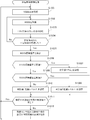
制御部240は、現在時刻を開始時刻として記憶部220に記憶する(ステップS1001)。制御部240は、検知信号のRSSIを取得する(ステップS1002)。具体的には、アンテナ211で受信された検知信号は、無線通信回路212を介して、制御部240に入力される。制御部240は、信号強度測定回路等を使用して検知信号のRSSIを測定し、RSSIの測定値を記憶部220に記憶する。
制御部240は、1サイクル(1秒間)のウェイトをはさむ(ステップS1003)。つまり、1秒間待機する。制御部240は、開始時刻から一定時間(30秒間)が経過したか否かを判別する(ステップS1004)。開始時刻から一定時間(30秒間)が経過した場合(ステップS1004;Yes)、制御部240は、過去30秒間に取得したRSSIからRSSI標準偏差Xを算出し(ステップS1005)。RSSI標準偏差Xを現在時刻とともに記憶部220に記憶する。
制御部240は、RSSI標準偏差Xと閾値1とを比較する(ステップS1006)。制御部240は、RSSI標準偏差Xが閾値1以下であると判別すると(ステップS1006;Yes)、室内1の状態が不在であると判別し、判別値「不在」を時刻とともに判別履歴224に記憶する(ステップS1007)。一方、制御部240は、RSSI標準偏差Xが閾値1より大きいと判別すると(ステップS1006;No)、ステップS1008に進む。制御部240は、RSSI標準偏差Xと閾値2とを比較する(ステップS1008)。制御部240は、RSSI標準偏差Xが閾値2以下であると判別すると(ステップS1008;Yes)、室内1の状態が在室レベル1であると判別し、判別値「在室レベル1」を時刻とともに判別履歴224に記憶する(ステップS1009)。一方、制御部240は、RSSI標準偏差Xが閾値2より大きいと判別すると(ステップS1008;No)、室内1の状態が在室レベル2であると判別し、判別値「在室レベル2」を時刻とともに判別履歴224に記憶する(ステップS1010)。
次に、制御部240は、前回の判別値と今回の判別値とが同じか否かを判別する(ステップS1011)。具体的には、制御部240は記憶部220の判別履歴224から、現在時刻に最も近い時刻とともに記憶された判別値と、現在時刻に次に近い時刻とともに記憶された判別値を読み出し、2つの判別値を比較する。前回の判別値と今回の判別値とが同じ場合(ステップS1011;Yes)、制御部240は、30秒間に記憶部220に記憶したRSSIの測定値を削除し、その後、再びステップS1001の処理に戻る。
一方、前回の判別値と今回の判別値とが異なる場合(ステップS1011;No)、制御部240は、無線センサ端末100に検知信号の送信の時間間隔の変更を指示する(ステップS1012)。具体的には、制御部240は、前回の判別値と今回の判別値に基づいて、図6に示す指示テーブル225から無線センサ端末100に送信する指示を取得する。制御部240は指示を示す制御信号を通信部210を介して無線センサ端末100に送信する。例えば、前回の判別値が「在室レベル2」であり、今回の判別値が「在室レベル1」である場合、制御部240は、「送信間隔を3秒に変更する」という指示を示す制御信号を、無線センサ端末100に送信する。その後、制御部240は、30秒間に記憶部220に記憶したRSSIの測定値を削除し、その後、再びステップS1001の処理に戻る。
無線センサ端末100は、制御装置200から送信間隔の変更を指示する制御信号を受信すると、記憶部120の送信間隔パラメータ123の値を現在のデフォルト値から3秒に変更する。
以上が実施の形態1に係る送信間隔制御処理である。実施の形態1では、人の活動量によって変動するマルチパス伝播環境が考慮される。ここでは、人が存在している場合の室内1の状態を、人の活動量が小さい状態(在室レベル1)、人の活動量が大きい状態(在室レベル2)に区分する例を説明した。このような構成により、無線センサ端末100は、室内1の状態により想定されるマルチパス伝播環境に応じて送信頻度で検知信号を出力する。このため、無線センサ端末100は検知信号を不必要に送信することがない。よって、無線センサ端末100の消費電力を低減できる。
さらに、本実施の形態では、アレイアンテナといった無線機器、その他の存在検知のための専用の機器を必要としない。無線センサ端末100としての無線通信機能を備えたPC等の端末と、空気調和機300の集中管理の装置である制御装置200と、を使用して、存在検知システム1000を簡易に、さらに低コストに構築できる。
実施の形態1では、制御装置200は、室内1の状態を判別(センシング)し、判別した結果に基づいて検知信号の送信頻度を制御した。しかし、検知信号の送信頻度の制御に限らず、制御装置200は、室内1についての判別結果を使用して他の制御を行うことができる。
(実施の形態2)
実施の形態2では、制御装置200が室内1の状態を判別し、判別結果に基づいて空気調和機300の運転を制御する例を説明する。存在検知システム1000に含まれる各機器の構成は、実施の形態1と同様である。
実施の形態2では、制御装置200が室内1の状態を判別し、判別結果に基づいて空気調和機300の運転を制御する例を説明する。存在検知システム1000に含まれる各機器の構成は、実施の形態1と同様である。
無線センサ端末100のセンサ部130の各センサは、送信間隔パラメータ123に規定されている時間間隔で測定を行う。制御部140は、センサ部130の測定により得られた、室内1の環境を示す値(環境データ)と室内1の在室者に関する値(室内データ)とを、制御装置200に送信する。環境データは、室内温度、室内湿度、照度、二酸化炭素濃度等を含む。室内データは、人感、距離等の測定値を含む。制御部140は、環境データ、室内データを、送信間隔パラメータ123に規定されている間隔で制御装置200に送信する。
以下の説明においては、空気調和機300が冷房運転を行っている場面を想定する。空気調和機300は、複数の運転モードを備えており、設定された運転モードに応じた運転を行う。運転モードとして、通常モード、省エネモード、リフレッシュモードがある。省エネモードでは、空気調和機300は、通常モードに比べ、消費電力量を低減するような運転を行う。リフレッシュモードでは、空気調和機300は、運転中、決められた頻度で室内1の換気を行う。
制御装置200は、在室レベル2では通常モードで、在室レベル1ではリフレッシュモードで、不在では省エネモードで、運転するよう空気調和機300を制御する。
在室レベル2の状態では、送信間隔パラメータ123にはデフォルト値である「1秒」が設定される。在室レベル1の状態では、送信間隔パラメータ123には、「3秒」が設定される。不在の状態では、送信間隔パラメータ123には、「60秒」が設定される。
図8を参照して、制御装置200が空気調和機300を制御する処理を説明する。なお、制御装置200が、室内1の人の存在/不存在、人の活動状態を判別する手法は実施の形態1と同様である。
まず、室内1に人が存在しており、人が活発に活動している、つまり、在室レベル2である場合の制御装置200の処理を説明する。在室レベル2であるため、無線センサ端末100は1秒間隔で検知信号を出力する。制御装置200は、検知信号を受信するたび、室内1の在室/不在、人の活動状態を判別する。
無線センサ端末100は、検知信号の送信と併行して、センサ部130により環境データ、室内データを1秒毎に制御装置200に送信する。また、このとき、空気調和機300は、通常モードで運転を行っている。
その後、室内1から人がいなくなった場合を想定する。人が、室内1の外へ、つまり、存在検知システム1000の圏外に移動するため、無線センサ端末100と制御装置200の通信におけるRSSI標準偏差の偏移が閾値1以下になる。制御装置200は、在室1の状態が在室レベル2から不在に変化したと判別する。制御装置200は、空気調和機300に省エネモードで運転するよう指示する。空気調和機300は、制御装置200からの指示に応答して、運転のモードを省エネモードに切り替える。
制御装置200は、空気調和機300への指示と併行して、送信間隔を60秒(1分)とするよう無線センサ端末100に指示する。無線センサ端末100は、この指示に応答して、送信間隔パラメータ123に「60秒」を設定する。その後、無線センサ端末100は検知信号を60秒間隔で出力する。また、無線センサ端末100は、環境データ、室内データを60秒間隔で制御装置200に送信する。
その後、室内1に人が入ってきたことを想定する。人が室内1に歩いて入ってくることにより、RSSI標準偏差の偏移が閾値2を超える。制御装置200は、在室1の状態が不在から在室レベル2に変化したと判別する。制御装置200は、空気調和機300に対して、通常モードで運転するよう指示する。空気調和機300は、この指示に応答して、運転のモードを通常モードに切り替える。制御装置200は、空気調和機300への指示と併行して、送信間隔を1秒(デフォルト値)とするよう無線センサ端末100に指示する。無線センサ端末100は、この指示に応答して、送信間隔パラメータ123に「1秒」に変更する。その後、無線センサ端末100は検知信号を1秒間隔で出力する。また、無線センサ端末100は、環境データ、室内データを1秒間隔で制御装置200に送信する。
その後、室内1にいる人が、椅子に座ってデスクワークを開始したことを想定する。人が椅子にじっと座ったままでいることで、制御装置200と無線センサ端末100の通信における、RSSI標準偏差の偏移が閾値2を下回る。制御装置200は、RSSI標準偏差が閾値2を下回り、且つ閾値1を超えていると判別すると、在室レベル2から在室レベル1に変化したと判別する。制御装置200は、空気調和機300に対して、リフレッシュモードで運転するよう指示する。空気調和機300は、この指示に応答して、運転のモードをリフレッシュモードに切り替える。制御装置200は、空気調和機300への指示と併行して、送信間隔を3秒とするよう無線センサ端末100に指示する。以上が図8に示す空気調和機300の制御に係るシーケンスである。
また、図8には図示していないが、制御装置200は、在室レベル1から在室レベル2に変化したと判別した場合、空気調和機300に対して、通常モードで運転するよう指示する。
以上に説明したように、制御装置200は、RSSIのばらつきと決められた基準(閾値1、閾値2)とを比較して室内1の状態を判別した。制御装置200は、室内1の状態が変化した場合に、室内1の状態(人の存在/不存在、人の活動状態)に応じた適切な運転を行うよう空気調和機300を制御する。例えば、制御装置200は、室内1にいる人が長時間座ったまま作業している場合等に、空気調和機300に換気を行わせる。制御装置200は、室内1が不在の場合に空気調和機300に省エネモードで運転させる。このように、制御装置200は、空気調和機300の制御に関し、室内1の状態に応じた細やかな制御を行うことができる。
さらに、実施の形態2においても、存在検知のための専用の機器を必要とせず、存在検知システム1000を簡易に、さらに低コストに構築できる。
上述の例では、在室レベル1では、空気調和機300がリフレッシュモードで運転する例を説明した。あるいは、制御装置200は、在室レベル1では、通常モードとリフレッシュモードを決められた時間毎に切り替えるよう、空気調和機300を制御してもよい。また、空気調和機300は、運転モードを切り替えた場合に、その旨を通知する信号を制御装置200に送信してもよい。
また、冷房運転を例に説明したが、暖房運転、除湿運転等の空気調和機300が可能な他の運転についても同様に制御することができる。
(変形例1)
また、制御装置200の制御部240は、閾値1、閾値2を更新する更新部としての機能を果たしてもよい。例えば、制御部240は、受信した検知信号のRSSIの測定値を記憶部220に記憶しておく。制御部240は、記憶部220から不在と判別した一定期間の測定値の平均値を求める。さらに、制御部240は、当該期間のRSSIの測定値と、求めた平均値から標準偏差を求める。制御部240は、これを複数回繰り返し、不在と判別したときのRSSIの測定値に基づく標準偏差を複数求める。さらに、制御部240は、同様に、在室レベル1、在室レベル2と判別した一定期間のRSSIの測定値についても同様の処理を行う。制御部240は、不在、在室レベル1、在室レベル2のそれぞれの状態において、検知信号のRSSIの標準偏差が取り得る範囲から、新たな閾値1、閾値2を求め、閾値テーブル223の閾値1、閾値2を更新する。この場合、例えば、閾値1を求めるため、実際に不在と判別したときのRSSIの測定値、在室レベル1と判別したときのRSSIの測定値を使用する。よって、より精度の高い判別が可能な閾値1、2を決定することができる。
また、制御装置200の制御部240は、閾値1、閾値2を更新する更新部としての機能を果たしてもよい。例えば、制御部240は、受信した検知信号のRSSIの測定値を記憶部220に記憶しておく。制御部240は、記憶部220から不在と判別した一定期間の測定値の平均値を求める。さらに、制御部240は、当該期間のRSSIの測定値と、求めた平均値から標準偏差を求める。制御部240は、これを複数回繰り返し、不在と判別したときのRSSIの測定値に基づく標準偏差を複数求める。さらに、制御部240は、同様に、在室レベル1、在室レベル2と判別した一定期間のRSSIの測定値についても同様の処理を行う。制御部240は、不在、在室レベル1、在室レベル2のそれぞれの状態において、検知信号のRSSIの標準偏差が取り得る範囲から、新たな閾値1、閾値2を求め、閾値テーブル223の閾値1、閾値2を更新する。この場合、例えば、閾値1を求めるため、実際に不在と判別したときのRSSIの測定値、在室レベル1と判別したときのRSSIの測定値を使用する。よって、より精度の高い判別が可能な閾値1、2を決定することができる。
例えば、人事異動等により、室内1の在席者数が3人から5人に増えた場合、就業時間中は全員が椅子に座ってデスクワークを継続している場合であっても、室内1の人数が増えた分、RSSIのばらつきが大きくなることが予想される。このような場合、制御装置が、閾値1、2を適宜修正することで、人の存在/不存在、活動状態の検出精度を向上させることができる。
また、曜日毎に、室内1で作業する人数が異なる場合もある。このような場合には、曜日毎の閾値1、2を予め記憶部220に記憶しておくことで、検出精度を向上させることができる。
(変形例2)
上記の実施の形態では、受信信号強度のばらつき(標準偏差)を使用して、室内1の状態を判別した。あるいは、制御部240は、受信した検知信号の受信信号強度の測定値を記憶部220に蓄積し、一定期間に受信した検知信号のRSSIを平均値を求める。また、記憶部220には、予め試験等により求められた、不在、在室レベル1、在室レベル2におけるRSSIの値が取り得る範囲(例えば、上限値と下限値)が格納されている。制御部240は、求めた平均値と、不在、在室レベル1、在室レベル2のそれぞれの上限値と下限値とを比較し、室内1の状態が不在、在室レベル1、在室レベル2のいずれであるかを判別する。
上記の実施の形態では、受信信号強度のばらつき(標準偏差)を使用して、室内1の状態を判別した。あるいは、制御部240は、受信した検知信号の受信信号強度の測定値を記憶部220に蓄積し、一定期間に受信した検知信号のRSSIを平均値を求める。また、記憶部220には、予め試験等により求められた、不在、在室レベル1、在室レベル2におけるRSSIの値が取り得る範囲(例えば、上限値と下限値)が格納されている。制御部240は、求めた平均値と、不在、在室レベル1、在室レベル2のそれぞれの上限値と下限値とを比較し、室内1の状態が不在、在室レベル1、在室レベル2のいずれであるかを判別する。
実施の形態1、2においては、検知信号の送信機である無線センサ端末100の送信間隔を制御したが、さらに、受信機である制御装置200の受信間隔を制御してもよい。例えば、予め、制御装置200の記憶部220に検知信号を受信する時間間隔を規定したパラメータを記憶しておく。制御部240は、パラメータに規定された時間毎に通信部210を介して検知信号を受信する。制御部240は、室内の状態(不在、在室レベル1、在室レベル2)に応じて、検知信号を受信する時間間隔を長く、又は短くする。このようにして、制御装置200の消費電力を低減することができる。
室内1から人が出ていった後、長期間にわたって室内1が不在であることも想定される。室内1にいる人の生活パターンを示すデータを予め記憶部220に記憶しておいてもよい。制御部240は、在室レベル1又は在室レベル2から不在に変わったときに、生活パターンのデータに基づいて、室内1が長期間にわたって不在であると判別すると、空気調和機300の運転を停止するよう制御してもよい。さらに、制御部240は、生活パターンのデータに基づいて、室内1に再び人が入ってくる日付・時刻を特定し、予め室内1の予冷、予暖を行ってもよい。このようにして、人がいない時間に、より効果的な電力消費の低減が可能である。
また、不在から在室レベル2又は在室レベル1に変わったと判別した場合、単に通常モードの運転に切り替えるのではなく、他の制御を行ってもよい。例えば、夏期であれば、空気調和機300からの風を強めにする、空気調和機300の設定温度を下げて冷房能力を強める等の制御を行うことができる。このようにして、快適性を向上させることができる。
無線センサ端末100は、検知信号と同じ頻度で環境データ等の測定、送信を行う。このため、人が在室している場合に変動量が大きい温度、湿度、人感、距離、二酸化炭素濃度、の計測を頻繁に行うことで、環境データ等の計測をより精度よく行うことができる。
なお、無線センサ端末100は、記憶部120に、センサ部130の測定頻度、測定値の送信頻度を規定したパラメータの情報を記憶してもよい。この場合、制御装置200は、送信間隔パラメータ123の更新の指示と併せて、測定頻度、測定値の送信頻度のパラメータの変更の指示を無線センサ端末100に出せばよい。なお、制御装置200は、測定頻度、測定値の送信頻度のうち一方だけを変更する用無線センサ端末100に指示してもよい。
制御装置200は、空気調和機300に限らず他の設備機器、音響機器等の制御を行ってもよい。例えば、制御装置200が屋内の設備機器の集中コントローラである場合、制御装置200は、照明機器、給湯器、換気扇、IHクッキングヒータ等を制御することができる。例えば、制御装置200は、室内1に人が入ってきたと判別すると照明機器に点灯を指示し、室内1から人が出て行った場合に照明機器に消灯を指示してもよい。
また、制御装置200の管理対象の設備機器が、例えば、IHクッキングヒータである場合、異常発生時に安全のため緊急停止を行う必要がある。このような場合、制御装置200は、室内1の状態の判別を、短い時間間隔(例えば100ms)で行う。一方、制御装置200の管理対象の設備機器が、例えば、エアコンといった、安全のための緊急停止が要求されない機器である場合、制御装置200は、室内1の状態の判別の時間間隔を短くする必要はない。
上記の実施の形態では、受信信号強度のばらつきを示す値として標準偏差を求める例を説明した。あるいは、他の方法でもよい。例えば、制御装置200は、一定期間に受信した検知信号のRSSIを記憶部220に記憶しておく。制御装置200は、一定期間に受信した検知信号のRSSIについて、不在と判別したときのRSSIの最大値と最小値とを求める。同様に、制御装置は、一定期間に受信した検知信号のRSSIについて、在室レベル1、在室レベル2と判別したときのRSSIの最大値と最小値とをそれぞれ求める。制御装置200は、不在、在室レベル1、在室レベル2のそれぞれの最大値と最小値とを予め記憶しておく。制御装置200は、受信した検知信号のRSSIが、不在、在室レベル1、在室レベル2のいずれの範囲(最大値と最小値の間)に含まれるかに応じて、室内1の状態を判別する。
また、検知信号の通信間隔は、それぞれの区分毎に任意に決めればよい。例えば、制御装置200は、人が室内1におり且つ活動量が大きいと判別した場合にのみ、通信頻度を上げるような制御を行ってもよい。
あるいは、制御装置200は、まず、一定期間に受信された検知信号の受信信号の強度の過半数が閾値1、2により区分されるどの範囲に該当するかにより、室内1の状態を判別してもよい。また、制御装置200は、在室レベル1、在室レベル2であると判別した後に、一定期間に受信された検知信号の受信信号の強度の過半数が、異なる範囲に属することとなった場合に、室内に存在する人の活動程度に変化があったと判定してもよい。あるいは、過半数ではなく、70%、80%としてもよい。
上述の説明において、RSSIの標準偏差に基づいて、室内1の状態が、不在、在室レベル1、在室レベル2の3つの区分のいずれに該当するかを判別した。しかし、区分の数は3つに限られない。不在に加え、室内1に人がいる場合の、在室レベル1、在室レベル2、在室レベル3の4つの区分を使用してもよい。在室レベル1の人の活動として、例えば、室内1にいる全ての人がじっと座ってデスクワークを行っている場面を想定する。在室レベル2の人の活動として、例えば、ミーティングのため全ての人が着席している中、一部の人が身振り等を行い、また、一部の人が立ち上がる場面を想定する。在室レベル3の人の活動として、例えば、室内1に大勢の人が順次入室し、着席するまでに立ち話等を行う場面を想定する。この場合、4つの区分のいずれに該当するかを判別するため、閾値1~閾値3の3つの閾値が使用される。室内1に人がいるときの区分の数を増やすためには、区分数に応じて閾値を増やせばよい。閾値は、予め実施した試験等により決定することができる。
上述の実施の形態では、検知対象の空間として室内1の例を説明した。検知対象の空間は、基本的に室内ではあるが、室外であってもよい。また、検知対象の空間は、建物内の複数の部屋にまたがっていてもよい。
上記の実施の形態では、1つの空気調和機300と1つの制御装置200とが接続されている例を説明した。あるいは、制御装置200には、複数の空気調和機300が接続されていてもよい。また、空気調和機300と制御装置200とは、ネットワークを介して接続されていてもよい。ネットワークの例として、設備機器用の専用線を使用した管理ネットワーク、LANがある。
制御装置200は、一定の出力で、ある程度の周期で電波を発している電波であれば、部屋の外からの通信でも利用可能である。この場合、検知信号として、例えば、TV通信用の電波や携帯電話基地局からの電波等を用いることができる。
制御装置200が空気調和機300と同一の室内に設置されていない場合、空気調和機300は、同室に備えられたリモートコントローラを有していてもよい。この場合、リモートコントローラを無線センサ端末100として利用してもよい。制御装置200は、リモートコントローラが出力する検知信号に基づいて、室内1の状態を判別する。
また、制御装置200として、上述の送信間隔制御処理等を規定したプログラムをインストールしたPC等の情報端末機器を採用してもよい。プログラムの配布方法は任意であり、例えば、CD-ROM(Compact Disk Read-Only Memory)、DVD(Digital Versatile Disk)、MO(Magneto Optical Disk)、メモリカードなどのコンピュータ読み取り可能な記録媒体に格納して配布してもよいし、インターネットなどの通信ネットワークを介して配布してもよい。
本発明は、広義の精神と範囲を逸脱することなく、様々な実施の形態及び変形が可能とされるものである。また、上述した実施の形態は、本発明を説明するためのものであり、本発明の範囲を限定するものではない。つまり、本発明の範囲は、実施の形態ではなく、請求の範囲によって示される。そして、請求の範囲内及びそれと同等の発明の意義の範囲内で施される様々な変形が、本発明の範囲内とみなされる。
本発明によれば、マルチパスによる存在検知システムにおいて、機器の消費電力を低減することができる。
1 室内、2 専用線、100 無線センサ端末、110,210 通信部、111,211 アンテナ、112,212 無線通信回路、120,220 記憶部、121,221 OS、122 送信プログラム、123 送信間隔パラメータ、130 センサ部、140,240 制御部、160,260 バス、200 制御装置、213 有線通信回路、222 判別プログラム、223 閾値テーブル、224 判別履歴、225 指示テーブル、230 入出力部、300 空気調和機、301 室内機、302 室外機、1000 存在検知システム。
Claims (14)
- 人の存在又は不存在を検知するための検知信号を送信する送信機と通信する無線通信装置であって、
決められた期間内に受信した前記検知信号の信号強度のばらつきを取得する取得手段と、
前記ばらつきに基づいて、空間内に人が存在しない第1の状況、前記空間内に人が存在しており且つ人の活動状態が第1の状態である第2の状況、前記空間内に人が存在しており且つ人の活動状態が第2の状態である第3の状況、の少なくとも3つの状況のうち前記空間の状況がいずれであるかを判別する判別手段と、
前記判別手段が判別した結果と、前記判別手段が前回判別した結果と、が異なる場合に、前記送信機に対して前記検知信号の送信の時間間隔を変えるよう指示する指示手段と、
を備える、
無線通信装置。 - 前記判別手段は、前記ばらつきと、第1の閾値及び前記第1の閾値より大きい第2の閾値と、を比較し、
前記第1の閾値は、前記空間内に人が存在しないときの信号強度のばらつきが含まれる範囲と、前記空間内に人が存在しており且つ人の活動状態が前記第1の状態であるときの信号強度のばらつきが含まれる範囲と、の境界を示し、
前記第2の閾値は、前記空間内に人が存在しており且つ人の活動が前記第1の状態であるときの信号強度のばらつきが含まれる範囲と、前記空間内に人が存在しており且つ人の活動が前記第2の状態であるときの信号強度のばらつきが含まれる範囲と、の境界を示す、
請求項1に記載の無線通信装置。 - 前記判別手段は、前記ばらつきが前記第1の閾値以下であるとき前記第1の状況であると判別し、前記ばらつきが前記第1の閾値より大きく且つ前記第2の閾値以下であるとき前記第2の状況であると判別し、前記ばらつきが前記第2の閾値より大きいときに前記第3の状況であると判別する、
請求項2に記載の無線通信装置。 - 前記指示手段は、
前記第1の状況であると判別されると、前記3つの状況のうちの他の2つの状況であると判別されたときに比べ、前記検知信号の送信の時間間隔を長くするように前記送信機に対して指示し、
前記第3の状況であると判別されると、前記3つの状況のうちの他の2つの状況であると判別されたときに比べ、前記検知信号の送信の時間間隔を短くするように前記送信機に対して指示する、
請求項2又は3に記載の無線通信装置。 - 前記取得手段は、前記ばらつきとして、前記検知信号の前記信号強度の標準偏差を求める、
請求項2から4のいずれか1項に記載の無線通信装置。 - 前記判別手段は、前記信号強度の標準偏差と、前記第1の閾値及び前記第2の閾値と、を比較し、前記信号強度の標準偏差が前記3つの状況にそれぞれ対応する3つの区分のいずれに含まれるかを判別し、
前記第1の閾値より前記信号強度の標準偏差が小さい場合、前記信号強度の標準偏差は、前記3つの区分のうち最もばらつきが小さい区分に含まれ、
前記第2の閾値より前記信号強度の標準偏差が大きい場合、前記信号強度の標準偏差は、前記3つの区分のうち最もばらつきが大きい区分に含まれる、
請求項5に記載の無線通信装置。 - 前記第2の状況において、前記空間内に存在する人は前記空間内の1つの位置に留まっており、前記第3の状況において、前記空間内に存在する人は前記空間内の1つの位置に留まっていない、
請求項2から6のいずれか1項に記載の無線通信装置。 - 前記取得手段が取得した前記信号強度の履歴を記憶する記憶手段と、
前記履歴に基づいて、前記第1の閾値、前記第2の閾値のうち少なくとも1つの値を更新する更新手段と、
をさらに備える
請求項2から7のいずれか1項に記載の無線通信装置。 - 前記指示手段は、前記判別手段が判別した結果と、前記判別手段が前回判別した結果と、が異なる場合に、前記判別手段が判別した結果に基づいて前記空間内の設備機器を制御する、
請求項1から8のいずれか1項に記載の無線通信装置。 - 前記指示手段は、前記判別手段が判別した結果と、前記判別手段が前回判別した結果と、が異なる場合に、前記判別手段が判別した結果に基づいて前記空間内に設置された環境情報を計測するセンサの測定頻度、測定値の送信頻度の少なくともいずれか一方を制御する、
請求項1から9のいずれか1項に記載の無線通信装置。 - 人の存在又は不存在を検知するための検知信号を送信する送信機と通信する無線通信装置であって、
決められた期間内に受信した前記検知信号の信号強度の平均値を取得する取得手段と、
前記平均値が、空間内に人が存在しないときの信号強度が取り得る範囲、前記空間内に人が存在しており且つ人の活動状態が第1の状態であるときの信号強度が取り得る範囲、前記空間内に人が存在しており且つ人の活動が第2の状態であるときの信号強度の取り得る範囲、のいずれに含まれるかを判別する判別手段と、
前記判別手段が判別した結果と、前記判別手段が前回判別した結果と、が異なる場合に、前記送信機に対して前記検知信号の送信の時間間隔を変えるよう指示する指示手段と、
を備える、
無線通信装置。 - 人の存在又は不存在を検知するための検知信号を送信する送信機と、前記検知信号を受信する受信機と、を含む存在検知システムであって、
前記受信機は、
決められた期間内に受信した前記検知信号の信号強度のばらつきを取得する取得手段と、
前記ばらつきに基づいて、空間内に人が存在しない第1の状況、前記空間内に人が存在しており且つ人の活動状態が第1の状態である第2の状況、前記空間内に人が存在しており且つ人の活動状態が第2の状態である第3の状況、の少なくとも3つの状況のうち前記空間の状況がいずれであるかを判別する判別手段と、
前記判別手段が判別した結果と、前記判別手段が前回判別した結果とが異なる場合に、前記送信機に対して前記検知信号の送信の時間間隔を変えるよう指示する指示手段と、
を備え、
前記送信機は、
前記指示手段からの指示に応答して、前記検知信号の送信の時間間隔を変える、
存在検知システム。 - 人の存在又は不存在を検知するための検知信号を送信する送信機と通信するコンピュータが、
決められた期間内に受信した前記検知信号の信号強度のばらつきを取得するステップと、
前記ばらつきに基づいて、空間内に人が存在しない第1の状況、前記空間内に人が存在しており且つ人の活動状態が第1の状態である第2の状況、前記空間内に人が存在しており且つ人の活動状態が第2の状態である第3の状況、の少なくとも3つの状況のうち前記空間の状況がいずれであるかを判別するステップと、
前記判別するステップで判別された結果と、前記判別するステップで前回判別された結果とが異なる場合に、前記送信機に対して前記検知信号の送信の時間間隔を変えるよう指示するステップと、
を備える方法。 - 人の存在又は不存在を検知するための検知信号を送信する送信機と通信するコンピュータに、
決められた期間内に受信した前記検知信号の信号強度のばらつきを取得する取得機能と、
前記ばらつきに基づいて、空間内に人が存在しない第1の状況、前記空間内に人が存在しており且つ人の活動状態が第1の状態である第2の状況、前記空間内に人が存在しており且つ人の活動状態が第2の状態である第3の状況、の少なくとも3つの状況のうち空間の状況がいずれであるかを判別する判別機能と、
前記判別機能により判別された結果と、前記判別機能により前回判別された結果とが異なる場合に、前記送信機に対して前記検知信号の送信の時間間隔を変えるよう指示する指示機能と、
を実現させるプログラム。
Priority Applications (2)
| Application Number | Priority Date | Filing Date | Title |
|---|---|---|---|
| JP2017529226A JP6342077B2 (ja) | 2015-07-22 | 2015-07-22 | 無線通信装置、存在検知システム、方法、及びプログラム |
| PCT/JP2015/070795 WO2017013760A1 (ja) | 2015-07-22 | 2015-07-22 | 無線通信装置、存在検知システム、方法、及びプログラム |
Applications Claiming Priority (1)
| Application Number | Priority Date | Filing Date | Title |
|---|---|---|---|
| PCT/JP2015/070795 WO2017013760A1 (ja) | 2015-07-22 | 2015-07-22 | 無線通信装置、存在検知システム、方法、及びプログラム |
Publications (1)
| Publication Number | Publication Date |
|---|---|
| WO2017013760A1 true WO2017013760A1 (ja) | 2017-01-26 |
Family
ID=57834248
Family Applications (1)
| Application Number | Title | Priority Date | Filing Date |
|---|---|---|---|
| PCT/JP2015/070795 WO2017013760A1 (ja) | 2015-07-22 | 2015-07-22 | 無線通信装置、存在検知システム、方法、及びプログラム |
Country Status (2)
| Country | Link |
|---|---|
| JP (1) | JP6342077B2 (ja) |
| WO (1) | WO2017013760A1 (ja) |
Cited By (4)
| Publication number | Priority date | Publication date | Assignee | Title |
|---|---|---|---|---|
| JP2019090548A (ja) * | 2017-11-13 | 2019-06-13 | 三菱電機株式会社 | 空調制御システム、遠隔制御装置及び空調制御方法 |
| GB2569400A (en) * | 2017-12-18 | 2019-06-19 | Tridonic Jennersdorf Gmbh & Co Kg | Building infrastructure system with enhanced radar based presence detection using radio RSSI evaluation |
| CN111868569A (zh) * | 2018-03-26 | 2020-10-30 | 认知系统公司 | 基于无线信号分析来检测存在 |
| JP2020195022A (ja) * | 2019-05-27 | 2020-12-03 | パナソニックIpマネジメント株式会社 | 機器制御システム、及び、操作装置 |
Citations (1)
| Publication number | Priority date | Publication date | Assignee | Title |
|---|---|---|---|---|
| WO2012137285A1 (ja) * | 2011-04-04 | 2012-10-11 | 三菱電機株式会社 | 在圏検知システム、在圏検知方法及びプログラム |
Family Cites Families (4)
| Publication number | Priority date | Publication date | Assignee | Title |
|---|---|---|---|---|
| JP2008282347A (ja) * | 2007-05-14 | 2008-11-20 | Advanced Inst Of Wearable Environmental Information Networks | 人体検出システム |
| WO2009125627A1 (ja) * | 2008-04-11 | 2009-10-15 | 三菱電機株式会社 | 機器状態検出装置及び機器状態検出方法並びに生活者異常検知装置、生活者異常検知システム及び生活者異常検知方法 |
| JP2012128639A (ja) * | 2010-12-15 | 2012-07-05 | Nippon Telegr & Teleph Corp <Ntt> | 電波伝播損失測定システム |
| JP2015049750A (ja) * | 2013-09-02 | 2015-03-16 | 住友電気工業株式会社 | 監視装置、監視システムおよび監視プログラム |
-
2015
- 2015-07-22 WO PCT/JP2015/070795 patent/WO2017013760A1/ja active Application Filing
- 2015-07-22 JP JP2017529226A patent/JP6342077B2/ja active Active
Patent Citations (1)
| Publication number | Priority date | Publication date | Assignee | Title |
|---|---|---|---|---|
| WO2012137285A1 (ja) * | 2011-04-04 | 2012-10-11 | 三菱電機株式会社 | 在圏検知システム、在圏検知方法及びプログラム |
Non-Patent Citations (1)
| Title |
|---|
| YOSHINORI NAKAJIMA ET AL.: "Human Activity Recognition Method using Standard Deviation of RSSI", PROCEEDINGS OF THE 2015 IEICE GENERAL CONFERENCE TSUSHIN 2, 24 February 2015 (2015-02-24), pages 579 * |
Cited By (8)
| Publication number | Priority date | Publication date | Assignee | Title |
|---|---|---|---|---|
| JP2019090548A (ja) * | 2017-11-13 | 2019-06-13 | 三菱電機株式会社 | 空調制御システム、遠隔制御装置及び空調制御方法 |
| GB2569400A (en) * | 2017-12-18 | 2019-06-19 | Tridonic Jennersdorf Gmbh & Co Kg | Building infrastructure system with enhanced radar based presence detection using radio RSSI evaluation |
| GB2569400B (en) * | 2017-12-18 | 2022-07-13 | Tridonic Jennersdorf Gmbh & Co Kg | Building infrastructure system with enhanced radar based presence detection using radio RSSI evaluation |
| CN111868569A (zh) * | 2018-03-26 | 2020-10-30 | 认知系统公司 | 基于无线信号分析来检测存在 |
| JP2021517246A (ja) * | 2018-03-26 | 2021-07-15 | コグニティヴ システムズ コーポレイション | 無線信号分析に基づく存在検出 |
| JP7286669B2 (ja) | 2018-03-26 | 2023-06-05 | コグニティヴ システムズ コーポレイション | 無線信号分析に基づく存在検出 |
| JP2020195022A (ja) * | 2019-05-27 | 2020-12-03 | パナソニックIpマネジメント株式会社 | 機器制御システム、及び、操作装置 |
| JP7291891B2 (ja) | 2019-05-27 | 2023-06-16 | パナソニックIpマネジメント株式会社 | 機器制御システム、及び、操作装置 |
Also Published As
| Publication number | Publication date |
|---|---|
| JP6342077B2 (ja) | 2018-06-13 |
| JPWO2017013760A1 (ja) | 2017-11-02 |
Similar Documents
| Publication | Publication Date | Title |
|---|---|---|
| JP4989702B2 (ja) | 設備制御端末、設備制御システム、設備制御方法並びにプログラム | |
| US20210270487A1 (en) | Adaptive comfort control system | |
| CN107110537B (zh) | 利用移动设备的占体感应和建筑物控制 | |
| US10156852B2 (en) | Systems and methods for using radio frequency signals and sensors to monitor environments | |
| JP6342077B2 (ja) | 無線通信装置、存在検知システム、方法、及びプログラム | |
| JP4453679B2 (ja) | 設備制御システムおよび設備制御装置 | |
| WO2012137285A1 (ja) | 在圏検知システム、在圏検知方法及びプログラム | |
| US10969129B2 (en) | Apparatus and method for controlling air conditioner in air conditioning system | |
| JP2016042017A (ja) | 知的空調制御システム及びその制御方法 | |
| US9100207B2 (en) | Systems, devices, and methods for mapping devices to realize building automation and energy management | |
| WO2017203603A1 (ja) | 空調制御装置、空気調和機、及び空調システム | |
| JP7482852B2 (ja) | 無線周波数ベースの動き検出を行うためにワイヤレスネットワークを制御するためのコントローラ | |
| JP2008304124A (ja) | 二酸化炭素濃度測定用センサーシステム | |
| JP6355761B2 (ja) | 状態検知システム、空調制御システム、及び、状態検知方法 | |
| KR20180074903A (ko) | 공기 조화기 제어 방법 및 장치 | |
| CN107869825A (zh) | 空调器控制方法、空调器及可读储存介质 | |
| JP5377577B2 (ja) | データ処理装置及び二酸化炭素濃度測定用センサーシステム | |
| JP6925241B2 (ja) | 空調制御システム、遠隔制御装置及び空調制御方法 | |
| JP6972371B2 (ja) | 空気調和システム | |
| JP7054782B2 (ja) | 制御情報出力システム、機器制御システム、機器制御方法、及びプログラム | |
| JP2012002504A (ja) | 二酸化炭素濃度測定用センサーシステム及び二酸化炭素センサー | |
| WO2017081721A1 (ja) | 空調制御システム | |
| JP2016051464A (ja) | 提示情報制御方法および提示情報制御装置 | |
| Nivetha et al. | Wi-fi based occupancy detection in a building with indoor localization | |
| KR20150019466A (ko) | 사용자 환경에 따른 피드백 냉방 시스템 및 방법 |
Legal Events
| Date | Code | Title | Description |
|---|---|---|---|
| 121 | Ep: the epo has been informed by wipo that ep was designated in this application |
Ref document number: 15898919 Country of ref document: EP Kind code of ref document: A1 |
|
| ENP | Entry into the national phase |
Ref document number: 2017529226 Country of ref document: JP Kind code of ref document: A |
|
| NENP | Non-entry into the national phase |
Ref country code: DE |
|
| 122 | Ep: pct application non-entry in european phase |
Ref document number: 15898919 Country of ref document: EP Kind code of ref document: A1 |