WO2017010334A1 - 非水電解質二次電池に用いる電極シートおよび非水電解質二次電池 - Google Patents
非水電解質二次電池に用いる電極シートおよび非水電解質二次電池 Download PDFInfo
- Publication number
- WO2017010334A1 WO2017010334A1 PCT/JP2016/069811 JP2016069811W WO2017010334A1 WO 2017010334 A1 WO2017010334 A1 WO 2017010334A1 JP 2016069811 W JP2016069811 W JP 2016069811W WO 2017010334 A1 WO2017010334 A1 WO 2017010334A1
- Authority
- WO
- WIPO (PCT)
- Prior art keywords
- secondary battery
- electrode sheet
- charge
- discharge
- electrolyte secondary
- Prior art date
- Legal status (The legal status is an assumption and is not a legal conclusion. Google has not performed a legal analysis and makes no representation as to the accuracy of the status listed.)
- Ceased
Links
Images

















Classifications
-
- H—ELECTRICITY
- H01—ELECTRIC ELEMENTS
- H01M—PROCESSES OR MEANS, e.g. BATTERIES, FOR THE DIRECT CONVERSION OF CHEMICAL ENERGY INTO ELECTRICAL ENERGY
- H01M4/00—Electrodes
- H01M4/02—Electrodes composed of, or comprising, active material
- H01M4/13—Electrodes for accumulators with non-aqueous electrolyte, e.g. for lithium-accumulators; Processes of manufacture thereof
- H01M4/139—Processes of manufacture
- H01M4/1393—Processes of manufacture of electrodes based on carbonaceous material, e.g. graphite-intercalation compounds or CFx
-
- H—ELECTRICITY
- H01—ELECTRIC ELEMENTS
- H01M—PROCESSES OR MEANS, e.g. BATTERIES, FOR THE DIRECT CONVERSION OF CHEMICAL ENERGY INTO ELECTRICAL ENERGY
- H01M10/00—Secondary cells; Manufacture thereof
- H01M10/02—Details
-
- H—ELECTRICITY
- H01—ELECTRIC ELEMENTS
- H01M—PROCESSES OR MEANS, e.g. BATTERIES, FOR THE DIRECT CONVERSION OF CHEMICAL ENERGY INTO ELECTRICAL ENERGY
- H01M10/00—Secondary cells; Manufacture thereof
- H01M10/05—Accumulators with non-aqueous electrolyte
- H01M10/052—Li-accumulators
- H01M10/0525—Rocking-chair batteries, i.e. batteries with lithium insertion or intercalation in both electrodes; Lithium-ion batteries
-
- H—ELECTRICITY
- H01—ELECTRIC ELEMENTS
- H01M—PROCESSES OR MEANS, e.g. BATTERIES, FOR THE DIRECT CONVERSION OF CHEMICAL ENERGY INTO ELECTRICAL ENERGY
- H01M4/00—Electrodes
- H01M4/02—Electrodes composed of, or comprising, active material
- H01M4/13—Electrodes for accumulators with non-aqueous electrolyte, e.g. for lithium-accumulators; Processes of manufacture thereof
- H01M4/133—Electrodes based on carbonaceous material, e.g. graphite-intercalation compounds or CFx
-
- H—ELECTRICITY
- H01—ELECTRIC ELEMENTS
- H01M—PROCESSES OR MEANS, e.g. BATTERIES, FOR THE DIRECT CONVERSION OF CHEMICAL ENERGY INTO ELECTRICAL ENERGY
- H01M4/00—Electrodes
- H01M4/02—Electrodes composed of, or comprising, active material
- H01M4/36—Selection of substances as active materials, active masses, active liquids
- H01M4/58—Selection of substances as active materials, active masses, active liquids of inorganic compounds other than oxides or hydroxides, e.g. sulfides, selenides, tellurides, halogenides or LiCoFy; of polyanionic structures, e.g. phosphates, silicates or borates
- H01M4/583—Carbonaceous material, e.g. graphite-intercalation compounds or CFx
- H01M4/587—Carbonaceous material, e.g. graphite-intercalation compounds or CFx for inserting or intercalating light metals
-
- H—ELECTRICITY
- H01—ELECTRIC ELEMENTS
- H01M—PROCESSES OR MEANS, e.g. BATTERIES, FOR THE DIRECT CONVERSION OF CHEMICAL ENERGY INTO ELECTRICAL ENERGY
- H01M4/00—Electrodes
- H01M4/02—Electrodes composed of, or comprising, active material
- H01M4/36—Selection of substances as active materials, active masses, active liquids
- H01M4/60—Selection of substances as active materials, active masses, active liquids of organic compounds
-
- H—ELECTRICITY
- H01—ELECTRIC ELEMENTS
- H01M—PROCESSES OR MEANS, e.g. BATTERIES, FOR THE DIRECT CONVERSION OF CHEMICAL ENERGY INTO ELECTRICAL ENERGY
- H01M4/00—Electrodes
- H01M4/02—Electrodes composed of, or comprising, active material
- H01M4/62—Selection of inactive substances as ingredients for active masses, e.g. binders, fillers
- H01M4/624—Electric conductive fillers
- H01M4/625—Carbon or graphite
-
- H—ELECTRICITY
- H01—ELECTRIC ELEMENTS
- H01M—PROCESSES OR MEANS, e.g. BATTERIES, FOR THE DIRECT CONVERSION OF CHEMICAL ENERGY INTO ELECTRICAL ENERGY
- H01M4/00—Electrodes
- H01M4/02—Electrodes composed of, or comprising, active material
- H01M2004/021—Physical characteristics, e.g. porosity, surface area
-
- H—ELECTRICITY
- H01—ELECTRIC ELEMENTS
- H01M—PROCESSES OR MEANS, e.g. BATTERIES, FOR THE DIRECT CONVERSION OF CHEMICAL ENERGY INTO ELECTRICAL ENERGY
- H01M4/00—Electrodes
- H01M4/02—Electrodes composed of, or comprising, active material
- H01M4/36—Selection of substances as active materials, active masses, active liquids
- H01M4/362—Composites
- H01M4/364—Composites as mixtures
-
- Y—GENERAL TAGGING OF NEW TECHNOLOGICAL DEVELOPMENTS; GENERAL TAGGING OF CROSS-SECTIONAL TECHNOLOGIES SPANNING OVER SEVERAL SECTIONS OF THE IPC; TECHNICAL SUBJECTS COVERED BY FORMER USPC CROSS-REFERENCE ART COLLECTIONS [XRACs] AND DIGESTS
- Y02—TECHNOLOGIES OR APPLICATIONS FOR MITIGATION OR ADAPTATION AGAINST CLIMATE CHANGE
- Y02E—REDUCTION OF GREENHOUSE GAS [GHG] EMISSIONS, RELATED TO ENERGY GENERATION, TRANSMISSION OR DISTRIBUTION
- Y02E60/00—Enabling technologies; Technologies with a potential or indirect contribution to GHG emissions mitigation
- Y02E60/10—Energy storage using batteries
-
- Y—GENERAL TAGGING OF NEW TECHNOLOGICAL DEVELOPMENTS; GENERAL TAGGING OF CROSS-SECTIONAL TECHNOLOGIES SPANNING OVER SEVERAL SECTIONS OF THE IPC; TECHNICAL SUBJECTS COVERED BY FORMER USPC CROSS-REFERENCE ART COLLECTIONS [XRACs] AND DIGESTS
- Y02—TECHNOLOGIES OR APPLICATIONS FOR MITIGATION OR ADAPTATION AGAINST CLIMATE CHANGE
- Y02P—CLIMATE CHANGE MITIGATION TECHNOLOGIES IN THE PRODUCTION OR PROCESSING OF GOODS
- Y02P70/00—Climate change mitigation technologies in the production process for final industrial or consumer products
- Y02P70/50—Manufacturing or production processes characterised by the final manufactured product
-
- Y—GENERAL TAGGING OF NEW TECHNOLOGICAL DEVELOPMENTS; GENERAL TAGGING OF CROSS-SECTIONAL TECHNOLOGIES SPANNING OVER SEVERAL SECTIONS OF THE IPC; TECHNICAL SUBJECTS COVERED BY FORMER USPC CROSS-REFERENCE ART COLLECTIONS [XRACs] AND DIGESTS
- Y02—TECHNOLOGIES OR APPLICATIONS FOR MITIGATION OR ADAPTATION AGAINST CLIMATE CHANGE
- Y02T—CLIMATE CHANGE MITIGATION TECHNOLOGIES RELATED TO TRANSPORTATION
- Y02T10/00—Road transport of goods or passengers
- Y02T10/60—Other road transportation technologies with climate change mitigation effect
- Y02T10/70—Energy storage systems for electromobility, e.g. batteries
Definitions
- the present invention relates to an electrode sheet used for a non-aqueous electrolyte secondary battery and a non-aqueous electrolyte secondary battery using the same.
- Non-aqueous electrolyte secondary batteries represented by lithium ion secondary batteries and the like have a large energy density and a high capacity, and are widely put to practical use as power sources for mobile devices and batteries for electric vehicles.
- metal oxides such as lithium cobaltate are mainly used as electrode active materials of lithium ion secondary batteries.
- a lithium ion secondary battery using such a metal oxide such as lithium cobaltate as an electrode active material when lithium ions are removed from the electrode active material by a certain amount or more at the time of charging, the crystal structure thereof is collapsed to generate oxygen. There was a problem that heat was generated while it was generated, and the battery ignited.
- cobalt is a rare element and thus has problems with cost and availability.
- Patent Document 1 describes a lithium ion secondary battery using a stable organic radical polymer as an electrode active material.
- a stable organic radical polymer as an electrode active material.
- the polymer which has a nitroxyl radical, the polymer which has an oxy radical, and the polymer which has a nitrogen radical are described in patent document 1 as such a stable organic radical polymer, charge / discharge per unit of electrode active material is described. Since the number of electrons involved is small, there is a problem that the charge and discharge capacity of the battery is small.
- Patent Document 2 proposes an organic compound capable of a redox reaction involving two or more electrons per unit.
- Patent Document 2 mentions an organic compound having a phenalenyl skeleton as a positive electrode active material.
- An electrode sheet is produced using the organic compound which has this phenalenyl skeleton, a conductive support agent, and a binder.
- the secondary battery produced using this electrode sheet has a maximum discharge capacity of 165 mAh / g, and when the numerical value is evaluated, the secondary battery produced using the electrode sheet is a battery using a conventional metal oxide The performance was almost the same as compared with.
- Non-Patent Document 1 describes an example in which a trioxotriangulene (TOT) derivative is used as an electrode active material. It is disclosed.
- TOT trioxotriangulene
- the TOT derivative is a neutral radical compound having a condensed polycyclic molecular structure having a large ⁇ electron system, and electron spins are widely delocalized throughout the molecular skeleton.
- spin localization refers to a structure in which electron spins are localized in a part of the molecular skeleton
- spin delocalization refers to a structure in which electron spins are widely distributed throughout the molecular skeleton.
- Non-Patent Document 1 when the tert-butyl group substituted substance is used as an electrode active material, the initial charge / discharge capacity at 0.3 C is as large as 311 mAh / g, but in the second cycle, 169 mAh / It was lowered to g, and the cycle stability was not satisfactory. In addition, the charge / discharge rate was 2 C at maximum, and there was a problem in the high-speed charge / discharge characteristics.
- C which is used as a measure of the charge / discharge rate, is a unit that defines a current value requiring n time for charging or discharging the battery as C / n. That is, 1 C is a current value that requires one hour for charging or discharging, and is set based on the theoretical capacity of the electrode active material in an actual charge / discharge test.
- the present application has an object to provide an electrode sheet and a non-aqueous electrolyte secondary battery for use in a non-aqueous electrolyte secondary battery having a large charge and discharge capacity and excellent in safety and having high-speed charge and discharge characteristics and cycle characteristics.
- the present inventor has developed an electrode active material having a large number of participating electrons per unit weight as much as possible, and further attempted to exclude a substance unnecessary for charge and discharge from the electrode. It has been found that this makes it possible to maximize charge / discharge capacity per unit volume of battery and per unit weight. In addition, in order to realize high-speed charge and discharge, we have found new materials and structures with high electrical conductivity.
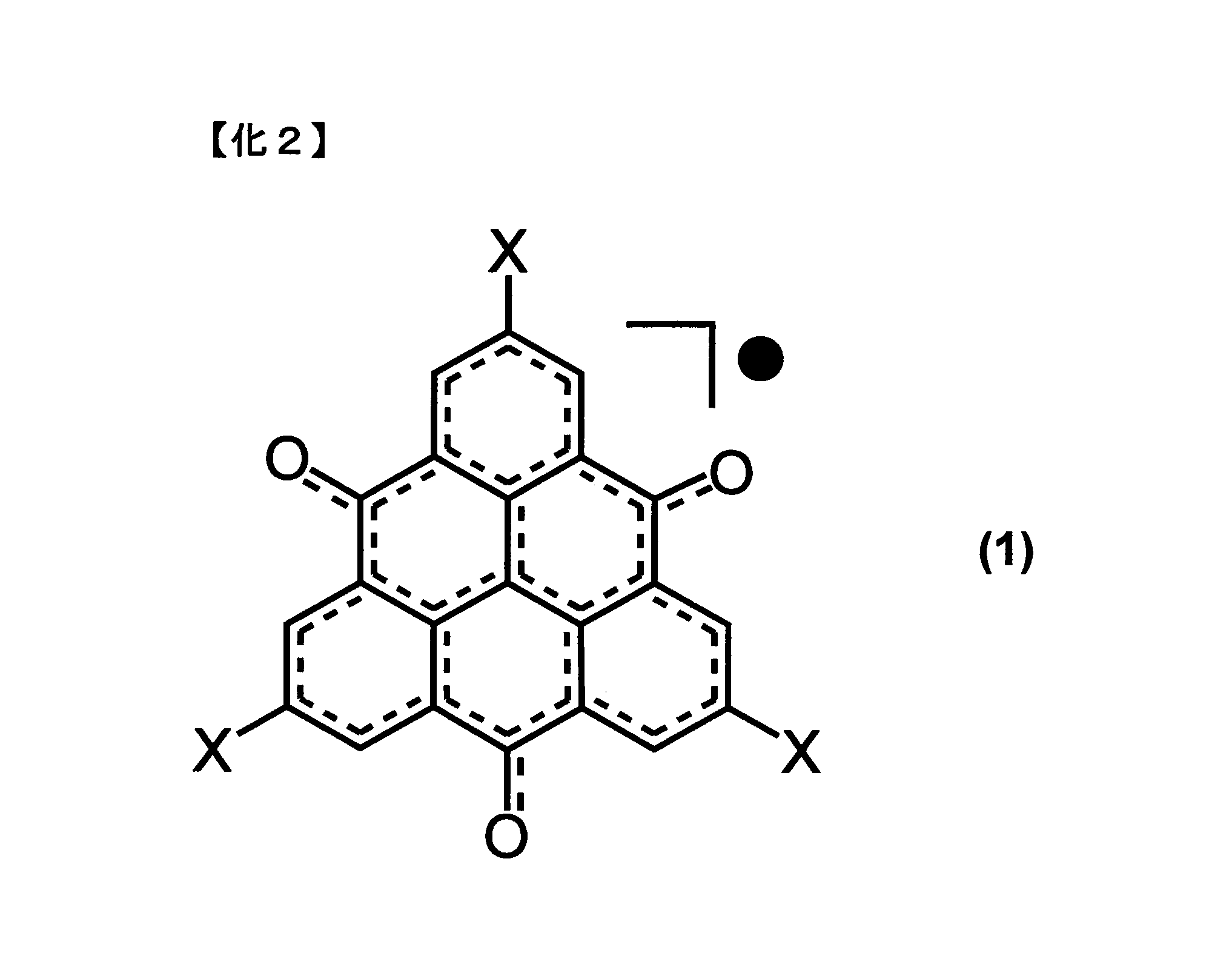
- this invention relates to the electrode sheet used for the non-aqueous electrolyte secondary battery containing the trioxo triangulene (TOT) derivative shown by Formula (1), and a carbon nanotube (CNT; carbon nanotube).
- TOT trioxo triangulene
- CNT carbon nanotube
- non-aqueous electrolyte secondary battery having a large charge and discharge capacity, excellent in safety, and excellent in high-speed charge and discharge characteristics and cycle characteristics.
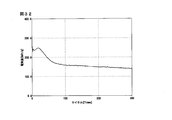
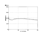
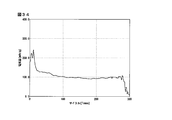
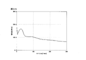
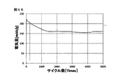
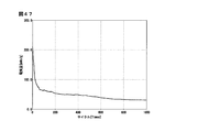
- FIG. 21 is a graph showing a change in discharge capacity with respect to the number of charge and discharge cycles of the lithium ion secondary battery according to Example 9. It is a graph which shows the change of the discharge capacity with respect to the charge / discharge cycle number of the lithium ion secondary battery which concerns on Example 10.
- Example 15 is a graph showing a change in discharge capacity with respect to the number of charge and discharge cycles of the lithium ion secondary battery according to Example 11.
- 21 is a graph showing a change in discharge capacity with respect to the number of charge and discharge cycles of the lithium ion secondary battery according to Example 12.
- 21 is a graph showing a change in discharge capacity with respect to the number of charge and discharge cycles of the lithium ion secondary battery according to Example 13. It is a graph which shows the change of the discharge capacity with respect to the charge / discharge cycle number of the lithium ion secondary battery which concerns on Example 14.
- FIG. 21 is a graph showing a change in discharge capacity with respect to the number of charge and discharge cycles of the lithium ion secondary battery according to Example 15.
- FIG. 21 is a graph showing a change in discharge capacity with respect to the number of charge and discharge cycles of the lithium ion secondary battery according to Example 19. It is a graph which shows the change of the discharge capacity with respect to the charge / discharge cycle number of the lithium ion secondary battery which concerns on Example 20.
- 21 is a graph showing a change in discharge capacity with respect to the number of charge and discharge cycles of the lithium ion secondary battery according to Example 21. It is a graph which shows the change of the discharge capacity with respect to the charge / discharge cycle number of the lithium ion secondary battery which concerns on Example 22.
- FIG. 33 is a graph showing a change in discharge capacity with respect to the number of charge and discharge cycles of the lithium ion secondary battery according to Example 23.
- FIG. It is a graph which shows the change of the discharge capacity with respect to the charge / discharge cycle number of the lithium ion secondary battery which concerns on Example 24.
- 21 is a graph showing a change of discharge capacity with respect to the number of charge and discharge cycles of the lithium ion secondary battery according to Example 25.
- Example 30 It is a graph which shows the change of the discharge capacity with respect to the charge / discharge cycle number of the lithium ion secondary battery which concerns on Example 30.
- 21 is a graph showing a change in discharge capacity with respect to the number of charge and discharge cycles of the lithium ion secondary battery according to Example 31. It is a graph which shows the change of the discharge capacity with respect to the charge / discharge cycle number of the lithium ion secondary battery which concerns on Example 32.
- FIG. It is a graph which shows the change of the discharge capacity with respect to the charge / discharge cycle number of the lithium ion secondary battery which concerns on Example 33.
- FIG. It is a graph which shows the change of the discharge capacity with respect to the charge / discharge cycle number of the lithium ion secondary battery which concerns on Example 34.
- 51 is a graph showing a change in discharge capacity with respect to the number of charge and discharge cycles of the lithium ion secondary battery according to Example 40.
- 51 is a graph showing a change of discharge capacity with respect to the number of charge and discharge cycles of the lithium ion secondary battery according to Example 41. It is a graph which shows the change of the discharge capacity with respect to the charge / discharge cycle number of the lithium ion secondary battery which concerns on Example 42.
- FIG. 51 is a graph showing a change of discharge capacity with respect to the number of charge and discharge cycles, of the lithium ion secondary battery according to Example 43. It is a graph which shows the change of the discharge capacity with respect to the charge / discharge cycle number of the lithium ion secondary battery which concerns on Example 44.
- Example 51 is a graph showing a change in discharge capacity with respect to the number of charge and discharge cycles of the lithium ion secondary battery according to Example 45. It is a graph which shows the change of the discharge capacity with respect to the charge / discharge cycle number of the lithium ion secondary battery which concerns on Example 46. FIG. It is a graph which shows the change of the discharge capacity with respect to the charge / discharge cycle number of the lithium ion secondary battery which concerns on Example 47.
- the electrode sheet used for the non-aqueous electrolyte secondary battery according to one embodiment of the present invention is composed of the TOT derivative represented by the formula (1) and CNT (carbon nanotube).
- X is hydrogen, halogen, or a monovalent organic group, and may be the same or different
- X is, for example, an alkyl group, an aryl group, an aralkyl group, a carboxyl group, an alkoxycarbonyl group, an amino group, a hydroxyl group, an acyl group And a nitro group or a cyano group.
- halogen an alkyl group having 6 or less carbon atoms or aryl group is preferable as X, and the molecular weight is most Small hydrogen is most preferred.
- the halogen may be bromine (Br).
- CNTs are used as a conductive aid to form a conductive network.
- the CNT has a structure in which a graphene sheet is rolled into a cylindrical shape.
- the diameter of the cylinder of CNT used in the embodiment of the present invention is preferably 1 nm to 50 nm.
- the CNTs include single-walled single-walled CNTs and multi-walled CNTs having a multi-walled structure, any of which can be applied to the present invention.
- multi-walled CNTs are preferred in consideration of cost.
- the aspect ratio (length / diameter ratio) of the cylinder is preferably 10 or more, more preferably 100 or more, from the viewpoint of the conductive network formation efficiency.
- the electrode sheet for a non-aqueous electrolyte secondary battery used in the embodiment of the present invention may or may not contain a binder, but preferably does not contain a binder from the viewpoint of improving the charge capacity per unit.
- a binder such as polyvinylidene fluoride (PVdF) or polytetrafluoroethylene (PTFE) is contained in the electrode active material of the non-aqueous electrolyte secondary battery for the ease of formation of the electrode sheet.
- PVdF polyvinylidene fluoride
- PTFE polytetrafluoroethylene
- the formability of the electrode sheet is lowered even if the binder sheet is not contained or the binder content is lowered than the binder content adopted for general non-aqueous electrolyte secondary batteries.
- an electrode sheet having a large charge / discharge capacity per unit volume of battery and per unit weight can be obtained.
- the electrode sheet can be formed because the formability of the electrode active material is increased by the entanglement of the CNTs. it is conceivable that.
- the electrode sheet for a non-aqueous electrolyte secondary battery used in the embodiment of the present invention is produced by forming an electrode active material composed of CNT and a TOT derivative into a sheet form.
- the electrode sheet in which the CNT is mixed with the TOT derivative can be expected to smoothly transfer electrons between the CNT-TOT derivative by the ⁇ - ⁇ interaction between the CNT and the TOT derivative which is a condensed polycyclic benzenoid derivative. At the same time, entanglement of CNTs can be expected to form an electrical conduction path.
- this ⁇ - ⁇ interaction has an effect of capturing the TOT derivative molecule, it is possible to suppress the elution of the TOT derivative into the electrolytic solution. This elution suppression can improve the cycle characteristics of the battery.
- the TOT is sufficiently diffused into the CNT network, that is, its dispersibility, for efficient electrical conduction and electron transfer.
- the TOT derivative and CNT are stirred and mixed in a solid state or in the presence of a small amount of solvent using a mortar, ball mill, homogenizer, mixer or the like. Alternatively, both are dispersed in a solvent and stirred and mixed using a stirring device, an ultrasonic irradiation device, a shaker, Filmix (registered trademark) or the like.
- a method of dispersing in a solvent and stirring and mixing is preferable, and at that time, it is more preferable to perform ultrasonic irradiation.
- the solvent to be used is not particularly limited, and methanol, ethanol, isopropanol, toluene, N-methylpyrrolidone, dimethylformamide, dimethyl sulfoxide, dimethyl carbonate, diethyl carbonate, propylene carbonate and the like can be mentioned.
- a solvent having a boiling point of 100 ° C. or less is preferable because it requires only a short time of drying after electrode sheet production, and methanol, ethanol and isopropanol are more preferable among them in terms of cost.
- one example is a method in which a dispersion of a TOT derivative and CNTs is filtered little by little with a filter to accumulate residues. Be This filtration method is preferred in terms of simplicity.
- the filter to be filtered is not particularly limited, but it is preferable to use a membrane filter for the purpose of preventing CNTs from leaking into the filtrate through the filter. It is more preferable to vacuum filter the membrane filter particularly in view of time efficiency.
- the pore size of the membrane filter is preferably in the range of 0.05 ⁇ m to 3 ⁇ m. If it is smaller than this, filtration takes time, and if it is larger, some CNTs leak into the filtrate.
- the thickness per layer is preferably in the range of 0.1 ⁇ m to 10 ⁇ m, and more preferably in the range of 0.1 ⁇ m to 2 ⁇ m, from the balance of dispersibility and time efficiency.
- the thickness per layer is 1 ⁇ m, it may be filtered 100 times to produce an electrode sheet with a thickness of 100 ⁇ m.
- stacked on multiple layers is obtained.
- the sheet is dried before being incorporated into the non-aqueous electrolyte secondary battery.
- a lithium ion secondary battery is mentioned as a non-aqueous electrolyte secondary battery concerning the embodiment of the present invention.
- an electrode sheet containing the TOT derivative and CNTs is brought into contact with one side of a current collector and molded to form a positive electrode, which is opposed to the negative electrode via a separator, and non-aqueous electrolysis is carried out between the electrodes It can be produced by filling and sealing a liquid.
- the current collector is made of a thin plate of aluminum, copper, nickel, iron, stainless steel or the like.
- the electrode sheet In order to bring the electrode sheet into contact with one surface of the current collector, it may be brought into pressure contact using a press, or may simply be brought into contact without pressure.
- lithium As the negative electrode, lithium, a lithium-containing alloy, a lithium-carbon composite material, etc. can be used. Lithium-carbon composite materials are preferable in that they can suppress side reactions on the negative electrode and have excellent cycle characteristics, and a pre-doped negative electrode in which lithium is inserted in advance in graphite is more preferable (see Patent Document 3).
- the pre-doped negative electrode can be prepared by bringing the graphite formed into a sheet into contact with lithium metal in an electrolytic solution.
- the non-aqueous electrolytic solution is not particularly limited, and for example, one in which a lithium salt is dissolved in a solvent can be used.
- lithium salts include lithium hexafluorophosphate, lithium tetrafluoroborate, lithium bis (trifluoromethanesulfonylimide), lithium trifluoromethanesulfonate, lithium bis (fluorosulfonyl) imide and the like.
- the solvent include propylene carbonate, ethylene carbonate, vinylene carbonate, dimethyl carbonate, diethyl carbonate, and mixtures thereof.
- the electrode sheet of the non-aqueous electrolyte secondary battery according to the embodiment of the present invention may be used as a negative electrode.
- high-potential compounds such as LiNi 0.5 Mn 1.5 O 4 , Li 2 CoPO 4 F, FeF 3 , NaFeF 3 , FeOF and the like can be used as the positive electrode active material to be combined.
- a lithium ion secondary battery is described as a non-aqueous electrolyte secondary battery according to an embodiment of the present invention
- the present invention is directed to, for example, a sodium ion secondary battery, a magnesium ion secondary battery, or an aluminum ion secondary battery It can be adopted other than the lithium ion secondary battery.
- Bromine substituted TOT (Br 3 TOT) was synthesized by the method described in Non-Patent Document 1.
- unsubstituted TOT (H 3 TOT) was synthesized in the same manner as Br 3 TOT, using 2-iodotoluene as a starting material.
- the film thickness of the electrode sheet was measured using a length gauge MT1281 manufactured by HEIDENHAIN. Multilayer CNT was purchased from Meijo Nano Carbon Co., Ltd.
- the aspect ratio was 100 to 1000.
- Example 1 (Production of H 3 TOT Lithium Ion Secondary Battery)>
- 2.52 g of multi-walled CNT 1 wt% ethanol dispersion 2.8 mg of H 3 TOT was added and stirred for 1 hour while being irradiated with ultrasonic waves.
- the mixed dispersion thus obtained was divided into 50 equal parts, and each divided mixed liquid was filtered under reduced pressure through a membrane filter with a pore size of 0.2 ⁇ m, and 50 layers were stacked on the filter. The stacked filtrate was then dried at 70 ° C./90 minutes.
- a CNT buckypaper (Buckypaper) positive electrode sheet in which H 3 TOTs were dispersed was produced.
- the film thickness of the positive electrode sheet thus obtained was 69 ⁇ m.
- the H 3 TOT content in this positive electrode sheet is 10 wt%.
- the positive electrode sheet was dried under reduced pressure at 80 ° C. for 12 hours before battery preparation.
- a lithium ion secondary battery was manufactured as follows using the positive electrode sheet obtained in this manner. First, the battery shape was CR2032. And negative electrode side exterior, stainless metal plate (negative electrode current collector), lithium foil (negative electrode), separator of porous film made of polypropylene, the positive electrode sheet (positive electrode), stainless metal plate (positive electrode current collector), spring, positive electrode side The exteriors were stacked in this order. Thereafter, an electrolytic solution was put into the inside of the outer package, and then the outer package was crimped to obtain a lithium ion secondary battery.
- This battery was set in a TOSCAT-3100 charge / discharge tester manufactured by Toyo Systems Co., Ltd., and charge / discharge was repeated at a voltage range of 1.4 to 3.8 V and a current amount of 1C.
- the discharge capacity per weight of H 3 TOT with respect to the number of charge and discharge cycles is shown in FIG. According to FIG. 1, it can be seen that a discharge capacity comparable to the theoretical capacity 334 mAh / g is maintained for 200 cycles or more.
- Preparation of pre-doped negative electrode sheet> After mixing 540 mg of powdered graphite, 1.2 g of a 5 wt% N-methylpyrrolidone solution of polyvinylidene fluoride, and 0.3 mL of N-methyl pyrrolidone and stirring with a planetary stirrer for 10 minutes, a bar coater with a clearance of 30 ⁇ m is used. The resultant was cast on a copper plate and dried under reduced pressure at 120 ° C. for 1 hour. This was pressed with a roll press at a pressure of 800 kg / cm 2 to produce a negative electrode sheet.
- the lithium ion was inserted into the negative electrode sheet by bringing the negative electrode sheet and the lithium foil into contact with each other in the electrolytic solution to prepare a pre-doped negative electrode.
- Ethylene carbonate / diethyl carbonate LiPF 6 at a concentration of 1.0M as an electrolytic solution (volume ratio of 3: 7) was used dissolved in.
- Example 2 to Example 28 (Production of H 3 TOT Lithium Ion Secondary Battery)> A positive electrode sheet was produced using H 3 TOT in the same manner as in Example 1, and a lithium ion secondary battery was produced and evaluated in the same manner as in Example 1 using a lithium foil or the above-prepared pre-doped negative electrode as a negative electrode. .
- Examples 2 to 25 used a charge / discharge tester TOSCAT-3100 manufactured by Toyo Systems Co., Ltd. as a charge / discharge tester as in Example 1, but Example 26 used a VMP- of Biologic Science Instruments.
- Example 3 and Example 28 used 3M, and TOSCAT-3300 of Toyo Systems Co., Ltd., respectively.
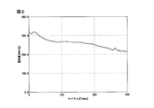
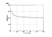
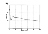
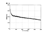
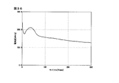
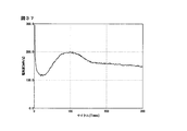
- FIGS. 1 to 28 Graphs showing the respective discharge capacities are shown in FIGS. 1 to 28. Comparison of FIG. 1 to FIG. 5 (lithium foil negative electrode) and FIG. 6 to FIG. 10 (pre-doped negative electrode) at the charge / discharge speed of 1 C shows that both the discharge capacity and the cycle characteristics are excellent when the pre-doped negative electrode is used. This tendency is the same as in the case where the charge and discharge rate is increased (FIGS. 11 to 28).
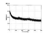
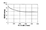
- the secondary battery of the present invention maintains a discharge capacity of 175 mAh / g after 5000 cycles even under high-speed charge and discharge conditions of 100 C, and is found to be excellent in high-speed charge and discharge characteristics and cycle characteristics (FIG. 26). Furthermore, the capacity of 100 mAh / g is shown after 5000 cycles under the condition of 300 C (FIG. 28).
- the SEM cross-sectional image of the positive electrode sheet of Example 11 is shown in FIG. In FIG. 29, the left side is a low magnification image and the right side is a high magnification image.
- the low magnification image shows that the CNTs are layered, and the high magnification image shows that the particulate TOT adheres to the layered CNTs.
- Examples 29 to 40 (Production of Br 3 TOT Lithium Ion Secondary Battery)> A positive electrode sheet is prepared in the same manner as in Example 1 using Br 3 TOT instead of H 3 TOT, and a lithium ion secondary battery is manufactured in combination with a lithium foil or a pre-doped negative electrode, and charge / discharge test by Toyo Systems Co., Ltd. Charge and discharge evaluation was performed using the machine TOSCAT-3100. The details of the preparation conditions and the charge / discharge conditions are shown in Table 2, and the measured discharge characteristics are shown in FIGS. 30 to 41. In the case of Br 3 TOT also, the decrease in discharge capacity was observed as the content was increased, but good cycle characteristics were shown also at the charge and discharge rate of 20 C.
- Example 41 to Example 47 Manufacture of H 3 TOT Lithium Ion Secondary Battery> A positive electrode sheet was produced in the same manner as in Example 1 using H 3 TOT, and combined with a pre-doped negative electrode to produce a lithium ion secondary battery. At this time, in Examples 43, 45 and 47, 2.0 M LiPF 6 was used as the electrolyte, and the other 1.0 M LiPF 6 was used. Further, ethylene carbonate / diethyl carbonate (volume ratio 1: 1) in Examples 41, 46 and 47, ethylene carbonate / diethyl carbonate (volume ratio 3: 7) in Examples 43 and 45 as electrolyte solvent, Examples 42 and 44 Used ethylene carbonate / dimethyl carbonate (volume ratio 3: 7).
- Examples 41 to 43, 46 and 47 used charge and discharge tester TOSCAT-3100 manufactured by Toyo Systems Co., Ltd., and Examples 44 and 45 used the same TOSCAT-3300.
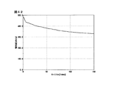
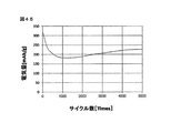
- the details of the preparation conditions and the charge and discharge conditions are shown in Table 3, and the discharge characteristics are shown in FIGS. 42 to 48.
Landscapes
- Chemical & Material Sciences (AREA)
- Chemical Kinetics & Catalysis (AREA)
- Electrochemistry (AREA)
- General Chemical & Material Sciences (AREA)
- Engineering & Computer Science (AREA)
- Materials Engineering (AREA)
- Manufacturing & Machinery (AREA)
- Inorganic Chemistry (AREA)
- Battery Electrode And Active Subsutance (AREA)
- Secondary Cells (AREA)
Abstract
充放電容量が大きく安全性に優れ、高速充放電特性およびサイクル特性も良好な非水電解質二次電池のための電極シートを提供する。電極シートは積層状であり、各層には、トリオキソトリアンギュレン(TOT)誘導体が、カーボンナノチューブ(CNT)の中に分散されている。
Description
本発明は非水電解質二次電池に用いる電極シートおよびそれを用いた非水電解質二次電池に関するものである。
リチウムイオン二次電池などに代表される非水電解質二次電池は、エネルギー密度が大きく高容量であることからモバイル機器の電源や電気自動車用バッテリーなどに広く実用化されている。
現在ではリチウムイオン二次電池の電極活物質として、コバルト酸リチウムなどの金属酸化物が主に使用されている。このようなコバルト酸リチウムなどの金属酸化物を電極活物質として使用するリチウムイオン二次電池では、充電時に電極活物質からリチウムイオンが一定量以上抜けてしまうとその結晶構造が崩壊して酸素を発生しながら発熱し、電池が発火するという問題があった。またコバルトは希少元素であるためコストや入手性にも問題があった。
このような安全性、コスト、入手性に関する問題を解決する手段として、有機化合物を電極活物質として利用する技術が提案されている。例えば特許文献1には安定有機ラジカルポリマーを電極活物質とするリチウムイオン二次電池が記載されている。特許文献1には、このような安定有機ラジカルポリマーとして、ニトロキシルラジカルを有するポリマー、オキシラジカルを有するポリマー、窒素ラジカルを有するポリマーが記載されているが、電極活物質1ユニットあたりの充放電に関与する電子数が少ないため、電池の充放電容量が小さいという問題があった。
二次電池の充放電容量を向上させる試みとして、特許文献2には1ユニットあたり2以上の電子が関与する酸化還元反応が可能な有機化合物が提案されている。このような化合物として、特許文献2では正極活物質としてフェナレニル骨格を有する有機化合物をあげている。このフェナレニル骨格を有する有機化合物、導電助剤およびバインダーを用いて電極シートが作製される。しかしこの電極シートを用いて作製した二次電池は放電容量が最大165mAh/gであり、その数値を評価すると、当該電極シートを用いて作製した二次電池は、従来の金属酸化物を用いる電池と比較してほぼ同等の性能でしかなかった。
前記有機化合物として有機ラジカル化合物を用いた高容量のリチウムイオン二次電池を製造するための試みとして、非特許文献1にトリオキソトリアンギュレン(TOT;Trioxotriangulene)誘導体を電極活物質とする例が開示されている。
TOT誘導体は、巨大なπ電子系を有する縮合多環型の分子構造を有し、電子スピンが分子骨格全体に広く非局在化している中性ラジカル化合物である。ここで「スピン局在」とは、分子骨格の一部に電子スピンが局在化している構造をいい、「スピン非局在」とは、電子スピンが分子骨格全体に広く分布している構造を言う。TOT誘導体の一例として、下記式(1)のXをtert-ブチル基で置換したtert-ブチル基置換体がある。
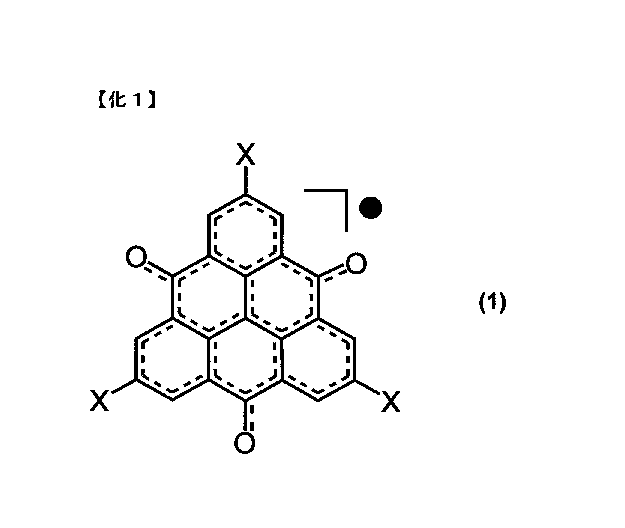
非特許文献1によれば、tert-ブチル基置換体を電極活物質とした場合に0.3Cでの初回充放電容量が311mAh/gと大きな値が出ているが、2サイクル目では169mAh/gと低下しており、サイクル安定性が満足いくものではなかった。また充放電速度は最大2Cであり、高速充放電特性にも問題があった。
ここで充放電速度の尺度として用いるCとは、電池の充電または放電にn時間を要する電流値をC/nと定義する単位である。すなわち1Cとは充電または放電に1時間を要する電流値であり、実際の充放電試験では電極活物質の理論容量を基準に設定される。
Yasushi Morita, et. al.,"Organic tailored batteries materials using stable open-shell molecules with degenerate frontier orbitals", Nature Materials 10, 947-951 (2011)
本願は、充放電容量が大きく安全性に優れ、高速充放電特性およびサイクル特性も良好な非水電解質二次電池に用いる電極シートおよび非水電解質二次電池を提供することを課題とする。
本発明者は、電極活物質として単位重量あたりの関与電子数がなるべく大きなものを開発し、さらに電極から充放電に不要な物質を排除することを試みた。これにより電池単位体積あたりおよび単位重量あたりの充放電容量の最大化が可能であることを見出した。また高速充放電を実現するために、新規の電気伝導率の高い材料、および構造を見出した。
すなわち本願発明は、式(1)で示されるトリオキソトリアンギュレン(TOT)誘導体と、カーボンナノチューブ(CNT;carbon nanotube)とを含む非水電解質二次電池に用いる電極シートに関する。

(式中、Xは水素、ハロゲン、1価の有機基であり、互いに同一でも異なっていても良い)
更に、前記式(1)で示されるトリオキソトリアンギュレン誘導体と、カーボンナノチューブとを溶媒に分散させた後、当該分散液を2回以上濾過し、濾過後の残渣を乾燥させて、2以上の層からなる電極シートとする、非水電解質二次電池に用いる電極シートの製造方法を開発した。
更に、前記式(1)で示されるトリオキソトリアンギュレン誘導体と、カーボンナノチューブとを溶媒に分散させた後、当該分散液を2回以上濾過し、濾過後の残渣を乾燥させて、2以上の層からなる電極シートとする、非水電解質二次電池に用いる電極シートの製造方法を開発した。
本発明によれば、充放電容量が大きく安全性に優れ、高速充放電特性およびサイクル特性も良好な非水電解質二次電池を提供することができる。
本発明における上述の、またはさらに他の利点、特徴および効果は、添付図面を参照して次に述べる実施形態の説明により明らかにされる。
以下に本発明の実施の形態を説明するが、本発明はここに開示される各実施の形態に限定されるものでない。本発明の範囲は特許請求の範囲によって示され、特許請求の範囲と均等の意味および範囲内でのすべての変更および類似の構造が含まれる。
<電極シート>
本発明の一実施形態に係る非水電解質二次電池に用いる電極シートは、式(1)で示されるTOT誘導体と、CNT(carbon nanotube)とから構成される。
本発明の一実施形態に係る非水電解質二次電池に用いる電極シートは、式(1)で示されるTOT誘導体と、CNT(carbon nanotube)とから構成される。
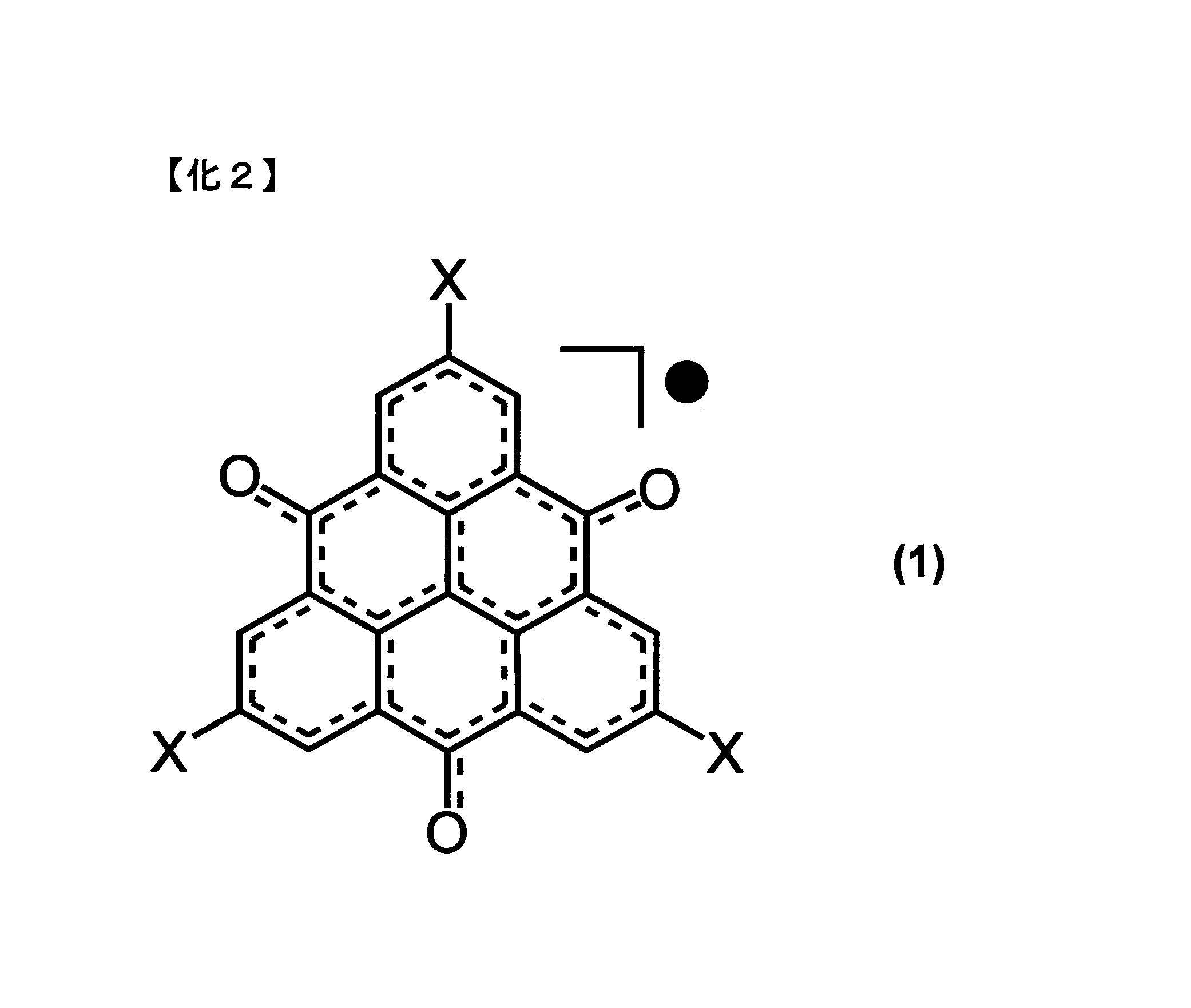
(式中、Xは水素、ハロゲン、または1価の有機基であり、互いに同一でも異なっていても良い)
前記式(1)のTOT誘導体において、Xが1価の有機基である場合、Xとしては例えば、アルキル基、アリール基、アラルキル基、カルボキシル基、アルコキシカルボニル基、アミノ基、ヒドロキシル基、アシル基、ニトロ基、またはシアノ基などがあげられる。Xの分子量が小さいほうが電池単位体積あたりおよび単位重量あたりの充放電容量を大きくできるので、この観点から、Xとしては水素、ハロゲン、炭素数6以下のアルキル基またはアリール基が好ましく、分子量の最も小さい水素が最も好ましい。ハロゲンを選んだ場合、前記ハロゲンは臭素(Br)であってもよい。
前記式(1)のTOT誘導体において、Xが1価の有機基である場合、Xとしては例えば、アルキル基、アリール基、アラルキル基、カルボキシル基、アルコキシカルボニル基、アミノ基、ヒドロキシル基、アシル基、ニトロ基、またはシアノ基などがあげられる。Xの分子量が小さいほうが電池単位体積あたりおよび単位重量あたりの充放電容量を大きくできるので、この観点から、Xとしては水素、ハロゲン、炭素数6以下のアルキル基またはアリール基が好ましく、分子量の最も小さい水素が最も好ましい。ハロゲンを選んだ場合、前記ハロゲンは臭素(Br)であってもよい。
本発明の実施形態では導電ネットワーク形成のために、導電助剤としてCNTを利用する。CNTは、グラフェンシートを円筒状に丸めた構造を有している。
本発明の実施形態で使用するCNTの円筒の直径は好ましくは1nmから50nmである。
CNTには、円筒が単層(single wall)の単層CNTと、多層(multi wall)の構造を形成した多層CNTとがあるが、いずれも本発明に適用することができる。特にコストを考慮して多層CNTが好ましい。
また導電ネットワーク形成効率の点で、円筒のアスペクト比(長さ/直径比)は10以上が好ましく、100以上がより好ましい。
本発明の実施形態で使用する非水電解質二次電池用電極シートは、バインダーを含んでいても含んでなくてもよいが、単位あたりの充電容量向上の観点からバインダーを含まないのが好ましい。通常、非水電解質二次電池の電極活物質には、電極シートの成形のしやすさのため、ポリフッ化ビニリデン(PVdF)、ポリテトラフルオロエチレン(PTFE)などのバインダーを含有させるが、このバインダーは充放電に寄与しない物質のため、電池単位体積あたりおよび単位重量あたりの充放電容量の低下を招く原因の一つとなっている。本発明の電極シートでは、バインダーを含まなくても、あるいはバインダーの含有量を一般の非水電解質二次電池に採用されるバインダーの含有量より低下させても、電極シートの成形性が低下せず、電池単位体積あたりおよび単位重量あたりの充放電容量の大きな電極シートを得ることができる。
なお、本発明の実施形態においてバインダーの含有量が少なくても、あるいは含有量が0でも電極シートを成形できる理由は、CNT同士が絡みあうことにより、電極活物質の成形性が増すためであると考えられる。
本発明の実施形態で使用する非水電解質二次電池用電極シートは、CNTとTOT誘導体とから構成される電極活物質を、シートの形に成形して作製する。
TOT誘導体にCNTを混合した電極シートは、CNTと、縮合多環ベンゼノイド誘導体であるTOT誘導体とのπ-π相互作用により、CNT-TOT誘導体間の電子の授受がスムーズに行えると期待できる。それと共に、CNT同士の絡み合いにより電気伝導パスを形成することが期待できる。
さらにこのπ-π相互作用はTOT誘導体分子を捕捉する効果があるため、TOT誘導体の電解液への溶出を抑制することが可能である。この溶出抑制により電池のサイクル特性を向上させることができる。
効率のよい電気伝導および電子の授受にはCNTネットワーク中へTOTが十分に拡散していること、すなわち分散性が重要である。
TOTの分散性を上げるためにはCNTとTOT誘導体とを混合してシート化する際、CNTとTOT誘導体とが薄い層を成して、それが繰り返し積層されるように作製することが有効である。薄層状に積層されていると、たとえ一層のレベルでCNTとTOTが分離したとしても積層膜全体では成分の均一性が高くなり、電極の電気伝導率の向上と電池の容量の向上が見込まれるからである。
このため、以下のような電極シートの製造方法が最適である。
<電極シートの製造方法>
TOT誘導体とCNTとを固体状態のまま、あるいは少量の溶媒の存在下で乳鉢、ボールミル、ホモジナイザー、ミキサーなどで撹拌混合する。または、両者を溶媒に分散させて撹拌装置、超音波照射装置、シェイカー、フィルミックス(登録商標)などを用いて撹拌混合する。
TOT誘導体とCNTとを固体状態のまま、あるいは少量の溶媒の存在下で乳鉢、ボールミル、ホモジナイザー、ミキサーなどで撹拌混合する。または、両者を溶媒に分散させて撹拌装置、超音波照射装置、シェイカー、フィルミックス(登録商標)などを用いて撹拌混合する。
TOT誘導体とCNTの混合を効率よく行える点で、溶媒に分散させて撹拌混合する方法が好ましく、その際に超音波照射を施すことがより好ましい。
使用する溶媒としては特に限定されないが、メタノール、エタノール、イソプロパノール、トルエン、N-メチルピロリドン、ジメチルホルムアミド、ジメチルスルホキシド、ジメチルカーボネート、ジエチルカーボネート、プロピレンカーボネートなどをあげることができる。電極シート作製後の乾燥工程が短時間で済む点から沸点100℃以下の溶媒が好ましく、その中でもコストの点でメタノール、エタノール、イソプロパノールがより好ましい。
このようにしてTOT誘導体とCNTとの分散液を調製する。
CNTが層状に積層された電極シートを作製するための方法として、様々な方法を採用できるが、一例として、TOT誘導体とCNTの分散液をフィルターで少量ずつ濾過して残渣を蓄積させる方法が挙げられる。この濾過する方法は簡便性の点で好ましい。
濾過するフィルターは特に限定されないが、CNTがフィルターを通過して濾液に漏れ出ることを防ぐ目的でメンブレンフィルター(membrane filter)を用いることが好ましい。特に時間効率の点でメンブレンフィルターを減圧濾過することがより好ましい。メンブレンフィルターの孔径は0.05μm~3μmの範囲が好ましい。これより小さいと濾過に時間がかかってしまい、大きいと一部のCNTが濾液に漏れ出してしまう。
TOT誘導体とCNTとの分散液を少量供給し、供給された分散液を濾過して、薄い残渣をフィルター上に残す。そしてフィルター上の残渣の上から再度分散液を少量供給する。これを2回以上繰り返していくと、(一度の濾過で得られた一層の厚さ)×(濾過回数)の厚さを持つ、2以上の層に積層された層ができる。この一層の厚さが薄いほどTOT誘導体の分散性が向上すると考えられるが、薄くすると濾過の回数が増え、時間がかかってしまう。したがって分散性と時間効率との兼ね合いから一層あたりの厚さは0.1μm~10μmの範囲が好ましく、0.1μm~2μmの範囲がより好ましい。
例えば、一層あたりの厚さが1μmであれば、厚さ100μmの電極シートを作製するためには、100回濾過すればよい。
以上のようにすることで、複数層に積層された電極シートが得られる。
当該シートは、非水電解質二次電池に組み込む前に、乾燥させる。残存溶媒の影響を除去するため、加熱しながら減圧乾燥して、溶媒を完全に除去することが好ましい。
<非水電解質二次電池>
本発明の実施形態にかかる非水電解質二次電池として、リチウムイオン二次電池が挙げられる。リチウムイオン二次電池は、前記TOT誘導体とCNTとを含む電極シートを集電体の一面に接触させて成形して正極とし、それをセパレータを介して負極に対向させ、電極間に非水電解液を満たして封止することによって作製することができる。
本発明の実施形態にかかる非水電解質二次電池として、リチウムイオン二次電池が挙げられる。リチウムイオン二次電池は、前記TOT誘導体とCNTとを含む電極シートを集電体の一面に接触させて成形して正極とし、それをセパレータを介して負極に対向させ、電極間に非水電解液を満たして封止することによって作製することができる。
前記集電体はアルミニウム、銅、ニッケル、鉄、ステンレスなどの薄板でできている。
前記電極シートと集電体の一面に接触させるには、プレス機を用いて加圧密着させてもよく、加圧せずに単に接触させるだけでも良い。
前記負極としては、リチウム、リチウム含有合金、リチウム-炭素複合材料などを用いることができる。負極での副反応を抑制でき、サイクル特性に優れる点で、リチウム-炭素複合材料が好ましく、グラファイトにあらかじめリチウムを挿入させたプリドープ負極がより好ましい(特許文献3参照)。プリドープ負極は、シート状に成形したグラファイトを電解液中、リチウム金属と接触させることにより調整することができる。
前記非水電解液としては特に限定されないが、例えばリチウム塩を溶媒に溶解させたものを用いることができる。リチウム塩としては例えば六フッ化リン酸リチウム、四フッ化ホウ酸リチウム、リチウムビス(トリフルオロメタンスルホニルイミド)、トリフルオロメタンスルホン酸リチウム、リチウムビス(フルオロスルホニル)イミドなどがあげられる。溶媒としては例えばプロピレンカーボネート、エチレンカーボネート、ビニレンカーボネート、ジメチルカーボネート、ジエチルカーボネート、およびこれらの混合物などがあげられる。
なお、本発明の実施形態にかかる非水電解質二次電池の電極シートは負極に使用してもよい。この場合、組み合わせる正極活物質としては高電位型化合物、例えばLiNi0.5Mn1.5O4、Li2CoPO4F、FeF3、NaFeF3、FeOFなどを使用することができる。
また、本発明の実施形態にかかる非水電解質二次電池としてリチウムイオン二次電池を記載したが、本発明は例えばナトリウムイオン二次電池、マグネシウムイオン二次電池、またはアルミニウムイオン二次電池など、リチウムイオン二次電池以外にも採用できる。
以下、本発明の実施例を記載するが、本発明はこれらの実施例に限定されるものではない。
臭素置換TOT(X=Br;Br3TOT)と無置換TOT(H3TOT)とを合成した。臭素置換TOT(Br3TOT)は非特許文献1に記載の方法によって合成した。また無置換TOT(H3TOT)は2-ヨードトルエンを出発原料として用い、Br3TOTと同様に合成した。電極シートの膜厚はハイデンハイン社製の長さゲージMT1281を用いて測定した。多層CNTは(株)名城ナノカーボンより購入した。そのアスペクト比は100~1000であった。
<実施例1(H3TOTリチウムイオン二次電池の製造)>
多層CNT 1wt%エタノール分散液2.52gに、H3TOT 2.8mgを入れて超音波照射しながら1時間撹拌した。このようにして得られた混合分散液を50等分して、等分した各混合分散液を、それぞれ孔径0.2μmのメンブレンフィルターを通して減圧濾過し、フィルターの上に50層積み重ねた。その後この積み重ねられた濾過物を70℃/90分間乾燥させた。こうしてH3TOTが分散したCNTバッキーペーパー(Buckypaper)正極シートを作製した。
多層CNT 1wt%エタノール分散液2.52gに、H3TOT 2.8mgを入れて超音波照射しながら1時間撹拌した。このようにして得られた混合分散液を50等分して、等分した各混合分散液を、それぞれ孔径0.2μmのメンブレンフィルターを通して減圧濾過し、フィルターの上に50層積み重ねた。その後この積み重ねられた濾過物を70℃/90分間乾燥させた。こうしてH3TOTが分散したCNTバッキーペーパー(Buckypaper)正極シートを作製した。
こうして得られた正極シートの膜厚は69μmであった。この正極シート中のH3TOT含有量は10wt%である。
さらに電池作製前に、正極シートを80℃/12時間減圧乾燥させた。
このようにして得られた正極シートを用いてリチウムイオン二次電池を以下のように製造した。まず電池形状はCR2032とした。そして負極側外装、ステンレス金属板(負極集電体)、リチウム箔(負極)、ポリプロピレン製多孔質膜のセパレータ、前記正極シート(正極)、ステンレス金属板(正極集電体)、バネ、正極側外装をこれらの順に重ねた。その後、外装の内部に電解液を入れ、その後、外装をかしめることによりリチウムイオン二次電池とした。
なお前記電解液としては、LiPF6を1.0Mの濃度でエチレンカーボネート/ジエチルカーボネート(体積比3:7)に溶解させたものを用いた。
この電池を東洋システムズ(株)製充放電試験機TOSCAT-3100にセットし、電圧範囲1.4-3.8V、電流量1C相当で充放電を繰り返した。充放電サイクル回数に対する、H3TOT重量あたりの放電容量を図1に示す。図1によれば、理論容量334mAh/gに匹敵する放電容量が200サイクル以上保たれていることがわかる。
<プリドープ負極シートの作製>
粉末状のグラファイト540mg、ポリフッ化ビニリデンの5wt%N-メチルピロリドン溶液1.2g、N-メチルピロリドン0.3mLを混合して遊星式攪拌機で10分間撹拌させた後、クリアランス30μmのバーコーターを用いて銅板上にキャストし120℃で1時間減圧乾燥した。これをロールプレス機で800kg/cm2の圧力でプレスして負極シートを作製した。
粉末状のグラファイト540mg、ポリフッ化ビニリデンの5wt%N-メチルピロリドン溶液1.2g、N-メチルピロリドン0.3mLを混合して遊星式攪拌機で10分間撹拌させた後、クリアランス30μmのバーコーターを用いて銅板上にキャストし120℃で1時間減圧乾燥した。これをロールプレス機で800kg/cm2の圧力でプレスして負極シートを作製した。
この負極シートとリチウム箔を電解液中接触させることによりリチウムイオンを負極シート中に挿入し、プリドープ負極を作製した。電解液としてLiPF6を1.0Mの濃度でエチレンカーボネート/ジエチルカーボネート(体積比3:7)に溶解させたものを用いた。
<実施例2~実施例28(H3TOTリチウムイオン二次電池の製造)>
実施例1と同様にH3TOTを用いて正極シートを作製し、リチウム箔あるいは前記作製したプリドープ負極を、負極として用いて、実施例1と同様にリチウムイオン二次電池を製造し、評価した。
実施例1と同様にH3TOTを用いて正極シートを作製し、リチウム箔あるいは前記作製したプリドープ負極を、負極として用いて、実施例1と同様にリチウムイオン二次電池を製造し、評価した。
実施例2~25は充放電試験機として、実施例1と同様、東洋システムズ(株)製充放電試験機TOSCAT-3100を使用したが、実施例26はバイオロジック・サイエンス・インスツルメンツ社のVMP-3Mを、実施例27および実施例28は東洋システムズ(株)のTOSCAT-3300をそれぞれ使用した。
作製条件および充放電条件を表1に示す。

それぞれの放電容量を示すグラフを図1~図28に掲げる。充放電速度1Cにおいて、図1~図5(リチウム箔負極)と図6~図10(プレドープ負極)とを比較すると、プレドープ負極を用いた場合に放電容量、サイクル特性ともに優れることがわかる。この傾向は充放電速度を大きくした場合(図11~図28)においても同様である。本発明の二次電池は100Cという高速充放電条件でも5000サイクル後に175mAh/gの放電容量を維持しており、高速充放電特性とサイクル特性に優れることがわかる(図26)。さらに300Cの条件でも5000サイクル後に100mAh/gの容量を示している(図28)。
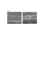
また実施例11の正極シートのSEM断面像を図29に示す。図29において、左側が低倍率像、右側が高倍率像である。低倍率像からCNTが層状に積層されている様子が認められ、高倍率像より層状のCNTに粒子状のTOTが付着している様子が認められる。
<実施例29~実施例40(Br3TOTリチウムイオン二次電池の製造)>
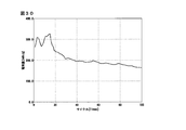
H3TOTの代わりにBr3TOTを用いて実施例1と同様に正極シートを作製し、リチウム箔またはプリドープ負極と組合せてリチウムイオン二次電池を製造し、東洋システムズ(株)製充放電試験機TOSCAT-3100を用いて充放電評価を実施した。作製条件および充放電条件の詳細を表2に、測定した放電特性を図30~図41に示す。Br3TOTの場合もその含有量を増加させるに伴って放電容量の低下が認められるが、20Cの充放電速度においても良好なサイクル特性を示した。
H3TOTの代わりにBr3TOTを用いて実施例1と同様に正極シートを作製し、リチウム箔またはプリドープ負極と組合せてリチウムイオン二次電池を製造し、東洋システムズ(株)製充放電試験機TOSCAT-3100を用いて充放電評価を実施した。作製条件および充放電条件の詳細を表2に、測定した放電特性を図30~図41に示す。Br3TOTの場合もその含有量を増加させるに伴って放電容量の低下が認められるが、20Cの充放電速度においても良好なサイクル特性を示した。
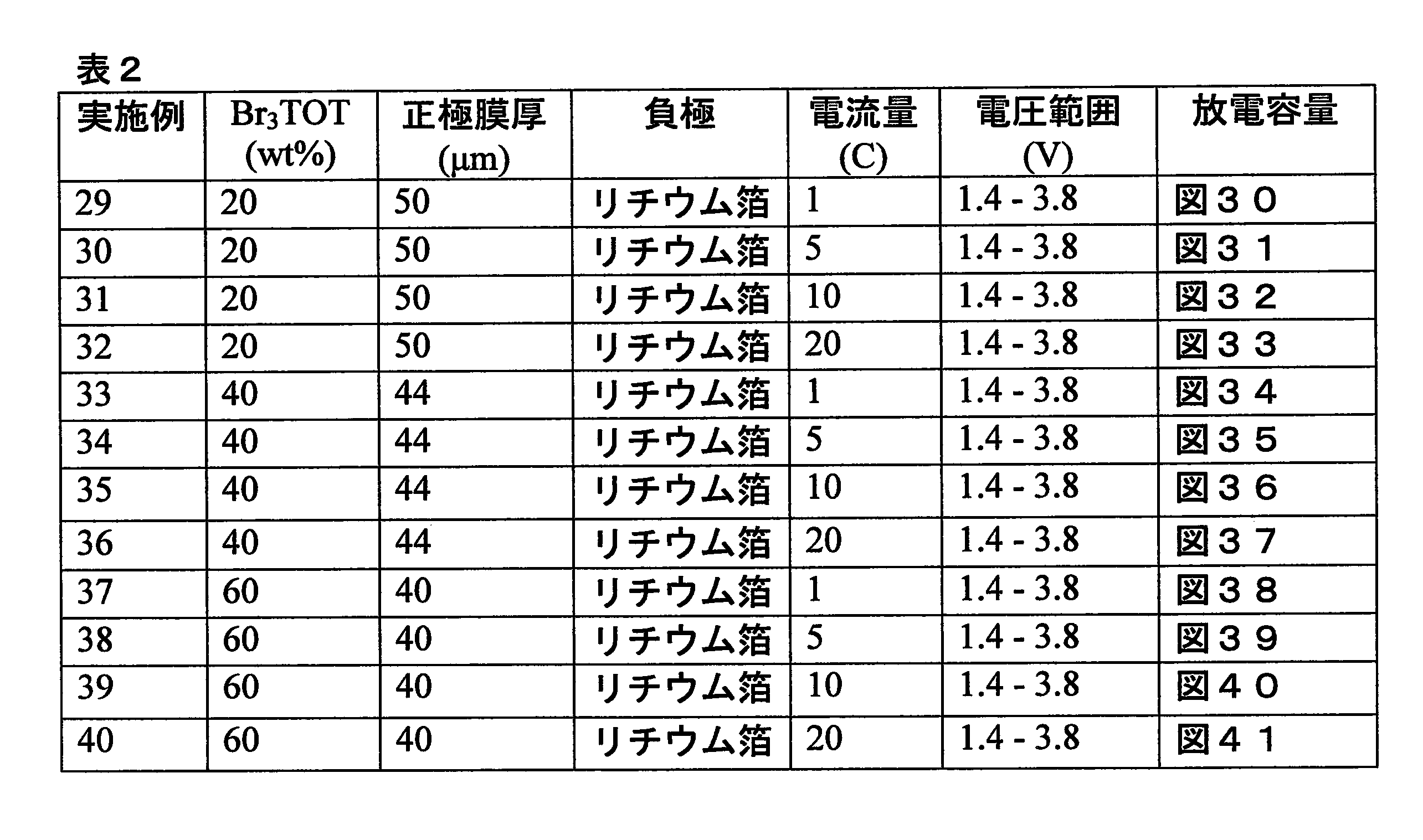
<実施例41~実施例47(H3TOTリチウムイオン二次電池の製造)>
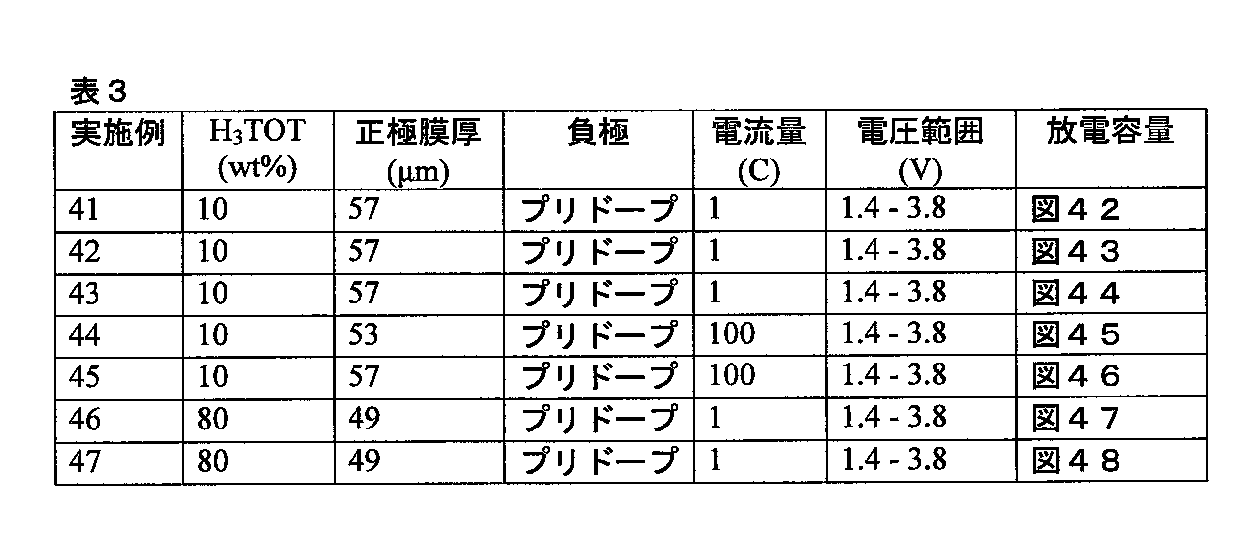
H3TOTを用いて実施例1と同様に正極シートを作製し、プリドープ負極と組合せてリチウムイオン二次電池を製造した。この際、電解質として実施例43、45および47では2.0MのLiPF6を用い、他は1.0MのLiPF6を用いた。また電解液溶媒として実施例41、46および47ではエチレンカーボネート/ジエチルカーボネート(体積比1:1)、実施例43および45ではエチレンカーボネート/ジエチルカーボネート(体積比3:7)、実施例42および44ではエチレンカーボネート/ジメチルカーボネート(体積比3:7)を使用した。充放電評価は実施例41~43、46および47は東洋システムズ(株)製充放電試験機TOSCAT-3100を使用し、実施例44および45は同TOSCAT-3300を使用した。作製条件および充放電条件の詳細を表3に、放電特性を図42~図48に示す。
H3TOTを用いて実施例1と同様に正極シートを作製し、プリドープ負極と組合せてリチウムイオン二次電池を製造した。この際、電解質として実施例43、45および47では2.0MのLiPF6を用い、他は1.0MのLiPF6を用いた。また電解液溶媒として実施例41、46および47ではエチレンカーボネート/ジエチルカーボネート(体積比1:1)、実施例43および45ではエチレンカーボネート/ジエチルカーボネート(体積比3:7)、実施例42および44ではエチレンカーボネート/ジメチルカーボネート(体積比3:7)を使用した。充放電評価は実施例41~43、46および47は東洋システムズ(株)製充放電試験機TOSCAT-3100を使用し、実施例44および45は同TOSCAT-3300を使用した。作製条件および充放電条件の詳細を表3に、放電特性を図42~図48に示す。
H3TOT 10wt%で充放電速度1Cの系では、図42~図44と比較して電解質および電解液の違いはあまり影響がないと言える。100Cの場合も同様である(図45と図46)。H3TOT 80wt%の系(図47と図48)では電解質濃度を比較したが、大きな差は認められない。
Claims (12)
- 下記式(1)で示されるトリオキソトリアンギュレン誘導体と、カーボンナノチューブとを含む、非水電解質二次電池に用いる電極シート。

- 前記Xは、水素、ハロゲン、炭素数6以下のアルキル基もしくはアリール基、またはこれらの組み合わせである、請求項1に記載の電極シート。
- 前記ハロゲンが臭素(X=Br)である、請求項2に記載の電極シート。
- 前記トリオキソトリアンギュレン誘導体が無置換体(X=H)である、請求項1または請求項2に記載の電極シート。
- 前記カーボンナノチューブが多層カーボンナノチューブである、請求項1から請求項4のいずれか1項に記載の電極シート。
- 前記カーボンナノチューブが層状に積層され、各層ごとに前記トリオキソトリアンギュレン誘導体が分散されている、請求項1から請求項5のいずれか1項に記載の電極シート。
- バインダーを含まない、請求項1から請求項6のいずれか1項に記載の電極シート。
- 下記式(1)で示されるトリオキソトリアンギュレン誘導体と、カーボンナノチューブとを溶媒に分散させた後、当該分散液を2回以上濾過し、濾過後の残渣を乾燥させて、2以上の層からなる電極シートとする、非水電解質二次電池に用いる電極シートの製造方法。
- 請求項1から請求項7に記載の電極シートを備えた非水電解質二次電池。
- 前記電極シートを正極として用いた、請求項9に記載の非水電解質二次電池。
- 前記非水電解質二次電池がリチウムイオン二次電池である、請求項9に記載の非水電解質二次電池。
- 前記電極シートを正極として用い、負極がグラファイトにあらかじめリチウムを挿入させたプリドープ負極である、請求項11に記載の非水電解質二次電池。
Priority Applications (2)
| Application Number | Priority Date | Filing Date | Title |
|---|---|---|---|
| JP2017528394A JP6846745B2 (ja) | 2015-07-13 | 2016-07-04 | 非水電解質二次電池に用いる電極シートおよび非水電解質二次電池 |
| US15/870,232 US10826056B2 (en) | 2015-07-13 | 2018-01-12 | Electrode sheet used in nonaqueous electrolyte secondary battery and nonaqueous electrolyte secondary battery |
Applications Claiming Priority (2)
| Application Number | Priority Date | Filing Date | Title |
|---|---|---|---|
| JP2015139965 | 2015-07-13 | ||
| JP2015-139965 | 2015-07-13 |
Related Child Applications (1)
| Application Number | Title | Priority Date | Filing Date |
|---|---|---|---|
| US15/870,232 Continuation US10826056B2 (en) | 2015-07-13 | 2018-01-12 | Electrode sheet used in nonaqueous electrolyte secondary battery and nonaqueous electrolyte secondary battery |
Publications (1)
| Publication Number | Publication Date |
|---|---|
| WO2017010334A1 true WO2017010334A1 (ja) | 2017-01-19 |
Family
ID=57757763
Family Applications (1)
| Application Number | Title | Priority Date | Filing Date |
|---|---|---|---|
| PCT/JP2016/069811 Ceased WO2017010334A1 (ja) | 2015-07-13 | 2016-07-04 | 非水電解質二次電池に用いる電極シートおよび非水電解質二次電池 |
Country Status (3)
| Country | Link |
|---|---|
| US (1) | US10826056B2 (ja) |
| JP (1) | JP6846745B2 (ja) |
| WO (1) | WO2017010334A1 (ja) |
Cited By (2)
| Publication number | Priority date | Publication date | Assignee | Title |
|---|---|---|---|---|
| JP2019067625A (ja) * | 2017-09-29 | 2019-04-25 | トヨタ自動車株式会社 | 二次電池 |
| JP2019175681A (ja) * | 2018-03-28 | 2019-10-10 | 株式会社カネカ | 非水電解質二次電池の正極、非水電解質二次電池およびその製造方法 |
Citations (8)
| Publication number | Priority date | Publication date | Assignee | Title |
|---|---|---|---|---|
| JPH07235330A (ja) * | 1994-02-24 | 1995-09-05 | Sony Corp | 非水電解液二次電池の製造方法 |
| JPH1167207A (ja) * | 1997-08-12 | 1999-03-09 | Toyota Central Res & Dev Lab Inc | リチウム二次電池用負極 |
| JP2007227186A (ja) * | 2006-02-24 | 2007-09-06 | Osaka Univ | 分子結晶性二次電池 |
| EP2037516A1 (en) * | 2007-09-14 | 2009-03-18 | Hong Fu Jin Precision Industry (ShenZhen) Co. Ltd. | Lithium battery and method for fabricating anode thereof |
| JP2010251442A (ja) * | 2009-04-14 | 2010-11-04 | Toyota Motor Corp | 蓄電デバイス用電極の製造方法 |
| WO2013042706A1 (ja) * | 2011-09-20 | 2013-03-28 | 公立大学法人大阪市立大学 | 有機分子スピンバッテリー |
| WO2014077252A1 (ja) * | 2012-11-13 | 2014-05-22 | 保土谷化学工業株式会社 | 多層カーボンナノチューブの水分散液 |
| JP2014107191A (ja) * | 2012-11-29 | 2014-06-09 | Mikuni Color Ltd | カーボンナノチューブを用いた分散スラリー及びリチウムイオン二次電池 |
Family Cites Families (6)
| Publication number | Priority date | Publication date | Assignee | Title |
|---|---|---|---|---|
| JP4632020B2 (ja) | 2004-01-23 | 2011-02-16 | 日本電気株式会社 | 非水電解液二次電池 |
| CN101409338A (zh) | 2007-10-10 | 2009-04-15 | 清华大学 | 锂离子电池负极,其制备方法和应用该负极的锂离子电池 |
| CN101388447B (zh) | 2007-09-14 | 2011-08-24 | 清华大学 | 锂离子电池负极及其制备方法 |
| CN101409337B (zh) | 2007-10-10 | 2011-07-27 | 清华大学 | 锂离子电池负极,其制备方法和应用该负极的锂离子电池 |
| JP2009295881A (ja) | 2008-06-06 | 2009-12-17 | Kaneka Corp | エネルギー貯蔵デバイス |
| US20140332731A1 (en) * | 2012-04-02 | 2014-11-13 | CNano Technology Limited | Electrode Composition for Battery |
-
2016
- 2016-07-04 JP JP2017528394A patent/JP6846745B2/ja active Active
- 2016-07-04 WO PCT/JP2016/069811 patent/WO2017010334A1/ja not_active Ceased
-
2018
- 2018-01-12 US US15/870,232 patent/US10826056B2/en not_active Expired - Fee Related
Patent Citations (8)
| Publication number | Priority date | Publication date | Assignee | Title |
|---|---|---|---|---|
| JPH07235330A (ja) * | 1994-02-24 | 1995-09-05 | Sony Corp | 非水電解液二次電池の製造方法 |
| JPH1167207A (ja) * | 1997-08-12 | 1999-03-09 | Toyota Central Res & Dev Lab Inc | リチウム二次電池用負極 |
| JP2007227186A (ja) * | 2006-02-24 | 2007-09-06 | Osaka Univ | 分子結晶性二次電池 |
| EP2037516A1 (en) * | 2007-09-14 | 2009-03-18 | Hong Fu Jin Precision Industry (ShenZhen) Co. Ltd. | Lithium battery and method for fabricating anode thereof |
| JP2010251442A (ja) * | 2009-04-14 | 2010-11-04 | Toyota Motor Corp | 蓄電デバイス用電極の製造方法 |
| WO2013042706A1 (ja) * | 2011-09-20 | 2013-03-28 | 公立大学法人大阪市立大学 | 有機分子スピンバッテリー |
| WO2014077252A1 (ja) * | 2012-11-13 | 2014-05-22 | 保土谷化学工業株式会社 | 多層カーボンナノチューブの水分散液 |
| JP2014107191A (ja) * | 2012-11-29 | 2014-06-09 | Mikuni Color Ltd | カーボンナノチューブを用いた分散スラリー及びリチウムイオン二次電池 |
Cited By (3)
| Publication number | Priority date | Publication date | Assignee | Title |
|---|---|---|---|---|
| JP2019067625A (ja) * | 2017-09-29 | 2019-04-25 | トヨタ自動車株式会社 | 二次電池 |
| JP2019175681A (ja) * | 2018-03-28 | 2019-10-10 | 株式会社カネカ | 非水電解質二次電池の正極、非水電解質二次電池およびその製造方法 |
| JP7090259B2 (ja) | 2018-03-28 | 2022-06-24 | 株式会社カネカ | 非水電解質二次電池の正極、非水電解質二次電池およびその製造方法 |
Also Published As
| Publication number | Publication date |
|---|---|
| US10826056B2 (en) | 2020-11-03 |
| US20180138499A1 (en) | 2018-05-17 |
| JP6846745B2 (ja) | 2021-03-24 |
| JPWO2017010334A1 (ja) | 2018-04-26 |
Similar Documents
| Publication | Publication Date | Title |
|---|---|---|
| Gu et al. | Local protonation of polyaniline induced by nitrogen-doped carbon skeleton towards ultra-stable Zn-organic batteries with a dual-ion insertion/extraction mechanism | |
| Zeng et al. | Nonflammable fluorinated carbonate electrolyte with high salt-to-solvent ratios enables stable silicon-based anode for next-generation lithium-ion batteries | |
| Li et al. | Novel approach toward a binder-free and current collector-free anode configuration: highly flexible nanoporous carbon nanotube electrodes with strong mechanical strength harvesting improved lithium storage | |
| Deyab et al. | PANI@ Co-Porphyrins composite for the construction of supercapacitors | |
| Fu et al. | A facile route to controllable synthesis of Fe3O4/graphene composites and their application in lithium-ion batteries | |
| Yi et al. | A light-weight free-standing graphene foam-based interlayer towards improved Li-S cells | |
| TWI624104B (zh) | 鋰離子二次電池 | |
| Tian et al. | Phytic acid modified manganese dioxide/graphene composite aerogel as high-performance electrode materials for supercapacitors | |
| Wang et al. | Three‐dimensional interconnected network of graphene‐wrapped silicon/carbon nanofiber hybrids for binder‐free anodes in lithium‐ion batteries | |
| JP2013539193A (ja) | 充電式リチウム−硫黄電池電極用のグラフェン−硫黄ナノ複合体 | |
| Feng et al. | Nano-silicon/polyaniline composites with an enhanced reversible capacity as anode materials for lithium ion batteries | |
| Ahmad et al. | A graphene supported polyimide nanocomposite as a high performance organic cathode material for lithium ion batteries | |
| CN108475585B (zh) | 非水系锂蓄电元件 | |
| Tang et al. | Organics‐MXene composites as electrode materials for energy storage | |
| JP2013054958A (ja) | 非水電解質二次電池用負極材、リチウムイオン二次電池及び電気化学キャパシタ | |
| Yang et al. | Li3V2 (PO4) 3/C composite materials synthesized using the hydrothermal method with double-carbon sources | |
| Deng et al. | Strongly coupled perylene bisimide/reduced graphene oxide as organic cathode materials for lithium ion batteries | |
| Kim et al. | Prominent enhancement of stability under high current density of LiFePO4-based multidimensional nanocarbon composite as cathode for lithium-ion batteries | |
| JP2017204364A (ja) | アルカリ金属含有アモルファスカーボン活物質の製造方法およびそれを用いた電極の製造方法 | |
| Shen et al. | Versatile MnO2/CNT Putty‐Like Composites for High‐Rate Lithium‐Ion Batteries | |
| Ershadi et al. | Preparing graphene-based anodes with enhanced electrochemical performance for lithium-ion batteries | |
| Ventrapragada et al. | A versatile carbon nanotube-based scalable approach for improving interfaces in Li-ion battery electrodes | |
| Kim et al. | Conductive Agent‐Controlled Tortuosity in Solvent‐Free Thick‐Film Electrodes for High‐Energy Lithium‐Ion Batteries | |
| Qian et al. | Sb particles embedded in N-doped carbon spheres wrapped by graphene for superior K+− Storing performances | |
| Chakrabarti et al. | Scaling to practical pouch cell supercapacitor: electrodes by electrophoretic deposition |
Legal Events
| Date | Code | Title | Description |
|---|---|---|---|
| 121 | Ep: the epo has been informed by wipo that ep was designated in this application |
Ref document number: 16824314 Country of ref document: EP Kind code of ref document: A1 |
|
| ENP | Entry into the national phase |
Ref document number: 2017528394 Country of ref document: JP Kind code of ref document: A |
|
| NENP | Non-entry into the national phase |
Ref country code: DE |
|
| 122 | Ep: pct application non-entry in european phase |
Ref document number: 16824314 Country of ref document: EP Kind code of ref document: A1 |