WO2017010184A1 - 多孔質セラミック粒子 - Google Patents
多孔質セラミック粒子 Download PDFInfo
- Publication number
- WO2017010184A1 WO2017010184A1 PCT/JP2016/066504 JP2016066504W WO2017010184A1 WO 2017010184 A1 WO2017010184 A1 WO 2017010184A1 JP 2016066504 W JP2016066504 W JP 2016066504W WO 2017010184 A1 WO2017010184 A1 WO 2017010184A1
- Authority
- WO
- WIPO (PCT)
- Prior art keywords
- porous ceramic
- ceramic particles
- particles
- adhesive
- bulk body
- Prior art date
- Legal status (The legal status is an assumption and is not a legal conclusion. Google has not performed a legal analysis and makes no representation as to the accuracy of the status listed.)
- Ceased
Links
Images



Classifications
-
- C—CHEMISTRY; METALLURGY
- C01—INORGANIC CHEMISTRY
- C01G—COMPOUNDS CONTAINING METALS NOT COVERED BY SUBCLASSES C01D OR C01F
- C01G25/00—Compounds of zirconium
- C01G25/02—Oxides
-
- C—CHEMISTRY; METALLURGY
- C04—CEMENTS; CONCRETE; ARTIFICIAL STONE; CERAMICS; REFRACTORIES
- C04B—LIME, MAGNESIA; SLAG; CEMENTS; COMPOSITIONS THEREOF, e.g. MORTARS, CONCRETE OR LIKE BUILDING MATERIALS; ARTIFICIAL STONE; CERAMICS; REFRACTORIES; TREATMENT OF NATURAL STONE
- C04B38/00—Porous mortars, concrete, artificial stone or ceramic ware; Preparation thereof
-
- C—CHEMISTRY; METALLURGY
- C04—CEMENTS; CONCRETE; ARTIFICIAL STONE; CERAMICS; REFRACTORIES
- C04B—LIME, MAGNESIA; SLAG; CEMENTS; COMPOSITIONS THEREOF, e.g. MORTARS, CONCRETE OR LIKE BUILDING MATERIALS; ARTIFICIAL STONE; CERAMICS; REFRACTORIES; TREATMENT OF NATURAL STONE
- C04B2201/00—Mortars, concrete or artificial stone characterised by specific physical values
- C04B2201/30—Mortars, concrete or artificial stone characterised by specific physical values for heat transfer properties such as thermal insulation values, e.g. R-values
- C04B2201/32—Mortars, concrete or artificial stone characterised by specific physical values for heat transfer properties such as thermal insulation values, e.g. R-values for the thermal conductivity, e.g. K-factors
Definitions
- the present invention relates to a porous ceramic particle, and more particularly to a porous ceramic particle suitable for reducing the thermal conductivity of a constituent member containing the porous ceramic particle.
- Examples of the filler filled in the heat insulating material and the film include compositions and hollow particles described in JP2010-155946A, JP2004-10903A, and JP2010-64945A.
- JP 2010-155946 describes a curable organopolysiloxane composition capable of forming a cured porous organopolysiloxane having a low thermal conductivity.
- Japanese Patent Application Laid-Open No. 2004-10903 describes that a film having low thermal conductivity is formed using a paint using hollow particles having low thermal conductivity.
- nanoparticle-coated composite particles are produced by adsorbing additive particles on the surface of the base material particles by electrostatic interaction, and further, using this, a normal powder metallurgy process is performed. It is described that a composite material is manufactured via.
- the techniques described in Japanese Patent Application Laid-Open Nos. 2010-155946 and 2004-10903 have been insufficient in reducing the thermal conductivity.
- the technique described in Japanese Patent Application Laid-Open No. 2010-64945 is intended to produce a composite material by powder metallurgy, and therefore it is intended to coat the base material particles with fine particles having a particle size of the order of nm. For this reason, the distance between the base material particles is shortened, and pores are hardly formed when sintered, and even if formed, the amount is small, so that in this case too, low thermal conductivity is insufficient.
- the particles added to the adhesive are small, it is difficult to uniformly disperse the particles in the adhesive. Moreover, since it is necessary to set it on a base material (target object to which a bulk body is stuck) after baking the adhesive agent with which particle
- the present invention has been made in consideration of such problems, and can achieve low thermal conductivity, and can be directly installed on an object using an adhesive, etc. It is an object to provide porous ceramic particles that can be facilitated.
- the porous ceramic particles according to the present invention are porous ceramic particles having a porosity of 20 to 99%, wherein one main surface is a mirror surface and an aspect ratio is 3 or more. .
- the other principal surface facing the one principal surface may be a mirror surface.
- the present invention it is preferable to have a plurality of side surfaces, and the side surfaces are rough surfaces.
- the minimum length of the outer shape is preferably 50 to 500 ⁇ m.
- the average pore diameter is preferably 500 nm or less.
- the thermal conductivity is preferably 1 W / mK or less.
- the fine particles have a three-dimensional structure, and the particle diameter of the fine particles is 1 nm to 5 ⁇ m.
- the interparticle distance is preferably 10 ⁇ m or less.
- porous ceramic particles according to the present invention may be disposed on a sheet.
- porous ceramic particles according to the present invention it is possible to reduce the thermal conductivity, and it can be installed directly on an object using an adhesive or the like, thereby facilitating the installation of the bulk body. it can.
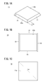
- FIG. 1A is a perspective view showing an example in which the porous ceramic particles according to the present embodiment are arranged with one main surface facing downward, and FIG. 1B shows the porous ceramic particles shown in FIG. 1A from above.
- FIG. 1C is a bottom view showing the porous ceramic particles shown in FIG. 1A as viewed from below.
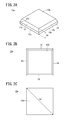
- FIG. 2A is a perspective view showing an example in which the porous ceramic particles according to the modified example are arranged with one main surface facing downward, and FIG. 2B shows the porous ceramic particles shown in FIG. 2A as viewed from above.
- FIG. 2C is a bottom view showing the porous ceramic particles shown in FIG. 2A as viewed from below.
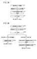
- FIG. 3A is a flowchart showing one example of a method for producing porous ceramic particles, and FIG.
- FIG. 3B is a flowchart showing another example of a method for producing porous ceramic particles.
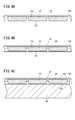
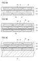
- FIG. 4A is a process diagram showing a state in which a plurality of porous ceramic particles and a slurry containing an adhesive component are poured into a mold (not shown), and FIG. 4B is a diagram showing a bulk body after drying and baking and solidifying the slurry.
- FIG. 4C is a process diagram illustrating a state in which a bulk body is installed on a base material (an object to which the bulk body is attached).
- FIG. 5A is an explanatory diagram illustrating a state in which a plurality of particles are dispersed in a slurry in the conventional example, with a part omitted, and FIG.
- FIG. 5B illustrates a state in which the slurry is solidified to form a bulk body.
- FIG. 6A is a process diagram showing a state in which a plurality of porous ceramic particles (a plurality of particle aggregates) and a slurry containing an adhesive component are poured into a mold (not shown), and
- FIG. 6C is a process diagram showing a state in which the bulk body is set on an object.
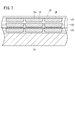
- FIG. 7 is a cross-sectional view showing a part of an example in which a plurality of porous ceramic particles are aligned in the longitudinal direction in a bulk body.
- FIG. 8A is a cross-sectional view showing one example in which a dense layer is disposed on porous ceramic particles, and FIG.
- FIG. 8B is a partial illustration of another example in which a dense layer is disposed on porous ceramic particles. It is sectional drawing shown.
- FIG. 9A is a process diagram illustrating a state in which an adhesive is applied on an object
- FIG. 9B illustrates a plurality of sheets on an adhesive using a sheet in which a plurality of porous ceramic particles are attached to one surface. It is process drawing which shows the state which transcribe
- FIG. 9C is process drawing which shows the state which peeled the sheet
- 10A is a cross-sectional view showing a part of an example in which a bulk body is formed by applying an adhesive on a plurality of porous ceramic particles
- FIG. 10B is an upper layer adhesive from the state of FIG. 10A.
- FIG. 10C is a cross-sectional view showing an example in which a plurality of porous ceramic particles are further transferred and a bulk body is partially omitted
- FIG. 10C is a diagram illustrating the state of FIG. 10B on the plurality of porous ceramic particles. It is sectional drawing which abbreviate
- porous ceramic particles according to the present invention will be described with reference to FIGS. 1A to 10C.
- “to” indicating a numerical range is used as a meaning including numerical values described before and after the numerical value as a lower limit value and an upper limit value.
- the porous ceramic particle 10 includes one main surface 12a, another main surface 12b facing the one main surface 12a, and a plurality of side surfaces 14 (for example, It has a three-dimensional shape having four side surfaces 14), and examples thereof include a polygonal shape and a disk shape.
- FIG. 1A shows an example in which the outer shape of the porous ceramic particles 10 is a quadrangular pyramid shape, and one main surface 12a is disposed downward and the other main surface 12b is disposed upward.
- the one main surface 12a and the other main surface 12b may face each other in front of each other, or may face each other at an angle.
- the inclination angle ⁇ of each side surface 14 may be the same or different.
- the inclination angle ⁇ of at least one side surface 14 may be different from the inclination angle ⁇ of the other side surface 14.
- the inclination angle ⁇ of the side surface 14 refers to an inclination angle with respect to the one principal surface 12a.
- each side surface 14 may be composed of a plurality of surfaces 14a and 14b having different inclination angles ⁇ a and ⁇ b, respectively, like the porous ceramic particle 10a according to the modification shown in FIG. 2A.
- the shape viewed from the top may be a rectangular shape as shown in FIGS. 1A and 2A, or other polygonal shapes such as pentagonal shape, hexagonal shape, octagonal shape, etc. Alternatively, it may be a track shape, an oval shape, a circular shape, or the like.
- each ridgeline part of the external shape may be a curved surface (R surface).
- At least one main surface 12a of the porous ceramic particles 10, 10a is a mirror surface.
- the mirror surface refers to a surface having a surface roughness Ra of 1 ⁇ m or less.
- One main surface 12a which is a mirror surface is preferably smaller in surface roughness Ra than the other main surface 12b facing each other.
- the opposing other main surface 12b preferably has a large surface roughness Ra.
- the other main surface 12b facing the one main surface 12a is also preferably a mirror surface.
- the surface roughness Ra of the one main surface is less than 90% of the surface roughness Ra of the other main surface.
- the side surfaces 14 of the porous ceramic particles 10 and 10a are preferably rough surfaces.
- the rough surface is a surface having a surface roughness Ra exceeding 1 ⁇ m, preferably a surface having a surface roughness Ra of 5 ⁇ m or more and 10 ⁇ m or less.
- the porous ceramic particles 10 and 10a preferably have an aspect ratio of 3 or more. More preferably, it is 5 or more, more preferably 7 or more.
- the aspect ratio refers to the maximum length La / minimum length Lb as shown in FIGS. 1A, 1C, 2A, and 2C, for example.
- the maximum length La is the maximum length of the widest surface (here, one main surface 12a) among the plurality of surfaces constituting the porous ceramic particles 10 and 10a.
- the minimum length Lb refers to the thickness of the thinnest portion of the thickness of the porous ceramic particles 10 and 10a as shown in FIGS. 1A and 2A.
- the minimum length Lb is preferably 50 to 500 ⁇ m, more preferably 55 to 400 ⁇ m, more preferably 60 to 300 ⁇ m, and particularly preferably 70 to 200 ⁇ m.
- porous means a state that is neither dense nor hollow, and means a state composed of a plurality of pores or particles.
- the term “dense” refers to a state in which a plurality of fine particles are combined without gaps and does not have pores.
- the hollow means a state in which the inside is hollow and the outer shell portion is dense.
- the porosity of the porous ceramic particles 10 and 10a is 20 to 99%, and the pore is at least one of closed pores and open pores, and may include both. Further, the shape of the pores, that is, the surface shape of the opening may be any shape such as a square, a quadrangle, a triangle, a hexagon, and a circle.
- the average pore diameter is preferably 500 nm or less, more preferably 10 to 500 nm. This dimension is effective in inhibiting the generation of lattice vibration (phonon), which is the main cause of heat conduction.
- the porous ceramic particles 10 and 10a have a structure in which fine particles are three-dimensionally connected.
- the particle diameter of the fine particles is preferably 1 nm to 5 ⁇ m. More preferably, it is 50 nm to 1 ⁇ m.
- the porous ceramic particles 10 and 10a composed of fine particles having a particle diameter in such a range are effective in achieving low thermal conductivity because generation of lattice vibration (phonon), which is a main cause of heat conduction, is hindered.
- the fine particles may be particles (single crystal particles) made of one crystal grain or particles (polycrystalline particles) made of a large number of crystal grains. That is, the porous ceramic particles 10 and 10a are preferably a collection of fine particles having a particle diameter in this range.
- the particle size of the fine particles is the size of one fine particle (the diameter if spherical, the maximum diameter otherwise) of the particles constituting the skeleton of the porous ceramic particles 10 and 10a. It was measured from the image.
- the thermal conductivity of the porous ceramic particles 10 and 10a is preferably 1 W / mK or less, more preferably 0.7 W / mK or less, more preferably 0.5 W / mK or less, particularly preferably 0.3 W / mK. It is as follows.
- the constituent material of the porous ceramic particles 10 and 10a preferably includes a metal oxide, and more preferably includes only a metal oxide. This is because when the metal oxide is included, the thermal conductivity tends to be low because the ionic bond between the metal and oxygen is stronger than the metal non-oxide (for example, carbide or nitride).
- the metal non-oxide for example, carbide or nitride
- the metal oxide is an oxide of one element selected from the group consisting of Zr, Y, Al, Si, Ti, Nb, Sr, La, Hf, Ce, Gd, Sm, Mn, Yb, Er, and Ta, or 2
- a composite oxide of the above elements is preferable. This is because when the metal oxide is an oxide or composite oxide of these elements, heat conduction due to lattice vibration (phonon) is less likely to occur.
- ZrO 2 —HfO 2 —Y 2 O 3 ZrO 2 —Y 2 O 3 —La 2 O 3
- ZrO 2 —HfO 2 —Y 2 O 3 La 2 O 3
- HfO 2 —Y 2 O 3 CeO 2 —Y 2 O 3
- Gd 2 Zr 2 O 7 Sm 2 Zr 2 O 7
- LaMnAl 11 O 19 YTa 3 O 9
- Y 0.7 La 0.3 Ta 3 O 9 Y 1.08 Ta 2.76
- Zr Examples include 0.24 O 9 , Y 2 Ti 2 O 7 , LaTa 3 O 9 , Yb 2 Si 2 O 7 , Y 2 Si 2 O 7 , Ti 3 O 5 and the like.
- step S1 of FIG. 3A a pore forming material, a binder, a plasticizer, and a solvent are added to and mixed with the powder of the constituent material of the porous ceramic particles 10 and 10a described above to prepare a molding slurry.
- step S2 after the viscosity is adjusted by subjecting the slurry to vacuum defoaming, a molded body (green sheet) is produced so that the thickness after firing becomes the minimum length by, for example, a doctor blade device. To do.
- step S3 the green body is fired to obtain a sheet-like sintered body.
- step S4 the sintered body is processed with a laser to obtain porous ceramic particles 10 and 10a according to the present embodiment.
- the sintered body may be separated into a plurality of porous ceramic particles by passing laser light through the sintered body.
- porous ceramic particles 10 as shown in FIGS. 1A to 1C are obtained.
- the sintered body may be separated into a plurality of porous ceramic particles by causing the laser beam to reach the middle of the sintered body in the thickness direction and then bending the sintered body.
- porous ceramic particles 10a according to the modification shown in FIGS. 2A to 2C are obtained.
- steps S101 and S102 after the molding slurry is prepared, the thickness after firing becomes the minimum length in the same manner as in steps S1 and S2 of FIG. 3A. Thus, a molded body (green sheet) is prepared.
- step S103 the molded body (green sheet) is processed with a laser to produce a plurality of porous ceramic particle precursors or a molded body having a plurality of irregularities (green sheet).
- step S104a a plurality of porous ceramic particle precursors are fired to obtain a plurality of porous ceramic particles 10 as shown in FIGS. 1A to 1C, for example.
- step S104b a sintered body having a plurality of irregularities is obtained by firing a molded body having a plurality of irregularities.
- step S105 the sintered body having a plurality of irregularities is separated into a plurality of porous ceramic particles 10a.
- a plurality of porous ceramic particles 10 and a slurry 22 containing an adhesive component are poured into a mold (not shown). At this time, the plurality of porous ceramic particles 10 can be uniformly dispersed in the slurry 22. Thereafter, as shown in FIG. 4B, the slurry 22 is dried, fired and solidified to produce the bulk body 20. In the bulk body 20, a plurality of porous ceramic particles 10 are uniformly dispersed in the adhesive 24. Thereafter, as shown in FIG. 4C, the bulk body 20 is placed on the object 26 via an adhesive or the like. At this time, for example, the bulk body 20 is installed so that the other principal surface 12 b of each porous ceramic particle 10 faces the object 26.
- each porous ceramic particle 10 is a mirror surface, for example, there is almost no thickness unevenness in the slurry 22 interposed on the particle assembly 100.
- the plurality of porous ceramic particles 10 constituting the particle assembly 100 can also be dispersed in a layered manner and uniformly.
- a porous ceramic particle aggregate 100 two or more layers of a plurality of porous ceramic particles 10 dispersed in layers, that is, a porous ceramic particle aggregate (hereinafter simply referred to as a particle aggregate 100). Even in this case, the following effects are exhibited. That is, since one main surface 12a of each porous ceramic particle 10 is a mirror surface, for example, there is almost no thickness unevenness in the slurry 22 interposed on the particle assembly 100 of the first layer. Therefore, the plurality of porous ceramic particles 10 constituting the second-layer particle assembly 100 arranged on the first-layer particle assembly 100 can also be dispersed in a layered manner. The same applies to the particle aggregate 100 in the third layer or more.
- each porous ceramic particle 10 is a rough surface
- the upper layer slurry 22 is less likely to go into the lower layer of the porous ceramic particle 10.
- the lower layer slurry 22 is made of porous ceramic particles. It becomes difficult to wrap around the upper layer of 10.
- the distance between the particle aggregates 100 can be made substantially constant, and the distance between the porous ceramic particles 10 constituting the particle aggregate 100 can also be made almost constant. That is, the distance between the porous ceramic particles 10 (interparticle distance) can be regulated to 10 ⁇ m or less.
- the phenomenon that the thickness of the adhesive 24 in the lower layer of the first particle aggregate 100 becomes extremely thick can be avoided.
- the distance between particles is preferably 7 ⁇ m or less, and more preferably 4 ⁇ m or less. However, the distance between particles is not necessarily small, and 0.1 ⁇ m or more is necessary. If there is an inter-particle distance of 0.1 ⁇ m or more, the following effects are exhibited when the bulk body 20 is adhered to the object 26 and used after the bulk body 20 is formed by subsequent film formation. That is, when the surface side of the bulk body 20 becomes high temperature and the object 26 side becomes low temperature, the bulk body 20 itself undergoes thermal expansion, but there is an interparticle distance (gap) of 0.1 ⁇ m or more. It becomes easy to relieve the thermal stress generated in the porous ceramic particles 10, the adhesive 24, the object 26, and the like.
- the plurality of porous ceramic particles 10 can be uniformly dispersed in the slurry 22, there is only a region of the adhesive 24 having a higher thermal conductivity than the porous ceramic particles 10. It becomes narrow and can suppress the thermal conductivity of the bulk body 20 low.
- the thermal conductivity between the bulk bodies 20 can be made uniform, and there is no need to change the bulk body 20 according to the location where the bulk body 20 is placed, simplifying the placement process and reducing the number of steps. Can be achieved.
- FIG. 6A to 6C show an example in which a plurality of porous ceramic particles 10 are arranged in a staggered arrangement, but a plurality of porous ceramic particles 10 may be aligned in the vertical direction as shown in FIG. .
- FIG. 7 since the region of only the adhesive 24 is connected in the vertical direction, the effect of suppressing the thermal conductivity lower than in the case of the staggered arrangement may be reduced.
- a dense layer 32 may be disposed on one main surface 12 a of the porous ceramic particles 10.
- the strength of each porous ceramic particle 10 can be improved.
- the dense layer 32 may be disposed on both the one main surface 12a and the other main surface 12b of the porous ceramic particle 10.
- the adhesive 24 can be prevented from soaking into the porous ceramic particle 10, and the strength of the porous ceramic particle 10 can be increased. Can do.
- the dense layer 32 may be disposed on the porous ceramic particle 10 by disposing the separate dense layer 32 on the porous ceramic particle 10 or by forming an altered layer (dense layer) on the porous ceramic particle 10 itself. May be.
- an adhesive 24 is applied on the object 26.
- the plurality of porous ceramic particles 10 are transferred onto the adhesive 24 of the object 26 using, for example, a sheet 34 having a plurality of porous ceramic particles 10 attached to one surface.
- the inter-particle distance between the plurality of porous ceramic particles 10 attached to the sheet 34 is set to 10 ⁇ m or less.
- the distance between particles is preferably 7 ⁇ m or less, and more preferably 4 ⁇ m or less.
- the sheet 34 is an adhesive sheet or film and is preferably capable of being peeled off by an external factor such as heat or electricity.
- the bulk body 20 made of the plurality of porous ceramic particles 10 and the adhesive 24 is placed on the object 26. That is, the bulk body 20 made of the single-layer particle aggregate 100 and the adhesive 24 is installed.
- the bulk body 20 may be configured by applying an adhesive 24 on the plurality of porous ceramic particles 10.
- the adhesive 24 since the outer surface of the porous ceramic particle 10 is covered with the adhesive 24, the strength becomes stronger, but the thermal conductivity may be higher than that in the example of FIG. 9C.
- a plurality of porous ceramic particles 10 may be further transferred onto the upper layer adhesive 24 from the state shown in FIG. 10A to constitute the bulk body 20. That is, the bulk body 20 is configured by the two-layer particle assembly 100 and the adhesive 24. Further, as shown in FIG. 10C, the bulk body 20 may be configured by applying an adhesive 24 on the plurality of porous ceramic particles 10 from the state of FIG. 10B.
- a plurality of porous ceramic particles 10 can be uniformly dispersed in the adhesive 24 as in the first method. And since the area
- a plurality of porous ceramic particles 10 are arranged on the object 26 via the adhesive 24 without using the bulk body 20 in advance, and the adhesive 24 is formed thereon. Therefore, the plurality of porous ceramic particles 10 can be uniformly arranged on the object 26.
- the adhesive strength (JIS Z0237) of the sheet 34 is preferably 1.0 N / 10 mm or more, the tensile elongation (JIS K7127) is 0.5% or more, and the thickness is preferably 5 mm or less. Thereby, the following effects can be produced.
- C The smaller the thickness, the easier it is to follow the curved surface.
- the adhesive strength of the sheet 34 is as follows. That is, the adhesive strength when holding the porous ceramic particles 10 is 1.0 N / 10 mm or more, and the adhesive strength when peeling the porous ceramic particles 10 is 0.1 N / 10 mm or less.
- the method for evaluating the adhesive strength of the sheet 34 is the same as the method for evaluating the adhesive strength of the adhesive tape.
- the sheet 34 is attached to a stainless steel plate, the sheet 34 is pulled 180 ° or 90 °, and the sheet 34 is peeled off from the stainless steel plate.
- the force of time is the adhesive strength.
- the sheet 34 is configured by applying an adhesive to a base material (support).
- the type of the substrate is preferably selected as follows.
- the base material of the sheet 34 is hard, the sheet 34 can be formed on the planar object 26 without any defects.
- the porous ceramic particles 10 When transferring the porous ceramic particles 10 onto the object 26 having a curved surface (convex surface, concave surface, uneven surface), it is preferable to use a cloth, a rubber sheet, a foam or the like as the substrate. Since the base material of the sheet 34 is soft and stretchable, the sheet 34 can be formed by following the curved surface shape.
- the sheet 34 can be easily peeled off by applying heat, water, a solvent, light (ultraviolet light), and microwaves to reduce the adhesive force.
- the adhesive force of the sheet 34 is preferably weaker than the adhesive 24 used between the object 26 and the porous ceramic particles 10.
- Example 1 Using porous ceramic particles having a porosity of 60%, a minimum length of 50 ⁇ m, and an aspect ratio of 10 as the porous ceramic particles 10, the bulk body 20 according to Example 1 is produced according to the first method described above. did. That is, after preparing a slurry containing porous ceramic particles, water, and an adhesive component (thermal conductivity 2 W / mK), the slurry is poured into a 20 mm diameter mold, dried, fired and solidified, and then the bulk body according to Example 1 20 was produced.
- an adhesive component thermo conductivity 2 W / mK
- porous ceramic particles 10 were produced as follows. That is, first, yttria partially stabilized zirconia powder, pore former (latex particles or melamine resin particles), polyvinyl butyral resin (PVB) as a binder, DOP (dioctyl phthalate) as a plasticizer, xylene as a solvent and 1-Butanol was added and mixed in a ball mill for 30 hours to prepare a green sheet forming slurry.
- pore former latex particles or melamine resin particles
- PVB polyvinyl butyral resin
- DOP dioctyl phthalate
- xylene as a solvent
- 1-Butanol 1-Butanol
- the slurry was subjected to vacuum defoaming treatment to adjust the viscosity to 4000 cps, and then a molded body (green sheet) was prepared by the doctor blade device so that the thickness after firing was the minimum length. Thereafter, this molded body was fired at 1100 ° C. for 1 hour and processed with a laser to obtain porous ceramic particles 10.
- one main surface 12a of the porous ceramic particles 10 was mirror-finished to have a surface roughness Ra of 1.0 ⁇ m.
- Example 2 The bulk body 20 according to Example 2 is the same as Example 1 except that porous ceramic particles having a porosity of 60%, a minimum length of 100 ⁇ m, and an aspect ratio of 8 are used as the porous ceramic particles 10. Produced.
- Example 3 The bulk body 20 according to Example 3 is the same as Example 1 except that porous ceramic particles having a porosity of 60%, a minimum length of 400 ⁇ m, and an aspect ratio of 3 are used as the porous ceramic particles 10. Produced.
- Example 4 The bulk body 20 according to Example 4 is the same as Example 1 except that porous ceramic particles having a porosity of 30%, a minimum length of 400 ⁇ m, and an aspect ratio of 3 are used as the porous ceramic particles 10. Produced.
- Example 5 Using porous ceramic particles having a porosity of 60%, a minimum length of 50 ⁇ m, and an aspect ratio of 10 as the porous ceramic particles 10, the bulk body 20 according to Example 5 was produced according to the second method described above. did. In other words, a sheet 34 in which a plurality of porous ceramic particles 10 were attached to one surface was used. And after apply
- coating the adhesive agent 24 thermal conductivity 2W / mK
- the transfer of the porous ceramic particles 10 by the sheet 34, the application of the adhesive 24 and the solidification were repeated to thicken the portion to be the bulk body 20, and then the bulk body 20 was produced by peeling from the object 26.
- the bulk body 20 was peeled from the object 26 in order to measure and evaluate the thermal conductivity of the bulk body 20.
- Example 6 The bulk body 20 according to Example 6 is the same as Example 5 except that porous ceramic particles having a porosity of 60%, a minimum length of 100 ⁇ m, and an aspect ratio of 8 are used as the porous ceramic particles 10. Produced.
- Comparative Example 1 A bulk body according to Comparative Example 1 as in Example 1 except that porous ceramic particles 10 having a porosity of 70%, a minimum length of 0.2 ⁇ m, and an aspect ratio of 2 were used as the porous ceramic particles 10. 20 was produced.
- Comparative Example 2 A bulk body 20 according to Comparative Example 2 was prepared in the same manner as in Example 1 except that porous ceramic particles having a porosity of 60%, a minimum length of 10 ⁇ m, and an aspect ratio of 5 were used as the porous ceramic particles 10. Produced.
- the average pore diameter of the porous ceramic particles 10 was measured using an automatic porosimeter (trade name “Autopore 9200”) manufactured by Shimadzu Corporation.
- ⁇ Method for measuring thermal conductivity of bulk body and evaluation criteria> First, the density of the bulk body was measured with a mercury porosimeter. Next, the specific heat of the bulk body 20 was measured by DSC (Differential Scanning Calorimeter) method. Next, the thermal diffusivity of the bulk body 20 was measured by a laser flash method. Thereafter, the thermal conductivity of the bulk body 20 is calculated from the relational expression of thermal diffusivity ⁇ specific heat ⁇ density thermal conductivity, and Examples 1 to 6 and Comparative Examples 1 and 2 are evaluated based on the following evaluation criteria. did. A: 0.9 W / mK or less B: 1.0 W / mK or more and 1.4 W / mK or less C: 1.5 W / mK or more
- Comparative Examples 1 and 2 were as high as 1.8 W / mK and 1.6 W / mK. This is considered that the bulk body 20 according to Comparative Examples 1 and 2 has a high thermal conductivity because there are many regions of only the adhesive 24.
- Example 1 the bulk body 20 had a thermal conductivity of 0.9 W / mK or less and an evaluation of A. Also in Example 4, although the evaluation was B, the thermal conductivity was 1.0 W / mK, and the evaluation was as close to A as possible. Examples 1 and 5 both have the same aspect ratio of 10, but Example 5 according to the second method had lower thermal conductivity. This was the same for Examples 2 and 6.
- Example 1 to 6 as compared with Comparative Examples 1 and 2, a plurality of porous ceramic particles 10 were uniformly dispersed in the adhesive 24, and the region 30 having only the adhesive 24 having high thermal conductivity was narrowed. It is considered that the thermal conductivity of the bulk body 20 could be kept low. In particular, the effects were remarkable in Examples 5 and 6 employing the second method.
- porous ceramic particles according to the present invention are not limited to the above-described embodiment, but can of course have various configurations without departing from the gist of the present invention.
Landscapes
- Chemical & Material Sciences (AREA)
- Engineering & Computer Science (AREA)
- Ceramic Engineering (AREA)
- Organic Chemistry (AREA)
- Materials Engineering (AREA)
- Structural Engineering (AREA)
- Inorganic Chemistry (AREA)
- Porous Artificial Stone Or Porous Ceramic Products (AREA)
- Inorganic Compounds Of Heavy Metals (AREA)
- Manufacturing & Machinery (AREA)
- Nanotechnology (AREA)
Abstract
Description
(a) 粘着力が高いほど多孔質セラミック粒子10を強固に固定することができる。
(b) 引張伸度が高いほど曲面に追従させることができる。
(c) 厚みが薄いほど曲面に追従させやすい。
多孔質セラミック粒子10として、気孔率が60%、最小長が50μm、アスペクト比が10の多孔質セラミック粒子を使用し、上述した第1の方法に準じて実施例1に係るバルク体20を作製した。すなわち、多孔質セラミック粒子、水及び接着剤成分(熱伝導率2W/mK)を含むスラリーを調製した後、直径20mmの型に流し込み、乾燥後、焼成、固化して実施例1に係るバルク体20を作製した。
実施例1において、多孔質セラミック粒子10を以下のようにして作製した。すなわち、先ず、イットリア部分安定化ジルコニア粉末に、造孔材(ラテックス粒子あるいはメラミン樹脂粒子)、バインダーとしてのポリビニルブチラール樹脂(PVB)、可塑剤としてのDOP(フタル酸ジオクチル)、溶剤としてのキシレン及び1-ブタノールを加え、ボールミルにて30時間混合し、グリーンシート成形用スラリーを調製した。このスラリーに、真空脱泡処理を施すことにより、粘度を4000cpsに調整した後、ドクターブレード装置によって焼成後の厚さが最小長となるように成形体(グリーンシート)を作製した。その後、この成形体を1100℃、1時間にて焼成、レーザーで加工することで、多孔質セラミック粒子10を得た。また、多孔質セラミック粒子10の一主面12aを鏡面加工し、表面粗さRaを1.0μmとした。
多孔質セラミック粒子10として、気孔率が60%、最小長が100μm、アスペクト比が8の多孔質セラミック粒子を使用した点以外は、実施例1と同様にして実施例2に係るバルク体20を作製した。
多孔質セラミック粒子10として、気孔率が60%、最小長が400μm、アスペクト比が3の多孔質セラミック粒子を使用した点以外は、実施例1と同様にして実施例3に係るバルク体20を作製した。
多孔質セラミック粒子10として、気孔率が30%、最小長が400μm、アスペクト比が3の多孔質セラミック粒子を使用した点以外は、実施例1と同様にして実施例4に係るバルク体20を作製した。
多孔質セラミック粒子10として、気孔率が60%、最小長が50μm、アスペクト比が10の多孔質セラミック粒子を使用し、上述した第2の方法に準じて実施例5に係るバルク体20を作製した。すなわち、複数の多孔質セラミック粒子10が1つの面に貼り付けられたシート34を使用した。そして、対象物26に接着剤24(熱伝導率2W/mK)を塗布した後、上記シート34を使って、対象物26の接着剤24上に複数の多孔質セラミック粒子10を転写し、熱をかけることでシート34を剥がした。その上から接着剤24を塗布した後、接着剤24を固化した。その後、シート34による多孔質セラミック粒子10の転写、接着剤24の塗布及び固化を繰り返して、バルク体20となる部分を厚くした後に、対象物26から剥がすことでバルク体20を作製した。ここで、対象物26からバルク体20を剥がしたのは、バルク体20の熱伝導率を測定、評価するためである。
多孔質セラミック粒子10として、気孔率が60%、最小長が100μm、アスペクト比が8の多孔質セラミック粒子を使用した点以外は、実施例5と同様にして実施例6に係るバルク体20を作製した。
多孔質セラミック粒子10として、気孔率が70%、最小長が0.2μm、アスペクト比が2の多孔質セラミック粒子を使用した点以外は、実施例1と同様にして比較例1に係るバルク体20を作製した。
多孔質セラミック粒子10として、気孔率が60%、最小長が10μm、アスペクト比が5の多孔質セラミック粒子を使用した点以外は、実施例1と同様にして比較例2に係るバルク体20を作製した。
多孔質セラミック粒子10を無作為に10個選んで樹脂に埋込み、電子顕微鏡にて複合粒子を観察することができる観察箇所まで研磨して、樹脂埋め研磨面とした。そして、この樹脂埋め研磨面に対して電子顕微鏡観察(画像解析)を行った。画像解析より、10個の多孔質セラミック粒子10の気孔率を算出し、10個分の多孔質セラミック粒子10の平均値を気孔率とした。
多孔質セラミック粒子10の平均気孔径を、株式会社島津製作所の自動ポロシメータ(商品名「オートポア9200」)を使用して計測した。
先ず、水銀ポロシメータでバルク体の密度を測定した。次に、DSC(Differential Scanning Calorimeter)法でバルク体20の比熱を測定した。次に、レーザーフラッシュ法でバルク体20の熱拡散率を測定した。その後、熱拡散率×比熱×密度=熱伝導率の関係式から、バルク体20の熱伝導率を算出し、以下の評価基準に基づいて、実施例1~6、比較例1及び2を評価した。
A:0.9W/mK以下
B:1.0W/mK以上1.4W/mK以下
C:1.5W/mK以上
実施例1~6、比較例1及び2の内訳及び評価結果を下記表1に示す。

Claims (9)
- 気孔率が20~99%である多孔質セラミック粒子であって、
一主面(12a)が鏡面であり、アスペクト比が3以上であることを特徴とする多孔質セラミック粒子。 - 請求項1記載の多孔質セラミック粒子において、
前記一主面(12a)と向かい合った他主面(12b)も鏡面であることを特徴とする多孔質セラミック粒子。 - 請求項1又は2記載の多孔質セラミック粒子において、
複数の側面(14)を有し、
前記側面(14)が粗面であることを特徴とする多孔質セラミック粒子。 - 請求項1~3のいずれか1項に記載の多孔質セラミック粒子において、
外形の最小長(Lb)が50~500μmであることを特徴とする多孔質セラミック粒子。 - 請求項1~4のいずれか1項に記載の多孔質セラミック粒子において、
平均気孔径が500nm以下であることを特徴とする多孔質セラミック粒子。 - 請求項1~5のいずれか1項に記載の多孔質セラミック粒子において、
熱伝導率が1W/mK以下であることを特徴とする多孔質セラミック粒子。 - 請求項1~6のいずれか1項に記載の多孔質セラミック粒子において、
微粒子が三次元に繋がった構造を有し、
前記微粒子の粒径が1nm~5μmであることを特徴とする多孔質セラミック粒子。 - 請求項1~7のいずれか1項に記載の多孔質セラミック粒子において、
粒子間距離が10μm以下であることを特徴とする多孔質セラミック粒子。 - 請求項1~8のいずれか1項に記載の多孔質セラミック粒子において、
シート(34)の上に配置されたことを特徴とする多孔質セラミック粒子。
Priority Applications (4)
| Application Number | Priority Date | Filing Date | Title |
|---|---|---|---|
| CN201680041144.9A CN107848898B (zh) | 2015-07-16 | 2016-06-02 | 多孔质陶瓷粒子 |
| JP2017506417A JP6126765B1 (ja) | 2015-07-16 | 2016-06-02 | 多孔質セラミック粒子 |
| DE112016003208.0T DE112016003208B4 (de) | 2015-07-16 | 2016-06-02 | Poröses Keramikpartikel |
| US15/869,506 US10590004B2 (en) | 2015-07-16 | 2018-01-12 | Porous ceramic particles |
Applications Claiming Priority (4)
| Application Number | Priority Date | Filing Date | Title |
|---|---|---|---|
| JP2015141895 | 2015-07-16 | ||
| JP2015-141895 | 2015-07-16 | ||
| JP2015-235494 | 2015-12-02 | ||
| JP2015235494 | 2015-12-02 |
Related Child Applications (1)
| Application Number | Title | Priority Date | Filing Date |
|---|---|---|---|
| US15/869,506 Continuation US10590004B2 (en) | 2015-07-16 | 2018-01-12 | Porous ceramic particles |
Publications (1)
| Publication Number | Publication Date |
|---|---|
| WO2017010184A1 true WO2017010184A1 (ja) | 2017-01-19 |
Family
ID=57756930
Family Applications (1)
| Application Number | Title | Priority Date | Filing Date |
|---|---|---|---|
| PCT/JP2016/066504 Ceased WO2017010184A1 (ja) | 2015-07-16 | 2016-06-02 | 多孔質セラミック粒子 |
Country Status (5)
| Country | Link |
|---|---|
| US (1) | US10590004B2 (ja) |
| JP (2) | JP6126765B1 (ja) |
| CN (1) | CN107848898B (ja) |
| DE (1) | DE112016003208B4 (ja) |
| WO (1) | WO2017010184A1 (ja) |
Citations (5)
| Publication number | Priority date | Publication date | Assignee | Title |
|---|---|---|---|---|
| JPS59152254A (ja) * | 1983-02-16 | 1984-08-30 | 日立造船株式会社 | 多孔質セラミツクス製造方法 |
| JP2006521463A (ja) * | 2003-01-17 | 2006-09-21 | チバ スペシャルティ ケミカルズ ホールディング インコーポレーテッド | ナノ粒子を含有する多孔質無機材料またはマトリックス材料の製造方法 |
| JP2009227555A (ja) * | 2008-03-25 | 2009-10-08 | Ngk Insulators Ltd | セラミックス多孔質体及びその研磨加工方法 |
| JP2012504094A (ja) * | 2008-09-30 | 2012-02-16 | サン−ゴベン・セントル・ドゥ・レシェルシェ・エ・デチュード・ユーロペアン | 酸化ジルコニウムの粉末 |
| WO2015087888A1 (ja) * | 2013-12-11 | 2015-06-18 | 日本碍子株式会社 | 多孔質板状フィラー、及び断熱膜 |
Family Cites Families (12)
| Publication number | Priority date | Publication date | Assignee | Title |
|---|---|---|---|---|
| EP0653392B1 (en) * | 1993-05-20 | 1998-10-14 | Sumitomo Electric Industries, Ltd | Porous ceramic and process for producing the same |
| US6057030A (en) * | 1997-07-21 | 2000-05-02 | Kanebo Ltd. | Porous ceramic body and kiln furniture made from a porous ceramic body |
| JP2003088578A (ja) * | 2001-09-19 | 2003-03-25 | Ngk Spark Plug Co Ltd | 人工骨 |
| DE602004011997T2 (de) * | 2003-06-05 | 2009-02-26 | Ibiden Co., Ltd., Ogaki | Wabenkörperstruktur |
| JP3940770B2 (ja) * | 2003-06-12 | 2007-07-04 | 独立行政法人物質・材料研究機構 | 多孔質セラミックスインプラント材料の製造方法及びその方法によって製造される多孔質セラミックスインプラント材料 |
| JP2004010903A (ja) | 2003-10-06 | 2004-01-15 | Nagashima Tokushu Toryo Kk | 遮熱性塗料 |
| JP2006173368A (ja) | 2004-12-16 | 2006-06-29 | Sony Corp | セラミック基板 |
| EP1889821B1 (en) * | 2005-04-27 | 2015-12-16 | Kyocera Corporation | SiC POROUS CERAMIC FOR SLIDING MEMBERS, METHOD FOR PRODUCING THE SAME AND MECHANICAL SEAL RING |
| JP2010064945A (ja) | 2008-09-12 | 2010-03-25 | Toyohashi Univ Of Technology | セラミック複合粒子の製造法および機能性セラミック複合材料 |
| JP2010155946A (ja) | 2008-12-29 | 2010-07-15 | Dow Corning Toray Co Ltd | 硬化性オルガノポリシロキサン組成物および多孔質オルガノポリシロキサン硬化物 |
| CN103118976B (zh) * | 2010-09-17 | 2016-07-06 | 古河电气工业株式会社 | 多孔质硅粒子及多孔质硅复合体粒子、以及它们的制造方法 |
| JP6072787B2 (ja) * | 2012-06-20 | 2017-02-01 | 日本碍子株式会社 | 断熱用多孔質板状フィラー、コーティング組成物、断熱膜、および断熱膜構造 |
-
2016
- 2016-06-02 WO PCT/JP2016/066504 patent/WO2017010184A1/ja not_active Ceased
- 2016-06-02 DE DE112016003208.0T patent/DE112016003208B4/de not_active Expired - Fee Related
- 2016-06-02 CN CN201680041144.9A patent/CN107848898B/zh active Active
- 2016-06-02 JP JP2017506417A patent/JP6126765B1/ja active Active
-
2017
- 2017-04-07 JP JP2017076818A patent/JP2017128508A/ja active Pending
-
2018
- 2018-01-12 US US15/869,506 patent/US10590004B2/en active Active
Patent Citations (5)
| Publication number | Priority date | Publication date | Assignee | Title |
|---|---|---|---|---|
| JPS59152254A (ja) * | 1983-02-16 | 1984-08-30 | 日立造船株式会社 | 多孔質セラミツクス製造方法 |
| JP2006521463A (ja) * | 2003-01-17 | 2006-09-21 | チバ スペシャルティ ケミカルズ ホールディング インコーポレーテッド | ナノ粒子を含有する多孔質無機材料またはマトリックス材料の製造方法 |
| JP2009227555A (ja) * | 2008-03-25 | 2009-10-08 | Ngk Insulators Ltd | セラミックス多孔質体及びその研磨加工方法 |
| JP2012504094A (ja) * | 2008-09-30 | 2012-02-16 | サン−ゴベン・セントル・ドゥ・レシェルシェ・エ・デチュード・ユーロペアン | 酸化ジルコニウムの粉末 |
| WO2015087888A1 (ja) * | 2013-12-11 | 2015-06-18 | 日本碍子株式会社 | 多孔質板状フィラー、及び断熱膜 |
Also Published As
| Publication number | Publication date |
|---|---|
| JPWO2017010184A1 (ja) | 2017-07-13 |
| DE112016003208T8 (de) | 2018-05-24 |
| CN107848898B (zh) | 2020-11-06 |
| CN107848898A (zh) | 2018-03-27 |
| US10590004B2 (en) | 2020-03-17 |
| DE112016003208T5 (de) | 2018-03-29 |
| JP6126765B1 (ja) | 2017-05-10 |
| DE112016003208B4 (de) | 2020-01-23 |
| JP2017128508A (ja) | 2017-07-27 |
| US20180134574A1 (en) | 2018-05-17 |
Similar Documents
| Publication | Publication Date | Title |
|---|---|---|
| US10317004B2 (en) | Porous plate-shaped filler, heat insulation film, and method for producing porous plate-shaped filler | |
| EP3075719B1 (en) | Porous material and heat insulating film | |
| US10597336B2 (en) | Porous ceramic structure | |
| US10745326B2 (en) | Porous ceramic structure | |
| JP6126765B1 (ja) | 多孔質セラミック粒子 | |
| JP6714433B2 (ja) | 多孔質セラミック構造体及びその製造方法 | |
| US20190152862A1 (en) | Porous ceramic particle and porous ceramic structure | |
| WO2015163249A1 (ja) | 多孔質板状フィラー、その製造方法、及び断熱膜 | |
| JPWO2018180180A1 (ja) | 多孔質セラミック粒子および多孔質セラミック構造体 | |
| WO2015115668A1 (ja) | 多孔質板状フィラー、及び断熱膜 | |
| JP6648994B2 (ja) | 複合粒子体および焼成体の製造方法 |
Legal Events
| Date | Code | Title | Description |
|---|---|---|---|
| ENP | Entry into the national phase |
Ref document number: 2017506417 Country of ref document: JP Kind code of ref document: A |
|
| 121 | Ep: the epo has been informed by wipo that ep was designated in this application |
Ref document number: 16824164 Country of ref document: EP Kind code of ref document: A1 |
|
| WWE | Wipo information: entry into national phase |
Ref document number: 112016003208 Country of ref document: DE |
|
| 122 | Ep: pct application non-entry in european phase |
Ref document number: 16824164 Country of ref document: EP Kind code of ref document: A1 |