WO2017010180A1 - カーボンナノチューブウェブの製造方法、カーボンナノチューブ集合体の製造方法およびカーボンナノチューブウェブの製造装置 - Google Patents
カーボンナノチューブウェブの製造方法、カーボンナノチューブ集合体の製造方法およびカーボンナノチューブウェブの製造装置 Download PDFInfo
- Publication number
- WO2017010180A1 WO2017010180A1 PCT/JP2016/066179 JP2016066179W WO2017010180A1 WO 2017010180 A1 WO2017010180 A1 WO 2017010180A1 JP 2016066179 W JP2016066179 W JP 2016066179W WO 2017010180 A1 WO2017010180 A1 WO 2017010180A1
- Authority
- WO
- WIPO (PCT)
- Prior art keywords
- carbon nanotube
- nanotube web
- web
- substrate
- tension roller
- Prior art date
- Legal status (The legal status is an assumption and is not a legal conclusion. Google has not performed a legal analysis and makes no representation as to the accuracy of the status listed.)
- Ceased
Links
Images


Classifications
-
- C—CHEMISTRY; METALLURGY
- C01—INORGANIC CHEMISTRY
- C01B—NON-METALLIC ELEMENTS; COMPOUNDS THEREOF; METALLOIDS OR COMPOUNDS THEREOF NOT COVERED BY SUBCLASS C01C
- C01B32/00—Carbon; Compounds thereof
- C01B32/15—Nano-sized carbon materials
- C01B32/158—Carbon nanotubes
- C01B32/168—After-treatment
-
- H—ELECTRICITY
- H01—ELECTRIC ELEMENTS
- H01B—CABLES; CONDUCTORS; INSULATORS; SELECTION OF MATERIALS FOR THEIR CONDUCTIVE, INSULATING OR DIELECTRIC PROPERTIES
- H01B13/00—Apparatus or processes specially adapted for manufacturing conductors or cables
- H01B13/28—Applying continuous inductive loading, e.g. Krarup loading
- H01B13/282—Applying continuous inductive loading, e.g. Krarup loading by winding
-
- C—CHEMISTRY; METALLURGY
- C01—INORGANIC CHEMISTRY
- C01B—NON-METALLIC ELEMENTS; COMPOUNDS THEREOF; METALLOIDS OR COMPOUNDS THEREOF NOT COVERED BY SUBCLASS C01C
- C01B32/00—Carbon; Compounds thereof
- C01B32/15—Nano-sized carbon materials
- C01B32/158—Carbon nanotubes
- C01B32/16—Preparation
-
- D—TEXTILES; PAPER
- D02—YARNS; MECHANICAL FINISHING OF YARNS OR ROPES; WARPING OR BEAMING
- D02G—CRIMPING OR CURLING FIBRES, FILAMENTS, THREADS, OR YARNS; YARNS OR THREADS
- D02G3/00—Yarns or threads, e.g. fancy yarns; Processes or apparatus for the production thereof, not otherwise provided for
- D02G3/02—Yarns or threads characterised by the material or by the materials from which they are made
- D02G3/16—Yarns or threads made from mineral substances
-
- H—ELECTRICITY
- H01—ELECTRIC ELEMENTS
- H01B—CABLES; CONDUCTORS; INSULATORS; SELECTION OF MATERIALS FOR THEIR CONDUCTIVE, INSULATING OR DIELECTRIC PROPERTIES
- H01B1/00—Conductors or conductive bodies characterised by the conductive materials; Selection of materials as conductors
- H01B1/04—Conductors or conductive bodies characterised by the conductive materials; Selection of materials as conductors mainly consisting of carbon-silicon compounds, carbon or silicon
-
- H—ELECTRICITY
- H01—ELECTRIC ELEMENTS
- H01B—CABLES; CONDUCTORS; INSULATORS; SELECTION OF MATERIALS FOR THEIR CONDUCTIVE, INSULATING OR DIELECTRIC PROPERTIES
- H01B13/00—Apparatus or processes specially adapted for manufacturing conductors or cables
- H01B13/0003—Apparatus or processes specially adapted for manufacturing conductors or cables for feeding conductors or cables
-
- H—ELECTRICITY
- H01—ELECTRIC ELEMENTS
- H01B—CABLES; CONDUCTORS; INSULATORS; SELECTION OF MATERIALS FOR THEIR CONDUCTIVE, INSULATING OR DIELECTRIC PROPERTIES
- H01B13/00—Apparatus or processes specially adapted for manufacturing conductors or cables
- H01B13/0036—Details
-
- H—ELECTRICITY
- H01—ELECTRIC ELEMENTS
- H01B—CABLES; CONDUCTORS; INSULATORS; SELECTION OF MATERIALS FOR THEIR CONDUCTIVE, INSULATING OR DIELECTRIC PROPERTIES
- H01B13/00—Apparatus or processes specially adapted for manufacturing conductors or cables
- H01B13/30—Drying; Impregnating
-
- B—PERFORMING OPERATIONS; TRANSPORTING
- B82—NANOTECHNOLOGY
- B82Y—SPECIFIC USES OR APPLICATIONS OF NANOSTRUCTURES; MEASUREMENT OR ANALYSIS OF NANOSTRUCTURES; MANUFACTURE OR TREATMENT OF NANOSTRUCTURES
- B82Y30/00—Nanotechnology for materials or surface science, e.g. nanocomposites
-
- B—PERFORMING OPERATIONS; TRANSPORTING
- B82—NANOTECHNOLOGY
- B82Y—SPECIFIC USES OR APPLICATIONS OF NANOSTRUCTURES; MEASUREMENT OR ANALYSIS OF NANOSTRUCTURES; MANUFACTURE OR TREATMENT OF NANOSTRUCTURES
- B82Y40/00—Manufacture or treatment of nanostructures
-
- C—CHEMISTRY; METALLURGY
- C01—INORGANIC CHEMISTRY
- C01B—NON-METALLIC ELEMENTS; COMPOUNDS THEREOF; METALLOIDS OR COMPOUNDS THEREOF NOT COVERED BY SUBCLASS C01C
- C01B2202/00—Structure or properties of carbon nanotubes
- C01B2202/08—Aligned nanotubes
-
- C—CHEMISTRY; METALLURGY
- C01—INORGANIC CHEMISTRY
- C01B—NON-METALLIC ELEMENTS; COMPOUNDS THEREOF; METALLOIDS OR COMPOUNDS THEREOF NOT COVERED BY SUBCLASS C01C
- C01B2202/00—Structure or properties of carbon nanotubes
- C01B2202/20—Nanotubes characterized by their properties
- C01B2202/34—Length
-
- C—CHEMISTRY; METALLURGY
- C01—INORGANIC CHEMISTRY
- C01B—NON-METALLIC ELEMENTS; COMPOUNDS THEREOF; METALLOIDS OR COMPOUNDS THEREOF NOT COVERED BY SUBCLASS C01C
- C01B2202/00—Structure or properties of carbon nanotubes
- C01B2202/20—Nanotubes characterized by their properties
- C01B2202/36—Diameter
-
- D—TEXTILES; PAPER
- D10—INDEXING SCHEME ASSOCIATED WITH SUBLASSES OF SECTION D, RELATING TO TEXTILES
- D10B—INDEXING SCHEME ASSOCIATED WITH SUBLASSES OF SECTION D, RELATING TO TEXTILES
- D10B2101/00—Inorganic fibres
- D10B2101/10—Inorganic fibres based on non-oxides other than metals
- D10B2101/12—Carbon; Pitch
- D10B2101/122—Nanocarbons
Definitions
- the present invention relates to a carbon nanotube web manufacturing method, a carbon nanotube aggregate manufacturing method, and a carbon nanotube web manufacturing apparatus.
- Carbon nanotubes are known to have excellent mechanical strength, thermal conductivity and electrical conductivity. Further, since such carbon nanotubes have high spinning performance, it has been studied to draw out a carbon nanotube array composed of a plurality of carbon nanotubes into a web shape.
- carbon nanotubes adjacent to each other in the carbon nanotube array are continuously pulled out from the substrate, and the carbon nanotube array is sequentially peeled from the substrate as the carbon nanotubes are pulled out.
- a part of the carbon nanotube array (that is, a plurality of carbon nanotubes) remains on the substrate without being peeled from the substrate when the carbon nanotube is pulled out. May end up.
- an object of the present invention is to provide a carbon nanotube web manufacturing method, a carbon nanotube aggregate manufacturing method, and a carbon nanotube web capable of improving the production efficiency while improving the uniformity of the carbon nanotube web. It is to provide a manufacturing apparatus.
- the present invention [1] includes a step of preparing a carbon nanotube array composed of a plurality of carbon nanotubes arranged on a substrate and oriented perpendicularly to the substrate, and a plurality of carbon nanotube single yarns from the carbon nanotube array And pulling out the carbon nanotube web formed so that the carbon nanotube webs are arranged in parallel.
- the carbon nanotube web is drawn in the thickness direction of the substrate and the drawing direction of the carbon nanotube web.
- the carbon nanotube web is pulled out from the carbon nanotube array while being swung in the direction intersecting with both the thickness direction of the substrate and the pulling direction of the carbon nanotube web. It acts on the drawing position of the carbon nanotube web from the carbon nanotube array via a plurality of carbon nanotube single yarns.
- the plurality of carbon nanotubes of the carbon nanotube array are surely in contact with adjacent carbon nanotubes.
- the carbon nanotubes that are adjacent to each other act so as to be close to each other at the drawing position of the carbon nanotube web, and a plurality of carbon nanotubes can be stably pulled out from the carbon nanotube array.
- the carbon nanotube web can be made uniform, and the carbon nanotube array can be prevented from remaining on the substrate, so that the production efficiency of the carbon nanotube web can be improved.
- the carbon nanotube web in the step of pulling out the carbon nanotube web, is swung by bringing the carbon nanotube web into contact with a contact member and swinging the contact member. ].
- the contact member in the step of drawing out the carbon nanotube web, the contact member is swung after the carbon nanotube web is brought into contact with the contact member, so that the carbon nanotube web can be swung stably and reliably. Can do.
- the present invention [3] swings the carbon nanotube web by bringing the carbon nanotube web into contact with a contact member and swinging the substrate.
- the substrate in the step of pulling out the carbon nanotube web, the substrate is swung while the carbon nanotube web is in contact with the contact member, so that the carbon nanotube web can be swung stably and reliably.
- the present invention [4] includes the method for producing a carbon nanotube web according to the above [2] or [3], wherein a surface of the contact member that contacts the carbon nanotube web has an uneven shape.
- the surface of the contact member has an uneven shape, even if the contact member or the substrate is swung while the carbon nanotube web is in contact with the contact member, the surface of the contact member Due to the uneven shape, the carbon nanotube web on the contact member can be prevented from slipping. Therefore, it is possible to ensure the uniformity of the carbon nanotube web.
- This invention [5] has the inclined surface which inclines toward the contact direction outer side with the said carbon nanotube web as the contact part with the said carbon nanotube web in the said contact member goes inside the said rocking
- the carbon nanotube web may move so as to gather inside the swing direction in which the swing is further restrained.
- the contact portion of the contact member has the inclined surface, even if the contact member or the substrate is swung while the carbon nanotube web is in contact with the contact member, the contact portion The inclined surface can suppress the collection of the carbon nanotube web on the contact member toward the inside in the swinging direction. Therefore, the uniformity of the carbon nanotube web can be more reliably ensured.
- the present invention [6] includes the carbon nanotube web manufacturing method according to any one of the above [2] to [5], wherein the contact member is a roller having a cylindrical shape.
- the contact member is a roller having a cylindrical shape
- the carbon nanotube web can be brought into contact with the peripheral surface of the roller.
- the contact area between the carbon nanotube web and the roller can be improved. As a result, even if the roller or the substrate is swung while the carbon nanotube web is in contact with the roller, it is possible to reliably prevent the carbon nanotube web on the roller from slipping.
- the carbon nanotube web produced by the method of producing a carbon nanotube web according to any one of [2] to [6] is processed after passing over the contact member.
- the manufacturing method of the aggregate of carbon nanotubes including the process is included.
- the carbon nanotube web drawn out as described above is processed after passing over the contact member without being processed.
- the plurality of carbon nanotube single yarns in the carbon nanotube web are maintained in a state of being arranged in parallel in the direction intersecting with the extending direction of the carbon nanotube single yarn between the drawing position of the carbon nanotube web and the roller.
- the force resulting from the processing is passed through the plurality of carbon nanotube single yarns. It acts on the drawing position of the carbon nanotube web. As a result, the pulling out of the carbon nanotube web may become unstable.
- the carbon nanotube web is processed after passing over the contact member, so that the contact member acts that the force resulting from the processing acts on the drawing position of the carbon nanotube web. Can be suppressed. Therefore, it is possible to secure a stable drawing of the carbon nanotube web.
- the present invention [8] includes the method for producing a carbon nanotube aggregate according to the above [7], wherein in the step of processing the carbon nanotube web, the carbon nanotube web is twisted into a twisted yarn.
- the carbon nanotube web can be smoothly processed and a twisted yarn can be produced by a simple method of twisting the carbon nanotube web. Therefore, the productivity of twisted yarn can be improved.
- the step of processing the carbon nanotube web includes a step of preparing a winding shaft having a cylindrical shape, a step of winding the carbon nanotube web around the peripheral surface of the winding shaft, Cutting the carbon nanotube web wound around the circumferential surface of the winding shaft in the axial direction of the winding shaft to form a sheet shape, the carbon according to [7] above A method for producing a nanotube aggregate is included.
- the carbon nanotube web can be smoothly processed by a simple method of winding the carbon nanotube web around the winding shaft and cutting the sheet, and a sheet on which the plurality of carbon nanotube webs are laminated (hereinafter, referred to as “the sheet”).
- the sheet a sheet on which the plurality of carbon nanotube webs are laminated. Therefore, the productivity of the carbon nanotube laminated sheet can be improved.
- the present invention [10] includes the method for producing a carbon nanotube aggregate according to the above [7], wherein in the step of processing the carbon nanotube web, the carbon nanotube web is immersed in a volatile liquid.
- the carbon nanotube web is immersed in a volatile liquid, a plurality of carbon nanotubes aggregate with each other in each carbon nanotube single yarn by vaporizing the volatile liquid.
- the carbon nanotube single yarns aggregate together. Therefore, the density of the carbon nanotube web can be improved.
- the contact member or the substrate includes a thickness direction of the substrate and the carbon nanotube web.
- a carbon nanotube web manufacturing apparatus that is swingable in a direction intersecting with both of the drawing directions.
- the contact member or the substrate in contact with the carbon nanotube web swings in a direction intersecting with both the thickness direction of the substrate and the drawing direction of the carbon nanotube web.
- the carbon nanotube web is continuously pulled out from the carbon nanotube array while being swung in the swing direction of the contact member or the substrate.
- a uniformed carbon nanotube web can be continuously produced, and the carbon nanotube array can be prevented from remaining on the substrate, and the production efficiency of the carbon nanotube web can be improved.
- the carbon nanotube web can be processed smoothly, and the production efficiency can be improved.
- a uniformed carbon nanotube web can be continuously manufactured, and the production efficiency of the carbon nanotube web can be improved.
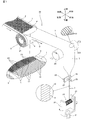
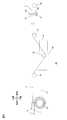
- FIG. 1 is a perspective view of a spinning device as a first embodiment of a carbon nanotube web manufacturing apparatus of the present invention.
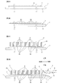
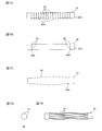
- FIG. 2A is an explanatory diagram for explaining an embodiment of a process for preparing the carbon nanotube array shown in FIG. 1, and shows a process of forming a catalyst layer on a substrate.
- FIG. 2B shows a process of heating the substrate to agglomerate the catalyst layer into a plurality of granules following FIG. 2A.
- FIG. 2C shows a process of growing a plurality of carbon nanotubes by supplying a raw material gas to a plurality of granular bodies following FIG. 2B.
- FIG. 2D shows a process of drawing a plurality of carbon nanotubes to prepare a carbon nanotube web following FIG.
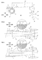
- FIG. 3A is a schematic configuration diagram of the spinning device shown in FIG. 1.
- FIG. 3B is a plan view of the spinning device shown in FIG. 3A and shows a state in which the tension roller has moved to the left side.
- FIG. 3C is a plan view of the spinning device shown in FIG. 3A and shows a state where the tension roller has moved to the right side.
- FIG. 4A is a schematic configuration diagram of a spinning device as a second embodiment of the carbon nanotube web manufacturing device of the present invention.
- FIG. 4B is a plan view of the spinning device shown in FIG. 4A and shows a state where the substrate has moved to the left side.
- FIG. 4C is a plan view of the spinning device shown in FIG.
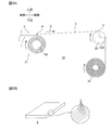
- FIG. 5 A is a schematic block diagram of the sheet manufacturing apparatus as 3rd Embodiment of the manufacturing apparatus of the carbon nanotube web of this invention.
- FIG. 5B is a perspective view of a carbon nanotube laminated sheet manufactured by the sheet manufacturing apparatus shown in FIG. 5A.
- FIG. 6 is a schematic configuration diagram of a fourth embodiment of the carbon nanotube web manufacturing apparatus of the present invention.
- FIG. 7A is a schematic configuration diagram of a first modification of the tension roller shown in FIG.
- FIG. 7B is a schematic configuration diagram of a second modification of the tension roller shown in FIG.
- FIG. 7C is a schematic configuration diagram of a third modification of the tension roller shown in FIG.
- FIG. 7A is a schematic configuration diagram of a first modification of the tension roller shown in FIG.
- FIG. 7B is a schematic configuration diagram of a second modification of the tension roller shown in FIG.
- FIG. 7C is a schematic configuration diagram of a third modification of the tension roller shown in FIG.
- FIG. 7D is a schematic configuration diagram of a fourth modification of the tension roller shown in FIG. 1.
- FIG. 7E is a front view of the tension roller shown in FIG. 7D.
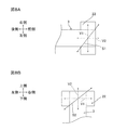
- FIG. 8A is an explanatory diagram for explaining vector components when the swinging direction of the carbon nanotube web shown in FIG. 1 is a direction connecting the front right side and the rear left side.
- FIG. 8B is an explanatory diagram for explaining a vector component when the swinging direction of the carbon nanotube web shown in FIG. 1 is a direction connecting the upper right side and the lower left side.
- FIG. 9A is an explanatory diagram for explaining the swinging direction of the carbon nanotube web shown in FIG. 1, and is a view of the swinging direction of the carbon nanotube web as viewed from the thickness direction of the substrate.
- FIG. 8A is an explanatory diagram for explaining vector components when the swinging direction of the carbon nanotube web shown in FIG. 1 is a direction connecting the front right side and the rear left side.
- FIG. 8B is an ex
- FIG. 9B is an explanatory diagram for explaining the swinging direction of the carbon nanotube web shown in FIG. 1, and is a view of the swinging direction of the carbon nanotube web as viewed from the pulling-out direction of the carbon nanotube web.
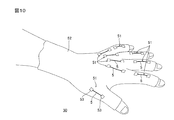
- FIG. 10 is a schematic configuration diagram of a wearable sensor including the carbon nanotube twisted yarn or aggregate shown in FIG.
- the first embodiment of the method for producing a carbon nanotube web of the present invention includes, for example, a carbon nanotube array 2 arranged on a substrate 1 as shown in FIG. It includes a step of preparing (preparation step) and a step of drawing out the carbon nanotube web 3 from the carbon nanotube array 2 (drawing step).
- a carbon nanotube array 2 arranged on the substrate 1 is prepared.
- a plurality of vertically aligned carbon nanotubes 4 are grown on the substrate 1 by chemical vapor deposition (CVD).
- a substrate 1 is prepared.
- substrate 1 is not specifically limited, For example, the well-known board
- the substrate 1 include a silicon substrate, a stainless steel substrate 8 on which a silicon dioxide film 7 is laminated, and preferably a stainless steel substrate 8 on which a silicon dioxide film 7 is laminated.
- the substrate 1 preferably has a long and flat strip shape from the viewpoint of continuous supply of the carbon nanotube array 2 described later, and the viewpoint of winding the substrate 1 described later. Therefore, preferably, it has flexibility.
- the substrate 1 is a stainless steel substrate 8 on which a silicon dioxide film 7 is laminated, and has a long and flat strip shape having flexibility. .
- the thickness direction of the substrate 1 is the vertical direction
- the long direction of the substrate 1 is the front-rear direction
- the width direction of the substrate 1 is the left-right direction.
- the direction arrow shown in each figure is used as a reference.
- the thickness of the stainless steel substrate 8 is, for example, 20 ⁇ m or more, preferably 50 ⁇ m or more, for example, 100 ⁇ m or less, preferably 80 ⁇ m or less
- the thickness of the silicon dioxide film 7 is, for example, 10 nm or more, preferably 100 nm or more, for example, 1 ⁇ m or less, preferably 500 nm or less.
- a catalyst layer 9 is formed on the substrate 1, preferably on the silicon dioxide film 7.
- a metal catalyst is formed on the substrate 1 (preferably the silicon dioxide film 7) by a known film formation method.
- metal catalyst examples include iron, cobalt, nickel and the like, and preferably iron. Such metal catalysts can be used alone or in combination of two or more.
- film forming method examples include vacuum evaporation and sputtering, and preferably vacuum evaporation.
- the catalyst layer 9 is disposed on the substrate 1.
- the substrate 1 is a stainless steel substrate 8 on which the silicon dioxide film 7 is laminated
- the silicon dioxide film 7 and the catalyst layer 9 are formed of a silicon dioxide precursor as described in, for example, Japanese Patent Application Laid-Open No. 2014-94856.
- the mixed solution in which the body solution and the metal catalyst precursor solution are mixed is applied to the stainless steel substrate 8, and then the mixed solution is phase-separated and then dried to form the mixed solution at the same time.
- the thickness (vertical dimension) of the catalyst layer 9 is, for example, 1 nm or more, preferably 2 nm or more, for example, 10 nm or less, preferably 4 nm or less.
- the substrate 1 on which the catalyst layer 9 is disposed is heated to, for example, 700 ° C. or more and 900 ° C. or less as shown in FIG. 2B.
- the catalyst layer 9 aggregates and becomes a plurality of granular materials 9A.
- the source gas contains a hydrocarbon gas having 1 to 4 carbon atoms (lower hydrocarbon gas).
- hydrocarbon gas having 1 to 4 carbon atoms include methane gas, ethane gas, propane gas, butane gas, ethylene gas, acetylene gas and the like, and preferably acetylene gas.
- the raw material gas can contain hydrogen gas, inert gas (for example, helium, argon, etc.), water vapor, etc., if necessary.
- inert gas for example, helium, argon, etc.
- the concentration of the hydrocarbon gas in the source gas is, for example, 1% by volume or more, preferably 30% by volume or more, for example, 90% by volume or less, preferably 50% by volume. % Or less.
- the supply time of the source gas is, for example, 1 minute or longer, preferably 5 minutes or longer, for example, 60 minutes or shorter, preferably 30 minutes or shorter.
- a plurality of carbon nanotubes 4 grow from each of the plurality of granular bodies 9A as a starting point.
- FIG. 2C for convenience, it is described that one carbon nanotube 4 grows from one granular body 9A.
- the present invention is not limited to this, and a plurality of carbon nanotubes 4 are formed from one granular body 9A. You may grow up.
- Such a plurality of carbon nanotubes 4 extend in the thickness direction (vertical direction) of the substrate 1 so as to be substantially parallel to each other on the substrate 1. That is, the plurality of carbon nanotubes 4 are oriented (orientated vertically) so as to be orthogonal to the substrate 1.
- the carbon nanotube 4 may be either a single-walled carbon nanotube or a multi-walled carbon nanotube, and is preferably a multi-walled carbon nanotube. These carbon nanotubes 4 can be used alone or in combination of two kinds.
- the average outer diameter of the carbon nanotube 4 is, for example, 1 nm or more, preferably 5 nm or more, for example, 100 nm or less, preferably 50 nm or less, and more preferably 20 nm or less.
- the average length (average axial direction dimension) of the carbon nanotubes 4 is, for example, 1 ⁇ m or more, preferably 100 ⁇ m or more, more preferably 200 ⁇ m or more, for example, 1000 ⁇ m or less, preferably 500 ⁇ m or less, more preferably 400 ⁇ m or less. It is.
- the number of layers, the average outer diameter, and the average length of the carbon nanotube 4 are measured by a known method such as Raman spectroscopic analysis or electron microscope observation.
- a carbon nanotube array 2 including a plurality of carbon nanotubes 4 is formed on the substrate 1.
- the carbon nanotube array 2 has a thickness in the vertical direction and has a substantially sheet shape extending along a plane direction (front-rear direction and left-right direction) orthogonal to the vertical direction.
- the carbon nanotube array 2 includes a plurality of rows 2A in the left-right direction in which a plurality of carbon nanotubes 4 are linearly arranged in the front-rear direction.
- the plurality of rows 2A are arranged in the left-right direction at an interval of, for example, 100 nm to 200 nm.
- the plurality of carbon nanotubes 4 are arranged in the front-rear direction, for example, 100 nm. They are arranged with an interval of ⁇ 200 nm. That is, in the carbon nanotube array 2, the plurality of carbon nanotubes 4 are densely arranged in the front-rear and left-right directions.
- the horizontal dimension L1 of the carbon nanotube array 2 is, for example, 5 mm or more, preferably 10 mm or more, more preferably 150 mm or more, for example, 500 mm or less, preferably 450 mm. It is as follows.
- the bulk density of the carbon nanotube array 2 is, for example, 10 mg / cm 3 or more, preferably 20 mg / cm 3 or more, for example, 60 mg / cm 3 or less, preferably 50 mg / cm 3 or less.
- the bulk density of the carbon nanotube array 2 is, for example, the mass per unit area (weight per unit: mg / cm 2 ) and the length of the carbon nanotube (SEM (manufactured by JEOL Ltd.)) Measured by).
- the carbon nanotube web 3 is pulled out from the carbon nanotube array 2 in the pulling direction D from the rear side toward the front side while being swung in the left-right direction.
- a tension roller 22 as an example of a contact member is prepared.
- the tension roller 22 has a cylindrical shape extending in the left-right direction.
- the outer diameter of the tension roller 22 is not particularly limited, and is, for example, 1 cm or more and 20 cm or less.
- the horizontal dimension of the tension roller 22 is not particularly limited as long as it is equal to the horizontal dimension L1 of the carbon nanotube array 2, and is preferably larger than the horizontal dimension L1 of the carbon nanotube array 2.
- the tension roller 22 is disposed at a front side with an interval with respect to the carbon nanotube array 2. That is, the tension roller 22 is disposed on the downstream side in the drawing direction D of the carbon nanotube web 3 with respect to the substrate 1 (carbon nanotube array 2).
- the distance between the tension roller 22 and the carbon nanotube array 2 is, for example, not less than 10 cm and not more than 20 cm.
- the tension roller 22 can rotate in the clockwise direction when viewed from the left side about its axis, and can reciprocate in the left-right direction as shown in FIGS. 3B and 3C. (Can be swung).
- the tension roller 22 is positioned at an initial position indicated by a virtual line in FIGS. 3B and 3C when stopped.
- the center in the left-right direction (axial direction) of the tension roller 22 and the center in the left-right direction of the carbon nanotube array 2 are aligned along the front-rear direction when viewed from the top-bottom direction. It is located on the same virtual line I extending along the front-rear direction.
- the tension roller 22 rotates in the clockwise direction when viewed from the left side during driving, and is located on the left side of the initial position and relatively leftmost (see the solid line in FIG. 3B).
- the robot moves continuously so as to reciprocate at a predetermined moving speed between a second position (see the solid line in FIG. 3C) located on the right side of the initial position and relatively farthest to the right.
- the tension roller 22 moves the movement amount L2 (oscillation width L2) to the left and right sides with respect to the initial position during driving.
- the amount of movement L2 of the tension roller 22 is not particularly limited as long as it is equal to or larger than the interval between the plurality of rows 2A in the carbon nanotube array 2 and not more than the horizontal dimension L1 of the carbon nanotube array 2. To preferably 1 mm or more, for example, 10 mm or less, and preferably 5 mm or less from the viewpoint of the drawing stability of the carbon nanotube web 3.
- the movement amount L2 of the tension roller 22 is preferably, for example, 1/50 or more, preferably 1/30 or more, more preferably 1/25 or more, with respect to the lateral dimension L1 of the carbon nanotube array 2. For example, it is 1/2 or less, preferably 1/10 or less, and more preferably 1/20 or less.
- the tension roller 22 preferably reciprocates so as to be symmetric with respect to an imaginary line I passing through the center in the left-right direction of the tension roller 22 at the initial position.
- the movement amounts L2 of the left and right sides of the tension roller 22 are the same.
- the moving speed of the tension roller 22 is, for example, 0.1 m / min or more, preferably 0.5 m / min or more, more preferably 1 m / min or more, for example, 100 m / min or less, preferably 10 m / min or less. More preferably, it is 5 m / less.
- the moving speed of the tension roller 22 is, for example, 1/1000 or more, preferably 1/100 or more, more preferably 1/10 or less, for example, 1 with respect to the drawing speed of the carbon nanotube web 3 described later. / 1 or less, preferably 1/2 or less, and more preferably 1/5 or less.
- the frequency of the tension roller 22 (the number of reciprocations per unit time) is, for example, 5 times / minute or more, preferably 10 times / minute or more, more preferably 100 times / minute or more, and particularly preferably 150 times / minute. Times / minute or more, for example, 500 times / minute or less, preferably 250 times / minute or less.
- the carbon nanotube web 3 is pulled out from the carbon nanotube array 2 and brought into contact with the tension roller 22.
- the carbon nanotubes 4 positioned at the front end of each row 2A of the carbon nanotube array 2 are collectively held by a drawing tool (not shown), and the thickness of the substrate 1 is increased. Pulling in the direction intersecting (intersecting) the direction, preferably toward the front side.
- the pulled carbon nanotubes 4 are pulled out from the corresponding granular material 9A as shown in FIG. 2D.
- the carbon nanotube 4 adjacent in the front-rear direction to the carbon nanotube 4 to be pulled out is a carbon from which one end (lower end) of the carbon nanotube 4 is pulled out due to frictional force and van der Waals force with the carbon nanotube 4 to be pulled out. It is attached to one end (lower end) of the nanotube 4 and pulled out from the corresponding granular material 9A.
- one end (lower end) of the carbon nanotube 4 with the carbon nanotube 4 attached to one end (lower end) is pulled downstream in the pulling direction D, so that the other end (upper end) of the carbon nanotube 4 is pulled out in the pulling direction D. It tilts so as to go upstream, and adheres to the other end (upper end) of the adjacent carbon nanotube 4.
- the other end (upper end) of the carbon nanotube 4 with the carbon nanotube 4 attached to the other end (upper end) is pulled downstream in the drawing direction D, so that one end (lower end) is pulled from the corresponding granular material 9A. It is pulled out and attached to one end (lower end) of the adjacent carbon nanotube 4.
- the continuous carbon nanotubes 4 are attached to one end (lower end) or the other end (upper end) of the carbon nanotubes 4 in the extending direction of the carbon nanotube single yarn 10. Oriented along.
- the carbon nanotubes 4 are continuously connected one by one to form the carbon nanotube single yarn 10, but actually, the carbon nanotubes 4 are composed of a plurality of carbon nanotubes 4.
- a bundle (bundle) is continuously connected to form a carbon nanotube single yarn 10.
- Such a carbon nanotube single yarn 10 is a non-twisted yarn that is not twisted and has a yarn shape (linear shape). That is, the twist angle of the carbon nanotube single yarn 10 is approximately 0 °.
- the outer diameter of the carbon nanotube single yarn 10 is, for example, 5 nm or more, preferably 8 nm or more, for example, 100 nm or less, preferably 80 nm or less, and more preferably 50 nm or less.
- the carbon nanotube single yarn 10 intersects with the extending direction of the carbon nanotube single yarn 10 because the carbon nanotubes 4 in each row 2A are pulled out simultaneously and in parallel. A plurality are arranged in parallel in the direction of crossing.
- the plurality of carbon nanotube single yarns 10 extend in the front-rear direction and are arranged in parallel in the left-right direction. Accordingly, the plurality of carbon nanotube single yarns 10 arranged in parallel have a substantially sheet shape and are formed as the carbon nanotube web 3.
- the carbon nanotube web 3 is drawn out such that a plurality of carbon nanotube single yarns 10 are arranged in parallel.
- the carbon nanotube web 3 is brought into contact with the tension roller 22. Specifically, the carbon nanotube web 3 is drawn in the circumferential direction of the tension roller 22 at the initial position so as to be positioned on the peripheral surface 22A (an example of the surface) of the tension roller 22.
- the carbon nanotube web 3 has a central angle in the tension roller 22 in the range of, for example, 5 ° to 180 °, preferably in the range of 10 ° to 150 °, and more preferably 60 °. It contacts the circumferential surface 22A of the tension roller 22 in the range of ⁇ 120 °.
- the upstream end portion in the moving direction (the upstream end portion in the clockwise direction in the left side view) of the portion of the carbon nanotube web 3 that contacts the peripheral surface 22A of the tension roller 22 is referred to as a contact upstream end portion X.
- the contact upstream end portion X of the carbon nanotube web 3 is disposed at a front side with an interval with respect to the drawing position P of the carbon nanotube web 3 as shown in FIGS. 3A and 3B.
- the distance L3 between the front-rear direction between the contact upstream end X of the carbon nanotube web 3 and the drawing position P of the carbon nanotube web 3 is, for example, not less than 10 cm and not more than 20 cm.
- the carbon nanotube web 3 positioned between the pulling position P and the contact upstream end X in a state where the tension roller 22 is in the initial position is referred to as a reference carbon nanotube web 3A (see phantom lines in FIGS. 3B and 3C).
- the reference carbon nanotube web 3A (that is, the plurality of carbon nanotube single yarns 10) extends along the front-rear direction when viewed from the upper-lower direction.
- the tension roller 22 is reciprocated in the left-right direction while restricting the movement of the substrate 1 in the left-right direction.
- the carbon nanotube web 3 is rotated so that tension is applied to the carbon nanotube web 3 between the carbon nanotube array 2 and the tension roller 22 by rotating the tension roller 22 clockwise in a left side view.
- the carbon nanotube web 3 is continuously drawn out from the carbon nanotube array 2 while oscillating in the left-right direction due to friction between the circumferential surface 22A of the tension roller 22 and the carbon nanotube web 3.
- the tension roller 22 swings (reciprocates in the left-right direction), so that the carbon nanotube web 3 is moved in the left-right direction (the thickness direction of the substrate 1 and the carbon nanotube web 3 is pulled out). Oscillate in a direction perpendicular to both directions D. Therefore, the left-right direction is an example of the swinging direction of the carbon nanotube web 3.
- the carbon nanotube web 3 positioned between the drawing position P and the contact upstream end X in a state where the tension roller 22 is in the first position or the second position is referred to as the swinging carbon nanotube web 3B (FIGS. 3B and 3B). 3C solid line reference).
- the carbon nanotube single yarn 10 of the swinging carbon nanotube web 3B swings from the carbon nanotube single yarn 10 of the reference carbon nanotube web 3A with the pulling position P as a fulcrum so as to be inclined with respect to the front-rear direction.
- the swing angle ⁇ formed by the carbon nanotube single yarn 10 of the reference carbon nanotube web 3A and the carbon nanotube single yarn 10 of the swinging carbon nanotube web 3B is arctan (the amount of movement L2 / the upstream end of the contact of the tension roller 22).
- the distance L3) between X and the drawing position P is, for example, 0.0003 ° or more, preferably 0.01 ° or more, more preferably 0.1 ° or more, for example, 6 ° or less, preferably Is 3 ° or less, more preferably 1 ° or less.
- the carbon nanotube web 3 is continuously drawn out from the carbon nanotube array 2 on the substrate 1 while being swung in the left-right direction.
- the drawing speed of the carbon nanotube web 3 is, for example, 10 mm / min or more, preferably 100 mm / min or more, more preferably 300 mm / min or more, for example, 10,000 mm / min or less, preferably 1000 mm / min or less, Preferably, it is 700 mm / min or less.
- the substrate 1 is conveyed so as to move downstream in the drawing direction D at the drawing position P of the carbon nanotube web 3, and the carbon nanotube array 2 is moved to the drawing position P. Is supplied continuously.
- the moving speed of the substrate 1 at the pulling position P is appropriately adjusted so that the pulling position P of the carbon nanotube web 3 is maintained at substantially the same position in the pulling direction D, for example, 0.5 mm / min or more 1 .5 mm / min or less.
- the substrate 1 that has passed through the extraction position P and from which the carbon nanotube array 2 has been peeled is preferably wound up as shown in FIG. More specifically, the take-up shaft 25 takes up and collects the substrate 1 that has passed through the drawing position P.
- the winding shaft 25 has a cylindrical shape extending in the left-right direction.
- the winding shaft 25 can rotate around its axis.
- the take-up shaft 25 is disposed at a lower side with respect to the drawing position P of the carbon nanotube web 3.
- the take-up shaft 25 rotates in the clockwise direction when viewed from the left side, thereby supplying driving force to the substrate 1 and moving the substrate 1 as described above. Convey at high speed and take up.
- the substrate 1 can be preferably transported by winding the substrate 1 on which the carbon nanotube array 2 is formed around a roll shaft and winding the substrate 1 fed from the roll shaft around a winding shaft 25. .
- the carbon nanotube array 2 can be sequentially formed on the substrate 1 to be transported by a roll-to-roll method. Specifically, the substrate 1 on which the carbon nanotube array 2 is not formed is wound around a roll shaft, the substrate 1 is transported from the roll shaft toward the winding shaft 25, and is transported between the roll shaft and the winding shaft 25. The carbon nanotube array 2 can also be sequentially formed on the substrate 1 to be formed.
- the carbon nanotube web 3 is continuously manufactured, and the substrate 1 from which the carbon nanotube array 2 is peeled is continuously collected.
- the tension roller 22 is passed so that the carbon nanotube web 3 drawn on the tension roller 22 passes over the tension roller 22. Pull out from.
- the carbon nanotube web 3 is rotated to twist a plurality of carbon nanotube single yarns 10 (processing step). Thereby, the carbon nanotube twisted yarn 5 is manufactured.
- the outer diameter of the carbon nanotube twisted yarn 5 is, for example, 5 ⁇ m or more, preferably 30 ⁇ m or more, for example, 80 ⁇ m or less, preferably 60 ⁇ m or less, and more preferably 40 ⁇ m or less.
- the bulk density of the carbon nanotube twisted yarn 5 is, for example, 0.6 g / cm 3 or more, preferably more than 0.6 g / cm 3 , more preferably 0.8 g / cm 3 or more, for example, 2. 0 g / cm 3 or less.
- the carbon nanotube twisted yarn 5 manufacturing method is continuously performed by a spinning device 20 as an example of a carbon nanotube web manufacturing device as shown in FIG.
- the spinning device 20 includes a web manufacturing unit 21 and a spinning unit 23.
- the web manufacturing unit 21 is disposed in the rear portion of the spinning device 20 and is configured to continuously pull out the carbon nanotube web 3 from the carbon nanotube array 2.
- the web manufacturing unit 21 includes a substrate 1 on which the carbon nanotube array 2 is disposed, a drawing tool (not shown), the winding shaft 25, and the tension roller 22.
- the substrate 1 is flexible and has a long and flat strip shape.
- the carbon nanotube array 2 is arranged on the substrate 1 so as to extend in the front-rear direction.
- the substrate 1 is restricted from moving in the left-right direction in the web manufacturing unit 21.
- the take-up shaft 25 is disposed below the front end portion of the substrate 1. A front end portion of the substrate 1 is fixed to the peripheral surface of the winding shaft 25.
- the tension roller 22 is disposed with a space in front of the front end portion of the carbon nanotube array 2.
- the spinning unit 23 is disposed at a lower interval with respect to the tension roller 22 and includes a converging unit 26 and a collecting unit 24.
- the converging part 26 is arranged with a space on the lower side with respect to the tension roller 22, and includes a support plate 27 and a pair of shafts 28.
- the support plate 27 has a substantially rectangular plate shape in front view extending in the left-right direction.
- the pair of shafts 28 are arranged on the front surface of the support plate 27 at a slight distance from each other in the left-right direction.
- the shaft 28 has a substantially cylindrical shape extending in the front-rear direction, and is supported by the support plate 27 so as to be relatively rotatable around the axis.
- the collection unit 24 is arranged with a gap on the lower side with respect to the convergence unit 26.
- the collection unit 24 includes a rotation unit 30, a bobbin shaft 29, and a rotation shaft 31.
- Rotating portion 30 has a substantially U-shape in front view that opens upward.
- the bobbin shaft 29 is disposed between the left and right side walls of the rotating unit 30.
- the bobbin shaft 29 has a substantially cylindrical shape extending in the left-right direction, and is rotatably supported on the left and right side walls of the rotating unit 30.
- the rotating shaft 31 is disposed below the rotating unit 30.
- the rotating shaft 31 has a substantially cylindrical shape extending in the vertical direction, and an upper end portion thereof is fixed to the center in the left-right direction of the lower wall of the rotating portion 30. As a result, the rotating unit 30 can rotate around the rotating shaft 31, that is, the axis along the vertical direction.
- the carbon nanotubes 4 in each row 2A are pulled out from the carbon nanotube array 2 toward the front side simultaneously and in parallel by a drawing tool (not shown).
- the plurality of carbon nanotube single yarns 10 are pulled out from the carbon nanotube array 2 as substantially sheet-shaped carbon nanotube webs 3 arranged in parallel in the left-right direction. That is, the spinning device 20 includes the carbon nanotube web 3 at the time of driving.
- the carbon nanotube web 3 is drawn approximately 1/4 turn from the upper end portion of the tension roller 22 toward the front end portion in the circumferential direction of the tension roller 22. Thereafter, the carbon nanotube web 3 is drawn downward from the tension roller 22 so as to pass over the tension roller 22 and is passed between the pair of shafts 28.
- the carbon nanotube web 3 that is, the plurality of carbon nanotube single yarns 10 are bundled in a linear shape (yarn shape). Then, the lower ends of the bundled carbon nanotube single yarns 10 are fixed to the bobbin shaft 29 of the recovery unit 24.
- the carbon nanotube web 3 is tensioned by the tension roller 22 between the carbon nanotube array 2 and the tension roller 22, and between the tension roller 22 and the collection unit 24.
- the carbon nanotube web 3 is pulled by the rotation of the tension roller 22 and the thread winding shaft 29, pulled out from the carbon nanotube array 2 at the above-described pulling speed, and conveyed, and the substrate 1 is attached to the winding shaft 25. By rotation, it is conveyed at the above moving speed. That is, the tension roller 22 and the thread winding shaft 29 function as a transport unit that pulls out and transports the carbon nanotube web 3.
- the substrate 1 continuously supplies the carbon nanotube array 2 to the drawing position P, passes through the drawing position P, and is then wound around the winding shaft 25.
- the winding shaft 25 is configured to move downward as the winding of the substrate 1 proceeds.
- the carbon nanotube web 3 is continuously drawn out from the carbon nanotube array 2 at the drawing position P.
- the carbon nanotube web 3 passes over the tension roller 22, is then sent downward from the tension roller 22, passes through a pair of shafts 28 and is bundled with the converging unit 26, and then rotates the rotation shaft 31. Thus, while rotating and twisting in a clockwise direction in plan view, it moves downward and is wound around the bobbin shaft 29.
- the rotation speed (circumferential speed) of the rotating unit 30 is, for example, 1000 rpm or more, preferably 2000 rpm or more, for example, 5000 rpm or less, preferably 4000 rpm or less.
- the carbon nanotube twisted yarn 5 is processed.
- Such a carbon nanotube twisted yarn 5 is used for various industrial products such as a woven fabric (sheet) in which carbon fiber is used and a conductive wire of an electric device (for example, a motor, a transformer, a sensor, etc.).
- a woven fabric sheet
- an electric device for example, a motor, a transformer, a sensor, etc.
- the carbon nanotube twisted yarn 5 is used for a wearable sensor 50 as shown in FIG.
- the wearable sensor 50 is configured to detect the movement of the detection subject's hand (for example, bending and stretching of a finger), and includes a mounting unit 52, a sensor unit 51 having the carbon nanotube twisted yarn 5, and a sensor body (see FIG. Not shown).
- the mounting portion 52 is formed in a glove shape from a stretchable resin material or knit material.
- the mounting unit 52 can be mounted on the hand of the person to be detected.
- a plurality of sensor units 51 are provided corresponding to the joints of the fingers of the person to be detected.
- the sensor unit 51 includes a pair of electrode pads 53 and a carbon nanotube twisted yarn 5.
- the pair of electrode pads 53 are arranged at intervals in each part of the mounting part 52. Each of the pair of electrode pads 53 is provided on the mounting portion 52 so as to come into contact with the fingers of the detection target person in a state where the wearable sensor 50 is mounted on the detection target person's hand. Although not shown, the electrode pad 53 is electrically connected to the sensor body via a wiring.
- the carbon nanotube twisted yarn 5 is laid between a pair of electrode pads 53 and electrically connects the pair of electrode pads 53.
- the carbon nanotube web 3 is pulled out from the carbon nanotube array 2 toward the front side while being swung in the left-right direction.
- the density difference may occur in each part of the carbon nanotube array 2 due to the maximization of the granular material 9A of the catalyst layer 9 or the poor wettability of the catalyst layer 9 due to local contamination of the substrate 1 or the like. .
- the interval between the carbon nanotubes 4 adjacent to each other becomes large, so the carbon nanotube web 3 is not pulled out well, and a part of the carbon nanotube array 2 is In some cases, it may remain on the substrate 1 without being peeled off from the substrate 1.
- the carbon nanotube array 2 includes a portion where the density is locally small, a plurality of carbon nanotubes 4 are adjacent to each other in the surroundings, particularly in the left-right direction, at the extraction position P of the carbon nanotube web 3. Contact with the nanotubes 4 is ensured.
- the carbon nanotubes 4 adjacent to each other act at the drawing position P of the carbon nanotube web 3 so as to be close to each other, and a plurality of carbon nanotubes 4 can be stably pulled out from the carbon nanotube array 2.
- the carbon nanotube web 3 can be made uniform, and the carbon nanotube array 2 can be prevented from remaining on the substrate 1, so that the production efficiency of the carbon nanotube web 3 can be improved.
- the tension roller 22 is a roller having a cylindrical shape. Therefore, as shown in FIG. 3A, the carbon nanotube web 3 can be brought into contact with the circumferential surface of the tension roller 22.
- the contact area between the carbon nanotube web 3 and the tension roller 22 can be improved. Accordingly, even if the tension roller 22 swings in a state where the carbon nanotube web 3 is in contact with the tension roller 22, it is possible to reliably suppress the movement of the carbon nanotube web 3 on the tension roller 22.
- the carbon nanotube web 3 is processed after passing over the tension roller 22 without being processed.
- the plurality of carbon nanotube single yarns 10 in the carbon nanotube web 3 are arranged in parallel in a direction intersecting (intersecting) with the extending direction of the carbon nanotube single yarn 10 between the drawing position P of the carbon nanotube web 3 and the tension roller 22.
- the state of arrangement is substantially maintained.
- the tension roller 22 can suppress the force resulting from the processing from acting on the drawing position P of the carbon nanotube web 3. . As a result, stable pulling out of the carbon nanotube web 3 can be ensured.
- the carbon nanotube web 3 is smoothly processed into the carbon nanotube twisted yarn 5 by a simple method of twisting together as shown in FIG. Therefore, the productivity of the carbon nanotube twisted yarn 5 can be improved.
- the carbon nanotube web 3 is continuously pulled out from the carbon nanotube array 2 while being swung in the moving direction of the tension roller 22.
- the uniformized carbon nanotube web 3 can be continuously produced, and the carbon nanotube array 2 can be prevented from remaining on the substrate 1, and the production efficiency of the carbon nanotube web 3 can be improved.
- the substrate 1 has a long and flat band shape, and is taken up by the take-up shaft 25 after passing through the draw position P in the drawing process of the carbon nanotube web 3.
- the present invention is not limited to this, and in the second embodiment, the substrate 1 may not be wound in the drawing process of the carbon nanotube web 3.
- the shape of the substrate 1 is not particularly limited, and the substrate 1 may not have flexibility.
- the movement of the substrate 1 is restricted in the left-right direction, and the tension roller 22 is reciprocated in the left-right direction.
- the present invention is not limited to this, and in the second embodiment, as shown in FIGS. 4B and 4C, in the drawing process of the carbon nanotube web 3, the movement of the tension roller 22 in the left-right direction is restricted, and the substrate 1 is It is reciprocated in the left-right direction.
- the substrate 1 is positioned between a first position (see the solid line in FIG. 4B) that is relatively leftmost and a second position (see the solid line in FIG. 4C) that is relatively rightmost. It moves continuously so as to reciprocate at the above moving amount L2 and moving speed.
- the substrate 1 is swung in the left-right direction with the carbon nanotube web 3 in contact with the tension roller 22.
- the carbon nanotube web 3 can be rocked stably and reliably.
- the spinning device 20 includes a web manufacturing unit 21 and a spinning unit 23.
- the web manufacturing unit 21 includes a substrate 1 that supports the carbon nanotube array 2, a drawing tool (not shown), and a tension roller 22.
- the shape of the substrate 1 is not particularly limited, and can be reciprocated (oscillated) in the left-right direction.
- the tension roller 22 is restricted from moving in the left-right direction in the web manufacturing unit 21.
- the substrate 1 reciprocates in the left-right direction while the carbon nanotube web 3 is in contact with the tension roller 22, and the bobbin shaft 29 and the tension roller 22 convey the carbon nanotube web 3.
- the carbon nanotube web 3 is continuously pulled out from the carbon nanotube array 2 while being swung in the left-right direction.
- the homogenized carbon nanotube web 3 can be continuously produced, and the carbon nanotube array 2 can be prevented from remaining on the substrate 1, and the production efficiency of the carbon nanotube web 3 can be improved.
- the carbon nanotube web 3 is processed into the carbon nanotube twisted yarn 5, but in the third embodiment, the carbon nanotube web 3 is assembled as shown in FIG. 5B. It is processed into a carbon nanotube laminated sheet 6 as an example of a body.
- a winding shaft 34 as an example of a conveying member is prepared.
- the winding shaft 34 has a cylindrical shape extending in the left-right direction.
- the winding shaft 34 is disposed downstream of the tension roller 22 in the conveyance direction of the carbon nanotube web 3.
- the carbon nanotube web 3 is pulled out from the carbon nanotube array 2 while being swung in the left-right direction, then passed over the tension roller 22, and then the front end portion (free end portion) of the carbon nanotube web 3 is wound. It fixes to the surrounding surface of the rotating shaft 34. FIG. Thereafter, the winding shaft 34 is rotated in the clockwise direction in the left side view.
- the carbon nanotube web 3 is pulled out from the carbon nanotube array 2 and conveyed at the above-described pulling speed. Thereafter, the carbon nanotube web 3 is sequentially wound around the circumferential surface of the winding shaft 34.
- the carbon nanotube web 3 wound around the winding shaft 34 is cut in the left-right direction with a cutting blade (for example, a razor, a cutter blade, etc.), and detached from the winding shaft 34.
- a cutting blade for example, a razor, a cutter blade, etc.
- the carbon nanotube laminated sheet 6 has a plurality of carbon nanotube webs 3 laminated in the thickness direction.
- the number of laminated carbon nanotube webs 3 is, for example, 5 layers or more, preferably 10 layers or more, for example, 1000 layers or less, preferably 500 layers or less.
- the thickness of the carbon nanotube laminated sheet 6 is, for example, 0.01 ⁇ m or more, preferably 5 ⁇ m or more, for example, 500 ⁇ m or less, preferably 200 ⁇ m or less.
- Such a carbon nanotube laminated sheet 6 can be continuously manufactured by a sheet manufacturing apparatus 33 as shown in FIG. 5A.
- the sheet manufacturing apparatus 33 is the same as the spinning apparatus 20 except that it includes a winding shaft 34 instead of the spinning unit 23. That is, the sheet manufacturing apparatus 33 includes the web manufacturing unit 21 and the winding shaft 34.
- the winding shaft 34 is disposed at a lower side with respect to the tension roller 22.
- the carbon nanotube web 3 can be smoothly processed by a simple method of winding and cutting the carbon nanotube web 3 around the winding shaft 34.
- the laminated carbon nanotube sheet 6 can be manufactured. Therefore, the productivity of the carbon nanotube multilayer sheet 6 can be improved.
- the carbon nanotube web 3 is immersed in a volatile liquid after passing over the tension roller 22.
- Examples of the volatile liquid include water and an organic solvent, and preferably an organic solvent.
- Examples of the organic solvent include lower (C1-3) alcohols (for example, methanol, ethanol, propanol, etc.), ketones (for example, acetone), ethers (for example, diethyl ether, tetrahydrofuran, etc.), alkyl esters ( For example, ethyl acetate etc.), halogenated aliphatic hydrocarbons (eg chloroform, dichloromethane etc.), polar aprotics (eg N-methylpyrrolidone, dimethylformamide etc.) and the like.
- C1-3 lower (C1-3) alcohols (for example, methanol, ethanol, propanol, etc.), ketones (for example, acetone), ethers (for example, diethyl ether, tetrahydrofuran, etc.), alkyl esters ( For example, ethyl acetate etc.), halogenated
- volatile liquids lower alcohols are preferable, and ethanol is more preferable.
- Such volatile liquids can be used alone or in combination of two or more.
- fine particles can be dispersed and the resin material can be dissolved.
- the fine particles include organic fine particles (eg, silicone fine particles, acrylic fine particles, urethane fine particles), inorganic fine particles (eg, silica, titanium oxide, calcium carbonate), metal fine particles (eg, gold fine particles, silver fine particles, copper fine particles). And carbon fine particles (for example, carbon black).
- organic fine particles eg, silicone fine particles, acrylic fine particles, urethane fine particles
- inorganic fine particles eg, silica, titanium oxide, calcium carbonate
- metal fine particles eg, gold fine particles, silver fine particles, copper fine particles
- carbon fine particles for example, carbon black
- thermoplastic resins eg, polyester resin, polycarbonate resin, fluorine resin, etc.
- thermosetting resins eg, silicone resin, epoxy resin, urethane resin, etc.
- the spinning device 20 includes an immersion unit 40 between the tension roller 22 and the converging unit 26.
- the immersion unit 40 includes an immersion tank 41 and a plurality of shaft members 42.
- the immersion tank 41 has a substantially box shape opened upward, and the volatile liquid is stored therein.
- the plurality of shaft members 42 are arranged so that the carbon nanotube web 3 is immersed in a volatile liquid in the immersion tank 41.
- the carbon nanotube web 3 is immersed in a volatile liquid. Then, when the volatile liquid is vaporized, in each carbon nanotube single yarn 10, the plurality of carbon nanotubes 4 aggregate together and the plurality of carbon nanotube single yarns 10 aggregate together. As a result, the density of the carbon nanotube web 3 can be improved.
- the fourth embodiment as described above can achieve the same effects as the first embodiment.
- the sheet manufacturing apparatus 33 can also include the immersion unit 40.
- the peripheral surface 22A of the tension roller 22 is a smooth surface without unevenness, but preferably has an uneven shape as shown in FIGS. 7A and 7B.
- the peripheral surface 22A of the tension roller 22 is formed in an uneven shape.
- the plurality of protrusions 45 are arranged corresponding to the portion of the peripheral surface 22A of the tension roller 22 where the carbon nanotube web 3 is arranged.
- the plurality of protrusions 45 are portions (left end portion and right end portion) of the peripheral surface 22A of the tension roller 22 excluding both left and right end portions so as to correspond to the entire left and right direction of the carbon nanotube web 3.
- the plurality of protrusions 45 include a plurality of rows 45A in which the plurality of protrusions 45 are arranged in the circumferential direction of the tension roller 22 with an interval in the left-right direction.
- the interval between the plurality of rows 45A is, for example, 1/100 or more and 1/10 or less with respect to the movement amount L2 of the tension roller 22.
- the plurality of protrusions 45 may include only one pair of the rows 45A at intervals in the left-right direction so as to correspond to the left and right ends of the carbon nanotube web 3. it can.
- Each of the plurality of protrusions 45 protrudes outward in the radial direction from the circumferential surface 22A of the tension roller 22 and has a substantially hemispherical shape.
- the height of the protrusion 45 is, for example, not less than 0.5 mm and less than 1 mm.
- the plurality of protrusions 45 are provided on the peripheral surface 22A of the tension roller 22 in this way, when the carbon nanotube web 3 is disposed on the peripheral surface 22A of the tension roller 22, the plurality of protrusions 45 are It enters between the plurality of carbon nanotube single yarns 10 in the nanotube web 3.
- peripheral surface 22A of the tension roller 22 may have an inclined surface 46 at a portion where the carbon nanotube web 3 is disposed as shown in FIG. 7C.
- the inclined surface 46 is disposed over the entire circumference in a portion (a portion between the left end portion and the right end portion) excluding the left and right ends of the peripheral surface 22A of the tension roller 22.
- the inclined surface 46 is inclined outward in the radial direction of the tension roller 22 toward the center of the tension roller 22 in the left-right direction. That is, the inclined surface 46 is inclined to the outside in the contact direction with the carbon nanotube web 3 as it goes inward in the left-right direction.
- the tension roller 22 has a taper shape having a smaller diameter from the central portion in the left-right direction toward the outer side in the left-right direction.
- the tension roller 22 or the substrate 1 swings in a state where the carbon nanotube web 3 is in contact with the tension roller 22, the carbon nanotube web 3 may gather inside in the left-right direction that is restrained by the swing.
- the tension roller 22 since the tension roller 22 has the inclined surface 46, the carbon nanotube web 3 moves toward the center in the left-right direction of the tension roller 22 when the tension roller 22 or the substrate 1 swings. It can suppress gathering.
- an adjustment member capable of appropriately adjusting the contact area with the carbon nanotube web 3 can be provided on the peripheral surface 22A of the tension roller 22.
- a plurality of protrusions 47 as an example of an adjustment member can be provided on the peripheral surface 22A of the tension roller 22.
- the plurality of protrusions 47 are formed on a portion (a portion between the left end portion and the right end portion) excluding the left and right end portions of the peripheral surface 22A of the tension roller 22 so as to correspond to the entire left and right direction of the carbon nanotube web 3. , Arranged over the entire circumference.
- each of the plurality of protrusions 47 protrudes from the circumferential surface 22A of the tension roller 22 toward the outside in the radial direction, and has a substantially arc shape in a side view.
- the plurality of protrusions 47 extend in the left-right direction, and are arranged at intervals in the circumferential direction of the tension roller 22.
- the contact area between the tension roller 22 and the carbon nanotube web 3 can be adjusted as appropriate. It can suppress sticking to.
- the tension roller 22 is an example of a contact member, but the contact member is not limited to this.
- the contact member may be a plate-like member.
- the carbon nanotube web 3 in the drawing process of the carbon nanotube web 3, the carbon nanotube web 3 is brought into contact with the tension roller 22, and the tension roller 22 reciprocates in the left-right direction.
- the present invention is not limited to this.
- the carbon nanotube array 2 can be pulled out.
- the tension roller 22 in the drawing process, is reciprocated in the left-right direction, and the carbon nanotube web 3 swings in the left-right direction.
- FIGS. 9A and 9B there is no particular limitation as long as it intersects (intersects) both the thickness direction of the substrate 1 and the drawing direction D of the carbon nanotube web 3.
- the swinging direction of the carbon nanotube web 3 includes at least a vector component in the left-right direction.
- the tension roller 22 reciprocates in the direction connecting the right front side and the left rear side, and the carbon nanotube web 3 swings in the direction connecting the right front side and the left rear side.
- the swing direction S1 of the carbon nanotube web 3 (specifically, the vector due to the swing of the carbon nanotube web 3) is decomposed into a vector component V1 along the left-right direction and a vector component V2 along the front-rear direction.
- the swing direction S1 includes a vector component V1 along the left-right direction.
- the swing direction S2 of the carbon nanotube web 3 (specifically, the vector due to the swing of the carbon nanotube web 3) is decomposed into a vector component V1 along the left-right direction and a vector component V2 along the up-down direction.
- the moving direction S2 includes a vector component V1 along the left-right direction.
- the swinging direction of the carbon nanotube web 3 is perpendicular to both the left and right directions (the thickness direction of the substrate 1 and the drawing direction D of the carbon nanotube web 3).
- Direction a direction connecting the upper right side and the lower left side, a direction connecting the upper left side and the lower right side, a direction connecting the right rear side and the left front side, a direction connecting the left rear side and the front right side, and the like.
- the spinning device 20 includes a web manufacturing unit 21 and a spinning unit 23, and pulls out the carbon nanotube web 3 from the carbon nanotube array 2, and the carbon nanotube web 3.
- the present invention is not limited to this.
- the drawing of the carbon nanotube web 3 from the carbon nanotube array 2 and the processing (spinning) of the carbon nanotube web 3 may be performed in separate steps.
- the carbon nanotube web 3 drawn out from the carbon nanotube array 2 is wound around the winding shaft 34
- the carbon nanotube web 3 drawn out from the winding shaft 34 is separately processed. Also good.
- the carbon nanotube web 3 is processed into the carbon nanotube twisted yarn 5.
- the present invention is not limited to this, and the carbon nanotube web 3 is made of carbon as an example of a carbon nanotube aggregate. It can also be processed into nanotube untwisted yarn.
- the carbon nanotube web 3 (a plurality of carbon nanotube single yarns 10) is passed through a die having a hole by, for example, a method described in Japanese Patent Application Laid-Open No. 2014-169521.
- Example 1 After a silicon dioxide film was laminated on a stainless steel substrate (stainless steel substrate), iron was deposited as a catalyst layer on the silicon dioxide film.
- the substrate has a long and flat band shape, the length in the longitudinal direction (vertical direction) of the substrate is 10 m, and the length in the width direction (lateral direction) of the substrate is 20 mm. The thickness of the substrate is 50 ⁇ m.
- the substrate was heated to a predetermined temperature, and a source gas (acetylene gas) was supplied to the catalyst layer.
- a source gas acetylene gas
- the plurality of carbon nanotubes extend so as to be substantially parallel to each other, and are aligned (vertically aligned) so as to be orthogonal to the substrate.
- the carbon nanotubes were multi-walled carbon nanotubes.
- the average outer diameter of the carbon nanotubes was about 12 nm
- the average length of the carbon nanotubes was about 300 ⁇ m
- the bulk density of the carbon nanotube array was about 40 mg / cm 3 .
- the carbon nanotube web was pulled out from the carbon nanotube array on the substrate.
- a plurality of carbon nanotube single yarns were arranged in parallel in the left-right direction.
- the average diameter of the carbon nanotube single yarn was about 60 to 80 nm.
- the carbon nanotube web was moved to the front side, and drawn around the peripheral surface of the tension roller having an uneven shape on the peripheral surface in the clockwise direction when viewed from the left side. At this time, the carbon nanotube web was disposed on the peripheral surface having a central angle of 90 ° in the tension roller.
- the distance between the contact upstream end of the carbon nanotube web and the drawing position of the carbon nanotube web was 15 cm.
- the tension roller was rotated in the clockwise direction when viewed from the left side and reciprocated (oscillated) in the left-right direction at a speed of 100 mm / min.
- the amount of movement of the tension roller was 1 mm on each of the left and right sides, and the number of reciprocations of the tension roller was 25 times / minute.
- the carbon nanotube web was pulled out at a speed of 500 mm / min while swinging in the left-right direction. (Drawing process).
- Comparative Example 1 A carbon nanotube web was prepared in the same manner as in Example 1 except that in the drawing step, the tension roller was not swung and the carbon nanotube web was pulled without being swung.
- the carbon nanotube web manufacturing method and carbon nanotube web manufacturing apparatus of the present invention can be suitably used for manufacturing carbon nanotube webs used in various industrial products.
- the method for producing an aggregate of carbon nanotubes of the present invention can be suitably used for producing an aggregate of carbon nanotubes used in various industrial products, and in particular, can be used for producing a carbon nanotube twisted yarn, a carbon nanotube laminated sheet, and the like. .
Landscapes
- Chemical & Material Sciences (AREA)
- Engineering & Computer Science (AREA)
- Materials Engineering (AREA)
- Nanotechnology (AREA)
- Organic Chemistry (AREA)
- Inorganic Chemistry (AREA)
- Manufacturing & Machinery (AREA)
- Mechanical Engineering (AREA)
- Textile Engineering (AREA)
- Carbon And Carbon Compounds (AREA)
Abstract
カーボンナノチューブウェブの製造方法は、基板上に配置され、基板に対して垂直に配向される複数のカーボンナノチューブからなるカーボンナノチューブアレイを準備する工程と、カーボンナノチューブアレイから、複数のカーボンナノチューブ単糸が並列配置されるように引き出されてなるカーボンナノチューブウェブを引き出す工程と、を含み、カーボンナノチューブウェブを引き出す工程において、カーボンナノチューブウェブを、基板の厚み方向およびカーボンナノチューブウェブの引出方向の両方向と交わる方向に揺動させる。
Description
本発明は、カーボンナノチューブウェブの製造方法、カーボンナノチューブ集合体の製造方法およびカーボンナノチューブウェブの製造装置に関する。
カーボンナノチューブは、優れた機械強度、熱伝導性および電気伝導性を有していることが知られている。また、そのようなカーボンナノチューブは高い紡績性能を有するために、複数のカーボンナノチューブからなるカーボンナノチューブアレイをウェブ状に引き出すことが検討されている。
例えば、基板上に、複数のカーボンナノチューブからなるカーボンナノチューブアレイを成長させた後、基板上のカーボンナノチューブアレイから、複数のカーボンナノチューブを引き出して、カーボンナノチューブフィルムを形成するカーボンナノチューブフィルムの製造方法が提案されている(例えば、特許文献1参照)。
そのカーボンナノチューブフィルムの製造方法では、カーボンナノチューブアレイにおいて互いに隣接するカーボンナノチューブが、連続して基板から引き出され、カーボンナノチューブの引き出しに伴なって、カーボンナノチューブアレイが基板から順次剥離される。
しかし、特許文献1に記載のカーボンナノチューブフィルムの製造方法では、カーボンナノチューブの引き出しにおいて、カーボンナノチューブアレイの一部(つまり、複数のカーボンナノチューブ)が、基板から剥離されずに、基板上に残存してしまう場合がある。
この場合、カーボンナノチューブがカーボンナノチューブアレイから一様に引き出されないため、カーボンナノチューブフィルムの各部において密度差が生じ、カーボンナノチューブフィルムの均一性を確保できないという不具合がある。
また、カーボンナノチューブアレイの一部が基板上に残存するので、カーボンナノチューブアレイの一部をカーボンナノチューブフィルムの製造に利用できず、カーボンナノチューブフィルムの生産性が低下してしまうという不具合がある。
そこで、本発明の目的は、カーボンナノチューブウェブの均一性の向上を図ることができながら、生産効率の向上を図ることができるカーボンナノチューブウェブの製造方法、カーボンナノチューブ集合体の製造方法およびカーボンナノチューブウェブの製造装置を提供することにある。
本発明[1]は、基板上に配置され、前記基板に対して垂直に配向される複数のカーボンナノチューブからなるカーボンナノチューブアレイを準備する工程と、前記カーボンナノチューブアレイから、複数のカーボンナノチューブ単糸が並列配置されるように引き出されてなるカーボンナノチューブウェブを引き出す工程と、を含み、前記カーボンナノチューブウェブを引き出す工程において、前記カーボンナノチューブウェブを、前記基板の厚み方向および前記カーボンナノチューブウェブの引出方向の両方向と交わる方向に揺動させる、カーボンナノチューブウェブの製造方法を含む。
このような方法によれば、カーボンナノチューブウェブを、基板の厚み方向およびカーボンナノチューブウェブの引出方向の両方向と交わる方向に揺動させながら、カーボンナノチューブアレイから引き出すので、カーボンナノチューブウェブの揺動が、複数のカーボンナノチューブ単糸を介して、カーボンナノチューブウェブのカーボンナノチューブアレイからの引出位置に作用する。
すると、カーボンナノチューブウェブの引出位置において、カーボンナノチューブアレイの複数のカーボンナノチューブが、周囲に隣接するカーボンナノチューブと確実に接触する。
これによって、カーボンナノチューブウェブの引出位置において、互いに隣接するカーボンナノチューブが相互に近接し合うように作用し、複数のカーボンナノチューブをカーボンナノチューブアレイから安定して引き出すことができる。
そのため、カーボンナノチューブウェブの均一化を図ることができるとともに、基板上にカーボンナノチューブアレイが残存することを抑制でき、カーボンナノチューブウェブの生産効率の向上を図ることができる。
本発明[2]は、前記カーボンナノチューブウェブを引き出す工程において、前記カーボンナノチューブウェブを、接触部材に接触させ、前記接触部材を揺動させることにより、前記カーボンナノチューブウェブを揺動させる、上記[1]に記載のカーボンナノチューブウェブの製造方法を含む。
このような方法によれば、カーボンナノチューブウェブを引き出す工程において、カーボンナノチューブウェブを、接触部材に接触させた後、接触部材を揺動させるので、カーボンナノチューブウェブを安定して確実に揺動させることができる。
本発明[3]は、前記カーボンナノチューブウェブを引き出す工程において、前記カーボンナノチューブウェブを、接触部材に接触させ、前記基板を揺動させることにより、前記カーボンナノチューブウェブを揺動させる、上記[1]に記載のカーボンナノチューブウェブの製造方法を含む。
このような方法によれば、カーボンナノチューブウェブを引き出す工程において、カーボンナノチューブウェブが接触部材に接触した状態で、基板を揺動させるので、カーボンナノチューブウェブを安定して確実に揺動させることができる。
本発明[4]は、接触部材における、前記カーボンナノチューブウェブと接触する表面が、凹凸形状を有している、上記[2]または[3]に記載のカーボンナノチューブウェブの製造方法を含む。
しかるに、カーボンナノチューブウェブが接触部材に接触した状態で、接触部材または基板が揺動すると、接触部材上のカーボンナノチューブウェブが横滑りしてしまい、カーボンナノチューブウェブの各部において密度差が生じてしまう場合がある。
一方、上記の方法によれば、接触部材の表面が凹凸形状を有しているので、カーボンナノチューブウェブが接触部材に接触した状態で、接触部材または基板が揺動しても、接触部材の表面の凹凸形状により、接触部材上のカーボンナノチューブウェブが横滑りすることを抑制できる。そのため、カーボンナノチューブウェブの均一性を確実に確保できる。
本発明[5]は、前記接触部材における、前記カーボンナノチューブウェブとの接触部分が、前記揺動方向の内側に向かうにつれて、前記カーボンナノチューブウェブとの接触方向外側に向かって傾斜する傾斜面を有する、上記[2]~[4]のいずれか一項に記載のカーボンナノチューブウェブの製造方法を含む。
しかるに、カーボンナノチューブウェブが接触部材に接触した状態で、接触部材または基板が揺動すると、カーボンナノチューブウェブが、揺動がより拘束される揺動方向の内側に集まるように移動する場合がある。
しかし、上記の方法によれば、接触部材の接触部分が傾斜面を有しているので、カーボンナノチューブウェブが接触部材に接触した状態で、接触部材または基板が揺動しても、接触部分の傾斜面により、接触部材上のカーボンナノチューブウェブが、揺動方向の内側に向かって集まることを抑制できる。そのため、カーボンナノチューブウェブの均一性をより一層確実に確保できる。
本発明[6]は、前記接触部材が、円柱形状を有するローラである、上記[2]~[5]のいずれ一項に記載のカーボンナノチューブウェブの製造方法を含む。
このような方法によれば、接触部材が円柱形状を有するローラであるので、カーボンナノチューブウェブを、ローラの周面に沿うように接触させることができる。
そのため、カーボンナノチューブウェブとローラとの接触面積の向上を図ることができる。その結果、カーボンナノチューブウェブがローラに接触した状態で、ローラまたは基板が揺動しても、ローラ上のカーボンナノチューブウェブが横滑りしてしまうことを確実に抑制できる。
本発明[7]は、上記[2]~[6]のいずれか一項に記載のカーボンナノチューブウェブの製造方法により製造されるカーボンナノチューブウェブを、前記接触部材上を通過させた後、加工する工程を含んでいる、カーボンナノチューブ集合体の製造方法を含む。
このような方法によれば、上記のように引き出されたカーボンナノチューブウェブが、加工されることなく、接触部材上を通過した後、加工される。
つまり、カーボンナノチューブウェブおける複数のカーボンナノチューブ単糸は、カーボンナノチューブウェブの引出位置とローラとの間において、カーボンナノチューブ単糸の延びる方向と交わる方向に並列配置される状態が維持されている。
しかるに、カーボンナノチューブウェブの引出位置と接触部材との間において、カーボンナノチューブウェブが、例えば、撚り合わされるなど加工されると、その加工に起因する力が、複数のカーボンナノチューブ単糸を介して、カーボンナノチューブウェブの引出位置に作用する。すると、カーボンナノチューブウェブの引き出しが不安定となる場合がある。
一方、上記の方法によれば、カーボンナノチューブウェブは、接触部材上を通過した後、加工されるので、その加工に起因する力が、カーボンナノチューブウェブの引出位置に作用することを、接触部材により抑制できる。そのため、カーボンナノチューブウェブの安定した引き出しを確保できる。
本発明[8]は、前記カーボンナノチューブウェブを加工する工程において、前記カーボンナノチューブウェブを撚り合わせて撚糸とする、上記[7]に記載のカーボンナノチューブ集合体の製造方法を含む。
このような方法によれば、カーボンナノチューブウェブを撚り合わせるという簡易な方法により、カーボンナノチューブウェブを円滑に加工でき、撚糸を製造できる。そのため、撚糸の生産性の向上を図ることができる。
本発明[9]は、前記カーボンナノチューブウェブを加工する工程は、円柱形状を有する巻回軸を準備する工程と、前記カーボンナノチューブウェブを、前記巻回軸の周面に複数周巻き付ける工程と、前記巻回軸の周面に複数周巻き付けられた前記カーボンナノチューブウェブを、前記巻回軸の軸線方向に切断して、シート形状に形成する工程と、を含む、上記[7]に記載のカーボンナノチューブ集合体の製造方法を含む。
このような方法によれば、カーボンナノチューブウェブを巻取軸に複数周巻き付け、切断するという簡易な方法により、カーボンナノチューブウェブを円滑に加工でき、複数のカーボンナノチューブウェブが積層されるシート(以下、カーボンナノチューブ積層シートとする。)を製造できる。そのため、カーボンナノチューブ積層シートの生産性の向上を図ることができる。
本発明[10]は、前記カーボンナノチューブウェブを加工する工程において、前記カーボンナノチューブウェブを、揮発性の液体に浸漬する、上記[7]に記載のカーボンナノチューブ集合体の製造方法を含む。
このような方法によれば、カーボンナノチューブウェブが揮発性の液体に浸漬されるので、揮発性の液体が気化することにより、各カーボンナノチューブ単糸において、複数のカーボンナノチューブが互いに凝集するとともに、複数のカーボンナノチューブ単糸が互いに凝集する。そのため、カーボンナノチューブウェブの密度の向上を図ることができる。
本発明[11]は、垂直に配向される複数のカーボンナノチューブからなるカーボンナノチューブアレイが配置される基板と、前記カーボンナノチューブアレイから、複数のカーボンナノチューブ単糸が並列配置されるように引き出されてなるカーボンナノチューブウェブと、前記基板に対して、前記カーボンナノチューブウェブの引き出し方向の下流に配置される接触部材と、を備え、前記接触部材または前記基板は、前記基板の厚み方向および前記カーボンナノチューブウェブの引出方向の両方向と交わる方向に揺動可能である、カーボンナノチューブウェブの製造装置を含む。
このような構成によれば、カーボンナノチューブウェブと接触する接触部材または基板が、基板の厚み方向およびカーボンナノチューブウェブの引出方向の両方向と交わる方向に揺動する。
そのため、接触部材にカーボンナノチューブウェブを接触させることで、カーボンナノチューブウェブが、接触部材または基板の揺動方向に揺動されながら、カーボンナノチューブアレイから連続して引き出される。
そのため、均一化されたカーボンナノチューブウェブが連続して製造できるとともに、基板上にカーボンナノチューブアレイが残存することを抑制でき、カーボンナノチューブウェブの生産効率の向上を図ることができる。
本発明のカーボンナノチューブウェブの製造方法では、カーボンナノチューブウェブの均一性の向上を図ることができながら、生産効率の向上を図ることができる。
本発明のカーボンナノチューブ集合体の製造方法では、カーボンナノチューブウェブを円滑に加工することができ、生産効率の向上を図ることができる。
本発明のカーボンナノチューブウェブの製造装置では、均一化されたカーボンナノチューブウェブを連続して製造でき、カーボンナノチューブウェブの生産効率の向上を図ることができる。
1.第1実施形態
(1)カーボンナノチューブウェブの製造方法
本発明のカーボンナノチューブウェブの製造方法の第1実施形態は、例えば、図1に示すように、基板1上に配置されるカーボンナノチューブアレイ2を準備する工程(調製工程)と、カーボンナノチューブアレイ2からカーボンナノチューブウェブ3を引き出す工程(引出工程)とを含んでいる。
(1)カーボンナノチューブウェブの製造方法
本発明のカーボンナノチューブウェブの製造方法の第1実施形態は、例えば、図1に示すように、基板1上に配置されるカーボンナノチューブアレイ2を準備する工程(調製工程)と、カーボンナノチューブアレイ2からカーボンナノチューブウェブ3を引き出す工程(引出工程)とを含んでいる。
このような製造方法では、まず、基板1上に配置されるカーボンナノチューブアレイ2を準備する。
カーボンナノチューブアレイ2を準備するには、例えば、図2A~図2Cに示すように、化学気相成長法(CVD法)により、基板1上に、垂直に配向される複数のカーボンナノチューブ4を成長させる。
より詳しくは、図2Aに示すように、まず、基板1を準備する。基板1は、特に限定されず、例えば、CVD法に用いられる公知の基板が挙げられ、市販品を用いることができる。基板1としては、例えば、シリコン基板や、二酸化ケイ素膜7が積層されるステンレス基板8などが挙げられ、好ましくは、二酸化ケイ素膜7が積層されるステンレス基板8が挙げられる。
基板1は、図1に示すように、後述するカーボンナノチューブアレイ2の連続供給の観点から、好ましくは、長尺かつ平帯形状を有しており、かつ、後述する基板1の巻き取りの観点から、好ましくは、可撓性を有している。
第1実施形態では、基板1は、図1~図2Dに示すように、二酸化ケイ素膜7が積層されるステンレス基板8であり、可撓性を有する長尺かつ平帯形状を有している。
なお、以下の説明において、基板1の厚み方向を上下方向とし、基板1の長尺方向を前後方向とし、基板1の幅方向を左右方向とする。具体的には、各図に示す方向矢印を基準とする。
基板1が、二酸化ケイ素膜7が積層されるステンレス基板8である場合、ステンレス基板8の厚みは、例えば、20μm以上、好ましくは、50μm以上、例えば、100μm以下、好ましくは、80μm以下であり、二酸化ケイ素膜7の厚みは、例えば、10nm以上、好ましくは、100nm以上、例えば、1μm以下、好ましくは、500nm以下である。
そして、図2Aに示すように、基板1上、好ましくは、二酸化ケイ素膜7上に触媒層9を形成する。基板1上に触媒層9を形成するには、金属触媒を、公知の成膜方法により、基板1(好ましくは、二酸化ケイ素膜7)上に成膜する。
金属触媒としては、例えば、鉄、コバルト、ニッケルなどが挙げられ、好ましくは、鉄が挙げられる。このような金属触媒は、単独使用または2種類以上併用することができる。成膜方法としては、例えば、真空蒸着およびスパッタリングが挙げられ、好ましくは、真空蒸着が挙げられる。
これによって、基板1上に触媒層9が配置される。なお、基板1が、二酸化ケイ素膜7が積層されるステンレス基板8である場合、二酸化ケイ素膜7および触媒層9は、例えば、特開2014-94856号公報に記載されるように、二酸化ケイ素前駆体溶液と金属触媒前駆体溶液とが混合される混合溶液を、ステンレス基板8に塗布した後、その混合液を相分離させ、次いで、乾燥することにより、同時に形成することもできる。
触媒層9の厚み(上下方向寸法)は、例えば、1nm以上、好ましくは、2nm以上、例えば、10nm以下、好ましくは、4nm以下である。
次いで、触媒層9が配置される基板1を、図2Bに示すように、例えば、700℃以上900℃以下に加熱する。これにより、触媒層9が、凝集して、複数の粒状体9Aとなる。
そして、加熱された基板1に、図2Cに示すように、原料ガスを供給する。原料ガスは、炭素数1~4の炭化水素ガス(低級炭化水素ガス)を含んでいる。炭素数1~4の炭化水素ガスとしては、例えば、メタンガス、エタンガス、プロパンガス、ブタンガス、エチレンガス、アセチレンガスなどが挙げられ、好ましくは、アセチレンガスが挙げられる。
また、原料ガスは、必要により、水素ガスや、不活性ガス(例えば、ヘリウム、アルゴンなど)、水蒸気などを含むこともできる。
原料ガスが水素ガスや不活性ガスを含む場合、原料ガスにおける炭化水素ガスの濃度は、例えば、1体積%以上、好ましくは、30体積%以上、例えば、90体積%以下、好ましくは、50体積%以下である。原料ガスの供給時間としては、例えば、1分以上、好ましくは、5分以上、例えば、60分以下、好ましくは、30分以下である。
これによって、複数の粒状体9Aのそれぞれを起点として、複数のカーボンナノチューブ4が成長する。なお、図2Cでは、便宜上、1つの粒状体9Aから、1つのカーボンナノチューブ4が成長するように記載されているが、これに限定されず、1つの粒状体9Aから、複数のカーボンナノチューブ4が成長してもよい。
このような複数のカーボンナノチューブ4は、基板1上において、互いに略平行となるように、基板1の厚み方向(上下方向)に延びている。つまり、複数のカーボンナノチューブ4は、基板1に対して直交するように配向(垂直に配向)されている。
カーボンナノチューブ4は、単層カーボンナノチューブおよび多層カーボンナノチューブのいずれであってもよく、好ましくは、多層カーボンナノチューブである。これらカーボンナノチューブ4は、単独使用または2種類を併用することができる。
カーボンナノチューブ4の平均外径は、例えば、1nm以上、好ましくは、5nm以上、例えば、100nm以下、好ましくは、50nm以下、さらに好ましくは、20nm以下である。
カーボンナノチューブ4の平均長さ(平均軸線方向寸法)は、例えば、1μm以上、好ましくは、100μm以上、さらに好ましくは、200μm以上、例えば、1000μm以下、好ましくは、500μm以下、さらに好ましくは、400μm以下である。なお、カーボンナノチューブ4の層数、平均外径および平均長さは、例えば、ラマン分光分析や、電子顕微鏡観察などの公知の方法により測定される。
これによって、複数のカーボンナノチューブ4を備えるカーボンナノチューブアレイ2が、基板1上に形成される。
カーボンナノチューブアレイ2は、図1に示すように、上下方向に厚みを有し、上下方向と直交する面方向(前後方向および左右方向)に沿って延びる略シート形状を有している。詳しくは、カーボンナノチューブアレイ2は、複数のカーボンナノチューブ4が前後方向に直線的に並ぶ列2Aを、左右方向に複数備えている。
カーボンナノチューブアレイ2において、複数の列2Aは、左右方向に、例えば、100nm~200nmの間隔を隔てて配置されており、各列2Aにおいて、複数のカーボンナノチューブ4は、前後方向に、例えば、100nm~200nmの間隔を隔てて配置されている。つまり、カーボンナノチューブアレイ2において、複数のカーボンナノチューブ4は、前後左右方向に密集している。
また、カーボンナノチューブアレイ2の左右方向寸法L1は、図3Bおよび図3Cに示すように、例えば、5mm以上、好ましくは、10mm以上、さらに好ましくは、150mm以上、例えば、500mm以下、好ましくは、450mm以下である。
カーボンナノチューブアレイ2の嵩密度は、例えば、10mg/cm3以上、好ましくは、20mg/cm3以上、例えば、60mg/cm3以下、好ましくは、50mg/cm3以下である。なお、カーボンナノチューブアレイ2の嵩密度は、例えば、単位面積当たり質量(目付量:単位 mg/cm2)と、カーボンナノチューブの長さ(SEM(日本電子社製)または非接触膜厚計(キーエンス社製)により測定)とから算出される。
次いで、図1に示すように、カーボンナノチューブアレイ2から、カーボンナノチューブウェブ3を、左右方向に揺動させながら、後側から前側に向かう引出方向Dに引き出す。
カーボンナノチューブアレイ2からカーボンナノチューブウェブ3を揺動させながら引き出すには、例えば、まず、接触部材の一例としてのテンションローラ22を準備する。
テンションローラ22は、左右方向に延びる円柱形状を有している。テンションローラ22の外径は、特に制限されず、例えば、1cm以上20cm以下である。
テンションローラ22の左右方向の寸法は、カーボンナノチューブアレイ2の左右方向寸法L1と同等であれば、特に制限されず、好ましくは、カーボンナノチューブアレイ2の左右方向寸法L1よりも大きい。
そして、テンションローラ22は、カーボンナノチューブアレイ2に対して、前側に間隔を隔てて配置されている。つまり、テンションローラ22は、基板1(カーボンナノチューブアレイ2)に対して、カーボンナノチューブウェブ3の引出方向Dの下流側に配置されている。
テンションローラ22とカーボンナノチューブアレイ2との間の間隔は、例えば、10cm以上20cm以下である。
また、テンションローラ22は、図1に示すように、その軸線を中心として、左側面視時計回り方向に回転可能であり、かつ、図3Bおよび図3Cに示すように、左右方向に往復移動可能(揺動可能)である。
より具体的には、テンションローラ22は、停止時において、図3Bおよび図3Cに仮想線で示す初期位置に位置される。テンションローラ22が初期位置にある状態において、テンションローラ22の左右方向(軸線方向)中央と、カーボンナノチューブアレイ2の左右方向中央とは、上下方向から見て、前後方向に沿って並んでおり、前後方向に沿って延びる同一の仮想線I上に位置する。
そして、テンションローラ22は、駆動時において、左側面視時計回り方向に回転しながら、初期位置よりも左側に位置し、相対的に最も左側に位置する第1位置(図3Bの実線参照)と、初期位置よりも右側に位置し、相対的に最も右側に位置する第2位置(図3Cの実線参照)との間を、所定の移動速度で往復するように連続して移動する。
つまり、テンションローラ22は、駆動時において、初期位置に対して左右両側のそれぞれに移動量L2(揺動幅L2)を移動する。
テンションローラ22の移動量L2は、カーボンナノチューブアレイ2における複数の列2Aの間の間隔以上、カーボンナノチューブアレイ2の左右方向寸法L1以下であれば特に制限されないが、例えば、1μm以上、制御の観点から好ましくは、1mm以上、例えば、10mm以下、カーボンナノチューブウェブ3の引き出し安定性の観点から、好ましくは、5mm以下である。
また、テンションローラ22の移動量L2は、好ましくは、カーボンナノチューブアレイ2の左右方向寸法L1に対して、例えば、1/50以上、好ましくは、1/30以上、さらに好ましくは、1/25以上、例えば、1/2以下、好ましくは、1/10以下、さらに好ましくは、1/20以下である。
また、テンションローラ22は、好ましくは、初期位置にあるテンションローラ22の左右方向中央を通過する仮想線Iに対して、対称となるように往復移動する。この場合、テンションローラ22の左右両側の移動量L2は、互いに同一である。
テンションローラ22の移動速度は、例えば、0.1m/分以上、好ましくは、0.5m/分以上、さらに好ましくは、1m/分以上、例えば、100m/分以下、好ましくは、10m/分以下、さらに好ましくは、5m/以下である。
また、テンションローラ22の移動速度は、後述するカーボンナノチューブウェブ3の引出速度に対して、例えば、1/1000以上、好ましくは、1/100以上、さらに好ましくは、1/10以下、例えば、1/1以下、好ましくは、1/2以下、さらに好ましくは、1/5以下である。
また、テンションローラ22の振動数(単位時間当たりの往復回数)は、例えば、5回/分以上、好ましくは、10回/分以上、さらに好ましくは、100回/分以上、とりわけ好ましくは、150回/分以上、例えば、500回/分以下、好ましくは、250回/分以下である。
次いで、カーボンナノチューブウェブ3を、図1に示すように、カーボンナノチューブアレイ2から引き出して、テンションローラ22に接触させる。
カーボンナノチューブウェブ3をカーボンナノチューブアレイ2から引き出すには、カーボンナノチューブアレイ2のうち、各列2Aの前端部に位置するカーボンナノチューブ4を、図示しない引出具により一括して保持し、基板1の厚み方向と交差する(交わる)方向、好ましくは、前側に向かって引っ張る。
すると、引っ張られたカーボンナノチューブ4は、図2Dに示すように、対応する粒状体9Aから引き抜かれる。このとき、引き抜かれるカーボンナノチューブ4に前後方向に隣接するカーボンナノチューブ4は、引き抜かれるカーボンナノチューブ4との摩擦力およびファンデルワ―ルス力などにより、そのカーボンナノチューブ4の一端(下端)が、引き抜かれるカーボンナノチューブ4の一端(下端)に付着され、対応する粒状体9Aから引き抜かれる。
このとき、一端(下端)にカーボンナノチューブ4が付着されたカーボンナノチューブ4は、その一端(下端)が引出方向Dの下流に引っ張られることにより、カーボンナノチューブ4の他端(上端)が引出方向Dの上流に向かうように傾倒し、隣接するカーボンナノチューブ4の他端(上端)に付着する。
次いで、他端(上端)にカーボンナノチューブ4が付着されたカーボンナノチューブ4は、その他端(上端)が引出方向Dの下流に引っ張られることにより、その一端(下端)が対応する粒状体9Aから引き抜かれ、隣接するカーボンナノチューブ4の一端(下端)に付着する。
これによって、複数のカーボンナノチューブ4が、順次連続して、カーボンナノチューブアレイ2から引き出され、複数のカーボンナノチューブ4が直線状に連続的に繋がるカーボンナノチューブ単糸10を形成する。
より詳しくは、カーボンナノチューブ単糸10において、連続するカーボンナノチューブ4は、それらカーボンナノチューブ4の一端(下端)同士または他端(上端)同士が付着されており、カーボンナノチューブ単糸10の延びる方向に沿うように配向されている。
なお、図1および図2Dでは、便宜上、カーボンナノチューブ4が1本ずつ連続的に繋がり、カーボンナノチューブ単糸10を形成するように記載されているが、実際には、複数のカーボンナノチューブ4からなる束(バンドル)が連続的に繋がり、カーボンナノチューブ単糸10を形成している。
このようなカーボンナノチューブ単糸10は、撚り合わされていない無撚糸であって、糸形状(線形状)を有している。つまり、カーボンナノチューブ単糸10の撚り角度は、略0°である。
カーボンナノチューブ単糸10の外径は、例えば、5nm以上、好ましくは、8nm以上、例えば、100nm以下、好ましくは、80nm以下、さらに好ましくは、50nm以下である。
このようなカーボンナノチューブ単糸10は、図1の拡大図に示すように、各列2Aのカーボンナノチューブ4が、同時かつ平行に一括して引き出されるため、カーボンナノチューブ単糸10の延びる方向と交差する(交わる)方向に複数並列配置されている。
具体的には、複数のカーボンナノチューブ単糸10は、前後方向に延びており、左右方向に並列配置されている。これによって、並列配置される複数のカーボンナノチューブ単糸10は、略シート形状を有しており、カーボンナノチューブウェブ3として形成される。
つまり、カーボンナノチューブウェブ3は、複数のカーボンナノチューブ単糸10が並列配置されるように引き出されてなる。
そして、カーボンナノチューブウェブ3を、テンションローラ22に接触させる。具体的には、カーボンナノチューブウェブ3を、テンションローラ22の周面22A(表面の一例)に位置するように、初期位置にあるテンションローラ22の周方向に引き回す。
このとき、カーボンナノチューブウェブ3は、図3Aに示すように、テンションローラ22における中心角が、例えば、5°~180°の範囲、好ましくは、10°~150°の範囲、さらに好ましくは、60~120°の範囲のテンションローラ22の周面22Aに接触する。
なお、カーボンナノチューブウェブ3におけるテンションローラ22の周面22Aと接触する部分において、その移動方向上流端部(左側面視時計回り方向の上流端部)を、接触上流端部Xとする。
カーボンナノチューブウェブ3の接触上流端部Xは、図3Aおよび図3Bに示すように、カーボンナノチューブウェブ3の引出位置Pに対して、前側に間隔を隔てて配置されている。
カーボンナノチューブウェブ3の接触上流端部Xと、カーボンナノチューブウェブ3の引出位置Pとの前後方向の間の間隔L3は、例えば、10cm以上20cm以下である。
また、テンションローラ22が初期位置にある状態の、引出位置Pと接触上流端部Xとの間に位置するカーボンナノチューブウェブ3を、基準カーボンナノチューブウェブ3A(図3Bおよび図3Cの仮想線参照)とする。基準カーボンナノチューブウェブ3A(つまり、複数のカーボンナノチューブ単糸10)は、上下方向から見て、前後方向に沿うように延びている。
次いで、基板1の左右方向への移動を規制した状態で、テンションローラ22を、左右方向に往復移動させる。このとき、好ましくは、テンションローラ22を、左側面視時計回り方向に回転させることにより、カーボンナノチューブアレイ2とテンションローラ22との間において、カーボンナノチューブウェブ3に張力がかかるように、カーボンナノチューブウェブ3を引っ張る。
すると、カーボンナノチューブウェブ3が、テンションローラ22の周面22Aとカーボンナノチューブウェブ3との摩擦により左右方向に揺動(オシレーション)しながら、カーボンナノチューブアレイ2から連続して引き出される。
つまり、テンションローラ22は、揺動(左右方向に往復移動)することにより、カーボンナノチューブウェブ3を、カーボンナノチューブウェブ3の幅方向である左右方向(基板1の厚み方向およびカーボンナノチューブウェブ3の引出方向Dの両方向と直交方向)に揺動させる。よって、左右方向は、カーボンナノチューブウェブ3の揺動方向の一例である。
なお、テンションローラ22が第1位置または第2位置にある状態の、引出位置Pと接触上流端部Xとの間に位置するカーボンナノチューブウェブ3を、揺動カーボンナノチューブウェブ3B(図3Bおよび図3Cの実線参照)とする。
揺動カーボンナノチューブウェブ3Bのカーボンナノチューブ単糸10は、前後方向に対して傾斜するように、引出位置Pを支点として、基準カーボンナノチューブウェブ3Aのカーボンナノチューブ単糸10から揺動している。
基準カーボンナノチューブウェブ3Aのカーボンナノチューブ単糸10と、揺動カーボンナノチューブウェブ3Bのカーボンナノチューブ単糸10とがなす揺動角θの角度は、arctan(テンションローラ22の移動量L2/接触上流端部Xと引出位置Pとの間の間隔L3)であって、例えば、0.0003°以上、好ましくは、0.01°以上、さらに好ましくは、0.1°以上、例えば、6°以下、好ましくは、3°以下、さらに好ましくは、1°以下である。
以上によって、カーボンナノチューブウェブ3が、基板1上のカーボンナノチューブアレイ2から、左右方向に揺動されながら連続して引き出される。
カーボンナノチューブウェブ3の引出速度としては、例えば、10mm/分以上、好ましくは、100mm/分以上、さらに好ましくは、300mm/分以上、例えば、10000mm/分以下、好ましくは、1000mm/分以下、さらに好ましくは、700mm/分以下である。
また、カーボンナノチューブウェブ3がカーボンナノチューブアレイ2から引き出されると、図2Dに示されるように、複数のカーボンナノチューブ4がカーボンナノチューブアレイ2から引き出されるため、カーボンナノチューブアレイ2は、カーボンナノチューブウェブ3の引き出しに伴なって、基板1から順次剥離される。すると、カーボンナノチューブウェブ3のカーボンナノチューブアレイ2からの引出位置Pは、基板1に対して、引出方向Dの上流に向かって移動する。
そのため、カーボンナノチューブウェブ3の引出工程において、好ましくは、基板1を、カーボンナノチューブウェブ3の引出位置Pにおいて、引出方向Dの下流に移動するように搬送して、引出位置Pにカーボンナノチューブアレイ2を連続して供給する。
基板1の引出位置Pにおける移動速度は、カーボンナノチューブウェブ3の引出位置Pが、引出方向Dにおいて実質的に同一の位置に維持されるように適宜調整され、例えば、0.5mm/分以上1.5mm/分以下である。
そして、引出位置Pを通過し、カーボンナノチューブアレイ2が剥離された基板1は、図1に示すように、好ましくは、巻き取られる。より具体的には、巻取軸25が、引出位置Pを通過した基板1を巻き取り回収する。
巻取軸25は、左右方向に延びる円柱形状を有している。巻取軸25は、その軸線を中心として回転可能である。巻取軸25は、カーボンナノチューブウェブ3の引出位置Pに対して、下側に間隔を空けて配置されている。
そして、巻取軸25は、引出位置Pを通過した基板1が固定された後、左側面視時計回り方向に回転することにより、基板1に駆動力を供給して、基板1を上記の移動速度で搬送するとともに巻き取る。
なお、基板1は、図示しないが、好ましくは、カーボンナノチューブアレイ2が形成された基板1をロール軸に巻回し、ロール軸から送り出される基板1を、巻取軸25に巻き取ることにより搬送できる。
また、ロールツーロール方式により、搬送される基板1上に、カーボンナノチューブアレイ2を順次形成することもできる。詳しくは、カーボンナノチューブアレイ2が形成されていない基板1をロール軸に巻回し、基板1をロール軸から巻取軸25に向かって搬送し、ロール軸と巻取軸25との間において、搬送される基板1上に、カーボンナノチューブアレイ2を順次形成することもできる。
以上によって、カーボンナノチューブウェブ3が連続して製造されるとともに、カーボンナノチューブアレイ2が剥離された基板1が連続して回収される。
(2)カーボンナノチューブ集合体の製造方法
このようなカーボンナノチューブウェブ3は、各種産業製品、例えば、カーボンナノチューブ撚糸5、カーボンナノチューブ積層シート6(図5B参照)などに加工される。
このようなカーボンナノチューブウェブ3は、各種産業製品、例えば、カーボンナノチューブ撚糸5、カーボンナノチューブ積層シート6(図5B参照)などに加工される。
第1実施形態では、カーボンナノチューブウェブ3が、カーボンナノチューブ集合体の一例としてのカーボンナノチューブ撚糸5に加工される態様について詳述する。
カーボンナノチューブウェブ3をカーボンナノチューブ撚糸5に加工するには、図1に示すように、テンションローラ22上に引き回されたカーボンナノチューブウェブ3を、テンションローラ22上を通過させるように、テンションローラ22から引き出す。
そして、カーボンナノチューブウェブ3を、テンションローラ22上を通過した後、回転させて、複数のカーボンナノチューブ単糸10を撚り合わせる(加工工程)。これによって、カーボンナノチューブ撚糸5が製造される。
カーボンナノチューブ撚糸5の外径は、例えば、5μm以上、好ましくは、30μm以上、例えば、80μm以下、好ましくは、60μm以下、さらに好ましくは、40μm以下である。
また、カーボンナノチューブ撚糸5の嵩密度は、例えば、0.6g/cm3以上、好ましくは、0.6g/cm3を超過し、さらに好ましくは、0.8g/cm3以上、例えば、2.0g/cm3以下である。
(3)カーボンナノチューブウェブの製造装置
カーボンナノチューブ撚糸5の製造方法は、例えば、図1に示すように、カーボンナノチューブウェブの製造装置の一例としての紡績装置20により連続的に実施される。紡績装置20は、ウェブ製造ユニット21と、紡績ユニット23とを備えている。
カーボンナノチューブ撚糸5の製造方法は、例えば、図1に示すように、カーボンナノチューブウェブの製造装置の一例としての紡績装置20により連続的に実施される。紡績装置20は、ウェブ製造ユニット21と、紡績ユニット23とを備えている。
ウェブ製造ユニット21は、紡績装置20の後側部分に配置されており、カーボンナノチューブアレイ2からカーボンナノチューブウェブ3を連続して引き出すように構成されている。
ウェブ製造ユニット21は、カーボンナノチューブアレイ2が配置される基板1と、図示しない引出具と、上記の巻取軸25と、上記のテンションローラ22とを備えている。
基板1は、可撓性を有しており、長尺かつ平帯形状を有している。カーボンナノチューブアレイ2は、基板1上において、前後方向に延びるように配置されている。なお、基板1は、ウェブ製造ユニット21において、左右方向への移動が規制されている。
巻取軸25は、基板1の前端部の下側に配置されている。巻取軸25の周面には、基板1の前端部が固定されている。
テンションローラ22は、カーボンナノチューブアレイ2の前端部に対して、前側に間隔を空けて配置されている。
紡績ユニット23は、テンションローラ22に対して下側に間隔を空けて配置されており、収束部26と、回収部24とを備えている。
収束部26は、テンションローラ22に対して下側に間隔を空けて配置されており、支持板27と、1対の軸28とを備えている。
支持板27は、左右方向に延びる正面視略矩形形状の板形状を有している。1対の軸28は、支持板27の前面において、左右方向に互いに僅かな間隔を隔てて配置されている。軸28は、前後方向に延びる略円柱形状を有しており、支持板27に、軸芯周りに相対回転可能に支持されている。
回収部24は、収束部26に対して下側に間隔を空けて配置されている。回収部24は、回転部30と、糸巻軸29と、回転軸31とを備えている。
回転部30は、上側に向かって開放される正面視略コ字状を有している。糸巻軸29は、回転部30の左右両側壁の間に配置されている。糸巻軸29は、左右方向に延びる略円柱形状を有し、回転部30の左右両側壁に回転可能に支持されている。
回転軸31は、回転部30に対して下側に配置されている。回転軸31は、上下方向に延びる略円柱形状を有しており、その上端部が、回転部30の下壁の左右方向中央に固定されている。これによって、回転部30は、回転軸31、つまり、上下方向に沿う軸線を回転中心として回転可能である。
このような紡績装置20では、カーボンナノチューブアレイ2から、図示しない引出具により、各列2Aのカーボンナノチューブ4を同時かつ平行に、前側に向かって引き出す。これにより、複数のカーボンナノチューブ単糸10が、左右方向に並列配置される略シート形状のカーボンナノチューブウェブ3として、カーボンナノチューブアレイ2から引き出される。つまり、紡績装置20は、駆動時において、カーボンナノチューブウェブ3を備えている。
次いで、カーボンナノチューブウェブ3を、テンションローラ22の周方向に、テンションローラ22の上端部から前端部に向かって略1/4周引き回す。その後、カーボンナノチューブウェブ3を、テンションローラ22上を通過するように、テンションローラ22から下側に引き出し、1対の軸28の間を通過させる。
これによって、カーボンナノチューブウェブ3、つまり、複数のカーボンナノチューブ単糸10が、線形状(糸形状)に束ねられる。そして、束ねられた複数のカーボンナノチューブ単糸10の下端部を、回収部24の糸巻軸29に固定する。
このとき、カーボンナノチューブウェブ3は、カーボンナノチューブアレイ2とテンションローラ22との間、および、テンションローラ22と回収部24との間のそれぞれにおいて、テンションローラ22により張力がかけられている。
次いで、テンションローラ22、巻取軸25、糸巻軸29および回転軸31に駆動力を入力する。すると、テンションローラ22、巻取軸25および糸巻軸29のそれぞれは、左側面視時計回り方向に回転し、回転部30は、平面視時計回り方向に回転する。
すると、カーボンナノチューブウェブ3が、テンションローラ22および糸巻軸29の回転により引っ張られて、上記の引出速度で、カーボンナノチューブアレイ2から引き出され、搬送されるとともに、基板1が、巻取軸25の回転により、上記の移動速度で搬送される。つまり、テンションローラ22および糸巻軸29は、カーボンナノチューブウェブ3を引き出し、搬送する搬送ユニットとして機能する。
これにより、カーボンナノチューブウェブ3の引出位置Pが、引出方向Dにおいて、同一の位置に維持される。
そして、基板1は、引出位置Pにカーボンナノチューブアレイ2を連続して供給し、引出位置Pを通過した後、巻取軸25に巻き取られる。なお、巻取軸25は、基板1の巻き取りの進行に伴なって、下側に移動するように構成されている。
一方、カーボンナノチューブウェブ3は、引出位置Pにおいて、カーボンナノチューブアレイ2から連続して引き出される。
そして、カーボンナノチューブウェブ3は、テンションローラ22上を通過した後、テンションローラ22から下側に送り出され、1対の軸28を通過して収束部26に束ねられた後、回転軸31の回転により、平面視時計回り方向に回転し撚り合わされながら、下側に向かって移動し、糸巻軸29に巻き取られる。
このとき、回転部30の回転速度(周速度)は、例えば、1000rpm以上、好ましくは、2000rpm以上、例えば、5000rpm以下、好ましくは、4000rpm以下である。
以上によって、カーボンナノチューブウェブ3が連続して製造された後、カーボンナノチューブ撚糸5に加工される。
このようなカーボンナノチューブ撚糸5は、例えば、炭素繊維が用いられる織物(シート)、電気機器(例えば、モータ、トランス、センサーなど)の導電線材など各種産業製品に利用される。
具体的には、カーボンナノチューブ撚糸5は、図10に示されるように、ウェアラブルセンサ50に利用される。ウェアラブルセンサ50は、検知対象者の手の動作(例えば、指の曲げ伸ばし)を検知するように構成されており、装着部52と、カーボンナノチューブ撚糸5を有するセンサユニット51と、センサ本体(図示せず)とを備えている。
装着部52は、伸縮性を有する樹脂材料あるいはニット素材から、手袋状に形成されている。そして、装着部52は、検知対象者の手に装着可能である。
センサユニット51は、検知対象者の手指の関節に対応して、複数個備えられている。センサユニット51は、1対の電極パッド53と、カーボンナノチューブ撚糸5とを備えている。
1対の電極パッド53は、装着部52の各部において、互いに間隔を隔てて配置されている。1対の電極パッド53のそれぞれは、ウェアラブルセンサ50が検知対象者の手に装着された状態で、検知対象者の手指と接触するように、装着部52に設けられている。なお、電極パッド53は、図示しないが、配線を介して、センサ本体と電気的に接続されている。
カーボンナノチューブ撚糸5は、1対の電極パッド53の間に架設されており、1対の電極パッド53を電気的に接続している。
これにより、手を動かすと、指の曲げ伸ばしが、1対の電極パッド53およびカーボンナノチューブ撚糸5を介して、1対の電極パッド53間の抵抗変化として配線を介してセンサ本体(図示せず)に検知される。
2.作用効果
[1]カーボンナノチューブウェブ3は、図3Bおよび図3Cに示すように、左右方向に揺動されながら、前側に向かってカーボンナノチューブアレイ2から引き出される。
[1]カーボンナノチューブウェブ3は、図3Bおよび図3Cに示すように、左右方向に揺動されながら、前側に向かってカーボンナノチューブアレイ2から引き出される。
しかるに、触媒層9の粒状体9Aの極大化や、基板1の局所的な汚れなどに起因する触媒層9の濡れ性不良などにより、カーボンナノチューブアレイ2の各部において、密度差が生じる場合がある。
すると、カーボンナノチューブアレイ2の相対的に密度が小さい部分では、互いに隣接するカーボンナノチューブ4の間の間隔が大きくなるため、カーボンナノチューブウェブ3が良好に引き出されず、カーボンナノチューブアレイ2の一部が、基板1から剥離されずに、基板1上に残存する場合がある。
この場合、カーボンナノチューブウェブ3の各部において、均一な密度を確保できず、また、基板1上に残存したカーボンナノチューブアレイ2が、引き出されたカーボンナノチューブウェブ3に付着してしまうなどの不具合がある。
一方、カーボンナノチューブウェブ3が、左右方向に揺動されながら、カーボンナノチューブアレイ2から引き出されると、カーボンナノチューブウェブ3の揺動が、複数のカーボンナノチューブ単糸10を介して、カーボンナノチューブウェブ3のカーボンナノチューブアレイ2からの引出位置Pに作用する。
すると、例え、カーボンナノチューブアレイ2が、局所的に密度が小さい部分を含んでいても、カーボンナノチューブウェブ3の引出位置Pにおいて、複数のカーボンナノチューブ4が、周囲、とりわけ、左右方向に隣接するカーボンナノチューブ4と確実に接触する。
これによって、カーボンナノチューブウェブ3の引出位置Pにおいて、互いに隣接するカーボンナノチューブ4が相互に近接し合うように作用し、複数のカーボンナノチューブ4をカーボンナノチューブアレイ2から安定して引き出すことができる。
そのため、カーボンナノチューブウェブ3の均一化を図ることができるとともに、基板1上にカーボンナノチューブアレイ2が残存することを抑制でき、カーボンナノチューブウェブ3の生産効率の向上を図ることができる。
[2]また、カーボンナノチューブウェブ3を、図3Bおよび図3Cに示すように、テンションローラ22に接触させた後、テンションローラ22を左右方向に揺動させる。これにより、カーボンナノチューブウェブ3を安定して確実に揺動させることができる。
[3]また、テンションローラ22は、円柱形状を有するローラである。そのため、図3Aに示すように、カーボンナノチューブウェブ3を、テンションローラ22の周面に沿うように接触させることができる。
その結果、カーボンナノチューブウェブ3と、テンションローラ22との接触面積の向上を図ることができる。これによって、カーボンナノチューブウェブ3がテンションローラ22に接触した状態で、テンションローラ22が揺動しても、テンションローラ22上のカーボンナノチューブウェブ3が移動することを確実に抑制できる。
[4]カーボンナノチューブウェブ3は、図1に示すように、加工されることなく、テンションローラ22上を通過した後、加工される。
つまり、カーボンナノチューブウェブ3おける複数のカーボンナノチューブ単糸10は、カーボンナノチューブウェブ3の引出位置Pとテンションローラ22との間において、カーボンナノチューブ単糸10の延びる方向と交差する(交わる)方向に並列配置される状態が、実質的に維持されている。
そして、カーボンナノチューブウェブ3は、テンションローラ22上を通過した後、加工されるので、その加工に起因する力が、カーボンナノチューブウェブ3の引出位置Pに作用することを、テンションローラ22により抑制できる。その結果、カーボンナノチューブウェブ3の安定した引き出しを確保できる。
[5]カーボンナノチューブウェブ3は、図1に示すように、撚り合わせるという簡易な方法により、円滑にカーボンナノチューブ撚糸5に加工される。そのため、カーボンナノチューブ撚糸5の生産性の向上を図ることができる。
[6]紡績装置20では、図1に示すように、カーボンナノチューブウェブ3と接触するテンションローラ22が、左右方向に往復移動するとともに、糸巻軸29がカーボンナノチューブウェブ3を引っ張る。
これによって、カーボンナノチューブウェブ3が、テンションローラ22の移動方向に揺動されながら、カーボンナノチューブアレイ2から連続して引き出される。
そのため、均一化されたカーボンナノチューブウェブ3が連続して製造できるとともに、基板1上にカーボンナノチューブアレイ2が残存することを抑制でき、カーボンナノチューブウェブ3の生産効率の向上を図ることができる。
3.第2実施形態
次に、図4A~図4Cを参照して、本発明の第2実施形態について説明する。なお、第2実施形態では、上記した第1実施形態と同様の部材には同様の符号を付し、その説明を省略する。
次に、図4A~図4Cを参照して、本発明の第2実施形態について説明する。なお、第2実施形態では、上記した第1実施形態と同様の部材には同様の符号を付し、その説明を省略する。
第1実施形態では、図1に示すように、基板1が、長尺かつ平帯形状を有し、カーボンナノチューブウェブ3の引出工程において、引出位置Pを通過後に、巻取軸25により巻き取られているが、これに限定されず、第2実施形態では、基板1は、カーボンナノチューブウェブ3の引出工程において、巻き取られなくてもよい。
この場合、基板1の形状は、特に制限されず、基板1は、可撓性を有していなくてもよい。
また、第1実施形態では、図3Bおよび図3Cに示すように、カーボンナノチューブウェブ3の引出工程において、基板1が左右方向への移動が規制され、テンションローラ22が、左右方向に往復移動されるが、これに限定されず、第2実施形態では、図4Bおよび図4Cに示すように、カーボンナノチューブウェブ3の引出工程において、テンションローラ22が左右方向への移動が規制され、基板1が左右方向に往復移動される。
詳しくは、基板1は、相対的に最も左側に位置する第1位置(図4Bの実線参照)と、相対的に最も右側に位置する第2位置(図4Cの実線参照)との間を、上記の移動量L2かつ移動速度で往復するように連続して移動する。
つまり、カーボンナノチューブウェブ3を引き出す工程において、カーボンナノチューブウェブ3がテンションローラ22に接触した状態で、基板1を左右方向に揺動させる。
これによっても、カーボンナノチューブウェブ3を安定して確実に揺動させることができる。
このような第2実施形態に係る紡績装置20は、ウェブ製造ユニット21と、紡績ユニット23とを備えている。ウェブ製造ユニット21は、カーボンナノチューブアレイ2を支持する基板1と、図示しない引出具と、テンションローラ22とを備えている。
基板1は、上記のように、その形状が特に制限されず、左右方向に往復移動可能(揺動可能)である。テンションローラ22は、ウェブ製造ユニット21において、左右方向の移動が規制されている。
そして、紡績装置20では、カーボンナノチューブウェブ3がテンションローラ22に接触した状態で、基板1が左右方向に往復移動するとともに、糸巻軸29およびテンションローラ22が、カーボンナノチューブウェブ3を搬送する。
そのため、カーボンナノチューブウェブ3が、左右方向に揺動されながら、カーボンナノチューブアレイ2から連続して引き出される。
その結果、均一化されたカーボンナノチューブウェブ3が連続して製造できるとともに、基板1上にカーボンナノチューブアレイ2が残存することを抑制でき、カーボンナノチューブウェブ3の生産効率の向上を図ることができる。
このような第2実施形態によっても、上記の第1実施形態と同様の作用効果を奏することができる。
4.第3実施形態
次に、図5Aおよび図5Bを参照して、本発明の第3実施形態について説明する。なお、第3実施形態では、上記した第1実施形態と同様の部材には同様の符号を付し、その説明を省略する。
次に、図5Aおよび図5Bを参照して、本発明の第3実施形態について説明する。なお、第3実施形態では、上記した第1実施形態と同様の部材には同様の符号を付し、その説明を省略する。
第1実施形態では、図1に示すように、カーボンナノチューブウェブ3がカーボンナノチューブ撚糸5に加工されるが、第3実施形態では、カーボンナノチューブウェブ3が、図5Bに示すように、カーボンナノチューブ集合体の一例としてのカーボンナノチューブ積層シート6に加工される。
カーボンナノチューブウェブ3を、カーボンナノチューブ積層シート6に加工するには、図5Aに示すように、まず、搬送部材の一例としての巻回軸34を準備する。
巻回軸34は、左右方向に延びる円柱形状を有している。巻回軸34は、テンションローラ22よりも、カーボンナノチューブウェブ3の搬送方向の下流側に配置されている。
そして、カーボンナノチューブウェブ3を、左右方向に揺動させながら、カーボンナノチューブアレイ2から引き出した後、テンションローラ22上を通過させ、次いで、カーボンナノチューブウェブ3の前端部(遊端部)を、巻回軸34の周面に固定する。その後、巻回軸34を左側面視時計回り方向に回転させる。
すると、カーボンナノチューブウェブ3が、上記の引出速度で、カーボンナノチューブアレイ2から引き出されるとともに搬送される。その後、カーボンナノチューブウェブ3は、巻回軸34の周面に順次巻き付けられる。
次いで、巻回軸34に巻き付けられたカーボンナノチューブウェブ3を、切断刃(例えば、剃刀、カッター刃など)により、左右方向に切断し、巻回軸34から離脱させる。
これによって、図5Bに示すように、シート形状を有するカーボンナノチューブ積層シート6が製造される。
カーボンナノチューブ積層シート6は、厚み方向に、複数のカーボンナノチューブウェブ3が積層されている。カーボンナノチューブウェブ3の積層数は、例えば、5層以上、好ましくは、10層以上、例えば、1000層以下、好ましくは、500層以下である。
また、カーボンナノチューブ積層シート6の厚みは、例えば、0.01μm以上、好ましくは、5μm以上、例えば、500μm以下、好ましくは、200μm以下である。
このようなカーボンナノチューブ積層シート6は、図5Aに示すように、シート製造装置33により連続的に製造することができる。なお、シート製造装置33は、紡績ユニット23に代えて、巻回軸34を備える点以外は、紡績装置20と同様である。すなわち、シート製造装置33は、ウェブ製造ユニット21と、巻回軸34とを備えている。巻回軸34は、テンションローラ22に対して下側に間隔を空けて配置されている。
このような第3実施形態によれば、カーボンナノチューブウェブ3を巻回軸34に複数周巻き付け、切断するという簡易な方法により、カーボンナノチューブウェブ3を円滑に加工でき、複数のカーボンナノチューブウェブ3が積層されるカーボンナノチューブ積層シート6を製造できる。そのため、カーボンナノチューブ積層シート6の生産性の向上を図ることができる。
このような第3実施形態によっても、上記の第1実施形態と同様の作用効果を奏することができる。
5.第4実施形態
次に、図6を参照して、本発明の第4実施形態について説明する。なお、第4実施形態では、上記した第1実施形態と同様の部材には同様の符号を付し、その説明を省略する。
次に、図6を参照して、本発明の第4実施形態について説明する。なお、第4実施形態では、上記した第1実施形態と同様の部材には同様の符号を付し、その説明を省略する。
第4実施形態では、図6に示すように、カーボンナノチューブウェブ3が、テンションローラ22上を通過した後、揮発性の液体に浸漬される。
揮発性の液体として、例えば、水、有機溶媒などが挙げられ、好ましくは、有機溶媒が挙げられる。有機溶媒として、例えば、低級(C1~3)アルコール類(例えば、メタノール、エタノール、プロパノールなど)、ケトン類(例えば、アセトンなど)、エーテル類(例えば、ジエチルエーテル、テトラヒドロフランなど)、アルキルエステル類(例えば、酢酸エチルなど)、ハロゲン化脂肪族炭化水素類(例えば、クロロホルム、ジクロロメタンなど)、極性非プロトン類(例えば、N-メチルピロリドン、ジメチルホルムアミドなど)などが挙げられる。
このような揮発性の液体のなかでは、好ましくは、低級アルコール類、さらに好ましくは、エタノールが挙げられる。このような揮発性の液体は、単独使用または2種類以上併用することができる。
なお、揮発性の液体には、微粒子を分散することができ、また、樹脂材料を溶解することもできる。
微粒子としては、例えば、有機微粒子(例えば、シリコーン微粒子、アクリル微粒子、ウレタン微粒子など)、無機微粒子(例えば、シリカ、酸化チタン、炭酸カルシウムなど)、金属微粒子(例えば、金微粒子、銀微粒子、銅微粒子など)、炭素微粒子(例えば、カーボンブラックなど)などが挙げられる。
樹脂材料としては、例えば、熱可塑性樹脂(例えば、ポリエステル樹脂、ポリカーボネート樹脂、フッ素樹脂など)、熱硬化樹脂(例えば、シリコーン樹脂、エポキシ樹脂、ウレタン樹脂など)などが挙げられる。
このような場合、紡績装置20は、テンションローラ22と、収束部26との間において、浸漬部40を備えている。
浸漬部40は、浸漬槽41と、複数の軸部材42とを備えている。浸漬槽41は、上側に向かって開放される略ボックス形状を有しており、その内部に、上記の揮発性の液体が貯留されている。
複数の軸部材42は、カーボンナノチューブウェブ3が、浸漬槽41内の揮発性の液体に浸漬されるように配置されている。
このような第4実施形態によれば、カーボンナノチューブウェブ3が、テンションローラ22上を通過した後、カーボンナノチューブウェブ3が揮発性の液体に浸漬される。そして、揮発性の液体が気化することにより、各カーボンナノチューブ単糸10において、複数のカーボンナノチューブ4が互いに凝集するとともに、複数のカーボンナノチューブ単糸10が互いに凝集する。その結果、カーボンナノチューブウェブ3の密度の向上を図ることができる。
また、このような第4実施形態によっても、上記の第1実施形態と同様の作用効果を奏することができる。
なお、シート製造装置33が、浸漬部40を備えることもできる。
6.変形例
第1実施形態~第4実施形態では、テンションローラ22の周面22Aは、凹凸がない平滑面であるが、好ましくは、図7Aおよび図7Bに示すように、凹凸形状を有する。
第1実施形態~第4実施形態では、テンションローラ22の周面22Aは、凹凸がない平滑面であるが、好ましくは、図7Aおよび図7Bに示すように、凹凸形状を有する。
具体的には、テンションローラ22の周面22Aに、複数の突起45が設けられることにより、テンションローラ22の周面22Aが、凹凸形状に形成されている。
複数の突起45は、テンションローラ22の周面22Aのうち、カーボンナノチューブウェブ3が配置される部分に対応して配置される。
例えば、複数の突起45は、図7Aに示すように、カーボンナノチューブウェブ3の左右方向全体に対応するように、テンションローラ22の周面22Aのうち、左右両端部を除く部分(左端部と右端部との間の部分)に、全周にわたって一様に配置される。
この場合、複数の突起45は、複数の突起45がテンションローラ22の周方向に並ぶ列45Aを、左右方向に間隔を空けて複数含んでいる。
複数の列45Aの間の間隔は、テンションローラ22の移動量L2に対して、例えば、1/100以上1/10以下である。
また、複数の突起45は、図7Bに示すように、カーボンナノチューブウェブ3の左右両端に対応するように、複数の突起45が、列45Aを左右方向に間隔を空けて1対のみ含むこともできる。
複数の突起45のそれぞれは、テンションローラ22の周面22Aから径方向の外側に向かって突出しており、略半球形状を有している。突起45の高さは、例えば、0.5mm以上1mm未満である。
このようにテンションローラ22の周面22Aに複数の突起45が設けられていると、テンションローラ22の周面22A上に、カーボンナノチューブウェブ3が配置されたときに、複数の突起45が、カーボンナノチューブウェブ3における複数のカーボンナノチューブ単糸10の間に入り込む。
これにより、テンションローラ22または基板1が揺動しても、テンションローラ22上のカーボンナノチューブウェブ3が横滑りすることを抑制できる。そのため、カーボンナノチューブウェブ3の均一性を確実に確保できる。
また、テンションローラ22の周面22Aは、図7Cに示すように、カーボンナノチューブウェブ3が配置される部分において、傾斜面46を有していてもよい。
傾斜面46は、テンションローラ22の周面22Aのうち、左右両端部を除く部分(左端部と右端部との間の部分)に全周にわたって配置される。傾斜面46は、テンションローラ22の左右方向中央に向かうにつれて、テンションローラ22の径方向外側に傾斜している。つまり、傾斜面46は、左右方向内側に向かうにつれて、カーボンナノチューブウェブ3との接触方向外側に向かうように傾斜している。これにより、テンションローラ22は、左右方向中央部から、左右方向外側に向かうにつれて小径となるテーパ形状を有している。
しかるに、カーボンナノチューブウェブ3がテンションローラ22に接触した状態で、テンションローラ22または基板1が揺動すると、カーボンナノチューブウェブ3が、揺動のより拘束される左右方向の内側に集まる場合がある。
しかし、本変形例では、テンションローラ22が傾斜面46を有しているので、テンションローラ22または基板1が揺動したときに、カーボンナノチューブウェブ3が、テンションローラ22の左右方向中央に向かって集まることを抑制できる。
また、テンションローラ22の周面22Aに、図7Dおよび図7Eに示すように、カーボンナノチューブウェブ3との接触面積を適宜調整できる調整部材を設けることができる。
例えば、テンションローラ22の周面22Aに、調整部材の一例としての複数の突条47を設けることができる。
複数の突条47は、カーボンナノチューブウェブ3の左右方向全体に対応するように、テンションローラ22の周面22Aのうち、左右両端部を除く部分(左端部と右端部との間の部分)に、全周にわたって配置される。
複数の突条47のそれぞれは、図7Dに示すように、テンションローラ22の周面22Aから径方向の外側に向かって突出しており、側面視略円弧形状を有している。また、複数の突条47は、左右方向に沿って延び、テンションローラ22の周方向に互いに間隔を空けて配置されている。
これにより、テンションローラ22の周面22Aに、カーボンナノチューブウェブ3が引き回されたときに、テンションローラ22と、カーボンナノチューブウェブ3との接触面積を適宜調整でき、カーボンナノチューブウェブ3がテンションローラ22に固着してしまうことを抑制できる。
また、第1実施形態~第4実施形態において、テンションローラ22は、接触部材の一例であるが、接触部材はこれに限定されない。例えば、接触部材は、板状の部材であってもよい。
また、第1実施形態~第4実施形態では、カーボンナノチューブウェブ3の引出工程において、カーボンナノチューブウェブ3は、テンションローラ22に接触され、テンションローラ22が左右方向に往復移動することにより、左右方向に揺動されるが、これに限定されない。
例えば、カーボンナノチューブアレイ2のカーボンナノチューブ4を、図示しない引出具により保持し、図示しない引出具を左右方向に往復移動させながら、前側に向かって引っ張ることによっても、カーボンナノチューブウェブ3を左右方向に揺動させながら、カーボンナノチューブアレイ2から引き出せる。
また、第1実施形態~第4実施形態では、引出工程において、テンションローラ22が左右方向に往復移動され、カーボンナノチューブウェブ3が、左右方向に揺動するが、カーボンナノチューブウェブ3の揺動方向は、図9Aおよび図9Bに示すように、基板1の厚み方向およびカーボンナノチューブウェブ3の引出方向Dの両方向と交差すれば(交われば)、特に制限されない。
つまり、カーボンナノチューブウェブ3の揺動方向は、少なくとも左右方向へのベクトル成分を含んでいる。
例えば、図8Aに示すように、テンションローラ22が、右前側と左後側とを結ぶ方向に往復移動して、カーボンナノチューブウェブ3が、右前側と左後側とを結ぶ方向に揺動する場合、カーボンナノチューブウェブ3の揺動方向S1(詳しくは、カーボンナノチューブウェブ3の揺動によるベクトル)は、左右方向に沿うベクトル成分V1と、前後方向に沿うベクトル成分V2とに分解されるため、この揺動方向S1は、左右方向に沿うベクトル成分V1を含んでいる。
また、図8Bに示すように、テンションローラ22が、右上側と左下側とを結ぶ方向に往復移動して、カーボンナノチューブウェブ3が、右上側と左下側とを結ぶ方向に揺動する場合、カーボンナノチューブウェブ3の揺動方向S2(詳しくは、カーボンナノチューブウェブ3の揺動によるベクトル)は、左右方向に沿うベクトル成分V1と、上下方向に沿うベクトル成分V2とに分解されるため、この揺動方向S2は、左右方向に沿うベクトル成分V1を含んでいる。
このようなカーボンナノチューブウェブ3の揺動方向として、具体的には、図9Aおよび図9Bに示すように、左右方向(基板1の厚み方向およびカーボンナノチューブウェブ3の引出方向Dの両方向と直交する方向)、右上側と左下側とを結ぶ方向、左上側と右下側とを結ぶ方向、右後側と左前側とを結ぶ方向、左後側と前右側とを結ぶ方向などが挙げられる。
また、第1実施形態では、図1に示すように、紡績装置20が、ウェブ製造ユニット21および紡績ユニット23を有し、カーボンナノチューブウェブ3のカーボンナノチューブアレイ2からの引き出しと、カーボンナノチューブウェブ3のカーボンナノチューブ撚糸5への加工とを連続して実施しているが、これに限定されない。
カーボンナノチューブウェブ3のカーボンナノチューブアレイ2からの引き出しと、カーボンナノチューブウェブ3の加工(紡績)とを別工程で実施してもよい。
例えば、図5Aに示すように、カーボンナノチューブアレイ2から引き出されたカーボンナノチューブウェブ3を、巻回軸34に巻回した後、巻回軸34から引き出したカーボンナノチューブウェブ3を、別途加工してもよい。
また、第1実施形態では、図1に示すように、カーボンナノチューブウェブ3をカーボンナノチューブ撚糸5に加工するが、これに限定されず、カーボンナノチューブウェブ3を、カーボンナノチューブ集合体の一例としてのカーボンナノチューブ無撚糸に加工することもできる。
この場合、例えば、特開2014-169521号公報に記載の方法などにより、カーボンナノチューブウェブ3(複数のカーボンナノチューブ単糸10)を穴部を有するダイに通過させる。
これら変形例によっても、上記の第1実施形態と同様の作用効果を奏することができる。
これら第1実施形態~第4実施形態および変形例は、適宜組み合わせることができる。
以下に実施例を示し、本発明をさらに具体的に説明するが、本発明は、それらに限定されない。以下の記載において用いられる配合割合(含有割合)、物性値、パラメータなどの具体的数値は、上記の「発明を実施するための形態」において記載されている、それらに対応する配合割合(含有割合)、物性値、パラメータなど該当記載の上限値(「以下」、「未満」として定義されている数値)または下限値(「以上」、「超過」として定義されている数値)に代替することができる。
実施例1
ステンレス製の基板(ステンレス基板)に二酸化ケイ素膜を積層した後、二酸化ケイ素膜上に、触媒層として鉄を蒸着した。なお、基板は、長尺かつ平帯形状を有しており、基板の長尺方向(縦方向)の長さは、10m、基板の幅方向(横方向)の長さは、20mmである。また、基板の厚みは、50μmである。
ステンレス製の基板(ステンレス基板)に二酸化ケイ素膜を積層した後、二酸化ケイ素膜上に、触媒層として鉄を蒸着した。なお、基板は、長尺かつ平帯形状を有しており、基板の長尺方向(縦方向)の長さは、10m、基板の幅方向(横方向)の長さは、20mmである。また、基板の厚みは、50μmである。
次いで、基板を所定の温度に加熱して、触媒層に原料ガス(アセチレンガス)を供給した。これにより、基板上において、平面視略矩形形状のカーボンナノチューブアレイを形成した(調製工程)。
カーボンナノチューブアレイにおいて、複数のカーボンナノチューブは、互いに略平行となるように延び、基板に対して直交するように配向(垂直配向)されていた。カーボンナノチューブは、多層カーボンナノチューブであり、カーボンナノチューブの平均外径は、約12nm、カーボンナノチューブの平均長さは、約300μm、カーボンナノチューブアレイの嵩密度は、約40mg/cm3であった。
次いで、カーボンナノチューブアレイの前端部に配置される複数のカーボンナノチューブを、引出具により、全幅にわたって一括して保持し、前側に向かって引っ張った。
これによって、基板上のカーボンナノチューブアレイから、カーボンナノチューブウェブが引き出された。なお、カーボンナノチューブウェブにおいて、複数のカーボンナノチューブ単糸が、左右方向に並列配置されていた。カーボンナノチューブ単糸の平均径は、約60nm~80nmであった。
次いで、カーボンナノチューブウェブを前側に移動させて、周面に凹凸形状を有するテンションローラの周面に、左側面視時計回り方向に引き回した。このとき、カーボンナノチューブウェブは、テンションローラにおける中心角が、90°の範囲の周面上に配置された。
カーボンナノチューブウェブの接触上流端部と、カーボンナノチューブウェブの引出位置との間の間隔は、15cmであった。
次いで、テンションローラを、左側面視時計回り方向に回転させるとともに、100mm/分の速度で左右方向に往復移動(揺動)させた。なお、テンションローラの移動量は、左右両側にそれぞれ1mmずつであり、テンションローラの往復回数は、25回/分であった。
これにより、カーボンナノチューブウェブを、左右方向に揺動させながら、500mm/分の速度で引き出した。(引出工程)。
このとき、カーボンナノチューブアレイの全てが、カーボンナノチューブウェブとして、基板から剥離されたことが、目視により確認された。
比較例1
引出工程において、テンションローラを揺動させず、カーボンナノチューブウェブを揺動させずに引き出したこと以外は、実施例1と同様にして、カーボンナノチューブウェブを調製した。
引出工程において、テンションローラを揺動させず、カーボンナノチューブウェブを揺動させずに引き出したこと以外は、実施例1と同様にして、カーボンナノチューブウェブを調製した。
なお、引出工程において、カーボンナノチューブアレイの一部が、基板上に残存したことが、目視により確認された。
なお、上記発明は、本発明の実施形態として提供したが、これは単なる例示に過ぎず、限定的に解釈してはならない。当該技術分野の当業者によって明らかな本発明の変形例は、後記請求の範囲に含まれる。
本発明のカーボンナノチューブウェブの製造方法およびカーボンナノチューブウェブの製造装置は、各種産業製品に用いられるカーボンナノチューブウェブの製造に好適に用いることができる。
本発明のカーボンナノチューブ集合体の製造方法は、各種産業製品に用いられるカーボンナノチューブ集合体の製造に好適に用いることができ、とりわけ、カーボンナノチューブ撚糸、カーボンナノチューブ積層シートなどの製造に用いることができる。
1 基板
2 カーボンナノチューブアレイ
3 カーボンナノチューブウェブ
4 カーボンナノチューブ
5 カーボンナノチューブ撚糸
6 カーボンナノチューブ積層シート
10 カーボンナノチューブ単糸
20 紡績装置
22 テンションローラ
22A テンションローラの周面
33 シート製造装置
34 巻回軸
2 カーボンナノチューブアレイ
3 カーボンナノチューブウェブ
4 カーボンナノチューブ
5 カーボンナノチューブ撚糸
6 カーボンナノチューブ積層シート
10 カーボンナノチューブ単糸
20 紡績装置
22 テンションローラ
22A テンションローラの周面
33 シート製造装置
34 巻回軸
Claims (11)
- 基板上に配置され、前記基板に対して垂直に配向される複数のカーボンナノチューブからなるカーボンナノチューブアレイを準備する工程と、
前記カーボンナノチューブアレイから、複数のカーボンナノチューブ単糸が並列配置されるように引き出されてなるカーボンナノチューブウェブを引き出す工程と、を含み、
前記カーボンナノチューブウェブを引き出す工程において、
前記カーボンナノチューブウェブを、前記基板の厚み方向および前記カーボンナノチューブウェブの引出方向の両方向と交わる方向に揺動させることを特徴とする、カーボンナノチューブウェブの製造方法。 - 前記カーボンナノチューブウェブを引き出す工程において、
前記カーボンナノチューブウェブを、接触部材に接触させ、
前記接触部材を揺動させることにより、前記カーボンナノチューブウェブを揺動させることを特徴とする、請求項1に記載のカーボンナノチューブウェブの製造方法。 - 前記カーボンナノチューブウェブを引き出す工程において、
前記カーボンナノチューブウェブを、接触部材に接触させ、
前記基板を揺動させることにより、前記カーボンナノチューブウェブを揺動させることを特徴とする、請求項1に記載のカーボンナノチューブウェブの製造方法。 - 前記接触部材における、前記カーボンナノチューブウェブと接触する表面は、凹凸形状を有していることを特徴とする、請求項2に記載のカーボンナノチューブウェブの製造方法。
- 前記接触部材における、前記カーボンナノチューブウェブとの接触部分は、前記揺動方向の内側に向かうにつれて、前記カーボンナノチューブウェブとの接触方向外側に向かって傾斜する傾斜面を有していることを特徴とする、請求項2に記載のカーボンナノチューブウェブの製造方法。
- 前記接触部材は、円柱形状を有するローラであることを特徴とする、請求項2に記載のカーボンナノチューブウェブの製造方法。
- 請求項2に記載のカーボンナノチューブウェブの製造方法により製造されるカーボンナノチューブウェブを、前記接触部材上を通過させた後、加工する工程を含んでいることを特徴とする、カーボンナノチューブ集合体の製造方法。
- 前記カーボンナノチューブウェブを加工する工程において、前記カーボンナノチューブウェブを撚り合わせて撚糸とすることを特徴とする、請求項7に記載のカーボンナノチューブ集合体の製造方法。
- 前記カーボンナノチューブウェブを加工する工程は、
円柱形状を有する巻回軸を準備する工程と、
前記カーボンナノチューブウェブを、前記巻回軸の周面に複数周巻き付ける工程と、
前記巻回軸の周面に複数周巻き付けられた前記カーボンナノチューブウェブを、前記巻回軸の軸線方向に切断して、シート形状に形成する工程と、を含むことを特徴とする、請求項7に記載のカーボンナノチューブ集合体の製造方法。 - 前記カーボンナノチューブウェブを加工する工程において、前記カーボンナノチューブウェブを、揮発性の液体に浸漬することを特徴とする、請求項7に記載のカーボンナノチューブ集合体の製造方法。
- 垂直に配向される複数のカーボンナノチューブからなるカーボンナノチューブアレイが配置される基板と、
前記カーボンナノチューブアレイから、複数のカーボンナノチューブ単糸が並列配置されるように引き出されてなるカーボンナノチューブウェブと、
前記基板に対して、前記カーボンナノチューブウェブの引き出し方向の下流に配置される接触部材と、を備え、
前記接触部材または前記基板は、前記基板の厚み方向および前記カーボンナノチューブウェブの引出方向の両方向と交わる方向に揺動可能であることを特徴とする、カーボンナノチューブウェブの製造装置。
Priority Applications (3)
| Application Number | Priority Date | Filing Date | Title |
|---|---|---|---|
| CN201680038338.3A CN107710348A (zh) | 2015-07-10 | 2016-06-01 | 碳纳米管薄条的制造方法、碳纳米管集合体的制造方法及碳纳米管薄条的制造装置 |
| KR1020187000714A KR102575221B1 (ko) | 2015-07-10 | 2016-06-01 | 카본나노튜브 웹의 제조방법, 카본나노튜브 집합체의 제조방법 및 카본나노튜브 웹의 제조장치 |
| US15/743,128 US10899619B2 (en) | 2015-07-10 | 2016-06-01 | Method for producing carbon nanotube web, method for producing carbon nanotube collected product, and apparatus for producing carbon nanotube web |
Applications Claiming Priority (2)
| Application Number | Priority Date | Filing Date | Title |
|---|---|---|---|
| JP2015-138586 | 2015-07-10 | ||
| JP2015138586A JP6604759B2 (ja) | 2015-07-10 | 2015-07-10 | カーボンナノチューブウェブの製造方法、カーボンナノチューブ集合体の製造方法およびカーボンナノチューブウェブの製造装置 |
Publications (1)
| Publication Number | Publication Date |
|---|---|
| WO2017010180A1 true WO2017010180A1 (ja) | 2017-01-19 |
Family
ID=57756945
Family Applications (1)
| Application Number | Title | Priority Date | Filing Date |
|---|---|---|---|
| PCT/JP2016/066179 Ceased WO2017010180A1 (ja) | 2015-07-10 | 2016-06-01 | カーボンナノチューブウェブの製造方法、カーボンナノチューブ集合体の製造方法およびカーボンナノチューブウェブの製造装置 |
Country Status (6)
| Country | Link |
|---|---|
| US (1) | US10899619B2 (ja) |
| JP (1) | JP6604759B2 (ja) |
| KR (1) | KR102575221B1 (ja) |
| CN (2) | CN107710348A (ja) |
| TW (2) | TWI765813B (ja) |
| WO (1) | WO2017010180A1 (ja) |
Cited By (2)
| Publication number | Priority date | Publication date | Assignee | Title |
|---|---|---|---|---|
| WO2019216067A1 (en) * | 2018-05-10 | 2019-11-14 | Murata Machinery, Ltd. | Carbon nanotube substrate lead-out end preparation apparatus, spinning system, carbon nanotube substrate lead-out end preparation method, and spinning method |
| CN114572765A (zh) * | 2022-02-23 | 2022-06-03 | 武汉市碳翁科技有限公司 | 一种碳纳米管加捻收集装置及使用方法 |
Families Citing this family (5)
| Publication number | Priority date | Publication date | Assignee | Title |
|---|---|---|---|---|
| JP6699517B2 (ja) * | 2016-11-11 | 2020-05-27 | Jnc株式会社 | 紡績源部材、ウェブ状構造体、紡績源部材の製造方法およびウェブ状構造体の製造方法 |
| WO2018118682A1 (en) | 2016-12-19 | 2018-06-28 | Lintec Of America, Inc. | Nanofiber yarn spinning system |
| JP7285212B2 (ja) * | 2019-12-27 | 2023-06-01 | 日立造船株式会社 | カーボンナノチューブ成形体の製造方法 |
| WO2022175954A1 (en) * | 2021-02-18 | 2022-08-25 | Magan Filtration Aca Ltd. | Carbon nanotubes-based filtration media |
| KR20230130129A (ko) * | 2021-10-07 | 2023-09-11 | 도와 써모테크 컴퍼니 리미티드 | 카본 나노튜브 회수 장치 및 카본 나노튜브 제조 장치그리고 카본 나노튜브의 회수 방법 |
Citations (5)
| Publication number | Priority date | Publication date | Assignee | Title |
|---|---|---|---|---|
| JP2005067916A (ja) * | 2003-08-28 | 2005-03-17 | Hitachi Zosen Corp | カーボンナノチューブの製造方法およびその製造装置 |
| JP2010116632A (ja) * | 2008-11-11 | 2010-05-27 | Osaka Prefecture | 微細炭素繊維撚糸の製造装置及び製造方法 |
| JP2014116117A (ja) * | 2012-12-07 | 2014-06-26 | Hitachi Zosen Corp | カーボンナノ接合導電材料基板の製造方法、およびカーボンナノ接合導電材料基板の製造装置 |
| JP2014237563A (ja) * | 2013-06-07 | 2014-12-18 | 株式会社フジクラ | カーボンナノファイバ集合体の製造方法及び製造装置、並びに導電線の製造方法及び製造装置 |
| WO2015080008A1 (ja) * | 2013-11-27 | 2015-06-04 | 日立造船株式会社 | 配向性繊維シートの製造方法 |
Family Cites Families (15)
| Publication number | Priority date | Publication date | Assignee | Title |
|---|---|---|---|---|
| EP1445236A1 (fr) * | 2003-02-05 | 2004-08-11 | Université de Liège | Procédé et installation pour la fabrication de nanotubes de carbone |
| CN100450922C (zh) * | 2006-11-10 | 2009-01-14 | 清华大学 | 一种超长定向的碳纳米管丝/薄膜及其制备方法 |
| US8709374B2 (en) | 2007-02-07 | 2014-04-29 | Seldon Technologies, Llc | Methods for the production of aligned carbon nanotubes and nanostructured material containing the same |
| CN101407312B (zh) | 2007-10-10 | 2011-01-26 | 鸿富锦精密工业(深圳)有限公司 | 碳纳米管薄膜的制备装置及其制备方法 |
| CN101905878A (zh) | 2009-06-04 | 2010-12-08 | 清华大学 | 碳纳米管线状结构及其制备方法 |
| CN101990147B (zh) * | 2009-07-31 | 2013-08-28 | 清华大学 | 振动膜及应用该振动膜的扬声器 |
| CN102001641B (zh) | 2009-08-28 | 2013-06-05 | 清华大学 | 碳纳米管线状结构的制备方法 |
| KR101140409B1 (ko) * | 2009-12-09 | 2012-05-03 | 한국기계연구원 | 플렉시블 탄소나노튜브 에미터 제조방법 및 이에 의해 제조된 플렉시블 탄소나노튜브 에미터 |
| JP5699387B2 (ja) | 2010-03-29 | 2015-04-08 | 地方独立行政法人大阪府立産業技術総合研究所 | カーボンナノチューブ撚糸およびその製造方法 |
| JP5629918B2 (ja) | 2010-03-29 | 2014-11-26 | 地方独立行政法人大阪府立産業技術総合研究所 | カーボンナノチューブ集合体、その製造方法及びカーボンナノチューブ撚糸 |
| JP5582574B2 (ja) * | 2010-12-28 | 2014-09-03 | 独立行政法人産業技術総合研究所 | カーボンナノチューブの製造装置 |
| US20120282453A1 (en) * | 2011-05-05 | 2012-11-08 | North Carolina State University | Carbon nanotube composites and methods and apparatus for fabricating same |
| CN103159204B (zh) * | 2011-12-09 | 2015-03-25 | 北京富纳特创新科技有限公司 | 碳纳米管膜的制备方法 |
| JP2014027563A (ja) * | 2012-07-27 | 2014-02-06 | Ricoh Co Ltd | 画像形成装置、及び電源制御方法 |
| JP2014169521A (ja) | 2013-02-05 | 2014-09-18 | Honda Motor Co Ltd | カーボンナノチューブ繊維及びその製造方法 |
-
2015
- 2015-07-10 JP JP2015138586A patent/JP6604759B2/ja active Active
-
2016
- 2016-06-01 CN CN201680038338.3A patent/CN107710348A/zh active Pending
- 2016-06-01 KR KR1020187000714A patent/KR102575221B1/ko active Active
- 2016-06-01 WO PCT/JP2016/066179 patent/WO2017010180A1/ja not_active Ceased
- 2016-06-01 CN CN202110136222.6A patent/CN113148984A/zh active Pending
- 2016-06-01 US US15/743,128 patent/US10899619B2/en active Active
- 2016-06-17 TW TW110131757A patent/TWI765813B/zh active
- 2016-06-17 TW TW105119040A patent/TWI740831B/zh active
Patent Citations (5)
| Publication number | Priority date | Publication date | Assignee | Title |
|---|---|---|---|---|
| JP2005067916A (ja) * | 2003-08-28 | 2005-03-17 | Hitachi Zosen Corp | カーボンナノチューブの製造方法およびその製造装置 |
| JP2010116632A (ja) * | 2008-11-11 | 2010-05-27 | Osaka Prefecture | 微細炭素繊維撚糸の製造装置及び製造方法 |
| JP2014116117A (ja) * | 2012-12-07 | 2014-06-26 | Hitachi Zosen Corp | カーボンナノ接合導電材料基板の製造方法、およびカーボンナノ接合導電材料基板の製造装置 |
| JP2014237563A (ja) * | 2013-06-07 | 2014-12-18 | 株式会社フジクラ | カーボンナノファイバ集合体の製造方法及び製造装置、並びに導電線の製造方法及び製造装置 |
| WO2015080008A1 (ja) * | 2013-11-27 | 2015-06-04 | 日立造船株式会社 | 配向性繊維シートの製造方法 |
Cited By (3)
| Publication number | Priority date | Publication date | Assignee | Title |
|---|---|---|---|---|
| WO2019216067A1 (en) * | 2018-05-10 | 2019-11-14 | Murata Machinery, Ltd. | Carbon nanotube substrate lead-out end preparation apparatus, spinning system, carbon nanotube substrate lead-out end preparation method, and spinning method |
| CN114572765A (zh) * | 2022-02-23 | 2022-06-03 | 武汉市碳翁科技有限公司 | 一种碳纳米管加捻收集装置及使用方法 |
| CN114572765B (zh) * | 2022-02-23 | 2023-11-21 | 武汉市碳翁科技有限公司 | 一种碳纳米管加捻收集装置及使用方法 |
Also Published As
| Publication number | Publication date |
|---|---|
| TWI765813B (zh) | 2022-05-21 |
| US20190100435A1 (en) | 2019-04-04 |
| TW202146329A (zh) | 2021-12-16 |
| KR102575221B1 (ko) | 2023-09-05 |
| TW201708103A (zh) | 2017-03-01 |
| US10899619B2 (en) | 2021-01-26 |
| CN107710348A (zh) | 2018-02-16 |
| JP2017019690A (ja) | 2017-01-26 |
| CN113148984A (zh) | 2021-07-23 |
| JP6604759B2 (ja) | 2019-11-13 |
| TWI740831B (zh) | 2021-10-01 |
| KR20180028448A (ko) | 2018-03-16 |
Similar Documents
| Publication | Publication Date | Title |
|---|---|---|
| JP6604759B2 (ja) | カーボンナノチューブウェブの製造方法、カーボンナノチューブ集合体の製造方法およびカーボンナノチューブウェブの製造装置 | |
| JP6482966B2 (ja) | カーボンナノチューブウェブの製造方法、カーボンナノチューブ集合体の製造方法およびカーボンナノチューブウェブの製造装置 | |
| JP6802193B2 (ja) | カーボンナノチューブ糸の製造方法 | |
| JP6649100B2 (ja) | Cnt積層体の製造方法およびカーボンナノチューブ撚糸の製造方法 | |
| JP6462458B2 (ja) | カーボンナノチューブ集合体の製造方法 | |
| JP5699387B2 (ja) | カーボンナノチューブ撚糸およびその製造方法 | |
| WO2016136824A1 (ja) | カーボンナノチューブ繊維の製造方法、カーボンナノチューブ繊維の製造装置およびカーボンナノチューブ繊維 | |
| US12139407B2 (en) | Method for producing carbon nanotube twisted thread, and production apparatus of carbon nanotube twisted thread | |
| JP6462418B2 (ja) | カーボンナノチューブ繊維の製造方法、カーボンナノチューブ繊維の製造装置およびカーボンナノチューブ繊維 | |
| JP2016160538A (ja) | カーボンナノチューブ複合繊維の製造方法、カーボンナノチューブ複合繊維の製造装置およびカーボンナノチューブ複合繊維 | |
| JP2021143100A (ja) | カーボンナノチューブ分散液の製造方法、カーボンナノチューブシートの製造方法、カーボンナノチューブワイヤの製造方法、カーボンナノチューブ分散液、および、カーボンナノチューブ分散液の製造装置 |
Legal Events
| Date | Code | Title | Description |
|---|---|---|---|
| 121 | Ep: the epo has been informed by wipo that ep was designated in this application |
Ref document number: 16824160 Country of ref document: EP Kind code of ref document: A1 |
|
| ENP | Entry into the national phase |
Ref document number: 20187000714 Country of ref document: KR Kind code of ref document: A |
|
| NENP | Non-entry into the national phase |
Ref country code: DE |
|
| 122 | Ep: pct application non-entry in european phase |
Ref document number: 16824160 Country of ref document: EP Kind code of ref document: A1 |