WO2017010081A1 - 液体水素用緊急離脱システム - Google Patents
液体水素用緊急離脱システム Download PDFInfo
- Publication number
- WO2017010081A1 WO2017010081A1 PCT/JP2016/003283 JP2016003283W WO2017010081A1 WO 2017010081 A1 WO2017010081 A1 WO 2017010081A1 JP 2016003283 W JP2016003283 W JP 2016003283W WO 2017010081 A1 WO2017010081 A1 WO 2017010081A1
- Authority
- WO
- WIPO (PCT)
- Prior art keywords
- emergency
- water curtain
- valve unit
- water
- shut
- Prior art date
- Legal status (The legal status is an assumption and is not a legal conclusion. Google has not performed a legal analysis and makes no representation as to the accuracy of the status listed.)
- Ceased
Links
Images


Classifications
-
- B—PERFORMING OPERATIONS; TRANSPORTING
- B63—SHIPS OR OTHER WATERBORNE VESSELS; RELATED EQUIPMENT
- B63B—SHIPS OR OTHER WATERBORNE VESSELS; EQUIPMENT FOR SHIPPING
- B63B27/00—Arrangement of ship-based loading or unloading equipment for cargo or passengers
- B63B27/30—Arrangement of ship-based loading or unloading equipment for transfer at sea between ships or between ships and off-shore structures
- B63B27/34—Arrangement of ship-based loading or unloading equipment for transfer at sea between ships or between ships and off-shore structures using pipe-lines
-
- B—PERFORMING OPERATIONS; TRANSPORTING
- B63—SHIPS OR OTHER WATERBORNE VESSELS; RELATED EQUIPMENT
- B63B—SHIPS OR OTHER WATERBORNE VESSELS; EQUIPMENT FOR SHIPPING
- B63B27/00—Arrangement of ship-based loading or unloading equipment for cargo or passengers
- B63B27/24—Arrangement of ship-based loading or unloading equipment for cargo or passengers of pipe-lines
- B63B27/25—Arrangement of ship-based loading or unloading equipment for cargo or passengers of pipe-lines for fluidised bulk material
-
- Y—GENERAL TAGGING OF NEW TECHNOLOGICAL DEVELOPMENTS; GENERAL TAGGING OF CROSS-SECTIONAL TECHNOLOGIES SPANNING OVER SEVERAL SECTIONS OF THE IPC; TECHNICAL SUBJECTS COVERED BY FORMER USPC CROSS-REFERENCE ART COLLECTIONS [XRACs] AND DIGESTS
- Y02—TECHNOLOGIES OR APPLICATIONS FOR MITIGATION OR ADAPTATION AGAINST CLIMATE CHANGE
- Y02E—REDUCTION OF GREENHOUSE GAS [GHG] EMISSIONS, RELATED TO ENERGY GENERATION, TRANSMISSION OR DISTRIBUTION
- Y02E60/00—Enabling technologies; Technologies with a potential or indirect contribution to GHG emissions mitigation
- Y02E60/30—Hydrogen technology
- Y02E60/32—Hydrogen storage
Definitions
- the present invention relates to an emergency detachment system for liquefied hydrogen equipped in a liquefied hydrogen loading arm.
- the loading arm on the land side is connected to the manifold of the LNG pipe of the LNG carrier to load and unload LNG (Patent Document 1, Patent Document) 2).
- Patent Document 1 Patent Document 2 2
- the loading arm is equipped with an emergency separation system.
- the emergency departure system includes a land-side emergency shut-off valve unit, a ship-side emergency shut-off valve unit connected to the land-side emergency shut-off valve unit, and a connecting mechanism for detachably connecting them.
- the transport pipe for liquefied hydrogen of the loading arm for liquefied hydrogen is a double pipe having a vacuum heat insulation structure
- the emergency shutoff valve unit of the emergency release system is also constituted by a double structure having a vacuum heat insulation structure.
- the liquefaction temperature of LNG is -161 ° C and the liquefaction temperature of oxygen is -183 ° C
- liquefied air is generated at the connection opening of the separated emergency shutoff valve even when the emergency release system of the LNG loading arm is activated.
- the hydrogen liquefaction temperature is ⁇ 253 ° C., which is lower than the oxygen liquefaction temperature
- the connection opening of the land side emergency shut-off valve unit at the tip of the loading arm Liquefied air is formed in the part, and the liquefied air drops on the sea surface. Since there may be a substance (for example, oil droplets) that reacts with liquefied air (oxygen) on the sea surface, it is necessary to prevent the liquefied air from falling onto the sea surface.
- An object of the present invention is to provide an emergency release system for liquefied hydrogen in which liquefied air dripping from a land-side emergency shut-off valve unit is blocked by a water curtain and evaporated.
- An emergency detachment system for liquefied hydrogen is an emergency detachment system equipped in a loading arm for liquefied hydrogen, the emergency detachment system including a first emergency shut-off valve unit on a land side and the first emergency shutoff valve unit.
- a second emergency shut-off valve unit on the ship side that is separably connected to the shut-off valve unit, and when the first and second emergency shut-off valve units are separated at the time of emergency departure, the first emergency shut-off valve unit and the sea surface
- a water curtain forming device for forming a water curtain that expands in the horizontal direction.
- the water curtain that forms a water curtain that expands horizontally between the first emergency shut-off valve unit and the sea surface.
- the water curtain is blocked and evaporated by the heat of the water curtain. Air can be reliably prevented from reaching the sea surface.
- the water curtain forming apparatus may include a pump that sucks seawater from the sea and a water curtain forming nozzle that forms the water curtain with pressurized water supplied from the pump. Good.
- the water curtain forming apparatus includes the pump for sucking seawater from the sea and the water curtain forming nozzle, a water curtain forming apparatus having a simple configuration can be realized.
- the water curtain forming device includes a pump that sucks seawater from the sea, a water supply hose that supplies pressurized water supplied from the pump along the loading arm, and a water supply hose. You may provide the water curtain formation nozzle which receives pressurized water and forms the said water curtain in the downward vicinity area
- the water curtain is formed in the region near the lower portion of the first emergency shut-off valve unit, a small water curtain may be formed, so that the pump and the water supply hose can be downsized.
- the water curtain forming device may form the water curtain by receiving pressurized water supplied from a land digestion facility.
- the water curtain forming apparatus is configured to receive the supply of pressurized water from an onshore digestion facility to form the water curtain, so that the pump can be omitted, which is advantageous in terms of facility costs.
- an emergency detachment system for liquefied hydrogen in which liquefied air dropped from the land-side emergency shut-off valve unit is blocked by a water curtain and evaporated.
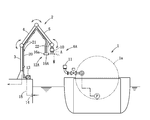
- FIG. 1 is a configuration diagram of an emergency detachment system for liquefied hydrogen according to Embodiment 1.
- FIG. It is a block diagram of the emergency detachment system for liquefied hydrogen concerning Example 2.
- FIG. 1 is a configuration diagram of an emergency detachment system for liquefied hydrogen according to Embodiment 1.
- FIG. It is a block diagram of the emergency detachment system for liquefied hydrogen concerning Example 2.
- the liquefied hydrogen is unloaded from the liquefied hydrogen tank 1a of the liquefied hydrogen carrier 1 to the liquefied hydrogen tank (not shown) on the land, and vice versa.
- a loading arm 2 for liquefied hydrogen is equipped on land.
- the liquefied hydrogen loading arm 2 includes a vacuum heat insulating double pipe inside, and is connected to an onshore liquefied hydrogen tank via the vacuum heat insulating double pipe.
- the loading arm 2 includes an outer riser 3, an inboard arm 4, an outboard arm 5, and an emergency detachment system 6, in which a liquefied hydrogen passage having a vacuum heat insulation double structure is formed.
- the joint 7 for example, the female side of the bayonet joint
- the liquefied hydrogen is transferred after connecting to the joint portion 9 (for example, the male side of the bayonet joint).
- the loading arm 2 When the loading arm 2 is connected to the manifold 8, in an emergency when the weather deteriorates and the liquefied hydrogen carrier 1 shakes violently, a tsunami occurs, or an earthquake occurs and the loading arm 2 shakes violently The loading arm 2 may be damaged.
- the liquefied hydrogen loading arm 2 is equipped with an emergency detachment system 6.
- the emergency departure system 6 includes a land-side first emergency cutoff valve unit 10 and a ship-side second emergency cutoff valve unit 11 detachably connected to the first emergency cutoff valve unit 10 for normal use. In the state, these first and second emergency shut-off valve units 10 and 11 are detachably connected by a connecting device (not shown).
- the emergency release system 6 is activated, the connection by the connecting device is released, and the first emergency shut-off valve unit 10 on the loading arm 2 side is separated from the second emergency shut-off valve unit 11.
- a water curtain forming device 12 for forming the water curtain W is provided on land.
- the water curtain forming apparatus 12 includes a pump 13 that sucks seawater from the sea, and a water curtain forming nozzle 16 that forms the water curtain W with pressurized water supplied from the pump 13.
- the pump 13 is installed on land near the outer riser 3 of the loading arm 2 and sucks seawater from the seawater suction port 14 through the suction pipe 15.
- the water curtain forming nozzle 16 is installed on the side wall of the quay near the pump 13 so as to be at a predetermined height from the sea surface, and pressurized water from the pump 13 is supplied to the water curtain forming nozzle 16 through the discharge pipe 17. Is done.
- the nozzle 16 has a flat rectangular spout that is elongated in the horizontal direction, and has a fan-shaped water curtain W having an opening angle of about 30 to 45 ° in a plan view extending in the space below the first emergency shut-off valve unit 10. Then, a water curtain W extending from the quay, for example, by about 8 m is formed.
- a water curtain W extending from the quay, for example, by about 8 m is formed.
- the water curtain is deployed in a horizontal direction between the first emergency shut-off valve unit 10 and the sea surface S.
- the water curtain W blocks the water and the heat of the water curtain W Since it evaporates, it is possible to reliably prevent the liquefied air droplet A from reaching the sea surface.
- the water curtain forming apparatus 12 includes the pump 13 for sucking seawater from the sea and the water curtain forming nozzle 16, the water curtain forming apparatus 12 having a simple configuration can be realized.
- the emergency shutoff system 6A for the loading arm for liquefied hydrogen according to the second embodiment will be described with reference to FIG.
- the same components as those in the first embodiment are denoted by the same reference numerals, description thereof is omitted, and only different configurations will be described.
- the water curtain forming device 12A includes a pump 13 for sucking seawater from the sea, a flexible water supply hose 20 for supplying pressurized water supplied from the pump 13 along the loading arm 2, and pressurized water from the water supply hose 20. And a water curtain forming nozzle 16 ⁇ / b> A for forming the water curtain W in a region near the lower portion of the first emergency shutoff valve unit 10.
- the water supply hose 20 extends along the outer riser 3, the inboard arm 4, and the outboard arm 5, and is fixed to the outer riser 3, the inboard arm 4, and the outboard arm 5 with a plurality of fasteners 21. .
- the case member 16a of the water curtain forming nozzle 16A is fixed to the tip of the support arm 22 extending from the vicinity of the tip of the outboard arm 5.
- the tip of the water supply hose 20 is connected to a water supply passage in the case member 16a and connected to the nozzle 16A.
- the water curtain forming nozzle 16 ⁇ / b> A is a fan-shaped water curtain W having an opening angle of, for example, about 30 in a plan view extending in the vicinity of the lower portion of the first emergency shut-off valve unit 10, and forms a water curtain W extending, for example, about 2 m. .
- the actions and effects of the water curtain forming device 12A are substantially the same as those of the first embodiment. However, in order to form the water curtain W in the region near the lower part of the first emergency shutoff valve unit 10, if a small water curtain W is formed, Therefore, the pump 13 and the water supply hose 20 can be downsized.
- the installation height position of the water curtain nozzle 16 according to the first embodiment may be set near the sea surface, and the water curtain W may be formed near or on the sea surface.
- the water curtain forming devices 12 and 12A may be configured to form the water curtain W by receiving the supply of pressurized water from a land digestion facility.
- the pump 13 can be omitted, which is advantageous in terms of equipment costs.
Landscapes
- Chemical & Material Sciences (AREA)
- Engineering & Computer Science (AREA)
- Combustion & Propulsion (AREA)
- Mechanical Engineering (AREA)
- Ocean & Marine Engineering (AREA)
- Filling Or Discharging Of Gas Storage Vessels (AREA)
- Loading And Unloading Of Fuel Tanks Or Ships (AREA)
Abstract
液化水素用ローディングアーム(2)に装備される緊急離脱システム(6)において、緊急離脱システム(6)は、陸側の第1緊急遮断弁ユニット(10)と、この第1緊急遮断弁ユニット(10)に分離可能に接続された船側の第2緊急遮断弁ユニット(11)とを備え、緊急離脱時に第1,第2緊急遮断弁ユニット(10,11)が分離状態になったとき、第1緊急遮断弁ユニット(10)と海面との間に水平方向に展開するウォータカーテン(W)を形成するウォータカーテン形成装置(12)を設けた。
Description
本発明は、液化水素用ローディングアームに装備される液化水素用緊急離脱システムに関するものである。
LNG運搬船と陸上のLNGタンクとの間でLNGを移送する場合、陸上側のローディングアームをLNG運搬船のLNG配管のマニホールドに接続して、LNGのローディングやアンローディングを行う(特許文献1、特許文献2)。このローディングやアンローディング中に強風や津波や地震等によりローディングアームが破損するのを防止する為に、ローディングアームには緊急離脱システムが装備されている。
前記緊急離脱システムは、陸側の緊急遮断弁ユニットと、この陸側の緊急遮断弁ユニットに接続された船側の緊急遮断弁ユニットと、これらを分離可能に連結する連結機構とを有する。他方、液化水素用ローディングアームの液化水素用輸送管は、真空断熱構造の二重管であり、緊急離脱システムの緊急遮断弁ユニットも真空断熱構造の二重構造に構成される。
LNGの液化温度は-161℃、酸素の液化温度は-183℃であるため、LNG用ローディングアームの緊急離脱システムが作動しても、分離した緊急遮断弁の接続開口部に液化空気が発生することはない。しかし、水素の液化温度は-253℃で酸素の液化温度よりも低温であるため、液化水素用ローディングアームの緊急離脱システムが作動した場合、ローディングアームの先端の陸側緊急遮断弁ユニットの接続開口部に液化空気が形成され、その液化空気が海面に滴下する。海面上に液化空気(酸素)と反応する物質(例えば、油滴等)がある可能性があるため、液化空気の海面への落下を防止する必要がある。
本発明の目的は、陸側緊急遮断弁ユニットから滴下する液化空気をウォータカーテンで遮断し蒸発させるようにした液化水素用緊急離脱システムを提供することである。
本発明の一態様に係る液化水素用緊急離脱システムは、液化水素用ローディングアームに装備される緊急離脱システムにおいて、前記緊急離脱システムは、陸側の第1緊急遮断弁ユニットと、この第1緊急遮断弁ユニットに分離可能に接続された船側の第2緊急遮断弁ユニットとを備え、緊急離脱時に第1,第2緊急遮断弁ユニットが分離状態になったとき、第1緊急遮断弁ユニットと海面との間に水平方向に展開するウォータカーテンを形成するウォータカーテン形成装置を設けたことを特徴としている。
この構成によれば、緊急離脱時に第1,第2緊急遮断弁ユニットが分離状態になったとき、第1緊急遮断弁ユニットと海面との間に水平方向に展開するウォータカーテンを形成するウォータカーテン形成装置を設けるため、第1緊急遮断弁ユニットの接続開口部に液化空気が発生してその液化空気が下方へ滴下すると、ウォータカーテンに遮断され、ウォータカーテンの熱で蒸発してしまうため、液化空気が海面に到達することを確実に防止することができる。
上記の液化水素用緊急離脱システムにおいて、前記ウォータカーテン形成装置は、海中から海水を吸入するポンプと、このポンプから供給される加圧水で前記ウォータカーテンを形成するウォータカーテン形成ノズルとを備えていてもよい。
この構成によれば、ウォータカーテン形成装置が、海中から海水を吸入するポンプと、ウォータカーテン形成ノズルを備えているため、簡単な構成のウォータカーテン形成装置を実現できる。
上記の液化水素用緊急離脱システムにおいて、前記ウォータカーテン形成装置は、海中から海水を吸入するポンプと、このポンプから供給される加圧水を前記ローディングアームに沿って供給する給水ホースと、この給水ホースから加圧水を受けて第1緊急遮断弁ユニットの下方近傍領域に前記ウォータカーテンを形成するウォータカーテン形成ノズルとを備えていてもよい。
この構成によれば、第1緊急遮断弁ユニットの下方近傍領域にウォータカーテンを形成するため、小型のウォータカーテンを形成すればよいため、ポンプや給水ホースの小型化を図ることができる。
上記の液化水素用緊急離脱システムにおいて、前記ウォータカーテン形成装置は、陸上の消化設備から加圧水の供給を受けて前記ウォータカーテンを形成してもよい。
この構成によれば、前記ウォータカーテン形成装置は、陸上の消化設備から加圧水の供給を受けて前記ウォータカーテンを形成する構成としたので、ポンプを省略可能で、設備費の面で有利になる。
本発明によれば、陸側緊急遮断弁ユニットから滴下する液化空気をウォータカーテンで遮断し蒸発させるようにした液化水素用緊急離脱システムを提供することができる。
本発明を実施するための形態について実施例に基づいて説明する。
図1に示すように、液化水素運搬船1の液化水素タンク1aから陸上の液化水素タンク(図示略)に液化水素をアンローディングしたり、その反対に陸上の液化水素タンクから液化水素運搬船1に液化水素をローディングするために、液化水素用ローディングアーム2が陸上に装備されている。この液化水素用ローディングアーム2は、その内部に真空断熱二重管を備えており、この真空断熱二重管を介して陸上の液化水素タンクに接続されている。
前記ローディングアーム2は、アウタライザ3と、インボードアーム4と、アウトボードアーム5と、緊急離脱システム6を備え、これらの内部に真空断熱二重構造の液化水素通路が形成されている。
このローディングアーム2を介して液化水素のローディングやアンローディングを行う場合、ローディングアーム2の先端の継手部7(例えば、バイヨネット継手の雌側)を液化水素運搬船1上の液化水素配管のマニホールド8の継手部9(例えば、バイヨネット継手の雄側)に接続してから液化水素の移送を行う。
このローディングアーム2を介して液化水素のローディングやアンローディングを行う場合、ローディングアーム2の先端の継手部7(例えば、バイヨネット継手の雌側)を液化水素運搬船1上の液化水素配管のマニホールド8の継手部9(例えば、バイヨネット継手の雄側)に接続してから液化水素の移送を行う。
ローディングアーム2をマニホールド8に接続した状態のとき、天候が悪化して液化水素運搬船1が激しく動揺したり、津波が発生したり、地震が発生してローディングアーム2が激しく動揺したりする緊急時に、ローディングアーム2が破損する虞がある。そこで、この液化水素用ローディングアーム2には緊急離脱システム6が装備されている。
前記緊急離脱システム6は、陸側の第1緊急遮断弁ユニット10と、この第1緊急遮断弁ユニット10に分離可能に接続された船側の第2緊急遮断弁ユニット11とを備え、通常の使用状態においては、これら第1,第2緊急遮断弁ユニット10,11は連結装置(図示略)により分離可能に連結されている。
前記のような緊急時には、緊急離脱システム6が作動し、連結装置による連結が解除されて、ローディングアーム2側の第1緊急遮断弁ユニット10が第2緊急遮断弁ユニット11から分離される。
図2に示すように、上記の緊急離脱時に第1,第2緊急遮断弁ユニット10,11が分離状態になったとき、第1緊急遮断弁ユニット10と海面との間に水平方向に展開するウォータカーテンWを形成するウォータカーテン形成装置12が陸上に設けられている。
このウォータカーテン形成装置12は、海中から海水を吸入するポンプ13と、このポンプ13から供給される加圧水で前記ウォータカーテンWを形成するウォータカーテン形成ノズル16とを備えている。
このウォータカーテン形成装置12は、海中から海水を吸入するポンプ13と、このポンプ13から供給される加圧水で前記ウォータカーテンWを形成するウォータカーテン形成ノズル16とを備えている。
ポンプ13は、ローディングアーム2のアウタライザ3の付近の陸上に設置され、海水吸入口14から吸入管15を介して海水を吸入する。
前記ウォータカーテン形成ノズル16は、ポンプ13の付近の岸壁の側壁部に海面から所定高さ位置となるように設置され、ポンプ13からの加圧水が吐出管17を介してウォータカーテン形成ノズル16に供給される。
前記ウォータカーテン形成ノズル16は、ポンプ13の付近の岸壁の側壁部に海面から所定高さ位置となるように設置され、ポンプ13からの加圧水が吐出管17を介してウォータカーテン形成ノズル16に供給される。
ノズル16は、水平方向に細長い偏平な矩形状の噴出口を有し、第1緊急遮断弁ユニット10の下方空間に広がるような平面視にて開角30~45°程度の扇形のウォータカーテンWであって岸壁から例えば8m程度延びるウォータカーテンWを形成する。
第1緊急遮断弁ユニット10の接続開口部に発生した液化空気の液滴Aが下方へ落下していくと、ウォータカーテンWにトラップされ、ウォータカーテンWの熱により瞬時に蒸発して水素ガスは大気中へ拡散するように構成してある。
第1緊急遮断弁ユニット10の接続開口部に発生した液化空気の液滴Aが下方へ落下していくと、ウォータカーテンWにトラップされ、ウォータカーテンWの熱により瞬時に蒸発して水素ガスは大気中へ拡散するように構成してある。
以上説明した液化水素用緊急遮断システム6の作用、効果について説明する。
緊急離脱時に第1,第2緊急遮断弁ユニット10,11が分離状態になったとき、ウォータカーテン形成装置12が第1緊急遮断弁ユニット10と海面Sとの間に水平方向に展開するウォータカーテンWを形成するため、第1緊急遮断弁ユニット10の接続開口部に液化空気が発生してその液化空気の液滴Aが下方へ滴下すると、ウォータカーテンWで遮断され、ウォータカーテンWの熱で蒸発してしまうため、液化空気の液滴Aが海面に到達することを確実に防止することができる。
緊急離脱時に第1,第2緊急遮断弁ユニット10,11が分離状態になったとき、ウォータカーテン形成装置12が第1緊急遮断弁ユニット10と海面Sとの間に水平方向に展開するウォータカーテンWを形成するため、第1緊急遮断弁ユニット10の接続開口部に液化空気が発生してその液化空気の液滴Aが下方へ滴下すると、ウォータカーテンWで遮断され、ウォータカーテンWの熱で蒸発してしまうため、液化空気の液滴Aが海面に到達することを確実に防止することができる。
ウォータカーテン形成装置12が、海中から海水を吸入するポンプ13と、ウォータカーテン形成ノズル16を備えているため、簡単な構成のウォータカーテン形成装置12を実現できる。
実施例2の液化水素用ローディングアームの緊急遮断システム6Aについて図3に基づいて説明する。但し、実施例1と同じのものに同じ符号を付して説明を省略し、異なる構成についてのみ説明する。
前記ウォータカーテン形成装置12Aは、海中から海水を吸入するポンプ13と、このポンプ13から供給される加圧水をローディングアーム2に沿って供給する可撓性の給水ホース20と、この給水ホース20から加圧水を受けて第1緊急遮断弁ユニット10の下方近傍領域に前記ウォータカーテンWを形成するウォータカーテン形成ノズル16Aとを備えている。
前記給水ホース20は、アウタライザ3と、インボードアーム4と、アウトボードアーム5に沿って延び、複数の留め具21でアウタライザ3と、インボードアーム4と、アウトボードアーム5に固定されている。
ウォータカーテン形成ノズル16Aのケース部材16aは、アウトボードアーム5の先端付近から延ばした支持アーム22の先端に固定されている。給水ホース20の先端がケース部材16a内の給水通路であってノズル16Aに接続された給水通路に接続されている。
ウォータカーテン形成ノズル16Aのケース部材16aは、アウトボードアーム5の先端付近から延ばした支持アーム22の先端に固定されている。給水ホース20の先端がケース部材16a内の給水通路であってノズル16Aに接続された給水通路に接続されている。
ウォータカーテン形成ノズル16Aは、第1緊急遮断弁ユニット10の下方近傍領域に広がるような平面視にて例えば開角30程度の扇形のウォータカーテンWであって例えば2m程度延びるウォータカーテンWを形成する。このウォータカーテン形成装置12Aによる作用、効果は実施例1とほぼ同様であるが、第1緊急遮断弁ユニット10の下方近傍領域にウォータカーテンWを形成するため、小型のウォータカーテンWを形成すればよいため、ポンプ13や給水ホース20の小型化を図ることができる。
前記実施例を部分的に変更する例について説明する。
1)実施例1のウォータカーテンノズル16の設置高さ位置を海面近傍位置とし、海面の近傍又は海面にウォータカーテンWを形成するようにしてもよい。
1)実施例1のウォータカーテンノズル16の設置高さ位置を海面近傍位置とし、海面の近傍又は海面にウォータカーテンWを形成するようにしてもよい。
2)ウォータカーテン形成装置12,12Aは、陸上の消化設備から加圧水の供給を受けて前記ウォータカーテンWを形成するように構成してもよい。この場合、ポンプ13を省略可能で、設備費の面で有利になる。
3)その他、当業者ならば本発明の趣旨を逸脱することなく、前記実施例に種々の変更を付加して実施可能であり、本発明はそのような種々の変更形態を包含するものである。
2 液化水素用ローディングアーム
6,6A 緊急離脱システム
10,11 第1,第2緊急遮断弁ユニット
12,12A ウォータカーテン形成装置
13 ポンプ
16,16A ウォータカーテン形成ノズル
20 給水ホース
6,6A 緊急離脱システム
10,11 第1,第2緊急遮断弁ユニット
12,12A ウォータカーテン形成装置
13 ポンプ
16,16A ウォータカーテン形成ノズル
20 給水ホース
Claims (4)
- 液化水素用ローディングアームに装備される緊急離脱システムにおいて、
前記緊急離脱システムは、陸側の第1緊急遮断弁ユニットと、この第1緊急遮断弁ユニットに分離可能に接続された船側の第2緊急遮断弁ユニットとを備え、
緊急離脱時に第1,第2緊急遮断弁ユニットが分離状態になったとき、第1緊急遮断弁ユニットと海面との間に水平方向に展開するウォータカーテンを形成するウォータカーテン形成装置を設けたことを特徴とする液化水素用緊急離脱システム。 - 前記ウォータカーテン形成装置は、海中から海水を吸入するポンプと、このポンプから供給される加圧水で前記ウォータカーテンを形成するウォータカーテン形成ノズルとを備えたことを特徴とする請求項1に記載の液化水素用緊急離脱システム。
- 前記ウォータカーテン形成装置は、海中から海水を吸入するポンプと、このポンプから供給される加圧水を前記ローディングアームに沿って供給する給水ホースと、
この給水ホースから加圧水を受けて第1緊急遮断弁ユニットの下方近傍領域に前記ウォータカーテンを形成するウォータカーテン形成ノズルとを備えたことを特徴とする請求項1に記載の液化水素用緊急離脱システム。 - 前記ウォータカーテン形成装置は、陸上の消化設備から加圧水の供給を受けて前記ウォータカーテンを形成することを特徴とする請求項1に記載の液化水素用緊急離脱システム。
Applications Claiming Priority (2)
| Application Number | Priority Date | Filing Date | Title |
|---|---|---|---|
| JP2015-139821 | 2015-07-13 | ||
| JP2015139821A JP2017019540A (ja) | 2015-07-13 | 2015-07-13 | 液化水素用緊急離脱システム |
Publications (1)
| Publication Number | Publication Date |
|---|---|
| WO2017010081A1 true WO2017010081A1 (ja) | 2017-01-19 |
Family
ID=57757412
Family Applications (1)
| Application Number | Title | Priority Date | Filing Date |
|---|---|---|---|
| PCT/JP2016/003283 Ceased WO2017010081A1 (ja) | 2015-07-13 | 2016-07-11 | 液体水素用緊急離脱システム |
Country Status (2)
| Country | Link |
|---|---|
| JP (1) | JP2017019540A (ja) |
| WO (1) | WO2017010081A1 (ja) |
Families Citing this family (1)
| Publication number | Priority date | Publication date | Assignee | Title |
|---|---|---|---|---|
| CN111664354B (zh) * | 2020-05-09 | 2021-10-08 | 中国船舶重工集团公司第七一六研究所 | 一种lng大口径岸基智能装卸系统 |
Citations (1)
| Publication number | Priority date | Publication date | Assignee | Title |
|---|---|---|---|---|
| JP2012524002A (ja) * | 2009-04-17 | 2012-10-11 | エクセラレート・エナジー・リミテッド・パートナーシップ | 波止場でのlngの船間移送 |
-
2015
- 2015-07-13 JP JP2015139821A patent/JP2017019540A/ja active Pending
-
2016
- 2016-07-11 WO PCT/JP2016/003283 patent/WO2017010081A1/ja not_active Ceased
Patent Citations (1)
| Publication number | Priority date | Publication date | Assignee | Title |
|---|---|---|---|---|
| JP2012524002A (ja) * | 2009-04-17 | 2012-10-11 | エクセラレート・エナジー・リミテッド・パートナーシップ | 波止場でのlngの船間移送 |
Also Published As
| Publication number | Publication date |
|---|---|
| JP2017019540A (ja) | 2017-01-26 |
Similar Documents
| Publication | Publication Date | Title |
|---|---|---|
| KR101722792B1 (ko) | 부두에서 선박과 선박의 lng 이송 | |
| JP5879360B2 (ja) | 浮体式lngプラント | |
| US9580153B2 (en) | Retractable LNG cargo transfer bow manifold for tandem marine cargo transfers | |
| AU2013384886B2 (en) | A dust suppression system for loading ship holds | |
| JP2024528952A (ja) | アンモニア燃料輸送・補給船 | |
| MY166390A (en) | Device for transferring a liquid to a ship | |
| CN106715997A (zh) | 液化氢输送系统 | |
| CN106062461A (zh) | 冷箱设备和冷箱系统 | |
| JP2017019540A (ja) | 液化水素用緊急離脱システム | |
| US20140116318A1 (en) | Submarine | |
| RU2689894C2 (ru) | Способ и система для перекачки груза текучей среды в открытом море | |
| KR20140089211A (ko) | 선박용 워터 밸러스트 가압 시스템 | |
| AU2015246632B2 (en) | A dust suppression system and apparatus | |
| KR20120001494A (ko) | 흡입관을 가지는 터릿 타입 부유식 해상 구조물 | |
| JP4818648B2 (ja) | 非常用消火ポンプへの給水システム | |
| JP6404067B2 (ja) | 液化水素移送システム | |
| EP3012185A1 (en) | Tug/bunker barge combination | |
| KR20120005093A (ko) | 노즐타입 워터커튼장치를 구비한 선박 | |
| KR20170050382A (ko) | 해양 유체 오프로딩 장치 | |
| JP7661365B2 (ja) | 運搬船への流体炭化水素貨物の積み込みを支援する支援船、並びに、関連するシステム及び方法 | |
| KR20120037685A (ko) | 액화이산화탄소를 이용한 선박 밸러스팅시스템 | |
| CN223887268U (zh) | 一种自卸船低压消防装置 | |
| KR100929709B1 (ko) | 부유식 천연가스 저장선의 액화 천연가스 이송 시스템 | |
| KR20150021300A (ko) | 주소화설비실 및 이를 가지는 lng fpso | |
| KR101732602B1 (ko) | Lng 주유 및 배출과 하역기능을 겸하는 lng 선박용 하이브리드 언로딩 장치 |
Legal Events
| Date | Code | Title | Description |
|---|---|---|---|
| 121 | Ep: the epo has been informed by wipo that ep was designated in this application |
Ref document number: 16824066 Country of ref document: EP Kind code of ref document: A1 |
|
| NENP | Non-entry into the national phase |
Ref country code: DE |
|
| 122 | Ep: pct application non-entry in european phase |
Ref document number: 16824066 Country of ref document: EP Kind code of ref document: A1 |