WO2017007012A1 - Method for manufacturing fiber-reinforced composite material, and fiber-reinforced composite material - Google Patents
Method for manufacturing fiber-reinforced composite material, and fiber-reinforced composite material Download PDFInfo
- Publication number
- WO2017007012A1 WO2017007012A1 PCT/JP2016/070250 JP2016070250W WO2017007012A1 WO 2017007012 A1 WO2017007012 A1 WO 2017007012A1 JP 2016070250 W JP2016070250 W JP 2016070250W WO 2017007012 A1 WO2017007012 A1 WO 2017007012A1
- Authority
- WO
- WIPO (PCT)
- Prior art keywords
- fiber
- composite material
- stack
- reinforced composite
- prepreg
- Prior art date
Links
- 239000000463 material Substances 0.000 title claims abstract description 171
- 239000003733 fiber-reinforced composite Substances 0.000 title claims abstract description 163
- 238000004519 manufacturing process Methods 0.000 title claims abstract description 88
- 238000000034 method Methods 0.000 title claims abstract description 60
- 229920005989 resin Polymers 0.000 claims abstract description 145
- 239000011347 resin Substances 0.000 claims abstract description 145
- 239000000835 fiber Substances 0.000 claims abstract description 137
- 239000012783 reinforcing fiber Substances 0.000 claims abstract description 90
- 238000000465 moulding Methods 0.000 claims abstract description 67
- 239000011342 resin composition Substances 0.000 claims abstract description 44
- 239000011159 matrix material Substances 0.000 claims abstract description 30
- 229920001971 elastomer Polymers 0.000 claims description 8
- 239000005060 rubber Substances 0.000 claims description 8
- 239000000203 mixture Substances 0.000 claims description 7
- 239000011208 reinforced composite material Substances 0.000 claims description 3
- 230000007547 defect Effects 0.000 abstract description 15
- 230000037303 wrinkles Effects 0.000 description 38
- 238000010438 heat treatment Methods 0.000 description 15
- 238000000748 compression moulding Methods 0.000 description 12
- 229920000049 Carbon (fiber) Polymers 0.000 description 10
- 239000004917 carbon fiber Substances 0.000 description 10
- 239000003822 epoxy resin Substances 0.000 description 10
- 229920000647 polyepoxide Polymers 0.000 description 10
- 229920000297 Rayon Polymers 0.000 description 7
- 239000004744 fabric Substances 0.000 description 7
- 238000003475 lamination Methods 0.000 description 7
- 238000002360 preparation method Methods 0.000 description 7
- PPBRXRYQALVLMV-UHFFFAOYSA-N Styrene Chemical compound C=CC1=CC=CC=C1 PPBRXRYQALVLMV-UHFFFAOYSA-N 0.000 description 6
- 238000011156 evaluation Methods 0.000 description 6
- VNWKTOKETHGBQD-UHFFFAOYSA-N methane Chemical compound C VNWKTOKETHGBQD-UHFFFAOYSA-N 0.000 description 6
- 239000004800 polyvinyl chloride Substances 0.000 description 6
- 229920000915 polyvinyl chloride Polymers 0.000 description 6
- 230000006835 compression Effects 0.000 description 5
- 238000007906 compression Methods 0.000 description 5
- 229910052751 metal Inorganic materials 0.000 description 5
- 239000002184 metal Substances 0.000 description 5
- 239000000126 substance Substances 0.000 description 5
- 229920001187 thermosetting polymer Polymers 0.000 description 5
- 239000002023 wood Substances 0.000 description 5
- 239000003677 Sheet moulding compound Substances 0.000 description 4
- 230000002950 deficient Effects 0.000 description 4
- 238000010030 laminating Methods 0.000 description 4
- 229920001567 vinyl ester resin Polymers 0.000 description 4
- 239000004925 Acrylic resin Substances 0.000 description 3
- 229920000178 Acrylic resin Polymers 0.000 description 3
- NLHHRLWOUZZQLW-UHFFFAOYSA-N Acrylonitrile Chemical compound C=CC#N NLHHRLWOUZZQLW-UHFFFAOYSA-N 0.000 description 3
- 230000000295 complement effect Effects 0.000 description 3
- 239000002131 composite material Substances 0.000 description 3
- 238000005520 cutting process Methods 0.000 description 3
- 230000000694 effects Effects 0.000 description 3
- 239000005011 phenolic resin Substances 0.000 description 3
- 238000007493 shaping process Methods 0.000 description 3
- 229920002379 silicone rubber Polymers 0.000 description 3
- 229920006337 unsaturated polyester resin Polymers 0.000 description 3
- RNFJDJUURJAICM-UHFFFAOYSA-N 2,2,4,4,6,6-hexaphenoxy-1,3,5-triaza-2$l^{5},4$l^{5},6$l^{5}-triphosphacyclohexa-1,3,5-triene Chemical compound N=1P(OC=2C=CC=CC=2)(OC=2C=CC=CC=2)=NP(OC=2C=CC=CC=2)(OC=2C=CC=CC=2)=NP=1(OC=1C=CC=CC=1)OC1=CC=CC=C1 RNFJDJUURJAICM-UHFFFAOYSA-N 0.000 description 2
- CMLFRMDBDNHMRA-UHFFFAOYSA-N 2h-1,2-benzoxazine Chemical compound C1=CC=C2C=CNOC2=C1 CMLFRMDBDNHMRA-UHFFFAOYSA-N 0.000 description 2
- IJGRMHOSHXDMSA-UHFFFAOYSA-N Atomic nitrogen Chemical class N#N IJGRMHOSHXDMSA-UHFFFAOYSA-N 0.000 description 2
- ZOXJGFHDIHLPTG-UHFFFAOYSA-N Boron Chemical compound [B] ZOXJGFHDIHLPTG-UHFFFAOYSA-N 0.000 description 2
- KAKZBPTYRLMSJV-UHFFFAOYSA-N Butadiene Chemical compound C=CC=C KAKZBPTYRLMSJV-UHFFFAOYSA-N 0.000 description 2
- 244000043261 Hevea brasiliensis Species 0.000 description 2
- XEEYBQQBJWHFJM-UHFFFAOYSA-N Iron Chemical compound [Fe] XEEYBQQBJWHFJM-UHFFFAOYSA-N 0.000 description 2
- PNEYBMLMFCGWSK-UHFFFAOYSA-N aluminium oxide Inorganic materials [O-2].[O-2].[O-2].[Al+3].[Al+3] PNEYBMLMFCGWSK-UHFFFAOYSA-N 0.000 description 2
- 229920006231 aramid fiber Polymers 0.000 description 2
- 229910052796 boron Inorganic materials 0.000 description 2
- 150000001875 compounds Chemical class 0.000 description 2
- 238000001816 cooling Methods 0.000 description 2
- 239000003063 flame retardant Substances 0.000 description 2
- 239000003365 glass fiber Substances 0.000 description 2
- 239000012784 inorganic fiber Substances 0.000 description 2
- 229920003052 natural elastomer Polymers 0.000 description 2
- 229920001194 natural rubber Polymers 0.000 description 2
- 229920001778 nylon Polymers 0.000 description 2
- 229920000728 polyester Polymers 0.000 description 2
- 238000003825 pressing Methods 0.000 description 2
- 238000004088 simulation Methods 0.000 description 2
- 238000003892 spreading Methods 0.000 description 2
- 229920005992 thermoplastic resin Polymers 0.000 description 2
- 238000009941 weaving Methods 0.000 description 2
- 239000002759 woven fabric Substances 0.000 description 2
- NIXOWILDQLNWCW-UHFFFAOYSA-M Acrylate Chemical compound [O-]C(=O)C=C NIXOWILDQLNWCW-UHFFFAOYSA-M 0.000 description 1
- WKBOTKDWSSQWDR-UHFFFAOYSA-N Bromine atom Chemical class [Br] WKBOTKDWSSQWDR-UHFFFAOYSA-N 0.000 description 1
- OKTJSMMVPCPJKN-UHFFFAOYSA-N Carbon Chemical compound [C] OKTJSMMVPCPJKN-UHFFFAOYSA-N 0.000 description 1
- JOYRKODLDBILNP-UHFFFAOYSA-N Ethyl urethane Chemical compound CCOC(N)=O JOYRKODLDBILNP-UHFFFAOYSA-N 0.000 description 1
- PEEHTFAAVSWFBL-UHFFFAOYSA-N Maleimide Chemical compound O=C1NC(=O)C=C1 PEEHTFAAVSWFBL-UHFFFAOYSA-N 0.000 description 1
- 229920000459 Nitrile rubber Polymers 0.000 description 1
- OAICVXFJPJFONN-UHFFFAOYSA-N Phosphorus Chemical class [P] OAICVXFJPJFONN-UHFFFAOYSA-N 0.000 description 1
- 229910052581 Si3N4 Inorganic materials 0.000 description 1
- 229920000690 Tyvek Polymers 0.000 description 1
- 229920000122 acrylonitrile butadiene styrene Polymers 0.000 description 1
- -1 amine compounds Chemical class 0.000 description 1
- 239000004760 aramid Substances 0.000 description 1
- 238000005452 bending Methods 0.000 description 1
- 230000015572 biosynthetic process Effects 0.000 description 1
- QHIWVLPBUQWDMQ-UHFFFAOYSA-N butyl prop-2-enoate;methyl 2-methylprop-2-enoate;prop-2-enoic acid Chemical compound OC(=O)C=C.COC(=O)C(C)=C.CCCCOC(=O)C=C QHIWVLPBUQWDMQ-UHFFFAOYSA-N 0.000 description 1
- 230000003247 decreasing effect Effects 0.000 description 1
- 230000006866 deterioration Effects 0.000 description 1
- 150000001993 dienes Chemical class 0.000 description 1
- 238000005516 engineering process Methods 0.000 description 1
- 150000002148 esters Chemical class 0.000 description 1
- HQQADJVZYDDRJT-UHFFFAOYSA-N ethene;prop-1-ene Chemical group C=C.CC=C HQQADJVZYDDRJT-UHFFFAOYSA-N 0.000 description 1
- 239000010439 graphite Substances 0.000 description 1
- 229910002804 graphite Inorganic materials 0.000 description 1
- 239000010440 gypsum Substances 0.000 description 1
- 229910052602 gypsum Inorganic materials 0.000 description 1
- LNEPOXFFQSENCJ-UHFFFAOYSA-N haloperidol Chemical compound C1CC(O)(C=2C=CC(Cl)=CC=2)CCN1CCCC(=O)C1=CC=C(F)C=C1 LNEPOXFFQSENCJ-UHFFFAOYSA-N 0.000 description 1
- 229910052742 iron Inorganic materials 0.000 description 1
- 229910000000 metal hydroxide Inorganic materials 0.000 description 1
- 150000004692 metal hydroxides Chemical class 0.000 description 1
- 150000002739 metals Chemical class 0.000 description 1
- 229910052757 nitrogen Inorganic materials 0.000 description 1
- 229910052698 phosphorus Inorganic materials 0.000 description 1
- 239000011574 phosphorus Substances 0.000 description 1
- 150000003018 phosphorus compounds Chemical class 0.000 description 1
- 239000002985 plastic film Substances 0.000 description 1
- 229920006255 plastic film Polymers 0.000 description 1
- 229920006122 polyamide resin Polymers 0.000 description 1
- 229920001721 polyimide Polymers 0.000 description 1
- 239000009719 polyimide resin Substances 0.000 description 1
- 229920000098 polyolefin Polymers 0.000 description 1
- 229920001296 polysiloxane Chemical class 0.000 description 1
- 230000003014 reinforcing effect Effects 0.000 description 1
- HBMJWWWQQXIZIP-UHFFFAOYSA-N silicon carbide Chemical compound [Si+]#[C-] HBMJWWWQQXIZIP-UHFFFAOYSA-N 0.000 description 1
- 229910010271 silicon carbide Inorganic materials 0.000 description 1
- HQVNEWCFYHHQES-UHFFFAOYSA-N silicon nitride Chemical compound N12[Si]34N5[Si]62N3[Si]51N64 HQVNEWCFYHHQES-UHFFFAOYSA-N 0.000 description 1
- 238000009751 slip forming Methods 0.000 description 1
- 229910001220 stainless steel Inorganic materials 0.000 description 1
- 239000010935 stainless steel Substances 0.000 description 1
- UONOETXJSWQNOL-UHFFFAOYSA-N tungsten carbide Chemical compound [W+]#[C-] UONOETXJSWQNOL-UHFFFAOYSA-N 0.000 description 1
- 238000009849 vacuum degassing Methods 0.000 description 1
Images


Classifications
-
- B—PERFORMING OPERATIONS; TRANSPORTING
- B29—WORKING OF PLASTICS; WORKING OF SUBSTANCES IN A PLASTIC STATE IN GENERAL
- B29C—SHAPING OR JOINING OF PLASTICS; SHAPING OF MATERIAL IN A PLASTIC STATE, NOT OTHERWISE PROVIDED FOR; AFTER-TREATMENT OF THE SHAPED PRODUCTS, e.g. REPAIRING
- B29C70/00—Shaping composites, i.e. plastics material comprising reinforcements, fillers or preformed parts, e.g. inserts
- B29C70/04—Shaping composites, i.e. plastics material comprising reinforcements, fillers or preformed parts, e.g. inserts comprising reinforcements only, e.g. self-reinforcing plastics
- B29C70/06—Fibrous reinforcements only
- B29C70/10—Fibrous reinforcements only characterised by the structure of fibrous reinforcements, e.g. hollow fibres
- B29C70/16—Fibrous reinforcements only characterised by the structure of fibrous reinforcements, e.g. hollow fibres using fibres of substantial or continuous length
- B29C70/22—Fibrous reinforcements only characterised by the structure of fibrous reinforcements, e.g. hollow fibres using fibres of substantial or continuous length oriented in at least two directions forming a two dimensional structure
-
- B—PERFORMING OPERATIONS; TRANSPORTING
- B29—WORKING OF PLASTICS; WORKING OF SUBSTANCES IN A PLASTIC STATE IN GENERAL
- B29C—SHAPING OR JOINING OF PLASTICS; SHAPING OF MATERIAL IN A PLASTIC STATE, NOT OTHERWISE PROVIDED FOR; AFTER-TREATMENT OF THE SHAPED PRODUCTS, e.g. REPAIRING
- B29C70/00—Shaping composites, i.e. plastics material comprising reinforcements, fillers or preformed parts, e.g. inserts
- B29C70/04—Shaping composites, i.e. plastics material comprising reinforcements, fillers or preformed parts, e.g. inserts comprising reinforcements only, e.g. self-reinforcing plastics
- B29C70/06—Fibrous reinforcements only
- B29C70/10—Fibrous reinforcements only characterised by the structure of fibrous reinforcements, e.g. hollow fibres
- B29C70/16—Fibrous reinforcements only characterised by the structure of fibrous reinforcements, e.g. hollow fibres using fibres of substantial or continuous length
- B29C70/20—Fibrous reinforcements only characterised by the structure of fibrous reinforcements, e.g. hollow fibres using fibres of substantial or continuous length oriented in a single direction, e.g. roofing or other parallel fibres
- B29C70/205—Fibrous reinforcements only characterised by the structure of fibrous reinforcements, e.g. hollow fibres using fibres of substantial or continuous length oriented in a single direction, e.g. roofing or other parallel fibres the structure being shaped to form a three-dimensional configuration
- B29C70/207—Fibrous reinforcements only characterised by the structure of fibrous reinforcements, e.g. hollow fibres using fibres of substantial or continuous length oriented in a single direction, e.g. roofing or other parallel fibres the structure being shaped to form a three-dimensional configuration arranged in parallel planes of fibres crossing at substantial angles
-
- B—PERFORMING OPERATIONS; TRANSPORTING
- B29—WORKING OF PLASTICS; WORKING OF SUBSTANCES IN A PLASTIC STATE IN GENERAL
- B29B—PREPARATION OR PRETREATMENT OF THE MATERIAL TO BE SHAPED; MAKING GRANULES OR PREFORMS; RECOVERY OF PLASTICS OR OTHER CONSTITUENTS OF WASTE MATERIAL CONTAINING PLASTICS
- B29B11/00—Making preforms
- B29B11/06—Making preforms by moulding the material
- B29B11/12—Compression moulding
-
- B—PERFORMING OPERATIONS; TRANSPORTING
- B29—WORKING OF PLASTICS; WORKING OF SUBSTANCES IN A PLASTIC STATE IN GENERAL
- B29B—PREPARATION OR PRETREATMENT OF THE MATERIAL TO BE SHAPED; MAKING GRANULES OR PREFORMS; RECOVERY OF PLASTICS OR OTHER CONSTITUENTS OF WASTE MATERIAL CONTAINING PLASTICS
- B29B11/00—Making preforms
- B29B11/14—Making preforms characterised by structure or composition
- B29B11/16—Making preforms characterised by structure or composition comprising fillers or reinforcement
-
- B—PERFORMING OPERATIONS; TRANSPORTING
- B29—WORKING OF PLASTICS; WORKING OF SUBSTANCES IN A PLASTIC STATE IN GENERAL
- B29C—SHAPING OR JOINING OF PLASTICS; SHAPING OF MATERIAL IN A PLASTIC STATE, NOT OTHERWISE PROVIDED FOR; AFTER-TREATMENT OF THE SHAPED PRODUCTS, e.g. REPAIRING
- B29C43/00—Compression moulding, i.e. applying external pressure to flow the moulding material; Apparatus therefor
- B29C43/02—Compression moulding, i.e. applying external pressure to flow the moulding material; Apparatus therefor of articles of definite length, i.e. discrete articles
- B29C43/20—Making multilayered or multicoloured articles
- B29C43/203—Making multilayered articles
-
- B—PERFORMING OPERATIONS; TRANSPORTING
- B29—WORKING OF PLASTICS; WORKING OF SUBSTANCES IN A PLASTIC STATE IN GENERAL
- B29C—SHAPING OR JOINING OF PLASTICS; SHAPING OF MATERIAL IN A PLASTIC STATE, NOT OTHERWISE PROVIDED FOR; AFTER-TREATMENT OF THE SHAPED PRODUCTS, e.g. REPAIRING
- B29C70/00—Shaping composites, i.e. plastics material comprising reinforcements, fillers or preformed parts, e.g. inserts
- B29C70/04—Shaping composites, i.e. plastics material comprising reinforcements, fillers or preformed parts, e.g. inserts comprising reinforcements only, e.g. self-reinforcing plastics
- B29C70/06—Fibrous reinforcements only
- B29C70/08—Fibrous reinforcements only comprising combinations of different forms of fibrous reinforcements incorporated in matrix material, forming one or more layers, and with or without non-reinforced layers
- B29C70/086—Fibrous reinforcements only comprising combinations of different forms of fibrous reinforcements incorporated in matrix material, forming one or more layers, and with or without non-reinforced layers and with one or more layers of pure plastics material, e.g. foam layers
-
- B—PERFORMING OPERATIONS; TRANSPORTING
- B29—WORKING OF PLASTICS; WORKING OF SUBSTANCES IN A PLASTIC STATE IN GENERAL
- B29C—SHAPING OR JOINING OF PLASTICS; SHAPING OF MATERIAL IN A PLASTIC STATE, NOT OTHERWISE PROVIDED FOR; AFTER-TREATMENT OF THE SHAPED PRODUCTS, e.g. REPAIRING
- B29C70/00—Shaping composites, i.e. plastics material comprising reinforcements, fillers or preformed parts, e.g. inserts
- B29C70/04—Shaping composites, i.e. plastics material comprising reinforcements, fillers or preformed parts, e.g. inserts comprising reinforcements only, e.g. self-reinforcing plastics
- B29C70/06—Fibrous reinforcements only
- B29C70/10—Fibrous reinforcements only characterised by the structure of fibrous reinforcements, e.g. hollow fibres
- B29C70/16—Fibrous reinforcements only characterised by the structure of fibrous reinforcements, e.g. hollow fibres using fibres of substantial or continuous length
- B29C70/22—Fibrous reinforcements only characterised by the structure of fibrous reinforcements, e.g. hollow fibres using fibres of substantial or continuous length oriented in at least two directions forming a two dimensional structure
- B29C70/222—Fibrous reinforcements only characterised by the structure of fibrous reinforcements, e.g. hollow fibres using fibres of substantial or continuous length oriented in at least two directions forming a two dimensional structure the structure being shaped to form a three dimensional configuration
-
- B—PERFORMING OPERATIONS; TRANSPORTING
- B29—WORKING OF PLASTICS; WORKING OF SUBSTANCES IN A PLASTIC STATE IN GENERAL
- B29C—SHAPING OR JOINING OF PLASTICS; SHAPING OF MATERIAL IN A PLASTIC STATE, NOT OTHERWISE PROVIDED FOR; AFTER-TREATMENT OF THE SHAPED PRODUCTS, e.g. REPAIRING
- B29C70/00—Shaping composites, i.e. plastics material comprising reinforcements, fillers or preformed parts, e.g. inserts
- B29C70/04—Shaping composites, i.e. plastics material comprising reinforcements, fillers or preformed parts, e.g. inserts comprising reinforcements only, e.g. self-reinforcing plastics
- B29C70/06—Fibrous reinforcements only
- B29C70/10—Fibrous reinforcements only characterised by the structure of fibrous reinforcements, e.g. hollow fibres
- B29C70/16—Fibrous reinforcements only characterised by the structure of fibrous reinforcements, e.g. hollow fibres using fibres of substantial or continuous length
- B29C70/22—Fibrous reinforcements only characterised by the structure of fibrous reinforcements, e.g. hollow fibres using fibres of substantial or continuous length oriented in at least two directions forming a two dimensional structure
- B29C70/228—Fibrous reinforcements only characterised by the structure of fibrous reinforcements, e.g. hollow fibres using fibres of substantial or continuous length oriented in at least two directions forming a two dimensional structure the structure being stacked in parallel layers with fibres of adjacent layers crossing at substantial angles
-
- B—PERFORMING OPERATIONS; TRANSPORTING
- B29—WORKING OF PLASTICS; WORKING OF SUBSTANCES IN A PLASTIC STATE IN GENERAL
- B29C—SHAPING OR JOINING OF PLASTICS; SHAPING OF MATERIAL IN A PLASTIC STATE, NOT OTHERWISE PROVIDED FOR; AFTER-TREATMENT OF THE SHAPED PRODUCTS, e.g. REPAIRING
- B29C70/00—Shaping composites, i.e. plastics material comprising reinforcements, fillers or preformed parts, e.g. inserts
- B29C70/04—Shaping composites, i.e. plastics material comprising reinforcements, fillers or preformed parts, e.g. inserts comprising reinforcements only, e.g. self-reinforcing plastics
- B29C70/28—Shaping operations therefor
- B29C70/30—Shaping by lay-up, i.e. applying fibres, tape or broadsheet on a mould, former or core; Shaping by spray-up, i.e. spraying of fibres on a mould, former or core
-
- B—PERFORMING OPERATIONS; TRANSPORTING
- B29—WORKING OF PLASTICS; WORKING OF SUBSTANCES IN A PLASTIC STATE IN GENERAL
- B29C—SHAPING OR JOINING OF PLASTICS; SHAPING OF MATERIAL IN A PLASTIC STATE, NOT OTHERWISE PROVIDED FOR; AFTER-TREATMENT OF THE SHAPED PRODUCTS, e.g. REPAIRING
- B29C70/00—Shaping composites, i.e. plastics material comprising reinforcements, fillers or preformed parts, e.g. inserts
- B29C70/04—Shaping composites, i.e. plastics material comprising reinforcements, fillers or preformed parts, e.g. inserts comprising reinforcements only, e.g. self-reinforcing plastics
- B29C70/28—Shaping operations therefor
- B29C70/40—Shaping or impregnating by compression not applied
- B29C70/42—Shaping or impregnating by compression not applied for producing articles of definite length, i.e. discrete articles
- B29C70/46—Shaping or impregnating by compression not applied for producing articles of definite length, i.e. discrete articles using matched moulds, e.g. for deforming sheet moulding compounds [SMC] or prepregs
-
- B—PERFORMING OPERATIONS; TRANSPORTING
- B32—LAYERED PRODUCTS
- B32B—LAYERED PRODUCTS, i.e. PRODUCTS BUILT-UP OF STRATA OF FLAT OR NON-FLAT, e.g. CELLULAR OR HONEYCOMB, FORM
- B32B27/00—Layered products comprising a layer of synthetic resin
- B32B27/12—Layered products comprising a layer of synthetic resin next to a fibrous or filamentary layer
-
- B—PERFORMING OPERATIONS; TRANSPORTING
- B32—LAYERED PRODUCTS
- B32B—LAYERED PRODUCTS, i.e. PRODUCTS BUILT-UP OF STRATA OF FLAT OR NON-FLAT, e.g. CELLULAR OR HONEYCOMB, FORM
- B32B5/00—Layered products characterised by the non- homogeneity or physical structure, i.e. comprising a fibrous, filamentary, particulate or foam layer; Layered products characterised by having a layer differing constitutionally or physically in different parts
- B32B5/02—Layered products characterised by the non- homogeneity or physical structure, i.e. comprising a fibrous, filamentary, particulate or foam layer; Layered products characterised by having a layer differing constitutionally or physically in different parts characterised by structural features of a fibrous or filamentary layer
- B32B5/12—Layered products characterised by the non- homogeneity or physical structure, i.e. comprising a fibrous, filamentary, particulate or foam layer; Layered products characterised by having a layer differing constitutionally or physically in different parts characterised by structural features of a fibrous or filamentary layer characterised by the relative arrangement of fibres or filaments of different layers, e.g. the fibres or filaments being parallel or perpendicular to each other
-
- B—PERFORMING OPERATIONS; TRANSPORTING
- B32—LAYERED PRODUCTS
- B32B—LAYERED PRODUCTS, i.e. PRODUCTS BUILT-UP OF STRATA OF FLAT OR NON-FLAT, e.g. CELLULAR OR HONEYCOMB, FORM
- B32B5/00—Layered products characterised by the non- homogeneity or physical structure, i.e. comprising a fibrous, filamentary, particulate or foam layer; Layered products characterised by having a layer differing constitutionally or physically in different parts
- B32B5/22—Layered products characterised by the non- homogeneity or physical structure, i.e. comprising a fibrous, filamentary, particulate or foam layer; Layered products characterised by having a layer differing constitutionally or physically in different parts characterised by the presence of two or more layers which are next to each other and are fibrous, filamentary, formed of particles or foamed
- B32B5/24—Layered products characterised by the non- homogeneity or physical structure, i.e. comprising a fibrous, filamentary, particulate or foam layer; Layered products characterised by having a layer differing constitutionally or physically in different parts characterised by the presence of two or more layers which are next to each other and are fibrous, filamentary, formed of particles or foamed one layer being a fibrous or filamentary layer
- B32B5/26—Layered products characterised by the non- homogeneity or physical structure, i.e. comprising a fibrous, filamentary, particulate or foam layer; Layered products characterised by having a layer differing constitutionally or physically in different parts characterised by the presence of two or more layers which are next to each other and are fibrous, filamentary, formed of particles or foamed one layer being a fibrous or filamentary layer another layer next to it also being fibrous or filamentary
-
- C—CHEMISTRY; METALLURGY
- C08—ORGANIC MACROMOLECULAR COMPOUNDS; THEIR PREPARATION OR CHEMICAL WORKING-UP; COMPOSITIONS BASED THEREON
- C08J—WORKING-UP; GENERAL PROCESSES OF COMPOUNDING; AFTER-TREATMENT NOT COVERED BY SUBCLASSES C08B, C08C, C08F, C08G or C08H
- C08J5/00—Manufacture of articles or shaped materials containing macromolecular substances
- C08J5/24—Impregnating materials with prepolymers which can be polymerised in situ, e.g. manufacture of prepregs
- C08J5/241—Impregnating materials with prepolymers which can be polymerised in situ, e.g. manufacture of prepregs using inorganic fibres
- C08J5/243—Impregnating materials with prepolymers which can be polymerised in situ, e.g. manufacture of prepregs using inorganic fibres using carbon fibres
-
- B—PERFORMING OPERATIONS; TRANSPORTING
- B29—WORKING OF PLASTICS; WORKING OF SUBSTANCES IN A PLASTIC STATE IN GENERAL
- B29K—INDEXING SCHEME ASSOCIATED WITH SUBCLASSES B29B, B29C OR B29D, RELATING TO MOULDING MATERIALS OR TO MATERIALS FOR MOULDS, REINFORCEMENTS, FILLERS OR PREFORMED PARTS, e.g. INSERTS
- B29K2105/00—Condition, form or state of moulded material or of the material to be shaped
- B29K2105/06—Condition, form or state of moulded material or of the material to be shaped containing reinforcements, fillers or inserts
- B29K2105/08—Condition, form or state of moulded material or of the material to be shaped containing reinforcements, fillers or inserts of continuous length, e.g. cords, rovings, mats, fabrics, strands or yarns
- B29K2105/0872—Prepregs
- B29K2105/0881—Prepregs unidirectional
Definitions
- the present invention relates to a method for producing a fiber-reinforced composite material and a fiber-reinforced composite material.
- a sheet-shaped prepreg containing reinforcing fibers and a thermosetting resin, or a stack made of a laminate of the prepreg is heated and pressurized to form a three-dimensional shape, etc.
- a fiber-reinforced composite material molded into a complicated shape is used.
- it is difficult to form at once when a fiber reinforced composite material having a complicated shape such as a three-dimensional curved surface shape, a hemispherical shape, or the like with shear deformation is used.
- a preform is manufactured in which the stack is preformed into an intermediate shape based on the final shape.
- the reinforcing fibers in the stack cannot follow the deformation during molding, and the resulting fiber reinforced composite materials and preforms have fiber meandering and wrinkles, resulting in poor appearance. May be.
- the reinforcing fibers are less likely to follow deformation in a direction in which the reinforcing fibers are not oriented.
- a sheet-like UD prepreg in which reinforcing fibers are aligned in one direction is obtained in a plan view for the purpose of obtaining a fiber-reinforced composite material having excellent isotropic mechanical properties.
- a stack that is laminated in a general pseudo-isotropy in which the fiber direction of each layer is [0 ° / 45 ° / 90 ° / 135 °] is used.
- this stack is molded into a three-dimensional shape having a curved surface, wrinkles are likely to occur in the resulting preform.
- the fiber reinforced composite material obtained by compression molding this preform is likely to cause meandering of the reinforcing fiber, and the appearance and mechanical properties of the fiber reinforced composite material may be greatly deteriorated.
- This problem can be partially solved by forming a stack in which the UD prepreg is laminated so that the fiber direction of each layer is [0 ° / 90 ° / 45 ° / 135 °] instead of the general pseudo-isotropic method. It is improved, but the improvement effect is limited.
- the laminated UD prepreg fiber direction is divided into [0 ° / 90 °] paired portions and [45 ° / 135 °] paired portions, and molding each paired portion, the generation of wrinkles is suppressed.
- it can be formed into a three-dimensional shape having a curved surface. This means that during molding, the [0 ° / 90 °] paired part extends relatively easily in the 45 ° and 135 ° directions, and the [45 ° / 135 °] paired part extends in the 0 ° and 90 ° directions. This is thought to be because it can be stretched.
- this method needs to form a plurality of paired parts, which leads to an increase in working time and cost.
- the present invention is formed into a three-dimensional curved surface shape having a three-dimensional shape, particularly a non-developable curved surface (including a combination of a plurality of flat surfaces) with high productivity while suppressing appearance defects such as fiber meandering and wrinkles.
- the present invention has the following configuration.
- a stack in which a plurality of sheet-like prepregs (X) in which a matrix resin composition is impregnated with a plurality of continuously arranged reinforcing fibers is laminated so that the fiber directions are different from each other is formed into a pair of molds.
- the stack a stack in which a plurality of the prepregs (X) and one or more resin films (Y) made of a resin composition (excluding the prepreg (X)) are stacked is used. , [1] or [2] The manufacturing method of the fiber reinforced composite material.
- the stack includes a prepreg (X) / prepreg (X) / resin film (Y) / prepreg (X) / prepreg (X) laminated unit having a five-layer structure, and the first layer of the prepreg (X) When the fiber direction is set to 0 °, the prepreg (X) of the second layer, the fourth layer, and the fifth layer each have a fiber direction of 15 to 165 °, and a stack having different fiber directions of each layer is used.
- the manufacturing method of the fiber reinforced composite material of description is described.
- the fiber direction of the prepreg (X) of the second layer is 85 to 95 °
- the fiber direction of the prepreg (X) of the fourth layer is 30 to 60 °
- the prepreg of the fifth layer The method for producing a fiber-reinforced composite material according to [4], wherein the fiber direction of X) is 120 to 150 °.
- As the stack a stack including two or more of the stacked units and stacked such that the resin film (Y) is sandwiched between the stacked units adjacent in the thickness direction is used. [4 ] Or the manufacturing method of the fiber reinforced composite material as described in [5].
- the stack includes two stacked units having the same stacked configuration, and the stacked units are stacked so that their stacking order is symmetric in the thickness direction.
- the stack includes a stack including a stacked unit in which a difference in angle between the fiber direction of the fourth layer and the fiber direction of the fifth layer is 90 °, as described in any one of [5] to [7] The manufacturing method of the fiber reinforced composite material of description.
- the pair of molds are composed of a lower mold and an upper mold, and are arranged while tensioning the stretchable sheet so that the stretchable sheet is in partial contact with a portion of the molding surface of the lower mold facing the upper mold.
- the preform is compression-molded again by the pair of molds in a state where the stretchable sheet is not disposed to obtain a fiber-reinforced composite material.
- a fiber reinforced composite material having excellent appearance and mechanical properties.
- appearance defects such as fiber meandering and wrinkles are suppressed, and both excellent appearance and excellent mechanical properties are achieved.
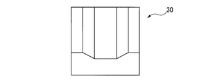
- FIG. 3A It is a side view of the fiber reinforced composite material of FIG. 3A. It is the perspective view which showed an example of the fiber reinforced composite material manufactured with the manufacturing method of this invention. It is the perspective view which showed an example of the shaping
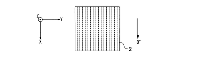
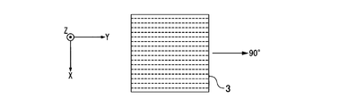
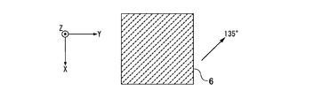
- the fiber direction of the prepreg in the stack is positive in the counterclockwise direction when the stack is viewed from the first layer side.
- the fiber direction of the prepreg is the orientation direction of the reinforcing fiber in the case of a UD prepreg in which the reinforcing fibers are aligned in one direction.
- the orientation direction of the reinforcing fibers of the warp is defined as the fiber direction.
- the reinforcing axis is a symmetrical axis that bisects the prepreg in the sheet plane of the prepreg in a bilaterally symmetrical manner, and the fiber axis direction is the direction of the symmetrical axis.
- the direction of the axis of symmetry where the fiber component is maximum is taken as the fiber direction.
- Method for producing fiber-reinforced composite material In the method for producing a fiber-reinforced composite material of the present invention, a plurality of sheet-like prepregs (X) in which a matrix resin composition is impregnated with a plurality of continuously arranged reinforcing fibers are laminated so that the fiber directions are different.
- This is a method of obtaining a fiber-reinforced composite material by forming the stack thus obtained into a three-dimensional shape using a forming die having a pair of dies.
- the method for producing a fiber-reinforced composite material of the present invention may be a method in which a stack is formed into a fiber-reinforced composite material by a single compression molding.
- the stack is preformed into a preform, and the preform is further compression-molded.
- a method for obtaining a fiber-reinforced composite material may be used. From the viewpoint of easily obtaining a fiber-reinforced composite material such as a three-dimensional curved surface having a curved surface that is not a developable surface while suppressing appearance defects such as fiber meandering and wrinkles, the stack is preformed into a preform, and the preform is further formed. A method of compressing the reform to obtain a fiber reinforced composite material is preferable.
- the stack is formed by laminating a plurality of sheet-like prepregs (X) in which a matrix resin composition is impregnated into a plurality of continuously arranged reinforcing fibers so that the fiber directions are different.
- the stack it is preferable to use a stack in which a plurality of prepregs (X) and one or more resin films (Y) made of a resin composition (excluding the prepreg (X)) are laminated.
- the fiber reinforced composite material in which appearance defects such as wrinkles are suppressed can be manufactured in a shorter time.
- prepreg (X) / prepreg (X) / resin film (Y) / prepreg (X) / prepreg (X) A stack including a laminated unit having a five-layer structure is preferable.
- the fiber directions of the prepreg (X) of the first layer is 0 °
- the fiber directions of the prepreg (X) of the second layer, the fourth layer, and the fifth layer are 15 to 165 °, respectively. Yes, and the fiber direction of each layer is different.
- the fiber direction of the second layer prepreg (X) is 85 to 95 °
- the fiber direction of the fourth layer prepreg (X) is 30 to 60 °
- the fifth layer prepreg (X ) Is more preferably 120 to 150 °. That is, [0 ° / ⁇ 1 / resin film (Y) / ⁇ 2 / ⁇ 3] (where ⁇ 1 to ⁇ 3 are the second and fourth layers when the fiber direction of the prepreg (X) of the first layer is 0 °)
- 0 ° in [0 ° / ⁇ 1 / resin film (Y) / ⁇ 2 / ⁇ 3] means prepreg (X) having a fiber direction of 0 °.
- ⁇ 1, ⁇ 2, and ⁇ 3 mean prepregs (X) having fiber directions of ⁇ 1, ⁇ 2, and ⁇ 3, respectively.
- the angle ⁇ 1 in the fiber direction of the prepreg (X) of the second layer is because it is easy to obtain a three-dimensional fiber reinforced composite material in which excellent mechanical properties and excellent appearance are compatible while suppressing appearance defects such as wrinkles. 85 to 95 ° is preferable, 87.5 to 92.5 ° is more preferable, and 90 ° is particularly preferable.
- the angle ⁇ 2 in the fiber direction of the prepreg (X) of the fourth layer is that it is easy to obtain a three-dimensional fiber reinforced composite material that has both excellent mechanical properties and excellent appearance while suppressing appearance defects such as wrinkles. 30 to 60 ° is preferable, 40 to 50 ° is more preferable, and 45 ° is particularly preferable.
- the angle ⁇ 3 in the fiber direction of the prepreg (X) of the fifth layer is because it is easy to obtain a three-dimensional fiber reinforced composite material that has both excellent mechanical properties and excellent appearance while suppressing appearance defects such as wrinkles. 120 to 150 ° is preferable, 130 to 140 ° is more preferable, and 135 ° is particularly preferable.
- ⁇ 2 and ⁇ 3 are within the above range, wrinkles are generated even in a stack including a laminated unit in which reinforcing fibers are oriented on four axes, which easily shears the portions of the fourth layer and the fifth layer. It can be easily molded while suppressing the above.
- the reinforcing fibers are relatively evenly oriented in the four-axis directions, so that the mechanical properties can be made uniform.
- the difference in angle between the fiber direction of the fourth layer and the fiber direction of the fifth layer is more preferably 90 °.
- the laminated structure is [0 ° / 90 ° / resin film (Y) /
- the laminated unit 1 that is 45 ° / 135 °] is particularly preferable. That is, prepreg (X) 2, prepreg (X) 3, resin film (Y) 4, prepreg (X) 5, and prepreg (X) 6 are laminated in order from the first layer, and in the fiber direction of prepreg (X) 3.
- the laminated unit 1 in which certain ⁇ 1 is 90 °, ⁇ 2 which is the fiber direction of the prepreg (X) 5 is 45 °, and ⁇ 3 which is the fiber direction of the prepreg (X) 6 is 135 ° is particularly preferable.
- 2A to 2D mean the fiber direction of the reinforcing fiber.
- the stack may be a single stacked unit or may include two or more stacked units.
- the stack may be stacked so that the resin film (Y) is sandwiched between stacked units adjacent in the thickness direction.
- the thickness of the resin film (Y) used in the laminated unit and the thickness of the resin film (Y) used between the laminated units may be the same or different.
- the stack may include two stacked units having the same stacked configuration, and the stacked units may be stacked so that their stacking order is symmetric in the thickness direction.
- the stack may include two stack units, and the stack order of one stack unit and the stack order of the other stack unit may be mirror-symmetric with respect to each other.
- the stack order of one stack unit and the stack order of the other stack unit may be mirror-symmetric with respect to each other.
- a stack without the resin film (Y) between the laminated units may be used.
- the stack may be a stack having a laminated structure of [0 ° / ⁇ 1 / resin film (Y) / ⁇ 2 / ⁇ 3 / ⁇ 2 / resin film (Y) / ⁇ 1 / 0. °).
- the prepreg (X) used for the stack is a sheet-like prepreg in which a matrix resin composition is impregnated with a plurality of continuously arranged reinforcing fibers.
- the form of the prepreg (X) may be a UD prepreg in which reinforcing fibers are aligned in one direction, or a cross prepreg woven so that the reinforcing fibers are orthogonal to each other.
- the prepreg (X) may be a prepreg based on a reinforcing fiber fabric such as other bias cloth, triaxial cloth, or multi-axial warp kit.
- the thickness of the prepreg (X) is preferably 0.03 to 1.0 mm, more preferably 0.1 to 0.5 mm.
- the thicknesses of the plurality of prepregs (X) used for the stack may all be the same or different from each other.
- the prepreg (X) of the first layer and the second layer is preferably the same thickness from the viewpoint of easy control of shear deformation, and the fourth layer and the fifth layer.
- the prepregs (X) of the layers are preferably the same thickness.
- Examples of the reinforcing fiber used for the prepreg (X) include carbon fiber, glass fiber, aramid fiber, high-strength polyester fiber, boron fiber, alumina fiber, silicon nitride fiber, nylon fiber, and the like. Among these, carbon fibers are preferable because they are excellent in specific strength and specific elasticity.
- the matrix resin composition examples include those containing an epoxy resin, an unsaturated polyester resin, an acrylic resin, a vinyl ester resin, a phenol resin, a benzoxazine resin, and the like.
- a resin composition containing an epoxy resin is preferable because the strength after curing can be increased.
- the resin composition forming the resin film (Y) used for the stack include those containing an epoxy resin, an unsaturated polyester resin, an acrylic resin, a vinyl ester resin, a phenol resin, a benzoxazine resin, and the like.
- a resin composition containing an epoxy resin is preferable because the strength after curing can be increased.
- the resin composition forming the resin film (Y) may be the same as or different from the matrix resin composition forming the prepreg (X). From the viewpoint of adhesion between the layers constituting the obtained fiber-reinforced composite material, it is preferable to use a resin film (Y) having the same resin composition as the matrix resin composition contained in the prepreg (X).
- a sheet molding compound (SMC) in which short fibers of reinforcing fibers are dispersed in the above resin composition can also be used.
- SMC sheet molding compound
- the resin film (Y) is a preform so that the laminated parts (pair parts) of the prepreg (X) separated from the resin film (Y) can move without being affected by each other during molding. It is preferable to soften under the temperature conditions during molding of the fiber reinforced composite material.
- the first layer having a laminated structure of [0 ° / ⁇ 1 / resin film (Y) / ⁇ 2 / ⁇ 3]
- the first layer having a laminated structure of [0 ° / ⁇ 1]
- the paired portion of the second layer and the paired portion of the fourth layer and the fifth layer having the stacked configuration of [ ⁇ 2 / ⁇ 3] can move independently from each other without being influenced by each other at the time of molding.
- the resin film (Y) is softened.
- the paired portion of the first layer and the second layer is easily stretched or stretched in the 45 ° and 135 ° directions to be easily sheared.
- the pair of the fourth layer and the fifth layer is easily stretched or stretched slightly in the ( ⁇ 3- ⁇ 2) / 2 direction and the ( ⁇ 3- ⁇ 2) / 2 + 90 ° direction, and is easily sheared.
- the resin film (Y) a resin film having a resin composition different from that of the matrix resin composition of the prepreg (X)
- the paired portions of the first layer and the second layer and the paired portions of the fourth layer and the fifth layer are made.
- the degree of independence that moves independently of each other can be controlled without being influenced by each other during molding.
- the thickness of the resin film (Y) is preferably 0.1 to 1.0 mm, more preferably 0.15 to 0.7 mm. If the thickness of the resin film (Y) is equal to or greater than the lower limit, the paired portions of the first layer and the second layer and the paired portions of the fourth layer and the fifth layer are independent without being affected by each other. The freedom to move is improved. If the thickness of the resin film (Y) is equal to or less than the upper limit value, generation of wrinkles can be suppressed.
- the thicknesses of the resin films (Y) used in the stack may all be the same or different from each other.
- Examples of the method for producing a fiber reinforced composite material include a method having the following steps (1) to (6).
- (1) Two prepregs (X) are laminated so that one fiber direction is 0 ° and the fiber direction of the other prepreg (X) is ⁇ 1. However, ⁇ 1 is 85 to 95 °.
- (2) The resin film (Y) is laminated on the prepreg (X) having a fiber direction ⁇ 1 in the laminate obtained in the step (1).
- the prepreg (X) is laminated so that the fiber direction becomes ⁇ 2, and further the prepreg (X) is laminated so that the fiber direction becomes ⁇ 3.
- a laminated unit having a five-layer structure is used.
- ⁇ 2 is 30 to 60 °
- ⁇ 4 is 120 to 150 °.
- the stacking unit and the resin film (Y) are stacked to form a stack.
- the preform obtained in step (5) is compression-molded with a molding die having a pair of dies to obtain a fiber-reinforced composite material having a three-dimensional shape.
- the prepreg (X) and the resin can be removed so that air between layers can be eliminated. It is preferable to laminate the film (Y).
- a method of eliminating air for example, a method of removing the air contained in the stack by sandwiching the formed stack with a flat type, a method of covering the stack with a bagging film, and vacuum degassing the bagging film (hereinafter, "Vacuum bag method"). Among these, the vacuum bag method is preferable because air can be efficiently removed.
- Processes (1) to (4) are only examples, and the procedure for laminating individual prepregs (X) and resin films (Y) is not limited. Further, step (4) is omitted when the stack is composed of one stacked unit.
- a method of pre-molding the stack in step (5) to obtain a preform for example, a method of manually sticking the stack against the mold, a stack is placed on the mold, and a rubber film or the like is placed thereon.
- Examples thereof include a method in which the inside is evacuated after placement and the stack is pressure-bonded to a mold, and a method in which the stack is clamped by a mold composed of a pair of male and female molds.
- a method of sandwiching the stack with a molding die is preferable because the preforming can be performed in a short time. In this case, it is more preferable to use a stretchable sheet made of resin or rubber as described later.
- mold means a pair of type
- the mold used for the preforming only needs to correspond to the shape of the fiber reinforced composite material finally obtained, and does not need to have a shape complementary to the shape of the fiber reinforced composite material.
- the material of the mold used for the preforming is not particularly limited, and examples thereof include metals and chemical wood. Among these, chemical wood is preferable because the material is inexpensive and processing is easy.
- the preforming it is preferable to heat the stack as necessary.
- the prepreg (X) and the resin film (Y) are softened.
- the first layer and the first layer are formed by softening the prepreg (X) and the resin film (Y).
- the pair of two layers and the pair of the fourth and fifth layers are easily moved independently without being affected by each other, and the degree of freedom of shear deformation independently increases. As a result, it becomes easy to perform preforming without generating wrinkles even in a stack in which reinforcing fibers are oriented in four or more axes.
- the heating method of the stack include a hot air type and an infrared type. As a heating method, an infrared type is preferable because the laminate can be heated quickly.
- the preform obtained in the step (5) is placed in a mold in which a clearance corresponding to the shape of the fiber reinforced composite material is set, and a predetermined temperature and pressure are set using a press.
- the preform is cured by heating and pressurizing with a to obtain a fiber-reinforced composite material.
- the method for producing a fiber-reinforced composite material of the present invention may be a method of obtaining a fiber-reinforced composite material by compression-molding the stack without performing the preforming in the step (5).
- the shape of the fiber reinforced composite material produced according to the present invention is not particularly limited.
- each layer is sheared when a planar stack such as the fiber reinforced composite material 30 illustrated in FIGS. 3A to 3C or the fiber reinforced composite material 40 illustrated in FIG. 4 is formed.
- a shape having a curved surface (including a combination of a plurality of planes) that cannot be flattened with deformation, that is, a three-dimensional curved surface shape can be given.
- the shape of the fiber reinforced composite material may be a curved shape that can be developed in a plane so that the fiber reinforced composite material can be formed by bending without being subjected to shear deformation.
- the production method of the present invention is particularly effective in the production of a fiber-reinforced composite material having a three-dimensional curved shape, that is, when the stack is formed into a shape that cannot be developed on a plane.
- the 0 ° direction which is the fiber direction of the first layer of the stack may be in any direction and can be arbitrarily set.
- the following resin layers A to E are laminated in this order, and the two layers of the resin layers A, B, D, and E are viewed in plan view.
- the angles formed by the fiber directions of the reinforcing fibers those having a minimum angle of 45 ° or less are preferable.
- Resin layers A, B, D, E Resin layers including reinforcing fibers aligned in one direction.
- Resin layer C a resin layer not containing reinforcing fibers aligned in one direction.
- Angle ⁇ 1 An angle formed by the fiber direction of the reinforcing fiber of the resin layer A and the fiber direction of the reinforcing fiber of the resin layer B.
- Angle ⁇ 2 An angle formed by the fiber direction of the reinforcing fiber of the resin layer A and the fiber direction of the reinforcing fiber of the resin layer D.
- Angle ⁇ 3 An angle formed by the fiber direction of the reinforcing fiber of the resin layer A and the fiber direction of the reinforcing fiber of the resin layer E.
- Angle ⁇ 4 An angle formed by the fiber direction of the reinforcing fiber of the resin layer B and the fiber direction of the reinforcing fiber of the resin layer D.
- Angle ⁇ 5 an angle formed by the fiber direction of the reinforcing fiber of the resin layer B and the fiber direction of the reinforcing fiber of the resin layer E.
- Angle ⁇ 6 an angle formed by the fiber direction of the reinforcing fiber of the resin layer D and the fiber direction of the reinforcing fiber of the resin layer E.
- this fiber-reinforced composite material has the resin layer C that does not contain reinforcing fibers aligned in one direction, it has an excellent appearance and can have a complicated three-dimensional shape.
- the fiber-reinforced composite material having the resin layers A to E, the resin layer B, the resin layer D, and the resin layer B can be obtained when the fiber direction of the reinforcing fiber of the resin layer A is 0 ° from the viewpoint that more excellent mechanical properties are obtained.
- the fiber directions of the reinforcing fibers of the resin layer E are each preferably 15 to 165 °.
- the minimum angle among the angles ⁇ 1 to ⁇ 6 is preferably 15 to 45 ° from the viewpoint that more excellent mechanical characteristics can be obtained.
- the manufacturing method of the fiber-reinforced composite material of the present invention is preferably the following method from the viewpoint of easily suppressing appearance defects such as fiber meandering and wrinkles.
- the manufacturing method of the fiber reinforced composite material of this embodiment pre-forms the said stack with the shaping
- This is a suitable method for manufacturing a preform.
- the manufacturing method of the fiber reinforced composite material of this embodiment can also be combined with the method of using the stack containing an above described resin film (Y).
- a pair of molds are brought close to each other in a state where a stretchable sheet made of resin or rubber is tensioned in a specific direction between one of the pair of molds and the stack.
- the stack is formed while the elastic sheet is stretched by the pair of molds.
- the stretchable sheet is stretched during molding, so that the stack is pulled toward the outside of the mold following the extension of the stretchable sheet.
- an upper mold and a lower mold having a molding surface that can be molded into a desired shape by sandwiching and pressing the stack are used as follows.
- molds like is mentioned.
- the upper mold and the lower mold are arranged in a state in which the stretchable sheet is tensioned so that the stretchable sheet is partially in contact with the part facing the upper mold on the molding surface of the lower mold, and the stack is placed on the stretchable sheet.
- Such an embodiment makes it possible to form the stack more stably, and to easily prevent the appearance of defective appearance such as fiber meandering and wrinkling in the preform and the reinforcing fiber composite material.
- an elastic sheet having a size larger than that of the stack.
- a molding simulation is performed based on the three-dimensional CAD data of the shape of the target preform, and a stretchable sheet is placed at a portion where the calculated stress value (Von Miss Stress) is 100 MPa or more to perform molding. It is preferable.
- non-linear analysis software product name: LS-DYNA, manufactured by Liverware Technology Corporation
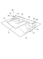
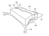
- the mold 100 is used for manufacturing a preform.
- the mold 100 includes a lower mold 110 and an upper mold 112.
- the lower mold 110 is a fixed mold and the upper mold 112 is a movable mold.
- the lower mold 110 includes a main body part 114 having a substantially rectangular shape in plan view, and two convex parts 116 and 118 provided on the upper surface of the main body part 114 in a longitudinal direction.
- a recess 120 is formed between the protrusion 116 and the protrusion 118 on the upper surface of the main body 114 of the lower mold 110.
- the convex portion 116 has a rectangular shape in plan view, a trapezoidal shape in front view, and a shape in which the upper part of the quadrangular pyramid is cut out horizontally.
- the shape of the convex portion 118 is the same as the shape of the convex portion 116.
- the front surface and the upper surface of the convex portion 116 are close to the concave portion 120, the surface of the concave portion 120, the portion corresponding to the concave portion 120 in the main body portion 114, and the front surface and upper surface of the convex portion 118.
- a portion near the concave portion 120 is a molding surface 122 for molding the stack.
- the lower mold 110 is provided with a plurality of screw holes 111.
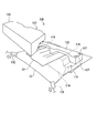
- the upper mold 112 includes a main mold 124 and a sub mold 126.
- the main mold 124 is a member that is pressed and molded in a state in which the stack is sandwiched between the lower mold 110 and is a portion that applies particularly large shear deformation to the stack in the upper mold 112.
- On the lower surface side portion of the main mold 124 a concave-convex shaped molding surface 128 complementary to the front side portion of the molding surface 122 of the lower die 110 is formed.
- the sub mold 126 is a member for molding the stack together with the main mold 124, and is a part that also functions as a fixing jig for fixing the stretchable sheet and the stack so as not to be displaced during molding.
- a concave-convex shaped molding surface 130 complementary to the back side portion of the molding surface 122 of the lower die 110 is formed on the lower die portion of the sub die 126.
- the sub die 126 is provided with a plurality of through holes 127 at positions corresponding to the screw holes 111 provided in the lower die 110. In a state where the sub mold 126 is close to the lower mold 110, a screw (not shown) is passed through the through hole 127, and is screwed into a screw hole 111 provided in the lower mold 110 to be tightened. 110 can be fixed.
- the mold material of the mold is not particularly limited, and examples thereof include metal, gypsum, and chemical wood. Of these, chemical wood is preferable from the viewpoint of cost and workability.
- the preform using the mold 100 is manufactured by the following method. As shown in FIG. 6, the stretchable sheet 10 is arranged on the lower mold 110 so as to cover the entire molding surface 122. Next, after the stack 12 is disposed on the stretchable sheet 10, the sub mold 126 in the upper mold 112 is installed on the back side of the upper surface of the lower mold 110, and the stretchable sheet 10 and the stack 12 are fixed so as not to be displaced.
- the stretchable sheet 10 is gripped by the clamps 132 and 134 included in the tension applying means to apply tension, so that the stretchable sheet 10 is in partial contact with the upper surfaces of the convex portions 116 and 118. Then, the elastic sheet 10 is tensioned.
- the stretchable sheet is preferably stretched.
- the stretch ratio of the stretchable sheet is preferably adjusted so that the deformation does not exceed the elastic region of the stretchable sheet when the stretchable sheet is stretched by the lower mold 110 and the upper mold 112 during molding. . Thereby, it becomes easy to sufficiently obtain an effect of suppressing appearance defects such as fiber meandering and wrinkling on the preform.
- the direction in which the tension is applied to the stretchable sheet is not particularly limited as long as the stretchable sheet is uniformly tensioned so that no wrinkles or loosened portions are generated on the stretchable sheet.
- the direction in which tension is applied to the stretchable sheet is the direction of the surface perpendicular to the direction in which the pair of molds are combined, that is, in the case of FIG. 7, the convex portion 116 and the convex portion 118 of the lower mold 110. It is preferable that the contact area between the upper surface and the stretchable sheet is as close as possible to the direction (horizontal direction) that is as large as possible. Accordingly, the stretchable sheet is easily stretched uniformly by the lower mold and the upper mold at the time of molding, so that it is easy to obtain an effect of suppressing appearance defects such as fiber meandering and wrinkling in the preform.
- the angle formed by the direction in which tension is applied to the stretchable sheet and the horizontal direction is preferably 45 ° or less, and more preferably 1 ° or less.
- the stack 12 is heated to soften the matrix resin composition contained in the stack 12.
- the stretchable sheet 10 and the lower mold 110 may also be heated at the same time.
- the heating temperature of the stack is not particularly limited as long as the matrix resin composition is softened, and varies depending on the type of the matrix resin composition, but is preferably 65 to 80 ° C, more preferably 70 to 75 ° C.
- the heating temperature of the stack is equal to or higher than the lower limit value, the matrix resin composition is softened and the reproducibility of the shape of the preform based on the mold is improved. If the heating temperature of the stack is not more than the upper limit value, it is easy to suppress the start of curing of the matrix resin composition during the molding of the preform.
- the method for heating the stack is not particularly limited, and examples thereof include heating with an infrared heater, hot air heating, and current heating to the prepreg.
- the main mold 124 in the upper mold 112 is brought close to the front side portion of the lower mold 110, and the lower mold 110 and the upper mold 112
- the stack 12 is sandwiched and pressed to be preformed.
- the stretchable sheet 10 is tensioned, so that the stack 12 is formed while the stretchable sheet 10 is stretched by the lower mold 110 and the upper mold 112.
- the stack 12 is pulled toward the outside of the mold (in this example, the front side of the mold) following the extension of the stretchable sheet 10, and the reinforcing fibers in the stack 12 can easily follow the deformation. Therefore, appearance defects such as fiber meandering and wrinkles are suppressed from occurring in the preform obtained.
- the surface pressure during stack preforming is preferably 0.01 to 0.1 MPa, more preferably 0.03 to 0.04 MPa. If the surface pressure is equal to or higher than the lower limit value, the stack can sufficiently follow the shape. If the surface pressure is less than or equal to the upper limit value, it is easy to suppress spreading of the reinforcing fibers at the stage of preforming.
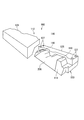
- the preform 20 After forming, the preform 20 is cooled, and the upper mold 112 is separated from the lower mold 110 and then removed from the lower mold 110, whereby the preform 20 shown in FIG. 9 is obtained.
- the tension applied to the stretchable sheet 10 when emphasizing the mass productivity of the preform 20, it is preferable to maintain the tension applied to the stretchable sheet 10 as it is even when the preform 20 is removed.
- the tension applied to the stretchable sheet 10 when releasing the preform 20 may be released as appropriate.
- the temperature of the preform when removing from the lower mold is preferably 30 ° C. or lower, and more preferably 23 ° C. or lower.
- the method for cooling the preform is not particularly limited, and for example, the preform can be cooled by standing to cool.
- the stretchable sheet is tensioned in one or more directions so that the angle ⁇ formed by the fiber direction of each prepreg (X) in the stack and the direction of tensioning the stretchable sheet is 15 to 75 °. It is preferable to mold the stack in a state in which it is left.
- the angle ⁇ is more preferably 30 ° or more. Further, by setting the angle ⁇ to 75 ° or less, it tends to be easy to prevent meandering of reinforcing fibers and tearing of the prepreg at the time of forming the stack.
- the angle ⁇ is more preferably 60 ° or less.
- the tensioned state of the stretchable sheet is maintained uniformly at the time of forming the stack, so that the stack is maintained while keeping the stretched sheet tensioned in two or more directions. It is more preferable to mold.
- the shape of the preform after preforming using an elastic sheet may not completely follow the shape of the molding surface of the mold, but in such a case, an elastic sheet may be used if necessary.
- the primary molded product after the first molding may be molded again with a pair of molds in a state where the stretchable sheet is not disposed, and the shape of the preform may be adjusted.
- the molding die 100 is used, as shown in FIG. 10, the primary molded product 20 ⁇ / b> A removed from the lower die 110 after molding using the stretchable sheet 10 is placed on the lower die 110 on which the stretchable sheet 10 is not disposed. To place.
- the sub mold 126 in the upper mold 112 is placed on the back side of the upper surface of the lower mold 110, and the primary molded product 20A is fixed so as not to be displaced.
- the primary molded product 20A is heated to soften the matrix resin composition in the primary molded product 20A.
- the lower mold 110 may also be heated at the same time.
- the heating temperature of the primary molded article may be a temperature at which the matrix resin composition is softened, and varies depending on the type of the matrix resin composition, but is preferably 65 to 80 ° C, more preferably 70 to 75 ° C.
- the heating temperature of the primary molded product is equal to or higher than the lower limit value, the matrix resin composition is softened and the reproducibility of the shape of the preform based on the mold is improved.
- the method for heating the primary molded product is not particularly limited, and examples thereof include the same method as the method for heating the stack.
- the main mold 124 in the upper mold 112 is brought close to the front side portion of the lower mold 110 while the primary molded product 20 ⁇ / b> A is heated.
- the primary molded product 20 ⁇ / b> A is sandwiched between the mold 110 and the upper mold 112 and molded by pressing.
- the surface pressure during molding of the primary molded product is preferably 0.01 to 0.1 MPa, more preferably 0.03 to 0.04. If the surface pressure is equal to or higher than the lower limit value, the stack can sufficiently follow the shape. If the surface pressure is less than or equal to the upper limit value, it is possible to prevent the reinforcing fibers from spreading at the stage of preforming.
- the preform 20 is cooled, the upper mold 112 is separated from the lower mold 110, and the preform 20 (secondary molded product) is removed from the lower mold 110.
- the temperature of the preform (secondary molded product) when removed from the lower mold is preferably 30 ° C. or less, and more preferably 23 ° C. or less.
- the method for cooling the preform (secondary molded product) is not particularly limited, and for example, it can be cooled by standing to cool.
- the preform obtained by the above-described method is placed in a mold in which a clearance corresponding to the shape of the fiber-reinforced composite material is set, and heated and pressed at a predetermined temperature and pressure using a press machine, thereby producing a fiber.
- a reinforced composite material is obtained. It is preferable to adjust the temperature of a mold used for compression molding to a predetermined temperature, and after compression molding, take out the fiber-reinforced composite material at that temperature. Thereby, it is not necessary to raise and lower the temperature of the mold, the molding cycle can be increased, and productivity is increased.
- the stack used in the manufacturing method of this embodiment is a laminate in which two or more sheet-like prepregs (X) in which reinforcing fibers are impregnated with a matrix resin composition are laminated so that the fiber directions are different.
- the reinforcing fiber is not particularly limited, and for example, a reinforcing fiber having an inorganic fiber, an organic fiber, a metal fiber, or a hybrid structure in which these are combined can be used.
- the inorganic fiber include carbon fiber, graphite fiber, silicon carbide fiber, alumina fiber, tungsten carbide fiber, boron fiber, and glass fiber.
- the organic fibers include aramid fibers, high density polyethylene fibers, other general nylon fibers, and polyester fibers.
- metal fibers include fibers such as stainless steel and iron, and carbon fibers coated with metal may be used. Among these, carbon fiber is preferable in consideration of mechanical properties such as strength of the fiber-reinforced composite material.
- the form of the reinforcing fiber base impregnated with the matrix resin composition is a form in which a large number of reinforcing fibers (long fibers) are aligned in one direction to form a UD sheet (unidirectional sheet), and reinforcing fibers (long fibers) are woven. And a form of cloth material (woven fabric).
- a reinforced fiber aligned in one direction may be impregnated with a matrix resin composition to form a prepreg, and then a cut may be made, and the reinforced fiber in the prepreg may be cut short.
- the fiber length of the reinforcing fiber between the cuts is preferably in the range of 10 to 100 mm. If the fiber length of the reinforcing fiber is not less than the lower limit, the mechanical properties of the fiber-reinforced composite material produced using the obtained preform are likely to be sufficiently high. Moreover, if the fiber length of the reinforcing fiber is equal to or less than the upper limit value, the stack can be easily formed into a complicated shape such as a three-dimensional shape.
- the stack is preferably one in which reinforcing fibers are aligned in two directions.
- a prepreg (X) in which a plurality of prepregs (UD prepreg) in which a reinforcing fiber aligned in one direction is impregnated with a matrix resin composition is laminated so that the directions of fiber axes are two directions.
- a laminate is preferred.
- a stack using a cross prepreg in which reinforcing fibers are woven in biaxial directions is also preferable as the prepreg (X).
- the UD sheet is arranged so that the reinforcing fibers are aligned in two directions.
- the preform has good moldability (followability to the mold), and a preform having a more excellent appearance tends to be produced.
- the angle formed by the fiber axes of the reinforcing fibers aligned in two directions is preferably 60 to 120 °, and more preferably 80 to 100 °. A typical angle is 90 °.
- the reinforcing fibers are arranged in approximately two directions in the entire stack. That is, examples of the weaving method of the cross material constituting the cross prepreg include plain weave, twill weave, satin weave, triaxial weave, and the like. Among them, plain weave, twill weave, satin in which reinforcing fibers are woven in the biaxial direction. It is preferable to use a woven cloth material because a preform having a more excellent appearance can be produced.
- the matrix resin composition a thermosetting resin composition or a thermoplastic resin composition may be used.
- the matrix resin is preferably a thermosetting resin from the viewpoint of excellent rigidity of the fiber-reinforced composite material.
- the thermosetting resin include epoxy resins, vinyl ester resins, unsaturated polyester resins, polyimide resins, maleimide resins, phenol resins, acrylic resins, and the like.
- an epoxy resin or a vinyl ester resin is preferable from the viewpoint of adhesiveness with the carbon fiber.
- thermoplastic resin examples include polyamide resin, acrylonitrile / butadiene / styrene (ABS) resin, acrylonitrile / ethylene / propylene / diene / styrene (AES) resin, acrylonitrile / styrene / acrylate (ASA) resin, and the like.
- ABS acrylonitrile / butadiene / styrene
- AES acrylonitrile / ethylene / propylene / diene / styrene
- ASA acrylonitrile / styrene / acrylate
- 1 type may be used independently and 2 or more types may be used together.
- a flame retardant material can also be mix
- the flame retardant material include bromine compounds, compounds containing phosphorus and nitrogen, phosphorus compounds, metal hydroxides, silicone compounds, hindered amine compounds, and the like.
- the resin weight content (RC) in the stack is preferably 10 to 60% by mass, and more preferably 30 to 40% by mass.
- R. C. Is equal to or greater than the lower limit, the mechanical properties of the fiber-reinforced composite material produced using the obtained preform tend to be sufficiently high.
- R. C. Is less than or equal to the upper limit, the stack can be easily formed into a complicated shape such as a three-dimensional shape. Note that R.D. C. Means a value measured by the measuring method described in JIS K 7071 5.1.
- the stretchable sheet is a stretchable resin or rubber sheet.
- As an elastic sheet when it is stretched by a mold in a state where it is placed while being tensioned between one mold and a stack, the shape of the mold does not exceed the elastic region. It is preferable to select according to.
- Examples of the resin stretchable sheet include a soft polyvinyl chloride sheet, a soft polyolefin sheet, and an ester urethane sheet.
- Examples of the rubber elastic sheet include a silicon rubber sheet, a natural rubber sheet, and a nitrile rubber sheet.
- As the elastic sheet one having high adhesion to the stack is preferable. Thereby, it becomes easy to suppress that the stack on the elastic sheet slips and becomes difficult to follow when the elastic sheet is stretched by the mold during molding.
- the stretchable sheet thickness is preferably in the range of 0.01 mm to 10 mm. This is because when the thickness of the stretchable sheet is 0.01 mm or more, the stretchable sheet is less likely to be damaged during the formation of the stack. A more preferable stretchable sheet thickness is 0.1 mm or more. Moreover, it is because there exists a tendency for the preform of the shape corresponding to a shaping
- the tensile elastic modulus of the stretchable sheet is preferably in the range of 0.1 to 40 MPa. This is because when the tensile elastic modulus of the stretchable sheet is 0.1 MPa or more, tension can be applied to the stack during molding, and wrinkles and the like tend to be less likely to occur in the resulting preform. .
- the tensile elastic modulus of the stretchable sheet is more preferably 10 MPa or more. Further, by setting the tensile elastic modulus of the stretchable sheet to 40 MPa or less, an excessive increase in the surface pressure of the stack during molding is suppressed and flexible movement of the stretchable sheet is obtained, resulting in fiber meandering of the preform. This is because it tends to be difficult.
- the tensile elastic modulus of the stretchable sheet is more preferably 20 MPa or less. The tensile modulus is a value measured according to JIS K 6251.
- the product having a product of thickness and tensile elastic modulus (thickness [mm] ⁇ tensile elastic modulus [MPa]) in the range of 1 to 6 can be used to improve the appearance. It becomes easy to stably produce a preform having good shape and excellent shape uniformity. This is because by setting this value to 1 or more, there is a tendency that an appropriate tension can be uniformly applied to the stack during molding.
- the product of the thickness and the tensile elastic modulus is more preferably 2 or more.
- the elastic sheet tends to flexibly expand and contract, so that the stack can be given sufficient shear deformation necessary for preform preforming. It is.
- the product of thickness and tensile elastic modulus is more preferably 4 or less.
- the method for manufacturing a fiber-reinforced composite material according to the present embodiment can be expanded and contracted by a molding die in a state where an elastic sheet is placed in a specific direction between one mold and a stack of the molding die.
- the stack is formed while stretching the sheet.
- the manufacturing method of this embodiment is particularly useful when a preform is once manufactured by preforming.
- the stretchable sheet is stretched and the stack follows the stretchable sheet and is pulled toward the outside of the mold, the reinforcing fibers in the stack also follow deformation in the direction in which the reinforcing fibers are not oriented. It becomes easy to do. As a result, appearance defects such as fiber meandering and wrinkles are suppressed from occurring in the fiber reinforced composite material.
- the manufacturing method of the fiber reinforced composite material of this embodiment is not limited to the method using the above-described mold 100.
- the manufacturing method of the fiber reinforced composite material of this embodiment may be a method of obtaining a two-dimensional curved surface preform and a fiber reinforced composite material without shear deformation.
- Example 1 a fiber reinforced composite material 30 having a three-dimensional shape (three-dimensional curved surface shape constituted by a combination of planes) in which the stack is illustrated in FIG.
- the following prepreg (X1) was used as the prepreg (X), and the following resin film (Y1) was used as the resin film (Y).
- Prepreg (X1) A sheet-like UD prepreg obtained by aligning carbon fibers in one direction and impregnating the epoxy resin composition (product name: TR391E250S, manufactured by Mitsubishi Rayon Co., Ltd.).
- Resin film (Y1) The same epoxy resin composition (Mitsubishi Rayon Co., Ltd., resin name: # 391) contained in the prepreg (X1) was adjusted to 60 ° C., and the thickness was 0 on the coater. Resin film obtained by forming a film to 3 mm.
- the prepreg (X1) is cut into four prepregs having a size of 250 mm length ⁇ 250 mm width and fiber directions of 0 °, 90 °, 45 °, and 135 °, respectively.
- X) 2, 3, 5, 6 were obtained.
- the resin film (Y1) was cut so that the size was 250 mm long ⁇ 250 mm wide to obtain a resin film (Y) 4.
- the four prepregs (X) 2, 3, 5, 6 after cutting and the resin film (Y) 4 after cutting have a laminated structure of [0 ° / 90 ° / resin.
- the laminated unit 1 was obtained by laminating the positions of the four sides so that the film (Y1) / 45 ° / 135 °] was obtained. That is, the laminated unit 1 is obtained by laminating the prepreg (X) 2 / prepreg (X) 3 / resin film (Y) 4 / prepreg (X) 5 / prepreg (X) 6 in order from the top. It was. Next, the laminated unit 1 was placed on a flat surface, covered with a bagging film, and the bagging film was evacuated for 45 minutes to eliminate air between the layers, whereby a stack 12 was obtained.
- the obtained stack 12 was preformed to produce a preform. Specifically, as shown in FIG. 12, after the stack 12 is arranged in the lower mold 110 manufactured by cutting out chemical wood so that the 0 ° direction of the prepreg (X) 2 of the first layer is the arrow direction. The operator pressed the stack 12 by hand to fit the upper groove of the lower mold 110 and pasted it. Next, as shown in FIG. 13, the stack 12 is pressed by the sub mold 126, and a screw (not shown) is passed through the through hole 127 provided in the sub mold 126 and screwed into the screw hole 111 provided in the lower mold 110 and tightened. Fixed.
- the entire stack 12 was heated using an infrared heater so that the surface temperature was 60 ° C.
- the main mold 124 of the upper mold 112 that moves up and down with an air cylinder (not shown) is lowered and brought closer to the lower mold 110, and the stack 12 is sandwiched between the upper mold 112 and the lower mold 110 to be spared. Molded.
- the screws passed through the through holes 127 were removed to remove the sub mold 126.
- the preform 50 was removed from the lower mold 110. The obtained preform 50 was free from wrinkles.
- the molding die for compression molding provided with a clearance corresponding to the thickness 1.1 mm of the target fiber reinforced composite material 30 is heated to 140 ° C., and the preform 50 is placed in the lower die of the molding die for compression molding. Then, the molding die for compression molding was closed, pressed and pressed at a set pressure of 4 MPa, and held for 10 minutes to obtain a fiber-reinforced composite material.
- the obtained fiber reinforced composite material was excellent in appearance and had stable mechanical properties in each direction.
- Example 2 In the same manner as in Example 1, three laminated units 1 and two resin films (Y) each having a size of 250 mm long ⁇ 250 mm wide were produced. Next, a preform was obtained in the same procedure as in Example 1 except that a stack having a laminated structure of laminated unit 1 / resin film (Y) / laminated unit 1 / resin film (Y) / laminated unit 1 was used. All the three lamination units 1 in the stack were arranged in the order of [0 ° / 90 ° / resin film (Y1) / 45 ° / 135 °] from the top.
- a fiber-reinforced composite material was obtained in the same manner as in Example 1 except that the clearance of the compression mold was set to 4.1 mm.
- the resulting preform was free of wrinkles.
- the obtained fiber reinforced composite material was excellent in appearance and had stable mechanical properties in each direction.
- Example 3 Two laminated units 1 are produced in the same manner as in Example 1, the prepreg (X) 6 of the fifth layer of the two laminated units 1 is faced, and the laminated structure in which the lamination order is symmetric in the thickness direction A preform was obtained in the same procedure as in Example 1 except that. A fiber-reinforced composite material was obtained in the same manner as in Example 1 except that the clearance of the compression mold was set to 2.3 mm. The resulting preform was free of wrinkles. Moreover, the obtained fiber reinforced composite material was excellent in appearance and had stable mechanical properties in each direction.
- Example 4 In the same manner as in Example 1, except that the fiber direction of the prepreg (X) 5 of the fourth layer in the laminated unit 1 was 30 ° and the fiber direction of the prepreg (X) 5 of the fifth layer was 120 °. A fiber reinforced composite material was prepared. The resulting preform was free of wrinkles. Moreover, the obtained fiber reinforced composite material was excellent in appearance and had stable mechanical properties in each direction.
- Example 5 In the same manner as in Example 1, except that the fiber direction of the fourth layer of the prepreg (X) 5 in the laminated unit 1 was 60 °, and the fiber direction of the fifth layer of the prepreg (X) 5 was 150 °. A fiber reinforced composite material was prepared. The resulting preform was free of wrinkles. Moreover, the obtained fiber reinforced composite material was excellent in appearance and had stable mechanical properties in each direction.
- Example 6 In the same manner as in Example 1, except that the fiber direction of the fourth layer of the prepreg (X) 5 in the laminated unit 1 was 50 ° and the fiber direction of the fifth layer of the prepreg (X) 5 was 130 °. A fiber reinforced composite material was prepared. The resulting preform was free of wrinkles. Moreover, the obtained fiber reinforced composite material was excellent in appearance and had stable mechanical properties in each direction.
- Example 7 A preform and a fiber reinforced composite material were used in the same manner as in Example 1 except that a resin film made of an epoxy resin composition (Made by Mitsubishi Rayon Co., Ltd., resin name: # 395) was used instead of the resin film (Y1). Was made.
- the resulting preform was free of wrinkles.
- the obtained fiber reinforced composite material was excellent in appearance and had stable mechanical properties in each direction.
- Example 8 A preform was obtained in the same manner as in Example 1 except that instead of the resin film (Y1), the same resin film as the resin film (Y1) was used except that the thickness was 0.5 mm. Further, a fiber-reinforced composite material was obtained in the same manner as in Example 1 except that the clearance of the compression mold was set to 1.3 mm. The resulting preform was free of wrinkles. Moreover, the obtained fiber reinforced composite material was excellent in appearance and had stable mechanical properties in each direction.
- Example 9 A preform was obtained in the same manner as in Example 1 except that instead of the resin film (Y1), the same resin film as the resin film (Y1) was used except that the thickness was 1.0 mm. Further, a fiber-reinforced composite material was obtained in the same manner as in Example 1 except that the clearance of the compression mold was set to 1.8 mm. The resulting preform was free of wrinkles. Moreover, the obtained fiber reinforced composite material was excellent in appearance and had stable mechanical properties in each direction.
- Example 10 instead of the prepreg (X1), a sheet-like cloth prepreg (product name: TR3110 391GMP, manufactured by Mitsubishi Rayon Co., Ltd.), in which a woven fabric obtained by weaving carbon fibers so that the fibers are orthogonal to each other, is impregnated with an epoxy resin composition.
- a preform was obtained in the same manner as in Example 1 except that.
- a fiber-reinforced composite material was obtained in the same manner as in Example 1 except that the clearance of the compression mold was set to 1.2 mm. The resulting preform was free of wrinkles.
- the obtained fiber reinforced composite material was excellent in appearance and had stable mechanical properties in each direction.
- Table 1 shows the stacking conditions of the stacks of each example and the evaluation results of preforms and fiber reinforced composite materials.
- the preform was evaluated as good if no wrinkles were observed and defective if wrinkles were observed.
- the evaluation of the fiber reinforced composite material was evaluated as defective if the appearance was excellent and the mechanical properties in each direction were stable, and defective if the appearance was poor or the strength was uneven or decreased.
- Example 11 A preform was manufactured using the mold 100 illustrated in FIG.
- the surplus area is provided so that the stretchable sheet is in contact with the width of 175 mm to 190 mm outside the portion where the preform is disposed on the upper surface of the convex portion 116 and the convex portion 118 in plan view.
- the height of the lower mold 110 is set to be twice to 2.5 times the height of the target preform in front view, and an excess region is provided in contact with the stretched stretchable sheet. .
- Polyvinyl chloride sheet (expandable sheet 10, manufactured by Okamoto Co., Ltd., product name: general PVC transparent and satin clear plastic film (film thickness: 0.2 mm, tensile elasticity) so as to cover the entire molding surface 122 on the lower mold 110 (Rate: 18.0 MPa), length 400 mm ⁇ width 400 mm ⁇ thickness 0.2 mm), and the stack (stack 12) obtained in Production Example 1 was further placed thereon. Next, the stretchable sheet 10 and the stack 12 were fixed by the sub mold 126.
- the stretchable sheet 10 is gripped by the clamps 132 and 134 provided in the tension applying means to apply tension, and the stretchable sheet 10 is tensioned so that the stretchable sheet 10 is partially in contact with the upper surfaces of the convex portions 116 and 118. .
- the direction in which tension is applied by the clamps 132 and 134 was set to 45 ° with respect to the fiber axis direction (0 °, 90 °) of the reinforcing fibers in the stack.
- the angle formed between the direction in which tension is applied to the stretchable sheet 10 and the horizontal direction was 0 °.
- the stack 12 is heated to 70 ° C.
- the main mold 124 of the upper mold 112 is brought close to the front side portion of the lower mold 110, and the stretch sheet 10 is stretched by the lower mold 110 and the upper mold 112. Was molded.
- the upper mold 112 was separated from the lower mold 110, and the primary molded product was demolded.
- the primary molded product was placed again on the lower mold 110 on which the stretchable sheet 10 was not arranged, and fixed by the sub mold 126.
- the primary molded product was heated to 70 ° C. by an infrared heater, the main mold 124 of the upper mold 112 was brought close to the front side portion of the lower mold 110, and the primary molded product was molded by the lower mold 110 and the upper mold 112. After the temperature of the molded preform reached 23 ° C., the upper mold 112 was separated from the lower mold 110 and the preform was removed.
- Example 12 As a stretchable sheet, a silicon rubber sheet (manufactured by TORR, product name: EL78, tensile elastic modulus: 16.0 MPa, length 300 mm ⁇ width 300 mm ⁇ thickness 1.6 mm) was used instead of the polyvinyl chloride sheet. A preform was obtained in the same manner as in Example 11.
- Example 13 As a stretchable sheet, a silicon rubber sheet (manufactured by TORR, product name: EL78, tensile elastic modulus: 16.0 MPa, length 300 mm ⁇ width 300 mm ⁇ thickness 1.6 mm) is used instead of the polyvinyl chloride sheet, and further with a paper tape. A preform was obtained in the same manner as in Example 11 except that the sheet was pulled and tensioned in all directions in the surface direction.
- Example 14 Except for using a natural rubber sheet (manufactured by Seatec Co., Ltd., product name: RN111 (tensile elastic modulus: about 10 MPa, length 300 mm ⁇ width 300 mm ⁇ thickness 1.0 mm) instead of the polyvinyl chloride sheet as the stretchable sheet. A preform was obtained in the same manner as in Example 11.
- RN111 tensile elastic modulus: about 10 MPa, length 300 mm ⁇ width 300 mm ⁇ thickness 1.0 mm
- Table 2 shows the manufacturing conditions and evaluation results of the examples.
- Example 15 A preform was obtained under the same conditions as in Example 11 except that the stack used in Example 1 was used. In addition, a fiber-reinforced composite material was produced from the obtained preform under the same conditions as in Example 1. The obtained preform and the fiber reinforced composite material were both free from wrinkles and had a good appearance. In this fiber reinforced composite material, the mechanical properties in each direction were also stable.
Abstract
Description
本願は、2015年7月8日に、日本に出願された特願2015-136824号に基づき優先権を主張し、その内容をここに援用する。 The present invention relates to a method for producing a fiber-reinforced composite material and a fiber-reinforced composite material.
This application claims priority on July 8, 2015 based on Japanese Patent Application No. 2015-136824 for which it applied to Japan, and uses the content for it here.
しかし、前記方法では、成形するスタックをその都度クランプで把持する必要があるため、製造工程が煩雑になる。また、張力を付与するためにスタックをクランプで直接把持するため、把持された部分において強化繊維が蛇行したり、損傷が生じたりすることがある。スタックに、予め製品となる部分に加えて余剰部分を設けておき、前記余剰部分をクランプで把持する方法もある。しかし、前記方法は成形後に余剰部分を切断除去する必要があり、工程がさらに増えて製造がより煩雑化するため、量産化には不向きである。 On the other hand, when manufacturing a preform, a method has also been proposed in which a tension is applied to a stack to be molded to promote followability in a direction in which reinforcing fibers are not oriented to improve moldability (
However, in the above method, since the stack to be formed needs to be held with a clamp each time, the manufacturing process becomes complicated. In addition, since the stack is directly gripped by a clamp in order to apply tension, the reinforcing fiber may meander or damage may occur in the gripped portion. There is also a method in which a surplus portion is provided in advance on the stack in addition to a portion to be a product, and the surplus portion is gripped with a clamp. However, the above method is not suitable for mass production because it is necessary to cut and remove the surplus portion after molding, which further increases the number of steps and makes the production more complicated.
[1]連続して配列された複数本の強化繊維にマトリクス樹脂組成物が含浸された複数のシート状のプリプレグ(X)が、繊維方向が異なるように積層されたスタックを、一対の型を備える成形型により立体形状に成形する、繊維強化複合材料の製造方法。
[2]前記スタックを予備成形してプリフォームとし、さらに前記プリフォームを圧縮成形して繊維強化複合材料を得る、[1]に記載の繊維強化複合材料の製造方法。
[3]前記スタックとして、複数の前記プリプレグ(X)と、樹脂組成物からなる1つ以上の樹脂フィルム(Y)(ただし、前記プリプレグ(X)を除く。)とが積層されたスタックを用いる、[1]又は[2]に記載の繊維強化複合材料の製造方法。
[4]前記スタックとして、プリプレグ(X)/プリプレグ(X)/樹脂フィルム(Y)/プリプレグ(X)/プリプレグ(X)の5層構成の積層ユニットを含み、第1層のプリプレグ(X)の繊維方向を0°としたとき、第2層、第4層及び第5層のプリプレグ(X)の繊維方向がそれぞれ15~165°であり、かつ各層の繊維方向が異なるスタックを用いる、[3]に記載の繊維強化複合材料の製造方法。
[5]前記第2層のプリプレグ(X)の繊維方向が85~95°であり、前記第4層のプリプレグ(X)の繊維方向が30~60°であり、前記第5層のプリプレグ(X)の繊維方向が120~150°である、[4]に記載の繊維強化複合材料の製造方法。
[6]前記スタックとして、2つ以上の前記積層ユニットを含み、かつ厚さ方向に隣り合う前記積層ユニットの間に前記樹脂フィルム(Y)が挟まれるように積層されたスタックを用いる、[4]又は[5]に記載の繊維強化複合材料の製造方法。
[7]前記スタックとして、同一の積層構成の2つの前記積層ユニットを含み、かつそれら積層ユニットが、それぞれの積層順序が厚さ方向において対称となるように積層されたスタックを用いる、[4]~[6]のいずれかに記載の繊維強化複合材料の製造方法。
[8]前記スタックとして、前記第4層の繊維方向と前記第5層の繊維方向の角度の差が90°である積層ユニットを含むスタックを用いる、[5]~[7]のいずれかに記載の繊維強化複合材料の製造方法。
[9]前記スタックを、平面に展開できない立体形状に成形する、[1]~[8]のいずれかに記載の繊維強化複合材料の製造方法。
[10]前記プリプレグ(X)に含まれるマトリックス樹脂組成物と、前記樹脂フィルム(Y)に含まれる樹脂組成物の組成が同一である、[3]~[9]のいずれかに記載の繊維強化複合材料の製造方法。
[11]前記樹脂フィルム(Y)の厚みが0.1~1mmである、[3]~[10]のいずれかに記載の繊維強化複合材料の製造方法。
[12]前記プリプレグ(X)として、クロスプリプレグを用いる、[1]~[11]のいずれかに記載の繊維強化複合材料の製造方法。
[13]下記樹脂層A~Eがこの順番に積層され、樹脂層A、B、D、Eのそれぞれの2層間において平面視で強化繊維の繊維方向がなす角度のうち、最小の角度が45°以下である、繊維強化複合材料。
樹脂層A、B、D、E:一方向に引き揃えられた強化繊維を含む樹脂層。
樹脂層C:一方向に引き揃えられた強化繊維を含まない樹脂層。
[14]前記樹脂層Aの強化繊維の繊維方向を0°としたとき、前記樹脂層B、前記樹脂層D及び前記樹脂層Eの強化繊維の繊維方向がそれぞれ15~165°である、[13]に記載の繊維強化複合材料。
[15]前記の最小の角度が15~45°である、[13]又は[14]に記載の繊維強化複合材料。
[16]前記成形型を構成する前記の一対の型のうちの一方の型と前記スタックとの間に、樹脂製又はゴム製の伸縮シートを特定の方向に緊張させながら配置した状態で前記一対の型を近接させ、前記一対の型によって前記伸縮シートを引き延ばしながら前記スタックを成形する、[1]~[12]のいずれかに記載の繊維強化複合材料の製造方法。
[17]前記一対の型が下型と上型とからなり、前記下型の成形面における上型に対向する部分に前記伸縮シートが部分的に接するように、前記伸縮シートを緊張させながら配置し、前記伸縮シート上に前記スタックを配置した状態で、前記上型と前記下型とを近接させて前記スタックを成形する、[16]に記載の繊維強化複合材料の製造方法。
[18]前記の伸縮シートを用いた予備成形によりプリフォームを得た後に、前記伸縮シートを配置しない状態で前記一対の型により前記プリフォームを再び圧縮成形して繊維強化複合材料とする、[16]又は[17]に記載の繊維強化複合材料の製造方法。
[19]前記スタック中の強化繊維が二方向以上に引き揃えられている、[16]~[18]のいずれかに記載の繊維強化複合材料の製造方法。
[20]前記スタックにおける各プリプレグ(X)の繊維方向と、前記伸縮シートを緊張させる方向とがなす角度が15~75°となるように、一方向以上の方向に前記伸縮シートを緊張させた状態で前記スタックを成形する、[16]~[19]のいずれかに記載の繊維強化複合材料の製造方法。
[21]前記スタックにおける各プリプレグ(X)の繊維方向と、前記伸縮シートを緊張させる方向とがなす角度が30~60°である、[20]に記載の繊維強化複合材料の製造方法。 The present invention has the following configuration.
[1] A stack in which a plurality of sheet-like prepregs (X) in which a matrix resin composition is impregnated with a plurality of continuously arranged reinforcing fibers is laminated so that the fiber directions are different from each other is formed into a pair of molds. A method for producing a fiber-reinforced composite material, which is formed into a three-dimensional shape by a forming die provided.
[2] The method for producing a fiber-reinforced composite material according to [1], wherein the stack is preformed to form a preform, and the preform is further compression-molded to obtain a fiber-reinforced composite material.
[3] As the stack, a stack in which a plurality of the prepregs (X) and one or more resin films (Y) made of a resin composition (excluding the prepreg (X)) are stacked is used. , [1] or [2] The manufacturing method of the fiber reinforced composite material.
[4] The stack includes a prepreg (X) / prepreg (X) / resin film (Y) / prepreg (X) / prepreg (X) laminated unit having a five-layer structure, and the first layer of the prepreg (X) When the fiber direction is set to 0 °, the prepreg (X) of the second layer, the fourth layer, and the fifth layer each have a fiber direction of 15 to 165 °, and a stack having different fiber directions of each layer is used. 3] The manufacturing method of the fiber reinforced composite material of description.
[5] The fiber direction of the prepreg (X) of the second layer is 85 to 95 °, the fiber direction of the prepreg (X) of the fourth layer is 30 to 60 °, and the prepreg of the fifth layer ( The method for producing a fiber-reinforced composite material according to [4], wherein the fiber direction of X) is 120 to 150 °.
[6] As the stack, a stack including two or more of the stacked units and stacked such that the resin film (Y) is sandwiched between the stacked units adjacent in the thickness direction is used. [4 ] Or the manufacturing method of the fiber reinforced composite material as described in [5].
[7] The stack includes two stacked units having the same stacked configuration, and the stacked units are stacked so that their stacking order is symmetric in the thickness direction. [4] A method for producing a fiber-reinforced composite material according to any one of [6] to [6].
[8] The stack includes a stack including a stacked unit in which a difference in angle between the fiber direction of the fourth layer and the fiber direction of the fifth layer is 90 °, as described in any one of [5] to [7] The manufacturing method of the fiber reinforced composite material of description.
[9] The method for producing a fiber-reinforced composite material according to any one of [1] to [8], wherein the stack is formed into a three-dimensional shape that cannot be developed on a plane.
[10] The fiber according to any one of [3] to [9], wherein the matrix resin composition contained in the prepreg (X) and the resin composition contained in the resin film (Y) have the same composition. A method for producing a reinforced composite material.
[11] The method for producing a fiber-reinforced composite material according to any one of [3] to [10], wherein the resin film (Y) has a thickness of 0.1 to 1 mm.
[12] The method for producing a fiber-reinforced composite material according to any one of [1] to [11], wherein a cross prepreg is used as the prepreg (X).
[13] The following resin layers A to E are laminated in this order, and the minimum angle among the angles formed by the fiber directions of the reinforcing fibers in a plan view between the two layers of the resin layers A, B, D, and E is 45. ° Fiber reinforced composite material that is below.
Resin layers A, B, D, E: Resin layers including reinforcing fibers aligned in one direction.
Resin layer C: a resin layer not containing reinforcing fibers aligned in one direction.
[14] When the fiber direction of the reinforcing fibers of the resin layer A is 0 °, the fiber directions of the reinforcing fibers of the resin layer B, the resin layer D, and the resin layer E are 15 to 165 °, respectively. 13] The fiber-reinforced composite material described in [13].
[15] The fiber-reinforced composite material according to [13] or [14], wherein the minimum angle is 15 to 45 °.
[16] A pair of the pair of molds constituting the mold and the stack in a state in which a stretchable sheet made of resin or rubber is tensioned in a specific direction between the pair and the stack. The method for producing a fiber-reinforced composite material according to any one of [1] to [12], wherein the stack is formed while the molds are brought close together and the stretchable sheet is stretched by the pair of molds.
[17] The pair of molds are composed of a lower mold and an upper mold, and are arranged while tensioning the stretchable sheet so that the stretchable sheet is in partial contact with a portion of the molding surface of the lower mold facing the upper mold. The method for producing a fiber-reinforced composite material according to [16], wherein the stack is formed by bringing the upper mold and the lower mold close to each other in a state where the stack is disposed on the stretchable sheet.
[18] After a preform is obtained by preforming using the stretchable sheet, the preform is compression-molded again by the pair of molds in a state where the stretchable sheet is not disposed to obtain a fiber-reinforced composite material. 16] or the method for producing a fiber-reinforced composite material according to [17].
[19] The method for producing a fiber-reinforced composite material according to any one of [16] to [18], wherein the reinforcing fibers in the stack are aligned in two or more directions.
[20] The stretchable sheet is tensioned in one or more directions so that the angle formed by the fiber direction of each prepreg (X) in the stack and the direction of tensioning the stretchable sheet is 15 to 75 °. The method for producing a fiber-reinforced composite material according to any one of [16] to [19], wherein the stack is molded in a state.
[21] The method for producing a fiber-reinforced composite material according to [20], wherein an angle formed by a fiber direction of each prepreg (X) in the stack and a direction in which the stretchable sheet is tensioned is 30 to 60 °.
本発明の繊維強化複合材料は、繊維蛇行やシワ等の外観不良が抑制され、優れた外観と優れた機械特性が両立されている。 According to the method for producing a fiber-reinforced composite material of the present invention, a high-productivity, three-dimensional shape, particularly a curved surface that is not a developable surface (including a combination of a plurality of flat surfaces) while suppressing appearance defects such as fiber meandering and wrinkles. And a fiber reinforced composite material having excellent appearance and mechanical properties.
In the fiber-reinforced composite material of the present invention, appearance defects such as fiber meandering and wrinkles are suppressed, and both excellent appearance and excellent mechanical properties are achieved.
プリプレグの繊維方向とは、強化繊維が一方向に引き揃えられたUDプリプレグの場合はその強化繊維の配向方向とする。強化繊維が直交するように製織されたクロスプリプレグの場合は、その経糸の強化繊維の配向方向を繊維方向とする。その他の強化繊維布帛を基材としたプリプレグの場合は、プリプレグのシート面内における前記プリプレグを左右対称に2分する対称軸であって、繊維軸方向が当該対称軸の方向になっている強化繊維の成分が最大である対称軸の方向を繊維方向とする。 In this specification, the fiber direction of the prepreg in the stack is positive in the counterclockwise direction when the stack is viewed from the first layer side.
The fiber direction of the prepreg is the orientation direction of the reinforcing fiber in the case of a UD prepreg in which the reinforcing fibers are aligned in one direction. In the case of a cross prepreg woven so that the reinforcing fibers are orthogonal to each other, the orientation direction of the reinforcing fibers of the warp is defined as the fiber direction. In the case of a prepreg based on another reinforcing fiber fabric, the reinforcing axis is a symmetrical axis that bisects the prepreg in the sheet plane of the prepreg in a bilaterally symmetrical manner, and the fiber axis direction is the direction of the symmetrical axis. The direction of the axis of symmetry where the fiber component is maximum is taken as the fiber direction.
本発明の繊維強化複合材料の製造方法は、連続して配列された複数本の強化繊維にマトリクス樹脂組成物が含浸された複数のシート状のプリプレグ(X)が、繊維方向が異なるように積層されたスタックを、一対の型を備える成形型により立体形状に成形して繊維強化複合材料を得る方法である。本発明の繊維強化複合材料の製造方法は、スタックを一度の圧縮成形で繊維強化複合材料とする方法であってもよく、スタックを予備成形してプリフォームとし、さらに前記プリフォームを圧縮成形して繊維強化複合材料を得る方法であってもよい。繊維蛇行やシワ等の外観不良を抑制しつつ、可展面ではない曲面を有する三次元曲面形状等の繊維強化複合材料を得やすい点では、スタックを予備成形してプリフォームとし、さらに前記プリフォームを圧縮成形して繊維強化複合材料を得る方法が好ましい。 [Method for producing fiber-reinforced composite material]
In the method for producing a fiber-reinforced composite material of the present invention, a plurality of sheet-like prepregs (X) in which a matrix resin composition is impregnated with a plurality of continuously arranged reinforcing fibers are laminated so that the fiber directions are different. This is a method of obtaining a fiber-reinforced composite material by forming the stack thus obtained into a three-dimensional shape using a forming die having a pair of dies. The method for producing a fiber-reinforced composite material of the present invention may be a method in which a stack is formed into a fiber-reinforced composite material by a single compression molding. The stack is preformed into a preform, and the preform is further compression-molded. Thus, a method for obtaining a fiber-reinforced composite material may be used. From the viewpoint of easily obtaining a fiber-reinforced composite material such as a three-dimensional curved surface having a curved surface that is not a developable surface while suppressing appearance defects such as fiber meandering and wrinkles, the stack is preformed into a preform, and the preform is further formed. A method of compressing the reform to obtain a fiber reinforced composite material is preferable.
スタックは、連続して配列された複数本の強化繊維にマトリクス樹脂組成物が含浸された複数のシート状のプリプレグ(X)が、繊維方向が異なるように積層されたものである。このようなスタックを用いることで、機械特性に優れた立体形状の繊維強化複合材料を製造することができる。 (stack)
The stack is formed by laminating a plurality of sheet-like prepregs (X) in which a matrix resin composition is impregnated into a plurality of continuously arranged reinforcing fibers so that the fiber directions are different. By using such a stack, a three-dimensional fiber-reinforced composite material having excellent mechanical properties can be produced.
なお、[0°/θ1/樹脂フィルム(Y)/θ2/θ3]における0°は、繊維方向が0°のプリプレグ(X)を意味する。θ1、θ2及びθ3も同様に、それぞれ繊維方向がθ1、θ2、θ3のプリプレグ(X)を意味する。 In the laminated unit, the fiber direction of the second layer prepreg (X) is 85 to 95 °, the fiber direction of the fourth layer prepreg (X) is 30 to 60 °, and the fifth layer prepreg (X ) Is more preferably 120 to 150 °. That is, [0 ° / θ1 / resin film (Y) / θ2 / θ3] (where θ1 to θ3 are the second and fourth layers when the fiber direction of the prepreg (X) of the first layer is 0 °) And a fiber unit direction of the prepreg (X) of the fifth layer, and θ1 = 85 to 95 °, θ2 = 30 to 60 °, and θ3 = 120 to 150 °) are more preferable.
In addition, 0 ° in [0 ° / θ1 / resin film (Y) / θ2 / θ3] means prepreg (X) having a fiber direction of 0 °. Similarly, θ1, θ2, and θ3 mean prepregs (X) having fiber directions of θ1, θ2, and θ3, respectively.
また、θ2及びθ3が前記範囲内であれば、第4層及び第5層の部分をせん断変形させやすく、4軸に強化繊維が配向されている積層ユニットを含むスタックであってもシワの発生を抑制しつつ容易に成形することができる。また、得られる繊維強化複合材料には、4軸方向に強化繊維が比較的均等に配向されるため、機械特性を均等にすることができる。 The angle θ3 in the fiber direction of the prepreg (X) of the fifth layer is because it is easy to obtain a three-dimensional fiber reinforced composite material that has both excellent mechanical properties and excellent appearance while suppressing appearance defects such as wrinkles. 120 to 150 ° is preferable, 130 to 140 ° is more preferable, and 135 ° is particularly preferable.
In addition, if θ2 and θ3 are within the above range, wrinkles are generated even in a stack including a laminated unit in which reinforcing fibers are oriented on four axes, which easily shears the portions of the fourth layer and the fifth layer. It can be easily molded while suppressing the above. Further, in the obtained fiber-reinforced composite material, the reinforcing fibers are relatively evenly oriented in the four-axis directions, so that the mechanical properties can be made uniform.
なお、図2A~図2Dにおける破線は強化繊維の繊維方向を意味する。 As the laminated unit, the mechanical properties of the fiber reinforced composite material are the most uniform. Therefore, as shown in FIGS. 1 and 2A to 2D, the laminated structure is [0 ° / 90 ° / resin film (Y) / The
2A to 2D mean the fiber direction of the reinforcing fiber.
また、スタックとしては、[0°/θ1/樹脂フィルム(Y)/θ2/θ3/θ2/樹脂フィルム(Y)/θ1/0°]の積層構成のスタックとしてもよい。 The stack may include two stacked units having the same stacked configuration, and the stacked units may be stacked so that their stacking order is symmetric in the thickness direction. In other words, the stack may include two stack units, and the stack order of one stack unit and the stack order of the other stack unit may be mirror-symmetric with respect to each other. Specifically, for example, [0 ° / θ1 / resin film (Y) / θ2 / θ3 / resin film (Y) / θ3 / θ2 / resin film (Y) / θ1 / 0 °)] It is good. Further, a stack without the resin film (Y) between the laminated units may be used. For example, [0 ° / θ1 / resin film (Y) / θ2 / θ3 / θ3 / θ2 / resin film (Y) / θ1 / 0. °)].
The stack may be a stack having a laminated structure of [0 ° / θ1 / resin film (Y) / θ2 / θ3 / θ2 / resin film (Y) / θ1 / 0 °].
スタックに用いるプリプレグ(X)は、連続して配列された複数本の強化繊維にマトリクス樹脂組成物が含浸されたシート状のプリプレグである。
プリプレグ(X)の形態は、強化繊維が一方向に引き揃えられたUDプリプレグであってもよく、強化繊維が直交するように製織されたクロスプリプレグであってもよい。また、プリプレグ(X)は、その他のバイアスクロス、3軸クロス、Multi-axial Warp Knit等の強化繊維布帛を基材としたプリプレグであってもよい。 <Prepreg (X)>
The prepreg (X) used for the stack is a sheet-like prepreg in which a matrix resin composition is impregnated with a plurality of continuously arranged reinforcing fibers.
The form of the prepreg (X) may be a UD prepreg in which reinforcing fibers are aligned in one direction, or a cross prepreg woven so that the reinforcing fibers are orthogonal to each other. Further, the prepreg (X) may be a prepreg based on a reinforcing fiber fabric such as other bias cloth, triaxial cloth, or multi-axial warp kit.
スタックに用いる樹脂フィルム(Y)を形成する樹脂組成物としては、例えば、エポキシ樹脂、不飽和ポリエステル樹脂、アクリル樹脂、ビニルエステル樹脂、フェノール樹脂、ベンゾオキサジン樹脂等を含むものが挙げられる。これらの中でも、硬化後の強度を高くできることから、エポキシ樹脂を含む樹脂組成物が好ましい。樹脂フィルム(Y)を形成する樹脂組成物は、プリプレグ(X)を形成するマトリクス樹脂組成物と同じであってもよく、異なっていてもよい。得られる繊維強化複合材料を構成する各層の間の密着性の観点では、プリプレグ(X)に含まれるマトリックス樹脂組成物と同一の樹脂組成の樹脂フィルム(Y)を用いることが好ましい。 <Resin film (Y)>
Examples of the resin composition forming the resin film (Y) used for the stack include those containing an epoxy resin, an unsaturated polyester resin, an acrylic resin, a vinyl ester resin, a phenol resin, a benzoxazine resin, and the like. Among these, a resin composition containing an epoxy resin is preferable because the strength after curing can be increased. The resin composition forming the resin film (Y) may be the same as or different from the matrix resin composition forming the prepreg (X). From the viewpoint of adhesion between the layers constituting the obtained fiber-reinforced composite material, it is preferable to use a resin film (Y) having the same resin composition as the matrix resin composition contained in the prepreg (X).
繊維強化複合材料の製造方法としては、例えば、以下の工程(1)~(6)を有する方法が挙げられる。
(1)プリプレグ(X)2枚を、一方の繊維方向を0°とし、もう一枚のプリプレグ(X)の繊維方向がθ1となるように積層する。ただし、θ1は85~95°とする。
(2)工程(1)で得た積層体における繊維方向がθ1のプリプレグ(X)上に、樹脂フィルム(Y)を積層する。
(3)工程(2)で積層した樹脂フィルム(Y)上に、繊維方向がθ2となるようにプリプレグ(X)を積層し、さらに繊維方向がθ3となるようにプリプレグ(X)を積層し、5層構成の積層ユニットとする。ただし、θ2は30~60°、θ4は120~150°とする。
(4)必要に応じて積層ユニットと樹脂フィルム(Y)を重ねてスタックとする。
(5)工程(4)で得たスタックを予備成形してプリフォームを得る。
(6)工程(5)で得たプリフォームを一対の型を備える成形型にて圧縮成形し、立体形状を有する繊維強化複合材料を得る。 (Production method)
Examples of the method for producing a fiber reinforced composite material include a method having the following steps (1) to (6).
(1) Two prepregs (X) are laminated so that one fiber direction is 0 ° and the fiber direction of the other prepreg (X) is θ1. However, θ1 is 85 to 95 °.
(2) The resin film (Y) is laminated on the prepreg (X) having a fiber direction θ1 in the laminate obtained in the step (1).
(3) On the resin film (Y) laminated in the step (2), the prepreg (X) is laminated so that the fiber direction becomes θ2, and further the prepreg (X) is laminated so that the fiber direction becomes θ3. A laminated unit having a five-layer structure is used. However, θ2 is 30 to 60 °, and θ4 is 120 to 150 °.
(4) If necessary, the stacking unit and the resin film (Y) are stacked to form a stack.
(5) Preform the stack obtained in step (4) to obtain a preform.
(6) The preform obtained in step (5) is compression-molded with a molding die having a pair of dies to obtain a fiber-reinforced composite material having a three-dimensional shape.
なお、雄雌型とは、一方の型の凸部又は凹部に、他方の凹部又は凸部が対応する一対の型のことを意味する。 As a method of pre-molding the stack in step (5) to obtain a preform, for example, a method of manually sticking the stack against the mold, a stack is placed on the mold, and a rubber film or the like is placed thereon. Examples thereof include a method in which the inside is evacuated after placement and the stack is pressure-bonded to a mold, and a method in which the stack is clamped by a mold composed of a pair of male and female molds. Among these, a method of sandwiching the stack with a molding die is preferable because the preforming can be performed in a short time. In this case, it is more preferable to use a stretchable sheet made of resin or rubber as described later.
In addition, a male-female type | mold means a pair of type | mold with which the other recessed part or convex part respond | corresponds to the convex part or recessed part of one type | mold.
スタックの加熱方式としては、例えば、熱風式、赤外線式等が挙げられる。加熱方式としては、迅速に積層体を加熱できる点から、赤外線式が好ましい。 In the preforming, it is preferable to heat the stack as necessary. Thereby, the prepreg (X) and the resin film (Y) are softened. For example, when a laminated unit having a laminated configuration of [0 ° / θ1 / resin film (Y) / θ2 / θ3] is preformed, the first layer and the first layer are formed by softening the prepreg (X) and the resin film (Y). The pair of two layers and the pair of the fourth and fifth layers are easily moved independently without being affected by each other, and the degree of freedom of shear deformation independently increases. As a result, it becomes easy to perform preforming without generating wrinkles even in a stack in which reinforcing fibers are oriented in four or more axes.
Examples of the heating method of the stack include a hot air type and an infrared type. As a heating method, an infrared type is preferable because the laminate can be heated quickly.
その際、成形型は所定の温度に調温しておき、圧縮成形した後、その温度のまま繊維強化複合材料を取り出すことが好ましい。これにより、成形型の昇降温を行う必要がなくなり、成形サイクルを高めることができ、生産性が高まる。 In the step (6), for example, the preform obtained in the step (5) is placed in a mold in which a clearance corresponding to the shape of the fiber reinforced composite material is set, and a predetermined temperature and pressure are set using a press. The preform is cured by heating and pressurizing with a to obtain a fiber-reinforced composite material.
At that time, it is preferable to adjust the temperature of the mold to a predetermined temperature, and after compression-molding, take out the fiber-reinforced composite material at that temperature. Thereby, it is not necessary to raise and lower the temperature of the mold, the molding cycle can be increased, and productivity is increased.
樹脂層A、B、D、E:一方向に引き揃えられた強化繊維を含む樹脂層。
樹脂層C:一方向に引き揃えられた強化繊維を含まない樹脂層。 As a fiber-reinforced composite material obtained by a manufacturing method using a stack including a laminated unit, the following resin layers A to E are laminated in this order, and the two layers of the resin layers A, B, D, and E are viewed in plan view. Of the angles formed by the fiber directions of the reinforcing fibers, those having a minimum angle of 45 ° or less are preferable.
Resin layers A, B, D, E: Resin layers including reinforcing fibers aligned in one direction.
Resin layer C: a resin layer not containing reinforcing fibers aligned in one direction.
角度α1:樹脂層Aの強化繊維の繊維方向と樹脂層Bの強化繊維の繊維方向とがなす角度。
角度α2:樹脂層Aの強化繊維の繊維方向と樹脂層Dの強化繊維の繊維方向とがなす角度。
角度α3:樹脂層Aの強化繊維の繊維方向と樹脂層Eの強化繊維の繊維方向とがなす角度。
角度α4:樹脂層Bの強化繊維の繊維方向と樹脂層Dの強化繊維の繊維方向とがなす角度。
角度α5:樹脂層Bの強化繊維の繊維方向と樹脂層Eの強化繊維の繊維方向とがなす角度。
角度α6:樹脂層Dの強化繊維の繊維方向と樹脂層Eの強化繊維の繊維方向とがなす角度。 Of the angles formed by the fiber directions of the reinforcing fibers in a plan view between the two resin layers A, B, D, and E, the minimum angle is the smallest of the following angles α1 to α6.
Angle α1: An angle formed by the fiber direction of the reinforcing fiber of the resin layer A and the fiber direction of the reinforcing fiber of the resin layer B.
Angle α2: An angle formed by the fiber direction of the reinforcing fiber of the resin layer A and the fiber direction of the reinforcing fiber of the resin layer D.
Angle α3: An angle formed by the fiber direction of the reinforcing fiber of the resin layer A and the fiber direction of the reinforcing fiber of the resin layer E.
Angle α4: An angle formed by the fiber direction of the reinforcing fiber of the resin layer B and the fiber direction of the reinforcing fiber of the resin layer D.
Angle α5: an angle formed by the fiber direction of the reinforcing fiber of the resin layer B and the fiber direction of the reinforcing fiber of the resin layer E.
Angle α6: an angle formed by the fiber direction of the reinforcing fiber of the resin layer D and the fiber direction of the reinforcing fiber of the resin layer E.
また、角度α1~α6のうち最小の角度は、より優れた機械特性が得られる点から、15~45°が好ましい。 As the fiber-reinforced composite material having the resin layers A to E, the resin layer B, the resin layer D, and the resin layer B can be obtained when the fiber direction of the reinforcing fiber of the resin layer A is 0 ° from the viewpoint that more excellent mechanical properties are obtained. The fiber directions of the reinforcing fibers of the resin layer E are each preferably 15 to 165 °.
In addition, the minimum angle among the angles α1 to α6 is preferably 15 to 45 ° from the viewpoint that more excellent mechanical characteristics can be obtained.
また、本実施形態の繊維強化複合材料の製造方法は、前記した樹脂フィルム(Y)を含むスタックを用いる方法と組み合わせることもできる。 The manufacturing method of the fiber reinforced composite material of this embodiment pre-forms the said stack with the shaping | molding die provided with a pair of type | molds prior to compression-molding the stack containing prepreg (X) and obtaining a fiber reinforced composite material. This is a suitable method for manufacturing a preform.
Moreover, the manufacturing method of the fiber reinforced composite material of this embodiment can also be combined with the method of using the stack containing an above described resin film (Y).
成形型100は、下型110と、上型112と、を備える。この例の成形型においては、下型110は固定型であり、上型112は可動型である。 As a specific example of the manufacturing method of the present invention, for example, a mode using the
The
下型110には複数のネジ穴111が設けられている。 In the
The
メイン型124は、下型110との間にスタックを挟み込んだ状態で加圧して成形するための部材であって、上型112においてスタックに特に大きなせん断変形をかける部分である。メイン型124の下面側の部分には、下型110の成形面122における正面側の部分と相補的な凹凸形状の成形面128が形成されている。 The
The
サブ型126には、下型110に設けられたネジ穴111に対応する位置に複数の貫通穴127が設けられている。サブ型126を下型110に近接させた状態で、貫通穴127にネジ(図示しない)を通し、下型110に設けたネジ穴111に螺入して締めることで、サブ型126を下型110上で固定できるようになっている。 The
The sub die 126 is provided with a plurality of through
図6に示すように、下型110上に、成形面122全体を覆うように伸縮シート10を配置する。次いで、伸縮シート10上にスタック12を配置した後、上型112におけるサブ型126を下型110の上面における背面側の部分に設置し、伸縮シート10及びスタック12をずれないように固定する。 For example, the preform using the
As shown in FIG. 6, the
伸縮シートに張力を付与して緊張させる際には、伸縮シートを延伸することが好ましい。この場合の伸縮シートの延伸倍率は、成形時に下型110と上型112によって伸縮シートが引き延ばされたときに、その変形が前記伸縮シートの弾性領域を超えないように調節することが好ましい。これにより、プリフォームに繊維蛇行やシワの発生等の外観不良が発生することを抑制する効果が充分に得られやすくなる。 Next, as shown in FIG. 7, the
When the tension is applied to the stretchable sheet, the stretchable sheet is preferably stretched. In this case, the stretch ratio of the stretchable sheet is preferably adjusted so that the deformation does not exceed the elastic region of the stretchable sheet when the stretchable sheet is stretched by the
この場合、伸縮シートに対して張力を付与する方向と、水平方向とがなす角度は、45°以下が好ましく、1°以下がより好ましい。 Further, the direction in which tension is applied to the stretchable sheet is the direction of the surface perpendicular to the direction in which the pair of molds are combined, that is, in the case of FIG. 7, the
In this case, the angle formed by the direction in which tension is applied to the stretchable sheet and the horizontal direction is preferably 45 ° or less, and more preferably 1 ° or less.
スタックの加熱温度は、マトリクス樹脂組成物が軟化する温度であればよく、マトリクス樹脂組成物の種類によっても異なるが、65~80℃が好ましく、70~75℃がより好ましい。スタックの加熱温度が下限値以上であれば、マトリクス樹脂組成物が軟化し、成形型に基づくプリフォームの形状の再現性が良好となる。スタックの加熱温度が上限値以下であれば、プリフォームの成形中にマトリクス樹脂組成物の硬化が開始することを抑制しやすい。 Next, the
The heating temperature of the stack is not particularly limited as long as the matrix resin composition is softened, and varies depending on the type of the matrix resin composition, but is preferably 65 to 80 ° C, more preferably 70 to 75 ° C. When the heating temperature of the stack is equal to or higher than the lower limit value, the matrix resin composition is softened and the reproducibility of the shape of the preform based on the mold is improved. If the heating temperature of the stack is not more than the upper limit value, it is easy to suppress the start of curing of the matrix resin composition during the molding of the preform.
下型から取り外す際のプリフォームの温度は、30℃以下が好ましく、23℃以下がより好ましい。
プリフォームを冷却する方法は、特に限定されず、例えば放冷によって冷却することができる。 After forming, the
The temperature of the preform when removing from the lower mold is preferably 30 ° C. or lower, and more preferably 23 ° C. or lower.
The method for cooling the preform is not particularly limited, and for example, the preform can be cooled by standing to cool.
また、前記角度φを75°以下とすることで、スタックの成形時の強化繊維の蛇行やプリプレグの裂けを防ぎやすい傾向にある。前記角度φは、より好ましくは60°以下である。 By setting the angle φ to 15 ° or more, sufficient formability tends to be obtained even if the shape of the finally obtained fiber-reinforced composite material is complicated. The angle φ is more preferably 30 ° or more.
Further, by setting the angle φ to 75 ° or less, it tends to be easy to prevent meandering of reinforcing fibers and tearing of the prepreg at the time of forming the stack. The angle φ is more preferably 60 ° or less.
例えば、成形型100を用いる場合、図10に示すように、伸縮シート10を用いた成形後に下型110から脱型させた一次成形物20Aを、伸縮シート10を配置していない下型110上に配置する。次いで、上型112におけるサブ型126を下型110の上面における背面側の部分に設置し、一次成形物20Aをずれないように固定する。 In addition, the shape of the preform after preforming using an elastic sheet may not completely follow the shape of the molding surface of the mold, but in such a case, an elastic sheet may be used if necessary. The primary molded product after the first molding may be molded again with a pair of molds in a state where the stretchable sheet is not disposed, and the shape of the preform may be adjusted.
For example, when the molding die 100 is used, as shown in FIG. 10, the primary molded
一次成形物の加熱温度は、マトリクス樹脂組成物が軟化する温度であればよく、マトリクス樹脂組成物の種類によっても異なるが、65~80℃が好ましく、70~75℃がより好ましい。一次成形物の加熱温度が下限値以上であれば、マトリクス樹脂組成物が軟化し、成形型に基づくプリフォームの形状の再現性が良好となる。一次成形物の加熱温度が上限値以下であれば、プリフォームの成形中にマトリクス樹脂組成物の硬化が開始することを抑制しやすい。
一次成形物を加熱する方法は、特に限定されず、例えば、スタックの加熱方法と同じ方法が挙げられる。 Next, the primary molded
The heating temperature of the primary molded article may be a temperature at which the matrix resin composition is softened, and varies depending on the type of the matrix resin composition, but is preferably 65 to 80 ° C, more preferably 70 to 75 ° C. When the heating temperature of the primary molded product is equal to or higher than the lower limit value, the matrix resin composition is softened and the reproducibility of the shape of the preform based on the mold is improved. If the heating temperature of the primary molded product is equal to or lower than the upper limit value, it is easy to suppress the start of curing of the matrix resin composition during the molding of the preform.
The method for heating the primary molded product is not particularly limited, and examples thereof include the same method as the method for heating the stack.
一次成形物の成形時の面圧は、0.01~0.1MPaが好ましく、0.03~0.04がより好ましい。面圧が下限値以上であれば、スタックが十分に形状追従できる。面圧が上限値以下であれば、予備成形の段階で強化繊維が広がることを抑制することができる。 Next, as in the case of the first molding using the
The surface pressure during molding of the primary molded product is preferably 0.01 to 0.1 MPa, more preferably 0.03 to 0.04. If the surface pressure is equal to or higher than the lower limit value, the stack can sufficiently follow the shape. If the surface pressure is less than or equal to the upper limit value, it is possible to prevent the reinforcing fibers from spreading at the stage of preforming.
下型から取り外す際のプリフォーム(二次成形物)の温度は、30℃以下が好ましく、23℃以下がより好ましい。
プリフォーム(二次成形物)を冷却する方法は、特に限定されず、例えば放冷によって冷却することができる。 After the molding, the
The temperature of the preform (secondary molded product) when removed from the lower mold is preferably 30 ° C. or less, and more preferably 23 ° C. or less.
The method for cooling the preform (secondary molded product) is not particularly limited, and for example, it can be cooled by standing to cool.
本実施形態の製造方法に用いるスタックは、強化繊維にマトリクス樹脂組成物が含浸されたシート状のプリプレグ(X)が、繊維方向が異なるように2枚以上積層された積層体である。 (stack)
The stack used in the manufacturing method of this embodiment is a laminate in which two or more sheet-like prepregs (X) in which reinforcing fibers are impregnated with a matrix resin composition are laminated so that the fiber directions are different.
無機繊維としては、炭素繊維、黒鉛繊維、炭化珪素繊維、アルミナ繊維、タングステンカーバイド繊維、ボロン繊維、ガラス繊維等が挙げられる。有機繊維としては、アラミド繊維、高密度ポリエチレン繊維、その他一般のナイロン繊維、ポリエステル繊維等が挙げられる。金属繊維としては、ステンレス、鉄等の繊維が挙げられ、また金属を被覆した炭素繊維でもよい。これらの中では、繊維強化複合材料の強度等の機械物性を考慮すると、炭素繊維が好ましい。 The reinforcing fiber is not particularly limited, and for example, a reinforcing fiber having an inorganic fiber, an organic fiber, a metal fiber, or a hybrid structure in which these are combined can be used.
Examples of the inorganic fiber include carbon fiber, graphite fiber, silicon carbide fiber, alumina fiber, tungsten carbide fiber, boron fiber, and glass fiber. Examples of the organic fibers include aramid fibers, high density polyethylene fibers, other general nylon fibers, and polyester fibers. Examples of metal fibers include fibers such as stainless steel and iron, and carbon fibers coated with metal may be used. Among these, carbon fiber is preferable in consideration of mechanical properties such as strength of the fiber-reinforced composite material.
複数のUDプリプレグが積層されたスタックを用いる場合は、強化繊維が二方向に引き揃えられた状態となるようにUDシートを配置するのが、予備成形時の目開き、繊維蛇行がより低減されるとともに、プリフォームの成形性(成形型への追随性)が良好であり、より優れた外観のプリフォームが製造できる傾向にあり好ましい。この場合、二方向に引き揃えられた強化繊維の繊維軸同士のなす角度は、60~120°が好ましく、80~100°がより好ましい。前記角度の典型は90°である。 The stack is preferably one in which reinforcing fibers are aligned in two directions. Specifically, a prepreg (X) in which a plurality of prepregs (UD prepreg) in which a reinforcing fiber aligned in one direction is impregnated with a matrix resin composition is laminated so that the directions of fiber axes are two directions. A laminate is preferred. A stack using a cross prepreg in which reinforcing fibers are woven in biaxial directions is also preferable as the prepreg (X).
In the case of using a stack in which a plurality of UD prepregs are stacked, the UD sheet is arranged so that the reinforcing fibers are aligned in two directions. In addition, the preform has good moldability (followability to the mold), and a preform having a more excellent appearance tends to be produced. In this case, the angle formed by the fiber axes of the reinforcing fibers aligned in two directions is preferably 60 to 120 °, and more preferably 80 to 100 °. A typical angle is 90 °.
すなわち、クロスプリプレグを構成するクロス材の織り方としては、例えば、平織、綾織、朱子織、三軸織等が挙げられるが、中でも2軸方向に強化繊維が織られた、平織、綾織、朱子織のクロス材を用いるのが、より優れた外観のプリフォームが製造できる傾向にあり好ましい。 Even when a cross prepreg is used as the prepreg (X), it is preferable for the same reason as described above that the reinforcing fibers are arranged in approximately two directions in the entire stack.
That is, examples of the weaving method of the cross material constituting the cross prepreg include plain weave, twill weave, satin weave, triaxial weave, and the like. Among them, plain weave, twill weave, satin in which reinforcing fibers are woven in the biaxial direction. It is preferable to use a woven cloth material because a preform having a more excellent appearance can be produced.
熱硬化性樹脂としては、例えば、エポキシ樹脂、ビニルエステル樹脂、不飽和ポリエステル樹脂、ポリイミド樹脂、マレイミド樹脂、フェノール樹脂、アクリル樹脂等が挙げられる。補強繊維として炭素繊維を用いる場合は、炭素繊維との接着性の点から、エポキシ樹脂又はビニルエステル樹脂が好ましい。 As the matrix resin composition, a thermosetting resin composition or a thermoplastic resin composition may be used. Among these, the matrix resin is preferably a thermosetting resin from the viewpoint of excellent rigidity of the fiber-reinforced composite material.
Examples of the thermosetting resin include epoxy resins, vinyl ester resins, unsaturated polyester resins, polyimide resins, maleimide resins, phenol resins, acrylic resins, and the like. When carbon fiber is used as the reinforcing fiber, an epoxy resin or a vinyl ester resin is preferable from the viewpoint of adhesiveness with the carbon fiber.
マトリクス樹脂組成物としては、1種を単独で使用してもよく、2種以上を併用してもよい。 Examples of the thermoplastic resin include polyamide resin, acrylonitrile / butadiene / styrene (ABS) resin, acrylonitrile / ethylene / propylene / diene / styrene (AES) resin, acrylonitrile / styrene / acrylate (ASA) resin, and the like.
As a matrix resin composition, 1 type may be used independently and 2 or more types may be used together.
この難燃性材料としては、例えば、臭素系化合物、リン及び窒素を含む化合物、リン系化合物、金属水酸化物、シリコーン系化合物、及びヒンダードアミン化合物等を挙げることができる。 A flame retardant material can also be mix | blended with a matrix resin composition as needed.
Examples of the flame retardant material include bromine compounds, compounds containing phosphorus and nitrogen, phosphorus compounds, metal hydroxides, silicone compounds, hindered amine compounds, and the like.
なお、スタックにおけるR.C.は、JIS K 7071 5.1記載の測定方法等により測定される値を意味する。 The resin weight content (RC) in the stack is preferably 10 to 60% by mass, and more preferably 30 to 40% by mass. R. C. Is equal to or greater than the lower limit, the mechanical properties of the fiber-reinforced composite material produced using the obtained preform tend to be sufficiently high. R. C. Is less than or equal to the upper limit, the stack can be easily formed into a complicated shape such as a three-dimensional shape.
Note that R.D. C. Means a value measured by the measuring method described in JIS K 7071 5.1.
伸縮シートは、伸縮性を有する樹脂製又はゴム製のシートである。
伸縮シートとしては、成形型における一方の型とスタックとの間で緊張させながら配置した状態で成形型によって引き延ばされたときに、その変形が弾性領域を超えないものを、成形型の形状に応じて選択することが好ましい。 (Elastic sheet)
The stretchable sheet is a stretchable resin or rubber sheet.
As an elastic sheet, when it is stretched by a mold in a state where it is placed while being tensioned between one mold and a stack, the shape of the mold does not exceed the elastic region. It is preferable to select according to.
ゴム製の伸縮シートとしては、シリコンゴムシート、天然ゴムシート、ニトリルゴムシート等が挙げられる。
伸縮シートとしては、スタックに対する密着性が高いものが好ましい。これにより、成形時に伸縮シートが成形型によって引き延ばされたときに伸縮シート上のスタックが滑って追従しにくくなることが抑制されやすくなる。 Examples of the resin stretchable sheet include a soft polyvinyl chloride sheet, a soft polyolefin sheet, and an ester urethane sheet.
Examples of the rubber elastic sheet include a silicon rubber sheet, a natural rubber sheet, and a nitrile rubber sheet.
As the elastic sheet, one having high adhesion to the stack is preferable. Thereby, it becomes easy to suppress that the stack on the elastic sheet slips and becomes difficult to follow when the elastic sheet is stretched by the mold during molding.
なお、引張弾性率は、JIS K 6251により測定される値である。 The tensile elastic modulus of the stretchable sheet is preferably in the range of 0.1 to 40 MPa. This is because when the tensile elastic modulus of the stretchable sheet is 0.1 MPa or more, tension can be applied to the stack during molding, and wrinkles and the like tend to be less likely to occur in the resulting preform. . The tensile elastic modulus of the stretchable sheet is more preferably 10 MPa or more. Further, by setting the tensile elastic modulus of the stretchable sheet to 40 MPa or less, an excessive increase in the surface pressure of the stack during molding is suppressed and flexible movement of the stretchable sheet is obtained, resulting in fiber meandering of the preform. This is because it tends to be difficult. The tensile elastic modulus of the stretchable sheet is more preferably 20 MPa or less.
The tensile modulus is a value measured according to JIS K 6251.
また、本実施形態の繊維強化複合材料の製造方法においては、スタックをその都度把持して張力を付与する必要がなく、把持によるスタックの損傷が生じることが抑制される。また、伸縮シートを緊張させた状態を維持しながら複数のスタックを連続成形することができるため、高い生産性でプリフォーム等を製造できる。 As described above, the method for manufacturing a fiber-reinforced composite material according to the present embodiment can be expanded and contracted by a molding die in a state where an elastic sheet is placed in a specific direction between one mold and a stack of the molding die. The stack is formed while stretching the sheet. The manufacturing method of this embodiment is particularly useful when a preform is once manufactured by preforming. In this embodiment, since the stretchable sheet is stretched and the stack follows the stretchable sheet and is pulled toward the outside of the mold, the reinforcing fibers in the stack also follow deformation in the direction in which the reinforcing fibers are not oriented. It becomes easy to do. As a result, appearance defects such as fiber meandering and wrinkles are suppressed from occurring in the fiber reinforced composite material.
Moreover, in the manufacturing method of the fiber reinforced composite material of this embodiment, it is not necessary to hold | maintain a stack and to give tension | tensile_strength each time, and it is suppressed that the damage of a stack by holding | grip arises. In addition, since a plurality of stacks can be continuously formed while maintaining the tensioned state of the stretchable sheet, a preform or the like can be manufactured with high productivity.
本実施形態の繊維強化複合材料の製造方法は、せん断変形を伴わない2次元曲面形状のプリフォーム及び繊維強化複合材料を得る方法であっても構わない。 In addition, the manufacturing method of the fiber reinforced composite material of this embodiment is not limited to the method using the above-described
The manufacturing method of the fiber reinforced composite material of this embodiment may be a method of obtaining a two-dimensional curved surface preform and a fiber reinforced composite material without shear deformation.
[実施例1]
本実施例では、スタックを図3に例示した、平面展開できない立体形状(平面の組み合わせで構成された三次元曲面形状)の繊維強化複合材料30を製造した。プリプレグ(X)として下記のプリプレグ(X1)を用い、樹脂フィルム(Y)として下記の樹脂フィルム(Y1)を用いた。
プリプレグ(X1):炭素繊維を一方向に引き揃えてエポキシ樹脂組成物を含浸して得られたシート状のUDプリプレグ(三菱レイヨン株式会社製、製品名:TR391E250S)。
樹脂フィルム(Y1):プリプレグ(X1)に含まれているのと同一のエポキシ樹脂組成物(三菱レイヨン株式会社製、樹脂名:#391)を60℃に調温し、コーターにて厚みが0.3mmとなるように製膜して得た樹脂フィルム。 EXAMPLES Hereinafter, although an Example demonstrates this invention concretely, this invention is not limited by the following description.
[Example 1]
In the present example, a fiber reinforced
Prepreg (X1): A sheet-like UD prepreg obtained by aligning carbon fibers in one direction and impregnating the epoxy resin composition (product name: TR391E250S, manufactured by Mitsubishi Rayon Co., Ltd.).
Resin film (Y1): The same epoxy resin composition (Mitsubishi Rayon Co., Ltd., resin name: # 391) contained in the prepreg (X1) was adjusted to 60 ° C., and the thickness was 0 on the coater. Resin film obtained by forming a film to 3 mm.
次いで、樹脂フィルム(Y1)をサイズが縦250mm×横250mmとなるように裁断し、樹脂フィルム(Y)4を得た。
次いで、図11に示すように、裁断後の4枚のプリプレグ(X)2、3、5、6と裁断後の樹脂フィルム(Y)4とを、積層構成が[0°/90°/樹脂フィルム(Y1)/45°/135°]となるように、それぞれの4辺の位置を合わせて積層して積層ユニット1を得た。すなわち、上から順にプリプレグ(X)2/プリプレグ(X)3/樹脂フィルム(Y)4/プリプレグ(X)5/プリプレグ(X)6の積層構成となるように積層して積層ユニット1を得た。
次いで、積層ユニット1を平面上に置き、バギングフィルムで覆い、バギングフィルム内を45分間真空脱気して、各層間のエアーを排除し、スタック12とした。 As shown in FIGS. 2A to 2D, the prepreg (X1) is cut into four prepregs having a size of 250 mm length × 250 mm width and fiber directions of 0 °, 90 °, 45 °, and 135 °, respectively. X) 2, 3, 5, 6 were obtained.
Next, the resin film (Y1) was cut so that the size was 250 mm long × 250 mm wide to obtain a resin film (Y) 4.
Next, as shown in FIG. 11, the four prepregs (X) 2, 3, 5, 6 after cutting and the resin film (Y) 4 after cutting have a laminated structure of [0 ° / 90 ° / resin. The
Next, the
次いで、図13に示すように、サブ型126でスタック12を押さえ、サブ型126に設けた貫通穴127にネジ(図示しない)を通して、下型110に設けたネジ穴111に螺入して締め、固定した。
次いで、赤外線ヒータを用いてスタック12全体を表面温度が60℃となるように加熱した。
次いで、図14に示すように、エアーシリンダー(図示しない)で上下する上型112のメイン型124を下降させて下型110に近づけ、スタック12を上型112と下型110で挟圧して予備成形した。 Using the molding die 100 illustrated in FIG. 5, the obtained
Next, as shown in FIG. 13, the
Next, the
Next, as shown in FIG. 14, the
次いで、図17に示すように、プリフォーム50を下型110から脱型した。得られたプリフォーム50にはシワの発生がなかった。 As shown in FIG. 15, after removing the
Next, as shown in FIG. 17, the
実施例1と同様の方法で、積層ユニット1を3つと、さらにサイズが縦250mm×横250mmの樹脂フィルム(Y)を2枚を作製した。次いで、積層ユニット1/樹脂フィルム(Y)/積層ユニット1/樹脂フィルム(Y)/積層ユニット1の積層構成のスタックとした以外は、実施例1と同じ手順でプリフォームを得た。スタックにおける3つの積層ユニット1は、全て上から[0°/90°/樹脂フィルム(Y1)/45°/135°]の積層順序とした。また、圧縮成形用成形金型のクリアランスを4.1mmに設定した以外は、実施例1と同様にして繊維強化複合材料を得た。
得られたプリフォームにはシワの発生がなかった。また、得られた繊維強化複合材料は外観に優れ、各方向の機械特性も安定していた。 [Example 2]
In the same manner as in Example 1, three
The resulting preform was free of wrinkles. Moreover, the obtained fiber reinforced composite material was excellent in appearance and had stable mechanical properties in each direction.
実施例1と同様にして積層ユニット1を2つ作製し、それら2つの積層ユニット1の第5層のプリプレグ(X)6を向かい合わせ、厚さ方向において積層順序が対称となる積層構成のスタックとした以外は、実施例1と同じ手順でプリフォームを得た。また、圧縮成形用成形金型のクリアランスを2.3mmに設定した以外は、実施例1と同様にして繊維強化複合材料を得た。
得られたプリフォームにはシワの発生がなかった。また、得られた繊維強化複合材料は外観に優れ、各方向の機械特性も安定していた。 [Example 3]
Two
The resulting preform was free of wrinkles. Moreover, the obtained fiber reinforced composite material was excellent in appearance and had stable mechanical properties in each direction.
積層ユニット1における第4層のプリプレグ(X)5の繊維方向を30°、第5層のプリプレグ(X)5の繊維方向を120°とした以外は、実施例1と同様にしてプリフォーム及び繊維強化複合材料を作製した。
得られたプリフォームにはシワの発生がなかった。また、得られた繊維強化複合材料は外観に優れ、各方向の機械特性も安定していた。 [Example 4]
In the same manner as in Example 1, except that the fiber direction of the prepreg (X) 5 of the fourth layer in the
The resulting preform was free of wrinkles. Moreover, the obtained fiber reinforced composite material was excellent in appearance and had stable mechanical properties in each direction.
積層ユニット1における第4層のプリプレグ(X)5の繊維方向を60°、第5層のプリプレグ(X)5の繊維方向を150°とした以外は、実施例1と同様にしてプリフォーム及び繊維強化複合材料を作製した。
得られたプリフォームにはシワの発生がなかった。また、得られた繊維強化複合材料は外観に優れ、各方向の機械特性も安定していた。 [Example 5]
In the same manner as in Example 1, except that the fiber direction of the fourth layer of the prepreg (X) 5 in the
The resulting preform was free of wrinkles. Moreover, the obtained fiber reinforced composite material was excellent in appearance and had stable mechanical properties in each direction.
積層ユニット1における第4層のプリプレグ(X)5の繊維方向を50°、第5層のプリプレグ(X)5の繊維方向を130°とした以外は、実施例1と同様にしてプリフォーム及び繊維強化複合材料を作製した。
得られたプリフォームにはシワの発生がなかった。また、得られた繊維強化複合材料は外観に優れ、各方向の機械特性も安定していた。 [Example 6]
In the same manner as in Example 1, except that the fiber direction of the fourth layer of the prepreg (X) 5 in the
The resulting preform was free of wrinkles. Moreover, the obtained fiber reinforced composite material was excellent in appearance and had stable mechanical properties in each direction.
樹脂フィルム(Y1)の代わりに、エポキシ樹脂組成物(三菱レイヨン株式会社製、樹脂名:#395)からなる樹脂フィルムを用いた以外は、実施例1と同様にしてプリフォーム及び繊維強化複合材料を作製した。
得られたプリフォームにはシワの発生がなかった。また、得られた繊維強化複合材料は外観に優れ、各方向の機械特性も安定していた。 [Example 7]
A preform and a fiber reinforced composite material were used in the same manner as in Example 1 except that a resin film made of an epoxy resin composition (Made by Mitsubishi Rayon Co., Ltd., resin name: # 395) was used instead of the resin film (Y1). Was made.
The resulting preform was free of wrinkles. Moreover, the obtained fiber reinforced composite material was excellent in appearance and had stable mechanical properties in each direction.
樹脂フィルム(Y1)の代わりに、厚みが0.5mmである以外は樹脂フィルム(Y1)と同じ樹脂フィルムを用いた以外は、実施例1と同様にしてプリフォームを得た。また、圧縮成形用成形金型のクリアランスを1.3mmに設定した以外は、実施例1と同様にして繊維強化複合材料を得た。
得られたプリフォームにはシワの発生がなかった。また、得られた繊維強化複合材料は外観に優れ、各方向の機械特性も安定していた。 [Example 8]
A preform was obtained in the same manner as in Example 1 except that instead of the resin film (Y1), the same resin film as the resin film (Y1) was used except that the thickness was 0.5 mm. Further, a fiber-reinforced composite material was obtained in the same manner as in Example 1 except that the clearance of the compression mold was set to 1.3 mm.
The resulting preform was free of wrinkles. Moreover, the obtained fiber reinforced composite material was excellent in appearance and had stable mechanical properties in each direction.
樹脂フィルム(Y1)の代わりに、厚みが1.0mmである以外は樹脂フィルム(Y1)と同じ樹脂フィルムを用いた以外は、実施例1と同様にしてプリフォームを得た。また、圧縮成形用成形金型のクリアランスを1.8mmに設定した以外は、実施例1と同様にして繊維強化複合材料を得た。
得られたプリフォームにはシワの発生がなかった。また、得られた繊維強化複合材料は外観に優れ、各方向の機械特性も安定していた。 [Example 9]
A preform was obtained in the same manner as in Example 1 except that instead of the resin film (Y1), the same resin film as the resin film (Y1) was used except that the thickness was 1.0 mm. Further, a fiber-reinforced composite material was obtained in the same manner as in Example 1 except that the clearance of the compression mold was set to 1.8 mm.
The resulting preform was free of wrinkles. Moreover, the obtained fiber reinforced composite material was excellent in appearance and had stable mechanical properties in each direction.
プリプレグ(X1)の代わりに、繊維が直交するように炭素繊維を製織して得られた織物にエポキシ樹脂組成物が含浸されたシート状のクロスプリプレグ(三菱レイヨン株式会社製、製品名:TR3110 391GMP)を用いた以外は、実施例1と同様にしてプリフォームを得た。また、圧縮成形用成形金型のクリアランスを1.2mmに設定した以外は、実施例1と同様にして繊維強化複合材料を得た。
得られたプリフォームにはシワの発生がなかった。また、得られた繊維強化複合材料は外観に優れ、各方向の機械特性も安定していた。 [Example 10]
Instead of the prepreg (X1), a sheet-like cloth prepreg (product name: TR3110 391GMP, manufactured by Mitsubishi Rayon Co., Ltd.), in which a woven fabric obtained by weaving carbon fibers so that the fibers are orthogonal to each other, is impregnated with an epoxy resin composition. A preform was obtained in the same manner as in Example 1 except that. A fiber-reinforced composite material was obtained in the same manner as in Example 1 except that the clearance of the compression mold was set to 1.2 mm.
The resulting preform was free of wrinkles. Moreover, the obtained fiber reinforced composite material was excellent in appearance and had stable mechanical properties in each direction.

一方向に引き揃えられた炭素繊維(三菱レイヨン社製、製品名:TR50S)に熱硬化性樹脂組成物(三菱レイヨン社製、樹脂名:#361)が含浸されたUDプリプレグ(厚さ約220μm、三菱レイヨン社製、製品名:TR361E250S)5枚を、繊維方向が0°/90°/0°/90°/0°の順となるように積層し、平面視で縦250mm×横250mmのプリプレグ積層体からなるスタックを得た。 [Production Example 1: Stack production]
A UD prepreg (thickness of about 220 μm) in which a carbon fiber (product name: TR50S manufactured by Mitsubishi Rayon Co., Ltd.) aligned in one direction is impregnated with a thermosetting resin composition (resin name: # 361 manufactured by Mitsubishi Rayon Co., Ltd.). (Manufactured by Mitsubishi Rayon Co., Ltd., product name: TR361E250S) 5 layers are laminated so that the fiber directions are in the order of 0 ° / 90 ° / 0 ° / 90 ° / 0 °, and are 250 mm long by 250 mm wide in plan view. A stack comprising a prepreg laminate was obtained.
図5に例示した成形型100を用いてプリフォームを製造した。成形型100では、平面視で凸部116及び凸部118の上面においてプリフォームが配置される部分の外側に175mm~190mmの幅で伸縮シートが接するように余剰領域を設けた。また、下型110の高さは、目的のプリフォームの正面視での高さに対して2倍~2.5倍の高さとして、引き延ばされた伸縮シートが接する余剰領域を設けた。 [Example 11]
A preform was manufactured using the
次いで、赤外線ヒータによりスタック12を70℃に加熱し、上型112のメイン型124を下型110の正面側の部分に近接させ、下型110と上型112によって伸縮シート10を引き延ばしながらスタック12を成形した。成形された一次成形物の温度が23℃になってから上型112を下型110から離間させ、一次成形物を脱型した。 Polyvinyl chloride sheet (
Next, the
伸縮シートとして、ポリ塩化ビニールシートの代わりに、シリコンゴムシート(TORR社製、製品名:EL78、引張弾性率:16.0MPa、縦300mm×横300mm×厚み1.6mm)を用いた以外は、実施例11と同様にしてプリフォームを得た。 [Example 12]
As a stretchable sheet, a silicon rubber sheet (manufactured by TORR, product name: EL78, tensile elastic modulus: 16.0 MPa, length 300 mm × width 300 mm × thickness 1.6 mm) was used instead of the polyvinyl chloride sheet. A preform was obtained in the same manner as in Example 11.
伸縮シートとして、ポリ塩化ビニールシートの代わりに、シリコンゴムシート(TORR社製、製品名:EL78、引張弾性率:16.0MPa、縦300mm×横300mm×厚み1.6mm)を用い、さらに紙テープによりシートを面方向における全方向へ引っ張って緊張させた以外は、実施例11と同様にしてプリフォームを得た。 [Example 13]
As a stretchable sheet, a silicon rubber sheet (manufactured by TORR, product name: EL78, tensile elastic modulus: 16.0 MPa, length 300 mm × width 300 mm × thickness 1.6 mm) is used instead of the polyvinyl chloride sheet, and further with a paper tape. A preform was obtained in the same manner as in Example 11 except that the sheet was pulled and tensioned in all directions in the surface direction.
伸縮シートとして、ポリ塩化ビニールシートの代わりに、天然ゴムシート(シーテック社製、製品名:RN111(引張弾性率:約10MPa、縦300mm×横300mm×厚み1.0mm)を用いた以外は、実施例11と同様にしてプリフォームを得た。 [Example 14]
Except for using a natural rubber sheet (manufactured by Seatec Co., Ltd., product name: RN111 (tensile elastic modulus: about 10 MPa, length 300 mm × width 300 mm × thickness 1.0 mm) instead of the polyvinyl chloride sheet as the stretchable sheet. A preform was obtained in the same manner as in Example 11.
各例で得られたプリフォームの外観を目視で確認し、以下の評価基準で評価した。
(評価基準)
○:プリフォームにシワが見られない。
△:プリフォームに僅かにシワが見られるが、問題ないレベルである。
×:プリフォームにシワが見られる。 [Appearance evaluation]
The appearance of the preform obtained in each example was visually confirmed and evaluated according to the following evaluation criteria.
(Evaluation criteria)
○: Wrinkles are not seen in the preform.
(Triangle | delta): Although a wrinkle is slightly seen in a preform, it is a level which is satisfactory.
X: Wrinkles are seen in the preform.

実施例1にて使用したスタックを使用した以外は、実施例11と同様な条件にてプリフォームを得た。また、得られたプリフォームから、実施例1と同様な条件にて繊維強化複合材料を作製した。得られたプリフォームと繊維強化複合材料はいずれもシワが発生しておらず外観が良好であり、この繊維強化複合材料においては、各方向の機械特性も安定していた。 [Example 15]
A preform was obtained under the same conditions as in Example 11 except that the stack used in Example 1 was used. In addition, a fiber-reinforced composite material was produced from the obtained preform under the same conditions as in Example 1. The obtained preform and the fiber reinforced composite material were both free from wrinkles and had a good appearance. In this fiber reinforced composite material, the mechanical properties in each direction were also stable.
2、3、5、6 プリプレグ(X)
4 樹脂フィルム(Y)
10 伸縮シート
12 スタック
100 成形型
110 下型
112 上型
114 本体部
116,118 凸部
120 凹部
122 成形面
124 メイン型
126 サブ型
128,130 成形面
132,134 クランプ 1
4 Resin film (Y)
DESCRIPTION OF
Claims (21)
- 連続して配列された複数本の強化繊維にマトリクス樹脂組成物が含浸された複数のシート状のプリプレグ(X)が、繊維方向が異なるように積層されたスタックを、一対の型を備える成形型により立体形状に成形する、繊維強化複合材料の製造方法。 A mold comprising a pair of molds in which a plurality of sheet-like prepregs (X) in which a matrix resin composition is impregnated with a plurality of continuously arranged reinforcing fibers are laminated so as to have different fiber directions A method for producing a fiber-reinforced composite material, which is formed into a three-dimensional shape by the method.
- 前記スタックを予備成形してプリフォームとし、さらに前記プリフォームを圧縮成形して繊維強化複合材料を得る、請求項1に記載の繊維強化複合材料の製造方法。 The method for producing a fiber-reinforced composite material according to claim 1, wherein the stack is preformed to form a preform, and the preform is further compression-molded to obtain a fiber-reinforced composite material.
- 前記スタックとして、複数の前記プリプレグ(X)と、樹脂組成物からなる1つ以上の樹脂フィルム(Y)(ただし、前記プリプレグ(X)を除く。)とが積層されたスタックを用いる、請求項1又は2に記載の繊維強化複合材料の製造方法。 The stack is a stack in which a plurality of the prepregs (X) and one or more resin films (Y) made of a resin composition (excluding the prepreg (X)) are stacked. A method for producing the fiber-reinforced composite material according to 1 or 2.
- 前記スタックとして、プリプレグ(X)/プリプレグ(X)/樹脂フィルム(Y)/プリプレグ(X)/プリプレグ(X)の5層構成の積層ユニットを含み、
第1層のプリプレグ(X)の繊維方向を0°としたとき、第2層、第4層及び第5層のプリプレグ(X)の繊維方向がそれぞれ15~165°であり、かつ各層の繊維方向が異なるスタックを用いる、請求項3に記載の繊維強化複合材料の製造方法。 The stack includes a laminated unit having a five-layer structure of prepreg (X) / prepreg (X) / resin film (Y) / prepreg (X) / prepreg (X),
When the fiber direction of the prepreg (X) of the first layer is 0 °, the fiber directions of the prepreg (X) of the second layer, the fourth layer, and the fifth layer are each 15 to 165 °, and the fibers of each layer The manufacturing method of the fiber reinforced composite material of Claim 3 using the stack from which directions differ. - 前記第2層のプリプレグ(X)の繊維方向が85~95°であり、前記第4層のプリプレグ(X)の繊維方向が30~60°であり、前記第5層のプリプレグ(X)の繊維方向が120~150°である、請求項4に記載の繊維強化複合材料の製造方法。 The fiber direction of the prepreg (X) of the second layer is 85 to 95 °, the fiber direction of the prepreg (X) of the fourth layer is 30 to 60 °, and the prepreg (X) of the fifth layer is The method for producing a fiber-reinforced composite material according to claim 4, wherein the fiber direction is 120 to 150 °.
- 前記スタックとして、2つ以上の前記積層ユニットを含み、かつ厚さ方向に隣り合う前記積層ユニットの間に前記樹脂フィルム(Y)が挟まれるように積層されたスタックを用いる、請求項4又は5に記載の繊維強化複合材料の製造方法。 The stack including two or more of the stacked units as the stack and stacked so that the resin film (Y) is sandwiched between the stacked units adjacent in the thickness direction is used. The manufacturing method of the fiber reinforced composite material as described in any one of.
- 前記スタックとして、同一の積層構成の2つの前記積層ユニットを含み、かつそれら積層ユニットが、それぞれの積層順序が厚さ方向において対称となるように積層されたスタックを用いる、請求項4~6のいずれか一項に記載の繊維強化複合材料の製造方法。 The stack according to any one of claims 4 to 6, wherein the stack includes two stacked units having the same stacked configuration, and the stacked units are stacked so that their stacking order is symmetrical in the thickness direction. The manufacturing method of the fiber reinforced composite material as described in any one.
- 前記スタックとして、前記第4層の繊維方向と前記第5層の繊維方向の角度の差が90°である積層ユニットを含むスタックを用いる、請求項5~7のいずれか一項に記載の繊維強化複合材料の製造方法。 The fiber according to any one of claims 5 to 7, wherein a stack including a laminated unit in which a difference in angle between the fiber direction of the fourth layer and the fiber direction of the fifth layer is 90 ° is used as the stack. A method for producing a reinforced composite material.
- 前記スタックを、平面に展開できない立体形状に成形する、請求項1~8のいずれか一項に記載の繊維強化複合材料の製造方法。 The method for producing a fiber-reinforced composite material according to any one of claims 1 to 8, wherein the stack is formed into a three-dimensional shape that cannot be developed on a plane.
- 前記プリプレグ(X)に含まれるマトリックス樹脂組成物と、前記樹脂フィルム(Y)に含まれる樹脂組成物の組成が同一である、請求項3~9のいずれか一項に記載の繊維強化複合材料の製造方法。 The fiber-reinforced composite material according to any one of claims 3 to 9, wherein the matrix resin composition contained in the prepreg (X) and the resin composition contained in the resin film (Y) have the same composition. Manufacturing method.
- 前記樹脂フィルム(Y)の厚みが0.1~1mmである、請求項3~10のいずれか一項に記載の繊維強化複合材料の製造方法。 The method for producing a fiber-reinforced composite material according to any one of claims 3 to 10, wherein the thickness of the resin film (Y) is 0.1 to 1 mm.
- 前記プリプレグ(X)として、クロスプリプレグを用いる、請求項1~11のいずれか一項に記載の繊維強化複合材料の製造方法。 The method for producing a fiber-reinforced composite material according to any one of claims 1 to 11, wherein a cross prepreg is used as the prepreg (X).
- 下記樹脂層A~Eがこの順番に積層され、樹脂層A、B、D、Eのそれぞれの2層間において平面視で強化繊維の繊維方向がなす角度のうち、最小の角度が45°以下である、繊維強化複合材料。
樹脂層A、B、D、E:一方向に引き揃えられた強化繊維を含む樹脂層。
樹脂層C:一方向に引き揃えられた強化繊維を含まない樹脂層。 The following resin layers A to E are laminated in this order, and the minimum angle among the angles formed by the fiber directions of the reinforcing fibers in plan view between the two layers of the resin layers A, B, D, and E is 45 ° or less. There is a fiber reinforced composite material.
Resin layers A, B, D, E: Resin layers including reinforcing fibers aligned in one direction.
Resin layer C: a resin layer not containing reinforcing fibers aligned in one direction. - 前記樹脂層Aの強化繊維の繊維方向を0°としたとき、前記樹脂層B、前記樹脂層D及び前記樹脂層Eの強化繊維の繊維方向がそれぞれ15~165°である、請求項13に記載の繊維強化複合材料。 The fiber direction of the reinforcing fibers of the resin layer B, the resin layer D, and the resin layer E is 15 to 165 °, respectively, when the fiber direction of the reinforcing fibers of the resin layer A is 0 °. The fiber-reinforced composite material described.
- 前記の最小の角度が15~45°である、請求項13又は14に記載の繊維強化複合材料。 The fiber-reinforced composite material according to claim 13 or 14, wherein the minimum angle is 15 to 45 °.
- 前記成形型を構成する前記の一対の型のうちの一方の型と前記スタックとの間に、樹脂製又はゴム製の伸縮シートを特定の方向に緊張させながら配置した状態で前記一対の型を近接させ、
前記一対の型によって前記伸縮シートを引き延ばしながら前記スタックを成形する、請求項1~12のいずれか一項に記載の繊維強化複合材料の製造方法。 The pair of molds in a state in which a stretchable sheet made of resin or rubber is placed in a specific direction between one of the pair of molds constituting the mold and the stack. Close
The method for producing a fiber-reinforced composite material according to any one of claims 1 to 12, wherein the stack is formed while the elastic sheet is stretched by the pair of molds. - 前記一対の型が下型と上型とからなり、
前記下型の成形面における上型に対向する部分に前記伸縮シートが部分的に接するように、前記伸縮シートを緊張させながら配置し、前記伸縮シート上に前記スタックを配置した状態で、前記上型と前記下型とを近接させて前記スタックを成形する、請求項16に記載の繊維強化複合材料の製造方法。 The pair of molds consists of a lower mold and an upper mold,
In a state where the stretchable sheet is placed while being tensioned so that the stretchable sheet is partially in contact with a portion facing the upper mold on the molding surface of the lower mold, and the stack is placed on the stretchable sheet, The method for producing a fiber-reinforced composite material according to claim 16, wherein the stack is formed by bringing a mold and the lower mold close to each other. - 前記の伸縮シートを用いた予備成形によりプリフォームを得た後に、前記伸縮シートを配置しない状態で前記一対の型により前記プリフォームを再び圧縮成形して繊維強化複合材料とする、請求項16又は17に記載の繊維強化複合材料の製造方法。 The preform is obtained by preforming using the stretchable sheet, and then the preform is compression-molded again by the pair of molds without arranging the stretchable sheet to obtain a fiber-reinforced composite material. 18. A method for producing a fiber-reinforced composite material according to item 17.
- 前記スタック中の強化繊維が二方向以上に引き揃えられている、請求項16~18のいずれか一項に記載の繊維強化複合材料の製造方法。 The method for producing a fiber-reinforced composite material according to any one of claims 16 to 18, wherein the reinforcing fibers in the stack are aligned in two or more directions.
- 前記スタックにおける各プリプレグ(X)の繊維方向と、前記伸縮シートを緊張させる方向とがなす角度が15~75°となるように、一方向以上の方向に前記伸縮シートを緊張させた状態で前記スタックを成形する、請求項16~19のいずれか一項に記載の繊維強化複合材料の製造方法。 In a state where the stretchable sheet is tensioned in one or more directions so that the angle formed by the fiber direction of each prepreg (X) in the stack and the direction of tensioning the stretchable sheet is 15 to 75 °. The method for producing a fiber-reinforced composite material according to any one of claims 16 to 19, wherein the stack is formed.
- 前記スタックにおける各プリプレグ(X)の繊維方向と、前記伸縮シートを緊張させる方向とがなす角度が30~60°である、請求項20に記載の繊維強化複合材料の製造方法。 The method for producing a fiber-reinforced composite material according to claim 20, wherein an angle formed by a fiber direction of each prepreg (X) in the stack and a direction in which the stretchable sheet is tensioned is 30 to 60 °.
Priority Applications (7)
| Application Number | Priority Date | Filing Date | Title |
|---|---|---|---|
| CN201680039476.3A CN107848163B (en) | 2015-07-08 | 2016-07-08 | The manufacturing method and fibre reinforced composites of fibre reinforced composites |
| JP2016548746A JP6222370B2 (en) | 2015-07-08 | 2016-07-08 | Manufacturing method of fiber reinforced composite material |
| KR1020187000100A KR101898420B1 (en) | 2015-07-08 | 2016-07-08 | Fabrication method of fiber reinforced composite material |
| EP20160917.9A EP3698952B1 (en) | 2015-07-08 | 2016-07-08 | Method for manufacturing fiber-reinforced composite material |
| EP16821480.7A EP3321055A4 (en) | 2015-07-08 | 2016-07-08 | Method for manufacturing fiber-reinforced composite material, and fiber-reinforced composite material |
| US15/739,332 US10960612B2 (en) | 2015-07-08 | 2016-07-08 | Method for manufacturing fiber-reinforced composite material and fiber-reinforced composite material |
| US17/194,017 US20210331429A1 (en) | 2015-07-08 | 2021-03-05 | Method for manufacturing fiber-reinforced composite material and fiber-reinforced composite material |
Applications Claiming Priority (2)
| Application Number | Priority Date | Filing Date | Title |
|---|---|---|---|
| JP2015136824 | 2015-07-08 | ||
| JP2015-136824 | 2015-07-08 |
Related Child Applications (2)
| Application Number | Title | Priority Date | Filing Date |
|---|---|---|---|
| US15/739,332 A-371-Of-International US10960612B2 (en) | 2015-07-08 | 2016-07-08 | Method for manufacturing fiber-reinforced composite material and fiber-reinforced composite material |
| US17/194,017 Division US20210331429A1 (en) | 2015-07-08 | 2021-03-05 | Method for manufacturing fiber-reinforced composite material and fiber-reinforced composite material |
Publications (1)
| Publication Number | Publication Date |
|---|---|
| WO2017007012A1 true WO2017007012A1 (en) | 2017-01-12 |
Family
ID=57685650
Family Applications (1)
| Application Number | Title | Priority Date | Filing Date |
|---|---|---|---|
| PCT/JP2016/070250 WO2017007012A1 (en) | 2015-07-08 | 2016-07-08 | Method for manufacturing fiber-reinforced composite material, and fiber-reinforced composite material |
Country Status (6)
| Country | Link |
|---|---|
| US (2) | US10960612B2 (en) |
| EP (2) | EP3321055A4 (en) |
| JP (1) | JP6222370B2 (en) |
| KR (1) | KR101898420B1 (en) |
| CN (2) | CN109774186B (en) |
| WO (1) | WO2017007012A1 (en) |
Cited By (6)
| Publication number | Priority date | Publication date | Assignee | Title |
|---|---|---|---|---|
| JP2019157079A (en) * | 2018-03-16 | 2019-09-19 | 三菱ケミカル株式会社 | Method for producing fiber-reinforced composite material formed article |
| CN110641043A (en) * | 2019-09-27 | 2020-01-03 | 中国人民解放军国防科技大学 | Layering process of X-shaped cap-shaped shell made of composite material |
| JP2020078948A (en) * | 2017-06-14 | 2020-05-28 | 三菱ケミカル株式会社 | Method of producing fiber-reinforced composite material molded product |
| WO2020111091A1 (en) | 2018-11-28 | 2020-06-04 | 三菱ケミカル株式会社 | Cloth prepreg, method for manufacturing cloth prepreg, fiber reinforced resin molded article, and method for manufacturing fiber reinforced resin molded article |
| WO2021161401A1 (en) * | 2020-02-10 | 2021-08-19 | 三菱重工業株式会社 | Molding jig and molding method |
| CN116774659A (en) * | 2023-06-25 | 2023-09-19 | 威海光威精密机械有限公司 | Method and system for indexing composite material production process and quality monitoring tracking record |
Families Citing this family (24)
| Publication number | Priority date | Publication date | Assignee | Title |
|---|---|---|---|---|
| CN109996658B (en) | 2016-11-29 | 2021-10-22 | 三菱化学株式会社 | Fiber-reinforced resin molded article and method for producing fiber-reinforced resin molded article |
| US10967585B2 (en) | 2017-03-16 | 2021-04-06 | Guerrilla Industries LLC | Composite structures and methods of forming composite structures |
| US20180345604A1 (en) * | 2017-06-02 | 2018-12-06 | Arris Composites Llc | Aligned fiber reinforced molding |
| WO2019046218A1 (en) * | 2017-08-28 | 2019-03-07 | Web Industries, Inc. | Thermoplastic composite master sheets and tapes and method |
| CN108419717B (en) * | 2018-03-30 | 2023-05-23 | 福建农林大学 | Fiber reinforced comb foundation and manufacturing method thereof |
| WO2019194090A1 (en) * | 2018-04-04 | 2019-10-10 | 三菱ケミカル株式会社 | Method for preparing fiber-reinforced resin molding material, and apparatus for preparing fiber-reinforced resin molding material |
| EP3623143B1 (en) * | 2018-09-11 | 2021-05-05 | Airbus Operations, S.L. | Methods for manufacturing curved omega stringers and z shaped stringers of composite material and for manufacturing a composite material stiffened panel with curvature |
| EP3863821A1 (en) * | 2018-10-12 | 2021-08-18 | Arris Composites Inc. | Preform charges and fixtures therefor |
| KR20200050521A (en) * | 2018-11-02 | 2020-05-12 | 코오롱데크컴퍼지트 주식회사 | Manufacturing method for preform and manufacturing method for composite using preform |
| EP3887132A1 (en) * | 2018-11-30 | 2021-10-06 | Arris Composites Inc. | Compression-molded fiber-composite parts and methods of fabrication |
| WO2020138473A1 (en) * | 2018-12-27 | 2020-07-02 | 三菱ケミカル株式会社 | Method for manufacturing preform, method for manufacturing composite material molded article, and mold |
| US20220297396A1 (en) * | 2019-05-20 | 2022-09-22 | Cytec Industries Inc. | Process for Compression Molding a Composite Article |
| US20220227072A1 (en) * | 2019-06-12 | 2022-07-21 | Mitsubishi Gas Chemical Company, Inc. | Method for producing molded article |
| JP7328833B2 (en) | 2019-08-30 | 2023-08-17 | 株式会社Subaru | Preform shaping apparatus, preform shaping method, and composite material molding method |
| JP7382117B2 (en) * | 2019-08-30 | 2023-11-16 | 株式会社Subaru | Preform shaping device, preform shaping method, and composite material molding method |
| CN114450108A (en) * | 2019-09-13 | 2022-05-06 | 强壮百伊结构股份公司 | System and method for designing and manufacturing optimized irregular objects with novel composite materials and resulting objects |
| CN113246576A (en) * | 2020-02-12 | 2021-08-13 | 上海飞机制造有限公司 | Preparation method of composite material laminate containing in-plane ripple defects |
| CN112590240B (en) * | 2020-11-17 | 2022-07-22 | 海鹰空天材料研究院(苏州)有限责任公司 | Thermal diaphragm preforming method suitable for cap-shaped structure composite material |
| CN112564351B (en) * | 2020-12-11 | 2023-12-05 | 陕西航空电气有限责任公司 | Composite sleeve for high-speed motor and preparation method thereof |
| EP4304841A1 (en) | 2021-03-09 | 2024-01-17 | Guerrilla Industries LLC | Composite structures and methods of forming composite structures |
| DE102021114149A1 (en) | 2021-06-01 | 2022-12-01 | Voith Patent Gmbh | Prepreg stack and method of manufacture |
| CN113696499B (en) * | 2021-08-26 | 2023-09-15 | 航天特种材料及工艺技术研究所 | Preparation method of assembled deformation-preventing light-weight carbon fiber composite material frame |
| JP2023157639A (en) * | 2022-04-15 | 2023-10-26 | 三菱重工業株式会社 | Laminated body and shaping method |
| CN115107299B (en) * | 2022-07-05 | 2024-02-09 | 江西昌兴航空装备股份有限公司 | Vertical-tail integral beam paving method |
Citations (6)
| Publication number | Priority date | Publication date | Assignee | Title |
|---|---|---|---|---|
| JPH03166914A (en) * | 1989-11-27 | 1991-07-18 | Agency Of Ind Science & Technol | Method for molding fiber reinforced thermoplastic synthetic resin |
| JPH04251715A (en) * | 1991-01-28 | 1992-09-08 | Nec Corp | Manufacture of carbon fiber reinforced composite material |
| JP2007168272A (en) * | 2005-12-22 | 2007-07-05 | Toray Ind Inc | Molding method of fiber-reinforced plastic molding and fiber-reinforced plastic molding |
| JP2011093253A (en) * | 2009-10-30 | 2011-05-12 | Kanazawa Univ | Press molding apparatus and press molding method |
| JP2014051077A (en) * | 2012-09-10 | 2014-03-20 | Mitsubishi Rayon Co Ltd | Production method of preform |
| JP2014208457A (en) * | 2013-03-28 | 2014-11-06 | 福井県 | Laminated molded body |
Family Cites Families (23)
| Publication number | Priority date | Publication date | Assignee | Title |
|---|---|---|---|---|
| JPH03501140A (en) * | 1987-08-03 | 1991-03-14 | アライド‐シグナル・インコーポレーテッド | impact resistant helmet |
| US4946640A (en) * | 1989-04-17 | 1990-08-07 | Shell Oil Company | Method for forming preformed material |
| US5264058A (en) * | 1992-08-24 | 1993-11-23 | Monsanto | Forming a shaped prelaminate and bilayer glazing of glass and plastic |
| FR2820359B1 (en) * | 2002-07-19 | 2003-10-24 | Vincent Duqueine | PROCESS AND DEVICE FOR MOLDING A PART IN COMPOSITE MATERIAL, AND ULM PROPELLER HUB WHICH THEY ALLOW THEM TO MAKE |
| US7249943B2 (en) * | 2003-08-01 | 2007-07-31 | Alliant Techsystems Inc. | Apparatus for forming composite stiffeners and reinforcing structures |
| DE602005015352D1 (en) * | 2004-10-22 | 2009-08-20 | Dow Global Technologies Inc | COMPOSITE MATERIALS FROM PLASTIC AND METHOD OF MANUFACTURING THEREOF |
| CA2656541A1 (en) * | 2006-08-18 | 2008-02-21 | Fukui Prefectural Government | Multiaxially reinforced laminated moldings and process for production thereof |
| EP2067592B1 (en) * | 2006-09-28 | 2020-07-15 | Toray Industries, Inc. | Process for producing composite prepreg base, layered base, and fiber-reinforced plastic |
| JP5332225B2 (en) | 2007-02-22 | 2013-11-06 | 東レ株式会社 | Manufacturing method of fiber reinforced composite material |
| FR2942600A1 (en) | 2009-02-27 | 2010-09-03 | Airbus France | METHOD FOR COMPACTING THE FINISHED SIDE OF A CONTINUOUS FIBER THERMOPLASTIC COMPOSITE PIECE |
| US8263205B2 (en) * | 2009-09-17 | 2012-09-11 | Hexcel Corporation | Method of molding complex composite parts using pre-plied multi-directional continuous fiber laminate |
| DE102009060696A1 (en) * | 2009-12-29 | 2011-06-30 | Airbus Operations GmbH, 21129 | Method and laying tool for producing a fiber fabric |
| US8603289B2 (en) * | 2010-09-20 | 2013-12-10 | Composite Solutions Inc. | Method for manufacturing composite components |
| EP2481558B1 (en) * | 2011-01-31 | 2016-06-22 | AIRBUS HELICOPTERS DEUTSCHLAND GmbH | Method for manufacturing of preimpregnated preform |
| CN105856661A (en) | 2012-02-20 | 2016-08-17 | 联想(北京)有限公司 | Workpiece, preparation method thereof and electronic equipment containing the workpiece |
| TWI490104B (en) * | 2012-09-10 | 2015-07-01 | Mitsubishi Rayon Co | Method for fabricating fiber-reinforced composite material molded product and fiber-reinforced composite material molded product |
| JP2014073580A (en) * | 2012-10-02 | 2014-04-24 | Mitsubishi Rayon Co Ltd | Method for producing preform |
| TWI520844B (en) * | 2012-10-30 | 2016-02-11 | 三菱麗陽股份有限公司 | Method for fabricating preform and fiber-reinforced resin molded article |
| EP2917031A4 (en) * | 2012-11-09 | 2016-12-07 | Dsm Ip Assets Bv | Three-dimensional articles from flexible composite materials |
| US20160009368A1 (en) * | 2013-02-28 | 2016-01-14 | The Boeing Company | Composite laminated plate having reduced crossply angle |
| DE102013209270B4 (en) | 2013-05-17 | 2024-03-14 | Bayerische Motoren Werke Aktiengesellschaft | Device for clamping a fiber arrangement |
| US10035323B2 (en) * | 2013-09-23 | 2018-07-31 | The Boeing Company | Composite textiles including spread filaments |
| JP6219732B2 (en) | 2014-01-21 | 2017-10-25 | 株式会社沖データ | Printing apparatus and printing method |
-
2016
- 2016-07-08 US US15/739,332 patent/US10960612B2/en active Active
- 2016-07-08 EP EP16821480.7A patent/EP3321055A4/en not_active Withdrawn
- 2016-07-08 EP EP20160917.9A patent/EP3698952B1/en active Active
- 2016-07-08 WO PCT/JP2016/070250 patent/WO2017007012A1/en active Application Filing
- 2016-07-08 CN CN201910093679.6A patent/CN109774186B/en active Active
- 2016-07-08 KR KR1020187000100A patent/KR101898420B1/en active IP Right Grant
- 2016-07-08 JP JP2016548746A patent/JP6222370B2/en active Active
- 2016-07-08 CN CN201680039476.3A patent/CN107848163B/en active Active
-
2021
- 2021-03-05 US US17/194,017 patent/US20210331429A1/en active Pending
Patent Citations (6)
| Publication number | Priority date | Publication date | Assignee | Title |
|---|---|---|---|---|
| JPH03166914A (en) * | 1989-11-27 | 1991-07-18 | Agency Of Ind Science & Technol | Method for molding fiber reinforced thermoplastic synthetic resin |
| JPH04251715A (en) * | 1991-01-28 | 1992-09-08 | Nec Corp | Manufacture of carbon fiber reinforced composite material |
| JP2007168272A (en) * | 2005-12-22 | 2007-07-05 | Toray Ind Inc | Molding method of fiber-reinforced plastic molding and fiber-reinforced plastic molding |
| JP2011093253A (en) * | 2009-10-30 | 2011-05-12 | Kanazawa Univ | Press molding apparatus and press molding method |
| JP2014051077A (en) * | 2012-09-10 | 2014-03-20 | Mitsubishi Rayon Co Ltd | Production method of preform |
| JP2014208457A (en) * | 2013-03-28 | 2014-11-06 | 福井県 | Laminated molded body |
Non-Patent Citations (1)
| Title |
|---|
| See also references of EP3321055A4 * |
Cited By (10)
| Publication number | Priority date | Publication date | Assignee | Title |
|---|---|---|---|---|
| JP2020078948A (en) * | 2017-06-14 | 2020-05-28 | 三菱ケミカル株式会社 | Method of producing fiber-reinforced composite material molded product |
| JP2019157079A (en) * | 2018-03-16 | 2019-09-19 | 三菱ケミカル株式会社 | Method for producing fiber-reinforced composite material formed article |
| JP7073811B2 (en) | 2018-03-16 | 2022-05-24 | 三菱ケミカル株式会社 | Method for manufacturing fiber-reinforced composite molded products |
| WO2020111091A1 (en) | 2018-11-28 | 2020-06-04 | 三菱ケミカル株式会社 | Cloth prepreg, method for manufacturing cloth prepreg, fiber reinforced resin molded article, and method for manufacturing fiber reinforced resin molded article |
| CN110641043A (en) * | 2019-09-27 | 2020-01-03 | 中国人民解放军国防科技大学 | Layering process of X-shaped cap-shaped shell made of composite material |
| WO2021161401A1 (en) * | 2020-02-10 | 2021-08-19 | 三菱重工業株式会社 | Molding jig and molding method |
| JPWO2021161401A1 (en) * | 2020-02-10 | 2021-08-19 | ||
| JP7317154B2 (en) | 2020-02-10 | 2023-07-28 | 三菱重工業株式会社 | Molding jig and molding method |
| CN116774659A (en) * | 2023-06-25 | 2023-09-19 | 威海光威精密机械有限公司 | Method and system for indexing composite material production process and quality monitoring tracking record |
| CN116774659B (en) * | 2023-06-25 | 2024-01-05 | 威海光威精密机械有限公司 | Method and system for indexing composite material production process and quality monitoring tracking record |
Also Published As
| Publication number | Publication date |
|---|---|
| CN109774186A (en) | 2019-05-21 |
| EP3321055A4 (en) | 2018-10-17 |
| JPWO2017007012A1 (en) | 2017-07-06 |
| CN109774186B (en) | 2021-09-03 |
| EP3698952B1 (en) | 2022-06-01 |
| EP3698952A1 (en) | 2020-08-26 |
| CN107848163B (en) | 2019-08-09 |
| US10960612B2 (en) | 2021-03-30 |
| US20180186101A1 (en) | 2018-07-05 |
| KR20180007000A (en) | 2018-01-19 |
| CN107848163A (en) | 2018-03-27 |
| US20210331429A1 (en) | 2021-10-28 |
| JP6222370B2 (en) | 2017-11-01 |
| EP3321055A1 (en) | 2018-05-16 |
| KR101898420B1 (en) | 2018-09-12 |
Similar Documents
| Publication | Publication Date | Title |
|---|---|---|
| JP6222370B2 (en) | Manufacturing method of fiber reinforced composite material | |
| JP5668874B2 (en) | Preform manufacturing method and fiber reinforced resin molded product manufacturing method | |
| NO174335B (en) | Method for producing molded articles of plastic composite material | |
| JP2008279753A (en) | Manufacturing method of fiber-reinforced plastics | |
| JP2014051077A (en) | Production method of preform | |
| JP4734983B2 (en) | Preform substrate and method for producing the same | |
| WO2020138473A1 (en) | Method for manufacturing preform, method for manufacturing composite material molded article, and mold | |
| US20200398461A1 (en) | Method of producing fiber-reinforced resin | |
| JP6369178B2 (en) | Preform manufacturing method, fiber-reinforced thermosetting resin molded product manufacturing method, and preform | |
| JPWO2019031478A1 (en) | Fiber-reinforced plastic and method for producing fiber-reinforced plastic | |
| JP6409569B2 (en) | Manufacturing method of fiber reinforced plastic | |
| JP6649016B2 (en) | Thermoformed article manufacturing method and thermoforming material | |
| JP2005254484A (en) | Method for producing thermosetting frp | |
| JP2017065066A (en) | Method and device for manufacturing preform | |
| AU2018100761A4 (en) | Composite shell and apparatus and method for forming same | |
| JP2014073580A (en) | Method for producing preform | |
| US20140184044A1 (en) | Chassis for a computing device | |
| JP6566120B2 (en) | Manufacturing method of fiber reinforced plastic | |
| JP2017148973A (en) | Method for manufacturing fiber-reinforced composite material molded product | |
| JP2006218782A (en) | Molding method of molded product made of frp having foam core | |
| JP2023097542A (en) | Method for manufacturing preform with three-dimensional shape configured by multiple preform elements | |
| JP2007062393A (en) | Method for producing thermosetting type fiber-reinforced plastic | |
| JPWO2020111091A1 (en) | Cross prepreg, manufacturing method of cross prepreg, manufacturing method of fiber reinforced resin molded product, fiber reinforced resin molded product | |
| JP2016011369A (en) | Carbon-fiber-reinforced thermoplastic resin composite material, and molded body using the same |
Legal Events
| Date | Code | Title | Description |
|---|---|---|---|
| ENP | Entry into the national phase |
Ref document number: 2016548746 Country of ref document: JP Kind code of ref document: A |
|
| 121 | Ep: the epo has been informed by wipo that ep was designated in this application |
Ref document number: 16821480 Country of ref document: EP Kind code of ref document: A1 |
|
| ENP | Entry into the national phase |
Ref document number: 20187000100 Country of ref document: KR Kind code of ref document: A |
|
| NENP | Non-entry into the national phase |
Ref country code: DE |
|
| WWE | Wipo information: entry into national phase |
Ref document number: 2016821480 Country of ref document: EP |