WO2017006880A1 - ボンディングキャピラリ - Google Patents
ボンディングキャピラリ Download PDFInfo
- Publication number
- WO2017006880A1 WO2017006880A1 PCT/JP2016/069699 JP2016069699W WO2017006880A1 WO 2017006880 A1 WO2017006880 A1 WO 2017006880A1 JP 2016069699 W JP2016069699 W JP 2016069699W WO 2017006880 A1 WO2017006880 A1 WO 2017006880A1
- Authority
- WO
- WIPO (PCT)
- Prior art keywords
- inclined surface
- wire
- bonding
- capillary
- bonding capillary
- Prior art date
- Legal status (The legal status is an assumption and is not a legal conclusion. Google has not performed a legal analysis and makes no representation as to the accuracy of the status listed.)
- Ceased
Links
Images





Classifications
-
- H—ELECTRICITY
- H10—SEMICONDUCTOR DEVICES; ELECTRIC SOLID-STATE DEVICES NOT OTHERWISE PROVIDED FOR
- H10W—GENERIC PACKAGES, INTERCONNECTIONS, CONNECTORS OR OTHER CONSTRUCTIONAL DETAILS OF DEVICES COVERED BY CLASS H10
- H10W72/00—Interconnections or connectors in packages
- H10W72/071—Connecting or disconnecting
- H10W72/0711—Apparatus therefor
- H10W72/07141—Means for applying energy, e.g. ovens or lasers
Definitions
- An aspect of the present invention generally relates to a bonding capillary.
- wire bonding is performed in which a semiconductor element and a lead frame are connected by a bonding wire (hereinafter referred to as “wire”).
- wire bonding one end of a wire is bonded to an electrode pad of a semiconductor element using a bonding capillary (first bond).
- first bond the bonding capillary
- second bond the wire is drawn and joined to the lead (second bond).
- bonding wires ultrasonic waves are applied in a state where the wires are pressed by a bonding capillary.
- a final bonded portion (stitch bond) between the wire and the lead and a temporary bonded portion (tail bond) between the wire and the lead are formed.
- the wire extending from the tail bond is cut (cut).
- the semiconductor device is manufactured by sealing the semiconductor element and the lead frame connected by the wire with a sealing resin.
- semiconductor devices are used in, for example, in-vehicle electronic devices, and are used in severe temperature cycle environments.
- a semiconductor device is used in a severe temperature cycle environment, a problem of peeling or cracking of the sealing resin may occur due to a difference in thermal expansion between the sealing resin and the metal.
- high environmental reliability temperature cycle reliability
- a method using a lead frame called a roughened lead frame has been proposed.
- a thick plated layer containing nickel or the like is formed on the surface of the roughened lead frame, and the surface of the plated layer is roughened. Due to the rough surface, the adhesion between the lead frame and the sealing resin can be improved.
- the present invention has been made on the basis of recognition of such problems, and an object of the present invention is to provide a bonding capillary that can improve bonding strength, improve wire segmentation, and suppress wear.
- 1st invention is the 1st press surface which presses the said wire through which the wire is penetrated, Comprising: It provided in the circumference
- the root mean square slope of the roughness curve element is smaller than the root mean square slope of the roughness curve element of the first inclined surface.
- the wire can be pressed by the rough first inclined surface during the main bonding, and the bonding strength of the stitch bond portion can be ensured. Furthermore, since the wire is pressed by the second inclined surface and the tapered surface at the time of temporary joining, the contact area between the bonding capillary and the wire is increased, and the joining strength of the tail bond portion can be improved. Further, when the wire is divided after joining, a large tensile force is generated on the wire by the first inclined surface having a large root mean square inclination. On the other hand, depending on the second inclined surface having a small root mean square inclination, a tensile force is hardly generated on the wire.
- the stress is maximized at a suitable position for cutting the wire (for example, the thinnest part of the wire) located near the boundary between the first inclined surface and the second inclined surface. For this reason, generation
- the root mean square slope of the roughness curve element of the first inclined surface is 8 ° or more
- the root mean square of the roughness curve element of the second inclined surface The square root inclination is a bonding capillary characterized by being 5 ° or less.
- the root mean square slope of the roughness curve element of the first inclined surface is 11 ° or more
- the roughness curve element of the second inclined surface Is a bonding capillary characterized by having a root mean square slope of 2 ° or less.
- the root mean square slope of the first inclined surface is 11 ° or more, and the root mean square slope of the second inclined surface is 2 ° or less.
- the difference between the root mean square slope of the first slope and the root mean square slope of the second slope is easily kept above a certain level. For this reason, it is possible to suppress a decrease in the difference between the tensile force generated on the wire by the first inclined surface and the tensile force generated on the wire by the second inclined surface.
- the bonding capillary is worn, the deformation mode of a microcrack that occurs at an appropriate position for cutting the wire becomes mode I, and the crack progresses. Accordingly, the wire breakability can be improved.
- the width of the second inclined surface is 2 of the outer diameter of the first pressing surface. % Or more and 8% or less.
- the bonding capillary when the width of the second inclined surface is 2% or more of the outer diameter of the first pressing surface when viewed along the axial direction, the maximum stress generated at the tip of the bonding capillary is reduced. It is possible to lower the critical stress that the material of the bonding capillary wears. Thereby, wear of the bonding capillary can be significantly suppressed. Furthermore, when the width of the second inclined surface is 8% or less of the outer diameter of the pressing surface when viewed along the axial direction, a stress capable of obtaining a sufficient bonding strength of the tail bond portion is generated. Can do.
- the maximum height Rz of the first inclined surface is 0.2 micrometers or more, and the maximum height of the second inclined surface is The thickness Rz is a bonding capillary characterized by being 0.16 micrometers or less.
- the wire can be pressed by the first inclined surface, so that sufficient bonding strength is obtained. Can be obtained.
- the maximum height Rz of the second inclined surface is 0.16 micrometers or less, sliding between the wire and the bonding capillary is promoted. Thereby, the parting property of a wire can be improved. As described above, occurrence of peeling failure can be suppressed.
- the maximum height Rz of the first inclined surface is 0.3 micrometers or more, and the maximum height of the second inclined surface is The thickness Rz is a bonding capillary characterized by being 0.10 micrometers or less.
- the maximum height Rz of the first inclined surface is 0.3 micrometers or more, even if the bonding capillary is worn, the maximum height Rz of the first inclined surface is more than a certain value. Easy to keep in. Thereby, even if the bonding capillary is worn, the wire can be held by the first inclined surface, so that a sufficient bonding strength can be obtained. Further, even when the bonding capillary is worn, the maximum height Rz of the second inclined surface is 0.10 micrometer or less, so that sliding between the wire and the bonding capillary can be promoted. Thereby, the parting property of a wire can be improved.
- an angle formed between a surface perpendicular to the axial direction and the second inclined surface is the angle perpendicular to the axial direction.
- a bonding capillary characterized by being smaller than an angle formed by a surface and the first inclined surface.
- An eighth invention is characterized in that, in any one of the first to seventh inventions, an angle formed by a surface perpendicular to the axial direction and the second inclined surface is 11 degrees or less. A bonding capillary.
- the angle between the surface perpendicular to the axial direction and the second inclined surface is 11 degrees or less, the stress that can obtain a sufficient bonding strength of the tail bond portion at the time of temporary bonding (The force with which the second pressing surface presses the wire) can be generated.
- the boundary between the first inclined surface and the second inclined surface is saw-shaped when viewed along the axial direction. It is a bonding capillary characterized by being.
- the skewness of the first inclined surface is ⁇ 0.3 or less, and the average height of the first inclined surface is 0.
- a bonding capillary characterized by having a thickness of .06 micrometers or more and 0.3 micrometers or less.
- this bonding capillary it is possible to reduce the shape change caused by wear during use. Even if the bonding is repeated, the initial wire cutting property and bonding strength can be maintained for a long period of time.
- the eleventh invention is the bonding capillary according to any one of the first to tenth inventions, wherein the kurtosis of the second inclined surface is 5.0 or less.
- FIG. 7A and FIG. 7B are photographic images illustrating bonding wires and leads.
- FIG. 8A and FIG. 8B are schematic diagrams for explaining wire cutting by the bonding capillary according to the present embodiment.
- FIG. 13A and FIG. 13B are views illustrating the tip of the bonding capillary according to this embodiment. It is a figure which illustrates the evaluation result of a bonding capillary. It is a figure which illustrates the evaluation result of a bonding capillary.
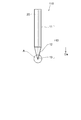
- FIG. 1 is a schematic view illustrating a bonding capillary according to this embodiment.
- FIG. 2 is a schematic enlarged view illustrating the tip shape of the bonding capillary according to this embodiment.
- FIG. 1 shows the entire bonding capillary 110.
- FIG. 2 shows an enlarged view of the region A shown in FIG.
- the bonding capillary 110 has a main body 10.
- the main body 10 is a cylindrical member and has an insertion hole 20.
- the insertion hole 20 is a through hole extending in the axial direction Da of the main body 10. When the capillary is used, the wire is inserted into the insertion hole 20.
- the main body portion 10 is provided with a cylindrical portion 11, a conical portion 12 provided on the distal end side of the cylindrical portion 11, and a bottle neck portion 13 provided on the distal end side of the conical portion 12.
- the insertion hole 20 is provided so as to penetrate the cylindrical portion 11, the conical portion 12, and the bottle neck portion 13.
- tip direction means the direction which goes to the edge part by the side of the cylindrical part 11 from the edge part by the side of the cylindrical part 11 side.
- the tip of the capillary (main body part) refers to the end part on the bottle neck part 13 side.
- the cylindrical portion 11 has a diameter for mechanically fixing the capillary 110 to the bonding apparatus.
- the diameter of the conical part 12 decreases as it goes toward the tip side.
- the cone portion 12 has, for example, a truncated cone shape.
- the diameter of the end of the conical part 12 on the cylindrical part 11 side is substantially equal to the diameter of the cylindrical part 11.
- the diameter of the bottleneck portion 13 is smaller than the diameter of the conical portion 12. For example, the diameter of the bottleneck portion 13 gradually decreases along the tip direction. Since the diameter of the bottleneck portion 13 is small, it is possible to perform wire bonding at a predetermined position while avoiding an adjacent wire already wired.
- the capillary 110 is made of, for example, ceramic.
- alumina or the like can be used.
- a composite material containing alumina and at least one of zirconia and chromia may be used.
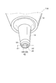
- FIG. 3 is a schematic enlarged view illustrating the tip of the bonding capillary according to this embodiment.
- FIG. 3 is a perspective view of the tip of the capillary shown in FIG. 2 as viewed obliquely from below.
- the main body 10 includes a first pressing surface 51 and a second pressing surface 52 provided at the end in the axial direction.
- the first pressing surface 51 is provided around the insertion hole 20 at the tip of the main body 10.
- the 1st press surface 51 is a part of surface of the bottleneck part 13, for example, is a curved surface shape.
- the second pressing surface 52 is provided between the insertion hole 20 and the first pressing surface 51.
- the second pressing surface 52 is a part of the surface of the bottle neck portion 13 and is a surface continuous with the first pressing surface 51.
- the first pressing surface 51 and the second pressing surface 52 are surfaces that press the wire against the lead frame in wire bonding.
- the first pressing surface 51 is a pressing surface that forms the main bonding
- the second pressing surface 52 is a pressing surface that forms the temporary bonding.
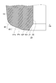
- FIG. 4A, FIG. 4B, and FIG. 5 are schematic cross-sectional views illustrating the tip of the bonding capillary according to this embodiment.
- FIG. 4A shows a cross section taken along line A1-A2 shown in FIG. That is, FIG. 4A shows a cross section in a plane parallel to the axial direction Da.
- FIG. 4B illustrates an enlarged cross section of the region B illustrated in FIG.
- the insertion hole 20 includes a tapered hole 21 and a straight hole 22.
- the tapered hole 21 is provided on the distal end side of the straight hole 22 and is connected to the straight hole 22.
- the diameter of the tapered hole 21 increases toward the tip side.
- the first pressing surface 51 has a first inclined surface 51 s provided around the insertion hole 20.
- the first inclined surface 51s is inclined with respect to the axial direction Da and the radial direction (a direction perpendicular to the axial direction Da). Then, the diameter of the first inclined surface 51 s becomes smaller toward the distal end side of the main body portion 10. That is, the distance between the central axis 20a of the insertion hole 20 and the first inclined surface 51s becomes shorter along the tip direction.
- the cross-sectional shape of the first inclined surface 51 s in FIG. 4B includes a curved portion, but may be a linear shape or may be configured by a straight line and a curved line.
- the second pressing surface 52 has a tapered surface 52t and a second inclined surface 52f.
- the tapered surface 52t is provided around the insertion hole 20 between the first inclined surface 51s and the insertion hole 20.
- the tapered surface 52 t is a portion of the second pressing surface 52 that faces the tapered hole 21.
- the tapered surface 52t has a tapered shape that widens toward the tip. That is, the distance between the central axis 20a of the insertion hole 20 and the tapered surface 52t is longer along the distal direction.
- the second inclined surface 52f is provided between the tapered surface 52t and the first inclined surface 51s.
- the second inclined surface 52f is a surface that is continuous with the tapered surface 52t and the first inclined surface 51s, and is located on the most distal end side of the bottle neck portion 13.
- the second inclined surface 52f may be slightly inclined from a plane perpendicular to the axial direction Da ( ⁇ 1> 0).
- the surface of the first pressing surface 51 is formed to be rougher than the surface of the second pressing surface 52. That is, the second inclined surface 52f and the tapered surface 52t are smoother than the first inclined surface 51s.
- the uneven shape on the surface of the second inclined surface 52f is smaller than the uneven shape on the surface of the first inclined surface 51s
- the uneven shape on the surface of the tapered surface 52t is smaller than the uneven shape on the surface of the first inclined surface 51s. Is also small.
- the root mean square slope (R ⁇ q) of the roughness curve element of the second inclined surface 52f is smaller than the root mean square slope (R ⁇ q) of the roughness curve element of the first slope 51s.
- the root mean square slope (R ⁇ q) of the roughness curve element of the tapered surface 52t is smaller than the root mean square slope (R ⁇ q) of the roughness curve element of the first slope 51s.
- the root mean square slope (R ⁇ q) of the roughness curve element represents the irregular shape of the surface and is a parameter corresponding to the magnitude of the irregularity slope.
- FIG. 5 illustrates a cross-section obtained by further enlarging FIG.
- the diameter of the second inclined surface 52 f is smaller toward the tip side of the main body 10. That is, the distance between the central axis 20a of the insertion hole 20 and the second inclined surface 52f is shortened along the distal direction.
- the intersection (intersection line) between the tapered surface 52 t and the second inclined surface 52 f is located at the foremost end of the main body 10.
- the angle ⁇ 1 is smaller than the angle ⁇ 2.
- the angle ⁇ 1 is an angle formed by the plane P1 perpendicular to the axial direction Da and the second inclined surface 52f.
- the angle ⁇ 2 is an angle formed by the plane P1 perpendicular to the axial direction Da and the first inclined surface. It is desirable that the angle ⁇ 1 is not less than 0 degrees and not more than 11 degrees.
- the angle ⁇ 2 is preferably, for example, 2 degrees or more and 45 degrees or less.
- FIG. 6 is a schematic cross-sectional view illustrating the state of wire bonding.
- the wire BW inserted through the insertion hole 20 of the capillary 110 is first bonded to an electrode or the like of a semiconductor element (not shown). Thereafter, the capillary 110 is drawn around the lead 200 in a predetermined orbit to form a loop on the wire BW.
- second bonding for bonding the wire BW to the lead 200 is performed.
- FIG. 6 shows a second bonding state in which the lead 200 of the lead frame and the wire BW are joined.
- the lead frame used in this embodiment is, for example, a rough lead frame. That is, on the surface of the lead 200, a thick Ni plating layer or the like subjected to roughening treatment is provided.
- the thickness of the plating layer is, for example, about 20 ⁇ m.
- copper is used as the material of the wire BW.
- the capillary 110 is pressed onto the lead 200. Accordingly, the wire BW is sandwiched between the first pressing surface 51 (first inclined surface 51s) and the lead 200. Further, the wire BW is sandwiched between the second pressing surface 52 and the lead 200.
- the distance between the first inclined surface 51 s and the lead 200 becomes narrower along the direction toward the inside of the capillary 110. . Therefore, the thickness of the wire BW sandwiched between the first inclined surface 51 s and the lead 200 is reduced along the direction toward the inside of the capillary 110.
- the thickness of the wire BW is the thinnest between the second inclined surface 52f and the lead 200. Since the taper surface 52t has a taper shape, the interval between the taper surface 52t and the lead 200 becomes wider along the direction toward the inside of the capillary 110. Accordingly, the thickness of the wire BW sandwiched between the tapered surface 52t and the lead 200 increases along the direction toward the inside of the capillary 110.
- ultrasonic waves are applied to the capillary 110 with the wire BW sandwiched between the capillary 110 and the lead 200.
- the wire BW is crimped to the lead 200.
- a main joint (stitch bond portion SB) is formed between the first pressing surface 51 (first inclined surface 51s) and the lead 200, and the second pressing surface 52 (second inclined surface 52f and A temporary joint portion (tail bond portion TB) is formed between the tapered surface 52t) and the lead 200.
- the capillary 110 After crimping the wire BW, the capillary 110 is raised with the wire BW clamped by the capillary 110. As a result, the wire BW is cut off from the tail bond portion TB. For example, since the intersection (intersection line) between the second inclined surface 52f and the tapered surface 52t is formed relatively sharply, the wire BW is divided at a portion pressed by this intersection.
- FIG. 7A and 7B are photographic images illustrating the bonding wire and the lead 200.
- the wire BW is joined to the lead 200 and separated from the tail bond portion TB.
- FIG. 7B illustrates a defect that occurs when the wire breakability deteriorates.
- a part of the bonding portion for example, the stitch bond portion SB
- peeling or fishtail a part of the bonding portion
- the first inclined surface 51s having a rough surface state is provided at the tip of the capillary 110.
- the wire BW can be efficiently pressed against the lead 200 by the first inclined surface 51s. Therefore, the bonding strength of the stitch bond portion SB can be ensured.
- a smooth second inclined surface 52f and a tapered surface 52t are provided at the tip of the capillary 110.
- the wire BW is pressed against the lead 200 by the second inclined surface 52f and the tapered surface 52t. For this reason, compared with the case where the 2nd inclined surface 52f is not provided, the contact area of the capillary 110 and the wire BW increases, and it can improve the joint strength of the tail bond part TB.
- the wire BW is pressed down by the rough first inclined surface 51s, and the sliding between the wire BW and the capillary 110 is promoted by the smooth second inclined surface 52f. Thereby, the parting property of a wire can be improved.
- FIG. 8A and FIG. 8B are schematic views for explaining wire division by the bonding capillary according to the embodiment.
- FIG. 8A is a conceptual diagram for explaining the action of the capillary when the wire is divided.
- FIG. 8A shows an enlarged cross section of a region where the capillary 110 and the wire BW are in contact with each other in the vicinity of the boundary between the first inclined surface 51s and the second inclined surface 52f. This region corresponds to an appropriate position for dividing the wire BW, that is, a portion where the wire BW is thinnest.
- the left side of the capillary 110 in the figure corresponds to the first inclined surface 51s having a large R ⁇ q (root mean square inclination), and the right side corresponds to the second inclined surface 52f having a small R ⁇ q. It is shown that the slope of the unevenness with respect to the wire surface is larger when R ⁇ q representing the uneven shape is larger. That is, for example, the angle ⁇ 3 shown in FIG. 8A is larger than the angle ⁇ 4.
- vector F2 can be decomposed into vector F21 and vector F22.
- the vector F21 is a vector in a direction along the surface of the second inclined surface 52f.
- the vector F22 is a vector in a direction perpendicular to the vector F21.
- the vector F21 increases as R ⁇ q decreases. That is, when R ⁇ q is small, the component deviating upward is increased as in the vector F21. For this reason, the force transmitted from the surface of the capillary 110 to the wire BW is reduced. Accordingly, the tensile force FT2 generated on the wire BW by the second inclined surface 52f having a small R ⁇ q is relatively small.
- the vector F1 can be decomposed into a vector F11 and a vector F12.
- the vector F11 is a vector in a direction along the surface of the first inclined surface 51s.
- the vector F12 is a vector in a direction perpendicular to the vector F12.
- the tensile force FT1 generated in the wire BW by the first inclined surface 51s having a large R ⁇ q is large.
- the first inclined surface 51s having a large R ⁇ q and the second inclined surface 52f having a small R ⁇ q are provided adjacent to each other. For this reason, a large stress is generated due to the difference between the tensile force FT1 and the tensile force FT2 at an appropriate position for dividing the wire located near the boundary between the first inclined surface 51s and the second inclined surface 52f. For this reason, as shown in FIG. 8A, generation of a microcrack is promoted near the boundary between the first inclined surface 51s and the second inclined surface 52f. And in the micro crack which generate
- the second inclined surface 52 f is provided so as to be substantially parallel to the surface of the lead 200. Further, since R ⁇ q of the second inclined surface 52f is small, as shown in FIG. 8A, the tip angle ⁇ 5 of the convex portion of the second inclined surface 52f is large. For example, the tip angle ⁇ 5 is larger than the tip angle ⁇ 6 of the convex portion of the first inclined surface 51s. For this reason, concentration of stress at the tip of the capillary 110 can be suppressed, and wear of the capillary can be suppressed.
- the irregular shape (R ⁇ q, Rz, Rc, Rsk, Rp, Rku, etc.) on the capillary surface is calculated based on JIS B 0601-2001.
- a roughness curve was measured under the following conditions.
- the uneven shape is calculated from the measurement result of the roughness curve.
- Measuring instrument Laser microscope (Olympus, OLS4000) Measurement magnification: 50 times Evaluation length: 125 ⁇ m to 400 ⁇ m Cut-off (phase compensation type high-pass filter) ⁇ c: 25 ⁇ m
- FIG. 9 is a diagram illustrating an evaluation result of the bonding capillary.
- R ⁇ q (°) of the roughness curve element of the first inclined surface 51s shows a combination of the root mean square slope R ⁇ q (°) of the roughness curve element of the first inclined surface 51s and the root mean square slope R ⁇ q (°) of the roughness curve element of the second slope 52f. Shows the evaluation results of different examples (Comparative Examples 1 to 4, Examples 1 to 8). In this evaluation, R ⁇ q of the first inclined surface 51s was set to 5.4 ° to 12.4 °. In addition, R ⁇ q of the second inclined surface 52f was set to 1.8 ° to 13.4 °. Note that R ⁇ q of the tapered surface 52t is the same as R ⁇ q of the second inclined surface 52f.
- the root mean square slope R ⁇ q of the roughness curve element can be calculated based on the following equation (1).
- l is the reference length
- Z (x) is the height value in the roughness curve.
- FIG. 9 shows the evaluation result of the occurrence frequency of peeling failure.
- the item “Peeling occurrence frequency” represents the occurrence frequency of peeling after the second bonding.
- the number of samples was 32 or 128 for each of Comparative Examples 1 to 4 and Examples 1 to 8 shown in FIG.
- “X” represents that peeling occurred in 32 samples. That is, “x” means that the occurrence frequency of peeling is 1/32 or more.
- “ ⁇ ” indicates that peeling did not occur in 32 samples, but peeling occurred when the number of samples was increased.
- “ ⁇ ” means that the occurrence frequency of peeling is 1/127 or more and less than 1/32.
- “ ⁇ ” represents that no peeling occurred in 128 samples. That is, “ ⁇ ” means that the occurrence frequency of peeling is less than 1/128.
- the peeling is performed.
- the frequency of occurrence is low.
- the R ⁇ q of the first inclined surface 51s is 11 ° or more and the R ⁇ q of the second inclined surface 52f is 2 ° or less, further peeling is performed. Occurrence can be suppressed. As described with reference to FIGS. 8A and 8B, this is considered to be due to the large tensile force caused by the first inclined surface 51s and the small tensile force caused by the second inclined surface 52f. .
- the occurrence of a microcrack is promoted at an appropriate position for dividing the wire, and the deformation mode of the microcrack becomes mode I (opening mode), and the crack progresses. Thereby, the parting property of a wire improves.
- R ⁇ q of the first inclined surface 51s is set to 11 ° or more and R ⁇ q of the second inclined surface 52f is set to 2 ° or less, the first inclined surface 51s even if the bonding capillary is worn. It is easy to keep the difference between R ⁇ q of R2q and R ⁇ q of the second inclined surface 52f above a certain level. For this reason, the stress which arises in the wire BW by the difference in tensile force can be maintained.
- FIG. 10 is a diagram illustrating an evaluation result of the bonding capillary.
- FIG. 10 is a diagram illustrating an evaluation result when the width W1 of the second inclined surface 52f is changed with respect to the tip diameter T of the capillary 110.
- FIG. 10 is a diagram illustrating an evaluation result when the width W1 of the second inclined surface 52f is changed with respect to the tip diameter T of the capillary 110.
- the width W1 of the second inclined surface 52f is the width of the second inclined surface 52f when the capillary 110 is viewed along the axial direction.
- the shape of the second inclined surface 52f is an annular shape having an outer diameter D1 and an inner diameter D2 when viewed along the axial direction (see FIGS. 4A and 4B).
- the width W1 is 1 ⁇ 2 times the difference between the outer diameter D1 and the inner diameter D2.
- an average value in the circumferential direction may be used as the inner diameter D2.
- the tip diameter T of the capillary 110 is the outer diameter of the annular first inclined surface 51s (first pressing surface 51) when viewed along the axial direction.
- the outer diameter of the first inclined surface 51s is an imaginary circle Cr formed by intersecting an extended surface of the outer peripheral surface of the bottle neck portion 13 and a plane including the second inclined surface 52f. (See FIG. 4 (a) and FIG. 4 (b)).
- FIG. 10 shows the evaluation result of the occurrence frequency of peeling failure.
- the item “Peeling occurrence frequency” represents the occurrence frequency of peeling after the second bonding.
- the number of samples is 32 for each ratio of the width W1 to the tip diameter T shown in FIG. “ ⁇ ” indicates that no peeling occurred. That is, “ ⁇ ” means that the peeling occurrence rate is less than 1/32.
- “X” indicates that peeling has occurred. That is, “x” means that the occurrence rate of peeling is 1/32 or more.
- a wire having a diameter of 25 ⁇ m was used.
- the tip diameter T of the capillary 110 was set to 75 ⁇ m.
- the width W1 of the second inclined surface 52f is preferably 2% or more and 8% or less of the tip diameter T.
- the ratio of the width W1 to the tip diameter T is larger than 8%, it becomes difficult to generate sufficient stress at the tip of the capillary 110, and the bonding strength is lowered.
- the ratio of the width W1 to the tip diameter T is less than 2%, the stress generated at the tip of the capillary 110 becomes large, and the tip of the capillary 110 is easily worn.
- the ratio of the width W1 to the tip diameter T is 2% or more and 8% or less, sufficient bonding strength can be obtained while suppressing wear of the capillary 110.
- FIG. 11 is a diagram illustrating an evaluation result of the bonding capillary.
- FIG. 11 shows the evaluation results of examples (Comparative Examples 5 to 9, Examples 9 to 14) in which the combinations of the maximum height Rz of the first inclined surface 51s and the maximum height Rz of the second inclined surface 52f are different. Show.
- the maximum height Rz of the tapered surface 52t is the same as the maximum height Rz of the second inclined surface 52f.
- the maximum height Rz is the sum of the maximum value of the peak height and the maximum value of the valley depth in the reference length.
- FIG. 11 shows the evaluation result of the frequency of occurrence of peeling failure.
- the item “Peeling occurrence frequency” represents the occurrence frequency of peeling after the second bonding, as described in FIG. That is, in each example (each condition), “ ⁇ ” represents that no peeling occurred in 128 samples, “ ⁇ ” represents that no peeling occurred in 32 samples, and “ ⁇ ” "" Indicates that peeling occurred in 32 samples.
- the maximum height Rz of the first inclined surface 51s is 0.2 ⁇ m or more, and the maximum height Rz of the second inclined surface 52f is 0.16 ⁇ m or less.
- the peeling occurrence frequency is “ ⁇ ”.
- the maximum height Rz of the first inclined surface 51s is 0.3 ⁇ m or more, and the maximum height Rz of the second inclined surface 52f is 0.10 ⁇ m or less.
- the peeling occurrence frequency is “ ⁇ ⁇ ”.
- the wire BW can be suppressed by the first inclined surface 51 s, so that sufficient bonding strength can be obtained. Further, since the maximum height Rz of the second inclined surface 52f and the maximum height Rz of the tapered surface 52t are each 0.16 ⁇ m or less, sliding between the wire BW and the bonding capillary is promoted. Thereby, the parting property of the wire BW can be improved. As described above, occurrence of peeling failure can be suppressed.
- the maximum height Rz of the first inclined surface 51s is 0.3 ⁇ m or more and the maximum height Rz of the second inclined surface 52f is 0.10 ⁇ m or less, even if the capillary is worn, The maximum height Rz can be kept above a certain level. Thereby, in the same manner as described above, the wire breakability can be improved.
- FIG. 12 is a diagram illustrating an evaluation result of the bonding capillary.
- FIG. 12 shows an evaluation result when the angle ⁇ 1 (see FIG. 5) of the second inclined surface 52f is changed.
- the angle ⁇ 1 is set to 0.5 degrees or more and 17 degrees or less.
- the angle ⁇ 2 of the first inclined surface was 20 degrees, and the width W1 of the second inclined surface 52f was 4 ⁇ m.
- the item “Peeling occurrence frequency” in FIG. 12 represents the occurrence frequency of peeling after the second bonding, as described in FIG. That is, when the number of samples of each condition of the angle ⁇ 1 is evaluated as 32, “ ⁇ ” indicates that peeling has not occurred, and “x” indicates that peeling has occurred.
- the angle ⁇ 1 is preferably smaller than the angle ⁇ 2.
- the 2nd inclined surface 52f can hold down a wire at the time of temporary joining, the joining strength of a tail bond part can be improved.
- no peeling failure occurs when the angle ⁇ 1 is not less than 0.5 degrees and not more than 11 degrees. If the angle ⁇ 1 is 11 degrees or less, the wire can be pressed by the second inclined surface 52f during temporary bonding. Thereby, it is possible to generate a stress capable of obtaining a sufficient bonding strength of the tail bond portion. Therefore, occurrence of peeling failure can be suppressed.
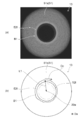
- FIG. 13A and FIG. 13B are diagrams illustrating the bonding capillary according to the embodiment.
- FIG. 13A and FIG. 13B show a state when the tips (the first pressing surface 51 and the second pressing surface 52) of the bonding capillary 110 are viewed along the axial direction.
- FIG. 13A is a laser microscope image
- FIG. 13B is a plan view corresponding to FIG.
- the boundary B1 between the first inclined surface 51s and the second inclined surface 52f is, for example, substantially circular with the central axis 20a as the center, as shown in FIG. 13B.
- the shape of the boundary B1 is not a perfect circle (or an ellipse) but a saw shape (sawtooth shape, jagged shape). That is, the distance L1 from the central axis 20a to the point on the boundary B1 changes along the circumferential direction Dc.
- the points on the boundary B1 vary in a range of, for example, 1.5 ⁇ m or less from a circle (or an ellipse) obtained by approximation (or smoothing) of the shape of the boundary B1.
- the wire BW has a large stress from the capillary near the boundary B1 between the first inclined surface 51s and the second inclined surface 52f. Receive. Then, as shown in FIGS. 13A and 13B, the boundary B1 has a saw shape, so that the boundary B1 comes into further contact with the wire BW. That is, the contact portion between the boundary B1 and the wire BW that causes a large stress on the wire BW increases. Thereby, for example, when an ultrasonic wave is applied, stress is repeatedly generated in the wire BW. As described above, microcracks are easily generated, and the wire breakability can be improved.
- FIG. 14 is a diagram illustrating an evaluation result of the bonding capillary.
- FIG. 14 shows the determination results of the bonding strength in examples (Comparative Examples 10 to 12, Examples 15 to 20) having different uneven shapes on the first inclined surface 51s.
- the average height Rc of the roughness curve element, the skewness Rsk of the roughness curve, and the maximum peak height Rp of the roughness curve are changed as the uneven shape of the first inclined surface 51s.
- the average height Rc is obtained by the following equation (2).
- the skewness Rsk is obtained by the following equation (3).
- Equation (2) m is the number of contour curve elements, and Zti is the average height of the contour curve elements.
- Zq is the root mean square height, and Zn is the height value in the roughness curve.
- the maximum peak height Rp is the maximum height in the roughness curve.
- Skewness Rsk represents the symmetry between the concavo-convex peaks (convex) and valleys (concave). If the uneven shape is a sine distribution, the skewness Rsk is zero. When the skewness Rsk is negative, it means that the area of the peak (convex) is larger than the area of the valley (concave) (the sharpness of the convex part is smaller than the sharpness of the concave part).
- FIG. 14 shows the average height Rc, skewness Rsk, and maximum mountain height Rp in each example (each condition).
- the bonding strength was determined based on the process capability index Cpk of the bonding strength.
- Cpk (Ave ⁇ 3gf) / 3 ⁇ .
- the bonding strength is a strength in a pull test in the second bond.
- the number of samples is 30.
- the joint strength Cpk in wire bonding is required to be 1.67 or more.
- “Junction strength determination” indicates “OK” when Cpk is 1.67 or more, and “NG” when Cpk is less than 1.67.
- each combination of Rc, Rsk and Rp after initial wire bonding was performed 500,000 times, after wire bonding was performed 1,000,000 times, and after wire bonding was performed 1.5 million times Went.
- Example 15 to 20 and Comparative Examples 10 to 12 the initial bond strength determination is all “OK”. After 500,000 times of wire bonding, Examples 15 to 20 are “OK”, but Comparative Examples 10 to 12 are all “NG”. After 1 million times of wire bonding, Examples 15 to 17, 19 and 20 are “OK”, and Example 18 and Comparative Examples 10 to 12 are “NG”. After 1.5 million wire bondings, Examples 19 and 20 are “OK”, and Examples 15 to 18 and Comparative Examples 10 to 12 are “NG”.
- the skewness Rsk of the first inclined surface 51s is about ⁇ 1.2 or more and ⁇ 0.3 or less, and the average height Rc of the first inclined surface 51s is 0.06 ⁇ m or more and 0.3 ⁇ m.
- the following is preferable. If the average height Rc is 0.06 ⁇ m or more, the gripping force is small, and in particular, when a copper wire BW is used, sufficient bonding strength cannot be obtained. On the other hand, when the average height Rc exceeds 0.3 ⁇ m, it becomes difficult to form irregularities having a skewness Rsk of ⁇ 0.3 or less.
- the skewness Rsk of the tip surface 50 is about ⁇ 1.2 or more and ⁇ 0.43 or less, and the average height Rc of the tip surface 50 is 0.16 ⁇ m or more and 0.3 ⁇ m or less.
- the initial bonding strength can be maintained even after 1,500,000 times from the initial bonding.
- the maximum peak height Rp of the first inclined surface 51s is preferably 0.9 times or less (Rp / Rc ⁇ 0.9) of the average height Rc.
- Rp / Rc can be 0.5 times or more.
- Rp / Rc exceeds 0.9, it becomes difficult to maintain the initial bonding strength for a long period of time.
- Rp / Rc is 0.9 or less, the shape change due to wear during use is small, and the initial bonding strength is maintained for a long time.
- FIG. 15 is a diagram illustrating an evaluation result of the bonding capillary.
- FIG. 15 shows evaluation results of examples (Comparative Examples 13 and 14, Examples 21 to 23) having different kurtosis Rku of the roughness curve of the second inclined surface 52f.
- the kurtosis Rku is determined by the following equation (4).
- Rq is the root mean square height of the roughness curve
- lr is the reference length
- Z (x) is the roughness curve (peak height). That is, kurtosis (Rku) is obtained by dividing the fourth average of Z (x) in the reference length by the fourth power of the root mean square.
- the kurtosis Rku represents the “sharpness” of the roughness curve. The unevenness of the surface is sharper as Rku is larger.
- the item “Peeling frequency” in FIG. 15 represents the occurrence frequency of peeling after the second bonding, as described in FIG. That is, when the number of samples in each example was evaluated as 32, “ ⁇ ” represents that peeling did not occur, and “x” represents that peeling occurred.
- the kurtosis Rku of the second inclined surface 52f is preferably 5.0 or less, and more preferably 3.0 or less.
- the kurtosis Rku of the second inclined surface 52f is 5 ⁇ m or less, sliding of the wire BW and the second inclined surface 52f is promoted when the wire is divided. Thereby, the parting property of a wire can be improved.
- a bonding capillary that can improve the bonding strength, improve the breakability of the wire, and suppress wear.
Landscapes
- Wire Bonding (AREA)
Abstract
Description
図1は、本実施形態に係るボンディングキャピラリを例示する模式図である。
図2は、本実施形態に係るボンディングキャピラリの先端形状を例示する模式的拡大図である。
図1には、ボンディングキャピラリ110の全体が表されている。図2には、図1に示す領域Aを拡大した図が表されている。
図3に表したように、本体部10は、軸方向における端部に設けられた、第1の押圧面51および第2の押圧面52を有する。
図4(a)、図4(b)及び図5は、本実施形態に係るボンディングキャピラリの先端を例示する模式的断面図である。
図4(a)は、図3に表したA1-A2線における断面を示している。すなわち、図4(a)は、軸方向Daに平行な平面における断面を示す。図4(b)は、図4(a)に表した領域Bを拡大した断面を例示している。
テーパ面52tは、第1の傾斜面51sと挿通孔20との間において、挿通孔20の周囲に設けられている。テーパ面52tは、第2の押圧面52のうち、テーパ状孔21に面した部分である。テーパ面52tは、先端に向かって広がるテーパ形状を有する。すなわち、挿通孔20の中心軸20aとテーパ面52tとの間の距離は、先端方向に沿って長くなっている。
図6は、ワイヤボンディングの状態を例示する模式的断面図である。
キャピラリ110の挿通孔20に挿通されたワイヤBWは、図示しない半導体素子の電極等にファーストボンディングされる。その後、キャピラリ110を所定の軌道でリード200上まで引き回してワイヤBWにループが形成される。次に、ワイヤBWをリード200に接合するセカンドボンディングが行われる。図6では、リードフレームのリード200とワイヤBWとを接合するセカンドボンディングの状態が表されている。
図8(a)は、ワイヤを分断する際における、キャピラリの作用を説明する概念図である。図8(a)には、第1の傾斜面51sと第2の傾斜面52fとの境界付近において、キャピラリ110とワイヤBWとが接している領域の拡大断面を示している。この領域は、ワイヤBWのワイヤ分断適所、すなわち最もワイヤBWが薄い部分に相当する。
測定機器:レーザ顕微鏡(オリンパス社製、OLS4000)
測定倍率:50倍
評価長さ:125μm~400μm
カットオフ(位相補償形高域フィルタ)λc:25μm
図9は、ボンディングキャピラリの評価結果を例示する図である。
図9は、第1の傾斜面51sの粗さ曲線要素の二乗平均平方根傾斜RΔq(°)と、第2の傾斜面52fの粗さ曲線要素の二乗平均平方根傾斜RΔq(°)と、の組合せが異なる例(比較例1~4、実施例1~8)の評価結果を示す。本評価では、第1の傾斜面51sのRΔqを5.4°~12.4°とした。また、第2の傾斜面52fのRΔqを1.8°~13.4°とした。なお、テーパ面52tのRΔqは、第2の傾斜面52fのRΔqと同じとした。

図9は、ピーリング不良の発生頻度の評価結果を示す。ここで、「Peeling発生頻度」の項目は、セカンドボンディング後のピーリングの発生頻度を表す。図9に示した比較例1~4及び実施例1~8のそれぞれについて、サンプル数を32又は128とした。「×」は、32個のサンプル中で、ピーリングが発生したことを表す。すなわち、「×」は、ピーリングの発生頻度が1/32以上であることを意味する。「○」は、32個のサンプル中ではピーリングが発生しなかったが、サンプル数を増やすとピーリングが発生したことを表す。「○」は、ピーリングの発生頻度が1/127以上1/32未満であることを意味する。「◎」は、128個のサンプル中で、ピーリングが発生しなかったことを表す。すなわち「◎」は、ピーリングの発生頻度が1/128未満であることを意味する。
図10は、キャピラリ110の先端径Tに対する、第2の傾斜面52fの幅W1の変化させた場合の評価結果を示す図である。
図11は、第1の傾斜面51sの最大高さRz、および第2の傾斜面52fの最大高さRzの組合せが異なる例(比較例5~9、実施例9~14)の評価結果を示す。なお、テーパ面52tの最大高さRzは、第2の傾斜面52fの最大高さRzと同じとした。最大高さRzは、基準長さにおける山高さの最大値と谷深さの最大値との和である。
図12は、第2の傾斜面52fの角度θ1(図5を参照)を変化させた場合の評価結果を示す。本評価では、角度θ1を0.5度以上17度以下とした。また、第1の傾斜面の角度θ2を20度とし、第2の傾斜面52fの幅W1を4μmとした。
図13(a)及び図13(b)は、ボンディングキャピラリ110の先端(第1の押圧面51及び第2の押圧面52)を、軸方向に沿ってみたときの様子を表す。図13(a)は、レーザ顕微鏡像であり、図13(b)は、図13(a)に対応する平面図である。
図14は、第1の傾斜面51sの凹凸形状が異なる例(比較例10~12、実施例15~20)における、接合強度の判定結果を示す。この評価では、第1の傾斜面51sの凹凸形状として、粗さ曲線要素の平均高さRc、粗さ曲線のスキューネスRsk、及び粗さ曲線の最大山高さRpを変化させている。


図15は、第2の傾斜面52fの粗さ曲線のクルトシスRkuが異なる例(比較例13、14、実施例21~23)の評価結果を示す。クルトシスRkuは、以下の式(4)によって求められる。

Rqは、粗さ曲線の二乗平均平方根高さであり、lrは、基準長さであり、Z(x)は、粗さ曲線(山の高さ)である。すなわち、クルトシス(Rku)とは、基準長さにおけるZ(x)の四乗平均を二乗平均平方根の四乗で割ったものである。クルトシスRkuは、粗さ曲線の「尖り度」を表している。面の凹凸は、Rkuが大きい程尖っている。
11 円筒部、
12 円錐部、
13 ボトルネック部、
20 挿通孔、
20a 中心軸、
21 テーパ状孔、
22 直状孔、
51 第1の押圧面、
51s 第1の傾斜面、
52 第2の押圧面、
52f 第2の傾斜面、
52t テーパ面、
110 ボンディングキャピラリ、
200 リード、
A、B、C、D 領域、
B1 境界、
F1、F11、F12、F2、F21、F22 ベクトル、
BW ワイヤ、
Cr 仮想円、
Da 軸方向、
Dc 周方向、
D1 外径、
D2 内径、
P1 面、
SB スティッチボンド部、
TB テールボンド部、
T 先端径、
W1 幅、
θ1~6 角度
Claims (11)
- ワイヤが挿通される挿通孔と、
前記ワイヤを押圧する第1の押圧面であって、前記挿通孔の周囲に設けられ前記挿通孔が延在する軸方向に対して傾斜した第1の傾斜面を有する第1の押圧面と、
前記ワイヤを押圧する第2の押圧面であって、前記第1の傾斜面と前記挿通孔との間に設けられテーパ形状を有するテーパ面と、前記テーパ面と前記第1の傾斜面との間に設けられた第2の傾斜面と、を有する第2の押圧面と、
を有する本体部を備え、
前記第2の傾斜面の粗さ曲線要素の二乗平均平方根傾斜は、前記第1の傾斜面の粗さ曲線要素の二乗平均平方根傾斜よりも小さいことを特徴とするボンディングキャピラリ。 - 前記第1の傾斜面の粗さ曲線要素の二乗平均平方根傾斜は、8°以上であり、
前記第2の傾斜面の粗さ曲線要素の二乗平均平方根傾斜は、5°以下であることを特徴とする請求項1に記載のボンディングキャピラリ。 - 前記第1の傾斜面の粗さ曲線要素の二乗平均平方根傾斜は、11°以上であり、
前記第2の傾斜面の粗さ曲線要素の二乗平均平方根傾斜は、2°以下であることを特徴とする請求項1または2に記載のボンディングキャピラリ。 - 前記軸方向に沿ってみたときに、前記第2の傾斜面の幅は、前記第1の押圧面の外径の2%以上8%以下であることを特徴とする請求項1~3のいずれか1つに記載のボンディングキャピラリ。
- 前記第1の傾斜面の最大高さRzは、0.2マイクロメートル以上であり、
前記第2の傾斜面の最大高さRzは、0.16マイクロメートル以下であることを特徴とする請求項1~4のいずれか1つに記載のボンディングキャピラリ。 - 前記第1の傾斜面の最大高さRzは、0.3マイクロメートル以上であり、
前記第2の傾斜面の最大高さRzは、0.10マイクロメートル以下であることを特徴とする請求項1~5のいずれか1つに記載のボンディングキャピラリ。 - 前記軸方向に対して垂直な面と前記第2の傾斜面とがなす角度は、前記軸方向に対して垂直な前記面と前記第1の傾斜面とがなす角度よりも小さいことを特徴とする請求項1~6のいずれか1つに記載のボンディングキャピラリ。
- 前記軸方向に対して垂直な面と前記第2の傾斜面とがなす角度は、11度以下であることを特徴とする請求項1~7のいずれか1つに記載のボンディングキャピラリ。
- 前記第1の傾斜面と前記第2の傾斜面との境界は、前記軸方向に沿ってみたときに、鋸形状であることを特徴とする請求項1~8のいずれか1つに記載のボンディングキャピラリ。
- 前記第1の傾斜面のスキューネスは、-0.3以下であり、
前記第1の傾斜面の平均高さは、0.06マイクロメートル以上0.3マイクロメートル以下であることを特徴とする請求項1~9のいずれか1つに記載のボンディングキャピラリ。 - 前記第2の傾斜面のクルトシスは、5.0以下であることを特徴とする請求項1~10のいずれか1つに記載のボンディングキャピラリ。
Priority Applications (3)
| Application Number | Priority Date | Filing Date | Title |
|---|---|---|---|
| CN201680038201.8A CN107710394B (zh) | 2015-07-03 | 2016-07-01 | 焊接劈刀 |
| KR1020177037004A KR101907906B1 (ko) | 2015-07-03 | 2016-07-01 | 본딩 캐필러리 |
| PH12017502415A PH12017502415B1 (en) | 2015-07-03 | 2017-12-22 | Bonding capillary |
Applications Claiming Priority (4)
| Application Number | Priority Date | Filing Date | Title |
|---|---|---|---|
| JP2015134649 | 2015-07-03 | ||
| JP2015-134649 | 2015-07-03 | ||
| JP2016018954A JP6064308B2 (ja) | 2015-07-03 | 2016-02-03 | ボンディングキャピラリ |
| JP2016-018954 | 2016-02-03 |
Publications (1)
| Publication Number | Publication Date |
|---|---|
| WO2017006880A1 true WO2017006880A1 (ja) | 2017-01-12 |
Family
ID=57685762
Family Applications (1)
| Application Number | Title | Priority Date | Filing Date |
|---|---|---|---|
| PCT/JP2016/069699 Ceased WO2017006880A1 (ja) | 2015-07-03 | 2016-07-01 | ボンディングキャピラリ |
Country Status (1)
| Country | Link |
|---|---|
| WO (1) | WO2017006880A1 (ja) |
Cited By (1)
| Publication number | Priority date | Publication date | Assignee | Title |
|---|---|---|---|---|
| CN119387860A (zh) * | 2024-12-18 | 2025-02-07 | 苏州芯合半导体材料有限公司 | 一种陶瓷劈刀及其表面处理方法 |
Citations (3)
| Publication number | Priority date | Publication date | Assignee | Title |
|---|---|---|---|---|
| JPH0274051A (ja) * | 1988-09-09 | 1990-03-14 | Fujitsu Ltd | 半導体ウエハ表面のヘイズ評価法 |
| US5662261A (en) * | 1995-04-11 | 1997-09-02 | Micron Technology, Inc. | Wire bonding capillary |
| JP2014082450A (ja) * | 2012-09-26 | 2014-05-08 | Toto Ltd | ボンディングキャピラリ |
-
2016
- 2016-07-01 WO PCT/JP2016/069699 patent/WO2017006880A1/ja not_active Ceased
Patent Citations (3)
| Publication number | Priority date | Publication date | Assignee | Title |
|---|---|---|---|---|
| JPH0274051A (ja) * | 1988-09-09 | 1990-03-14 | Fujitsu Ltd | 半導体ウエハ表面のヘイズ評価法 |
| US5662261A (en) * | 1995-04-11 | 1997-09-02 | Micron Technology, Inc. | Wire bonding capillary |
| JP2014082450A (ja) * | 2012-09-26 | 2014-05-08 | Toto Ltd | ボンディングキャピラリ |
Cited By (1)
| Publication number | Priority date | Publication date | Assignee | Title |
|---|---|---|---|---|
| CN119387860A (zh) * | 2024-12-18 | 2025-02-07 | 苏州芯合半导体材料有限公司 | 一种陶瓷劈刀及其表面处理方法 |
Similar Documents
| Publication | Publication Date | Title |
|---|---|---|
| JP6064308B2 (ja) | ボンディングキャピラリ | |
| JP5510691B2 (ja) | ボンディングキャピラリ | |
| JP5303643B2 (ja) | 超音波接合用ツール、超音波接合用ツールの製造方法、超音波接合方法及び超音波接合装置 | |
| CN107042359B (zh) | 摩擦搅拌接合方法及接合体 | |
| JP7359245B2 (ja) | 回転ツール及び接合方法 | |
| KR101482597B1 (ko) | 본딩 캐필러리 | |
| US11707773B2 (en) | Method for manufacturing clad steel pipe | |
| CN105659435B (zh) | 压接端子 | |
| CN103177979A (zh) | 引线键合装置、工具及主体、半导体装置制造及键合方法 | |
| WO2017006880A1 (ja) | ボンディングキャピラリ | |
| JP2006013512A (ja) | ワイヤボンディング用キャピラリ | |
| TWI609437B (zh) | Solder pin | |
| US20240335901A1 (en) | Wedge tool and method of manufacturing semiconductor device | |
| KR20120062813A (ko) | 본딩 캐피러리 | |
| KR101974844B1 (ko) | 본딩 캐필러리 | |
| TWI564569B (zh) | 探針結構及其製造方法 | |
| JP2024178746A (ja) | 測定方法及び剥離方法 | |
| KR20110072892A (ko) | 이종 도체 슬리브 제조방법 | |
| JP2010199199A (ja) | ワイヤボンディング方法及びワイヤボンディング構造 | |
| JP2014007430A (ja) | ボンディングキャピラリー |
Legal Events
| Date | Code | Title | Description |
|---|---|---|---|
| 121 | Ep: the epo has been informed by wipo that ep was designated in this application |
Ref document number: 16821349 Country of ref document: EP Kind code of ref document: A1 |
|
| ENP | Entry into the national phase |
Ref document number: 20177037004 Country of ref document: KR Kind code of ref document: A |
|
| WWE | Wipo information: entry into national phase |
Ref document number: 12017502415 Country of ref document: PH |
|
| NENP | Non-entry into the national phase |
Ref country code: DE |
|
| 122 | Ep: pct application non-entry in european phase |
Ref document number: 16821349 Country of ref document: EP Kind code of ref document: A1 |