WO2017006846A1 - 波力発電装置 - Google Patents
波力発電装置 Download PDFInfo
- Publication number
- WO2017006846A1 WO2017006846A1 PCT/JP2016/069590 JP2016069590W WO2017006846A1 WO 2017006846 A1 WO2017006846 A1 WO 2017006846A1 JP 2016069590 W JP2016069590 W JP 2016069590W WO 2017006846 A1 WO2017006846 A1 WO 2017006846A1
- Authority
- WO
- WIPO (PCT)
- Prior art keywords
- wave
- floor member
- power generation
- generation device
- dissipating
- Prior art date
- Legal status (The legal status is an assumption and is not a legal conclusion. Google has not performed a legal analysis and makes no representation as to the accuracy of the status listed.)
- Ceased
Links
Images


Classifications
-
- F—MECHANICAL ENGINEERING; LIGHTING; HEATING; WEAPONS; BLASTING
- F03—MACHINES OR ENGINES FOR LIQUIDS; WIND, SPRING, OR WEIGHT MOTORS; PRODUCING MECHANICAL POWER OR A REACTIVE PROPULSIVE THRUST, NOT OTHERWISE PROVIDED FOR
- F03B—MACHINES OR ENGINES FOR LIQUIDS
- F03B13/00—Adaptations of machines or engines for special use; Combinations of machines or engines with driving or driven apparatus; Power stations or aggregates
- F03B13/12—Adaptations of machines or engines for special use; Combinations of machines or engines with driving or driven apparatus; Power stations or aggregates characterised by using wave or tide energy
- F03B13/14—Adaptations of machines or engines for special use; Combinations of machines or engines with driving or driven apparatus; Power stations or aggregates characterised by using wave or tide energy using wave energy
- F03B13/16—Adaptations of machines or engines for special use; Combinations of machines or engines with driving or driven apparatus; Power stations or aggregates characterised by using wave or tide energy using wave energy using the relative movement between a wave-operated member, i.e. a "wom" and another member, i.e. a reaction member or "rem"
- F03B13/20—Adaptations of machines or engines for special use; Combinations of machines or engines with driving or driven apparatus; Power stations or aggregates characterised by using wave or tide energy using wave energy using the relative movement between a wave-operated member, i.e. a "wom" and another member, i.e. a reaction member or "rem" wherein both members, i.e. wom and rem are movable relative to the sea bed or shore
-
- F—MECHANICAL ENGINEERING; LIGHTING; HEATING; WEAPONS; BLASTING
- F03—MACHINES OR ENGINES FOR LIQUIDS; WIND, SPRING, OR WEIGHT MOTORS; PRODUCING MECHANICAL POWER OR A REACTIVE PROPULSIVE THRUST, NOT OTHERWISE PROVIDED FOR
- F03B—MACHINES OR ENGINES FOR LIQUIDS
- F03B13/00—Adaptations of machines or engines for special use; Combinations of machines or engines with driving or driven apparatus; Power stations or aggregates
- F03B13/12—Adaptations of machines or engines for special use; Combinations of machines or engines with driving or driven apparatus; Power stations or aggregates characterised by using wave or tide energy
- F03B13/14—Adaptations of machines or engines for special use; Combinations of machines or engines with driving or driven apparatus; Power stations or aggregates characterised by using wave or tide energy using wave energy
- F03B13/22—Adaptations of machines or engines for special use; Combinations of machines or engines with driving or driven apparatus; Power stations or aggregates characterised by using wave or tide energy using wave energy using the flow of water resulting from wave movements to drive a motor or turbine
-
- F—MECHANICAL ENGINEERING; LIGHTING; HEATING; WEAPONS; BLASTING
- F03—MACHINES OR ENGINES FOR LIQUIDS; WIND, SPRING, OR WEIGHT MOTORS; PRODUCING MECHANICAL POWER OR A REACTIVE PROPULSIVE THRUST, NOT OTHERWISE PROVIDED FOR
- F03B—MACHINES OR ENGINES FOR LIQUIDS
- F03B7/00—Water wheels
-
- Y—GENERAL TAGGING OF NEW TECHNOLOGICAL DEVELOPMENTS; GENERAL TAGGING OF CROSS-SECTIONAL TECHNOLOGIES SPANNING OVER SEVERAL SECTIONS OF THE IPC; TECHNICAL SUBJECTS COVERED BY FORMER USPC CROSS-REFERENCE ART COLLECTIONS [XRACs] AND DIGESTS
- Y02—TECHNOLOGIES OR APPLICATIONS FOR MITIGATION OR ADAPTATION AGAINST CLIMATE CHANGE
- Y02E—REDUCTION OF GREENHOUSE GAS [GHG] EMISSIONS, RELATED TO ENERGY GENERATION, TRANSMISSION OR DISTRIBUTION
- Y02E10/00—Energy generation through renewable energy sources
- Y02E10/20—Hydro energy
-
- Y—GENERAL TAGGING OF NEW TECHNOLOGICAL DEVELOPMENTS; GENERAL TAGGING OF CROSS-SECTIONAL TECHNOLOGIES SPANNING OVER SEVERAL SECTIONS OF THE IPC; TECHNICAL SUBJECTS COVERED BY FORMER USPC CROSS-REFERENCE ART COLLECTIONS [XRACs] AND DIGESTS
- Y02—TECHNOLOGIES OR APPLICATIONS FOR MITIGATION OR ADAPTATION AGAINST CLIMATE CHANGE
- Y02E—REDUCTION OF GREENHOUSE GAS [GHG] EMISSIONS, RELATED TO ENERGY GENERATION, TRANSMISSION OR DISTRIBUTION
- Y02E10/00—Energy generation through renewable energy sources
- Y02E10/30—Energy from the sea, e.g. using wave energy or salinity gradient
Definitions
- the present invention relates to a wave power generator.
- Patent Document 1 disclose a conventional wave power generation device.
- the wave power generator is attached to a wave-extinguishing block.
- the wave-dissipating block has a front wall portion and an upper wall portion.
- the front wall portion of the wave-dissipating block has a slit-shaped front opening that extends in the vertical direction when the wave-dissipating block is installed on the quay.
- the front opening communicates the wave-dissipating space formed inside the wave-dissipating block with the outside.
- the wave power generation device includes a plurality of water turbines and a power generation device.
- the water turbine has a shaft portion and a rotary blade portion formed around the shaft portion.
- the shaft portion extends in the vertical direction through the upper wall portion of the wave-dissipating block.
- the rotor blade hangs down in the wave-dissipating space along the front opening.
- the power generation apparatus includes a plurality of hydraulic pumps, a hydraulic oil circulation path, a hydraulic motor, and a generator.
- the hydraulic pump is placed and fixed on the upper wall portion of the wave-dissipating block with the upper end of the shaft portion of the water wheel connected.
- the circulation path communicates a plurality of hydraulic pumps with one hydraulic motor.
- the hydraulic motor is rotated by hydraulic oil supplied and discharged by a plurality of hydraulic pumps.
- the generator is connected to the hydraulic motor, and generates electricity by driving the hydraulic motor. In this wave power generator, when a plurality of water turbines rotate, one hydraulic motor is driven, and the generator generates power. For this reason, this wave power generation device can generate power stably even if the rotation of each turbine varies.
- the wave power generation device of the patent document requires that a water wheel, a hydraulic pump, etc. be individually attached to the wave-dissipating block. For this reason, this wave power generation apparatus requires time and effort to attach to the wave-dissipating block. Moreover, this wave power generation apparatus requires time and effort to remove and attach a water wheel, a hydraulic pump, and the like to the wave-dissipating block even when maintenance is performed.
- the present invention has been made in view of the above-described conventional situation, and an object to be solved is to provide a wave power generation device that can be easily attached to and detached from the wave-dissipating block.
- the wave power generator of the present invention is fixed by placing a fixed floor member on a wave-dissipating block.
- the wave-dissipating block has a front wall portion and an upper wall portion.
- the front wall portion of the wave-dissipating block is formed with a plurality of slit-shaped front openings extending in the vertical direction with the wave-dissipating block being installed on the quay.
- the front opening communicates the wave-dissipating space formed inside the wave-dissipating block with the outside.
- the upper wall of the wave-dissipating block has an upper opening that opens above the wave-dissipating space.
- the wave power generation device includes a fixed floor member, a water wheel, and a power generation device.
- the water turbine is rotatably attached with a shaft portion passing through the fixed floor member. This water turbine is inserted into the wave-dissipating space from the upper opening of the wave-dissipating block.
- the power generator is mounted on a fixed floor member. This power generator generates power by rotating a water wheel.
- the wave power generator of the present invention includes a front plate that hangs down from a fixed floor member.
- the front plate has a slit-like opening that is superimposed on the front opening of the wave-dissipating block.
- the fixed floor member of the wave power generation device of the present invention has waterproofness, and the shaft portion penetrates in a watertight manner and is rotatably mounted. Water flows out from the wave-dissipating space above the fixed floor member. To prevent.
- the wave power generation device of the present invention includes a pair of vertical frames, a connecting frame, and a lower frame.
- the pair of vertical frames hang from the fixed floor member at a position farther from the front wall portion of the wave-dissipating block than the water wheel in a state where the fixed floor member is placed on the wave-dissipating block.
- the connecting frame connects the upper end portion and the lower end portion of the pair of vertical frames obliquely.
- the lower frame is disposed below the water wheel and is connected to the lower ends of the pair of vertical frames.
- the wave power generator of the present invention includes a pair of rectifying plates.
- the pair of rectifying plates extends from the left and right edges of the front opening formed in the front wall portion of the wave-dissipating block into the wave-dissipating space, with the fixed floor member placed on the wave-dissipating block. The dimension between each other increases as the distance from the front opening increases.
- FIG. 3 is a cross-sectional view showing the inside of a wave-dissipating space when the wave power generation device of Embodiment 1 is fixed to a wave-dissipating block.
- FIG. 3 is a hydraulic circuit diagram of the wave power generation device according to the first embodiment.
- Embodiment 1 that embodies the wave power generation device of the present invention will be described with reference to the drawings.
- the wave power generation device As shown in FIG. 1, the wave power generation device according to the first embodiment is placed and fixed on a wave-dissipating block 10.
- a plurality of wave-dissipating blocks 10 are installed along the quay.
- the wave-dissipating block 10 is installed with a rear wall portion 15 described later positioned on the quay side.
- the wave-dissipating block 10 is made of concrete and has a substantially rectangular parallelepiped shape.
- the wave-dissipating block 10 has a front wall part 11, left and right side wall parts 13, 13, a rear wall part 15, and a bottom wall part 17.
- the front wall 11 has a flat plate shape and is a rectangular shape that is long in the left-right direction.
- the left-right direction is a direction in which the quay wall extends in the horizontal direction with the wave-dissipating block 10 installed on the quay (direction of double arrow X in FIG. 1) (the same applies hereinafter).
- the left and right side wall portions 13 and 13 are flat and have the same shape.
- the left and right side wall parts 13 and 13 have the same vertical dimension as the vertical dimension of the front wall part 11 and have a rectangular shape that is long in the vertical direction.
- the vertical direction is the vertical direction (the direction of the double-headed arrow Z in FIG.
- the left and right side wall portions 13 and 13 are continuous with the left and right end portions of the front wall portion 11.
- the left and right side wall portions 13 and 13 extend rearward at a right angle to the front wall portion 11.
- the rear direction is a direction (in the direction of arrow Y in FIG. 1) from the front wall 11 toward the quay with the wave-dissipating block 10 installed on the quay.
- the rear wall portion 15 has a flat plate shape.
- the rear wall portion 15 has an outer shape that is the same as the outer shape of the front wall portion 11 and has a rectangular shape that is long in the left-right direction.
- both left and right end portions are continuous with the rear end portions of the left and right side wall portions 13, 13 and are parallel to the front wall portion 11.
- the bottom wall portion 17 has a flat plate shape.
- the bottom wall portion 17 has a rectangular shape which is the same as the left and right dimensions of the front wall portion 11 and the rear wall portion 15 and is long in the left-right direction.
- the bottom wall portion 17 blocks the lower end opening surrounded by the front wall portion 11, the left and right side wall portions 13 and 13, and the rear wall portion 15, and the rear end portion protrudes rearward from the rear wall portion 15.
- the wave-dissipating block 10 includes a first partition wall 21 and a second partition wall 22 that partition an internal space surrounded by the front wall portion 11, the left and right side wall portions 13 and 13, the rear wall portion 15, and the bottom wall portion 17. , A third partition wall 23, a fourth partition wall 24, and a fifth partition wall 25.
- the 1st partition part 21 is flat form.
- the first partition wall portion 21 has a rectangular shape that is long in the left-right direction.
- the left and right end portions are continuous with the front and rear center portions of the left and right side wall portions 13, 13 and extends in parallel with the front wall portion 11 and the rear wall portion 15. Yes. That is, the first partition wall 21 divides the internal space into a front space on the front side and a rear space on the rear side.
- the 2nd partition part 22 is flat form, and is a rectangular shape long in a horizontal direction.
- the second partition wall portion 22 divides the front space into approximately two equal parts. That is, in the second partition wall portion 22, each of the four outer peripheral portions is continuous with the front wall portion 11, the front side of the left and right side wall portions 13 and 13, and the substantially central portion in the vertical direction of each of the first partition wall portions 21. ing.
- the third partition wall portion 23 has a flat plate shape and a rectangular shape that is long in the vertical direction.
- Four third partition walls 23 are provided, and the upper space of the front space defined by the second partition walls 22 is divided into approximately five equal parts in the left-right direction. That is, the four third partition walls 23 are provided at substantially equal intervals in the left-right direction of the upper space of the front space of the wave-dissipating block 10.
- Each third partition wall portion 23 has three sides of the outer peripheral portion continuous to the upper side of the front wall portion 11, the upper side of the first partition wall portion 21, and the second partition wall portion 22.
- each of the five chambers formed by dividing the upper space of the front space of the wave-dissipating block 10 is the first wave-dissipating space R1.
- the wave-dissipating block 10 is open above each first wave-dissipating space R1, and has an upper wall portion 19 that forms five upper openings 19A.
- the upper wall portion 19 is formed by the upper end portions of the front wall portion 11, the left and right side wall portions 13 and 13, the first partition wall portion 21, and the third partition wall portion 23.
- the fourth partition wall 24 has a flat plate shape and a rectangular shape that is long in the vertical direction.
- Four fourth partition walls 24 are provided, and the lower space of the front space partitioned by the second partition wall 22 is divided into approximately five equal parts in the left-right direction. That is, the four fourth partition walls 24 are provided at substantially equal intervals in the left-right direction of the lower space in the front space of the wave-dissipating block 10.
- the outer peripheral portion is continuous to the lower side of the front wall portion 11, the lower side of the first partition wall portion 21, the second partition wall portion 22, and the front side of the bottom wall portion 17.
- the five chambers formed by dividing the lower space of the front space of the wave-dissipating block 10 are the second wave-dissipating space R2.
- the fifth partition wall 25 has a flat plate shape.
- the fifth partition wall 25 has the same vertical dimension as that of the first partition wall 21 and has a rectangular shape that is long in the vertical direction.
- Four fifth partition walls 25 are provided, and the rear space defined by the second partition walls 22 is divided into approximately five equal parts in the left-right direction. That is, the four fifth partition walls 25 are provided at substantially equal intervals in the left-right direction of the rear space of the wave-dissipating block 10.
- Each of the fifth partition walls 25 is continuous with the first partition wall 21, the rear side of the bottom wall portion 17, and the rear wall portion 15 at the three sides of the outer peripheral portion.
- This wave-dissipating block 10 has five first wave-dissipating spaces R1, five second wave-dissipating spaces R2, and five quay-side spaces R3.
- the front wall portion 11 has three slit-shaped first front openings 11A extending in the vertical direction with the wave-dissipating block 10 installed on the quay wall, penetrating three for each first wave-dissipating space R1. Yes. That is, the front wall portion 11 has 15 first front openings 11A penetrating therethrough. Each first front opening 11A communicates the first wave-dissipating space R1 with the outside.
- the front wall portion 11 has one square second front opening portion 11B penetrating one by one for each second wave-dissipating space R2. That is, the front wall portion 11 is provided with the second front opening portion 11B below the first front opening portion 11A. Each second front opening 11B communicates the second wave-dissipating space R2 with the outside. Each of the five quayside spaces R3 is filled with concrete. Thereby, when this wave-dissipating block 10 is installed on a quay facing the sea, it can be prevented from falling down or being washed away even if a strong wave hits it.
- the wave power generator is attached to each first wave-dissipating space R1 by one unit.
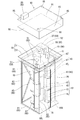
- one unit of the wave power generator includes a fixed floor member 30, four water turbines 40, a power generator 50, a frame 60, a front plate 70, left and right rectifying plates 80L and 80R. , And a cover 90.
- the fixed floor member 30 has a quadrangular floor 31 that is large enough to cover one upper opening 19 ⁇ / b> A, and a standing wall 33 that rises upward from the periphery of the floor 31.
- the standing wall portion 33 has a belt shape and a predetermined height.
- the floor portion 31 and the standing wall portion 33 are formed of a resin-made sheet member having waterproofness.
- the water wheel 40 provided in each unit has a shaft portion 41 and a rotary blade portion 43 formed around the shaft portion 41.
- the shaft portion 41 penetrates the floor portion 31 of the fixed floor member 30 in the vertical direction so as to be watertight and rotatable.
- the fixed floor member 30 is formed of a waterproof sheet member, and the shaft portion 41 penetrates in a watertight manner and is rotatably mounted. Therefore, the fixed floor member 30 is placed on the wave-dissipating block 10 and fixed. Then, water can be prevented from flowing out from the first wave-dissipating space R1 above the fixed floor member 30.
- the rotary wing portion 43 includes four fixing members 45 and three sets of six wing members 47.
- Each fixing member 45 has a disk shape with a shaft 41 passing through the center.
- the four fixing members 45 are fixed at equal intervals in the vertical direction of the shaft portion 41 positioned below the fixed floor member 30.
- the lowermost fixing member 45 is fixed to the lower end portion of the shaft portion 41.
- Each wing member 47 is formed of a semi-cylindrical member as shown in FIGS.
- the rotary blade portion 43 is formed by fixing a pair of blade members 47 with the shaft portion 41 symmetrical between the fixed members 45 fixed to the shaft portion 41.
- This water wheel 40 is a saponius type water wheel.
- the four water turbines 40 provided in one unit of the wave power generation apparatus are used for the first wave-dissipation from the left and right end edges of the opening 71 of the front plate 70 described later.
- the left and right rectifying plates 80L and 80R extending into the space R1 they are arranged in parallel in the left-right direction.
- the shaft portion 41 of the water wheel 40 arranged in parallel in the left-right direction is separated from the opening portion 71 while being separated from each other.
- this wave power generator can enlarge the diameter of the water wheel 40 compared with the case where the distance of the axial part 41 of the adjacent water wheel 40 is near.
- the remaining two water turbines 40 are located farther from the opening 71 than the two water turbines 40 arranged in the vicinity of the left and right rectifying plates 80L and 80R, and are arranged in the vicinity of the left and right rectifying plates 80L and 80R.
- the two water turbines 40 are arranged in parallel in the left-right direction at an interval narrower than the left-right interval.
- the power generator 50 provided in each unit includes four fluid pressure pumps 51, a circulation channel 53, one fluid pressure motor 55, one generator 57, and One power conditioner (power conditioner) 59 is provided.
- Each fluid pressure pump 51 connects the upper end portion of the shaft portion 41 of each water wheel 40 and is mounted on the fixed floor member 30.
- Each fluid pressure pump 51 has a working fluid outflow port 51A and an inflow port 51B.
- Each fluid pressure pump 51 supplies and discharges the working fluid in one direction.
- the fluid pressure motor 55 and the generator 57 are accommodated in a single case 52 and attached to the fixed floor member 30.
- the fluid pressure motor 55 supplies and discharges the working fluid in one direction, and the rotating shaft rotates in one direction.
- the fluid pressure motor 55 has a hydraulic oil inflow port 55A and an outflow port 55B.
- the circulation flow path 53 has four fluid pressure pumps 51 connected in parallel to the fluid pressure motor 55. Specifically, as shown in FIG. 4, the circulation flow path 53 includes a plurality of first flow paths 53 ⁇ / b> A connected to the outflow ports 51 ⁇ / b> A of the fluid pressure pumps 51, and a fluid pressure motor by joining the first flow paths 53 ⁇ / b> A.
- the upstream side flow path 53B connected to the inflow port 55A of 55, the downstream side flow path 53C connected to the outflow port 55B of the fluid pressure motor 55, and the inflow port of each fluid pressure pump 51 by branching the downstream side flow path 53C And a plurality of second flow paths 53D communicating with 51B.
- a first check valve 54 is provided in the first flow path 53A, and a second check valve 56 is provided in the second flow path 53D so that the working fluid flows in one direction.
- the power conditioner 59 is attached to a cover 90 described later.
- the power conditioner 59 is connected to the generator 57 and converts the electricity generated by the DC generator so that it can be used at home.
- the frame 60 includes upper and lower frames 61 and 61, four vertical frames 63, an X-shaped connecting frame 65, and two upper and lower connecting frames 67.
- the upper and lower frame 61 is formed in a quadrangular shape whose four sides are smaller than the outer shape of the floor portion 31 of the fixed floor member 30.
- the four vertical frames 63 connect the corners of the upper and lower frames 61 to each other.
- the connection frame 65 obliquely connects the upper end portions and the lower end portions of the two vertical frames 63 positioned on the rear side, which is a pair of vertical frames 63.
- the pair of vertical frames 63 are located away from the fixed floor member 30 at a position farther from the front wall 11 of the wave-dissipating block 10 than the water wheel 40 in a state where the fixed floor member 30 is placed on the wave-dissipating block 10. It is drooping.
- the two upper and lower connecting frames 67 connect the left and right intermediate portions of the upper and lower frames 61.
- the upper frame 61 is the lower surface of the floor portion 31 of the fixed floor member 30, and is connected to the inner side of the outer peripheral edge of the floor portion 31.
- the vertical frame 63 is longer in the vertical dimension than the vertical dimension of the water wheel 40 depending from the fixed floor member 30.
- the lower frame 61 is disposed below the water wheel 40 and is connected to the lower ends of the pair of vertical frames 63. As described above, the frame 60 is positioned around the four water wheels 40 depending from the fixed floor member 30. For this reason, when the wave power generator is attached to and detached from the wave-dissipating block 10, that is, when the four water turbines 40 are taken in and out of the first wave-dissipating space R ⁇ b> 1. Collision with the upper wall portion 19 and the like of the block 10 is prevented.
- the front plate 70 is a flat plate and is attached to the front surfaces of the upper and lower frames 61 and 61 of the frame 60 and the two vertical frames 63 and 63 positioned on the front side. That is, the front plate 70 is attached in a state of hanging from the fixed floor member 30.
- the front plate 70 is formed with a slit-like opening 71 extending in the vertical direction at the left and right central portions.
- the opening 71 is provided for one first wave-dissipating space R1 when the wave power generation device is attached to the wave-dissipating block 10 and the front plate 70 is inserted into the first wave-dissipating space R1.
- the three first front openings 11A are overlaid on the first front opening 11A located at the center (see FIG. 3).
- the left and right rectifying plates 80L and 80R have the same vertical dimension as the vertical dimension of the front plate 70, and are formed by bending a rectangular plate material that is long in the vertical direction.
- the left rectifying plate 80L disposed on the left side of the opening 71 of the front plate 70 has one long side portion connected to the left edge extending in the vertical direction of the opening 71 of the front plate 70. Further, the left rectifying plate 80L extends in the left direction while curving in the frame 60, and the other long side portion is coupled to the left upper and lower coupling frame 67.
- the right rectifying plate 80 ⁇ / b> R disposed on the right side of the opening 71 of the front plate 70 has one long side connected to the right edge extending in the vertical direction of the opening 71 of the front plate 70.
- the right rectifying plate 80R extends in the right direction while curving in the frame 60, and the other long side portion is connected to the right vertical coupling frame 67.
- the left and right rectifying plates 80L and 80R are provided on the left and right sides of the first front opening 11A formed on the front wall 11 of the wave-dissipating block 10 in a state where the fixed floor member 30 is placed on the wave-dissipating block 10. The both ends extend into the first wave-dissipating space R1.
- the left and right rectifying plates 80L and 80R have larger dimensions as they move away from the first front opening 11A formed in the front wall 11 of the wave-dissipating block 10.
- the waves can flow in and out of the opening 71 of the front plate 70 and the first front opening 11A of the wave-dissipating block 10 in the first wave-dissipating space R1.
- a front plate 70 and left and right rectifying plates 80L and 80R are attached to a frame 60. That is, the wave power generator is reinforced by attaching the front plate 70 and the left and right rectifying plates 80L and 80R to the frame 60. For this reason, this wave power generator can further improve the wave resistance performance.
- the cover 90 is similar to the floor portion 31 of the fixed floor member 30 and has a slightly larger rectangular upper surface portion 91 and a peripheral wall portion that hangs downward from the periphery of the upper surface portion 91. 93 and four hooks 95 attached to the four corners of the upper surface portion 91.
- the peripheral wall portion 93 has a strip shape and the vertical dimension is larger than the vertical dimension of the standing wall portion 33 of the fixed floor member 30.
- the cover 90 is pulled up by connecting a lifting device such as a crane car to the hook 95, and is attached to the fixed floor member 30 and the floor portion 31 of the fixed floor member 30 from the upper side of the fixed floor member 30. It is placed so as to cover each component.
- a power conditioner 59 is attached to the cover 90 on the upper surface portion 91.
- the wave power generation device mounts the cover 90 from the upper side of the fixed floor member 30 so that each component of the power generation device 50 attached to the floor portion 31 of the fixed floor member 30 (the fluid pressure pump 51, the circulation flow path). 53, fluid pressure motor 55, generator 57, etc.) can be prevented from being rained or splashed.
- the wave power generator is attached to the wave-dissipating block 10 installed on the quay facing the sea, the floor portion of the fixed floor member 30 is mounted by placing the cover 90 from the upper side of the fixed floor member 30.
- This wave power generation device can be easily attached and detached by connecting a lifting tool such as a crane truck to four hooks 95 attached to the four corners of the upper surface portion 91 of the cover 90. Thereby, this wave power generator can easily perform maintenance.
- This wave power generator unit izes the fixed floor member 30, four water turbines 40, the power generator unit 50, the frame 60, the front plate 70, and the left and right rectifying plates 80L and 80R (unitized). For this reason, this wave power generation device is formed on the upper wall portion 19 for each first wave-dissipating space R1 of the wave-dissipating block 10 and is arranged below the fixed floor member 30 from the upper opening 19A.
- the fixed floor member 30 can be placed and fixed on the wave-dissipating block 10 while inserting the water wheel 40 and the frame 60 into the first wave-dissipating space R1.
- the cover 90 is placed from the upper side of the fixed floor member 30 after fixing the fixed floor member 30 to the wave-dissipating block 10.
- the wave power generator can be attached to the wave-dissipating block 10. That is, this wave power generation device can be installed later (add-on) in the upper opening 19A of the wave-dissipating block 10 installed on the quay. For this reason, when installing this wave power generation device, it is not necessary for an operator to submerge, and it is possible to reduce the installation effort. Further, when performing maintenance or the like of the water wheel 40, the water wheel 40 can be pulled out from the first wave-dissipating space R1 while removing the cover 90 and then removing the fixed floor member 30 from the wave-dissipating block 10. Thereby, this wave power generation device can easily perform maintenance without the operator diving.
- the wave power generation apparatus is fixed by placing the fixed floor member 30 on the wave-dissipating block 10.
- the wave-dissipating block 10 has a front wall portion 11 and an upper wall portion 19.
- the front wall 11 of the wave-dissipating block 10 is formed with 15 slit-shaped first front openings 11A extending in the vertical direction with the wave-dissipating block 10 installed on the quay.
- the first front opening 11A communicates the first wave-dissipating space R1 formed inside the wave-dissipating block 10 with the outside.
- the upper wall portion 19 of the wave-dissipating block 10 is formed with an upper opening portion 19A that opens above the wave-dissipating space.
- the wave power generation device includes a fixed floor member 30, a water wheel 40, and a power generation device 50.
- the water wheel 40 is rotatably attached to the fixed floor member 30.
- the water wheel 40 is inserted into the first wave-dissipating space R1 from the upper opening 19A of the wave-dissipating block 10.
- the power generation device 50 is attached on the fixed floor member 30.
- the power generation device 50 generates power when the water wheel 40 rotates.
- a turbine 40 and a power generation device 50 are attached to a fixed floor member 30.
- the wave power generator is configured such that the water wheel 40 is moved from the upper opening portion 19 ⁇ / b> A of the upper wall portion 19 of the wave-dissipating block 10 to the first position. It can be inserted and arranged in the first wave-dissipating space R1, and the power generation device 50 can be assembled to the wave-dissipating block 10.
- this wave power generation device if the fixed floor member 30 is removed from the wave-dissipating block 10, the water wheel 40 can be pulled out from the first wave-dissipating space R1, and the power generation device 50 is removed from the wave-dissipating block 10. Can be removed.
- the wave power generator of Embodiment 1 can be easily attached to and detached from the wave-dissipating block 10.
- this wave power generation device includes a front plate 70 that hangs down from the fixed floor member 30.
- the front plate 70 has a slit-like opening 71 that is superimposed on the first front opening 11A of the wave-dissipating block.
- this wave power generation device forms the opening 71 in the front plate 70 suspended from the fixed floor member 30 to which the water wheel 40 is attached, the water wheel 40 and the opening through which waves flow in and out.
- the positional relationship with 71 can be accurately set to a predetermined position in advance.
- this wave power generator can arrange
- the fixed floor member 30 of this wave power generation device has waterproofness, and the shaft portion 41 penetrates in a watertight manner and is rotatably attached, so that it is located above the fixed floor member 30 from the wave-dissipating space. Prevent outflow of water.
- water in the first wave-dissipating space R1 does not flow out onto the fixed floor member 30, and the power generation device 50 attached on the fixed floor member 30 is immersed in water. Can be prevented.
- the power generating device 50 can suppress the working fluid from leaking out from the fixed floor member 30. For this reason, this wave power generator can generate electric power satisfactorily for a long time.
- the wave power generation apparatus includes a pair of vertical frames 63, a connecting frame 65, and a lower frame 61.
- the pair of vertical frames 63 hang down from the fixed floor member 30 at a position farther from the front wall 11 of the wave-dissipating block 10 than the water wheel 40 in a state where the fixed floor member 30 is placed on the wave-dissipating block 10.
- the connecting frame 65 obliquely connects the upper end portion and the lower end portion of the pair of vertical frames 63.
- the lower frame 61 is disposed below the water wheel 40 and is connected to the lower ends of the pair of vertical frames 63.
- the wave power generation device can prevent the water wheel 40 from colliding with the upper wall portion 19 or the like of the wave-dissipating block 10 when the water wheel 40 is taken in and out of the first wave-dissipating space R1.
- this wave power generation device includes a pair of rectifying plates 80R and 80L.
- the pair of rectifying plates 80R and 80L are arranged from the left and right edges of the front opening 11A formed in the front wall 11 of the wave-dissipating block 10 in a state where the fixed floor member 30 is placed on the wave-dissipating block 10.
- the dimension between the first extinguishing space R1 and the distance between the front opening 11A increases as the distance from the front opening 11A increases.
- this wave power generation device can flow in and out of the opening 71 of the front plate 70 and the front opening 11A of the wave-dissipating block 10 without wave stagnation in the first wave-dissipating space R1.
- the wave power generation device includes the front plate, but the front plate may not be provided.
- one opening is formed in the front plate of the wave power generation device, but a plurality of openings are formed so as to overlap with the first front opening provided in the wave-dissipating block. The part may be formed on the front plate.
- the wave power generation device includes the rectifying plate, but may not include the rectifying plate.
- one wave power generation device includes four water turbines, but may include one to three or five or more water turbines.
- the water turbine of the wave power generation device is a Saponius type water turbine, but may be a water turbine of another form.
- the power generation device uses the fluid pressure pump, the circulation flow path, and the fluid pressure motor to convert the rotational energy of the water turbine into the drive energy of the power generator to generate power.
- a generator may be directly connected to the shaft portion to generate power.
- the fixed floor member is formed from a resin sheet member, but a waterproof sheet different from the fixed floor member is overlaid on the fixed floor member and fixed from the first wave-dissipating space. Water may be prevented from flowing out above the floor member.
- the wave power generation device includes the cover, but the cover may not be provided.
- Embodiment 1 concrete is filled inside the quayside space, but this is not a limitation, and crushed stone or the like may be filled inside the quayside space.
- three first front openings are provided for each first wave-dissipating space, but this is not limiting, and the first front opening is provided for each first wave-dissipating space. Less than three may be penetrated, and more than three may be penetrated. In this case, the front wall portion does not cover the opening of the front plate in a state where the wave power generation device is fixed in the first wave-dissipating space.
- SYMBOLS 10 Block for wave-dissipation, 11 ... Front wall part, 11A ... 1st front opening part (front opening part), 19 ... Upper wall part, 19A ... Upper opening part, R1 ... Space for 1st wave-dissipation (for wave-dissipation) Space), 30 ... fixed floor member, 40 ... water wheel, 41 ... shaft, 50 ... power generation device, 61 ... lower frame, 63 ... vertical frame, 65 ... connecting frame, 70 ... front plate, 71 ... opening, 80R, 80L ... Left and right rectifying plate (a pair of rectifying plates)
Landscapes
- Engineering & Computer Science (AREA)
- Chemical & Material Sciences (AREA)
- Combustion & Propulsion (AREA)
- Mechanical Engineering (AREA)
- General Engineering & Computer Science (AREA)
- Other Liquid Machine Or Engine Such As Wave Power Use (AREA)
Abstract
消波用ブロックへの着脱を容易に行うことができる波力発電装置を提供する。 波力発電装置は固定床部材(30)を消波用ブロック(10)に載置して固定される。消波用ブロック(10)の前壁部(11)は、消波用ブロック(10)の内部に形成された第1消波用空間(R1)と外部とを連通し、鉛直方向に伸びた複数のスリット状の第1前開口部(11A)が形成されている。消波用ブロック(10)の上壁部(19)は第1消波用空間(R1)の上方を開口した上開口部(19A)が形成されている。波力発電装置の水車(40)は軸部(41)が固定床部材(30)に貫通して回転自在に取り付けられており、消波用ブロック(10)の上開口部(19A)から第1消波用空間(R1)内に挿入される。波力発電装置の発電装置(50)は固定床部材(30)上に取り付けられており、水車(40)が回転することによって発電する。
Description
本発明は波力発電装置に関するものである。
特許文献1の図1及び図2は従来の波力発電装置を開示している。波力発電装置は消波用ブロック(block)に取り付けられている。消波用ブロックは前壁部と上壁部とを具備している。消波用ブロックの前壁部は、岸壁に消波用ブロックを設置した際、鉛直方向に伸びたスリット(slit)状の前開口部を有している。前開口部は消波用ブロックの内部に形成された消波用空間と外部とを連通している。波力発電装置は、複数の水車、及び発電装置を備えている。水車は、軸部と、軸部の周りに形成された回転翼部とを有している。軸部は、消波用ブロックの上壁部を貫通して鉛直方向に伸びている。回転翼部は前開口部に沿って消波用空間内に垂下している。発電装置は、複数の油圧ポンプ(pump)、作動油の循環路、一つの油圧モーター(motor)、及び一つの発電機を有している。油圧ポンプは、水車の軸部の上端が連結した状態で、消波用ブロックの上壁部に載置され固定されている。循環路は複数の油圧ポンプと一つの油圧モーターとを連通している。油圧モーターは複数の油圧ポンプが給排する作動油によって回転する。発電機は、油圧モーターに連結されており、油圧モーターの駆動によって発電する。この波力発電装置は、複数の水車が回転することによって、一つの油圧モーターが駆動され、発電機が発電する。このため、この波力発電装置は各水車の回転がばらついても安定的に発電することができる。
しかし、特許文献の波力発電装置は、消波用ブロックに水車や油圧ポンプ等を個別に取り付ける必要がある。このため、この波力発電装置は消波用ブロックへの取り付けに手間を要する。また、この波力発電装置は、メンテナンス(maintenance)をする際も、消波用ブロックに対する水車や油圧ポンプ等の取り外し及び取り付けに手間を要する。
本発明は、上記従来の実情に鑑みてなされたものであって、消波用ブロックへの着脱を容易に行うことができる波力発電装置を提供することを解決すべき課題としている。
本発明の波力発電装置は固定床部材を消波用ブロックに載置して固定される。消波用ブロックは前壁部と上壁部とを有している。消波用ブロックの前壁部は、消波用ブロックが岸壁に設置された状態で鉛直方向に伸びた複数のスリット状の前開口部が形成されている。前開口部は消波用ブロックの内部に形成された消波用空間と外部とを連通している。消波用ブロックの上壁部は消波用空間の上方を開口した上開口部が形成されている。波力発電装置は、固定床部材、水車、及び発電装置を備えている。水車は軸部が固定床部材に貫通して回転自在に取り付けられている。この水車は消波用ブロックの上開口部から消波用空間内に挿入される。発電装置は固定床部材上に取り付けられている。この発電装置は水車が回転することによって発電する。
本発明の波力発電装置は固定床部材から垂下した前板を備えている。この前板は消波ブロックの前開口部に重ね合わせられるスリット状の開口部を有している。
本発明の波力発電装置の固定床部材は防水性を有し、軸部が水密状に貫通して回転自在に取り付けられており、消波用空間から固定床部材よりも上方に水が流出することを防止する。
本発明の波力発電装置は、一対の縦枠、連結枠、及び下枠を備えている。一対の縦枠は固定床部材が消波用ブロックに載置された状態で、消波用ブロックの前壁部から水車よりも離れた位置で固定床部材から垂下する。連結枠は一対の縦枠の上端部と下端部とを斜めに連結する。下枠は水車の下方に配置され、一対の縦枠の下端に連結する。
本発明の波力発電装置は一対の整流板を備えている。一対の整流板は固定床部材が消波用ブロックに載置された状態で、消波用ブロックの前壁部に形成された前開口部の左右両端縁から消波用空間内に伸びて、前開口部から離れるにつれて互いの間の寸法が大きくなる。
本発明の波力発電装置を具体化した実施形態1について、図面を参照しつつ説明する。
<実施形態1>
実施形態1の波力発電装置は、図1に示すように、消波用ブロック10に載置して固定される。複数個の消波用ブロック10が岸壁に沿って設置される。消波用ブロック10は後述する後壁部15が岸壁側に位置して設置される。消波用ブロック10は、コンクリート(concrete)で形成されており、外形が略直方体形状である。この消波用ブロック10は、前壁部11、左右側壁部13,13、後壁部15、及び底壁部17を有している。
実施形態1の波力発電装置は、図1に示すように、消波用ブロック10に載置して固定される。複数個の消波用ブロック10が岸壁に沿って設置される。消波用ブロック10は後述する後壁部15が岸壁側に位置して設置される。消波用ブロック10は、コンクリート(concrete)で形成されており、外形が略直方体形状である。この消波用ブロック10は、前壁部11、左右側壁部13,13、後壁部15、及び底壁部17を有している。
前壁部11は、平板状であり、左右方向に長い長方形状である。ここで、左右方向とは消波用ブロック10が岸壁に設置された状態で岸壁が水平方向で伸びている方向(図1の両矢印X方向)である(以下、同じ。)。左右側壁部13,13は、平板状であり、同形状である。この左右側壁部13,13は上下寸法が前壁部11の上下寸法と同じであり、上下方向に長い長方形状である。ここで、上下方向とは消波用ブロック10が岸壁に設置された状態の鉛直方向(図1の両矢印Z方向)である(以下、同じ。)。左右側壁部13,13は前壁部11の左右両端部に連続している。この左右側壁部13,13は前壁部11に対して直角に後方向に伸びている。ここで、後方向とは消波用ブロック10が岸壁に設置された状態で前壁部11から岸壁に向いた方向(図1の矢印Y方向)である。後壁部15は平板状である。後壁部15は、外形状が前壁部11の外形状と同じであり、左右方向に長い長方形状である。後壁部15は、左右側壁部13,13の後端部に左右両端部が連続し、前壁部11に平行である。底壁部17は平板状である。底壁部17は、左右寸法が前壁部11及び後壁部15の左右寸法と同じであり、左右方向に長い長方形状である。底壁部17は、前壁部11、左右側壁部13,13、及び後壁部15で囲まれた下端開口を封鎖し、後端部が後壁部15より後方向にはみ出している。
また、消波用ブロック10は、前壁部11、左右側壁部13,13、後壁部15、及び底壁部17に囲まれた内部空間を仕切る第1隔壁部21、第2隔壁部22、第3隔壁部23、第4隔壁部24、及び第5隔壁部25を有している。第1隔壁部21は平板状である。この第1隔壁部21は、左右方向に長い長方形状であり、左右側壁部13,13の前後中央部に左右両端部が連続し、前壁部11と後壁部15とに平行に伸びている。つまり、第1隔壁部21は内部空間を前側の前方空間と後側の後方空間に区画している。第2隔壁部22は、平板状であり、横方向に長い長方形状である。第2隔壁部22は前方空間を上下に略2等分している。つまり、第2隔壁部22は、4つの外周辺部の夫々が、前壁部11、左右側壁部13,13の前側、及び第1隔壁部21の夫々の上下方向の略中央部に連続している。
第3隔壁部23は、平板状であり、上下方向に長い長方形状である。第3隔壁部23は、4枚設けられており、第2隔壁部22によって区画された前方空間の上側空間を左右方向に略5等分している。つまり、4枚の第3隔壁部23は、消波用ブロック10の前方空間の上側空間の左右方向に略等間隔に設けられている。各第3隔壁部23は、外周辺部の3辺が前壁部11の上側、第1隔壁部21の上側、及び第2隔壁部22に連続している。このように、消波用ブロック10の前方空間の上側空間を分割して形成された5室の夫々が第1消波用空間R1である。消波用ブロック10は、各第1消波用空間R1の上方が開口しており、5個の上開口部19Aを形成した上壁部19を有している。上壁部19は、前壁部11、左右側壁部13,13、第1隔壁部21、及び第3隔壁部23の上端部によって形成されている。
第4隔壁部24は、平板状であり、上下方向に長い長方形状である。第4隔壁部24は、4枚設けられており、第2隔壁部22によって区画された前方空間の下側空間を左右方向に略5等分している。つまり、4枚の第4隔壁部24は、消波用ブロック10の前方空間の下側空間の左右方向に略等間隔に設けられている。各第4隔壁部24は、外周辺部の夫々が前壁部11の下側、第1隔壁部21の下側、第2隔壁部22、及び底壁部17の前側に連続している。このように、消波用ブロック10の前方空間の下側空間を分割して形成された5室が第2消波用空間R2である。
第5隔壁部25は平板状である。この第5隔壁部25は、上下寸法が第1隔壁部21の上下寸法と同じであり、上下方向に長い長方形状である。第5隔壁部25は、4枚設けられており、第2隔壁部22によって区画された後方空間を左右方向に略5等分している。つまり、4枚の第5隔壁部25は、消波用ブロック10の後方空間の左右方向に略等間隔に設けられている。各第5隔壁部25は、外周辺部の3辺が第1隔壁部21、底壁部17の後側、後壁部15に連続している。
この消波用ブロック10は、5室の第1消波用空間R1、5室の第2消波用空間R2及び5室の岸壁側空間R3を有している。前壁部11は、消波用ブロック10が岸壁に設置された状態で鉛直方向に伸びたスリット状の第1前開口部11Aを第1消波用空間R1毎に3個ずつ貫設している。つまり、前壁部11は15個の第1前開口部11Aを貫設している。各第1前開口部11Aは第1消波用空間R1と外部とを連通している。また、前壁部11は、正方形状の第2前開口部11Bを第2消波用空間R2毎に1個ずつ貫設している。つまり、前壁部11は第2前開口部11Bを第1前開口部11Aより下側に設けている。各第2前開口部11Bは第2消波用空間R2と外部とを連通している。5室の岸壁側空間R3はそれぞれの内側にコンクリートが充填されている。これにより、この消波用ブロック10は、海に面した岸壁に設置された場合に、強い波がぶつかっても倒れたり、流失したりすることを抑えることができる。
波力発電装置は各第1消波用空間R1に1ユニット(unit)ずつ取り付けられる。波力発電装置の1ユニットは、図2及び図3に示すように、固定床部材30、4個の水車40、発電装置50、フレーム(flame)60、前板70、左右整流板80L,80R、及びカバー(cover)90を備えている。固定床部材30は、1つの上開口部19Aを塞ぐ大きさの四角形状の床部31と、床部31の周縁から上方に立ち上がった立壁部33とを有している。立壁部33は帯状であり所定の高さを有している。床部31と立壁部33とは防水性を有する樹脂製のシート(sheet)部材から形成されている。
各ユニットに設けられた水車40は、軸部41と、軸部41の周りに形成された回転翼部43とを有している。軸部41は固定床部材30の床部31を水密状かつ回転自在に上下方向に貫通している。このように、固定床部材30は、防水性を有するシート部材から形成され、軸部41が水密状に貫通して回転自在に取り付けられているため、消波用ブロック10に載置して固定されると、第1消波用空間R1から固定床部材30よりも上方に水が流出することを防止することができる。回転翼部43は、図2に示すように、4個の固定部材45と、3組6個の翼部材47とを有している。各固定部材45は中心に軸部41が貫通した円盤状である。4個の固定部材45は固定床部材30よりも下方に位置する軸部41の上下方向に等間隔で固定されている。最も下の固定部材45は軸部41の下端部に固定されている。各翼部材47は、図2及び図3に示すように、半円筒部材で構成されている。回転翼部43は軸部41に固定された固定部材45の間の夫々に軸部41を対称にして一対の翼部材47が固定されて形成されている。この水車40はサポニウス(savonius)型水車である。
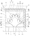
波力発電装置の1ユニットに設けられた4個の水車40は、図3に示すように、2個の水車40を後述する前板70の開口部71の左右両端縁から第1消波用空間R1内に伸びる左右整流板80L,80Rの近傍に左右方向に並列させて配置している。この波力発電装置は、左右方向に並列した水車40の軸部41を開口部71から離しつつ、互いの距離を離している。これにより、この波力発電装置は隣り合う水車40の軸部41の距離が近い場合と比べて、水車40の直径を大きくすることができる。これにより、この波力発電装置は水車40に勢いの弱い波がぶつかっても水車40が効率よく回転することができる。残りの2個の水車40は、左右整流板80L,80Rの近傍に配置された2個の水車40よりも開口部71から離れた位置であり、左右整流板80L,80Rの近傍に配置された2個の水車40の左右間隔よりも狭い間隔で左右方向に並列させて配置している。このように4個の水車40を配置することによって、前板70の開口部71を流入出する波が各水車40を効率よく回転させることができる。
各ユニットに設けられた発電装置50は、図2及び図4に示すように、4個の流体圧ポンプ51、循環流路53、1個の流体圧モーター55、1個の発電機57、及び1個のパワーコンディショナー(power conditioner)59を有している。各流体圧ポンプ51は、各水車40の軸部41の上端部を連結し、固定床部材30上に取り付けられている。各流体圧ポンプ51は作動流体の流出ポート(port)51Aと流入ポート51Bとを有している。各流体圧ポンプ51は一方向に作動流体を給排する。流体圧モーター55及び発電機57は、1個のケース(case)52内に収納され、固定床部材30上に取り付けられている。流体圧モーター55は、一方向に作動流体が給排され、一方向に回転軸が回転する。流体圧モーター55は作動油の流入ポート55Aと流出ポート55Bとを有している。循環流路53は流体圧モーター55に対して4つの流体圧ポンプ51を並列に接続している。詳しくは、図4に示すように、循環流路53は、各流体圧ポンプ51の流出ポート51Aに接続した複数の第1流路53Aと、これら第1流路53Aを合流させて流体圧モーター55の流入ポート55Aに接続した上流側流路53Bと、流体圧モーター55の流出ポート55Bに接続した下流側流路53Cと、下流側流路53Cを分岐して各流体圧ポンプ51の流入ポート51Bに連通する複数の第2流路53Dとを有している。また、循環流路53は一方向に作動流体が流れるように、第1流路53Aに第1逆止弁54が設けられ、第2流路53Dに第2逆止弁56が設けられている。パワーコンディショナー59は、図2に示すように、後述するカバー90に取り付けられている。パワーコンディショナー59は、発電機57に接続されており、直流発電機が発電した電気を家庭で利用することができるように変換する。
フレーム60は、図2及び図3に示すように、上下枠61、61、4本の縦枠63、X状の連結枠65、及び2本の上下連結枠67を有している。上下枠61は4辺が固定床部材30の床部31の外形よりも小さい四角形状に形成されている。4本の縦枠63は上下枠61の角部同士を連結している。連結枠65は一対の縦枠63である後側に位置する2本の縦枠63の上端部と下端部とを斜めに連結している。この一対の縦枠63は、固定床部材30が消波用ブロック10に載置された状態で、消波用ブロック10の前壁部11から水車40よりも離れた位置で固定床部材30から垂下している。2本の上下連結枠67は上下枠61の左右の中間部を連結している。フレーム60は、上枠61が固定床部材30の床部31の下面であって、床部31の外周縁よりも内側に連結されている。縦枠63は上下寸法が固定床部材30から垂下する水車40の上下寸法よりも長い。つまり、下枠61は水車40の下方に配置され、一対の縦枠63の下端に連結している。このように、フレーム60は固定床部材30から垂下している4個の水車40の周りに位置している。このため、フレーム60は、波力発電装置を消波用ブロック10に着脱する際、つまり、4個の水車40を第1消波用空間R1に出し入れする際、4個の水車40が消波用ブロック10の上壁部19等に衝突することを防止している。
前板70は、平板であり、フレーム60の上下枠61、61及び前側に位置する2本の縦枠63、63の前面に取り付けられている。つまり、前板70は固定床部材30から垂下した状態に取り付けられている。この前板70は左右中央部に鉛直方向に伸びたスリット状の開口部71を形成している。開口部71は、波力発電装置を消波用ブロック10に取り付け、第1消波用空間R1に前板70を挿入した際、1個の第1消波用空間R1に対して設けられた3個の第1前開口部11Aの内で中央に位置する第1前開口部11Aに重ね合わせられる(図3参照)。
左右整流板80L,80Rは、上下寸法が前板70の上下寸法と同じであり、上下方向に長い長方形状の板材を湾曲させて形成されている。前板70の開口部71の左側に配置された左整流板80Lは一方の長辺部を前板70の開口部71の上下方向に伸びる左側端縁に連結させている。また、この左整流板80Lは、フレーム60内を湾曲しながら左方向に伸びており、他方の長辺部を左側の上下連結枠67に連結している。また、前板70の開口部71の右側に配置された右整流板80Rは一方の長辺部を前板70の開口部71の上下方向に伸びる右側端縁に連結されている。また、この右整流板80Rは、フレーム60内を湾曲しながら右方向に伸びており、他方の長辺部を右側の上下連結枠67に連結している。つまり、左右整流板80L,80Rは、固定床部材30が消波用ブロック10に載置された状態で、消波用ブロック10の前壁部11に形成された第1前開口部11Aの左右両端縁から第1消波用空間R1内に伸びている。さらに、左右整流板80L,80Rは、消波用ブロック10の前壁部11に形成された第1前開口部11Aから離れるにつれて互いの間の寸法が大きくなっている。左右整流板80L,80Rによって、第1消波用空間R1内で波が淀みなく前板70の開口部71及び消波用ブロック10の第1前開口部11Aを流入出することができる。この波力発電装置はフレーム60に、前板70及び左右整流板80L,80Rが取り付けられている。つまり、この波力発電装置はフレーム60に前板70及び左右整流板80L,80Rを取り付けることによって補強されている。このため、この波力発電装置は、耐波性能をより向上させることができる。
カバー90は、図1及び図2に示すように、固定床部材30の床部31に相似形であり僅かに大きい四角形状の上面部91と、上面部91の周縁から下方に垂下した周壁部93と、上面部91の4隅に取り付けられた4個のフック(hook)95とを有している。周壁部93は帯状であり上下寸法が固定床部材30の立壁部33の上下寸法よりも大きい。カバー90は、フック95にクレーン(crane)車等の吊上げ具を連結して引上げ、固定床部材30の上側から固定床部材30及び固定床部材30の床部31に取り付けられた発電装置50の各構成物を覆うように載置される。カバー90は上面部91上にパワーコンディショナー59が取り付けられている。波力発電装置は、カバー90を固定床部材30の上側から載置することによって、固定床部材30の床部31に取り付けられた発電装置50の各構成物(流体圧ポンプ51、循環流路53、流体圧モーター55、発電機57等)に雨や波しぶき等がかかることを防止することができる。また、波力発電装置が海に面した岸壁に設置された消波用ブロック10に取り付けられた場合、カバー90を固定床部材30の上側から載置することによって、固定床部材30の床部31に取り付けられた発電装置50の各構成物の塩害を防止することができる。また、この波力発電装置は、カバー90の上面部91の4隅に取り付けられた4個のフック95にクレーン車等の吊上げ具を連結することによって容易にカバー90の着脱ができる。これにより、この波力発電装置はメンテナンスを容易に実施することができる。
この波力発電装置は、固定床部材30、4個の水車40、発電装置50、フレーム60、前板70、及び左右整流板80L,80Rを一体にしている(ユニット化されている。)。このため、この波力発電装置は、消波用ブロック10の第1消波用空間R1毎に上壁部19に形成され上開口部19Aから固定床部材30より下方に配置された4個の水車40及びフレーム60を第1消波用空間R1に挿入しながら、固定床部材30を消波用ブロック10に載置して固定することができる。カバー90は、消波用ブロック10に固定床部材30を固定した後、固定床部材30の上側から載置される。このようにして、この波力発電装置は消波用ブロック10に取り付けることができる。つまり、この波力発電装置は岸壁に設置された消波用ブロック10の上開口部19Aに後から設置(アドオン(add on))することができる。このため、この波力発電装置は、設置する際に作業者が潜水する必要がなく、設置する手間を抑えることができる。また、水車40のメンテナンス等を行う際は、カバー90を取り外した後、固定床部材30を消波用ブロック10から取り外しながら、水車40を第1消波用空間R1から引き抜くことができる。これにより、この波力発電装置は作業者が潜水することなくメンテナンスを容易に実施することができる。
このように、この波力発電装置は固定床部材30を消波用ブロック10に載置して固定される。消波用ブロック10は前壁部11と上壁部19とを有している。消波用ブロック10の前壁部11は、消波用ブロック10が岸壁に設置された状態で鉛直方向に伸びた15個のスリット状の第1前開口部11Aが形成されている。第1前開口部11Aは消波用ブロック10の内部に形成された第1消波用空間R1と外部とを連通している。消波用ブロック10の上壁部19は消波用空間の上方を開口した上開口部19Aが形成されている。波力発電装置は、固定床部材30、水車40、及び発電装置50を備えている。水車40は固定床部材30に回転自在に取り付けられている。この水車40は消波用ブロック10の上開口部19Aから第1消波用空間R1内に挿入される。発電装置50は固定床部材30上に取り付けられている。この発電装置50は水車40が回転することによって発電する。
この波力発電装置は固定床部材30に水車40及び発電装置50が取り付けられている。このため、この波力発電装置は、固定床部材30を消波用ブロック10に載置して固定する際に、水車40を消波用ブロック10の上壁部19の上開口部19Aから第1消波用空間R1内に挿入して配置することができ、かつ、発電装置50を消波用ブロック10に組み付けることができる。また、この波力発電装置は、固定床部材30を消波用ブロック10から取り外せば、水車40を第1消波用空間R1から引き抜くことができ、かつ発電装置50を消波用ブロック10から取り外すことができる。
したがって、実施形態1の波力発電装置は消波用ブロック10への着脱を容易に行うことができる。
また、この波力発電装置は固定床部材30から垂下した前板70を備えている。この前板70は消波ブロックの第1前開口部11Aに重ね合わせられるスリット状の開口部71を有している。このように、この波力発電装置は、水車40が取り付けられている固定床部材30から垂下した前板70に開口部71を形成しているため、水車40と、波が流入出する開口部71との位置関係を予め正確に所定の位置に設定することができる。これにより、この波力発電装置は、消波ブロックの第1前開口部11Aに対して水車40の位置を容易に最適な位置に配置することができる。このため、この波力発電装置は消波ブロックの第1前開口部11Aに対する水車40の位置の調整に手間をかけることなく、開口部71を流入出する波が水車40を効率よく回転させ、発電することができる。
また、この波力発電装置の固定床部材30は防水性を有し、軸部41が水密状に貫通して回転自在に取り付けられており、消波用空間から固定床部材30よりも上方に水が流出することを防止する。このように、この波力発電装置は、第1消波用空間R1内の水が固定床部材30上に流出せず、固定床部材30上に取り付けられた発電装置50が水に浸漬することを防止することができる。また、この発電装置50は、作動流体が発電装置50から漏出しても、作動流体が固定床部材30から外へ漏出することを抑えることができる。このため、この波力発電装置は、長期間、良好に発電することができる。
また、この波力発電装置は、一対の縦枠63、連結枠65、及び下枠61を備えている。一対の縦枠63は固定床部材30が消波用ブロック10に載置された状態で、消波用ブロック10の前壁部11から水車40よりも離れた位置で固定床部材30から垂下する。連結枠65は一対の縦枠63の上端部と下端部とを斜めに連結する。下枠61は水車40の下方に配置され、一対の縦枠63の下端に連結する。このように、この波力発電装置は水車40を第1消波用空間R1に出し入れする際、水車40が消波用ブロック10の上壁部19等に衝突することを防止することができる。
また、この波力発電装置は、一対の整流板80R、80Lを備えている。一対の整流板80R、80Lは固定床部材30が消波用ブロック10に載置された状態で、消波用ブロック10の前壁部11に形成された前開口部11Aの左右両端縁から第1消波用空間R1内に伸びて、前開口部11Aから離れるにつれて互いの間の寸法が大きくなる。このように、この波力発電装置は第1消波用空間R1内で波が淀みなく前板70の開口部71及び消波用ブロック10の前開口部11Aを流入出することができる。
本発明は上記記述及び図面によって説明した実施形態1に限定されるものではなく、例えば次のような実施形態も本発明の技術的範囲に含まれる。
(1)実施形態1では、波力発電装置が前板を備えているが、前板を備えなくてもよい。
(2)実施形態1では、波力発電装置の前板に1個の開口部を形成しているが、消波用ブロックに設けられた第1前開口部に重ね合わせるように複数個の開口部を前板に形成してもよい。
(3)実施形態1では、波力発電装置が整流板を備えているが、整流板を備えなくてもよい。
(4)実施形態1では、1個の波力発電装置が4個の水車を備えているが、1~3個、又は5個以上の水車を備えていてもよい。
(5)実施形態1では、波力発電装置の水車がサポニウス型の水車であるが、他の形態の水車であってもよい。
(6)実施形態1では、発電装置が流体圧ポンプ、循環流路、流体圧モーターを利用して水車の回転エネルギー(energy)を発電機の駆動エネルギーに変換して発電しているが、水車の軸部に直接的に発電機を連結して発電してもよい。
(7)実施形態1では、固定床部材が樹脂製のシート部材から形成されているが、固定床部材とは別の防水シートを固定床部材に重ね合わせて、第1消波用空間から固定床部材よりも上方に水が流出することを防止してもよい。
(8)実施形態1では、波力発電装置がカバーを備えているが、カバーを備えなくてもよい。
(9)実施形態1では、岸壁側空間の内側にコンクリートを充填しているが、これに限らず、岸壁側空間の内側に砕石等を充填しても良い。
(10)実施形態1では、第1前開口部を第1消波用空間毎に3個ずつ貫設しているが、これに限らず、第1前開口部を第1消波用空間毎に3個未満貫設してもよく、3個より多く貫設しても良い。この場合、波力発電装置を第1消波用空間に固定した状態において、前壁部が前板の開口部を覆わない。
(1)実施形態1では、波力発電装置が前板を備えているが、前板を備えなくてもよい。
(2)実施形態1では、波力発電装置の前板に1個の開口部を形成しているが、消波用ブロックに設けられた第1前開口部に重ね合わせるように複数個の開口部を前板に形成してもよい。
(3)実施形態1では、波力発電装置が整流板を備えているが、整流板を備えなくてもよい。
(4)実施形態1では、1個の波力発電装置が4個の水車を備えているが、1~3個、又は5個以上の水車を備えていてもよい。
(5)実施形態1では、波力発電装置の水車がサポニウス型の水車であるが、他の形態の水車であってもよい。
(6)実施形態1では、発電装置が流体圧ポンプ、循環流路、流体圧モーターを利用して水車の回転エネルギー(energy)を発電機の駆動エネルギーに変換して発電しているが、水車の軸部に直接的に発電機を連結して発電してもよい。
(7)実施形態1では、固定床部材が樹脂製のシート部材から形成されているが、固定床部材とは別の防水シートを固定床部材に重ね合わせて、第1消波用空間から固定床部材よりも上方に水が流出することを防止してもよい。
(8)実施形態1では、波力発電装置がカバーを備えているが、カバーを備えなくてもよい。
(9)実施形態1では、岸壁側空間の内側にコンクリートを充填しているが、これに限らず、岸壁側空間の内側に砕石等を充填しても良い。
(10)実施形態1では、第1前開口部を第1消波用空間毎に3個ずつ貫設しているが、これに限らず、第1前開口部を第1消波用空間毎に3個未満貫設してもよく、3個より多く貫設しても良い。この場合、波力発電装置を第1消波用空間に固定した状態において、前壁部が前板の開口部を覆わない。
10…消波用ブロック、11…前壁部、11A…第1前開口部(前開口部)、19…上壁部、19A…上開口部、R1…第1消波用空間(消波用空間)、30…固定床部材、40…水車、41…軸部、50…発電装置、61…下枠、63…縦枠、65…連結枠、70…前板、71…開口部、80R、80L…左右整流板(一対の整流板)
Claims (9)
- 岸壁に設置された状態で鉛直方向に伸び、内部に形成された消波用空間と外部とを連通する複数のスリット状の前開口部が形成された前壁部と、前記消波用空間の上方を開口した上開口部が形成された上壁部とを有した消波用ブロックに載置して固定される固定床部材と、
軸部が前記固定床部材に貫通して回転自在に取り付けられ、前記上開口部から前記消波用空間内に挿入される水車と、
前記固定床部材に取り付けられており、前記水車が回転することによって発電する発電装置と、
を備えていることを特徴とする波力発電装置。 - 前記固定床部材から垂下し、前記消波用ブロックの前記前開口部に重ね合わせられるスリット状の開口部を有した前板を備えていることを特徴とする請求項1記載の波力発電装置。
- 前記固定床部材は防水性を有し、前記軸部が水密状に貫通して回転自在に取り付けられ、前記消波用空間から前記固定床部材よりも上方に水が流出することを防止することを特徴とする請求項1又は2記載の波力発電装置。
- 前記固定床部材が前記消波用ブロックに載置された状態で、この消波用ブロックの前記前壁部から前記水車よりも離れた位置で前記固定床部材から垂下する一対の縦枠と、
この一対の縦枠の上端部と下端部とを斜めに連結する連結枠と、
前記水車の下方に配置され、前記一対の縦枠の下端に連結する下枠と、
を備えていることを特徴とする請求項1又は2記載の波力発電装置。 - 前記固定床部材が前記消波用ブロックに載置された状態で、この消波用ブロックの前記前壁部に形成された前記前開口部の左右両端縁から前記消波用空間内に伸びて、前記前開口部から離れるにつれて互いの間の寸法が大きくなる一対の整流板を備えていることを特徴とする請求項1又は2記載の波力発電装置。
- 前記固定床部材が前記消波用ブロックに載置された状態で、この消波用ブロックの前記前壁部から前記水車よりも離れた位置で前記固定床部材から垂下する一対の縦枠と、
この一対の縦枠の上端部と下端部とを斜めに連結する連結枠と、
前記水車の下方に配置され、前記一対の縦枠の下端に連結する下枠と、
を備えていることを特徴とする請求項3記載の波力発電装置。 - 前記固定床部材が前記消波用ブロックに載置された状態で、この消波用ブロックの前記前壁部に形成された前記前開口部の左右両端縁から前記消波用空間内に伸びて、前記前開口部から離れるにつれて互いの間の寸法が大きくなる一対の整流板を備えていることを特徴とする請求項3記載の波力発電装置。
- 前記固定床部材が前記消波用ブロックに載置された状態で、この消波用ブロックの前記前壁部に形成された前記前開口部の左右両端縁から前記消波用空間内に伸びて、前記前開口部から離れるにつれて互いの間の寸法が大きくなる一対の整流板を備えていることを特徴とする請求項4記載の波力発電装置。
- 前記固定床部材が前記消波用ブロックに載置された状態で、この消波用ブロックの前記前壁部に形成された前記前開口部の左右両端縁から前記消波用空間内に伸びて、前記前開口部から離れるにつれて互いの間の寸法が大きくなる一対の整流板を備えていることを特徴とする請求項6記載の波力発電装置。
Priority Applications (2)
| Application Number | Priority Date | Filing Date | Title |
|---|---|---|---|
| KR1020177020297A KR20170098284A (ko) | 2015-07-09 | 2016-07-01 | 파력 발전 장치 |
| CN201680004202.0A CN107002630A (zh) | 2015-07-09 | 2016-07-01 | 波力发电装置 |
Applications Claiming Priority (2)
| Application Number | Priority Date | Filing Date | Title |
|---|---|---|---|
| JP2015137910A JP2017020402A (ja) | 2015-07-09 | 2015-07-09 | 波力発電装置 |
| JP2015-137910 | 2015-07-09 |
Publications (1)
| Publication Number | Publication Date |
|---|---|
| WO2017006846A1 true WO2017006846A1 (ja) | 2017-01-12 |
Family
ID=57685222
Family Applications (1)
| Application Number | Title | Priority Date | Filing Date |
|---|---|---|---|
| PCT/JP2016/069590 Ceased WO2017006846A1 (ja) | 2015-07-09 | 2016-07-01 | 波力発電装置 |
Country Status (5)
| Country | Link |
|---|---|
| JP (1) | JP2017020402A (ja) |
| KR (1) | KR20170098284A (ja) |
| CN (1) | CN107002630A (ja) |
| TW (1) | TW201708694A (ja) |
| WO (1) | WO2017006846A1 (ja) |
Citations (2)
| Publication number | Priority date | Publication date | Assignee | Title |
|---|---|---|---|---|
| JPS5913677U (ja) * | 1982-07-15 | 1984-01-27 | 日立造船株式会社 | 波エネルギ−吸収装置 |
| JP2013181428A (ja) * | 2012-02-29 | 2013-09-12 | Kyb Co Ltd | 波力発電装置 |
Family Cites Families (3)
| Publication number | Priority date | Publication date | Assignee | Title |
|---|---|---|---|---|
| KR101072483B1 (ko) * | 2009-03-16 | 2011-10-12 | 현대건설주식회사 | 스폰지 구조체 내장형 슬릿케이슨, 이를 이용한 방파제 및 안벽 |
| JP5972199B2 (ja) * | 2013-03-18 | 2016-08-17 | 英一 猪坂 | 波力発電装置 |
| CN203272008U (zh) * | 2013-04-24 | 2013-11-06 | 中国水利水电科学研究院 | 一种海岸波能旋流发电装置 |
-
2015
- 2015-07-09 JP JP2015137910A patent/JP2017020402A/ja active Pending
-
2016
- 2016-07-01 KR KR1020177020297A patent/KR20170098284A/ko not_active Ceased
- 2016-07-01 CN CN201680004202.0A patent/CN107002630A/zh not_active Withdrawn
- 2016-07-01 WO PCT/JP2016/069590 patent/WO2017006846A1/ja not_active Ceased
- 2016-07-06 TW TW105121363A patent/TW201708694A/zh unknown
Patent Citations (2)
| Publication number | Priority date | Publication date | Assignee | Title |
|---|---|---|---|---|
| JPS5913677U (ja) * | 1982-07-15 | 1984-01-27 | 日立造船株式会社 | 波エネルギ−吸収装置 |
| JP2013181428A (ja) * | 2012-02-29 | 2013-09-12 | Kyb Co Ltd | 波力発電装置 |
Also Published As
| Publication number | Publication date |
|---|---|
| JP2017020402A (ja) | 2017-01-26 |
| TW201708694A (zh) | 2017-03-01 |
| KR20170098284A (ko) | 2017-08-29 |
| CN107002630A (zh) | 2017-08-01 |
Similar Documents
| Publication | Publication Date | Title |
|---|---|---|
| CN102713084B (zh) | 电动式工程机械 | |
| JP6057566B2 (ja) | 流体ポンプ | |
| JP5807954B2 (ja) | エンジン作業機 | |
| AU2013320137B2 (en) | Frame of a water-jet propulsion unit for a boat, a water jet propulsion unit and an arrangement in a boat | |
| JP6473483B2 (ja) | 壊食防止構造およびこれを用いたポンプ | |
| JP2013087442A (ja) | 建設機械 | |
| JP2015140643A (ja) | 建設機械 | |
| KR101355194B1 (ko) | 수력을 이용한 제진기 | |
| JP5353759B2 (ja) | 作業機械 | |
| WO2017006846A1 (ja) | 波力発電装置 | |
| JP2011069189A (ja) | 建設機械 | |
| JP6007580B2 (ja) | 建設機械の駆動装置 | |
| WO2021020168A1 (ja) | 建設機械の駆動装置及び架台 | |
| JP5331750B2 (ja) | 建設機械のサクションパイプ配管構造 | |
| KR101920896B1 (ko) | 수평 교반기 | |
| JP2012140870A (ja) | 建設機械 | |
| JP6581806B2 (ja) | ポンプユニット、給水装置 | |
| JP6260635B2 (ja) | 作業機械 | |
| CN110836189A (zh) | 泵组件及配置有该泵组件的洗涤设备 | |
| JP6710147B2 (ja) | 除塵機 | |
| CN209041130U (zh) | 泵组件及配置有该泵组件的洗涤设备 | |
| JP5386378B2 (ja) | 建設機械のエンジンルーム | |
| CN101358630A (zh) | 平衡轴容纳结构 | |
| JP2014173491A (ja) | 建設機械 | |
| JP2015224624A (ja) | エンジン駆動作業機 |
Legal Events
| Date | Code | Title | Description |
|---|---|---|---|
| 121 | Ep: the epo has been informed by wipo that ep was designated in this application |
Ref document number: 16821315 Country of ref document: EP Kind code of ref document: A1 |
|
| ENP | Entry into the national phase |
Ref document number: 20177020297 Country of ref document: KR Kind code of ref document: A |
|
| NENP | Non-entry into the national phase |
Ref country code: DE |
|
| 122 | Ep: pct application non-entry in european phase |
Ref document number: 16821315 Country of ref document: EP Kind code of ref document: A1 |