WO2017002690A1 - Fluid heating device - Google Patents
Fluid heating device Download PDFInfo
- Publication number
- WO2017002690A1 WO2017002690A1 PCT/JP2016/068579 JP2016068579W WO2017002690A1 WO 2017002690 A1 WO2017002690 A1 WO 2017002690A1 JP 2016068579 W JP2016068579 W JP 2016068579W WO 2017002690 A1 WO2017002690 A1 WO 2017002690A1
- Authority
- WO
- WIPO (PCT)
- Prior art keywords
- fluid
- top plate
- heater
- heating device
- fluid heating
- Prior art date
Links
- 239000012530 fluid Substances 0.000 title claims abstract description 244
- 238000010438 heat treatment Methods 0.000 title claims abstract description 180
- 230000005855 radiation Effects 0.000 claims description 25
- 230000020169 heat generation Effects 0.000 abstract description 3
- 230000005611 electricity Effects 0.000 abstract 2
- XLYOFNOQVPJJNP-UHFFFAOYSA-N water Substances O XLYOFNOQVPJJNP-UHFFFAOYSA-N 0.000 description 194
- 230000002093 peripheral effect Effects 0.000 description 93
- 238000001816 cooling Methods 0.000 description 3
- 230000000694 effects Effects 0.000 description 3
- 229910052751 metal Inorganic materials 0.000 description 3
- 239000002184 metal Substances 0.000 description 3
- 238000007599 discharging Methods 0.000 description 2
- 238000005192 partition Methods 0.000 description 2
- 229910000838 Al alloy Inorganic materials 0.000 description 1
- 206010037660 Pyrexia Diseases 0.000 description 1
- 230000004308 accommodation Effects 0.000 description 1
- 230000017525 heat dissipation Effects 0.000 description 1
- 238000002844 melting Methods 0.000 description 1
- 230000008018 melting Effects 0.000 description 1
- 230000000149 penetrating effect Effects 0.000 description 1
- 238000004904 shortening Methods 0.000 description 1
- 239000010935 stainless steel Substances 0.000 description 1
- 229910001220 stainless steel Inorganic materials 0.000 description 1
- 238000011144 upstream manufacturing Methods 0.000 description 1
- 238000009423 ventilation Methods 0.000 description 1
- 238000003466 welding Methods 0.000 description 1
Images


Classifications
-
- B—PERFORMING OPERATIONS; TRANSPORTING
- B60—VEHICLES IN GENERAL
- B60H—ARRANGEMENTS OF HEATING, COOLING, VENTILATING OR OTHER AIR-TREATING DEVICES SPECIALLY ADAPTED FOR PASSENGER OR GOODS SPACES OF VEHICLES
- B60H1/00—Heating, cooling or ventilating [HVAC] devices
- B60H1/22—Heating, cooling or ventilating [HVAC] devices the heat being derived otherwise than from the propulsion plant
- B60H1/2215—Heating, cooling or ventilating [HVAC] devices the heat being derived otherwise than from the propulsion plant the heat being derived from electric heaters
- B60H1/2221—Heating, cooling or ventilating [HVAC] devices the heat being derived otherwise than from the propulsion plant the heat being derived from electric heaters arrangements of electric heaters for heating an intermediate liquid
-
- F—MECHANICAL ENGINEERING; LIGHTING; HEATING; WEAPONS; BLASTING
- F24—HEATING; RANGES; VENTILATING
- F24H—FLUID HEATERS, e.g. WATER OR AIR HEATERS, HAVING HEAT-GENERATING MEANS, e.g. HEAT PUMPS, IN GENERAL
- F24H1/00—Water heaters, e.g. boilers, continuous-flow heaters or water-storage heaters
- F24H1/0072—Special adaptations
- F24H1/009—Special adaptations for vehicle systems
-
- F—MECHANICAL ENGINEERING; LIGHTING; HEATING; WEAPONS; BLASTING
- F24—HEATING; RANGES; VENTILATING
- F24H—FLUID HEATERS, e.g. WATER OR AIR HEATERS, HAVING HEAT-GENERATING MEANS, e.g. HEAT PUMPS, IN GENERAL
- F24H1/00—Water heaters, e.g. boilers, continuous-flow heaters or water-storage heaters
- F24H1/10—Continuous-flow heaters, i.e. heaters in which heat is generated only while the water is flowing, e.g. with direct contact of the water with the heating medium
- F24H1/12—Continuous-flow heaters, i.e. heaters in which heat is generated only while the water is flowing, e.g. with direct contact of the water with the heating medium in which the water is kept separate from the heating medium
- F24H1/121—Continuous-flow heaters, i.e. heaters in which heat is generated only while the water is flowing, e.g. with direct contact of the water with the heating medium in which the water is kept separate from the heating medium using electric energy supply
- F24H1/122—Continuous-flow heaters, i.e. heaters in which heat is generated only while the water is flowing, e.g. with direct contact of the water with the heating medium in which the water is kept separate from the heating medium using electric energy supply combined with storage tank
-
- F—MECHANICAL ENGINEERING; LIGHTING; HEATING; WEAPONS; BLASTING
- F24—HEATING; RANGES; VENTILATING
- F24H—FLUID HEATERS, e.g. WATER OR AIR HEATERS, HAVING HEAT-GENERATING MEANS, e.g. HEAT PUMPS, IN GENERAL
- F24H1/00—Water heaters, e.g. boilers, continuous-flow heaters or water-storage heaters
- F24H1/10—Continuous-flow heaters, i.e. heaters in which heat is generated only while the water is flowing, e.g. with direct contact of the water with the heating medium
- F24H1/12—Continuous-flow heaters, i.e. heaters in which heat is generated only while the water is flowing, e.g. with direct contact of the water with the heating medium in which the water is kept separate from the heating medium
- F24H1/14—Continuous-flow heaters, i.e. heaters in which heat is generated only while the water is flowing, e.g. with direct contact of the water with the heating medium in which the water is kept separate from the heating medium by tubes, e.g. bent in serpentine form
- F24H1/142—Continuous-flow heaters, i.e. heaters in which heat is generated only while the water is flowing, e.g. with direct contact of the water with the heating medium in which the water is kept separate from the heating medium by tubes, e.g. bent in serpentine form using electric energy supply
-
- F—MECHANICAL ENGINEERING; LIGHTING; HEATING; WEAPONS; BLASTING
- F24—HEATING; RANGES; VENTILATING
- F24H—FLUID HEATERS, e.g. WATER OR AIR HEATERS, HAVING HEAT-GENERATING MEANS, e.g. HEAT PUMPS, IN GENERAL
- F24H3/00—Air heaters
- F24H3/02—Air heaters with forced circulation
- F24H3/04—Air heaters with forced circulation the air being in direct contact with the heating medium, e.g. electric heating element
- F24H3/0405—Air heaters with forced circulation the air being in direct contact with the heating medium, e.g. electric heating element using electric energy supply, e.g. the heating medium being a resistive element; Heating by direct contact, i.e. with resistive elements, electrodes and fins being bonded together without additional element in-between
- F24H3/0429—For vehicles
- F24H3/0435—Structures comprising heat spreading elements in the form of fins
-
- F—MECHANICAL ENGINEERING; LIGHTING; HEATING; WEAPONS; BLASTING
- F24—HEATING; RANGES; VENTILATING
- F24H—FLUID HEATERS, e.g. WATER OR AIR HEATERS, HAVING HEAT-GENERATING MEANS, e.g. HEAT PUMPS, IN GENERAL
- F24H3/00—Air heaters
- F24H3/02—Air heaters with forced circulation
- F24H3/06—Air heaters with forced circulation the air being kept separate from the heating medium, e.g. using forced circulation of air over radiators
- F24H3/08—Air heaters with forced circulation the air being kept separate from the heating medium, e.g. using forced circulation of air over radiators by tubes
- F24H3/081—Air heaters with forced circulation the air being kept separate from the heating medium, e.g. using forced circulation of air over radiators by tubes using electric energy supply
- F24H3/085—The tubes containing an electrically heated intermediate fluid, e.g. water
-
- F—MECHANICAL ENGINEERING; LIGHTING; HEATING; WEAPONS; BLASTING
- F24—HEATING; RANGES; VENTILATING
- F24H—FLUID HEATERS, e.g. WATER OR AIR HEATERS, HAVING HEAT-GENERATING MEANS, e.g. HEAT PUMPS, IN GENERAL
- F24H9/00—Details
- F24H9/18—Arrangement or mounting of grates or heating means
- F24H9/1809—Arrangement or mounting of grates or heating means for water heaters
- F24H9/1818—Arrangement or mounting of electric heating means
- F24H9/1827—Positive temperature coefficient [PTC] resistor
-
- H—ELECTRICITY
- H05—ELECTRIC TECHNIQUES NOT OTHERWISE PROVIDED FOR
- H05B—ELECTRIC HEATING; ELECTRIC LIGHT SOURCES NOT OTHERWISE PROVIDED FOR; CIRCUIT ARRANGEMENTS FOR ELECTRIC LIGHT SOURCES, IN GENERAL
- H05B3/00—Ohmic-resistance heating
- H05B3/40—Heating elements having the shape of rods or tubes
- H05B3/42—Heating elements having the shape of rods or tubes non-flexible
- H05B3/48—Heating elements having the shape of rods or tubes non-flexible heating conductor embedded in insulating material
- H05B3/50—Heating elements having the shape of rods or tubes non-flexible heating conductor embedded in insulating material heating conductor arranged in metal tubes, the radiating surface having heat-conducting fins
-
- H—ELECTRICITY
- H05—ELECTRIC TECHNIQUES NOT OTHERWISE PROVIDED FOR
- H05B—ELECTRIC HEATING; ELECTRIC LIGHT SOURCES NOT OTHERWISE PROVIDED FOR; CIRCUIT ARRANGEMENTS FOR ELECTRIC LIGHT SOURCES, IN GENERAL
- H05B3/00—Ohmic-resistance heating
- H05B3/78—Heating arrangements specially adapted for immersion heating
- H05B3/82—Fixedly-mounted immersion heaters
-
- B—PERFORMING OPERATIONS; TRANSPORTING
- B60—VEHICLES IN GENERAL
- B60H—ARRANGEMENTS OF HEATING, COOLING, VENTILATING OR OTHER AIR-TREATING DEVICES SPECIALLY ADAPTED FOR PASSENGER OR GOODS SPACES OF VEHICLES
- B60H1/00—Heating, cooling or ventilating [HVAC] devices
- B60H1/22—Heating, cooling or ventilating [HVAC] devices the heat being derived otherwise than from the propulsion plant
- B60H2001/2268—Constructional features
- B60H2001/2278—Connectors, water supply, housing, mounting brackets
-
- F—MECHANICAL ENGINEERING; LIGHTING; HEATING; WEAPONS; BLASTING
- F24—HEATING; RANGES; VENTILATING
- F24H—FLUID HEATERS, e.g. WATER OR AIR HEATERS, HAVING HEAT-GENERATING MEANS, e.g. HEAT PUMPS, IN GENERAL
- F24H2250/00—Electrical heat generating means
- F24H2250/04—Positive or negative temperature coefficients, e.g. PTC, NTC
-
- F—MECHANICAL ENGINEERING; LIGHTING; HEATING; WEAPONS; BLASTING
- F24—HEATING; RANGES; VENTILATING
- F24H—FLUID HEATERS, e.g. WATER OR AIR HEATERS, HAVING HEAT-GENERATING MEANS, e.g. HEAT PUMPS, IN GENERAL
- F24H3/00—Air heaters
- F24H3/02—Air heaters with forced circulation
- F24H3/06—Air heaters with forced circulation the air being kept separate from the heating medium, e.g. using forced circulation of air over radiators
- F24H3/10—Air heaters with forced circulation the air being kept separate from the heating medium, e.g. using forced circulation of air over radiators by plates
- F24H3/102—Air heaters with forced circulation the air being kept separate from the heating medium, e.g. using forced circulation of air over radiators by plates using electric energy supply
-
- H—ELECTRICITY
- H05—ELECTRIC TECHNIQUES NOT OTHERWISE PROVIDED FOR
- H05B—ELECTRIC HEATING; ELECTRIC LIGHT SOURCES NOT OTHERWISE PROVIDED FOR; CIRCUIT ARRANGEMENTS FOR ELECTRIC LIGHT SOURCES, IN GENERAL
- H05B2203/00—Aspects relating to Ohmic resistive heating covered by group H05B3/00
- H05B2203/012—Heaters using non- flexible resistive rods or tubes not provided for in H05B3/42
Definitions
- the present invention relates to a fluid heating apparatus for heating a fluid.
- JP2015-137783A discloses a fluid heating apparatus in which a spiral electric heater is accommodated in a tank through which a fluid flows.
- the supply passage and the discharge passage are opened at both ends of the tank so as to face each other.
- the fluid supplied from the supply passage flows in one direction in the tank, absorbs the heat of the heater, and is discharged from the discharge passage.
- electrical components such as a temperature sensor and a switching element for controlling energization of the heater are provided on the upper wall portion of the tank.
- electrical components such as a temperature sensor and a switching element for controlling energization of the heater are provided on the upper wall portion of the tank.
- An object of the present invention is to provide a fluid heating apparatus in which electrical components are sufficiently cooled.
- a tank that houses the heat generating portion; a top plate portion that forms a fluid chamber through which the fluid flows by closing the opening of the tank; a first flow port and a second flow port that allow the fluid to flow through the fluid chamber;
- the electrical component is provided outside the fluid chamber along the top plate portion.
- the heat generated in the electrical component is transmitted to the fluid flowing through the fluid chamber via the top plate portion. Therefore, the electrical component can be sufficiently cooled.
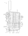
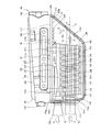
- FIG. 1 is an exploded perspective view of the fluid heating apparatus according to the first embodiment of the present invention.
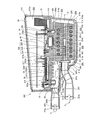
- FIG. 2 is a side view of the heater unit and the tank of the fluid heating apparatus according to the first embodiment, and is a view showing the tank in cross section.
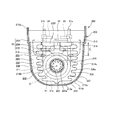
- FIG. 3 is a front view of the heater unit and the tank of the fluid heating apparatus according to the first embodiment, and is a view showing the tank in cross section. 4 is a cross-sectional view taken along the line IV-IV in FIG.
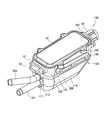
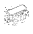
- FIG. 5 is a perspective view of a fluid heating apparatus according to the second embodiment of the present invention.
- FIG. 6 is an exploded perspective view of the fluid heating apparatus according to the second embodiment.
- FIG. 1 is an exploded perspective view of the fluid heating apparatus according to the first embodiment of the present invention.
- FIG. 2 is a side view of the heater unit and the tank of the fluid heating apparatus according to the first embodiment, and is a view showing the tank in cross section.
- FIG. 3 is a front view of the heater unit and the tank
- FIG. 7 is a side view of the fluid heating apparatus according to the second embodiment, and is a view showing a tank in section.
- FIG. 8 is a front view of the fluid heating apparatus according to the second embodiment, and is a view showing a tank in section.
- FIG. 9 is a perspective view of a fluid heating apparatus according to the third embodiment of the present invention.
- FIG. 10 is an exploded perspective view of the fluid heating apparatus according to the third embodiment.
- FIG. 11 is a longitudinal sectional view taken along the center line of the fluid heating apparatus according to the third embodiment.
- FIG. 12 is a front view of the fluid heating apparatus according to the third embodiment, and is a view showing a tank in section.
- the fluid heating device 1 is applied to a vehicle air conditioner (not shown) mounted on a vehicle such as EV (Electric Vehicle) or HEV (Hybrid Electric Vehicle).
- vehicle air conditioner not shown mounted on a vehicle such as EV (Electric Vehicle) or HEV (Hybrid Electric Vehicle).
- the fluid heating device 1 heats hot water as a fluid in order for the vehicle air conditioner to perform a heating operation.
- the fluid heating device 1 includes a tank 10 through which water flows, a heater unit 20 accommodated in the tank 10, a bus bar module 30 as an electrical component that supplies power to the heater unit 20,
- the control board 40 as a control part which controls operation
- the tank 10 is formed in a substantially rectangular parallelepiped shape.
- the tank 10 has a rectangular bottom surface 13, a wall surface 14 erected from the bottom surface 13, and an opening 15 that opens at an end of the wall surface 14 so as to face the bottom surface 13.
- the tank 10 has a first flow port 11 (supply port) to which hot water is supplied and a second flow port 12 (discharge port) from which hot water is discharged.
- the first flow port 11 and the second flow port 12 open in the same wall surface 14 of the tank 10 side by side.
- the fluid heating device 1 is disposed in the vehicle such that the second flow port 12 is positioned above the first flow port 11 when in use.
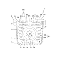
- the heater unit 20 includes a spiral heater 21 and a heating unit 22 formed so as to cover the periphery of the heater 21.
- a metal is die-cast around the heater 21, and a heating part 22 including the heater 21 and cast is formed.
- the heater unit 20 is formed integrally with a top plate portion 23 that closes the opening 15 of the tank 10 and forms the fluid chamber 4.
- the tank 10, the heater unit 20, and the cover 50 constitute a case 9 that forms the fluid chamber 4 and the electrical component chamber 5.
- a connecting portion 29 is formed between the heater unit 20 and the top plate portion 23, and the connecting portion 29 is formed integrally with the top plate portion 23 together with the heater unit 20. That is, the heater unit 20, the connecting portion 29, and the top plate portion 23 are integrally formed.
- the heater 21 has a pair of terminals 21a and 21b to which electric power is supplied via a bus bar module 30 from a power supply device (not shown) mounted on the vehicle.
- the heater 21 has a spiral heat generating part 21c (heat generating element) protruding into the tank 10 between the pair of terminals 21a and 21b.
- the heater 21 is a sheathed heater or a PTC (Positive Temperature Coefficient) heater that generates heat when energized.
- the heater 21 is preferably a sheathed heater in terms of cost.
- the heater 21 generates heat upon receiving a command from the control board 40 and heats the hot water flowing through the tank 10 via the heating unit 22.
- the heating unit 22 is formed smaller than the inner circumference of the heater 21 and formed through the through hole 25 penetrating along the central axis of the heater 21, and larger than the outer circumference of the heater 21. ) And an outer wall portion 26 facing the other.
- the heating unit 22 is formed of a metal having a lower melting point than that of the heater 21.
- the heater 21 is formed of stainless steel
- the heating unit 22 is formed of an aluminum alloy. The heating unit 22 transfers the heat generated by the heater 21 to the hot water and heats the hot water.
- the through hole 25 is formed inside the heat generating portion 21c wound in a spiral shape.
- the first flow port 11 of the tank 10 opens on an extension line of the through hole 25.
- the through hole 25 forms an inner peripheral flow path 27 (see FIG. 3) through which hot water supplied from the first flow port 11 flows.
- the through-hole 25 has a plurality of inner peripheral fins 25a that protrude to the inner periphery along the flow direction of the hot water.
- the inner peripheral fin 25a increases the heat transfer area in the inner peripheral flow path 27 as compared with the case where the inner peripheral fin 25a is not provided.
- the plurality of inner peripheral fins 25 a are formed at equiangular intervals over the entire circumference of the through hole 25.
- the outer wall portion 26 forms an outer peripheral channel 28 that guides the hot water flowing through the inner peripheral channel 27 to the second circulation port 12 between the outer wall 26 and the wall surface 14 of the tank 10.
- the outer wall portion 26 has a larger heat transfer area than the through hole 25.
- the outer peripheral channel 28 has a larger channel area than the inner peripheral channel 27.
- the outer wall portion 26 includes an outer wall main body 26a formed along the outer peripheral shape of the heater 21 and a plurality of outer peripheral fins 26b protruding from the outer wall main body 26a to the outer periphery along the flow direction of hot water.
- the outer wall main body 26a is formed so as to cover the outer side of the heat generating portion 21c wound in a spiral shape. Since the outer wall main body 26a is provided, the heater 21 and the hot water are not in direct contact with each other.
- the outer peripheral fin 26b increases the heat transfer area in the outer peripheral flow path 28 as compared with the case where the outer peripheral fin 26b is not provided.
- the outer peripheral fins 26 b extend substantially parallel to the bottom surface 13 of the tank 10 and the fluid chamber wall surface 16 (top surface) of the top plate portion 23.
- the outer peripheral fin 26 b is formed larger as it is closer to the fluid chamber wall surface 16 as compared with the central portion of the tank 10 in the height direction.
- the outer peripheral fins 26b are formed so as to face the pair of opposing wall surfaces 14 of the tank 10 with a predetermined interval.
- the heater unit 20 includes the heating unit 22 formed so as to cover the periphery of the heater 21.
- the heating unit 22 includes a through hole 25 formed smaller than the inner periphery of the heater 21 and an outer wall portion 26 formed larger than the outer periphery of the heater 21.
- the surface area of the heating unit 22 is a heat transfer area for exchanging heat with hot water, so the total surface area of the through holes 25 and the outer wall part 26 is the heat transfer area. Therefore, compared with the case where the heater 21 and warm water are made to contact directly, the heat transfer area for heat exchange with warm water can be enlarged.
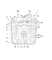
- the top plate portion 23 has an electrical equipment chamber wall surface 17 that forms an electrical equipment room 5 (control room) that houses electrical equipment parts.
- the top plate portion 23 is formed longer in the axial direction of the heater unit 20 than the opening 15 of the tank 10.
- a connector (not shown) for connecting the fluid heating device 1 to a power supply device or a host controller (not shown) mounted on the vehicle is provided at a portion of the top plate portion 23 that protrudes from the tank 10.
- the top plate 23 is welded to the outer peripheral edge of the opening 15 in a state where the heater unit 20 is inserted into the tank 10.
- the top plate portion 23 forms the fluid chamber wall surface 16 of the tank 10.
- the fluid chamber wall surface 16 faces the bottom surface 13 of the tank 10 substantially in parallel.
- the top plate 23 has a recess 24 a for attaching a bimetal switch 31 as a temperature switch, a recess 24 b for attaching a heater temperature sensor 32, and a recess 24 c for attaching a water temperature sensor 33. And are formed.
- a pair of IGBTs (Insulated Gate Bipolar Transistors) 34 and 35 abut on the top plate portion 23 as switching elements (electrical components).
- the top plate portion 23 has contact portions 17a and 17b that contact the IGBTs 34 and 35.
- the top plate portion 23 is formed with heat radiating fins 23b protruding from the fluid chamber wall surface 16 located on the back side of the contact portions 17a and 17b into the tank 10.
- a plurality of the radiating fins 23b are formed along the flow direction of the hot water around the radiating fins 23b, that is, along the flow direction of the hot water in the outer peripheral flow path 28, and the protruding amount from the top plate portion 23 is large along the flow direction of the hot water. Formed to be. Specifically, it is formed so that the amount of protrusion from the top plate portion 23 increases as it becomes closer to the second circulation port 12 side. Further, the heat radiating fins 23 b are formed so as not to contact the heating unit 22.
- each radiation fin 23b is extended along the direction orthogonal to the flow of warm water, you may extend each radiation fin 23b along the flow direction of warm water.
- the connecting portion 29 is provided between the heating portion 22 and the top plate portion 23 of the heater unit 20 as shown in FIG. 4, and extends along the axial direction of the heater unit 20 as shown in FIG. 4 is a cross-sectional view taken along the line IV-IV in FIG.
- the connecting portion 29 includes a neck portion 29 a that is connected to the upper portion of the heating portion 22, and a heat radiating portion 29 b that is provided between the neck portion 29 a and the top plate portion 23 and connects the neck portion 29 a and the top plate portion 23.
- the neck portion 29 a is formed such that the width of the neck portion 29 a is shorter than the width of the heater unit 20. By shortening the width of the neck portion 29a with respect to the heating portion 22, heat transfer from the heating portion 22 to the top plate portion 23 is suppressed.
- the heat radiating portion 29 b is formed so that the width of a part of the heat radiating portion 29 b is longer than the width of the neck portion 29 a.
- the heat radiating part 29b radiates the heat transmitted from the top plate part 23 to the hot water.
- the heat radiating part 29b radiates the heat transmitted from the neck part 29a to the hot water.
- the IGBTs 34 and 35 are connected to the vehicle power supply device via the bus bar module 30.
- the IGBTs 34 and 35 are connected to the control board 40 and perform a switching operation in response to a command signal from the control board 40.
- the IGBTs 34 and 35 control power supply to the heater unit 20 by a switching operation. Thereby, the heater unit 20 is adjusted to a desired temperature, and the hot water discharged from the second circulation port 12 is adjusted to the desired temperature.
- the IGBTs 34 and 35 generate heat by repeating the switching operation.
- the maximum temperature at which the IGBTs 34 and 35 can operate is higher than the temperature of hot water flowing in the tank 10. Therefore, the heat generated in the IGBTs 34 and 35 is radiated to the hot water flowing in the tank 10 through the heat radiation fins 23b and the heat radiation part 29b, and the IGBTs 34 and 35 are cooled.
- the bimetal switch 31 detects the temperature of the heater unit 20 and switches according to the detected temperature. Specifically, the bimetal switch 31 cuts off the supply of power to the heater unit 20 when the temperature of the heater unit 20 rises above the first set temperature. When the temperature of the heater unit 20 falls below a second set temperature that is lower than the first set temperature, the bimetal switch 31 is switched again so that the supply of power to the heater unit 20 is resumed. Also good.
- the heater temperature sensor 32 detects the temperature of the heater 21 in the heater unit 20.
- the heater temperature sensor 32 sends an electrical signal corresponding to the detected temperature of the heater 21 to the control board 40.
- the control board 40 stops the supply of power to the heater 21 when the temperature of the heater 21 detected by the heater temperature sensor 32 is higher than the set temperature.
- the water temperature sensor 33 detects the temperature of the hot water in the vicinity of the second circulation port 12 of the tank 10. That is, the water temperature sensor 33 detects the temperature of the heated hot water discharged from the tank 10.
- the water temperature sensor 33 is provided inside a protrusion 23 a (see FIGS. 2 and 3) that protrudes from the top plate 23 into the tank 10.
- the water temperature sensor 33 sends an electrical signal corresponding to the detected temperature of the hot water to the control board 40.
- the control board 40 controls the supply of electric power to the heater 21 so that the temperature of the hot water detected by the water temperature sensor 33 becomes a desired temperature.
- the bus bar module 30 is stacked on the top plate part 23.
- the bus bar module 30 is formed in a small rectangle as compared with the top plate portion 23.
- the bus bar module 30 is a conductive connection member formed of a metal plate capable of supplying electric power and electric signals.
- Control board 40 is stacked on top of bus bar module 30.
- the control board 40 is formed in a small rectangle as compared with the top plate part 23.
- the control board 40 is electrically connected to the bus bar module 30 and the IGBTs 34 and 35.
- the control board 40 controls the IGBTs 34 and 35 based on commands from the host controller.
- the cover 50 is provided on the upper part of the control board 40.
- the cover 50 is formed in the substantially same outer peripheral shape as the top plate portion 23.
- the cover 50 is welded to the outer peripheral edge of the top plate portion 23.
- the cover 50 seals the internal space between the top plate portion 23.
- the fluid heating apparatus 1 for heating hot water has a heater 21 having a heat generating portion 21c that generates heat when energized, electrical components such as IGBTs 34 and 35 for controlling energization of the heater 21, and an opening 15.
- the tank 10 that accommodates the heater 21, the top plate part 23 that forms the fluid chamber 4 through which the warm water flows by closing the opening 15 of the tank 10, the first flow port 11 that allows the warm water to flow through the fluid chamber 4, and A second distribution port 12.
- Electrical components such as IGBTs 34 and 35 are configured to be provided on the outer side (back side) of the fluid chamber 4 along the top plate portion 23.
- first flow port 11 and the second flow port 12 are arranged on the same side (left side in FIG. 2) with respect to the heater 21, and the first flow port 11 is arranged to face the heat generating part 21 c of the heater 21.
- the second flow port 12 is arranged between the first flow port 11 and the top plate portion 23 when viewed from the extending direction of the heat generating portion 21 c of the heater 21.
- the hot water guided by the first flow port 11 circulates around the heat generating portion 21 c of the heater 21 (inside and outside), whereby the heat of the heater 21 is transmitted to the hot water.
- the hot water guided by the second flow port 12 circulates along the top plate part 23, so that heat generated in the electrical components such as the IGBTs 34 and 35 is efficiently transferred to the hot water via the top plate part 23. Well communicated. Therefore, electrical components such as the IGBTs 34 and 35 can be sufficiently cooled.
- hot water is supplied from the outside of the tank 10 to the fluid chamber 4 through the first circulation port 11, and is discharged from the fluid chamber 4 to the outside of the tank 10 through the second circulation port 12.
- hot water may be supplied from the outside of the tank 10 to the fluid chamber 4 through the second circulation port 12 and discharged from the fluid chamber 4 to the outside of the tank 10 through the first circulation port 11.
- the heater 21 is provided inside the cylindrical heating unit 22. Not only this but the heating part 22 may be abolished and you may comprise so that the heater 21 may heat warm water directly.
- the fluid heating apparatus 1 further includes a heating unit 22 that is formed so as to cover the heater 21 and heats the hot water, and the heating unit 22 is formed integrally with the top plate unit 23.
- the hot water guided by the first flow port 11 flows around the heating unit 22, whereby the heat of the heater 21 is transmitted to the hot water via the heating unit 22.
- the surface area of the heating unit 22 is a heat transfer area for exchanging heat with hot water. Therefore, compared with the case where the heater 21 and warm water are made to contact directly, the heat transfer area for heat exchange with warm water can be enlarged. Therefore, the heat transfer efficiency that the heater 21 heats the hot water is improved.
- the heat generated by the heater 21 is also transmitted to the top plate part 23 through the heating part 22.
- the hot water guided by the second circulation port 12 flows along the top plate portion 23, whereby the heat of the top plate portion 23 is efficiently transmitted to the hot water.
- the temperature rise of electrical components, such as the top-plate part 23, IGBT34,35, and the water temperature sensor 33, is suppressed.
- the fluid heating device 1 can achieve both the improvement of the heat transfer efficiency of the heater 21 heating the hot water and the improvement of the heat resistance of the electrical components such as the IGBTs 34 and 35 and the water temperature sensor 33. .
- the heating part 22 and the top plate part 23 are integrally formed, assembly work is facilitated.
- the fluid heating device 1 includes a neck portion 29 a having a width shorter than that of the heating unit 22 in the connecting unit 29 that connects the heating unit 22 and the top plate unit 23.
- heat transfer from the heating unit 22 to the top plate part 23 can be suppressed, the temperature of the top plate part 23 is suppressed from increasing, and the IGBT 34 that contacts the top plate part 23. , 35 can be prevented from increasing.
- the heat transfer from the heating part 22 to the top plate part 23 the heat transfer from the heating part 22 to other than the warm water can be suppressed, and the heating part 22 caused by the heat transfer to other than the warm water can be suppressed.
- Temperature drop can be suppressed. Therefore, the heat generation in the heater 21, that is, the energization amount to the heater 21, can be suppressed, and the power consumption in the heater 21 can be suppressed.
- the fluid heating apparatus 1 includes a heat radiating portion 29b having a width wider than that of the neck portion 29a between the neck portion 29a and the top plate portion 23.
- the heat transfer area with the hot water in the heat radiating part 29b can be increased, and the heat radiation amount of heat transferred from the heating part 22 through the neck part 29a can be increased. Therefore, heat transfer from the heating unit 22 to the top plate portion 23 can be suppressed, the temperature of the top plate portion 23 is suppressed from being increased, and the temperatures of the IGBTs 34 and 35 that are in contact with the top plate portion 23 are increased. This can be suppressed.
- the amount of heat dissipated from the top plate portion 23 to the heat radiating portion 29b can be increased, the temperature of the top plate portion 23 is suppressed from increasing, and the IGBTs 34 and 35 that are in contact with the top plate portion 23 can be prevented. It can suppress that temperature becomes high.
- top plate portion 23 is provided with heat radiation fins 23b protruding into the fluid chamber 4 from the fluid chamber wall surface 16 on the back side of the contact portions 17a and 17b with which electrical components such as the IGBTs 34 and 35 are brought into contact.
- the heat generated in the IGBTs 34, 35 and the like can be radiated to the hot water via the radiation fins 23b, and it is not necessary to provide a separate mechanism for cooling the IGBTs 34, 35, and the fluid heating device 1 can be downsized. it can.
- heat radiation fins 23b are provided so as not to contact the heating unit 22.
- the fluid heating apparatus 1 can prevent that the heat which generate
- the radiating fin 23b increases the amount of protrusion from the fluid chamber wall surface 16 along the flow direction of the warm water around the radiating fin 23b.
- the amount of heat radiation from the heat radiation fins 23b to the hot water can be increased even on the downstream side in the flow direction of the hot water in the outer peripheral flow path 28, and the IGBTs 34 and 35 can be further cooled. .
- the tank 110 of the fluid heating apparatus 100 has a second wall surface 114 b that is inclined with respect to the center line O of the first flow port 111.
- the hot water supplied to the fluid chamber 104 from the first circulation port 111 is configured to be smoothly guided to the top plate portion 123 (fluid chamber wall surface 116) by the second wall surface 114b.
- the fluid heating apparatus 100 is configured to connect a tank 110 forming a fluid chamber 104 through which water flows, a heater unit 120 accommodated in the tank 110, and various electrical components.
- the bus bar module 30, a control board 40 as a control unit for controlling the operation of the heater unit 120, and a cover 50 that covers the bus bar module 30 and the control board 40 are provided.
- the tank 110 is formed in a boat shape.
- the tank 110 has a bottom surface 113, four wall surfaces 114 a, 114 b, 114 c, 114 d (see FIGS. 7 and 8) that are erected from the bottom surface 113, and end portions of the wall surfaces 114 a, 114 b, 114 c, 114 d. And an opening 115 that opens to face the bottom surface 113.
- the wall surfaces 114a, 114b, 114c, and 114d are formed to be inclined with respect to the vertical line (reference line) so as to face upward.
- the first wall 114a of the tank 110 has a first circulation port 111 (supply port) for supplying warm water to the fluid chamber 104 from the outside, and a second circulation port 112 (discharge port) for discharging warm water from the fluid chamber 104 to the outside. And open side by side.
- the fluid heating device 100 is mounted on the vehicle such that the second flow port 112 is positioned above the first flow port 111.
- the present invention is not limited to this, and the fluid heating device 100 may be mounted on the vehicle such that the second circulation port 112 and the first circulation port 111 are aligned in the horizontal direction.
- the second wall surface 114b of the tank 110 is formed so as to be opposed to the first wall surface 114a and inclined at an angle ⁇ with respect to the center line O of the first flow port 111 (see FIG. 7).
- the angle at which the second wall surface 114b is inclined with respect to the vertical line (reference line) is formed larger than that of the other wall surfaces 114a, 114c, 114d.
- the base end portion 157a of the supply pipe 157 is inserted into the first flow port 111.
- a pipe (not shown) for guiding the supplied hot water is connected to the supply pipe 157 protruding from the tank 110.
- the base end portion 158a of the discharge pipe 158 is inserted into the second circulation port 112.
- a pipe (not shown) for guiding the hot water to be discharged is connected to the discharge pipe 158 protruding from the tank 110.
- the heater unit 120 includes an electrothermal heater (hereinafter simply referred to as “heater”) 21 that generates heat, and a heating unit 122 that is formed so as to cover the heater 21.
- a top plate portion 123 (lid) that closes the opening 115 of the tank 110 and a connecting portion 124 that connects the heating unit 122 and the top plate portion 123 are provided.
- the heating part 122, the connecting part 124, and the top plate part 123 are integrally formed.
- the heater 21 has a spiral heat generating part 21 c cast into the heating part 122 and a pair of terminals 21 a and 21 b protruding upward from the top plate part 123. Note that the heat generating portion 21c is not spiral, and may be formed so as to reciprocate within the heating portion 122, for example.
- the heating part 122 is formed with a small diameter compared with the inner periphery of the heat generating part 21c and penetrates along the center of the heat generating part 21c, and is formed with a large diameter compared with the outer periphery of the heat generating part 21c.
- An outer wall 126 facing the third wall surface 114c and the fourth wall surface 114d, a first end wall portion 127 facing the first wall surface 114a, and a second end wall portion 128 facing the second wall surface 114b. Have.
- the through-hole 125 is formed inside the heat generating portion 21c wound in a spiral shape.
- the first flow port 111 of the tank 110 opens on the center line O of the through hole 125.
- the through hole 125 forms an inner peripheral flow path 252 (see FIG. 8) through which hot water supplied from the first flow port 111 flows.
- the outer wall portion 126 forms an outer peripheral flow path 154 between the bottom surface 113 of the tank 110, the third wall surface 114c, the fourth wall surface 114d, and the fluid chamber wall surface 116 of the top plate portion 123.
- the outer peripheral channel 154 communicates with the inner peripheral channel 152 and guides the hot water flowing from the inner peripheral channel 152 to the second circulation port 112.
- the outer wall 126 has a larger heat transfer area than the through-hole 125. Further, the outer peripheral channel 154 has a larger channel area than the inner peripheral channel 152.
- the first end wall portion 127 is opposed to the first wall surface 114a with an interval, and forms a first end flow channel 151 between the first end wall portion 127 and the first wall surface 114a.
- the first end flow channel 151 allows hot water to continuously flow through the first flow port 111, the second flow port 112, the inner peripheral flow channel 152, and the outer peripheral flow channel 154.
- an annular inlet portion 145 in which the through hole 125 is opened is formed in the first end wall portion 127 of the heating portion 122.
- the base end portion 157a of the supply pipe 157 protrudes from the first wall surface 114a into the tank 110, and is disposed at an opening in the through hole 125 with respect to the inlet portion 145 (first end wall portion 127). Hot water supplied from the supply pipe 157 is guided to the inner peripheral flow path 152 through the first end flow path 151.
- the base end portion 157a of the supply pipe 157 may be inserted into the inlet portion 145, and the supply pipe 157 may be connected to the through hole 125. In this case, the entire amount of hot water supplied from the supply pipe 157 is guided to the inner peripheral flow path 152.
- the second end wall portion 128 of the heating unit 122 faces the second wall surface 114b with an interval, and forms a second end channel 153 between the second wall surface 114b.
- the second end channel 153 allows hot water to flow continuously through the inner circumferential channel 252 and the outer circumferential channel 154.
- the fluid chamber 104 formed inside the tank 110 includes a first end channel 151, an inner circumferential channel 152, an outer circumferential channel 154, and a second end channel 153. As shown in FIG. 7, in the first flow port 111, the center line O of the fluid chamber 104 is disposed below the center line H of the fluid chamber 104.
- the heater unit 120 is welded to the outer peripheral edge of the opening 115 in a state where the heating unit 122 is disposed in the tank 110 and the top plate 123 is fitted in the opening 115.
- the top plate portion 123 has a fluid chamber wall surface 116 (heat dissipating wall surface) facing the outer peripheral flow path 154.
- the fluid chamber wall surface 116 extends substantially parallel to the center line O.
- the fluid chamber wall 116 faces the outer wall 126 of the heating unit 122 with a space, and forms a part of the outer peripheral flow path 154 with the outer wall 126.
- the fluid chamber wall 116 is formed to face the first end channel 251, the outer peripheral channel 154, and the second end channel 153.
- the tank 110 and the top plate portion 123 constitute a case 109.
- the case 109 accommodates the heating unit 122 (heater 21) and forms a fluid chamber 104 (heating channel) through which hot water flows between the case 109 and the heating unit 122.
- a box-shaped electrical component chamber wall portion 129 (housing) opened upward is formed on the top plate portion 123.
- a pair of mounting seats 167 and 168 are formed on both sides of the electrical equipment chamber wall portion 129.
- the fluid heating device 100 is attached to the vehicle via brackets (not shown) fastened to the attachment seats 167 and 168, respectively.
- the electrical component chamber wall portion 129 includes an electrical component chamber wall surface 117 (bottom wall surface) located on the back side of the fluid chamber wall surface 116, a side wall surface 118 erected from the electrical component chamber wall surface 117, and an opening opened at the end of the side wall surface 118. Part 119.
- the opening 119 of the electrical equipment chamber wall 129 is closed by the cover 50.
- An electrical room 160 (control room) is formed between the electrical room wall 129 and the cover 50.
- a plurality of boss portions 165 are formed on both side portions of the electrical equipment chamber wall portion 129.
- the cover 50 is fastened to the electrical component chamber wall portion 129 by a bolt (not shown) that is screwed into the boss portion 165.
- the bus bar module 30 and the control board 40 are accommodated in the electrical compartment 160.
- Mounting seats 161 and 162 are formed at both ends of the electrical equipment chamber wall portion 129, respectively.
- a connector 63 for connecting a signal line (not shown) for guiding an electrical signal is attached to the mounting seat 161.
- a connector 64 for connecting a power supply line (not shown) for supplying power is attached to the mounting seat 162.
- the electrical equipment chamber wall surface 117 has contact portions 117a and 117b with which the pair of IGBTs 34 and 35 abut.
- the bus bar module 30 is formed with receiving holes 36 and 37 for receiving the IGBTs 34 and 35.
- the IGBTs 34 and 35 are in contact with the electrical equipment chamber wall surface 117 and are attached to the electrical equipment chamber wall portion 129 via the plate 38.
- the center portion of the plate 38 is fastened to the top plate portion 123 via bolts 39, and the IGBTs 34 and 35 are pressed against the electrical equipment wall surface 117 by both ends thereof.
- the bolt 39 passes through the hole 49 of the bus bar module 30 and is screwed into a screw hole (not shown) of the top plate portion 123.
- the top plate 123 has a recess 123 a for attaching the bimetal switch 31 as a temperature switch, a recess (not shown) for attaching the heater temperature sensor 32, and a water temperature sensor 33.
- a recess (not shown) is formed.
- the water temperature sensor 33 is provided inside a protruding portion 123g (see FIGS. 7 and 8) protruding from the top plate portion 123 to the fluid chamber 104.
- the top plate portion 123 is formed with heat radiating fins 123f that protrude toward the fluid chamber 104 from the fluid chamber wall surface 116 located on the back side of the location where the IGBT 34 abuts.
- a plurality of heat dissipating fins 123f are formed facing the hot water flow direction in the outer peripheral flow path 154.
- the heat radiating fins 123f are formed to face the second end flow path 153 and the outer peripheral flow path 154.
- the heat dissipating fins 123f are formed so as to extend in a direction substantially orthogonal to the center line O and to be arranged at a certain interval in the center line O direction.
- Each radiating fin 123f is formed with a certain amount of protrusion (height) from the fluid chamber wall surface 116.
- the fluid chamber wall surface 116 and the second wall surface 114b are inclined with each other, and a tip end portion 104a of the tapered fluid chamber 104 (second end flow path 153) is formed therebetween.
- the hot water supplied through the supply pipe 157 as indicated by the arrow A is guided to the inner peripheral flow path 152 through the first end flow path 151 of the fluid chamber 104 and passes through the inner peripheral flow path 152 as indicated by the arrow B.
- the hot water is heated by heat exchange with the inner periphery of the through hole 125 in which the inner peripheral fin 125a is formed. This hot water flow is rectified by the inner peripheral fins 125a.
- the hot water that has passed through the inner peripheral flow path 152 flows into the second end flow path 153 as indicated by an arrow C, changes direction along the second wall surface 114b, and is guided to the outer peripheral flow path 154 around the heating unit 122. Since the second wall surface 114 b is inclined so as to face the fluid chamber wall surface 116, the force of the warm water turned back in the second end flow path 153 increases toward the fluid chamber wall surface 116 as indicated by an arrow D. Thereby, the flow rate of the hot water flowing along the fluid chamber wall surface 116 as indicated by the arrow F in the outer peripheral flow path 154 is higher than the flow rate of the hot water flowing along the outer peripheral fin 126a as indicated by the arrow E.
- the hot water flowing along the fluid chamber wall surface 116 in the second end channel 153 and the outer peripheral channel 154 is heated by heat exchange with the fluid chamber wall surface 116 and each radiating fin 123f.
- the hot water flowing around the heating part 122 is heated by heat exchange with the outer wall part 126 and the outer peripheral fin 126a. This flow of warm water is rectified by the peripheral fin 126a.
- the hot water that has circulated through the outer peripheral flow path 154 is discharged from the discharge pipe 158 of the second flow port 112 through the first end flow path 151 as indicated by an arrow G.
- the tank 110 of the fluid heating apparatus 100 includes a first wall surface 114a in which the first flow port 111 and the second flow port 112 are opened, and a second wall surface 114b that faces the first wall surface 114a with the heat generating portion 21c interposed therebetween. .
- the second wall surface 114b is inclined with respect to the center line O of the first flow port 111 so as to guide the hot water supplied from the first flow port 111 to the fluid chamber 104 to the top plate portion 123 (fluid chamber wall surface 116). It was.
- the hot water flows into the fluid chamber 104 from the first flow port 111, turns back the fluid chamber 104 along the second wall surface 114b, and flows out from the second flow port 112.
- the hot water that turns back the fluid chamber 104 along the second wall surface 114b is guided to the fluid chamber wall surface 116 along the second wall surface 114b that is inclined so as to face the fluid chamber wall surface 116, as indicated by an arrow D in FIG.
- the flow velocity of the hot water flowing along the fluid chamber wall surface 116 is increased.
- the heat of the IGBTs 34 and 35 is urged to be radiated from the fluid chamber wall surface 116 to the hot water flowing through the fluid chamber 104. Therefore, the IGBTs 34 and 35 are sufficiently cooled.
- the angle ⁇ at which the second wall surface 114b is inclined with respect to the center line O is arbitrarily set.
- the flow rate of the hot water flowing along the fluid chamber wall surface 116 is adjusted in the fluid chamber 104 according to the angle ⁇ .
- the second circulation port 112 is configured to be opened side by side with the first circulation port 111 and to be disposed at a position closer to the fluid chamber wall surface 116 than the first circulation port 111.
- the second flow port 112 is closer to the fluid chamber wall surface 116 than the first flow port 111, so that the flow rate of warm water toward the second flow port 112 in the fluid chamber 104 (outer peripheral flow path 154). Is increased in the region along the fluid chamber wall 116. Therefore, the IGBTs 34 and 35 are sufficiently cooled.
- the first flow port 111 has a configuration in which the center line O is disposed at a position farther from the top plate portion 123 (fluid chamber wall 116) than the center (center line H) of the case 109.
- the flow rate of the warm water flowing from the first circulation port 111 is increased in a lower region away from the fluid chamber wall surface 116, whereby the flow rate of the warm water toward the second circulation port 112 is increased. In the upper region along 116. Therefore, the IGBTs 34 and 35 are sufficiently cooled.
- the second wall surface 114 b is inclined with respect to the top plate portion 123 (fluid chamber wall surface 116), and the front end portion 104 a of the fluid chamber 104 is formed between the second wall surface 114 b and the top plate portion 123.
- the tip portion 104a of the tapered fluid chamber 104 is formed between the fluid chamber wall surface 116 and the second wall surface 114b of the top plate portion 123 that are inclined to each other, whereby the fluid chamber 104 (second end) is formed.
- a large area of the fluid chamber wall 116 facing the flow path 153) is ensured. Therefore, the IGBTs 34 and 35 are sufficiently cooled.
- case 109 is configured to have a heat radiating fin 123f protruding from the fluid chamber wall 116 to the fluid chamber 104.
- the heat generated by the IGBTs 34 and 35 is radiated to the hot water through the radiation fins 123f. This prompts the IGBTs 34 and 35 to be cooled via the case 109.
- heat dissipating fins 123f are configured to extend in a direction substantially orthogonal to the center line O of the first flow port 111.
- each radiating fin 123f is formed so that the amount of protrusion from the fluid chamber wall surface 116 becomes equal. Not only this but each radiation fin 123f may form so that the protrusion amount from the fluid chamber wall surface 116 may become large sequentially from the 2nd wall surface 114b to the 1st wall surface 114a. In this case, each of the radiating fins 123f has a protruding amount from the wall surface 116 of the fluid chamber that increases along the flow direction of the warm water in the outer peripheral flow path 154. A sufficient amount of heat radiation to the hot water is ensured, and cooling of the IGBTs 34 and 35 is promoted.
- the heating unit 122 includes a through hole 125 that forms an inner peripheral flow path 252 through which hot water supplied from the first flow port 111 flows, and an outer peripheral flow path 154 through which hot water flows from the through hole 125 toward the second flow port 112. And an outer wall portion 126 to be formed.
- connecting portion 124 is arranged between the portion (radiating fin 123f) located on the back side of the contact portions 117a and 117b in the fluid chamber wall surface 116 and the second circulation port 112.
- the warm water before passing around the connecting portion 124 in the outer peripheral flow path 154 smoothly flows along the portion located on the back side of the contact portions 117a and 117b in the fluid chamber wall surface 116.
- the flow rate of hot water flowing along 116 is increased.
- the heat of the IGBTs 34 and 35 is urged to be radiated from the fluid chamber wall surface 116 to the hot water flowing through the fluid chamber 104. Therefore, the IGBTs 34 and 35 are sufficiently cooled.
- the second wall surface 114b is formed in a planar shape extending smoothly without a step as a guide portion for directing the flow of hot water toward the fluid chamber wall surface 116.
- the rib which protrudes from the 2nd wall surface 114b as a guide part is formed, and it is good also as a structure by which the flow of warm water is directed to the fluid chamber wall surface 116 by the rib.
- the hot water supplied from the first circulation port 111 flows through the inner circumferential channel 152, then flows through the outer circumferential channel 154, and is discharged from the second circulation port 112.
- the hot water supplied from the first circulation port 111 may flow through the outer circumferential channel 154 and then flow through the inner circumferential channel 152 and be discharged from the second circulation port 112.
- the heater 21 is provided inside the cylindrical heating unit 122. Not only this but the heating part 122 may be abolished and you may comprise so that the heater 21 may heat warm water directly.
- FIGS. Next, a third embodiment of the present invention will be described with reference to FIGS. Below, it demonstrates centering on a different point from the said 1st Embodiment or the said 2nd Embodiment, and the same structure as the fluid heating apparatus 1 which concerns on the said 1st Embodiment, or the fluid heating apparatus 100 which concerns on the said 2nd Embodiment. Are denoted by the same reference numerals, and description thereof is omitted.
- the fluid heating apparatus 200 includes a heater accommodating portion 208 that accommodates the heater 21 in a tank 210, and a bulging portion 259 that extends from the heater accommodating portion 208 along the top plate portion 223. In the bulging portion 259, the hot water flows along the top plate portion 223, so that the heat of the top plate portion 223 is quickly and efficiently transmitted to the hot water.
- the tank 210, the heater unit 220, and the cover 50 constitute a case 209.
- the case 209 is provided with a fluid chamber 204 in which the heater 21 is accommodated and hot water flows, and an electrical component chamber 205 (control chamber) in which electrical components are accommodated. .
- the heater unit 220 includes an electric heater (hereinafter simply referred to as a “heater”) 21, a block-shaped heating unit 222 formed so as to cover the heater 21, and the fluid chamber 204 between the tank 210. And a connecting portion 224 that connects the heating portion 222 and the top plate portion 223 to each other.
- the heating part 222, the connecting part 224, and the top plate part 223 are integrally formed.
- the heater 21 has a spiral heat generating part 21 c cast into the heating part 222 and a pair of terminals 21 a and 21 b protruding upward from the top plate part 223. Note that the heat generating portion 21c is not spiral, and may be formed to reciprocate within the heating portion 222, for example. As shown in FIG. 11, a straight line passing through the central portion of the heater 21 (heat generating portion 21 c) is defined as a center line O of the heater 21.
- the heating part 222 includes a through-hole 225 that penetrates the inside of the heat generating part 21c, an outer wall part 226 formed around the heat generating part 21c, a first end wall part 227 formed on one end side of the heat generating part 21c, And a second end wall portion 228 formed on the other end side of the heat generating portion 21c.
- the outer wall portion 226 has a larger heat transfer area than the through hole 225.
- the heating unit 222 has a plurality of inner peripheral fins 225a protruding from the inner periphery of the through hole 225.
- the plurality of inner peripheral fins 225a extend along the hot water flow direction, and are formed at equiangular intervals over the entire circumference of the through hole 225.
- the inner peripheral fin 225a increases the heat transfer area in the inner peripheral flow path 52 as compared with the case where the inner peripheral fin 225a is not provided.
- the outer wall portion 226 has a plurality of outer peripheral fins 226a extending along the flow direction of the hot water.
- the outer peripheral fin 226a increases the heat transfer area in the outer peripheral flow path 54 as compared with the case where the outer peripheral fin 226a is not provided.
- the tank 210 has a fluid chamber wall portion 210b that forms the fluid chamber 204, and an electrical component chamber wall portion 210a that forms the electrical component chamber 205.
- the electrical equipment chamber wall part 210a is not limited to the structure formed integrally with the tank 210, and may be formed integrally with the heater unit 220.
- an opening 215 of the fluid chamber wall 210b is formed in the tank 210.
- the opening 215 is closed by the top plate 223.
- the top plate part 223 is joined to the tank 210 by welding or the like.
- the top plate portion 223 is a partition wall that partitions the fluid chamber 204 and the electrical component chamber 205.
- an opening 219 of the electrical equipment chamber wall 210a is formed in the upper part of the tank 210.
- the opening 219 is closed by the cover 50.
- the cover 50 is fastened to the electrical component chamber wall portion 210a by a bolt (not shown) that is screwed into the boss portion 265 of the electrical component chamber wall portion 210a.
- the mounting seats 261 and 262 are formed on the sides of the tank 210, respectively.
- a connector 63 is attached to the attachment seat 261.
- a connector 64 is attached to the attachment seat 262.
- the top plate 223 is formed with a recess 223 a for attaching the bimetal switch 31, a recess 223 b for attaching the heater temperature sensor 32, and a hole 223 c for attaching the water temperature sensor 33. Is done.
- the bimetal switch 31 is pressed by the plate 48 fastened to the top plate portion 223 and is held in contact with the bottom of the recess 223a.
- the water temperature sensor 33 is housed in a bottomed cylindrical cap 43 attached to the top plate 223 and is held in contact with the bottom of the cap 43.
- An annular space is provided between the outer periphery of the water temperature sensor 33 and the inner periphery of the cap 43.
- the cap 43 is provided so that the outer periphery of the opening end is inserted into the hole 223 c of the top plate 223, and the outer periphery and the bottom thereof face the fluid chamber 204.
- the cap 43 is disposed between the IGBTs 34 and 35 and the second circulation port 212 (discharge port), and protrudes upstream of the second circulation port 212 in the fluid chamber 204.
- the IGBTs 34 and 35 are pressed by a plate 38 fastened to the top plate portion 223 and are held in contact with the top plate portion 223.
- the top plate portion 223 has an electrical component chamber wall surface 217 that forms the electrical component chamber 205.
- the electrical equipment chamber wall surface 217 has contact portions 217 a and 217 b that contact the IGBTs 34 and 35.
- the top plate portion 223 has a fluid chamber wall surface 216 (top surface) that forms the fluid chamber 204.
- the fluid chamber wall 210b of the tank 210 extends along the heater housing wall 210c that forms a heater housing 208 (flow path) around the heating unit 222 (heater 21), and the heater housing 208 along the top plate 223. And a bulging wall portion 210d that forms a bulging portion 259 (flow path) that bulges.
- a first circulation port 211 supply port
- a second circulation port 212 discharge port through which warm water is discharged to the outside opens at one end of the bulging wall portion 210d.
- the first circulation port 211 and the second circulation port 212 are arranged on one end side (left side in FIG. 11) of the heater unit 220.
- the first flow port 211 and the through hole 225 of the heating unit 222 are arranged so as to be aligned in the axial direction in which the center line O of the heater 21 extends.
- the second circulation port 212 is disposed at a position closer to the top plate portion 223 than the first circulation port 211.
- the second flow port 212 is offset in a direction (downward) away from the heater unit 220 in the axial direction in which the center line O of the heater 21 extends with respect to the first flow port 211. Thereby, in the bulging part 259 of the fluid chamber 204, the hot water from the heater accommodating part 208 toward the second circulation port 212 circulates along the top plate part 223.
- the fluid chamber wall portion 210b of the tank 210 forms a fluid chamber 204 by the first wall portion 214a to the fifth wall portion 214e, the first bottom portion 213a, and the second bottom portion 213b.
- the first wall portion 214a to the fifth wall portion 214e are formed to be inclined with respect to the vertical line (reference line) so as to face upward.
- the first bottom portion 213a and the second bottom portion 213b extend in a substantially horizontal direction from the upper and lower ends of the first wall portion 214a (step).
- the heater accommodating unit 208 is provided outside the heating unit 222, the first end channel 251 and the second end channel 253 provided at both ends of the heating unit 222, the inner circumferential channel 252 provided inside the heating unit 222, and the heating unit 222. And an outer peripheral channel 254.
- the first end channel 251 is formed between the first end wall portion 227 of the heating unit 222 and the first wall portion 214a of the tank 210.
- a first circulation port 211 is opened in the first end channel 251.
- the supply pipe 57 is inserted into the first distribution port 211.
- a pipe (not shown) through which hot water flows is connected to the supply pipe 57 protruding from the tank 210.
- a concave space 255 formed in a concave shape by the heater accommodating wall portion 210c and the bulging wall portion 210d is formed on the outside of the tank 210.
- the supply pipe 57 is disposed along the bulging wall portion 210d and fits in the concave space 255.
- the supply pipe 257 includes a base end portion 257a inserted into the first flow port 211, a bent portion 257c that bends away from the base end portion 257a with respect to the bulging wall portion 210d, and a discharge pipe 58. And a leading end portion 257b.
- the supply pipe 257 is bent in a crank shape and is disposed so as to extend with a gap with respect to the bulging wall portion 210d.
- the first end wall portion 227 of the heating portion 222 is formed with an annular inlet portion 245 that opens on the extension of the through hole 225.
- the base end portion 257a of the supply pipe 257 protrudes from the first wall portion 214a into the tank 210, and is inserted into the inlet portion 245 (first end wall portion 227) of the through hole 225 with an annular gap. Hot water supplied from the supply pipe 257 is guided to the first end flow path 251 and the inner peripheral flow path 252.
- the base end portion 257a of the supply pipe 257 may be inserted into the inlet portion 245 without a gap, and the supply pipe 257 may be connected to the through hole 225. In this case, the entire amount of hot water supplied from the supply pipe 257 is guided to the inner peripheral flow path 252.
- the inner peripheral flow path 252 is formed by the through hole 225 of the heating unit 222.
- the through hole 225 is formed around the center line O of the first flow port 211.
- the inner peripheral flow path 252 extends on the center line O (on the extension line) of the first flow port 211.
- the second end channel 253 is formed between the second end wall portion 228 of the heating unit 222 and the second wall portion 214b of the tank 210.
- the second wall 214b is formed so as to face the first wall 214a through the heating part 222 of the heater unit 220.
- the hot water flowing out from the inner peripheral channel 252 flows into the outer peripheral channel 254 through the first end channel 251.
- the outer peripheral channel 254 includes an outer wall portion 226 of the heating unit 222, a first bottom portion 213a of the tank 210, a third wall portion 214c, a fourth wall portion 214d, and a fluid chamber wall surface 216 of the top plate portion 223. Formed between.
- the flow path area of the outer peripheral flow path 254 orthogonal to the center line O is larger than that of the inner peripheral flow path 252.
- the third wall portion 214c and the fourth wall portion 214d of the tank 210 are formed so as to face each other.
- a heating unit 222 is disposed between the third wall portion 214c and the fourth wall portion 214d.
- the bulging portion 259 includes an upper portion of the third wall portion 214c of the tank 210, an upper portion of the fourth wall portion 214d, a second bottom portion 213b, a fifth wall portion 214e, and a fluid chamber wall surface 216 of the top plate portion 223. , Formed between.
- the cross-sectional shape of the bulging portion 259 is a flat shape along the fluid chamber wall surface 216 of the top plate portion 223.
- the bulging portion 259 is formed such that the flow path width L1 in the width direction along the fluid chamber wall surface 216 is larger than the flow path height L2 with respect to the fluid chamber wall surface 216.
- the channel area of the bulging portion 259 orthogonal to the center line O is smaller than that of the outer peripheral channel 254.
- the fifth wall 214e is formed so as to face the second wall 214b via the heating part 222 of the heater unit 220 at a position away from the heater unit 220 with respect to the first wall 214a.
- a second bottom 213b extends between the lower end of the fifth wall 214e and the upper end of the first wall 214a.
- a second circulation port 212 (discharge port) for discharging hot water from the fluid chamber 204 to the outside opens in the fifth wall portion 214e.
- the base end portion 258a of the discharge pipe 258 is inserted into the second circulation port 212.
- a pipe (not shown) for guiding the hot water to be discharged is connected to the discharge pipe 258 protruding from the tank 210.
- the cross-sectional shape of the second circulation port 212 is formed in a substantially oval shape. Similar to the bulging portion 259, the second circulation port 212 has a flat shape along the top plate portion 223.
- the fluid chamber wall surface 216 of the top plate portion 223 extends in a substantially horizontal direction substantially parallel to the center line O.
- the top plate portion 223 forms a bulging portion 259 between the top plate heater housing portion 223d that forms the heater housing portion 208 (the outer peripheral flow path 254) and the bulging wall portion 210d.
- the top plate bulging portion 223e is formed with heat radiating fins 223f protruding from the fluid chamber wall surface 216 toward the bulging portion 259.
- the radiation fin 223f protrudes from the fluid chamber wall surface 216 located on the back side of the contact portions 217a and 217b with which the IGBT 34 contacts.
- a plurality of heat dissipating fins 223f are formed facing the hot water flow direction in the outer peripheral flow path 254.
- the heat radiating fins 223f protrude from the fluid chamber wall surface 216 to the second end flow path 253 and the bulging portion 259 with a certain amount of protrusion (height).
- Each of the heat dissipating fins 223f extends in a direction substantially orthogonal to the center line O, and is formed so as to be arranged at a constant interval in the center line O direction.
- each radiation fin 223f may be formed so that the amount of protrusion from the fluid chamber wall surface 216 increases along the flow direction of the hot water.
- each radiation fin 223f is not limited to the above-described configuration, and may be extended in a direction substantially parallel to the center line O.
- the hot water supplied through the supply pipe 257 is guided to the inner peripheral flow path 252 through the first end flow path 251 as indicated by an arrow A in FIG. Circulates the circumferential flow path 252.
- the hot water is heated by heat exchange with the inner periphery of the through hole 225 in which the inner peripheral fin 225 a is formed.
- the hot water flowing out from the inner peripheral flow path 252 to the second end flow path 253 changes direction along the second wall portion 214b and flows through the outer peripheral flow path 254 around the heating section 222 as indicated by an arrow C. .
- the outer peripheral flow path 254 hot water is heated by heat exchange with the outer wall portion 226 in which the outer peripheral fin 226a is formed.
- the hot water flowing through the outer peripheral flow path 254 and the first end flow path 251 flows through the bulging portion 259 of the fluid chamber 204 as indicated by the arrow D, and the arrow E from the second circulation port 212 and the discharge pipe 258. It is discharged as shown in.
- the hot water flowing through the bulging portion 259 is heated by exchanging heat with the top plate portion 223 through the fluid chamber wall surface 216 in which the radiation fins 223f are formed.
- the flow rate of the hot water flowing through the bulging portion 259 is higher than the flow rate of the hot water flowing through the outer peripheral channel 254.
- the hot water flowing through the flat bulging portion 259 along the top plate portion 223 is suppressed from causing stagnation in the vicinity of the radiation fins 223f. Thereby, it is promoted that the heat of the top plate part 223 is radiated to the hot water.
- the second flow port 212 is offset in a direction away from the heater 21 with respect to the first flow port 211.
- the fluid chamber 204 accommodates the heater 21 (heating unit 222) and opens the first circulation port 211, and the heater chamber 208 extends from the heater accommodation unit 208 along the top plate part 223. And a bulging portion 259 that opens.
- the hot water circulates around the heater 21, so that the heat of the heater 21 is efficiently transmitted to the hot water.
- warm water quickly circulates along the top plate portion 223.
- electrical components such as IGBTs 34 and 35 that control the energization of the heater 21 are configured to be provided outside the bulging portion 259 along the top plate portion 223.
- the hot water flows along the top plate portion 223, whereby the heat of the top plate portion 223 is quickly and efficiently transmitted to the hot water.
- electrical components such as the top plate 223, the IGBTs 34 and 35, and the water temperature sensor 33 are sufficiently cooled, and temperature rises of the top plate 223 and the electrical components are suppressed.
- first flow port 211 and the second flow port 212 are not limited to the configuration described above, and may be disposed on both sides of the heater 21 (left side and right side in FIG. 11).
- the top plate part 223 has an electrical component chamber wall surface 217 that forms the electrical component chamber 205 and a fluid chamber wall surface 216 that forms the fluid chamber 204.
- the bulging portion 259 is configured to be formed by a fluid chamber wall surface 216 located on the back side of the contact portions 217 a and 217 b where the IGBT 34 (switching element) contacts the top plate portion 223.
- the heat generated by the IGBTs 34 and 35 is transmitted to the hot water flowing through the bulging portion 259 through the top plate portion 223. Thereby, IGBT34,35 is fully cooled and the operation state which controls the electric power supplied to the heater 21 is maintained.
- top plate part 223 is configured to have heat radiation fins 223f protruding from the fluid chamber wall surface 216 toward the bulging part 259.
- the heat generated by the IGBTs 34 and 35 is transmitted from the radiating fins 223f of the top plate portion 223 to the hot water flowing through the bulging portion 259.
- the heat transfer area for the top plate part 223 to exchange heat with warm water is larger than when the heat dissipating fins 223f are not provided. Therefore, the heat transfer efficiency that the top plate part 223 dissipates heat to the hot water is improved.
- the flow passage cross-sectional area of the bulging portion 259 is set to be smaller than the flow passage cross-sectional area of the heater accommodating portion 208.
- the flow rate of the hot water is increased compared to the heater accommodating portion 208, and the heat of the top plate portion 223 is efficiently transmitted to the hot water.
- the cross-sectional shape of the bulging portion 259 orthogonal to the hot water flow direction is a flat shape in which the flow path width L1 along the top plate portion 223 is larger than the flow channel height L2 with respect to the top plate portion 223.
- the flow rate of the hot water flowing along the top plate portion 223 is increased, and the stagnation of the hot water flow around the top plate portion 223 is suppressed. Thereby, the heat of the top plate part 223 is efficiently transmitted to the hot water.
- the tank 210 is formed with a concave space 255 that is recessed outside the bulging wall portion 210d that forms the bulging portion 259.
- the supply pipe 257 (pipe) that is connected to the first circulation port 211 and guides hot water is arranged in the concave space 255 (outside the bulging portion 259) along the bulging wall portion 210d.
- the fluid heating device 200 can be downsized. Thereby, the fluid heating device 200 can be mounted in a limited space in the engine room of the vehicle.
- the tank 210 is formed with a concave space 255 that is recessed outside the bulging wall portion 210d that forms the bulging portion 259, the volume of the fluid chamber 204 is reduced. Thereby, in the fluid heating apparatus 200, since the quantity of the warm water circulating through this is reduced, the temperature rise of the warm water can be promoted.
- the supply pipe 257 (pipe) has a bent portion 257c that bends away from the bulging wall portion 210d.
- the supply pipe 257 extends with a gap from the bulging wall portion 210d. For this reason, the ventilation and traveling wind from the fan (not shown) provided in the vehicle circulate between the supply pipe 257 and the bulging wall portion 210d. Thereby, it is suppressed that the flow of outside air stays around the bulging wall portion 210d, and heat dissipation of the bulging wall portion 210d is promoted.
- the heat generated by the heater 21 is also transmitted to the top plate part 223 through the heating part 222.
- the hot water guided by the second circulation port 212 circulates along the top plate portion 223, so that the heat of the top plate portion 223 is efficiently transmitted to the hot water.
- the temperature rise of electrical components, such as the top-plate part 223, IGBT34,35, and the water temperature sensor 33 is suppressed.
- the fluid heating device 200 can achieve both the improvement of the heat transfer efficiency by which the heater 21 heats the hot water and the improvement of the heat resistance of the electrical components such as the IGBTs 34 and 35 and the water temperature sensor 33. .
- the heating unit 222 has a through hole 225 through which hot water supplied from the first flow port 211 flows, and an inlet part 245 that opens on the extension of the through hole 225. Then, a supply pipe 257 to be inserted into the first circulation port 211 is provided, and the supply pipe 257 is configured to be inserted with a gap in the inner periphery of the inlet portion 245.
- the hot water supplied to the first circulation port 211 is guided to the inner peripheral flow path 252 in the through hole 225 through the supply pipe 257 and the inlet portion 245, and through the gap between the supply pipe 257 and the inlet portion 245. It is guided to the one end channel 251.
- the flow rate of hot water distributed to the inner peripheral flow path 252 in the through hole 225 and the first end flow path 251 is changed. It is done. In this way, the velocity distribution of the warm water flowing around the heating unit 222 in the fluid chamber 204 can be adjusted.
- the fluid heating apparatus 200 includes a water temperature sensor 33 (fluid temperature detector) that detects the temperature of hot water flowing through the bulging portion 259 as an electrical component.
- the water temperature sensor 33 is arranged at a position closer to the second circulation port 212 (discharge port) than the IGBT 34.
- the heat generated by the IGBTs 34 and 35 is transmitted to the hot water flowing through the bulging portion 259 via the top plate portion 223, thereby being transmitted to the water temperature sensor 33 via the top plate portion 223. It can be suppressed. Thereby, the precision which detects the temperature of the warm water which flows through the fluid chamber 204 can be improved. And since the water temperature sensor 33 absorbs the heat
- a cap 43 protruding from the bulging portion 259 is attached to the top plate portion 223.
- the water temperature sensor 33 is housed inside the cap 43 and is configured to contact the cap 43.
- the cap 43 is formed thinner than the top plate portion 223, and thus acts as a heat resistance portion that suppresses the heat of the top plate portion 223 from being transmitted to the water temperature sensor 33.
- the water temperature sensor 33 is suppressed from being heated by heat transfer from the top plate part 223, and the accuracy of detecting the temperature of the hot water flowing through the fluid chamber 204 can be improved.
- the hot water supplied from the first circulation port 211 flows through the inner circumferential channel 252, then flows through the outer circumferential channel 254 and the bulging portion 259, and is discharged from the second circulation port 212.
- the hot water supplied from the first circulation port 211 may flow through the inner circumferential flow channel 252 and be discharged from the second circulation port 212 after flowing through the bulging portion 259 and the outer circumferential flow channel 254. .
- the heater 21 is provided inside the cylindrical heating unit 222. Not only this but the heating part 222 may be abolished and the heater 21 may be configured to directly heat the hot water.
Abstract
A fluid heating device that heats fluid, said device comprising: a heater having a heat-generation unit that generates heat when electricity is supplied thereto; an electrical component that controls the supply of electricity to the heater; a tank having an opening and housing the heat-generation unit; a top plate that covers the opening in the tank and forms a fluid chamber through which fluid passes; and first and second flow ports through which fluid flows into the fluid chamber. The electrical component is provided on the outside of the fluid chamber along the top plate.
Description
本発明は、流体を加熱する流体加熱装置に関する。
The present invention relates to a fluid heating apparatus for heating a fluid.
JP2015-137783Aには、流体が流通するタンク内に螺旋状の電熱式ヒータが収容される流体加熱装置が開示されている。
JP2015-137783A discloses a fluid heating apparatus in which a spiral electric heater is accommodated in a tank through which a fluid flows.
上記タンクの両端部には、供給通路と排出通路が互いに対向するように開口している。供給通路から供給される流体は、タンク内において一方向に流れてヒータの熱を吸収し、排出通路から排出される。
The supply passage and the discharge passage are opened at both ends of the tank so as to face each other. The fluid supplied from the supply passage flows in one direction in the tank, absorbs the heat of the heater, and is discharged from the discharge passage.
上記流体加熱装置では、ヒータの通電を制御する温度センサ及びスイッチング素子などの電装部品がタンクの上壁部に設けられる。この場合には、ヒータからの伝熱やスイッチング素子の発熱によってタンクの上壁部の温度が上昇するために、電装部品を冷却する必要がある。
In the fluid heating device, electrical components such as a temperature sensor and a switching element for controlling energization of the heater are provided on the upper wall portion of the tank. In this case, since the temperature of the upper wall portion of the tank rises due to heat transfer from the heater and heat generated by the switching element, it is necessary to cool the electrical components.
本発明は、電装部品の冷却が十分に行われる流体加熱装置を提供することを目的とする。
An object of the present invention is to provide a fluid heating apparatus in which electrical components are sufficiently cooled.
本発明のある態様によれば、流体を加熱する流体加熱装置は、通電されることで発熱する発熱部を有するヒータと、前記ヒータの通電を制御する電装部品と、開口部を有し、前記発熱部を収容するタンクと、前記タンクの前記開口部を塞いで流体が流通する流体室を形成する天板部と、前記流体室に流体を流通させる第1流通口及び前記第2流通口と、を備え、前記電装部品は、前記天板部に沿って前記流体室の外側に設けられる。
According to an aspect of the present invention, a fluid heating apparatus that heats a fluid includes a heater having a heat generating portion that generates heat when energized, an electrical component that controls energization of the heater, and an opening. A tank that houses the heat generating portion; a top plate portion that forms a fluid chamber through which the fluid flows by closing the opening of the tank; a first flow port and a second flow port that allow the fluid to flow through the fluid chamber; The electrical component is provided outside the fluid chamber along the top plate portion.
上記態様によれば、電装部品に生じる熱が天板部を介して流体室を流通する流体に伝達される。よって、電装部品の冷却を十分に行うことができる。
According to the above aspect, the heat generated in the electrical component is transmitted to the fluid flowing through the fluid chamber via the top plate portion. Therefore, the electrical component can be sufficiently cooled.
以下、図面を参照して、本発明の実施形態について説明する。
Hereinafter, embodiments of the present invention will be described with reference to the drawings.
(第1実施形態)
以下、図1から図4を参照して、本発明の第1実施形態に係る流体加熱装置1について説明する。 (First embodiment)
Hereinafter, thefluid heating apparatus 1 according to the first embodiment of the present invention will be described with reference to FIGS. 1 to 4.
以下、図1から図4を参照して、本発明の第1実施形態に係る流体加熱装置1について説明する。 (First embodiment)
Hereinafter, the
流体加熱装置1は、EV(Electric Vehicle)やHEV(Hybrid Electric Vehicle)などの車両に搭載される車両用空調装置(図示省略)に適用される。流体加熱装置1は、車両用空調装置が暖房運転を実行するために、流体としての温水を加熱するものである。
The fluid heating device 1 is applied to a vehicle air conditioner (not shown) mounted on a vehicle such as EV (Electric Vehicle) or HEV (Hybrid Electric Vehicle). The fluid heating device 1 heats hot water as a fluid in order for the vehicle air conditioner to perform a heating operation.
まず、流体加熱装置1の全体構成について説明する。
First, the overall configuration of the fluid heating apparatus 1 will be described.
図1に示すように、流体加熱装置1は、水が流通するタンク10と、タンク10内に収容されるヒータユニット20と、ヒータユニット20に電力を供給する電装部品としてのバスバーモジュール30と、ヒータユニット20の動作を制御する制御部としての制御基板40と、バスバーモジュール30及び制御基板40を覆うカバー50と、を備える。
As shown in FIG. 1, the fluid heating device 1 includes a tank 10 through which water flows, a heater unit 20 accommodated in the tank 10, a bus bar module 30 as an electrical component that supplies power to the heater unit 20, The control board 40 as a control part which controls operation | movement of the heater unit 20 and the cover 50 which covers the bus-bar module 30 and the control board 40 are provided.
タンク10は、略直方体形状に形成される。タンク10は、矩形の底面13と、底面13から立設される壁面14と、壁面14の端部に底面13と対向するように開口する開口部15と、を有する。タンク10は、温水が供給される第1流通口11(供給口)と、温水が排出される第2流通口12(排出口)と、を有する。第1流通口11と第2流通口12とは、タンク10の同じ壁面14に上下に並んで開口する。流体加熱装置1は、使用時に第2流通口12が第1流通口11と比較して上方に位置するように車両内に配設される。
The tank 10 is formed in a substantially rectangular parallelepiped shape. The tank 10 has a rectangular bottom surface 13, a wall surface 14 erected from the bottom surface 13, and an opening 15 that opens at an end of the wall surface 14 so as to face the bottom surface 13. The tank 10 has a first flow port 11 (supply port) to which hot water is supplied and a second flow port 12 (discharge port) from which hot water is discharged. The first flow port 11 and the second flow port 12 open in the same wall surface 14 of the tank 10 side by side. The fluid heating device 1 is disposed in the vehicle such that the second flow port 12 is positioned above the first flow port 11 when in use.
図2及び図3に示すように、ヒータユニット20は、螺旋状のヒータ21と、ヒータ21の周りを覆うように形成される加熱部22と、を有する。ヒータユニット20では、ヒータ21の周りに金属がダイキャスト成形されて、ヒータ21を包含して鋳ぐるんだ加熱部22が形成される。ヒータユニット20は、タンク10の開口部15を閉塞して流体室4を形成する天板部23と一体に成形される。タンク10、ヒータユニット20、及びカバー50は、流体室4及び電装室5を形成するケース9を構成する。また、ヒータユニット20と天板部23との間には、連結部29が形成され、連結部29はヒータユニット20とともに天板部23と一体に成形される。即ち、ヒータユニット20と連結部29と天板部23とは一体に形成されている。
2 and 3, the heater unit 20 includes a spiral heater 21 and a heating unit 22 formed so as to cover the periphery of the heater 21. In the heater unit 20, a metal is die-cast around the heater 21, and a heating part 22 including the heater 21 and cast is formed. The heater unit 20 is formed integrally with a top plate portion 23 that closes the opening 15 of the tank 10 and forms the fluid chamber 4. The tank 10, the heater unit 20, and the cover 50 constitute a case 9 that forms the fluid chamber 4 and the electrical component chamber 5. A connecting portion 29 is formed between the heater unit 20 and the top plate portion 23, and the connecting portion 29 is formed integrally with the top plate portion 23 together with the heater unit 20. That is, the heater unit 20, the connecting portion 29, and the top plate portion 23 are integrally formed.
ヒータ21は、車両に搭載される電源装置(図示省略)からバスバーモジュール30を介して電力が供給される一対の端子21a,21bを有する。ヒータ21は、一対の端子21a,21b間に、タンク10内に突出する螺旋状の発熱部21c(発熱体)を有する。ヒータ21は、通電することによって発熱部21cが発熱するシーズヒータ又はPTC(Positive Temperature Coefficient)ヒータである。ヒータ21は、コスト的には、シーズヒータであることが望ましい。ヒータ21は、制御基板40からの指令を受けて発熱し、加熱部22を介してタンク10内を流通する温水を加熱する。
The heater 21 has a pair of terminals 21a and 21b to which electric power is supplied via a bus bar module 30 from a power supply device (not shown) mounted on the vehicle. The heater 21 has a spiral heat generating part 21c (heat generating element) protruding into the tank 10 between the pair of terminals 21a and 21b. The heater 21 is a sheathed heater or a PTC (Positive Temperature Coefficient) heater that generates heat when energized. The heater 21 is preferably a sheathed heater in terms of cost. The heater 21 generates heat upon receiving a command from the control board 40 and heats the hot water flowing through the tank 10 via the heating unit 22.
加熱部22は、ヒータ21の内周と比較して小さく形成されヒータ21の中心軸に沿って貫通する貫通孔25と、ヒータ21の外周と比較して大きく形成されタンク10の壁面14(内壁)と対峙する外壁部26と、を有する。加熱部22は、ヒータ21と比較して融点の低い金属によって成形される。ここでは、ヒータ21はステンレスで形成され、加熱部22はアルミニウム合金で形成される。加熱部22は、ヒータ21で発生した熱を温水に伝達し、温水を加熱する。
The heating unit 22 is formed smaller than the inner circumference of the heater 21 and formed through the through hole 25 penetrating along the central axis of the heater 21, and larger than the outer circumference of the heater 21. ) And an outer wall portion 26 facing the other. The heating unit 22 is formed of a metal having a lower melting point than that of the heater 21. Here, the heater 21 is formed of stainless steel, and the heating unit 22 is formed of an aluminum alloy. The heating unit 22 transfers the heat generated by the heater 21 to the hot water and heats the hot water.
貫通孔25は、螺旋状に巻かれる発熱部21cの内側に形成される。タンク10の第1流通口11は、貫通孔25の延長線上に開口する。貫通孔25は、第1流通口11から供給される温水が流れる内周流路27(図3参照)を形成する。
The through hole 25 is formed inside the heat generating portion 21c wound in a spiral shape. The first flow port 11 of the tank 10 opens on an extension line of the through hole 25. The through hole 25 forms an inner peripheral flow path 27 (see FIG. 3) through which hot water supplied from the first flow port 11 flows.
図3に示すように、貫通孔25は、温水の流れ方向に沿って内周に突出する複数の内周フィン25aを有する。内周フィン25aは、内周流路27における伝熱面積を、内周フィン25aが設けられない場合と比較して大きくする。複数の内周フィン25aは、貫通孔25の全周にわたって等角度間隔で形成される。
As shown in FIG. 3, the through-hole 25 has a plurality of inner peripheral fins 25a that protrude to the inner periphery along the flow direction of the hot water. The inner peripheral fin 25a increases the heat transfer area in the inner peripheral flow path 27 as compared with the case where the inner peripheral fin 25a is not provided. The plurality of inner peripheral fins 25 a are formed at equiangular intervals over the entire circumference of the through hole 25.
外壁部26は、タンク10の壁面14との間に、内周流路27を流れてきた温水を第2流通口12に導く外周流路28を形成する。外壁部26は、貫通孔25と比較して伝熱面積が大きい。また、外周流路28は、内周流路27と比較して流路面積が大きい。
The outer wall portion 26 forms an outer peripheral channel 28 that guides the hot water flowing through the inner peripheral channel 27 to the second circulation port 12 between the outer wall 26 and the wall surface 14 of the tank 10. The outer wall portion 26 has a larger heat transfer area than the through hole 25. Further, the outer peripheral channel 28 has a larger channel area than the inner peripheral channel 27.
外壁部26は、ヒータ21の外周形状に沿って形成される外壁本体26aと、温水の流れ方向に沿って外壁本体26aから外周に突出する複数の外周フィン26bと、を有する。
The outer wall portion 26 includes an outer wall main body 26a formed along the outer peripheral shape of the heater 21 and a plurality of outer peripheral fins 26b protruding from the outer wall main body 26a to the outer periphery along the flow direction of hot water.
外壁本体26aは、螺旋状に巻かれる発熱部21cの外側を覆うように形成される。外壁本体26aが設けられるので、ヒータ21と温水とが直接接触することはない。
The outer wall main body 26a is formed so as to cover the outer side of the heat generating portion 21c wound in a spiral shape. Since the outer wall main body 26a is provided, the heater 21 and the hot water are not in direct contact with each other.
外周フィン26bは、外周流路28における伝熱面積を、外周フィン26bが設けられない場合と比較して大きくする。外周フィン26bは、タンク10の底面13及び天板部23の流体室壁面16(天面)と略平行に延設される。外周フィン26bは、タンク10の高さ方向の中央部と比較して流体室壁面16に近いほど大きく形成される。外周フィン26bは、タンク10の対向する一対の壁面14にそれぞれ所定の間隔をあけて臨むように形成される。
The outer peripheral fin 26b increases the heat transfer area in the outer peripheral flow path 28 as compared with the case where the outer peripheral fin 26b is not provided. The outer peripheral fins 26 b extend substantially parallel to the bottom surface 13 of the tank 10 and the fluid chamber wall surface 16 (top surface) of the top plate portion 23. The outer peripheral fin 26 b is formed larger as it is closer to the fluid chamber wall surface 16 as compared with the central portion of the tank 10 in the height direction. The outer peripheral fins 26b are formed so as to face the pair of opposing wall surfaces 14 of the tank 10 with a predetermined interval.
以上のように、ヒータユニット20は、ヒータ21の周りを覆うように形成される加熱部22を有する。加熱部22は、ヒータ21の内周と比較して小さく形成される貫通孔25と、ヒータ21の外周と比較して大きく形成される外壁部26と、を有する。ヒータユニット20では、加熱部22の表面積が温水との間で熱交換を行うための伝熱面積になるので、貫通孔25と外壁部26との表面積の合計が伝熱面積になる。したがって、ヒータ21と温水とを直接接触させる場合と比較して、温水と熱交換を行うための伝熱面積を大きくすることができる。
As described above, the heater unit 20 includes the heating unit 22 formed so as to cover the periphery of the heater 21. The heating unit 22 includes a through hole 25 formed smaller than the inner periphery of the heater 21 and an outer wall portion 26 formed larger than the outer periphery of the heater 21. In the heater unit 20, the surface area of the heating unit 22 is a heat transfer area for exchanging heat with hot water, so the total surface area of the through holes 25 and the outer wall part 26 is the heat transfer area. Therefore, compared with the case where the heater 21 and warm water are made to contact directly, the heat transfer area for heat exchange with warm water can be enlarged.
図2に示すように、天板部23は、電装部品を収容する電装室5(制御室)を形成する電装室壁面17を有する。天板部23は、タンク10の開口部15と比較してヒータユニット20の軸方向に長く形成される。天板部23におけるタンク10からはみ出た部分には、車両に搭載される電源装置や上位のコントローラ(図示省略)と流体加熱装置1とを接続するためのコネクタ(図示省略)が設けられる。
As shown in FIG. 2, the top plate portion 23 has an electrical equipment chamber wall surface 17 that forms an electrical equipment room 5 (control room) that houses electrical equipment parts. The top plate portion 23 is formed longer in the axial direction of the heater unit 20 than the opening 15 of the tank 10. A connector (not shown) for connecting the fluid heating device 1 to a power supply device or a host controller (not shown) mounted on the vehicle is provided at a portion of the top plate portion 23 that protrudes from the tank 10.
天板部23は、ヒータユニット20がタンク10内に挿入された状態で、開口部15の外周縁と溶接される。天板部23は、タンク10の流体室壁面16を形成する。流体室壁面16は、タンク10の底面13と略平行に対向する。
The top plate 23 is welded to the outer peripheral edge of the opening 15 in a state where the heater unit 20 is inserted into the tank 10. The top plate portion 23 forms the fluid chamber wall surface 16 of the tank 10. The fluid chamber wall surface 16 faces the bottom surface 13 of the tank 10 substantially in parallel.
図1に示すように、天板部23には、温度スイッチとしてのバイメタルスイッチ31を取り付けるための凹部24aと、ヒータ温度センサ32を取り付けるための凹部24bと、水温センサ33を取り付けるための凹部24cと、が形成される。天板部23には、図2に示すように、スイッチング素子(電装部品)としての一対のIGBT(Insulated Gate Bipolar Transistor:絶縁ゲートバイポーラトランジスタ)34,35が当接する。天板部23は、IGBT34,35を接触させる接触部17a,17bを有する。天板部23には、接触部17a,17bの裏側に位置する流体室壁面16からタンク10内に向けて突出する放熱フィン23bが形成される。
As shown in FIG. 1, the top plate 23 has a recess 24 a for attaching a bimetal switch 31 as a temperature switch, a recess 24 b for attaching a heater temperature sensor 32, and a recess 24 c for attaching a water temperature sensor 33. And are formed. As shown in FIG. 2, a pair of IGBTs (Insulated Gate Bipolar Transistors) 34 and 35 abut on the top plate portion 23 as switching elements (electrical components). The top plate portion 23 has contact portions 17a and 17b that contact the IGBTs 34 and 35. The top plate portion 23 is formed with heat radiating fins 23b protruding from the fluid chamber wall surface 16 located on the back side of the contact portions 17a and 17b into the tank 10.
放熱フィン23bは、放熱フィン23bの周囲における温水の流れ方向、即ち外周流路28における温水の流れ方向に沿って複数形成され、温水の流れ方向に沿って天板部23からの突出量が大きくなるように形成される。具体的には、第2流通口12側となるにつれて天板部23からの突出量が大きくなるように形成される。また、放熱フィン23bは、加熱部22と接触しないように形成される。なお、ここでは、各放熱フィン23bを温水の流れに直交する方向に沿って延設しているが、各放熱フィン23bを温水の流れ方向に沿って延設してもよい。
A plurality of the radiating fins 23b are formed along the flow direction of the hot water around the radiating fins 23b, that is, along the flow direction of the hot water in the outer peripheral flow path 28, and the protruding amount from the top plate portion 23 is large along the flow direction of the hot water. Formed to be. Specifically, it is formed so that the amount of protrusion from the top plate portion 23 increases as it becomes closer to the second circulation port 12 side. Further, the heat radiating fins 23 b are formed so as not to contact the heating unit 22. Here, although each radiation fin 23b is extended along the direction orthogonal to the flow of warm water, you may extend each radiation fin 23b along the flow direction of warm water.
連結部29は、図4に示すようにヒータユニット20の加熱部22と天板部23との間に設けられ、図2に示すようにヒータユニット20の軸方向に沿って延設される。図4は図2のIV-IV断面図である。連結部29は、加熱部22の上部に連結する首部29aと、首部29aと天板部23との間に設けられて首部29aと天板部23とを連結する放熱部29bとを有する。なお、連結部29に放熱部29bを設けずに、首部29aのみを設けてもよい。
The connecting portion 29 is provided between the heating portion 22 and the top plate portion 23 of the heater unit 20 as shown in FIG. 4, and extends along the axial direction of the heater unit 20 as shown in FIG. 4 is a cross-sectional view taken along the line IV-IV in FIG. The connecting portion 29 includes a neck portion 29 a that is connected to the upper portion of the heating portion 22, and a heat radiating portion 29 b that is provided between the neck portion 29 a and the top plate portion 23 and connects the neck portion 29 a and the top plate portion 23. In addition, you may provide only the neck part 29a, without providing the thermal radiation part 29b in the connection part 29. FIG.
首部29aは、図3及び図4に示すように、首部29aの幅がヒータユニット20の幅よりも短くなるように形成される。加熱部22に対して首部29aの幅を短くすることで、加熱部22から天板部23への伝熱が抑制される。
As shown in FIGS. 3 and 4, the neck portion 29 a is formed such that the width of the neck portion 29 a is shorter than the width of the heater unit 20. By shortening the width of the neck portion 29a with respect to the heating portion 22, heat transfer from the heating portion 22 to the top plate portion 23 is suppressed.
放熱部29bは、図3及び図4に示すように、放熱部29bの一部の幅が、首部29aの幅よりも長くなるように形成されている。放熱部29bは、天板部23から伝達される熱を温水に放熱する。また、放熱部29bは、首部29aから伝達される熱を温水に放熱する。放熱部29bによって温水に放熱することで、加熱部22と天板部23との間の伝熱が抑制される。
As shown in FIGS. 3 and 4, the heat radiating portion 29 b is formed so that the width of a part of the heat radiating portion 29 b is longer than the width of the neck portion 29 a. The heat radiating part 29b radiates the heat transmitted from the top plate part 23 to the hot water. Moreover, the heat radiating part 29b radiates the heat transmitted from the neck part 29a to the hot water. By dissipating heat to the hot water by the heat radiating part 29b, heat transfer between the heating part 22 and the top plate part 23 is suppressed.
IGBT34,35は、バスバーモジュール30を介して車両の電源装置に接続される。IGBT34,35は、制御基板40に接続され、制御基板40からの指令信号に応じてスイッチング動作する。IGBT34,35は、スイッチング動作によってヒータユニット20への電力の供給を制御する。これにより、ヒータユニット20は所望の温度に調整され、第2流通口12から排出される温水は所望の温度に調整される。
The IGBTs 34 and 35 are connected to the vehicle power supply device via the bus bar module 30. The IGBTs 34 and 35 are connected to the control board 40 and perform a switching operation in response to a command signal from the control board 40. The IGBTs 34 and 35 control power supply to the heater unit 20 by a switching operation. Thereby, the heater unit 20 is adjusted to a desired temperature, and the hot water discharged from the second circulation port 12 is adjusted to the desired temperature.
IGBT34,35は、スイッチング動作を繰り返すことによって発熱する。IGBT34,35が動作可能な温度の最大値は、タンク10内を流れる温水の温度と比較して高い。よって、IGBT34,35で発生した熱は、放熱フィン23b、放熱部29bを介してタンク10内を流れる温水に放熱され、IGBT34,35が冷却される。
The IGBTs 34 and 35 generate heat by repeating the switching operation. The maximum temperature at which the IGBTs 34 and 35 can operate is higher than the temperature of hot water flowing in the tank 10. Therefore, the heat generated in the IGBTs 34 and 35 is radiated to the hot water flowing in the tank 10 through the heat radiation fins 23b and the heat radiation part 29b, and the IGBTs 34 and 35 are cooled.
バイメタルスイッチ31は、ヒータユニット20の温度を検出し、検出した温度に応じて切り換わる。具体的には、バイメタルスイッチ31は、ヒータユニット20の温度が第1の設定温度よりも上昇した場合にヒータユニット20への電力の供給を遮断する。ヒータユニット20の温度が第1の設定温度と比較して低い第2の設定温度よりも下降した場合に、バイメタルスイッチ31が再び切り換わってヒータユニット20への電力の供給を再開するようにしてもよい。
The bimetal switch 31 detects the temperature of the heater unit 20 and switches according to the detected temperature. Specifically, the bimetal switch 31 cuts off the supply of power to the heater unit 20 when the temperature of the heater unit 20 rises above the first set temperature. When the temperature of the heater unit 20 falls below a second set temperature that is lower than the first set temperature, the bimetal switch 31 is switched again so that the supply of power to the heater unit 20 is resumed. Also good.
ヒータ温度センサ32は、ヒータユニット20におけるヒータ21の温度を検出する。ヒータ温度センサ32は、検出したヒータ21の温度に応じた電気信号を制御基板40に送る。制御基板40は、ヒータ温度センサ32が検出したヒータ21の温度が設定温度よりも高い場合に、ヒータ21への電力の供給を停止させる。
The heater temperature sensor 32 detects the temperature of the heater 21 in the heater unit 20. The heater temperature sensor 32 sends an electrical signal corresponding to the detected temperature of the heater 21 to the control board 40. The control board 40 stops the supply of power to the heater 21 when the temperature of the heater 21 detected by the heater temperature sensor 32 is higher than the set temperature.
水温センサ33は、タンク10の第2流通口12近傍における温水の温度を検出する。即ち、水温センサ33は、タンク10から排出される加熱後の温水の温度を検出する。水温センサ33は、天板部23からタンク10内部に突出する突出部23a(図2及び図3参照)の内部に設けられる。水温センサ33は、検出した温水の温度に応じた電気信号を制御基板40に送る。制御基板40は、水温センサ33が検出した温水の温度が所望の温度になるように、ヒータ21への電力の供給を制御する。
The water temperature sensor 33 detects the temperature of the hot water in the vicinity of the second circulation port 12 of the tank 10. That is, the water temperature sensor 33 detects the temperature of the heated hot water discharged from the tank 10. The water temperature sensor 33 is provided inside a protrusion 23 a (see FIGS. 2 and 3) that protrudes from the top plate 23 into the tank 10. The water temperature sensor 33 sends an electrical signal corresponding to the detected temperature of the hot water to the control board 40. The control board 40 controls the supply of electric power to the heater 21 so that the temperature of the hot water detected by the water temperature sensor 33 becomes a desired temperature.
図1に示すように、バスバーモジュール30は、天板部23の上部に積層される。バスバーモジュール30は、天板部23と比較して小さな矩形に形成される。バスバーモジュール30は、電力や電気信号を送給可能な金属板によって形成される導電性の接続部材である。
As shown in FIG. 1, the bus bar module 30 is stacked on the top plate part 23. The bus bar module 30 is formed in a small rectangle as compared with the top plate portion 23. The bus bar module 30 is a conductive connection member formed of a metal plate capable of supplying electric power and electric signals.
制御基板40は、バスバーモジュール30の上部に積層される。制御基板40は、天板部23と比較して小さな矩形に形成される。制御基板40は、バスバーモジュール30及びIGBT34,35と電気的に接続される。制御基板40は、上位のコントローラの指令に基づいてIGBT34,35を制御する。
Control board 40 is stacked on top of bus bar module 30. The control board 40 is formed in a small rectangle as compared with the top plate part 23. The control board 40 is electrically connected to the bus bar module 30 and the IGBTs 34 and 35. The control board 40 controls the IGBTs 34 and 35 based on commands from the host controller.
カバー50は、制御基板40の上部に設けられる。カバー50は、天板部23と略同一の外周形状に形成される。カバー50は、天板部23の外周縁と溶接される。カバー50は、天板部23との間の内部空間を密閉する。
The cover 50 is provided on the upper part of the control board 40. The cover 50 is formed in the substantially same outer peripheral shape as the top plate portion 23. The cover 50 is welded to the outer peripheral edge of the top plate portion 23. The cover 50 seals the internal space between the top plate portion 23.
以上の第1実施形態によれば、以下に示す効果を奏する。
According to the above 1st Embodiment, there exists the effect shown below.
温水(流体)を加熱する流体加熱装置1は、通電されることで発熱する発熱部21cを有するヒータ21と、ヒータ21の通電を制御するIGBT34,35などの電装部品と、開口部15を有してヒータ21を収容するタンク10と、タンク10の開口部15を塞いで温水が流通する流体室4を形成する天板部23と、流体室4に温水を流通させる第1流通口11及び第2流通口12と、を備える。IGBT34,35などの電装部品は、天板部23に沿って流体室4の外側(裏側)に設けられる構成とした。
The fluid heating apparatus 1 for heating hot water (fluid) has a heater 21 having a heat generating portion 21c that generates heat when energized, electrical components such as IGBTs 34 and 35 for controlling energization of the heater 21, and an opening 15. The tank 10 that accommodates the heater 21, the top plate part 23 that forms the fluid chamber 4 through which the warm water flows by closing the opening 15 of the tank 10, the first flow port 11 that allows the warm water to flow through the fluid chamber 4, and A second distribution port 12. Electrical components such as IGBTs 34 and 35 are configured to be provided on the outer side (back side) of the fluid chamber 4 along the top plate portion 23.
上記構成に基づき、IGBT34,35などの電装部品に生じる熱が流体室4を流通する温水に天板部23を介して伝達される。よって、IGBT34,35などの電装部品の冷却を十分に行うことができる。
Based on the above configuration, heat generated in the electrical components such as the IGBTs 34 and 35 is transmitted to the hot water flowing through the fluid chamber 4 through the top plate part 23. Therefore, electrical components such as the IGBTs 34 and 35 can be sufficiently cooled.
また、第1流通口11及び第2流通口12は、ヒータ21に対して同じ側(図2において左側)に配置され、第1流通口11は、ヒータ21の発熱部21cに臨むように配置され、第2流通口12は、ヒータ21の発熱部21cの延長方向から見て第1流通口11と天板部23との間に配置される構成とした。
Further, the first flow port 11 and the second flow port 12 are arranged on the same side (left side in FIG. 2) with respect to the heater 21, and the first flow port 11 is arranged to face the heat generating part 21 c of the heater 21. The second flow port 12 is arranged between the first flow port 11 and the top plate portion 23 when viewed from the extending direction of the heat generating portion 21 c of the heater 21.
上記構成に基づき、流体室4では、第1流通口11によって導かれる温水がヒータ21のの発熱部21cの周り(内外)を折り返すように流通することで、ヒータ21の熱が温水に伝達される。そして、流体室4では、第2流通口12によって導かれる温水が天板部23に沿って流通することで、IGBT34,35などの電装部品に生じる熱が天板部23を介して温水に効率よく伝達される。よって、IGBT34,35などの電装部品の冷却を十分に行うことができる。
Based on the above configuration, in the fluid chamber 4, the hot water guided by the first flow port 11 circulates around the heat generating portion 21 c of the heater 21 (inside and outside), whereby the heat of the heater 21 is transmitted to the hot water. The In the fluid chamber 4, the hot water guided by the second flow port 12 circulates along the top plate part 23, so that heat generated in the electrical components such as the IGBTs 34 and 35 is efficiently transferred to the hot water via the top plate part 23. Well communicated. Therefore, electrical components such as the IGBTs 34 and 35 can be sufficiently cooled.
なお、上記実施形態では、タンク10の外部から温水が第1流通口11を通じて流体室4に供給され、流体室4から第2流通口12を通じてからタンク10の外部に排出される。これに限らず、タンク10の外部から温水が第2流通口12を通じて流体室4に供給され、流体室4から第1流通口11を通じてからタンク10の外部に排出されるようにしてもよい。
In the above embodiment, hot water is supplied from the outside of the tank 10 to the fluid chamber 4 through the first circulation port 11, and is discharged from the fluid chamber 4 to the outside of the tank 10 through the second circulation port 12. Not limited to this, hot water may be supplied from the outside of the tank 10 to the fluid chamber 4 through the second circulation port 12 and discharged from the fluid chamber 4 to the outside of the tank 10 through the first circulation port 11.
上記実施形態では、ヒータ21は、筒状の加熱部22の内部に設けられる。これに限らず、加熱部22を廃止して、ヒータ21が温水を直接加熱するように構成してもよい。
In the above embodiment, the heater 21 is provided inside the cylindrical heating unit 22. Not only this but the heating part 22 may be abolished and you may comprise so that the heater 21 may heat warm water directly.
また、流体加熱装置1は、ヒータ21の周りを覆うように形成されて温水を加熱する加熱部22をさらに備え、加熱部22は天板部23と一体に形成される構成とした。
The fluid heating apparatus 1 further includes a heating unit 22 that is formed so as to cover the heater 21 and heats the hot water, and the heating unit 22 is formed integrally with the top plate unit 23.
上記構成に基づき、流体室4では、第1流通口11によって導かれる温水が加熱部22の周りを流通することで、ヒータ21の熱が加熱部22を介して温水に伝達される。加熱部22の表面積が温水との間で熱交換を行うための伝熱面積になる。したがって、ヒータ21と温水とを直接接触させる場合と比較して、温水と熱交換を行うための伝熱面積を大きくすることができる。よって、ヒータ21が温水を加熱する熱伝達効率が向上する。
Based on the above configuration, in the fluid chamber 4, the hot water guided by the first flow port 11 flows around the heating unit 22, whereby the heat of the heater 21 is transmitted to the hot water via the heating unit 22. The surface area of the heating unit 22 is a heat transfer area for exchanging heat with hot water. Therefore, compared with the case where the heater 21 and warm water are made to contact directly, the heat transfer area for heat exchange with warm water can be enlarged. Therefore, the heat transfer efficiency that the heater 21 heats the hot water is improved.
ヒータ21が発生する熱は、加熱部22を通じて天板部23にも伝達される。膨出部259では、第2流通口12によって導かれる温水が天板部23に沿って流通することで、天板部23の熱が温水に効率よく伝達される。これにより、天板部23及びIGBT34,35、水温センサ33などの電装部品の温度上昇が抑えられる。
The heat generated by the heater 21 is also transmitted to the top plate part 23 through the heating part 22. In the bulging portion 259, the hot water guided by the second circulation port 12 flows along the top plate portion 23, whereby the heat of the top plate portion 23 is efficiently transmitted to the hot water. Thereby, the temperature rise of electrical components, such as the top-plate part 23, IGBT34,35, and the water temperature sensor 33, is suppressed.
よって、流体加熱装置1は、ヒータ21が温水を加熱する熱伝達効率が向上することと、IGBT34,35、水温センサ33などの電装部品の耐熱性が向上することと、を両立することができる。
Therefore, the fluid heating device 1 can achieve both the improvement of the heat transfer efficiency of the heater 21 heating the hot water and the improvement of the heat resistance of the electrical components such as the IGBTs 34 and 35 and the water temperature sensor 33. .
流体加熱装置1では、加熱部22と天板部23とが一体に形成されるため、組み立て作業が容易になる。
In the fluid heating apparatus 1, since the heating part 22 and the top plate part 23 are integrally formed, assembly work is facilitated.
また、流体加熱装置1は、加熱部22と天板部23とを連結する連結部29に加熱部22よりも幅が短い首部29aを備える。
Further, the fluid heating device 1 includes a neck portion 29 a having a width shorter than that of the heating unit 22 in the connecting unit 29 that connects the heating unit 22 and the top plate unit 23.
これにより、流体加熱装置1では、加熱部22から天板部23への伝熱を抑制することができ、天板部23の温度が高くなることを抑制し、天板部23に接触するIGBT34,35の温度が高くなることを抑制することができる。また、加熱部22から天板部23への伝熱を抑制することで、加熱部22から温水以外への伝熱を抑制することができ、温水以外への伝熱に起因よる加熱部22の温度低下を抑制することができる。したがって、ヒータ21における発熱、即ちヒータ21への通電量を抑制することができ、ヒータ21における電力消費を抑制することができる。
Thereby, in the fluid heating apparatus 1, heat transfer from the heating unit 22 to the top plate part 23 can be suppressed, the temperature of the top plate part 23 is suppressed from increasing, and the IGBT 34 that contacts the top plate part 23. , 35 can be prevented from increasing. Moreover, by suppressing the heat transfer from the heating part 22 to the top plate part 23, the heat transfer from the heating part 22 to other than the warm water can be suppressed, and the heating part 22 caused by the heat transfer to other than the warm water can be suppressed. Temperature drop can be suppressed. Therefore, the heat generation in the heater 21, that is, the energization amount to the heater 21, can be suppressed, and the power consumption in the heater 21 can be suppressed.
また、流体加熱装置1は、首部29aと天板部23との間に首部29aよりも幅が長い放熱部29bを備える。
Further, the fluid heating apparatus 1 includes a heat radiating portion 29b having a width wider than that of the neck portion 29a between the neck portion 29a and the top plate portion 23.
これにより、流体加熱装置1では、放熱部29bにおける温水との伝熱面積を大きくすることができ、加熱部22から首部29aを介して伝達された熱の放熱量を大きくすることができる。そのため、加熱部22から天板部23への伝熱を抑制することができ、天板部23の温度が高くなることを抑制し、天板部23に接触するIGBT34,35の温度が高くなることを抑制することができる。また、天板部23から放熱部29bへ伝達された熱の放熱量を大きくすることができ、天板部23の温度が高くなることを抑制し、天板部23に接触するIGBT34,35の温度が高くなることを抑制することができる。
Thereby, in the fluid heating device 1, the heat transfer area with the hot water in the heat radiating part 29b can be increased, and the heat radiation amount of heat transferred from the heating part 22 through the neck part 29a can be increased. Therefore, heat transfer from the heating unit 22 to the top plate portion 23 can be suppressed, the temperature of the top plate portion 23 is suppressed from being increased, and the temperatures of the IGBTs 34 and 35 that are in contact with the top plate portion 23 are increased. This can be suppressed. In addition, the amount of heat dissipated from the top plate portion 23 to the heat radiating portion 29b can be increased, the temperature of the top plate portion 23 is suppressed from increasing, and the IGBTs 34 and 35 that are in contact with the top plate portion 23 can be prevented. It can suppress that temperature becomes high.
また、天板部23は、IGBT34,35などの電装部品を接触させる接触部17a,17bの裏側の流体室壁面16から流体室4内に突出する放熱フィン23bを備える。
Moreover, the top plate portion 23 is provided with heat radiation fins 23b protruding into the fluid chamber 4 from the fluid chamber wall surface 16 on the back side of the contact portions 17a and 17b with which electrical components such as the IGBTs 34 and 35 are brought into contact.
これにより、IGBT34,35などで発生する熱を放熱フィン23bを介して温水に放熱することができ、IGBT34,35を冷却する機構を別途設ける必要がなく、流体加熱装置1を小型化することができる。
Thereby, the heat generated in the IGBTs 34, 35 and the like can be radiated to the hot water via the radiation fins 23b, and it is not necessary to provide a separate mechanism for cooling the IGBTs 34, 35, and the fluid heating device 1 can be downsized. it can.
また、放熱フィン23bは、加熱部22と接触しないように設けられる。
Further, the heat radiation fins 23b are provided so as not to contact the heating unit 22.
これにより、流体加熱装置1では、ヒータ21で発生する熱が加熱部22から放熱フィン23bに伝達されることを防止することができ、IGBT34,35の冷却性能が低下することを防止することができる。
Thereby, in the fluid heating apparatus 1, it can prevent that the heat which generate | occur | produces with the heater 21 is transmitted from the heating part 22 to the radiation fin 23b, and can prevent that the cooling performance of IGBT34,35 falls. it can.
また、放熱フィン23bは、放熱フィン23b周囲における温水の流れ方向に沿って、流体室壁面16からの突出量を大きくなる。
Further, the radiating fin 23b increases the amount of protrusion from the fluid chamber wall surface 16 along the flow direction of the warm water around the radiating fin 23b.
これにより、流体加熱装置1では、外周流路28における温水の流れ方向の下流側においても、放熱フィン23bから温水への放熱量を大きくすることができ、IGBT34,35をより冷却することができる。
Thereby, in the fluid heating apparatus 1, the amount of heat radiation from the heat radiation fins 23b to the hot water can be increased even on the downstream side in the flow direction of the hot water in the outer peripheral flow path 28, and the IGBTs 34 and 35 can be further cooled. .
(第2実施形態)
次に、図5から図8を参照して、本発明の第2実施形態について説明する。以下では、上記第1実施形態と異なる点を中心に説明し、上記第1実施形態に係る流体加熱装置1と同一の構成には同一の符号を付して説明を省略する。 (Second Embodiment)
Next, a second embodiment of the present invention will be described with reference to FIGS. Below, it demonstrates centering on a different point from the said 1st Embodiment, the same code | symbol is attached | subjected to the structure same as thefluid heating apparatus 1 which concerns on the said 1st Embodiment, and description is abbreviate | omitted.
次に、図5から図8を参照して、本発明の第2実施形態について説明する。以下では、上記第1実施形態と異なる点を中心に説明し、上記第1実施形態に係る流体加熱装置1と同一の構成には同一の符号を付して説明を省略する。 (Second Embodiment)
Next, a second embodiment of the present invention will be described with reference to FIGS. Below, it demonstrates centering on a different point from the said 1st Embodiment, the same code | symbol is attached | subjected to the structure same as the
第2実施形態に係る流体加熱装置100のタンク110は、第1流通口111の中心線Oに対して傾斜する第2壁面114bを有する。第1流通口111から流体室104に供給された温水は、第2壁面114bによって天板部123(流体室壁面116)へと円滑に導かれるように構成される。
The tank 110 of the fluid heating apparatus 100 according to the second embodiment has a second wall surface 114 b that is inclined with respect to the center line O of the first flow port 111. The hot water supplied to the fluid chamber 104 from the first circulation port 111 is configured to be smoothly guided to the top plate portion 123 (fluid chamber wall surface 116) by the second wall surface 114b.
図5及び図6に示すように、流体加熱装置100は、水が流通する流体室104を形成するタンク110と、タンク110内に収容されるヒータユニット120と、各種電装部品を接続するためのバスバーモジュール30と、ヒータユニット120の動作を制御するための制御部としての制御基板40と、バスバーモジュール30及び制御基板40を覆うカバー50と、を備える。
As shown in FIGS. 5 and 6, the fluid heating apparatus 100 is configured to connect a tank 110 forming a fluid chamber 104 through which water flows, a heater unit 120 accommodated in the tank 110, and various electrical components. The bus bar module 30, a control board 40 as a control unit for controlling the operation of the heater unit 120, and a cover 50 that covers the bus bar module 30 and the control board 40 are provided.
タンク110は、ボート形状に形成される。タンク110は、底面113と、底面113から湾曲して立設される4つの壁面114a,114b,114c,114d(図7及び図8参照)と、壁面114a,114b,114c,114dの端部に底面113と対向するように開口する開口部115と、を有する。壁面114a,114b,114c,114dは、それぞれ上方に向くように鉛直線(基準線)に対して傾斜して形成される。
The tank 110 is formed in a boat shape. The tank 110 has a bottom surface 113, four wall surfaces 114 a, 114 b, 114 c, 114 d (see FIGS. 7 and 8) that are erected from the bottom surface 113, and end portions of the wall surfaces 114 a, 114 b, 114 c, 114 d. And an opening 115 that opens to face the bottom surface 113. The wall surfaces 114a, 114b, 114c, and 114d are formed to be inclined with respect to the vertical line (reference line) so as to face upward.
タンク110の第1壁面114aには、外部から流体室104に温水を供給する第1流通口111(供給口)と、流体室104から外部に温水を排出する第2流通口112(排出口)と、が上下に並んで開口する。流体加熱装置100は、第2流通口112が第1流通口111と比較して上方に位置するように車両に搭載される。なお、これに限らず、流体加熱装置100は、第2流通口112と第1流通口111とが水平方向に並ぶように車両に搭載される構成としてもよい。
The first wall 114a of the tank 110 has a first circulation port 111 (supply port) for supplying warm water to the fluid chamber 104 from the outside, and a second circulation port 112 (discharge port) for discharging warm water from the fluid chamber 104 to the outside. And open side by side. The fluid heating device 100 is mounted on the vehicle such that the second flow port 112 is positioned above the first flow port 111. However, the present invention is not limited to this, and the fluid heating device 100 may be mounted on the vehicle such that the second circulation port 112 and the first circulation port 111 are aligned in the horizontal direction.
タンク110の第2壁面114bは、第1壁面114aに対向し、かつ第1流通口111の中心線Oに対して角度θをもって傾斜するように形成される(図7参照)。第2壁面114bが鉛直線(基準線)に対して傾斜する角度は、他の壁面114a,114c,114dと比較して大きく形成される。
The second wall surface 114b of the tank 110 is formed so as to be opposed to the first wall surface 114a and inclined at an angle θ with respect to the center line O of the first flow port 111 (see FIG. 7). The angle at which the second wall surface 114b is inclined with respect to the vertical line (reference line) is formed larger than that of the other wall surfaces 114a, 114c, 114d.
第1流通口111には、供給パイプ157の基端部157aが挿入される。タンク110から突出する供給パイプ157には、供給される温水を導く配管(図示省略)が接続される。
The base end portion 157a of the supply pipe 157 is inserted into the first flow port 111. A pipe (not shown) for guiding the supplied hot water is connected to the supply pipe 157 protruding from the tank 110.
第2流通口112には、排出パイプ158の基端部158aが挿入される。タンク110から突出する排出パイプ158には、排出される温水を導く配管(図示省略)が接続される。
The base end portion 158a of the discharge pipe 158 is inserted into the second circulation port 112. A pipe (not shown) for guiding the hot water to be discharged is connected to the discharge pipe 158 protruding from the tank 110.
図7及び図8に示すように、ヒータユニット120は、発熱する電熱式ヒータ(以下、単に「ヒータ」と称する。)21と、ヒータ21の周りを覆うように形成される加熱部122と、タンク110の開口部115を閉塞する天板部123(リッド)と、加熱部122と天板部123とを連結する連結部124と、を有する。ヒータユニット120では、加熱部122,連結部124,及び天板部123が一体に成形される。
As shown in FIGS. 7 and 8, the heater unit 120 includes an electrothermal heater (hereinafter simply referred to as “heater”) 21 that generates heat, and a heating unit 122 that is formed so as to cover the heater 21. A top plate portion 123 (lid) that closes the opening 115 of the tank 110 and a connecting portion 124 that connects the heating unit 122 and the top plate portion 123 are provided. In the heater unit 120, the heating part 122, the connecting part 124, and the top plate part 123 are integrally formed.
ヒータ21は、加熱部122に鋳込まれる螺旋状の発熱部21cと、天板部123から上方に突出する一対の端子21a,21bと、を有する。なお、発熱部21cは、螺旋状ではなく、例えば、加熱部122内を往復するように形成されるものであってもよい。
The heater 21 has a spiral heat generating part 21 c cast into the heating part 122 and a pair of terminals 21 a and 21 b protruding upward from the top plate part 123. Note that the heat generating portion 21c is not spiral, and may be formed so as to reciprocate within the heating portion 122, for example.
加熱部122は、発熱部21cの内周と比較して小径に形成され発熱部21cの中心に沿って貫通する貫通孔125と、発熱部21cの外周と比較して大径に形成されタンク110の底面113から第3壁面114c及び第4壁面114dにかけて対峙する外壁部126と、第1壁面114aに対峙する第1端壁部127と、第2壁面114bに対峙する第2端壁部128と、を有する。
The heating part 122 is formed with a small diameter compared with the inner periphery of the heat generating part 21c and penetrates along the center of the heat generating part 21c, and is formed with a large diameter compared with the outer periphery of the heat generating part 21c. An outer wall 126 facing the third wall surface 114c and the fourth wall surface 114d, a first end wall portion 127 facing the first wall surface 114a, and a second end wall portion 128 facing the second wall surface 114b. Have.
貫通孔125は、螺旋状に巻かれる発熱部21cの内側に形成される。タンク110の第1流通口111は、貫通孔125の中心線O上に開口する。貫通孔125は、第1流通口111から供給される温水が流通する内周流路252(図8参照)を形成する。
The through-hole 125 is formed inside the heat generating portion 21c wound in a spiral shape. The first flow port 111 of the tank 110 opens on the center line O of the through hole 125. The through hole 125 forms an inner peripheral flow path 252 (see FIG. 8) through which hot water supplied from the first flow port 111 flows.
外壁部126は、タンク110の底面113,第3壁面114c,第4壁面114d,及び天板部123の流体室壁面116との間に外周流路154を形成する。外周流路154は、内周流路152と連通して内周流路152から流れてきた温水を第2流通口112に導く。外壁部126は、貫通孔125と比較して伝熱面積が大きい。また、外周流路154は、内周流路152と比較して流路面積が大きい。
The outer wall portion 126 forms an outer peripheral flow path 154 between the bottom surface 113 of the tank 110, the third wall surface 114c, the fourth wall surface 114d, and the fluid chamber wall surface 116 of the top plate portion 123. The outer peripheral channel 154 communicates with the inner peripheral channel 152 and guides the hot water flowing from the inner peripheral channel 152 to the second circulation port 112. The outer wall 126 has a larger heat transfer area than the through-hole 125. Further, the outer peripheral channel 154 has a larger channel area than the inner peripheral channel 152.
第1端壁部127は、第1壁面114aに間隔をもって対峙し、第1壁面114aとの間に第1端流路151を形成する。第1端流路151は、第1流通口111,第2流通口112,内周流路152,及び外周流路154に連続して温水を流通させる。
The first end wall portion 127 is opposed to the first wall surface 114a with an interval, and forms a first end flow channel 151 between the first end wall portion 127 and the first wall surface 114a. The first end flow channel 151 allows hot water to continuously flow through the first flow port 111, the second flow port 112, the inner peripheral flow channel 152, and the outer peripheral flow channel 154.
加熱部122の第1端壁部127には、貫通孔125が開口する環状のインレット部145が形成される。供給パイプ157の基端部157aは、第1壁面114aからタンク110内に突出し、貫通孔125のインレット部145(第1端壁部127)に対する開口部に間隔をもって配置される。供給パイプ157から供給される温水は、第1端流路151を通じて内周流路152に導かれる。
In the first end wall portion 127 of the heating portion 122, an annular inlet portion 145 in which the through hole 125 is opened is formed. The base end portion 157a of the supply pipe 157 protrudes from the first wall surface 114a into the tank 110, and is disposed at an opening in the through hole 125 with respect to the inlet portion 145 (first end wall portion 127). Hot water supplied from the supply pipe 157 is guided to the inner peripheral flow path 152 through the first end flow path 151.
上記した構成に限らず、供給パイプ157の基端部157aがインレット部145に挿入され、供給パイプ157が貫通孔125に接続される構成としてもよい。この場合には、供給パイプ157から供給される温水の全量が内周流路152に導かれる。
Not limited to the above-described configuration, the base end portion 157a of the supply pipe 157 may be inserted into the inlet portion 145, and the supply pipe 157 may be connected to the through hole 125. In this case, the entire amount of hot water supplied from the supply pipe 157 is guided to the inner peripheral flow path 152.
加熱部122の第2端壁部128は、第2壁面114bに間隔をもって対峙し、第2壁面114bとの間に第2端流路153を形成する。第2端流路153は、内周流路252及び外周流路154に連続して温水を流通させる。
The second end wall portion 128 of the heating unit 122 faces the second wall surface 114b with an interval, and forms a second end channel 153 between the second wall surface 114b. The second end channel 153 allows hot water to flow continuously through the inner circumferential channel 252 and the outer circumferential channel 154.
タンク110の内部に形成される流体室104は、第1端流路151,内周流路152,外周流路154、及び第2端流路153によって構成される。図7に示すように、第1流通口111は、流体室104の中心線Oが流体室104の中心線Hより下方に配置される。
The fluid chamber 104 formed inside the tank 110 includes a first end channel 151, an inner circumferential channel 152, an outer circumferential channel 154, and a second end channel 153. As shown in FIG. 7, in the first flow port 111, the center line O of the fluid chamber 104 is disposed below the center line H of the fluid chamber 104.
ヒータユニット120は、加熱部122がタンク110内に配置されて天板部123が開口部115に嵌合された状態で、開口部115の外周縁と溶接される。
The heater unit 120 is welded to the outer peripheral edge of the opening 115 in a state where the heating unit 122 is disposed in the tank 110 and the top plate 123 is fitted in the opening 115.
天板部123は、外周流路154に面する流体室壁面116(放熱壁面)を有する。流体室壁面116は、中心線Oと略平行に延びる。流体室壁面116は、加熱部122の外壁部126に間隔をもって対峙し、外壁部126との間に外周流路154の一部を形成する。流体室壁面116は、第1端流路251、外周流路154、及び第2端流路153に面して形成される。
The top plate portion 123 has a fluid chamber wall surface 116 (heat dissipating wall surface) facing the outer peripheral flow path 154. The fluid chamber wall surface 116 extends substantially parallel to the center line O. The fluid chamber wall 116 faces the outer wall 126 of the heating unit 122 with a space, and forms a part of the outer peripheral flow path 154 with the outer wall 126. The fluid chamber wall 116 is formed to face the first end channel 251, the outer peripheral channel 154, and the second end channel 153.
なお、タンク110及び天板部123は、ケース109を構成する。ケース109は、加熱部122(ヒータ21)を収容し、加熱部122との間に温水が流通する流体室104(加熱流路)を形成する。
The tank 110 and the top plate portion 123 constitute a case 109. The case 109 accommodates the heating unit 122 (heater 21) and forms a fluid chamber 104 (heating channel) through which hot water flows between the case 109 and the heating unit 122.
図6及び図8に示すように、天板部123の上部には、上方に開口した箱形状の電装室壁部129(ハウジング)が形成される。
As shown in FIGS. 6 and 8, a box-shaped electrical component chamber wall portion 129 (housing) opened upward is formed on the top plate portion 123.
電装室壁部129の両側部には、一対の取付座167,168が形成される。流体加熱装置100は、取付座167,168にそれぞれ締結されるブラケット(図示省略)を介して車両に取り付けられる。
A pair of mounting seats 167 and 168 are formed on both sides of the electrical equipment chamber wall portion 129. The fluid heating device 100 is attached to the vehicle via brackets (not shown) fastened to the attachment seats 167 and 168, respectively.
電装室壁部129は、流体室壁面116の裏側に位置する電装室壁面117(底壁面)と、電装室壁面117から立設される側壁面118と、側壁面118の端部に開口する開口部119と、を有する。
The electrical component chamber wall portion 129 includes an electrical component chamber wall surface 117 (bottom wall surface) located on the back side of the fluid chamber wall surface 116, a side wall surface 118 erected from the electrical component chamber wall surface 117, and an opening opened at the end of the side wall surface 118. Part 119.
電装室壁部129の開口部119は、カバー50によって閉塞される。電装室壁部129とカバー50との間には、電装室160(制御室)が形成される。電装室壁部129の両側部には、複数のボス部165が形成される。カバー50は、ボス部165に螺合するボルト(図示省略)によって電装室壁部129に締結される。
The opening 119 of the electrical equipment chamber wall 129 is closed by the cover 50. An electrical room 160 (control room) is formed between the electrical room wall 129 and the cover 50. A plurality of boss portions 165 are formed on both side portions of the electrical equipment chamber wall portion 129. The cover 50 is fastened to the electrical component chamber wall portion 129 by a bolt (not shown) that is screwed into the boss portion 165.
電装室160には、バスバーモジュール30及び制御基板40などが収容される。電装室壁部129の両端には、取付座161,162がそれぞれ形成される。取付座161には、電気信号を導く信号線(図示省略)を接続するコネクタ63が取り付けられる。取付座162には、電力を供給する電力供給線(図示省略)を接続するコネクタ64が取り付けられる。
In the electrical compartment 160, the bus bar module 30 and the control board 40 are accommodated. Mounting seats 161 and 162 are formed at both ends of the electrical equipment chamber wall portion 129, respectively. A connector 63 for connecting a signal line (not shown) for guiding an electrical signal is attached to the mounting seat 161. A connector 64 for connecting a power supply line (not shown) for supplying power is attached to the mounting seat 162.
電装室壁面117は、一対のIGBT34,35を当接させる接触部117a,117bを有する。バスバーモジュール30には、IGBT34,35を収容する収容孔36,37が形成される。IGBT34,35は、電装室壁面117に当接し、プレート38を介して電装室壁部129に取り付けられる。プレート38は、その中央部がボルト39を介して天板部123に締結され、その両端部によってIGBT34,35を電装室壁面117に押し付ける。ボルト39は、バスバーモジュール30の孔49を貫通し、天板部123のネジ孔(図示省略)に螺合する。
The electrical equipment chamber wall surface 117 has contact portions 117a and 117b with which the pair of IGBTs 34 and 35 abut. The bus bar module 30 is formed with receiving holes 36 and 37 for receiving the IGBTs 34 and 35. The IGBTs 34 and 35 are in contact with the electrical equipment chamber wall surface 117 and are attached to the electrical equipment chamber wall portion 129 via the plate 38. The center portion of the plate 38 is fastened to the top plate portion 123 via bolts 39, and the IGBTs 34 and 35 are pressed against the electrical equipment wall surface 117 by both ends thereof. The bolt 39 passes through the hole 49 of the bus bar module 30 and is screwed into a screw hole (not shown) of the top plate portion 123.
図6に示すように、天板部123は、温度スイッチとしてのバイメタルスイッチ31を取り付けるための凹部123aと、ヒータ温度センサ32を取り付けるための凹部(図示省略)と、水温センサ33を取り付けるための凹部(図示省略)と、が形成される。
As shown in FIG. 6, the top plate 123 has a recess 123 a for attaching the bimetal switch 31 as a temperature switch, a recess (not shown) for attaching the heater temperature sensor 32, and a water temperature sensor 33. A recess (not shown) is formed.
水温センサ33は、天板部123から流体室104に突出する突出部123g(図7及び図8参照)の内部に設けられる。
The water temperature sensor 33 is provided inside a protruding portion 123g (see FIGS. 7 and 8) protruding from the top plate portion 123 to the fluid chamber 104.
天板部123には、IGBT34が当接する箇所の裏側に位置する流体室壁面116から流体室104に向けて突出する放熱フィン123fが形成される。
The top plate portion 123 is formed with heat radiating fins 123f that protrude toward the fluid chamber 104 from the fluid chamber wall surface 116 located on the back side of the location where the IGBT 34 abuts.
放熱フィン123fは、外周流路154における温水の流れ方向に対向して複数形成される。放熱フィン123fは、第2端流路153及び外周流路154に面して形成される。
A plurality of heat dissipating fins 123f are formed facing the hot water flow direction in the outer peripheral flow path 154. The heat radiating fins 123f are formed to face the second end flow path 153 and the outer peripheral flow path 154.
各放熱フィン123fは、中心線Oと略直交する方向に延設され、中心線O方向に一定の間隔をもって並ぶように形成される。各放熱フィン123fは、流体室壁面116から一定の突出量(高さ)をもって形成される。
The heat dissipating fins 123f are formed so as to extend in a direction substantially orthogonal to the center line O and to be arranged at a certain interval in the center line O direction. Each radiating fin 123f is formed with a certain amount of protrusion (height) from the fluid chamber wall surface 116.
流体室壁面116と第2壁面114bとは、互いに傾斜し、両者の間にテーパ状の流体室104(第2端流路153)の先端部104aを形成する。
The fluid chamber wall surface 116 and the second wall surface 114b are inclined with each other, and a tip end portion 104a of the tapered fluid chamber 104 (second end flow path 153) is formed therebetween.
次に、流体加熱装置100の作用について説明する。
Next, the operation of the fluid heating apparatus 100 will be described.
図7に矢印Aで示すように供給パイプ157を通じて供給される温水は、流体室104の第1端流路151を通じて内周流路152に導かれ、矢印Bで示すように内周流路152を通過する。内周流路152では、内周フィン125aが形成される貫通孔125の内周との熱交換によって温水が加熱される。この温水の流れは、内周フィン125aによって整流される。
7, the hot water supplied through the supply pipe 157 as indicated by the arrow A is guided to the inner peripheral flow path 152 through the first end flow path 151 of the fluid chamber 104 and passes through the inner peripheral flow path 152 as indicated by the arrow B. In the inner peripheral flow path 152, the hot water is heated by heat exchange with the inner periphery of the through hole 125 in which the inner peripheral fin 125a is formed. This hot water flow is rectified by the inner peripheral fins 125a.
内周流路152を通過した温水は、矢印Cで示すように第2端流路153に流出し、第2壁面114b沿って方向転換し、加熱部122のまわりの外周流路154に導かれる。第2壁面114bが流体室壁面116に対向するように傾斜しているため、第2端流路153で折り返す温水の流れは矢印Dで示すように流体室壁面116に向かう勢力が大きくなる。これにより、外周流路154において矢印Fで示すように流体室壁面116に沿って流れる温水の流速が、矢印Eで示すように外周フィン126aに沿って流れる温水の流速と比較して高くなる。
The hot water that has passed through the inner peripheral flow path 152 flows into the second end flow path 153 as indicated by an arrow C, changes direction along the second wall surface 114b, and is guided to the outer peripheral flow path 154 around the heating unit 122. Since the second wall surface 114 b is inclined so as to face the fluid chamber wall surface 116, the force of the warm water turned back in the second end flow path 153 increases toward the fluid chamber wall surface 116 as indicated by an arrow D. Thereby, the flow rate of the hot water flowing along the fluid chamber wall surface 116 as indicated by the arrow F in the outer peripheral flow path 154 is higher than the flow rate of the hot water flowing along the outer peripheral fin 126a as indicated by the arrow E.
第2端流路153及び外周流路154において流体室壁面116に沿って流れる温水は、流体室壁面116及び各放熱フィン123fとの熱交換によって加熱される。
The hot water flowing along the fluid chamber wall surface 116 in the second end channel 153 and the outer peripheral channel 154 is heated by heat exchange with the fluid chamber wall surface 116 and each radiating fin 123f.
外周流路154において矢印Eで示すように加熱部122のまわりを流れる温水は、外壁部126及び外周フィン126aとの熱交換によって加熱される。この温水の流れは、外周フィン126aによって整流される。
As shown by arrow E in the outer peripheral flow path 154, the hot water flowing around the heating part 122 is heated by heat exchange with the outer wall part 126 and the outer peripheral fin 126a. This flow of warm water is rectified by the peripheral fin 126a.
外周流路154を流通した温水は、第1端流路151を通じて第2流通口112の排出パイプ158から矢印Gで示すように排出される。
The hot water that has circulated through the outer peripheral flow path 154 is discharged from the discharge pipe 158 of the second flow port 112 through the first end flow path 151 as indicated by an arrow G.
以上の第2実施形態によれば、以下に示す効果を奏する。
According to the above second embodiment, the following effects are obtained.
流体加熱装置100のタンク110は、第1流通口111及び第2流通口112が開口する第1壁面114aと、第1壁面114aに発熱部21cを挟んで対向する第2壁面114bと、を有する。第2壁面114bは、第1流通口111から流体室104に供給された温水を天板部123(流体室壁面116)に導くように第1流通口111の中心線Oに対して傾斜する構成とした。
The tank 110 of the fluid heating apparatus 100 includes a first wall surface 114a in which the first flow port 111 and the second flow port 112 are opened, and a second wall surface 114b that faces the first wall surface 114a with the heat generating portion 21c interposed therebetween. . The second wall surface 114b is inclined with respect to the center line O of the first flow port 111 so as to guide the hot water supplied from the first flow port 111 to the fluid chamber 104 to the top plate portion 123 (fluid chamber wall surface 116). It was.
上記構成に基づき、温水は、第1流通口111から流体室104に流入し、第2壁面114bに沿って流体室104を折り返し、第2流通口112から流出する。第2壁面114bに沿って流体室104を折り返す温水は、図7に矢印Dで示すように、流体室壁面116に対向するように傾斜する第2壁面114bに沿って流体室壁面116に導かれるために、流体室壁面116に沿って流れる温水の流速が高められる。これにより、IGBT34,35の熱が流体室壁面116から流体室104を流れる温水に放熱されることが促される。よって、IGBT34,35の冷却が十分に行われる。
Based on the above configuration, the hot water flows into the fluid chamber 104 from the first flow port 111, turns back the fluid chamber 104 along the second wall surface 114b, and flows out from the second flow port 112. The hot water that turns back the fluid chamber 104 along the second wall surface 114b is guided to the fluid chamber wall surface 116 along the second wall surface 114b that is inclined so as to face the fluid chamber wall surface 116, as indicated by an arrow D in FIG. For this reason, the flow velocity of the hot water flowing along the fluid chamber wall surface 116 is increased. As a result, the heat of the IGBTs 34 and 35 is urged to be radiated from the fluid chamber wall surface 116 to the hot water flowing through the fluid chamber 104. Therefore, the IGBTs 34 and 35 are sufficiently cooled.
第2壁面114bが中心線Oに対して傾斜する角度θは、任意に設定される。角度θに応じて流体室104において流体室壁面116に沿って流れる温水の流速が調整される。
The angle θ at which the second wall surface 114b is inclined with respect to the center line O is arbitrarily set. The flow rate of the hot water flowing along the fluid chamber wall surface 116 is adjusted in the fluid chamber 104 according to the angle θ.
また、第2流通口112は、第1流通口111と並んで開口し、流体室壁面116に対して第1流通口111と比較して近い位置に配置される構成とした。
Further, the second circulation port 112 is configured to be opened side by side with the first circulation port 111 and to be disposed at a position closer to the fluid chamber wall surface 116 than the first circulation port 111.
上記構成に基づき、第2流通口112が第1流通口111と比較して流体室壁面116に近接することにより、流体室104(外周流路154)において第2流通口112に向かう温水の流速が流体室壁面116に沿う領域で高められる。よって、IGBT34,35の冷却が十分に行われる。
Based on the above configuration, the second flow port 112 is closer to the fluid chamber wall surface 116 than the first flow port 111, so that the flow rate of warm water toward the second flow port 112 in the fluid chamber 104 (outer peripheral flow path 154). Is increased in the region along the fluid chamber wall 116. Therefore, the IGBTs 34 and 35 are sufficiently cooled.
また、第1流通口111は、その中心線Oがケース109の中心(中心線H)と比較して天板部123(流体室壁面116)から離れた位置に配置される構成とした。
Further, the first flow port 111 has a configuration in which the center line O is disposed at a position farther from the top plate portion 123 (fluid chamber wall 116) than the center (center line H) of the case 109.
上記構成に基づき、流体室104において、第1流通口111から流入する温水の流速が流体室壁面116から離れる下方領域で高められることにより、第2流通口112に向かう温水の流速が流体室壁面116に沿う上方領域で高められる。よって、IGBT34,35の冷却が十分に行われる。
Based on the above configuration, in the fluid chamber 104, the flow rate of the warm water flowing from the first circulation port 111 is increased in a lower region away from the fluid chamber wall surface 116, whereby the flow rate of the warm water toward the second circulation port 112 is increased. In the upper region along 116. Therefore, the IGBTs 34 and 35 are sufficiently cooled.
また、第2壁面114bは、天板部123(流体室壁面116)に対して傾斜し、天板部123との間に流体室104の先端部104aを形成する構成とした。
Further, the second wall surface 114 b is inclined with respect to the top plate portion 123 (fluid chamber wall surface 116), and the front end portion 104 a of the fluid chamber 104 is formed between the second wall surface 114 b and the top plate portion 123.
上記構成に基づき、互いに傾斜する天板部123の流体室壁面116と第2壁面114bとの間にテーパ状の流体室104の先端部104aが形成されることにより、流体室104(第2端流路153)に面する流体室壁面116の面積が大きく確保される。よって、IGBT34,35の冷却が十分に行われる。
Based on the above configuration, the tip portion 104a of the tapered fluid chamber 104 is formed between the fluid chamber wall surface 116 and the second wall surface 114b of the top plate portion 123 that are inclined to each other, whereby the fluid chamber 104 (second end) is formed. A large area of the fluid chamber wall 116 facing the flow path 153) is ensured. Therefore, the IGBTs 34 and 35 are sufficiently cooled.
また、ケース109は、流体室壁面116から流体室104に突出する放熱フィン123fを有する構成とした。
In addition, the case 109 is configured to have a heat radiating fin 123f protruding from the fluid chamber wall 116 to the fluid chamber 104.
上記構成に基づき、IGBT34,35が発生する熱は、放熱フィン123fを介して温水に放熱される。これにより、IGBT34,35がケース109を介して冷却されることが促される。
Based on the above configuration, the heat generated by the IGBTs 34 and 35 is radiated to the hot water through the radiation fins 123f. This prompts the IGBTs 34 and 35 to be cooled via the case 109.
また、放熱フィン123fは、第1流通口111の中心線Oに対して略直交する方向に延設される構成とした。
Further, the heat dissipating fins 123f are configured to extend in a direction substantially orthogonal to the center line O of the first flow port 111.
上記構成に基づき、図7に矢印Dで示すように、第2端流路153において折り返す温水の流れが放熱フィン123fに当たることにより、IGBT34,35に発生する熱が放熱フィン123fを介して温水に放熱されることが促される。
Based on the above configuration, as indicated by an arrow D in FIG. 7, the flow of the warm water turned back in the second end flow path 153 hits the heat radiating fins 123f, so that the heat generated in the IGBTs 34 and 35 is transferred to the hot water via the heat radiating fins 123f. It is urged to dissipate heat.
また、各放熱フィン123fは、流体室壁面116からの突出量が等しくなるように形成される。これに限らず、各放熱フィン123fは、流体室壁面116からの突出量が第2壁面114bから第1壁面114aにかけて順に大きくなるように形成してもよい。この場合には、各放熱フィン123fは、流体室壁面116からの突出量が外周流路154における温水の流れ方向に沿って大きくなるために、温水の流れ方向の下流側においても放熱フィン123fから温水への放熱量が十分に確保され、IGBT34,35の冷却が促される。
Further, each radiating fin 123f is formed so that the amount of protrusion from the fluid chamber wall surface 116 becomes equal. Not only this but each radiation fin 123f may form so that the protrusion amount from the fluid chamber wall surface 116 may become large sequentially from the 2nd wall surface 114b to the 1st wall surface 114a. In this case, each of the radiating fins 123f has a protruding amount from the wall surface 116 of the fluid chamber that increases along the flow direction of the warm water in the outer peripheral flow path 154. A sufficient amount of heat radiation to the hot water is ensured, and cooling of the IGBTs 34 and 35 is promoted.
なお、上記した構成に限らず、放熱フィン123fは、第1流通口111の中心線Oに対する略平行方向に延設される構成としてもよい。この場合に、第2端流路153及び外周流路154において放熱フィン123fが温水の流れに与える抵抗を低減できる。
In addition, it is good also as a structure extended in the substantially parallel direction with respect to the centerline O of the 1st distribution port 111 not only in the above-mentioned structure but the radiation fin 123f. In this case, in the second end channel 153 and the outer peripheral channel 154, the resistance given to the flow of hot water by the radiating fins 123f can be reduced.
また、ケース109の内部には、ヒータ21によって加熱される筒状の加熱部122が収容される。加熱部122は、第1流通口111から供給される温水が流通する内周流路252を形成する貫通孔125と、貫通孔125から第2流通口112へと向かう温水が流通する外周流路154を形成する外壁部126と、を有する構成とした。
In addition, a cylindrical heating unit 122 heated by the heater 21 is accommodated in the case 109. The heating unit 122 includes a through hole 125 that forms an inner peripheral flow path 252 through which hot water supplied from the first flow port 111 flows, and an outer peripheral flow path 154 through which hot water flows from the through hole 125 toward the second flow port 112. And an outer wall portion 126 to be formed.
また、流体室壁面116において接触部117a,117bの裏側に位置する部位(放熱フィン123f)と第2流通口112との間に連結部124が配置される構成とした。
Further, the connecting portion 124 is arranged between the portion (radiating fin 123f) located on the back side of the contact portions 117a and 117b in the fluid chamber wall surface 116 and the second circulation port 112.
上記構成に基づき、外周流路154において連結部124のまわりを通過する前の温水が流体室壁面116において接触部117a,117bの裏側に位置する部位に沿って円滑に流れるために、流体室壁面116に沿って流れる温水の流速が高められる。これにより、IGBT34,35の熱が流体室壁面116から流体室104を流れる温水に放熱されることが促される。よって、IGBT34,35の冷却が十分に行われる。
Based on the above configuration, the warm water before passing around the connecting portion 124 in the outer peripheral flow path 154 smoothly flows along the portion located on the back side of the contact portions 117a and 117b in the fluid chamber wall surface 116. The flow rate of hot water flowing along 116 is increased. As a result, the heat of the IGBTs 34 and 35 is urged to be radiated from the fluid chamber wall surface 116 to the hot water flowing through the fluid chamber 104. Therefore, the IGBTs 34 and 35 are sufficiently cooled.
上記実施形態では、温水の流れを流体室壁面116に向けるガイド部として、第2壁面114bは段差なく平滑に延びる面状に形成される。これに限らず、ガイド部として、第2壁面114bから突出するリブが形成され、リブによって温水の流れが流体室壁面116に向けられる構成としてもよい。
In the above embodiment, the second wall surface 114b is formed in a planar shape extending smoothly without a step as a guide portion for directing the flow of hot water toward the fluid chamber wall surface 116. Not only this but the rib which protrudes from the 2nd wall surface 114b as a guide part is formed, and it is good also as a structure by which the flow of warm water is directed to the fluid chamber wall surface 116 by the rib.
上記実施形態では、第1流通口111から供給された温水が内周流路152を流れた後に、外周流路154を流れて第2流通口112から排出される。これに限らず、第1流通口111から供給された温水が外周流路154を流れた後に、内周流路152を流れて第2流通口112から排出されるようにしてもよい。
In the above embodiment, the hot water supplied from the first circulation port 111 flows through the inner circumferential channel 152, then flows through the outer circumferential channel 154, and is discharged from the second circulation port 112. Not limited to this, the hot water supplied from the first circulation port 111 may flow through the outer circumferential channel 154 and then flow through the inner circumferential channel 152 and be discharged from the second circulation port 112.
上記実施形態では、ヒータ21は、筒状の加熱部122の内部に設けられる。これに限らず、加熱部122を廃止して、ヒータ21が温水を直接加熱するように構成してもよい。
In the above embodiment, the heater 21 is provided inside the cylindrical heating unit 122. Not only this but the heating part 122 may be abolished and you may comprise so that the heater 21 may heat warm water directly.
(第3実施形態)
次に、図9から図12を参照して、本発明の第3実施形態について説明する。以下では、上記第1実施形態又は上記第2実施形態と異なる点を中心に説明し、上記第1実施形態に係る流体加熱装置1又は上記第2実施形態に係る流体加熱装置100と同一の構成には同一の符号を付して説明を省略する。 (Third embodiment)
Next, a third embodiment of the present invention will be described with reference to FIGS. Below, it demonstrates centering on a different point from the said 1st Embodiment or the said 2nd Embodiment, and the same structure as thefluid heating apparatus 1 which concerns on the said 1st Embodiment, or the fluid heating apparatus 100 which concerns on the said 2nd Embodiment. Are denoted by the same reference numerals, and description thereof is omitted.
次に、図9から図12を参照して、本発明の第3実施形態について説明する。以下では、上記第1実施形態又は上記第2実施形態と異なる点を中心に説明し、上記第1実施形態に係る流体加熱装置1又は上記第2実施形態に係る流体加熱装置100と同一の構成には同一の符号を付して説明を省略する。 (Third embodiment)
Next, a third embodiment of the present invention will be described with reference to FIGS. Below, it demonstrates centering on a different point from the said 1st Embodiment or the said 2nd Embodiment, and the same structure as the
第3実施形態に係る流体加熱装置200は、タンク210内にヒータ21を収容するヒータ収容部208と、ヒータ収容部208から天板部223に沿って延びる膨出部259と、を備える。膨出部259では、温水が天板部223に沿って流通することで、天板部223の熱が温水に速やかに且つ効率よく伝達される。
The fluid heating apparatus 200 according to the third embodiment includes a heater accommodating portion 208 that accommodates the heater 21 in a tank 210, and a bulging portion 259 that extends from the heater accommodating portion 208 along the top plate portion 223. In the bulging portion 259, the hot water flows along the top plate portion 223, so that the heat of the top plate portion 223 is quickly and efficiently transmitted to the hot water.
図9及び図10に示すように、タンク210,ヒータユニット220,及びカバー50は、ケース209を構成する。図11及び図12に示すように、ケース209の内部には、ヒータ21を収容して温水が流通する流体室204が設けられるとともに、電装部品を収容する電装室205(制御室)が設けられる。
As shown in FIGS. 9 and 10, the tank 210, the heater unit 220, and the cover 50 constitute a case 209. As shown in FIGS. 11 and 12, the case 209 is provided with a fluid chamber 204 in which the heater 21 is accommodated and hot water flows, and an electrical component chamber 205 (control chamber) in which electrical components are accommodated. .
ヒータユニット220は、電熱式ヒータ(以下、単に「ヒータ」と称する。)21と、ヒータ21の周りを覆うように形成されるブロック状の加熱部222と、タンク210との間に流体室204を形成する板状の天板部223(蓋部)と、加熱部222と天板部223とを連結する連結部224と、を有する。ヒータユニット220では、加熱部222,連結部224,及び天板部223が一体に成形される。
The heater unit 220 includes an electric heater (hereinafter simply referred to as a “heater”) 21, a block-shaped heating unit 222 formed so as to cover the heater 21, and the fluid chamber 204 between the tank 210. And a connecting portion 224 that connects the heating portion 222 and the top plate portion 223 to each other. In the heater unit 220, the heating part 222, the connecting part 224, and the top plate part 223 are integrally formed.
ヒータ21は、加熱部222に鋳込まれる螺旋状の発熱部21cと、天板部223から上方に突出する一対の端子21a,21bと、を有する。なお、発熱部21cは、螺旋状ではなく、例えば、加熱部222内を往復するように形成されてもよい。図11に示すように、ヒータ21(発熱部21c)の中央部を貫通する直線をヒータ21の中心線Oとする。
The heater 21 has a spiral heat generating part 21 c cast into the heating part 222 and a pair of terminals 21 a and 21 b protruding upward from the top plate part 223. Note that the heat generating portion 21c is not spiral, and may be formed to reciprocate within the heating portion 222, for example. As shown in FIG. 11, a straight line passing through the central portion of the heater 21 (heat generating portion 21 c) is defined as a center line O of the heater 21.
加熱部222は、発熱部21cの内側を貫通する貫通孔225と、発熱部21cの周りに形成される外壁部226と、発熱部21cの一端側に形成される第1端壁部227と、発熱部21cの他端側に形成される第2端壁部228と、を有する。外壁部226は、貫通孔225と比較して伝熱面積が大きい。
The heating part 222 includes a through-hole 225 that penetrates the inside of the heat generating part 21c, an outer wall part 226 formed around the heat generating part 21c, a first end wall part 227 formed on one end side of the heat generating part 21c, And a second end wall portion 228 formed on the other end side of the heat generating portion 21c. The outer wall portion 226 has a larger heat transfer area than the through hole 225.
加熱部222は、貫通孔225の内周から突出する複数の内周フィン225aを有する。複数の内周フィン225aは、温水の流れ方向に沿って延び、貫通孔225の全周にわたって等角度間隔で形成される。内周フィン225aは、内周流路52における伝熱面積を、内周フィン225aが設けられない場合と比較して大きくする。
The heating unit 222 has a plurality of inner peripheral fins 225a protruding from the inner periphery of the through hole 225. The plurality of inner peripheral fins 225a extend along the hot water flow direction, and are formed at equiangular intervals over the entire circumference of the through hole 225. The inner peripheral fin 225a increases the heat transfer area in the inner peripheral flow path 52 as compared with the case where the inner peripheral fin 225a is not provided.
外壁部226は、温水の流れ方向に沿って延びる複数の外周フィン226aを有する。外周フィン226aは、外周流路54における伝熱面積を、外周フィン226aが設けられない場合と比較して大きくする。
The outer wall portion 226 has a plurality of outer peripheral fins 226a extending along the flow direction of the hot water. The outer peripheral fin 226a increases the heat transfer area in the outer peripheral flow path 54 as compared with the case where the outer peripheral fin 226a is not provided.
タンク210は、流体室204を形成する流体室壁部210bと、電装室205を形成する電装室壁部210aと、を有する。なお、電装室壁部210aは、タンク210に一体に形成される構成に限らず、ヒータユニット220に一体に形成される構成としてもよい。
The tank 210 has a fluid chamber wall portion 210b that forms the fluid chamber 204, and an electrical component chamber wall portion 210a that forms the electrical component chamber 205. In addition, the electrical equipment chamber wall part 210a is not limited to the structure formed integrally with the tank 210, and may be formed integrally with the heater unit 220.
タンク210の内部には、流体室壁部210bの開口部215が形成される。開口部215は、天板部223によって閉塞される。天板部223は、タンク210に溶接などによって接合される。天板部223は、流体室204と電装室205とを仕切る隔壁である。
In the tank 210, an opening 215 of the fluid chamber wall 210b is formed. The opening 215 is closed by the top plate 223. The top plate part 223 is joined to the tank 210 by welding or the like. The top plate portion 223 is a partition wall that partitions the fluid chamber 204 and the electrical component chamber 205.
タンク210の上部には、電装室壁部210aの開口部219が形成される。開口部219は、カバー50によって閉塞される。カバー50は、電装室壁部210aのボス部265に螺合するボルト(図示省略)によって電装室壁部210aに締結される。
In the upper part of the tank 210, an opening 219 of the electrical equipment chamber wall 210a is formed. The opening 219 is closed by the cover 50. The cover 50 is fastened to the electrical component chamber wall portion 210a by a bolt (not shown) that is screwed into the boss portion 265 of the electrical component chamber wall portion 210a.
タンク210の側部には、取付座261,262がそれぞれ形成される。取付座261には、コネクタ63が取り付けられる。取付座262には、コネクタ64が取り付けられる。
The mounting seats 261 and 262 are formed on the sides of the tank 210, respectively. A connector 63 is attached to the attachment seat 261. A connector 64 is attached to the attachment seat 262.
図10に示すように、天板部223には、バイメタルスイッチ31を取り付けるための凹部223aと、ヒータ温度センサ32を取り付けるための凹部223bと、水温センサ33を取り付けるための孔223cと、が形成される。
As shown in FIG. 10, the top plate 223 is formed with a recess 223 a for attaching the bimetal switch 31, a recess 223 b for attaching the heater temperature sensor 32, and a hole 223 c for attaching the water temperature sensor 33. Is done.
バイメタルスイッチ31は、天板部223に締結されるプレート48によって押圧され、凹部223aの底部に接触した状態に保持される。
The bimetal switch 31 is pressed by the plate 48 fastened to the top plate portion 223 and is held in contact with the bottom of the recess 223a.
図11に示すように、水温センサ33は、天板部223に取り付けられる有底筒状のキャップ43に収容され、キャップ43の底部に接触した状態に保持される。水温センサ33の外周と、キャップ43の内周との間には、環状の空間が設けられる。
As shown in FIG. 11, the water temperature sensor 33 is housed in a bottomed cylindrical cap 43 attached to the top plate 223 and is held in contact with the bottom of the cap 43. An annular space is provided between the outer periphery of the water temperature sensor 33 and the inner periphery of the cap 43.
キャップ43は、その開口端部の外周が天板部223の孔223cに挿入され、その外周及び底部が流体室204に面するように設けられる。キャップ43は、IGBT34,35と、第2流通口212(排出口)と、の間に配置され、流体室204における第2流通口212の上流側に突出する。
The cap 43 is provided so that the outer periphery of the opening end is inserted into the hole 223 c of the top plate 223, and the outer periphery and the bottom thereof face the fluid chamber 204. The cap 43 is disposed between the IGBTs 34 and 35 and the second circulation port 212 (discharge port), and protrudes upstream of the second circulation port 212 in the fluid chamber 204.
IGBT34,35は、天板部223に締結されるプレート38によって押圧され、天板部223に接触した状態に保持される。天板部223は、電装室205を形成する電装室壁面217を有する。電装室壁面217は、IGBT34,35を接触させる接触部217a,217bを有する。
The IGBTs 34 and 35 are pressed by a plate 38 fastened to the top plate portion 223 and are held in contact with the top plate portion 223. The top plate portion 223 has an electrical component chamber wall surface 217 that forms the electrical component chamber 205. The electrical equipment chamber wall surface 217 has contact portions 217 a and 217 b that contact the IGBTs 34 and 35.
次に、流体室204の構成について説明する。
Next, the configuration of the fluid chamber 204 will be described.
天板部223は、流体室204を形成する流体室壁面216(天面)を有する。
The top plate portion 223 has a fluid chamber wall surface 216 (top surface) that forms the fluid chamber 204.
タンク210の流体室壁部210bは、加熱部222(ヒータ21)の周りにヒータ収容部208(流路)を形成するヒータ収容壁部210cと、ヒータ収容部208から天板部223に沿って膨出する膨出部259(流路)を形成する膨出壁部210dと、を有する。ヒータ収容壁部210cの一端には、外部から温水が供給される第1流通口211(供給口)が開口する。膨出壁部210dの一端には、外部に温水が排出される第2流通口212(排出口)が開口する。
The fluid chamber wall 210b of the tank 210 extends along the heater housing wall 210c that forms a heater housing 208 (flow path) around the heating unit 222 (heater 21), and the heater housing 208 along the top plate 223. And a bulging wall portion 210d that forms a bulging portion 259 (flow path) that bulges. A first circulation port 211 (supply port) to which hot water is supplied from the outside opens at one end of the heater housing wall 210c. A second circulation port 212 (discharge port) through which warm water is discharged to the outside opens at one end of the bulging wall portion 210d.
第1流通口211と第2流通口212とは、ヒータユニット220の一端側(図11において左側)に配置される。第1流通口211と加熱部222の貫通孔225とは、ヒータ21の中心線Oが延びる軸方向に並ぶように配置される。第2流通口212は、第1流通口211に比べて天板部223に近い位置に配置される。これにより、流体室204のヒータ収容部208において、第1流通口211から流入した温水が折り返した後に天板部223に沿って流通することで第2流通口212に向かうようになっている。
The first circulation port 211 and the second circulation port 212 are arranged on one end side (left side in FIG. 11) of the heater unit 220. The first flow port 211 and the through hole 225 of the heating unit 222 are arranged so as to be aligned in the axial direction in which the center line O of the heater 21 extends. The second circulation port 212 is disposed at a position closer to the top plate portion 223 than the first circulation port 211. Thereby, in the heater accommodating part 208 of the fluid chamber 204, the warm water flowing in from the first circulation port 211 is turned back and then flows along the top plate part 223 so as to go to the second circulation port 212.
第2流通口212は、第1流通口211に対してヒータ21の中心線Oが延びる軸方向についてヒータユニット220から遠ざかる方向(下方向)にオフセットされる。これにより、流体室204の膨出部259において、ヒータ収容部208から第2流通口212へと向かう温水が天板部223に沿って流通するようになっている。
The second flow port 212 is offset in a direction (downward) away from the heater unit 220 in the axial direction in which the center line O of the heater 21 extends with respect to the first flow port 211. Thereby, in the bulging part 259 of the fluid chamber 204, the hot water from the heater accommodating part 208 toward the second circulation port 212 circulates along the top plate part 223.
タンク210の流体室壁部210bは、第1壁部214aから第5壁部214e、及び第1底部213a,第2底部213bによって流体室204を形成する。第1壁部214aから第5壁部214eは、それぞれ上方に向くように鉛直線(基準線)に対して傾斜して形成される。第1底部213a及び第2底部213bは、第1壁部214a(段差)の上下端から略水平方向に延びている。
The fluid chamber wall portion 210b of the tank 210 forms a fluid chamber 204 by the first wall portion 214a to the fifth wall portion 214e, the first bottom portion 213a, and the second bottom portion 213b. The first wall portion 214a to the fifth wall portion 214e are formed to be inclined with respect to the vertical line (reference line) so as to face upward. The first bottom portion 213a and the second bottom portion 213b extend in a substantially horizontal direction from the upper and lower ends of the first wall portion 214a (step).
ヒータ収容部208は、加熱部222の両端に設けられる第1端流路251及び第2端流路253と、加熱部222の内側に設けられる内周流路252と、加熱部222の外側に設けられる外周流路254と、を有する。
The heater accommodating unit 208 is provided outside the heating unit 222, the first end channel 251 and the second end channel 253 provided at both ends of the heating unit 222, the inner circumferential channel 252 provided inside the heating unit 222, and the heating unit 222. And an outer peripheral channel 254.
第1端流路251は、加熱部222の第1端壁部227と、タンク210の第1壁部214aと、の間に形成される。第1端流路251には、第1流通口211が開口する。
The first end channel 251 is formed between the first end wall portion 227 of the heating unit 222 and the first wall portion 214a of the tank 210. A first circulation port 211 is opened in the first end channel 251.
第1流通口211には、供給パイプ57が挿入される。タンク210から突出する供給パイプ57には、温水が流通する配管(図示省略)が接続される。
The supply pipe 57 is inserted into the first distribution port 211. A pipe (not shown) through which hot water flows is connected to the supply pipe 57 protruding from the tank 210.
図11に示すように、タンク210の外側は、ヒータ収容壁部210cと膨出壁部210dとによって凹状に形成される凹状空間255が形成される。供給パイプ57は、膨出壁部210dに沿って配置され凹状空間255に収まる。
As shown in FIG. 11, a concave space 255 formed in a concave shape by the heater accommodating wall portion 210c and the bulging wall portion 210d is formed on the outside of the tank 210. The supply pipe 57 is disposed along the bulging wall portion 210d and fits in the concave space 255.
供給パイプ257は、第1流通口211に挿入される基端部257aと、基端部257aから膨出壁部210dに対して離れる方向に曲折する曲折部257cと、排出パイプ58と略平行に延びる先端部257bと、を有する。こうして、供給パイプ257は、クランク状に曲折しており、膨出壁部210dに対して間隙をもって延びるように配置される。
The supply pipe 257 includes a base end portion 257a inserted into the first flow port 211, a bent portion 257c that bends away from the base end portion 257a with respect to the bulging wall portion 210d, and a discharge pipe 58. And a leading end portion 257b. Thus, the supply pipe 257 is bent in a crank shape and is disposed so as to extend with a gap with respect to the bulging wall portion 210d.
加熱部222の第1端壁部227には、貫通孔225の延長上に開口する環状のインレット部245が形成される。供給パイプ257の基端部257aは、第1壁部214aからタンク210内に突出し、貫通孔225のインレット部245(第1端壁部227)に環状の間隙をもって挿入される。供給パイプ257から供給される温水は、第1端流路251及び内周流路252に導かれる。
The first end wall portion 227 of the heating portion 222 is formed with an annular inlet portion 245 that opens on the extension of the through hole 225. The base end portion 257a of the supply pipe 257 protrudes from the first wall portion 214a into the tank 210, and is inserted into the inlet portion 245 (first end wall portion 227) of the through hole 225 with an annular gap. Hot water supplied from the supply pipe 257 is guided to the first end flow path 251 and the inner peripheral flow path 252.
上記した構成に限らず、供給パイプ257の基端部257aが間隙を持たずにインレット部245に挿入され、供給パイプ257が貫通孔225に接続される構成としてもよい。この場合には、供給パイプ257から供給される温水の全量が内周流路252に導かれる。
Not limited to the configuration described above, the base end portion 257a of the supply pipe 257 may be inserted into the inlet portion 245 without a gap, and the supply pipe 257 may be connected to the through hole 225. In this case, the entire amount of hot water supplied from the supply pipe 257 is guided to the inner peripheral flow path 252.
内周流路252は、加熱部222の貫通孔225によって形成される。貫通孔225は、第1流通口211の中心線Oを中心として形成される。内周流路252は、第1流通口211の中心線O上(延長線上)に延びる。
The inner peripheral flow path 252 is formed by the through hole 225 of the heating unit 222. The through hole 225 is formed around the center line O of the first flow port 211. The inner peripheral flow path 252 extends on the center line O (on the extension line) of the first flow port 211.
第2端流路253は、加熱部222の第2端壁部228と、タンク210の第2壁部214bとの間に形成される。
The second end channel 253 is formed between the second end wall portion 228 of the heating unit 222 and the second wall portion 214b of the tank 210.
第2壁部214bは、ヒータユニット220の加熱部222を介して第1壁部214aに対向するように形成される。内周流路252から流出する温水は、第1端流路251を通じて外周流路254へと流入する。
The second wall 214b is formed so as to face the first wall 214a through the heating part 222 of the heater unit 220. The hot water flowing out from the inner peripheral channel 252 flows into the outer peripheral channel 254 through the first end channel 251.
外周流路254は、加熱部222の外壁部226と、タンク210の第1底部213aと、第3壁部214cと、第4壁部214dと、天板部223の流体室壁面216と、の間に形成される。中心線Oに直交する外周流路254の流路面積は、内周流路252と比較して大きい。
The outer peripheral channel 254 includes an outer wall portion 226 of the heating unit 222, a first bottom portion 213a of the tank 210, a third wall portion 214c, a fourth wall portion 214d, and a fluid chamber wall surface 216 of the top plate portion 223. Formed between. The flow path area of the outer peripheral flow path 254 orthogonal to the center line O is larger than that of the inner peripheral flow path 252.
タンク210の第3壁部214c及び第4壁部214dは、互いに対向するように形成される。第3壁部214cと第4壁部214dとの間には、加熱部222が配置される。
The third wall portion 214c and the fourth wall portion 214d of the tank 210 are formed so as to face each other. A heating unit 222 is disposed between the third wall portion 214c and the fourth wall portion 214d.
膨出部259は、タンク210の第3壁部214cの上部と、第4壁部214dの上部と、第2底部213bと、第5壁部214eと、天板部223の流体室壁面216と、の間に形成される。
The bulging portion 259 includes an upper portion of the third wall portion 214c of the tank 210, an upper portion of the fourth wall portion 214d, a second bottom portion 213b, a fifth wall portion 214e, and a fluid chamber wall surface 216 of the top plate portion 223. , Formed between.
図12に2点鎖線で示すように、膨出部259の断面形状は、天板部223の流体室壁面216に沿う扁平形状をしている。膨出部259は、流体室壁面216に沿う幅方向の流路幅L1が流体室壁面216に対する流路高さL2より大きく形成される。中心線Oに直交する膨出部259の流路面積は、外周流路254と比較して小さい。
12, the cross-sectional shape of the bulging portion 259 is a flat shape along the fluid chamber wall surface 216 of the top plate portion 223. The bulging portion 259 is formed such that the flow path width L1 in the width direction along the fluid chamber wall surface 216 is larger than the flow path height L2 with respect to the fluid chamber wall surface 216. The channel area of the bulging portion 259 orthogonal to the center line O is smaller than that of the outer peripheral channel 254.
第5壁部214eは、第1壁部214aに対してヒータユニット220から離れる位置で、ヒータユニット220の加熱部222を介して第2壁部214bに対向するように形成される。第5壁部214eの下端と第1壁部214aの上端との間には、第2底部213bが延設されている。
The fifth wall 214e is formed so as to face the second wall 214b via the heating part 222 of the heater unit 220 at a position away from the heater unit 220 with respect to the first wall 214a. A second bottom 213b extends between the lower end of the fifth wall 214e and the upper end of the first wall 214a.
第5壁部214eには、流体室204から外部に温水を排出する第2流通口212(排出口)が開口する。第2流通口212には、排出パイプ258の基端部258aが挿入される。タンク210から突出する排出パイプ258には、排出される温水を導く配管(図示省略)が接続される。
A second circulation port 212 (discharge port) for discharging hot water from the fluid chamber 204 to the outside opens in the fifth wall portion 214e. The base end portion 258a of the discharge pipe 258 is inserted into the second circulation port 212. A pipe (not shown) for guiding the hot water to be discharged is connected to the discharge pipe 258 protruding from the tank 210.
図12に2点鎖線で示すように、第2流通口212の断面形状は、略長円形に形成される。第2流通口212は、膨出部259と同じく、天板部223に沿う扁平形状をしている。
As shown by a two-dot chain line in FIG. 12, the cross-sectional shape of the second circulation port 212 is formed in a substantially oval shape. Similar to the bulging portion 259, the second circulation port 212 has a flat shape along the top plate portion 223.
天板部223の流体室壁面216は、中心線Oと略平行な略水平方向に延びる。天板部223は、加熱部222との間にヒータ収容部208(外周流路254)を形成する天板ヒータ収容部223dと、膨出壁部210dとの間に膨出部259を形成する天板膨出部223eと、を有する。
The fluid chamber wall surface 216 of the top plate portion 223 extends in a substantially horizontal direction substantially parallel to the center line O. The top plate portion 223 forms a bulging portion 259 between the top plate heater housing portion 223d that forms the heater housing portion 208 (the outer peripheral flow path 254) and the bulging wall portion 210d. A top plate bulging portion 223e.
天板膨出部223eには、流体室壁面216から膨出部259に向けて突出する放熱フィン223fが形成される。放熱フィン223fは、IGBT34が接触する接触部217a,217bの裏側に位置する流体室壁面216から突出する。
The top plate bulging portion 223e is formed with heat radiating fins 223f protruding from the fluid chamber wall surface 216 toward the bulging portion 259. The radiation fin 223f protrudes from the fluid chamber wall surface 216 located on the back side of the contact portions 217a and 217b with which the IGBT 34 contacts.
放熱フィン223fは、外周流路254における温水の流れ方向に対向して複数形成される。放熱フィン223fは、流体室壁面216から一定の突出量(高さ)をもって第2端流路253及び膨出部259に突出している。
A plurality of heat dissipating fins 223f are formed facing the hot water flow direction in the outer peripheral flow path 254. The heat radiating fins 223f protrude from the fluid chamber wall surface 216 to the second end flow path 253 and the bulging portion 259 with a certain amount of protrusion (height).
各放熱フィン223fは、中心線Oと略直交する方向に延設され、中心線O方向に一定の間隔をもって並ぶように形成される。
Each of the heat dissipating fins 223f extends in a direction substantially orthogonal to the center line O, and is formed so as to be arranged at a constant interval in the center line O direction.
なお、各放熱フィン223fは、温水の流れ方向に沿って流体室壁面216からの突出量が大きくなるように形成されてもよい。また、各放熱フィン223fは、上記した構成に限らず、中心線Oと略平行となる方向に延設されてもよい。
In addition, each radiation fin 223f may be formed so that the amount of protrusion from the fluid chamber wall surface 216 increases along the flow direction of the hot water. Moreover, each radiation fin 223f is not limited to the above-described configuration, and may be extended in a direction substantially parallel to the center line O.
次に、流体加熱装置200の作用について説明する。
Next, the operation of the fluid heating device 200 will be described.
流体室204のヒータ収容部208では、供給パイプ257を通じて供給される温水が、図11に矢印Aで示すように第1端流路251を通じて内周流路252に導かれ、矢印Bで示すように内周流路252を流通する。内周流路252では、内周フィン225aが形成される貫通孔225の内周との熱交換によって温水が加熱される。
In the heater accommodating portion 208 of the fluid chamber 204, the hot water supplied through the supply pipe 257 is guided to the inner peripheral flow path 252 through the first end flow path 251 as indicated by an arrow A in FIG. Circulates the circumferential flow path 252. In the inner peripheral channel 252, the hot water is heated by heat exchange with the inner periphery of the through hole 225 in which the inner peripheral fin 225 a is formed.
続いて、内周流路252から第2端流路253に流出する温水は、第2壁部214bに沿って方向転換し、矢印Cで示すように加熱部222の周りの外周流路254を流通する。外周流路254では、外周フィン226aが形成される外壁部226との熱交換によって温水が加熱される。
Subsequently, the hot water flowing out from the inner peripheral flow path 252 to the second end flow path 253 changes direction along the second wall portion 214b and flows through the outer peripheral flow path 254 around the heating section 222 as indicated by an arrow C. . In the outer peripheral flow path 254, hot water is heated by heat exchange with the outer wall portion 226 in which the outer peripheral fin 226a is formed.
続いて、外周流路254及び第1端流路251を流通した温水は、矢印Dで示すように流体室204の膨出部259を流通し、第2流通口212及び排出パイプ258から矢印Eで示すように排出される。
Subsequently, the hot water flowing through the outer peripheral flow path 254 and the first end flow path 251 flows through the bulging portion 259 of the fluid chamber 204 as indicated by the arrow D, and the arrow E from the second circulation port 212 and the discharge pipe 258. It is discharged as shown in.
膨出部259を流通する温水は、放熱フィン223fが形成される流体室壁面216を介して天板部223と熱交換することによって加熱される。
The hot water flowing through the bulging portion 259 is heated by exchanging heat with the top plate portion 223 through the fluid chamber wall surface 216 in which the radiation fins 223f are formed.
膨出部259を流通する温水の流速は、外周流路254を流通する温水の流速と比較して高くなる。天板部223に沿う扁平な膨出部259を流通する温水は、放熱フィン223fの近傍で滞留する淀みが生じることが抑えられる。これにより、天板部223の熱が温水に放熱されることが促される。
The flow rate of the hot water flowing through the bulging portion 259 is higher than the flow rate of the hot water flowing through the outer peripheral channel 254. The hot water flowing through the flat bulging portion 259 along the top plate portion 223 is suppressed from causing stagnation in the vicinity of the radiation fins 223f. Thereby, it is promoted that the heat of the top plate part 223 is radiated to the hot water.
以上の第3実施形態によれば、以下に示す効果を奏する。
According to the above third embodiment, the following effects can be obtained.
第2流通口212は、第1流通口211に対してヒータ21から離れる方向にオフセットされる。流体室204は、ヒータ21(加熱部222)を収容して第1流通口211が開口するヒータ収容部208と、ヒータ収容部208から天板部223に沿って延びて第2流通口212が開口する膨出部259と、を有する構成とした。
The second flow port 212 is offset in a direction away from the heater 21 with respect to the first flow port 211. The fluid chamber 204 accommodates the heater 21 (heating unit 222) and opens the first circulation port 211, and the heater chamber 208 extends from the heater accommodation unit 208 along the top plate part 223. And a bulging portion 259 that opens.
上記構成に基づき、ヒータ収容部208では、温水がヒータ21の周りを流通することで、ヒータ21の熱が温水に効率よく伝達される。膨出部259では、温水が天板部223に沿って速やかに流通する。
Based on the above configuration, in the heater accommodating portion 208, the hot water circulates around the heater 21, so that the heat of the heater 21 is efficiently transmitted to the hot water. In the bulging portion 259, warm water quickly circulates along the top plate portion 223.
さらに、ヒータ21の通電を制御するIGBT34,35などの電装部品は、天板部223に沿って膨出部259の外側に設けられる構成とした。
Furthermore, electrical components such as IGBTs 34 and 35 that control the energization of the heater 21 are configured to be provided outside the bulging portion 259 along the top plate portion 223.
上記構成に基づき、膨出部259では、温水が天板部223に沿って流通することで、天板部223の熱が温水に速やかに且つ効率よく伝達される。これにより、流体加熱装置200では、天板部223及びIGBT34,35、水温センサ33などの電装部品の冷却が十分に行われ、天板部223及び電装部品の温度上昇が抑えられる。
Based on the above configuration, in the bulging portion 259, the hot water flows along the top plate portion 223, whereby the heat of the top plate portion 223 is quickly and efficiently transmitted to the hot water. As a result, in the fluid heating apparatus 200, electrical components such as the top plate 223, the IGBTs 34 and 35, and the water temperature sensor 33 are sufficiently cooled, and temperature rises of the top plate 223 and the electrical components are suppressed.
なお、上記した構成に限らず、第1流通口211及び第2流通口212は、ヒータ21の両側(図11において左側と右側)にそれぞれ配置される構成としてもよい。
Note that the first flow port 211 and the second flow port 212 are not limited to the configuration described above, and may be disposed on both sides of the heater 21 (left side and right side in FIG. 11).
また、天板部223は、電装室205を形成する電装室壁面217と、流体室204を形成する流体室壁面216と、を有する。膨出部259は、IGBT34(スイッチング素子)が天板部223に接触する接触部217a,217bの裏側に位置する流体室壁面216によって形成される構成とした。
Moreover, the top plate part 223 has an electrical component chamber wall surface 217 that forms the electrical component chamber 205 and a fluid chamber wall surface 216 that forms the fluid chamber 204. The bulging portion 259 is configured to be formed by a fluid chamber wall surface 216 located on the back side of the contact portions 217 a and 217 b where the IGBT 34 (switching element) contacts the top plate portion 223.
上記構成に基づき、IGBT34,35が発生する熱は、天板部223を通じて膨出部259を流通する温水に伝達される。これにより、IGBT34,35は、十分に冷却され、ヒータ21に供給される電力を制御する作動状態が維持される。
Based on the above configuration, the heat generated by the IGBTs 34 and 35 is transmitted to the hot water flowing through the bulging portion 259 through the top plate portion 223. Thereby, IGBT34,35 is fully cooled and the operation state which controls the electric power supplied to the heater 21 is maintained.
また、天板部223は、流体室壁面216から膨出部259に向けて突出する放熱フィン223fを有する構成とした。
Moreover, the top plate part 223 is configured to have heat radiation fins 223f protruding from the fluid chamber wall surface 216 toward the bulging part 259.
上記構成に基づき、IGBT34,35が発生する熱は、天板部223の放熱フィン223fから膨出部259を流通する温水に伝達される。天板部223が温水と熱交換を行うための伝熱面積は、放熱フィン223fが設けられない場合に比べて大きくなる。よって、天板部223が温水に放熱する熱伝達効率が向上する。
Based on the above configuration, the heat generated by the IGBTs 34 and 35 is transmitted from the radiating fins 223f of the top plate portion 223 to the hot water flowing through the bulging portion 259. The heat transfer area for the top plate part 223 to exchange heat with warm water is larger than when the heat dissipating fins 223f are not provided. Therefore, the heat transfer efficiency that the top plate part 223 dissipates heat to the hot water is improved.
また、膨出部259の流路断面積は、ヒータ収容部208の流路断面積に比べて小さい構成とした。
Moreover, the flow passage cross-sectional area of the bulging portion 259 is set to be smaller than the flow passage cross-sectional area of the heater accommodating portion 208.
上記構成に基づき、膨出部259では、ヒータ収容部208に比べて温水の流速が高められ、天板部223の熱が温水に効率よく伝達される。
Based on the above configuration, in the bulging portion 259, the flow rate of the hot water is increased compared to the heater accommodating portion 208, and the heat of the top plate portion 223 is efficiently transmitted to the hot water.
また、温水の流れ方向に直交する膨出部259の断面形状は、天板部223に沿う流路幅L1が天板部223に対する流路高さL2より大きい扁平形状である構成とした。
Further, the cross-sectional shape of the bulging portion 259 orthogonal to the hot water flow direction is a flat shape in which the flow path width L1 along the top plate portion 223 is larger than the flow channel height L2 with respect to the top plate portion 223.
上記構成に基づき、天板部223に沿って流通する温水の流速が高められるとともに、天板部223の周りに温水の流れが滞留する淀みが生じることが抑えられる。これにより、天板部223の熱が温水に効率よく伝達される。
Based on the above configuration, the flow rate of the hot water flowing along the top plate portion 223 is increased, and the stagnation of the hot water flow around the top plate portion 223 is suppressed. Thereby, the heat of the top plate part 223 is efficiently transmitted to the hot water.
また、タンク210は、膨出部259を形成する膨出壁部210dの外側に窪む凹状空間255が形成される。第1流通口211に接続して温水を導く供給パイプ257(配管)は、膨出壁部210dに沿って凹状空間255(膨出部259の外側)に配置される構成とした。
Also, the tank 210 is formed with a concave space 255 that is recessed outside the bulging wall portion 210d that forms the bulging portion 259. The supply pipe 257 (pipe) that is connected to the first circulation port 211 and guides hot water is arranged in the concave space 255 (outside the bulging portion 259) along the bulging wall portion 210d.
上記構成に基づき、供給パイプ257が膨出部259(タンク210)の外側に窪む凹状空間255に収まるため、流体加熱装置200の小型化が図れる。これにより、流体加熱装置200は、車両のエンジンルームの限られたスペースに搭載されることが可能になる。
Based on the above configuration, since the supply pipe 257 is accommodated in the recessed space 255 that is recessed outside the bulging portion 259 (tank 210), the fluid heating device 200 can be downsized. Thereby, the fluid heating device 200 can be mounted in a limited space in the engine room of the vehicle.
タンク210は、膨出部259を形成する膨出壁部210dの外側に窪む凹状空間255が形成されるため、流体室204の容積が削減される。これにより、流体加熱装置200では、これを循環する温水の量が削減されるため、温水の温度上昇を促進させることができる。
Since the tank 210 is formed with a concave space 255 that is recessed outside the bulging wall portion 210d that forms the bulging portion 259, the volume of the fluid chamber 204 is reduced. Thereby, in the fluid heating apparatus 200, since the quantity of the warm water circulating through this is reduced, the temperature rise of the warm water can be promoted.
また、供給パイプ257(配管)は、膨出壁部210dに対して離れる方向に曲折する曲折部257cを有する構成とした。
The supply pipe 257 (pipe) has a bent portion 257c that bends away from the bulging wall portion 210d.
上記構成に基づき、供給パイプ257は、膨出壁部210dに対して間隙をもって延びる。このため、車両に設けられるファン(図示省略)からの送風や走行風が供給パイプ257と膨出壁部210dとの間を流通する。これにより、膨出壁部210dの周では、外気の流れが滞留することが抑えられ、膨出壁部210dの放熱が促される。
Based on the above configuration, the supply pipe 257 extends with a gap from the bulging wall portion 210d. For this reason, the ventilation and traveling wind from the fan (not shown) provided in the vehicle circulate between the supply pipe 257 and the bulging wall portion 210d. Thereby, it is suppressed that the flow of outside air stays around the bulging wall portion 210d, and heat dissipation of the bulging wall portion 210d is promoted.
ヒータ21が発生する熱は、加熱部222を通じて天板部223にも伝達される。膨出部259では、第2流通口212によって導かれる温水が天板部223に沿って流通することで、天板部223の熱が温水に効率よく伝達される。これにより、天板部223及びIGBT34,35、水温センサ33などの電装部品の温度上昇が抑えられる。
The heat generated by the heater 21 is also transmitted to the top plate part 223 through the heating part 222. In the bulging portion 259, the hot water guided by the second circulation port 212 circulates along the top plate portion 223, so that the heat of the top plate portion 223 is efficiently transmitted to the hot water. Thereby, the temperature rise of electrical components, such as the top-plate part 223, IGBT34,35, and the water temperature sensor 33, is suppressed.
よって、流体加熱装置200は、ヒータ21が温水を加熱する熱伝達効率が向上することと、IGBT34,35、水温センサ33などの電装部品の耐熱性が向上することと、を両立することができる。
Therefore, the fluid heating device 200 can achieve both the improvement of the heat transfer efficiency by which the heater 21 heats the hot water and the improvement of the heat resistance of the electrical components such as the IGBTs 34 and 35 and the water temperature sensor 33. .
また、加熱部222は、第1流通口211から供給される温水が流通する貫通孔225と、貫通孔225の延長上に開口するインレット部245と、を有する。そして、第1流通口211に挿入される供給パイプ257を備え、供給パイプ257はインレット部245の内周に間隙をもって挿入される構成とした。
The heating unit 222 has a through hole 225 through which hot water supplied from the first flow port 211 flows, and an inlet part 245 that opens on the extension of the through hole 225. Then, a supply pipe 257 to be inserted into the first circulation port 211 is provided, and the supply pipe 257 is configured to be inserted with a gap in the inner periphery of the inlet portion 245.
上記構成に基づき、第1流通口211に供給される温水は、供給パイプ257及びインレット部245を通じて貫通孔225内の内周流路252に導かれるとともに、供給パイプ257とインレット部245との間隙を通じて第1端流路251に導かれる。供給パイプ257がインレット部245の内周に間隙をもって挿入される長さを変えることにより、貫通孔225内の内周流路252と、第1端流路251とに分配される温水の流量割合が変えられる。こうして、流体室204において加熱部222の周りを流通する温水の速度分布を調整することができる。
Based on the above configuration, the hot water supplied to the first circulation port 211 is guided to the inner peripheral flow path 252 in the through hole 225 through the supply pipe 257 and the inlet portion 245, and through the gap between the supply pipe 257 and the inlet portion 245. It is guided to the one end channel 251. By changing the length at which the supply pipe 257 is inserted into the inner periphery of the inlet portion 245 with a gap, the flow rate of hot water distributed to the inner peripheral flow path 252 in the through hole 225 and the first end flow path 251 is changed. It is done. In this way, the velocity distribution of the warm water flowing around the heating unit 222 in the fluid chamber 204 can be adjusted.
また、第1流通口211は外部からヒータ収容部208に流入する温水を導き、第2流通口212は膨出部259から外部に流出する温水を導く構成とする。流体加熱装置200は、電装部品として膨出部259を流通する温水の温度を検知する水温センサ33(流体温度検知器)を備える。そして、水温センサ33は、IGBT34に比べて第2流通口212(排出口)に近い位置に配置される構成とした。
In addition, the first circulation port 211 guides hot water flowing into the heater accommodating portion 208 from the outside, and the second circulation port 212 guides warm water flowing out from the bulging portion 259 to the outside. The fluid heating apparatus 200 includes a water temperature sensor 33 (fluid temperature detector) that detects the temperature of hot water flowing through the bulging portion 259 as an electrical component. The water temperature sensor 33 is arranged at a position closer to the second circulation port 212 (discharge port) than the IGBT 34.
上記構成に基づき、IGBT34,35が発生する熱は、天板部223を介して膨出部259を流通する温水に伝達されることにより、天板部223を介して水温センサ33に伝達されることが抑えられる。これにより、流体室204を流れる温水の温度を検知する精度を高められる。そして、水温センサ33は、天板部223の熱を吸収して第2流通口212(排出口)に向かう温水を検知するため、第2流通口212から外部に導かれる温水の温度を的確に検知することができる。
Based on the above configuration, the heat generated by the IGBTs 34 and 35 is transmitted to the hot water flowing through the bulging portion 259 via the top plate portion 223, thereby being transmitted to the water temperature sensor 33 via the top plate portion 223. It can be suppressed. Thereby, the precision which detects the temperature of the warm water which flows through the fluid chamber 204 can be improved. And since the water temperature sensor 33 absorbs the heat | fever of the top-plate part 223, and detects the warm water which goes to the 2nd circulation port 212 (discharge port), the temperature of the warm water guide | induced outside from the 2nd circulation port 212 is exact. Can be detected.
また、天板部223には、膨出部259に突出するキャップ43が取り付けられる。水温センサ33は、キャップ43の内部に収容され、キャップ43に接触する構成とした。
Further, a cap 43 protruding from the bulging portion 259 is attached to the top plate portion 223. The water temperature sensor 33 is housed inside the cap 43 and is configured to contact the cap 43.
上記構成に基づき、キャップ43は、天板部223に比べて薄肉に形成されることで、天板部223の熱が水温センサ33に伝達されることを抑制する熱抵抗部として働く。これにより、水温センサ33は、天板部223からの熱伝達によって加熱されることが抑えられ、流体室204を流れる温水の温度を検知する精度を高められる。
Based on the above configuration, the cap 43 is formed thinner than the top plate portion 223, and thus acts as a heat resistance portion that suppresses the heat of the top plate portion 223 from being transmitted to the water temperature sensor 33. Thereby, the water temperature sensor 33 is suppressed from being heated by heat transfer from the top plate part 223, and the accuracy of detecting the temperature of the hot water flowing through the fluid chamber 204 can be improved.
上記実施形態では、第1流通口211から供給された温水が内周流路252を流れた後に、外周流路254及び膨出部259を流れて第2流通口212から排出される。これに限らず、第1流通口211から供給された温水が膨出部259及び外周流路254を流れた後に、内周流路252を流れて第2流通口212から排出されるようにしてもよい。
In the above embodiment, the hot water supplied from the first circulation port 211 flows through the inner circumferential channel 252, then flows through the outer circumferential channel 254 and the bulging portion 259, and is discharged from the second circulation port 212. Not limited to this, the hot water supplied from the first circulation port 211 may flow through the inner circumferential flow channel 252 and be discharged from the second circulation port 212 after flowing through the bulging portion 259 and the outer circumferential flow channel 254. .
上記実施形態では、ヒータ21は、筒状の加熱部222の内部に設けられる。これに限らず、加熱部222を廃止して、ヒータ21が温水を直接加熱するように構成してもよい。
In the above embodiment, the heater 21 is provided inside the cylindrical heating unit 222. Not only this but the heating part 222 may be abolished and the heater 21 may be configured to directly heat the hot water.
以上、本発明の実施形態について説明したが、上記実施形態は本発明の適用例の一部を示したに過ぎず、本発明の技術的範囲を上記実施形態の具体的構成に限定する趣旨ではない。
The embodiment of the present invention has been described above. However, the above embodiment only shows a part of application examples of the present invention, and the technical scope of the present invention is limited to the specific configuration of the above embodiment. Absent.
なお、上記実施形態は、適宜組み合わせ可能である。
In addition, the said embodiment can be combined suitably.
本願は、2015年6月30日に日本国特許庁に出願された特願2015-130688,2015年10月6日に日本国特許庁に出願された特願2015-198785,及び2016年5月23日に日本国特許庁に出願された特願2016-102133に基づく優先権を主張し、この出願の全ての内容は参照により本明細書に組み込まれる。
This application is filed with Japanese Patent Application No. 2015-130688 filed with the Japan Patent Office on June 30, 2015, Japanese Patent Application Nos. 2015-198785 and May 2016 filed with the Japan Patent Office on October 6, 2015. Claiming priority based on Japanese Patent Application No. 2016-102133 filed with the Japan Patent Office on the 23rd, the entire contents of this application are incorporated herein by reference.
Claims (16)
- 流体を加熱する流体加熱装置であって、
通電されることで発熱する発熱部を有するヒータと、
前記ヒータの通電を制御する電装部品と、
開口部を有し、前記発熱部を収容するタンクと、
前記タンクの前記開口部を塞いで流体が流通する流体室を形成する天板部と、
前記流体室に流体を流通させる第1流通口及び第2流通口と、を備え、
前記電装部品は、前記天板部に沿って前記流体室の外側に設けられる流体加熱装置。 A fluid heating device for heating a fluid,
A heater having a heat generating portion that generates heat when energized;
An electrical component for controlling energization of the heater;
A tank having an opening and containing the heat generating portion;
A top plate portion that closes the opening of the tank and forms a fluid chamber through which a fluid flows;
A first circulation port and a second circulation port for circulating fluid in the fluid chamber,
The electrical component is a fluid heating device provided outside the fluid chamber along the top plate portion. - 請求項1に記載の流体加熱装置であって、
前記第1流通口及び前記第2流通口は、前記発熱部に対して同じ側に配置され、
前記第1流通口は、前記発熱部に臨むように配置され、
前記第2流通口は、前記発熱部の延長方向から見て前記第1流通口と前記天板部との間に臨むように配置される流体加熱装置。 The fluid heating device according to claim 1,
The first circulation port and the second circulation port are arranged on the same side with respect to the heat generating part,
The first circulation port is arranged to face the heat generating part,
The fluid heating device, wherein the second circulation port is disposed so as to face between the first circulation port and the top plate portion when viewed from the extending direction of the heat generating portion. - 請求項1又は2に記載の流体加熱装置であって、
前記ヒータの周りを覆うように形成されて流体を加熱する加熱部をさらに備え、
前記加熱部は、前記天板部と一体に形成される流体加熱装置。 The fluid heating device according to claim 1 or 2,
A heating unit that heats the fluid and is formed to cover the heater;
The said heating part is a fluid heating apparatus formed integrally with the said top-plate part. - 請求項3に記載の流体加熱装置であって、
前記加熱部と前記天板部とを連結し、前記加熱部と前記天板部と一体に形成される連結部を備え、
前記連結部は、前記加熱部よりも幅が短い首部を備える流体加熱装置。 The fluid heating device according to claim 3,
The heating unit and the top plate unit are connected to each other, and the heating unit and the top plate unit are integrally formed.
The fluid heating device, wherein the connecting portion includes a neck portion having a shorter width than the heating portion. - 請求項4に記載の流体加熱装置であって、
前記連結部は、前記首部と前記天板部との間に、前記首部よりも幅が長い放熱部を備える流体加熱装置。 The fluid heating device according to claim 4,
The said connection part is a fluid heating apparatus provided with the thermal radiation part whose width | variety is longer than the said neck part between the said neck part and the said top-plate part. - 請求項1から5のいずれか1つに記載の流体加熱装置であって、
前記天板部は、前記電装部品が接触する接触部の裏側から前記流体室内に突出する放熱フィンを備える流体加熱装置。 A fluid heating apparatus according to any one of claims 1 to 5,
The top plate portion is a fluid heating device including a heat radiation fin protruding into the fluid chamber from a back side of a contact portion with which the electrical component contacts. - 請求項6に記載の流体加熱装置であって、
前記放熱フィンは、前記放熱フィンの周囲における流体の流れ方向に沿って前記天板部からの突出量が大きくなる流体加熱装置。 The fluid heating device according to claim 6,
The radiating fin is a fluid heating apparatus in which a protruding amount from the top plate portion increases along a fluid flow direction around the radiating fin. - 請求項1から7のいずれか1つに記載の流体加熱装置であって、
前記ヒータの周りを覆うように形成されて流体を加熱する加熱部をさらに備え、
前記天板部は、前記電装部品が接触する接触部の裏側から前記流体室内に突出する放熱フィンを備え、
前記放熱フィンは前記加熱部に接触しない流体加熱装置。 The fluid heating apparatus according to any one of claims 1 to 7,
A heating unit that heats the fluid and is formed to cover the heater;
The top plate portion includes a heat radiation fin protruding into the fluid chamber from the back side of the contact portion with which the electrical component contacts.
The radiating fin is a fluid heating device that does not contact the heating unit. - 請求項1から8のいずれか一つに記載の流体加熱装置であって、
前記第1流通口は、その中心線が前記タンクの中心と比較して前記天板部から離れた位置に配置される流体加熱装置。 The fluid heating apparatus according to any one of claims 1 to 8,
The first circulation port is a fluid heating device in which a center line is disposed at a position away from the top plate portion as compared with the center of the tank. - 請求項2から9のいずれか1つに記載の流体加熱装置であって、
前記タンクは、
前記第1流通口及び前記第2流通口が開口する第1壁面と、
前記第1壁面に前記発熱部を挟んで対向する第2壁面と、を有し、
前記第2壁面は、前記第1流通口から前記流体室に供給された流体を前記天板部に導くように前記第1流通口の中心線に対して傾斜する流体加熱装置。 A fluid heating apparatus according to any one of claims 2 to 9,
The tank
A first wall surface through which the first flow port and the second flow port open;
A second wall surface facing the first wall surface across the heat generating portion,
The fluid heating device in which the second wall surface is inclined with respect to a center line of the first circulation port so as to guide the fluid supplied from the first circulation port to the fluid chamber to the top plate portion. - 請求項10に記載の流体加熱装置であって、
前記第2壁面は、前記天板部との間に前記流体室の先端部を形成する流体加熱装置。 The fluid heating device according to claim 10,
The fluid heating device, wherein the second wall surface forms a tip portion of the fluid chamber with the top plate portion. - 請求項1から11のいずれか1つに記載の流体加熱装置であって、
前記流体室は、
前記ヒータを収容し、前記第1流通口が開口するヒータ収容部と、
前記ヒータ収容部から前記天板部に沿って膨出し、前記第2流通口が開口する膨出部と、を有し、
前記電装部品は、前記天板部に沿って前記膨出部の外側に設けられる流体加熱装置。 The fluid heating apparatus according to any one of claims 1 to 11,
The fluid chamber is
A heater accommodating portion for accommodating the heater, wherein the first flow port is opened;
A bulge portion that bulges along the top plate portion from the heater housing portion and that opens the second flow port,
The electrical component is a fluid heating device provided outside the bulging portion along the top plate portion. - 請求項12に記載の流体加熱装置であって、
前記膨出部は、前記電装部品が接触する接触部の裏側に位置する前記天板部によって形成される流体加熱装置。 The fluid heating device according to claim 12,
The bulge portion is a fluid heating device formed by the top plate portion located on the back side of the contact portion with which the electrical component contacts. - 請求項12又は13に記載の流体加熱装置であって、
前記膨出部の流路断面積は、前記ヒータ収容部の流路断面積に比べて小さい流体加熱装置。 The fluid heating device according to claim 12 or 13,
The fluid heating device, wherein the flow passage cross-sectional area of the bulging portion is smaller than the flow passage cross-sectional area of the heater accommodating portion. - 請求項12から14のいずれか1つに記載の流体加熱装置であって、
前記膨出部は、前記天板部に沿う扁平な断面形状を有する流体加熱装置。 A fluid heating device according to any one of claims 12 to 14,
The bulge portion is a fluid heating device having a flat cross-sectional shape along the top plate portion. - 請求項12から15のいずれか1つに記載の流体加熱装置であって、
前記タンクは、前記膨出部を形成する膨出壁部を有し、
前記第1流通口に接続される配管は、前記膨出壁部に沿って前記膨出部の外側に設けられる流体加熱装置。 The fluid heating device according to any one of claims 12 to 15,
The tank has a bulging wall portion that forms the bulging portion,
A pipe connected to the first circulation port is a fluid heating device provided outside the bulging portion along the bulging wall portion.
Priority Applications (3)
| Application Number | Priority Date | Filing Date | Title |
|---|---|---|---|
| CN201680038937.5A CN107710867B (en) | 2015-06-30 | 2016-06-22 | Fluid heating device |
| US15/740,412 US10773568B2 (en) | 2015-06-30 | 2016-06-22 | Fluid-heating device |
| EP16817798.8A EP3319399A4 (en) | 2015-06-30 | 2016-06-22 | Fluid heating device |
Applications Claiming Priority (6)
| Application Number | Priority Date | Filing Date | Title |
|---|---|---|---|
| JP2015130688A JP6549919B2 (en) | 2015-06-30 | 2015-06-30 | Fluid heating device |
| JP2015-130688 | 2015-06-30 | ||
| JP2015198785A JP6559528B2 (en) | 2015-10-06 | 2015-10-06 | Fluid heating device |
| JP2015-198785 | 2015-10-06 | ||
| JP2016102133A JP2017211093A (en) | 2016-05-23 | 2016-05-23 | Fluid heating device |
| JP2016-102133 | 2016-05-23 |
Publications (1)
| Publication Number | Publication Date |
|---|---|
| WO2017002690A1 true WO2017002690A1 (en) | 2017-01-05 |
Family
ID=57608718
Family Applications (1)
| Application Number | Title | Priority Date | Filing Date |
|---|---|---|---|
| PCT/JP2016/068579 WO2017002690A1 (en) | 2015-06-30 | 2016-06-22 | Fluid heating device |
Country Status (4)
| Country | Link |
|---|---|
| US (1) | US10773568B2 (en) |
| EP (1) | EP3319399A4 (en) |
| CN (1) | CN107710867B (en) |
| WO (1) | WO2017002690A1 (en) |
Families Citing this family (6)
| Publication number | Priority date | Publication date | Assignee | Title |
|---|---|---|---|---|
| FR3062601B1 (en) * | 2017-02-06 | 2019-06-07 | Valeo Systemes Thermiques | ELECTRICAL HEATING DEVICE, HEATING CIRCUIT, AND CORRESPONDING TEMPERATURE MANAGEMENT METHOD |
| IT201800007346A1 (en) * | 2018-07-19 | 2020-01-19 | ELECTRIC HEATER FOR TANK | |
| JP7278767B2 (en) * | 2018-12-26 | 2023-05-22 | 日立Astemo株式会社 | power converter |
| FR3101512B1 (en) * | 2019-09-27 | 2021-10-01 | Valeo Systemes Thermiques | Electronic control interface box for an electric heating device |
| DE102020123066A1 (en) * | 2019-11-18 | 2021-05-20 | Borgwarner Ludwigsburg Gmbh | Water heater |
| FR3104374A1 (en) * | 2019-12-05 | 2021-06-11 | Valeo Systemes Thermiques | Fluid heating device, in particular intended for a vehicle |
Citations (3)
| Publication number | Priority date | Publication date | Assignee | Title |
|---|---|---|---|---|
| JP2013180690A (en) * | 2012-03-02 | 2013-09-12 | Mitsubishi Heavy Ind Ltd | Heat medium heating device and vehicle air conditioner including the same |
| JP2014084024A (en) * | 2012-10-25 | 2014-05-12 | Mitsubishi Heavy Ind Ltd | Electric compressor and air conditioner for vehicle having the same |
| JP2014228252A (en) * | 2013-05-27 | 2014-12-08 | アイシン精機株式会社 | Heat exchange unit and human body private cleaning device |
Family Cites Families (31)
| Publication number | Priority date | Publication date | Assignee | Title |
|---|---|---|---|---|
| GB1173595A (en) * | 1965-11-10 | 1969-12-10 | Hotfoil Ltd | Improvements in or relating to Electrical Heating Units. |
| JPS5119689Y2 (en) * | 1972-03-06 | 1976-05-24 | ||
| US4459466A (en) * | 1980-11-26 | 1984-07-10 | Nippon Soken, Inc. | Dual air passage heating apparatus with ceramic heater element |
| DE3869773C5 (en) * | 1988-07-15 | 2010-06-24 | Dbk David + Baader Gmbh | Radiator. |
| US5256857A (en) * | 1990-08-22 | 1993-10-26 | Texas Instruments Incorporated | Finned PTC air heater assembly for heating an automotive passenger compartment |
| DE59207626D1 (en) * | 1992-06-23 | 1997-01-16 | David & Baader Dbk Spezfab | radiator |
| US5471034A (en) * | 1993-03-17 | 1995-11-28 | Texas Instruments Incorporated | Heater apparatus and process for heating a fluid stream with PTC heating elements electrically connected in series |
| US5377298A (en) * | 1993-04-21 | 1994-12-27 | Yang; Chiung-Hsiang | Cassette PTC semiconductor heating apparatus |
| US6178292B1 (en) * | 1997-02-06 | 2001-01-23 | Denso Corporation | Core unit of heat exchanger having electric heater |
| JP3298493B2 (en) * | 1997-03-18 | 2002-07-02 | 株式会社デンソー | Heat exchanger for vehicle heating |
| JP3794116B2 (en) * | 1997-08-06 | 2006-07-05 | 株式会社デンソー | Heat exchanger for heating |
| DE59712234D1 (en) * | 1997-08-29 | 2005-04-21 | David & Baader Dbk Spezfab | Heater |
| ES2204008T3 (en) * | 1998-02-20 | 2004-04-16 | Smart Gmbh | INSTALLATION OF HEATING OR AIR CONDITIONING FOR MOTOR VEHICLES. |
| CN2324939Y (en) * | 1998-05-25 | 1999-06-23 | 陆绪民 | Electric water heater |
| US6289177B1 (en) * | 1998-06-29 | 2001-09-11 | John W. Finger | Encapsulated heating element fluid heater |
| JP4092805B2 (en) * | 1999-03-19 | 2008-05-28 | 株式会社デンソー | Air conditioner for vehicles |
| US6257310B1 (en) * | 1999-08-19 | 2001-07-10 | Reliance Electric Technolgies, Llc | Method for making heat sink vacuum |
| US6952524B2 (en) * | 2002-11-27 | 2005-10-04 | Valeo Electrical Systems, Inc. | Fluid heater temperature balancing apparatus |
| DE102005007086A1 (en) * | 2005-02-16 | 2006-08-17 | Webasto Ag | Domestic hot water heater and process for heating domestic water |
| CN2807124Y (en) | 2005-04-20 | 2006-08-16 | 环球星网(北京)新技术有限公司 | Heat exchanger with heat storage stack to regulate electricity demand peak and valley |
| CN101055235A (en) * | 2006-04-13 | 2007-10-17 | 探微科技股份有限公司 | Microsize sample heating device and its manufacture method |
| KR100804303B1 (en) * | 2007-04-25 | 2008-02-18 | 웅진코웨이주식회사 | Instantaneous water heater |
| CN102597592B (en) * | 2009-06-24 | 2016-04-13 | 福士汽车配套部件责任有限公司 | Can electrically heated media lines and guide coupling |
| JP5535742B2 (en) * | 2010-04-19 | 2014-07-02 | 三菱重工業株式会社 | Heat medium heating device and vehicle air conditioner using the same |
| JP2012017031A (en) * | 2010-07-08 | 2012-01-26 | Mitsubishi Heavy Ind Ltd | Heat medium-heating device and air conditioner for vehicle using the same |
| AU2011351245B2 (en) * | 2010-12-27 | 2016-07-14 | Rinnai Corporation | Latent heat exchanger and water heater |
| DE102011054406B4 (en) | 2011-09-30 | 2013-05-23 | Borgwarner Beru Systems Gmbh | Electric heating device for heating liquids |
| JP6062815B2 (en) | 2012-08-09 | 2017-01-18 | カルソニックカンセイ株式会社 | Temperature switch and fluid heating device |
| CN104566935A (en) * | 2013-10-23 | 2015-04-29 | 比亚迪股份有限公司 | Electric heater for liquids |
| CN103743088B (en) * | 2014-01-02 | 2016-04-06 | 常熟市林芝电热器件有限公司 | The PTC liquid heater of floor cleaning machine |
| JP6236323B2 (en) | 2014-01-21 | 2017-11-22 | カルソニックカンセイ株式会社 | Liquid heating device |
-
2016
- 2016-06-22 CN CN201680038937.5A patent/CN107710867B/en active Active
- 2016-06-22 EP EP16817798.8A patent/EP3319399A4/en not_active Withdrawn
- 2016-06-22 US US15/740,412 patent/US10773568B2/en active Active
- 2016-06-22 WO PCT/JP2016/068579 patent/WO2017002690A1/en active Application Filing
Patent Citations (3)
| Publication number | Priority date | Publication date | Assignee | Title |
|---|---|---|---|---|
| JP2013180690A (en) * | 2012-03-02 | 2013-09-12 | Mitsubishi Heavy Ind Ltd | Heat medium heating device and vehicle air conditioner including the same |
| JP2014084024A (en) * | 2012-10-25 | 2014-05-12 | Mitsubishi Heavy Ind Ltd | Electric compressor and air conditioner for vehicle having the same |
| JP2014228252A (en) * | 2013-05-27 | 2014-12-08 | アイシン精機株式会社 | Heat exchange unit and human body private cleaning device |
Non-Patent Citations (1)
| Title |
|---|
| See also references of EP3319399A4 * |
Also Published As
| Publication number | Publication date |
|---|---|
| EP3319399A1 (en) | 2018-05-09 |
| US10773568B2 (en) | 2020-09-15 |
| CN107710867A (en) | 2018-02-16 |
| US20180186215A1 (en) | 2018-07-05 |
| CN107710867B (en) | 2020-09-15 |
| EP3319399A4 (en) | 2018-07-25 |
Similar Documents
| Publication | Publication Date | Title |
|---|---|---|
| WO2017002690A1 (en) | Fluid heating device | |
| JP5024600B2 (en) | Heating element cooling structure and driving device having the structure | |
| CN107850338B (en) | Fluid heating device | |
| US11378000B2 (en) | Coolant heater for a vehicle | |
| WO2017208687A1 (en) | Fluid heating device | |
| KR102587588B1 (en) | Coolant heater | |
| JP6559528B2 (en) | Fluid heating device | |
| JP6471086B2 (en) | Fluid heating device | |
| JP6698434B2 (en) | Heat medium heating device and vehicle air conditioner using the same | |
| JP2012131331A (en) | Vehicle heating apparatus | |
| KR102011670B1 (en) | Heater for vehicle | |
| JP6686215B2 (en) | Fluid heating device | |
| JP2017211093A (en) | Fluid heating device | |
| JP6475598B2 (en) | Liquid heating device | |
| JP6549919B2 (en) | Fluid heating device | |
| JP2018019551A (en) | Cooling structure for electric vehicle | |
| JP6471080B2 (en) | Fluid heating device | |
| CN114938657B (en) | Fluid heating device, in particular for a vehicle | |
| JP2017054694A (en) | Fluid heating device apparatus and manufacturing method thereof | |
| JP2019045060A (en) | Fluid heating device | |
| WO2017002563A1 (en) | Fluid heating device | |
| JP2023507196A (en) | Fluid heating devices especially for vehicles | |
| JP2014031069A (en) | Liquid heating device |
Legal Events
| Date | Code | Title | Description |
|---|---|---|---|
| 121 | Ep: the epo has been informed by wipo that ep was designated in this application |
Ref document number: 16817798 Country of ref document: EP Kind code of ref document: A1 |
|
| NENP | Non-entry into the national phase |
Ref country code: DE |
|
| WWE | Wipo information: entry into national phase |
Ref document number: 2016817798 Country of ref document: EP |