JP6698434B2 - Heat medium heating device and vehicle air conditioner using the same - Google Patents
Heat medium heating device and vehicle air conditioner using the same Download PDFInfo
- Publication number
- JP6698434B2 JP6698434B2 JP2016116317A JP2016116317A JP6698434B2 JP 6698434 B2 JP6698434 B2 JP 6698434B2 JP 2016116317 A JP2016116317 A JP 2016116317A JP 2016116317 A JP2016116317 A JP 2016116317A JP 6698434 B2 JP6698434 B2 JP 6698434B2
- Authority
- JP
- Japan
- Prior art keywords
- heat medium
- heating device
- header space
- inlet
- flow
- Prior art date
- Legal status (The legal status is an assumption and is not a legal conclusion. Google has not performed a legal analysis and makes no representation as to the accuracy of the status listed.)
- Expired - Fee Related
Links
- 238000010438 heat treatment Methods 0.000 title claims description 83
- 238000001514 detection method Methods 0.000 claims description 30
- 238000011144 upstream manufacturing Methods 0.000 claims description 4
- 238000001816 cooling Methods 0.000 description 6
- 239000000498 cooling water Substances 0.000 description 5
- 230000005855 radiation Effects 0.000 description 5
- 239000000470 constituent Substances 0.000 description 4
- 239000012267 brine Substances 0.000 description 2
- 230000008859 change Effects 0.000 description 2
- 239000007788 liquid Substances 0.000 description 2
- 230000004048 modification Effects 0.000 description 2
- 238000012986 modification Methods 0.000 description 2
- 239000003507 refrigerant Substances 0.000 description 2
- HPALAKNZSZLMCH-UHFFFAOYSA-M sodium;chloride;hydrate Chemical compound O.[Na+].[Cl-] HPALAKNZSZLMCH-UHFFFAOYSA-M 0.000 description 2
- 239000000758 substrate Substances 0.000 description 2
- 229910000838 Al alloy Inorganic materials 0.000 description 1
- 230000008901 benefit Effects 0.000 description 1
- 239000004020 conductor Substances 0.000 description 1
- 238000010586 diagram Methods 0.000 description 1
- 230000000694 effects Effects 0.000 description 1
- 230000005669 field effect Effects 0.000 description 1
- 239000000203 mixture Substances 0.000 description 1
Images


Classifications
-
- B—PERFORMING OPERATIONS; TRANSPORTING
- B60—VEHICLES IN GENERAL
- B60H—ARRANGEMENTS OF HEATING, COOLING, VENTILATING OR OTHER AIR-TREATING DEVICES SPECIALLY ADAPTED FOR PASSENGER OR GOODS SPACES OF VEHICLES
- B60H1/00—Heating, cooling or ventilating [HVAC] devices
- B60H1/22—Heating, cooling or ventilating [HVAC] devices the heat being derived otherwise than from the propulsion plant
- B60H1/2215—Heating, cooling or ventilating [HVAC] devices the heat being derived otherwise than from the propulsion plant the heat being derived from electric heaters
- B60H1/2221—Heating, cooling or ventilating [HVAC] devices the heat being derived otherwise than from the propulsion plant the heat being derived from electric heaters arrangements of electric heaters for heating an intermediate liquid
-
- B—PERFORMING OPERATIONS; TRANSPORTING
- B60—VEHICLES IN GENERAL
- B60H—ARRANGEMENTS OF HEATING, COOLING, VENTILATING OR OTHER AIR-TREATING DEVICES SPECIALLY ADAPTED FOR PASSENGER OR GOODS SPACES OF VEHICLES
- B60H1/00—Heating, cooling or ventilating [HVAC] devices
- B60H1/22—Heating, cooling or ventilating [HVAC] devices the heat being derived otherwise than from the propulsion plant
-
- F—MECHANICAL ENGINEERING; LIGHTING; HEATING; WEAPONS; BLASTING
- F24—HEATING; RANGES; VENTILATING
- F24H—FLUID HEATERS, e.g. WATER OR AIR HEATERS, HAVING HEAT-GENERATING MEANS, e.g. HEAT PUMPS, IN GENERAL
- F24H3/00—Air heaters
- F24H3/002—Air heaters using electric energy supply
-
- F—MECHANICAL ENGINEERING; LIGHTING; HEATING; WEAPONS; BLASTING
- F24—HEATING; RANGES; VENTILATING
- F24H—FLUID HEATERS, e.g. WATER OR AIR HEATERS, HAVING HEAT-GENERATING MEANS, e.g. HEAT PUMPS, IN GENERAL
- F24H3/00—Air heaters
- F24H3/02—Air heaters with forced circulation
- F24H3/04—Air heaters with forced circulation the air being in direct contact with the heating medium, e.g. electric heating element
-
- F—MECHANICAL ENGINEERING; LIGHTING; HEATING; WEAPONS; BLASTING
- F24—HEATING; RANGES; VENTILATING
- F24H—FLUID HEATERS, e.g. WATER OR AIR HEATERS, HAVING HEAT-GENERATING MEANS, e.g. HEAT PUMPS, IN GENERAL
- F24H3/00—Air heaters
- F24H3/02—Air heaters with forced circulation
- F24H3/06—Air heaters with forced circulation the air being kept separate from the heating medium, e.g. using forced circulation of air over radiators
-
- F—MECHANICAL ENGINEERING; LIGHTING; HEATING; WEAPONS; BLASTING
- F24—HEATING; RANGES; VENTILATING
- F24H—FLUID HEATERS, e.g. WATER OR AIR HEATERS, HAVING HEAT-GENERATING MEANS, e.g. HEAT PUMPS, IN GENERAL
- F24H9/00—Details
- F24H9/18—Arrangement or mounting of grates or heating means
- F24H9/1854—Arrangement or mounting of grates or heating means for air heaters
- F24H9/1863—Arrangement or mounting of electric heating means
- F24H9/1872—PTC
-
- H—ELECTRICITY
- H05—ELECTRIC TECHNIQUES NOT OTHERWISE PROVIDED FOR
- H05B—ELECTRIC HEATING; ELECTRIC LIGHT SOURCES NOT OTHERWISE PROVIDED FOR; CIRCUIT ARRANGEMENTS FOR ELECTRIC LIGHT SOURCES, IN GENERAL
- H05B1/00—Details of electric heating devices
- H05B1/02—Automatic switching arrangements specially adapted to apparatus ; Control of heating devices
- H05B1/0227—Applications
- H05B1/023—Industrial applications
- H05B1/0236—Industrial applications for vehicles
-
- H—ELECTRICITY
- H05—ELECTRIC TECHNIQUES NOT OTHERWISE PROVIDED FOR
- H05B—ELECTRIC HEATING; ELECTRIC LIGHT SOURCES NOT OTHERWISE PROVIDED FOR; CIRCUIT ARRANGEMENTS FOR ELECTRIC LIGHT SOURCES, IN GENERAL
- H05B3/00—Ohmic-resistance heating
- H05B3/20—Heating elements having extended surface area substantially in a two-dimensional plane, e.g. plate-heater
- H05B3/22—Heating elements having extended surface area substantially in a two-dimensional plane, e.g. plate-heater non-flexible
-
- F—MECHANICAL ENGINEERING; LIGHTING; HEATING; WEAPONS; BLASTING
- F24—HEATING; RANGES; VENTILATING
- F24H—FLUID HEATERS, e.g. WATER OR AIR HEATERS, HAVING HEAT-GENERATING MEANS, e.g. HEAT PUMPS, IN GENERAL
- F24H2250/00—Electrical heat generating means
- F24H2250/04—Positive or negative temperature coefficients, e.g. PTC, NTC
-
- H—ELECTRICITY
- H05—ELECTRIC TECHNIQUES NOT OTHERWISE PROVIDED FOR
- H05B—ELECTRIC HEATING; ELECTRIC LIGHT SOURCES NOT OTHERWISE PROVIDED FOR; CIRCUIT ARRANGEMENTS FOR ELECTRIC LIGHT SOURCES, IN GENERAL
- H05B2203/00—Aspects relating to Ohmic resistive heating covered by group H05B3/00
- H05B2203/02—Heaters using heating elements having a positive temperature coefficient
Description
本発明は、PTC(Positive Temperature Coefficient:正温度特性)ヒータを用いて熱媒体を加熱する熱媒体加熱装置およびこれを用いた車両用空調装置に関するものである。 The present invention relates to a heat medium heating device that heats a heat medium using a PTC (Positive Temperature Coefficient) heater and a vehicle air conditioner using the heat medium heating device.
エンジンの排熱を車内暖房に利用することが難しいハイブリッド車両や、エンジンを備えない電動車両等においては、車内にある空気加温用の放熱器に供給する熱媒体(エンジン冷却水やブライン等の液体)を専用の熱媒体加熱装置で加熱している。この熱媒体加熱装置として、特許文献1〜3に開示されているようなPTCヒータを適用したものが知られている。PTCヒータは、正特性サーミスタ素子、所謂PTC素子を発熱要素としており、薄い平板状に形成できるため、熱媒体加熱装置を薄くコンパクトに構成できるという利点がある。
In hybrid vehicles, where it is difficult to use the exhaust heat of the engine for heating the interior of the vehicle, and electric vehicles that do not have an engine, the heat medium (such as engine cooling water or brine) that is supplied to the radiator for heating the air inside the vehicle Liquid) is heated by a dedicated heat medium heating device. As this heat medium heating device, one to which a PTC heater as disclosed in
特許文献1〜3に開示されている熱媒体加熱装置は、それぞれ内部に熱媒体流通路が形成された第1の熱媒体流通ボックスと第2の熱媒体流通ボックスとの間にPTCヒータを挟んで密着させたものである。熱媒体は、まず第1の熱媒体流通ボックスの熱媒体流通路を一端から他端まで流れた後、Uターンして第2の熱媒体流通ボックスの熱媒体流通路を一端から他端、そして他端から一端にUターンするように流れることにより、PTCヒータの両面と熱交換して加熱されるようになっている。
In the heat medium heating devices disclosed in
また、第1の熱媒体流通ボックスと第2の熱媒体流通ボックスの一方に、PTCヒータを制御する基板および発熱性のある電子部品(IGBT,FET等)を収容する基板収容部が筐体状に形成され、ここに収容された電子部品と熱媒体との間で熱交換させることにより、当該電子部品から発される熱が冷却されるようになっている。 In addition, in one of the first heat medium distribution box and the second heat medium distribution box, a substrate housing unit that houses a substrate for controlling the PTC heater and an electronic component (IGBT, FET, etc.) having a heat generating property is in the form of a housing. The heat generated from the electronic component is cooled by exchanging heat between the electronic component housed therein and the heat medium.
さらに、第1の熱媒体流通ボックスの熱媒体流通路に熱媒体を流入させるインレット部と、第2の熱媒体流通ボックスの熱媒体流通路から熱媒体を流出させるアウトレット部とが、それぞれ第1または第2の熱媒体流通ボックスの側面に形成されている。このインレット部とアウトレット部は、熱媒体循環回路を構成するホース部材を接続可能な形状となっている。 Furthermore, an inlet part for letting the heat medium flow into the heat medium flow passage of the first heat medium flow box and an outlet part for letting the heat medium flow out from the heat medium flow passage of the second heat medium flow box are respectively the first Alternatively, it is formed on the side surface of the second heat medium distribution box. The inlet portion and the outlet portion have a shape capable of connecting a hose member forming a heat medium circulation circuit.
特許文献1〜3に開示されている熱媒体加熱装置は、上述のように、その内部で熱媒体が2度Uターンするように流れる構造であるため、熱媒体の圧力損失が大きい。したがって、熱媒体の流量を確保するために、例えば熱媒体を熱媒体加熱装置に圧送するポンプを大型化しなければならないという課題があった。
As described above, the heat medium heating devices disclosed in
また、第1または第2の熱媒体流通ボックスの側面に形成されたインレット部とアウトレット部には、所定の太さのホース部材を接続可能にするべく、ある程度の径を付与する必要があり、このために第1または第2の熱媒体流通ボックスの厚さを大きくせざるを得ず、これによって熱媒体加熱装置の厚さ(高さ)寸法のコンパクト性が損なわれてしまうという課題があった。 Further, the inlet portion and the outlet portion formed on the side surface of the first or second heat medium distribution box need to have a certain diameter so that a hose member having a predetermined thickness can be connected, For this reason, there is no choice but to increase the thickness of the first or second heat medium distribution box, which impairs the compactness of the thickness (height) dimension of the heat medium heating device. It was
本発明は、このような課題を解決するためになされたものであり、熱媒体加熱装置の内部における熱媒体の圧力損失を低減させるとともに、熱交換効率を高め、併せて熱媒体加熱装置のコンパクト化を図ることのできる熱媒体加熱装置およびこれを用いた車両用空調装置を提供することを目的とする。 The present invention has been made to solve such a problem, and reduces the pressure loss of the heat medium inside the heat medium heating device, enhances the heat exchange efficiency, and also makes the heat medium heating device compact. It is an object of the present invention to provide a heat medium heating device that can be realized and a vehicle air conditioner using the heat medium heating device.
上記課題を解決するため、本発明は、以下の手段を採用する。
即ち、本発明の第1態様に係る熱媒体加熱装置は、PTCヒータと、前記PTCヒータの一面側に密着して内部に第1の熱媒体流通路が形成された第1の熱媒体流通ボックスと、前記PTCヒータの他面側に密着して内部に第2の熱媒体流通路が形成され、且つ前記第1の熱媒体流通ボックスに接合される第2の熱媒体流通ボックスと、前記第1および第2の熱媒体流通路の上流側端部同士および下流側端部同士をそれぞれ連通させるインレットヘッダ空間およびアウトレットヘッダ空間と、前記インレットヘッダ空間に熱媒体を流入させるインレット部と、前記アウトレットヘッダ空間から前記熱媒体を流出させるアウトレット部と、を備えたものである。
In order to solve the above problems, the present invention employs the following means.
That is, the heat medium heating device according to the first aspect of the present invention includes a PTC heater and a first heat medium flow box in which a first heat medium flow passage is formed in close contact with one surface side of the PTC heater. A second heat medium distribution box that is in close contact with the other surface side of the PTC heater and has a second heat medium distribution passage formed therein, and that is joined to the first heat medium distribution box; An inlet header space and an outlet header space that respectively communicate the upstream end portions and the downstream end portions of the first and second heat medium flow passages, an inlet portion that allows the heat medium to flow into the inlet header space, and the outlet. And an outlet section for letting the heat medium flow out from the header space.
上記構成の熱媒体加熱装置によれば、インレット部からインレットヘッダ空間に流入した熱媒体は、第1の熱媒体流通ボックスに形成された第1の熱媒体流通路と、第2の熱媒体流通ボックスに形成された第2の熱媒体流通路とに分流し、それぞれ同一方向に流れてPTCヒータと熱交換して加熱された後、アウトレットヘッダ空間で合流し、アウトレット部から流出して熱媒体加熱装置の下流側に接続された放熱器に流れる。 According to the heat medium heating device having the above-described configuration, the heat medium flowing into the inlet header space from the inlet section has the first heat medium flow passage formed in the first heat medium flow box and the second heat medium flow path. After splitting into the second heat medium flow passage formed in the box, flowing in the same direction and exchanging heat with the PTC heater to be heated, they merge in the outlet header space and flow out from the outlet section It flows to a radiator connected downstream of the heating device.
本構成によれば、熱媒体加熱装置の内部に形成された第1および第2の熱媒体流通路を熱媒体が直線的且つ同一方向に流れ、Uターンする流れが存在しないため、熱媒体の圧力損失を低減させることができる。 According to this configuration, the heat medium flows linearly and in the same direction in the first and second heat medium flow passages formed inside the heat medium heating device, and there is no U-turn flow. The pressure loss can be reduced.
前記構成の熱媒体加熱装置において、前記インレットヘッダ空間および前記アウトレットヘッダ空間は、それぞれ前記第1および第2の熱媒体流通路の流路幅方向に沿って形成され、且つ前記第1および第2の熱媒体流通路の流路幅の全幅に亘って延在する構成としてもよい。 In the heat medium heating device configured as described above, the inlet header space and the outlet header space are formed along the flow channel width direction of the first and second heat medium flow passages, respectively, and the first and second The heat medium flow passage may be configured to extend over the entire width of the flow passage.
本構成によれば、インレット部からインレットヘッダ空間に流入した熱媒体は、縮流や変向されることなく、速やかに第1の熱媒体流通路と第2の熱媒体流通路の全幅まで広がって流れる。また、第1の熱媒体流通路と第2の熱媒体流通路を流れ終わった熱媒体は、速やかにアウトレットヘッダ空間に纏められてアウトレット部から流出する。このため、熱媒体の圧力損失をより低減させることができる。 According to this configuration, the heat medium flowing into the inlet header space from the inlet portion quickly spreads to the entire widths of the first heat medium flow passage and the second heat medium flow passage without being contracted or deflected. Flowing. Further, the heat medium that has finished flowing through the first heat medium flow passage and the second heat medium flow passage is promptly collected in the outlet header space and flows out from the outlet portion. Therefore, the pressure loss of the heat medium can be further reduced.
前記構成の熱媒体加熱装置において、前記インレットヘッダ空間の内面の、前記インレット部寄りの位置に、前記インレット部からの前記熱媒体の流入方向と交わる向きに延びる突起部が形成された構成としてもよい。 In the heat medium heating device having the above-mentioned configuration, the inner surface of the inlet header space may be formed at a position near the inlet portion with a protrusion extending in a direction intersecting with an inflow direction of the heat medium from the inlet portion. Good.
本構成によれば、インレット部からインレットヘッダ空間に流れる熱媒体の一部が突起部に当たることにより、第1および第2の熱媒体流通路の比較的手前側の範囲に流れ込みやすくなる。このため、第1および第2の熱媒体流通路の通路幅の全域に亘ってより均等に熱媒体を流し込むことができ、これによって熱交換効率を高めることができる。 According to this configuration, a part of the heat medium flowing from the inlet portion to the inlet header space hits the protrusion portion, so that the heat medium easily flows into a relatively front side range of the first and second heat medium flow passages. Therefore, the heat medium can be more evenly flowed over the entire passage width of the first and second heat medium flow passages, whereby the heat exchange efficiency can be improved.
前記構成の熱媒体加熱装置において、前記インレット部および前記アウトレット部は、平面視でそれぞれの軸線方向が前記インレットヘッダ空間および前記アウトレットヘッダ空間の軸線方向の略延長線上に位置するように配置されるとともに、前記突起部は、前記インレットヘッダ空間の内面における前記第1および第2の熱媒体流通路に対して離反する側に形成された構成としてもよい。 In the heat medium heating device having the above configuration, the inlet portion and the outlet portion are arranged such that their respective axial directions are located on a substantially extended line in the axial direction of the inlet header space and the outlet header space in a plan view. At the same time, the protrusion may be formed on the inner surface of the inlet header space on the side away from the first and second heat medium flow passages.
本構成によれば、インレット部およびアウトレット部が熱媒体加熱装置の両端部から長手方向に向かって突出しない構成となるため、熱媒体加熱装置の長手方向のコンパクト化を図ることができる。
また、インレット部から流入し、そのまま直線的にインレットヘッダ空間の奥側に流れようとする熱媒体の一部が突起部に当たることにより、その流れの向きを変えられて第1および第2の熱媒体流通路の比較的手前側の範囲に誘導される。このため、第1および第2の熱媒体流通路の通路幅の全域に亘って熱媒体をより均等に流し込むことができ、これによって熱交換効率を高めることができる。
According to this configuration, the inlet portion and the outlet portion do not project in the longitudinal direction from both ends of the heat medium heating device, so that the heat medium heating device can be made compact in the longitudinal direction.
Further, when a part of the heat medium that flows in from the inlet portion and tries to flow straight to the inner side of the inlet header space hits the protrusion, the direction of the flow can be changed to change the direction of the first and second heat. It is guided to a region relatively near the medium flow passage. For this reason, the heat medium can be flowed more evenly over the entire width of the passages of the first and second heat medium flow passages, whereby heat exchange efficiency can be improved.
前記構成の熱媒体加熱装置において、前記第1の熱媒体流通ボックスまたは前記第2の熱媒体流通ボックスのいずれか一方は、前記PTCヒータの制御用の電子部品を収容する電子部品収容ボックス部材を備え、前記インレット部および前記アウトレット部は、前記電子部品収容ボックス部材に設けられている構成としてもよい。 In the heat medium heating device having the above configuration, one of the first heat medium distribution box and the second heat medium distribution box is an electronic component housing box member that houses an electronic component for controlling the PTC heater. The inlet part and the outlet part may be provided in the electronic component housing box member.
本構成によれば、第1または第2の熱媒体流通ボックスを構成する複数のボックス構成部材のうち、最も厚さ(高さ)寸法の大きな電子部品収容ボックス部材にインレット部とアウトレット部とが設けられる。このため、所定の太さのホース部材を接続可能にするべく、インレット部およびアウトレット部にある程度の径を付与しても、これに起因して第1または第2の熱媒体流通ボックスの厚さ寸法が大きくなることはない。これにより、熱媒体加熱装置の厚さ(高さ)寸法のコンパクト化を図ることができる。 According to this configuration, of the plurality of box constituent members forming the first or second heat medium distribution box, the electronic part housing box member having the largest thickness (height) dimension has the inlet part and the outlet part. It is provided. Therefore, even if a certain diameter is given to the inlet part and the outlet part so that the hose member having a predetermined thickness can be connected, the thickness of the first or second heat medium distribution box is caused by this. The size does not increase. As a result, the thickness (height) dimension of the heat medium heating device can be made compact.
前記構成の熱媒体加熱装置において、前記インレットヘッダ空間を流れる前記熱媒体の流入温度を検知する流入温度検知センサ、または前記アウトレットヘッダ空間を流れる前記熱媒体の流出温度を検知する流出温度検知センサの少なくとも一方を備えた構成としてもよい。 In the heat medium heating device having the above configuration, an inflow temperature detection sensor for detecting an inflow temperature of the heat medium flowing through the inlet header space, or an outflow temperature detection sensor for detecting an outflow temperature of the heat medium flowing through the outlet header space. It may be configured to include at least one.
本構成によれば、電子部品収容室の近傍に配置されたインレットヘッダ空間およびアウトレットヘッダ空間に流入温度検知センサおよび流出温度検知センサが設けられる。このため、これらの温度検知センサによる温度検知精度を高めるとともに、これらの温度検知センサを電子部品収容室に他の電子部品と一緒に収容することができ、電子部品類を1つに纏めることによって熱媒体加熱装置のコンパクト化を図ることができる。 According to this configuration, the inflow temperature detection sensor and the outflow temperature detection sensor are provided in the inlet header space and the outlet header space arranged near the electronic component storage chamber. Therefore, the temperature detection accuracy of these temperature detection sensors can be improved, and these temperature detection sensors can be housed together with other electronic parts in the electronic part housing chamber, and by combining the electronic parts into one. The heat medium heating device can be made compact.
前記構成の熱媒体加熱装置において、前記流入温度検知センサまたは前記流出温度検知センサの少なくとも一方は、前記熱媒体の流れが当たる斜面状の壁面の近傍に設けられた構成としてもよい。 In the heat medium heating device having the above configuration, at least one of the inflow temperature detection sensor and the outflow temperature detection sensor may be provided in the vicinity of a sloped wall surface on which the flow of the heat medium hits.
本構成によれば、熱媒体の流れが当たることによって該熱媒体の温度が良好に伝達なされる部位に温度検知センサが設けられるため、熱媒体の温度検知精度を高めることができる。熱媒体の流れが当たる部位は斜面状であるため、熱媒体の流れに大きな抵抗が付与されることはない。 According to this configuration, since the temperature detection sensor is provided at a portion where the temperature of the heat medium is satisfactorily transmitted by the flow of the heat medium, the temperature detection accuracy of the heat medium can be improved. Since the portion on which the flow of the heat medium hits is sloped, a large resistance is not given to the flow of the heat medium.
本発明の第2態様に係る車両用空調装置は、外気または車室内空気循環させるブロアと、該ブロアの下流側に設けられる冷却器と、該冷却器の下流側に設けられる放熱器と、を備え、前記放熱器に、前記のいずれかに記載の熱媒体加熱装置により加熱された前記熱媒体が循環可能に構成されたものであり、これによって前述の作用・効果を奏することができる。 A vehicle air conditioner according to a second aspect of the present invention includes a blower that circulates outside air or vehicle interior air, a cooler provided on the downstream side of the blower, and a radiator provided on the downstream side of the cooler. The heat medium heated by the heat medium heating device described in any one of the above is configured to be able to circulate in the radiator, and thereby the above-described actions and effects can be achieved.
以上のように、本発明に係る熱媒体加熱装置およびこれを用いた車両用空調装置によれば、熱媒体加熱装置の内部における熱媒体の圧力損失を低減させるとともに、熱交換効率を高め、併せて熱媒体加熱装置のコンパクト化を図ることができる。 As described above, according to the heat medium heating device of the present invention and the vehicle air conditioner using the heat medium heating device, the pressure loss of the heat medium inside the heat medium heating device is reduced and the heat exchange efficiency is increased. As a result, the heat medium heating device can be made compact.
以下、本発明の実施形態について図面を参照しながら説明する。
図1には、本実施形態に係る車両用空調装置の概略構成図が示されている。この車両用空調装置1は、例えばハイブリッド車両、あるいは電動車両の空調装置であり、外気または車室内空気を取り込んで温調し、それを車室内へと導く空気流路2を形成するためのケーシング3を備えている。
Hereinafter, embodiments of the present invention will be described with reference to the drawings.
FIG. 1 shows a schematic configuration diagram of a vehicle air conditioner according to the present embodiment. The
ケーシング3の内部には、空気流路2の上流側から下流側にかけて順次、外気または車室内空気を吸い込み、それを下流側へと圧送するブロア4と、ブロア4により圧送される空気を冷却する冷却器5と、冷却器5を通過して冷却された空気を加熱する放熱器6と、放熱器6を通過する空気量と放熱器6をバイパスして流れる空気量との割合を調整し、その下流側でミックスされる空気の温度を調節するエアミックスダンパ7と、が設置される。
Inside the
ケーシング3の下流側は、図示省略の吹き出しモード切替ダンパおよびダクトを介して温調された空気を車室内に吹き出す、図示省略の複数の吹き出し口へと接続される。冷却器5は、図示省略の圧縮機、凝縮器、膨張弁と共に冷媒回路を構成し、膨張弁で断熱膨張された冷媒を蒸発させることにより、そこを通過する空気を冷却するものである。
The downstream side of the
放熱器6は、タンク8、ポンプ9、図示省略のエンジンおよび本発明に係る熱媒体加熱装置10と共に熱媒体循環回路11を構成している。この熱媒体循環回路11を流れる熱媒体としては、ハイブリッド車両のエンジン冷却水が利用されている。エンジンを備えない電動車両の場合はブライン等が用いられる。熱媒体循環回路11は、ハイブリッド運転時等、熱媒体であるエンジン冷却水の温度がさほど上昇しない時に、熱媒体加熱装置10によってエンジン冷却水を加熱し、この加熱したエンジン冷却水をポンプ9により熱媒体循環回路11に循環させることによって、ケーシング3内にて放熱器6を通過する空気を加温するものである。
The
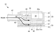
図2は熱媒体加熱装置10の斜視図、図3は熱媒体加熱装置10の正面図、図4は図3のIV-IV矢視による熱媒体加熱装置10の平面図であり、図5は図4のV-V線に沿う熱媒体加熱装置10の縦断面図である。なお、以下の説明では、図2中に示すX,Y,Z方向が、それぞれ熱媒体加熱装置10の「長手方向」、「短手方向」、「厚さ方向」と定義付けられている。
2 is a perspective view of the heat
図2〜図5、および図6〜図8にも示すように、この熱媒体加熱装置10は、例えば3つのボックス構成部材21,22,23が重ね合わせられて筐体状に構成された第1の熱媒体流通ボックス20と、2つのボックス構成部材51,52が重ね合わせられて筐体状に構成され、かつ第1の熱媒体流通ボックス20の下面に液密的に接合された第2の熱媒体流通ボックス50と、これら第1および第2の熱媒体流通ボックス20,50の間に挟装されたPTCヒータ40とを備えて構成されている。
As shown in FIGS. 2 to 5 and FIGS. 6 to 8, the heat
第1の熱媒体流通ボックス20は、平面視で長方形状の電子部品収容ボックス21の下面に、同じく長方形状を有する上部熱媒体流通ボックス22が液密的に接合され、電子部品収容ボックス21の上面に上部蓋部材23が液密的に被装された構成である。また、第2の熱媒体流通ボックス50は、上部熱媒体流通ボックス22と同じく長方形状を有する下部熱媒体流通ボックス51の下面に下部蓋部材52が液密的に被装された構成である。これらのボックス構成部材21,22,23,51,52は、アルミニウム合金等の熱伝導性材料により形成されている。
In the first heat
図2に示すように、上部蓋部材23は複数の固定ボルト25で電子部品収容ボックス21の上面に締結され、上部熱媒体流通ボックス22と下部熱媒体流通ボックス51と下部蓋部材52は複数の固定ボルト26で電子部品収容ボックス21の下面に締結されている。これにより、各ボックス構成部材21,22,23,51,52が一体化されている。各ボックス構成部材21,22,23,51,52の接合面には液状ガスケットが塗布されてシールされている。
As shown in FIG. 2, the
PTCヒータ40は、上部熱媒体流通ボックス22および下部熱媒体流通ボックス51よりも小さい長方形状かつ平板形状を有している。図5および図7に示すように、上部熱媒体流通ボックス22の下面に形成されたトレー状の凹部が下部熱媒体流通ボックス51の平坦な上面によって密閉されることでPTCヒータ収容室28が形成され、ここにPTCヒータ40が収容されている。PTCヒータ40の上面と下面は、それぞれ薄い熱伝達シートや熱伝達ペースト等を介して上部熱媒体流通ボックス22の下面と下部熱媒体流通ボックス51の上面とに熱伝達可能に密着している。
The
図5、図7、図8に示すように、電子部品収容ボックス21の内部は電子部品収容室30とされ、ここにPTCヒータ40を制御する制御基板(電子部品)31が格納設置される。制御基板31は、IGBT(Insulated Gate Bipolar Transistor:絶縁ゲート型バイポーラトランジスタ)や、FET(Field effect transistor:電界効果トランジスター)といった発熱性のある電子部品32や、他の電子部品33、および制御回路、電源回路等が組み込まれたものである。
As shown in FIGS. 5, 7, and 8, the inside of the electronic
電子部品収容ボックス21(電子部品収容室30)の底面は平坦な電子部品冷却壁部30aとなっている。図5に示すように、制御基板31は、図示しない固定構造によって電子部品冷却壁部30aよりも高い位置に固定され、発熱性のある電子部品32は制御基板31の下面側に配設され、図示しない絶縁層を介して電子部品冷却壁部30aに熱伝達可能に接触している。図2に示すように、電子部品収容ボックス21の一端面には配線導出部35が形成され、制御基板31から延出する配線部材36が、この配線導出部35から外部に導出される。
The bottom surface of the electronic component storage box 21 (electronic component storage chamber 30) is a flat electronic component cooling
図5、図7、図8に示すように、第1の熱媒体流通ボックス20を構成する電子部品収容ボックス21の下面に形成されたトレー状の凹部が上部熱媒体流通ボックス22の平坦な上面によって密閉されることで第1の熱媒体流通ボックス20の内部に第1の熱媒体流通路41が形成されている。上部熱媒体流通ボックス22の上面には、その長手方向に沿って複数の放熱フィン22aが形成されており(図6〜図8参照)、これらの放熱フィン22aによって第1の熱媒体流通路41が複数の平行する流路に区切られている。
As shown in FIG. 5, FIG. 7, and FIG. 8, the tray-shaped recess formed on the lower surface of the electronic
また、第2の熱媒体流通ボックス50を構成する下部熱媒体流通ボックス51の下面に形成されたトレー状の凹部が下部蓋部材52の平坦な上面によって密閉されることで第2の熱媒体流通ボックス50の内部に第2の熱媒体流通路42が形成されている。下部熱媒体流通ボックス51の下面には、その長手方向に沿って複数の放熱フィン51aが形成されており(図7、図8参照)、これらの放熱フィン51aによって第2の熱媒体流通路42が複数の平行する流路に区切られている。
In addition, the tray-shaped concave portion formed on the lower surface of the lower heat
上記のように、平坦な形状をしたPTCヒータ収容室28およびPTCヒータ40を挟むようにして、同じく平坦な形状をした第1の熱媒体流通路41と第2の熱媒体流通路42とが形成されている。そして、図5、図6、および図8に示すように、第1の熱媒体流通路41と第2の熱媒体流通路42の上流側端部同士および下流側端部同士をそれぞれ連通させるインレットヘッダ空間44およびアウトレットヘッダ空間45が形成されている。これらのヘッダ空間44,45は、図6中に二点鎖線で示すように、平面視で熱媒体加熱装置10の長手方向両端部に形成されており、それぞれ第1および第2の熱媒体流通路41,42の流路幅方向(短手方向)に沿い、且つ第1および第2の熱媒体流通路41,42の流路幅Wの全幅に亘って延在している。
As described above, the first heat
さらに、インレットヘッダ空間44とアウトレットヘッダ空間45とに、それぞれ熱媒体が循環する熱媒体循環回路11(図1参照)を接続可能にするインレット部47およびアウトレット部48が設けられている。これらのインレット部47およびアウトレット部48は、熱媒体循環回路11を構成するホース部材を接続可能なユニオンジョイント状であり、図2および図7、図8等に示すように、電子部品収容ボックス21に一体的に形成され、電子部品収容ボックス21の内部に形成された電子部品収容室30の厚さ(高さ)範囲と重なるように設けられている(図5、図7、図8参照)。
Further, the
また、図6に示すように、インレット部47およびアウトレット部48は、平面視で、それぞれの軸線方向47a,48aがインレットヘッダ空間44およびアウトレットヘッダ空間45の軸線方向44a,45aの略延長線上に位置するように配置されている。つまり、平面視で、インレット部47はインレットヘッダ空間44に直線的に繋がり、アウトレット部48はアウトレットヘッダ空間45に直線的に繋がっている。
Further, as shown in FIG. 6, in the
さらに、インレットヘッダ空間44の内面の、インレット部47寄りの位置、且つ第1および第2の熱媒体流通路41,42に対して離反する側に、第1および第2の熱媒体流通路41,42に向かって延びる突起部55が形成されている。この突起部55の高さは、例えばインレット部47の内径、あるいはインレットヘッダ空間44の通路幅の10〜40%程度に設定されている。
Further, the first and second heat
図8に示すように、側面視でインレット部47は、その軸線方向47aがインレットヘッダ空間44の上方を通過するように位置付けられている。インレット部47の内部奥側の通路内には斜面状の壁面である斜面部56が形成されており、インレット部47から流入した熱媒体は斜面部56に当たって下方に流れを変向され、インレットヘッダ空間44に流入するようになっている。
As shown in FIG. 8, the
図示しないが、アウトレット部48も同様に、その軸線方向がアウトレットヘッダ空間45の上方を通過するように位置付けられており、アウトレット部48の内部奥側の通路内に斜面部(非図示)が形成されている。熱媒体はアウトレットヘッダ空間45から上方に流れて斜面部に当たり、その流れの向きを変えられてアウトレット部48から流出する。
Although not shown, the
図4および図7、図8に示すように、インレットヘッダ空間44には流入温度検知センサ58が設けられ、アウトレットヘッダ空間45には流出温度検知センサ59が設けられている。これらのセンサ58,59は、それぞれビス60で前述の斜面部56の近傍に固定されている。流入温度検知センサ58はインレットヘッダ空間44を流れる熱媒体の流入温度を検知し、流出温度検知センサ59はアウトレットヘッダ空間45を流れる熱媒体の流出温度を検知するセンサである。
As shown in FIGS. 4, 7, and 8, the
以上のように構成された熱媒体加熱装置10において、図1に示す熱媒体循環回路11を流れる熱媒体は、図6および図8に示すように、熱媒体加熱装置10のインレット部47から流入してインレットヘッダ空間44に導かれる。その後、熱媒体は第1および第2の熱媒体流通路41,42に分流し、さらにそれぞれの熱媒体流通路41,42の放熱フィン22a,51aの間の流路に分流して同一方向(図5および図6中で右側から左側)に流れる。
In the heat
この時に熱媒体はPTCヒータ40と熱交換して加熱される。このように第1および第2の熱媒体流通路41,42を通過した熱媒体はアウトレットヘッダ空間45で合流し、アウトレット部48から流出して熱媒体加熱装置10の下流側に接続された放熱器6に流れ、加熱された熱媒体の熱が車室内の暖房に供される。
At this time, the heat medium exchanges heat with the
一方、電子部品収容ボックス21の電子部品収容室30に収容された制御基板31に搭載されて電子部品冷却壁部30aに接している発熱性のある電子部品32は、電子部品冷却壁部30aを介して第1の熱媒体流通路41を流れる熱媒体と熱交換することにより、その熱を冷却される。したがって、熱媒体は、PTCヒータ40によって加熱されると同時に、電子部品32の熱によっても加熱される。
On the other hand, the heat-generating
本構成の熱媒体加熱装置10によれば、熱媒体加熱装置10の内部に形成された第1および第2の熱媒体流通路41,42を、熱媒体が直線的且つ同一方向に流れ、Uターンする流れが存在しないため、熱媒体の圧力損失を低減させることができる。
According to the heat
インレットヘッダ空間44およびアウトレットヘッダ空間45は、それぞれ第1および第2の熱媒体流通路41,42の流路幅Wの方向に沿い、且つその流路幅Wの全幅に亘って延在している。このため、インレット部47からインレットヘッダ空間44に流入した熱媒体は、縮流や変向されることなく、速やかに第1の熱媒体流通路41と第2の熱媒体流通路42の全幅まで広がって流れる。また、第1の熱媒体流通路41と第2の熱媒体流通路42を流れ終わった熱媒体は、速やかにアウトレットヘッダ空間45に纏められてアウトレット部48から流出する。このため、熱媒体の圧力損失をより低減させることができる。
The
インレット部47およびアウトレット部48は、平面視(図6参照)でそれぞれの軸線方向47a,48aがインレットヘッダ空間44およびアウトレットヘッダ空間45の軸線方向44a,45aの略延長線上に位置するように配置されている。このため、インレット部47およびアウトレット部48が熱媒体加熱装置10の両端部から長手方向に向かって突出しない構成となっており、これによって熱媒体加熱装置10の長手方向のコンパクト化を図ることができる。
The
また、インレット部47から流入した熱媒体は、そのまま直線的にインレットヘッダ空間44の奥まで流れようとするが、インレットヘッダ空間44の内面に形成された突起部55により、インレット部47から流入した熱媒体の一部が流れの向きを変えられて第1および第2の熱媒体流通路41,42の比較的手前側の範囲に誘導される。このため、第1および第2の熱媒体流通路41,42の流路幅Wの全域に亘ってより均等に熱媒体を流し込むことができ、これによって熱媒体をPTCヒータ40と効率良く熱交換させて熱媒体加熱装置10の熱交換効率を高めることができる。
Further, the heat medium flowing in from the
さらに、この熱媒体加熱装置10では、第1の熱媒体流通ボックス20を構成する3つのボックス構成部材21,22,23のうち、内部に電子部品収容室30が設けられて厚み(高さ)寸法の最も大きな電子部品収容ボックス21にインレット部47とアウトレット部48とが設けられており、図5、図7、図8に示すように、インレット部47(アウトレット部48)が電子部品収容室30の厚さ(高さ)範囲に重なっている。
Furthermore, in this heat
本構成によれば、第1または第2の熱媒体流通ボックス20,50を構成する複数のボックス構成部材21,22,23,51,52のうち、最も厚さ(高さ)寸法の大きな電子部品収容ボックス21にインレット部47とアウトレット部48とが設けられる。このため、所定の太さのホース部材を接続可能にするべくインレット部47およびアウトレット部48にある程度の径を付与しても、これに起因して第1または第2の熱媒体流通ボックス20,50の厚さ寸法が大きくなることはない。これにより、熱媒体加熱装置10の厚さ(高さ)寸法のコンパクト化を図ることができる。
According to this configuration, the electron having the largest thickness (height) dimension among the plurality of
また、この熱媒体加熱装置10は、インレットヘッダ空間44を流れる熱媒体の流入温度を検知する流入温度検知センサ58と、アウトレットヘッダ空間45を流れる熱媒体の流出温度を検知する流出温度検知センサ59を備えている。即ち、電子部品収容室30の近傍に配置されたインレットヘッダ空間44およびアウトレットヘッダ空間45に流入温度検知センサ58および流出温度検知センサ59が設けられている。このため、これらの温度検知センサ58,59による温度検知精度を高めるとともに、これらの温度検知センサ58,59を電子部品収容室30に他の電子部品と一緒に収容することができ、電子部品類を1つに纏めることによって熱媒体加熱装置のコンパクト化を図ることができる。
The heat
流入温度検知センサ58および流出温度検知センサ59は、熱媒体の流れが当たる斜面部56の近傍に設けられている。即ち、熱媒体の流れが澱みなく当たることによって該熱媒体の温度が良好に伝達なされる部位にこれらの温度検知センサ58,59が設けられるため、熱媒体の温度検知精度を高めることができる。熱媒体の流れが当たる斜面部56は斜面状であるため、熱媒体の流れに大きな抵抗が付与されることはない。
The inflow
以上説明したように、本実施形態に係る熱媒体加熱装置10、およびこれを用いた車両用空調装置1によれば、熱媒体加熱装置10の内部における熱媒体の圧力損失を低減させるとともに、熱交換効率を高め、併せて熱媒体加熱装置10のコンパクト化を図ることができる。
As described above, according to the heat
なお、本発明は上記実施形態の構成のみに限定されるものではなく、適宜変更や改良を加えることができ、このように変更や改良を加えた実施形態も本発明の権利範囲に含まれるものとする。
例えば、本発明に係る熱媒体加熱装置10の内部形状やレイアウト等は、特許請求の範囲を逸脱しない範囲であれば変更してもよい。
また、本発明に係る車両用空調装置1の構成は、必ずしも図1に記載された構成の通りである必要はなく、その構成部品やレイアウトは適宜変更することができる。
Note that the present invention is not limited to the configurations of the above-described embodiments, and modifications and improvements can be appropriately added. Embodiments with such modifications and improvements are also included in the scope of rights of the present invention. And
For example, the internal shape and layout of the heat
Further, the configuration of the
1 車両用空調装置
4 ブロア
5 冷却器
6 放熱器
10 熱媒体加熱装置
11 熱媒体循環回路
20 第1の熱媒体流通ボックス
21 電子部品収容ボックス
31 制御基板(電子部品)
32 電子部品
33 電子部品
40 PTCヒータ
41 第1の熱媒体流通路
42 第2の熱媒体流通路
44 インレットヘッダ空間
45 アウトレットヘッダ空間
47 インレット部
48 アウトレット部
50 第2の熱媒体流通ボックス
55 突起部
56 斜面部(斜面状の壁面)
58 流入温度検知センサ
59 流出温度検知センサ
W 熱媒体流通路の流路幅
1
32
58 Inflow
Claims (6)
前記PTCヒータの一面側に密着して内部に第1の熱媒体流通路が形成された第1の熱媒体流通ボックスと、
前記PTCヒータの他面側に密着して内部に第2の熱媒体流通路が形成され、且つ前記第1の熱媒体流通ボックスに接合される第2の熱媒体流通ボックスと、
前記第1および第2の熱媒体流通路の上流側端部同士および下流側端部同士をそれぞれ連通させるインレットヘッダ空間およびアウトレットヘッダ空間と、
前記インレットヘッダ空間に熱媒体を流入させるインレット部と、
前記アウトレットヘッダ空間から前記熱媒体を流出させるアウトレット部と、
前記インレットヘッダ空間の内面の、前記インレット部寄りの位置に形成され、前記インレット部からの前記熱媒体の流入方向と交わる向きに延びる突起部と、
を備え、
前記インレット部および前記アウトレット部は、平面視でそれぞれの軸線方向が前記インレットヘッダ空間および前記アウトレットヘッダ空間の軸線方向の略延長線上に位置するように配置されるとともに、
前記突起部は、前記インレットヘッダ空間の内面における前記第1および第2の熱媒体流通路に対して離反する側に形成されている熱媒体加熱装置。 A PTC heater,
A first heat medium flow box in which a first heat medium flow passage is formed in close contact with one surface side of the PTC heater;
A second heat medium flow box in which a second heat medium flow passage is formed in close contact with the other surface side of the PTC heater and which is joined to the first heat medium flow box;
An inlet header space and an outlet header space that respectively connect the upstream end portions and the downstream end portions of the first and second heat medium flow passages,
An inlet portion for allowing a heat medium to flow into the inlet header space,
An outlet part for causing the heat medium to flow out from the outlet header space,
An inner surface of the inlet header space, a projection portion formed at a position closer to the inlet portion, and extending in a direction intersecting with an inflow direction of the heat medium from the inlet portion,
Equipped with
The inlet part and the outlet part are arranged such that their respective axial directions in a plan view are located on a substantially extended line in the axial direction of the inlet header space and the outlet header space,
The heating medium heating device , wherein the protrusion is formed on a side of the inner surface of the inlet header space that is separated from the first and second heating medium flow passages .
前記インレット部および前記アウトレット部は、前記電子部品収容ボックス部材に設けられている請求項1または2に記載の熱媒体加熱装置。 One of the first heat medium distribution box and the second heat medium distribution box includes an electronic component housing box member that houses an electronic component for controlling the PTC heater,
The heat medium heating device according to claim 1, wherein the inlet section and the outlet section are provided in the electronic component housing box member.
前記放熱器に、請求項1から5のいずれかに記載の熱媒体加熱装置により加熱された前記熱媒体が循環可能に構成された車両用空調装置。 A blower that circulates outside air or air inside the vehicle, a cooler that is provided on the downstream side of the blower, and a radiator that is provided on the downstream side of the cooler,
An air conditioner for a vehicle, wherein the heat medium heated by the heat medium heating device according to any one of claims 1 to 5 can be circulated in the radiator.
Priority Applications (5)
| Application Number | Priority Date | Filing Date | Title |
|---|---|---|---|
| JP2016116317A JP6698434B2 (en) | 2016-06-10 | 2016-06-10 | Heat medium heating device and vehicle air conditioner using the same |
| US16/087,482 US20190135078A1 (en) | 2016-06-10 | 2016-10-21 | Heating medium heating device and vehicle air conditioner using same |
| CN201680084057.1A CN109311368A (en) | 2016-06-10 | 2016-10-21 | Thermal medium heating device and the air conditioner for vehicles for using it |
| DE112016006954.5T DE112016006954T5 (en) | 2016-06-10 | 2016-10-21 | Heating medium heater and vehicle air conditioner using these |
| PCT/JP2016/081340 WO2017212665A1 (en) | 2016-06-10 | 2016-10-21 | Heating medium heating device and vehicle air conditioner using same |
Applications Claiming Priority (1)
| Application Number | Priority Date | Filing Date | Title |
|---|---|---|---|
| JP2016116317A JP6698434B2 (en) | 2016-06-10 | 2016-06-10 | Heat medium heating device and vehicle air conditioner using the same |
Publications (3)
| Publication Number | Publication Date |
|---|---|
| JP2017218117A JP2017218117A (en) | 2017-12-14 |
| JP2017218117A5 JP2017218117A5 (en) | 2019-05-23 |
| JP6698434B2 true JP6698434B2 (en) | 2020-05-27 |
Family
ID=60577684
Family Applications (1)
| Application Number | Title | Priority Date | Filing Date |
|---|---|---|---|
| JP2016116317A Expired - Fee Related JP6698434B2 (en) | 2016-06-10 | 2016-06-10 | Heat medium heating device and vehicle air conditioner using the same |
Country Status (5)
| Country | Link |
|---|---|
| US (1) | US20190135078A1 (en) |
| JP (1) | JP6698434B2 (en) |
| CN (1) | CN109311368A (en) |
| DE (1) | DE112016006954T5 (en) |
| WO (1) | WO2017212665A1 (en) |
Families Citing this family (2)
| Publication number | Priority date | Publication date | Assignee | Title |
|---|---|---|---|---|
| EP3722124B1 (en) * | 2019-04-08 | 2023-12-13 | Borgwarner Emissions Systems Spain, S.L.U. | Heating device for use thereof in a vehicle |
| CN112895846B (en) * | 2021-02-02 | 2022-04-26 | 镇江海姆霍兹传热传动系统有限公司 | Electric vehicle, electric heater and electric heating cavity assembly thereof |
Family Cites Families (10)
| Publication number | Priority date | Publication date | Assignee | Title |
|---|---|---|---|---|
| JPS5535740B2 (en) | 1972-04-25 | 1980-09-16 | ||
| JPS5535742B2 (en) | 1972-09-30 | 1980-09-16 | ||
| KR101082474B1 (en) * | 2004-12-28 | 2011-11-11 | 한라공조주식회사 | Heat exchanger |
| US20080023185A1 (en) * | 2006-07-25 | 2008-01-31 | Henry Earl Beamer | Heat exchanger assembly |
| JP4981386B2 (en) | 2006-08-30 | 2012-07-18 | 三菱重工業株式会社 | Heat medium heating device and vehicle air conditioner using the same |
| JP2011152907A (en) * | 2010-01-28 | 2011-08-11 | Mitsubishi Heavy Ind Ltd | Electric heating system and vehicular air conditioner |
| JP2012131433A (en) * | 2010-12-22 | 2012-07-12 | Mitsubishi Heavy Ind Ltd | Heater for heat medium |
| JP2013056641A (en) * | 2011-09-09 | 2013-03-28 | Mitsubishi Heavy Ind Ltd | Heating medium heating device and vehicular air-conditioner having the same |
| JP2013180690A (en) * | 2012-03-02 | 2013-09-12 | Mitsubishi Heavy Ind Ltd | Heat medium heating device and vehicle air conditioner including the same |
| JP2014129090A (en) * | 2014-02-10 | 2014-07-10 | Mitsubishi Heavy Ind Ltd | Heat medium heating device and vehicle air conditioner using the same |
-
2016
- 2016-06-10 JP JP2016116317A patent/JP6698434B2/en not_active Expired - Fee Related
- 2016-10-21 WO PCT/JP2016/081340 patent/WO2017212665A1/en active Application Filing
- 2016-10-21 DE DE112016006954.5T patent/DE112016006954T5/en not_active Withdrawn
- 2016-10-21 CN CN201680084057.1A patent/CN109311368A/en active Pending
- 2016-10-21 US US16/087,482 patent/US20190135078A1/en not_active Abandoned
Also Published As
| Publication number | Publication date |
|---|---|
| US20190135078A1 (en) | 2019-05-09 |
| WO2017212665A1 (en) | 2017-12-14 |
| DE112016006954T5 (en) | 2019-02-21 |
| CN109311368A (en) | 2019-02-05 |
| JP2017218117A (en) | 2017-12-14 |
Similar Documents
| Publication | Publication Date | Title |
|---|---|---|
| JP5535742B2 (en) | Heat medium heating device and vehicle air conditioner using the same | |
| JP5979892B2 (en) | Heat medium heating device and vehicle air conditioner equipped with the same | |
| JP5024600B2 (en) | Heating element cooling structure and driving device having the structure | |
| JP5535740B2 (en) | Heat medium heating device and vehicle air conditioner using the same | |
| WO2013157357A1 (en) | Heating medium heating apparatus, and vehicle air conditioner provided with same | |
| US7977606B2 (en) | Heat-transer-medium heating apparatus and vehicular air-conditioning apparatus using the same | |
| JP6675937B2 (en) | Heat medium heating device and vehicle air conditioner using the same | |
| WO2013047090A1 (en) | Heat medium-heating device and vehicle air-conditioning device with same | |
| US20120237192A1 (en) | Heat medium heating apparatus and vehicular air-conditioning system including the same | |
| US9186956B2 (en) | Heat medium heating unit and vehicle air conditioning apparatus provided with the same | |
| WO2013035475A1 (en) | Heat medium heating device and vehicle air-conditioning device with same | |
| JP2014129090A (en) | Heat medium heating device and vehicle air conditioner using the same | |
| JP5951205B2 (en) | Heat medium heating device and vehicle air conditioner equipped with the same | |
| JP6698434B2 (en) | Heat medium heating device and vehicle air conditioner using the same | |
| JP2012017031A (en) | Heat medium-heating device and air conditioner for vehicle using the same | |
| JP2013177028A (en) | Heating medium heating system | |
| JP2013060098A (en) | Heat medium heating device and vehicular air conditioner including the same | |
| JP2017211093A (en) | Fluid heating device |
Legal Events
| Date | Code | Title | Description |
|---|---|---|---|
| A711 | Notification of change in applicant |
Free format text: JAPANESE INTERMEDIATE CODE: A712 Effective date: 20180613 |
|
| A521 | Request for written amendment filed |
Free format text: JAPANESE INTERMEDIATE CODE: A523 Effective date: 20190409 |
|
| A621 | Written request for application examination |
Free format text: JAPANESE INTERMEDIATE CODE: A621 Effective date: 20190409 |
|
| TRDD | Decision of grant or rejection written | ||
| A01 | Written decision to grant a patent or to grant a registration (utility model) |
Free format text: JAPANESE INTERMEDIATE CODE: A01 Effective date: 20200331 |
|
| A61 | First payment of annual fees (during grant procedure) |
Free format text: JAPANESE INTERMEDIATE CODE: A61 Effective date: 20200428 |
|
| R150 | Certificate of patent or registration of utility model |
Ref document number: 6698434 Country of ref document: JP Free format text: JAPANESE INTERMEDIATE CODE: R150 |
|
| LAPS | Cancellation because of no payment of annual fees |