WO2017002608A1 - 燃料電池 - Google Patents
燃料電池 Download PDFInfo
- Publication number
- WO2017002608A1 WO2017002608A1 PCT/JP2016/067699 JP2016067699W WO2017002608A1 WO 2017002608 A1 WO2017002608 A1 WO 2017002608A1 JP 2016067699 W JP2016067699 W JP 2016067699W WO 2017002608 A1 WO2017002608 A1 WO 2017002608A1
- Authority
- WO
- WIPO (PCT)
- Prior art keywords
- region
- air electrode
- phase
- fuel cell
- oxidant gas
- Prior art date
- Legal status (The legal status is an assumption and is not a legal conclusion. Google has not performed a legal analysis and makes no representation as to the accuracy of the status listed.)
- Ceased
Links
Images


Classifications
-
- H—ELECTRICITY
- H01—ELECTRIC ELEMENTS
- H01M—PROCESSES OR MEANS, e.g. BATTERIES, FOR THE DIRECT CONVERSION OF CHEMICAL ENERGY INTO ELECTRICAL ENERGY
- H01M4/00—Electrodes
- H01M4/86—Inert electrodes with catalytic activity, e.g. for fuel cells
- H01M4/90—Selection of catalytic material
- H01M4/9016—Oxides, hydroxides or oxygenated metallic salts
- H01M4/9025—Oxides specially used in fuel cell operating at high temperature, e.g. SOFC
- H01M4/9033—Complex oxides, optionally doped, of the type M1MeO3, M1 being an alkaline earth metal or a rare earth, Me being a metal, e.g. perovskites
-
- H—ELECTRICITY
- H01—ELECTRIC ELEMENTS
- H01M—PROCESSES OR MEANS, e.g. BATTERIES, FOR THE DIRECT CONVERSION OF CHEMICAL ENERGY INTO ELECTRICAL ENERGY
- H01M4/00—Electrodes
- H01M4/86—Inert electrodes with catalytic activity, e.g. for fuel cells
- H01M4/8636—Inert electrodes with catalytic activity, e.g. for fuel cells with a gradient in another property than porosity
- H01M4/8642—Gradient in composition
-
- H—ELECTRICITY
- H01—ELECTRIC ELEMENTS
- H01M—PROCESSES OR MEANS, e.g. BATTERIES, FOR THE DIRECT CONVERSION OF CHEMICAL ENERGY INTO ELECTRICAL ENERGY
- H01M8/00—Fuel cells; Manufacture thereof
- H01M8/10—Fuel cells with solid electrolytes
-
- H—ELECTRICITY
- H01—ELECTRIC ELEMENTS
- H01M—PROCESSES OR MEANS, e.g. BATTERIES, FOR THE DIRECT CONVERSION OF CHEMICAL ENERGY INTO ELECTRICAL ENERGY
- H01M8/00—Fuel cells; Manufacture thereof
- H01M8/10—Fuel cells with solid electrolytes
- H01M8/12—Fuel cells with solid electrolytes operating at high temperature, e.g. with stabilised ZrO2 electrolyte
- H01M8/124—Fuel cells with solid electrolytes operating at high temperature, e.g. with stabilised ZrO2 electrolyte characterised by the process of manufacturing or by the material of the electrolyte
- H01M8/1246—Fuel cells with solid electrolytes operating at high temperature, e.g. with stabilised ZrO2 electrolyte characterised by the process of manufacturing or by the material of the electrolyte the electrolyte consisting of oxides
- H01M8/1253—Fuel cells with solid electrolytes operating at high temperature, e.g. with stabilised ZrO2 electrolyte characterised by the process of manufacturing or by the material of the electrolyte the electrolyte consisting of oxides the electrolyte containing zirconium oxide
-
- H—ELECTRICITY
- H01—ELECTRIC ELEMENTS
- H01M—PROCESSES OR MEANS, e.g. BATTERIES, FOR THE DIRECT CONVERSION OF CHEMICAL ENERGY INTO ELECTRICAL ENERGY
- H01M4/00—Electrodes
- H01M4/86—Inert electrodes with catalytic activity, e.g. for fuel cells
- H01M2004/8678—Inert electrodes with catalytic activity, e.g. for fuel cells characterised by the polarity
- H01M2004/8689—Positive electrodes
-
- Y—GENERAL TAGGING OF NEW TECHNOLOGICAL DEVELOPMENTS; GENERAL TAGGING OF CROSS-SECTIONAL TECHNOLOGIES SPANNING OVER SEVERAL SECTIONS OF THE IPC; TECHNICAL SUBJECTS COVERED BY FORMER USPC CROSS-REFERENCE ART COLLECTIONS [XRACs] AND DIGESTS
- Y02—TECHNOLOGIES OR APPLICATIONS FOR MITIGATION OR ADAPTATION AGAINST CLIMATE CHANGE
- Y02E—REDUCTION OF GREENHOUSE GAS [GHG] EMISSIONS, RELATED TO ENERGY GENERATION, TRANSMISSION OR DISTRIBUTION
- Y02E60/00—Enabling technologies; Technologies with a potential or indirect contribution to GHG emissions mitigation
- Y02E60/30—Hydrogen technology
- Y02E60/50—Fuel cells
-
- Y—GENERAL TAGGING OF NEW TECHNOLOGICAL DEVELOPMENTS; GENERAL TAGGING OF CROSS-SECTIONAL TECHNOLOGIES SPANNING OVER SEVERAL SECTIONS OF THE IPC; TECHNICAL SUBJECTS COVERED BY FORMER USPC CROSS-REFERENCE ART COLLECTIONS [XRACs] AND DIGESTS
- Y02—TECHNOLOGIES OR APPLICATIONS FOR MITIGATION OR ADAPTATION AGAINST CLIMATE CHANGE
- Y02P—CLIMATE CHANGE MITIGATION TECHNOLOGIES IN THE PRODUCTION OR PROCESSING OF GOODS
- Y02P70/00—Climate change mitigation technologies in the production process for final industrial or consumer products
- Y02P70/50—Manufacturing or production processes characterised by the final manufactured product
Definitions
- the present invention relates to a fuel cell and a fuel cell device.
- a fuel cell including a fuel electrode, an air electrode, and a solid electrolyte layer disposed between the fuel electrode and the air electrode is known (see, for example, Patent Document 1).
- fuel gas for example, hydrogen gas
- oxidant gas for example, air
- the air electrode is made of a porous material.
- the output of the fuel cell may decrease as power generation is repeated.
- the present inventors have newly found that one of the causes of the decrease in output is a change in the fine structure of the air electrode, and this fine structure change is likely to occur in a region of the air electrode where the current density is large.
- the present invention is based on such new knowledge and aims to provide a fuel cell and a fuel cell device capable of improving the durability of the air electrode.
- the fuel cell according to the present invention includes a fuel electrode, an air electrode to which an oxidant gas is supplied, and a solid electrolyte layer disposed between the fuel electrode and the air electrode.
- the air electrode contains a perovskite oxide as a main component and a compound containing at least one of S and Cr as a subcomponent.
- the surface of the air electrode opposite to the solid electrolyte layer has a first region and a second region located downstream of the first region in the oxidant gas flow direction in which the oxidant gas flows on the surface.
- Each of the first region and the second region includes a main phase composed of a perovskite oxide and a second phase composed of a compound containing at least one of S and Cr.
- the area occupation ratio of the second phase in the first region is larger than the area occupation ratio of the second phase in the second region.
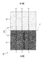
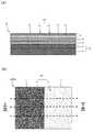
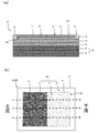
- Sectional drawing which shows the structure of the fuel cell which concerns on embodiment It is a top view of the air electrode which concerns on embodiment. Sectional drawing and top view which show the structure of the air electrode which concerns on other embodiment. Sectional drawing and top view which show the structure of the air electrode which concerns on other embodiment. Sectional drawing and top view which show the structure of the air electrode which concerns on other embodiment.
- the fuel cell device 1 includes a container 2 and a fuel cell 10 accommodated in the container 2.
- Container 2 The interior of the container 2 is separated into an air electrode side space 3 and a fuel electrode side space 4.
- the air electrode side space 3 and the fuel electrode side space 4 can be partitioned by, for example, a known metal separator or a gas seal film.
- the air electrode side space 3 is provided with an oxidant gas inlet 5 and an oxidant gas outlet 6.
- the oxidant gas for example, air
- the oxidant gas introduced from the oxidant gas inlet 5 into the air electrode side space 3 is supplied to the air electrode 50 of the fuel cell 10.
- the oxidant gas flows on the surface 50S of the air electrode 50 in a predetermined direction.
- the oxidant gas that has passed over the surface 50S of the air electrode 50 is led out from the oxidant gas outlet 6 to the outside.
- oxidant gas flow direction 50D The direction in which the oxidant gas flows on the surface 50S of the air electrode 50 depends on the mutual positional relationship between the oxidant gas inlet 5 and the oxidant gas flow inlet 6. Can be adjusted.
- the oxidant gas normally flows from the oxidant gas inlet 5 side toward the oxidant gas outlet 6 side, but is not limited thereto.
- the fuel electrode side space 4 is provided with a fuel gas inlet 7 and a fuel gas outlet 8.
- the fuel gas for example, hydrogen gas
- the fuel gas that has passed over the surface of the fuel electrode 20 is led out from the fuel gas outlet 8.
- the configuration of the fuel cell 10 will be described with reference to the drawings.
- the fuel cell 10 is a so-called SOFC (Solid Oxide Fuel Cell).
- SOFC Solid Oxide Fuel Cell
- the fuel cell 10 can take various forms such as a vertical stripe type, a horizontal stripe type, a flat plate type, a fuel electrode support type, or a cylindrical type.
- FIG. 1 is a cross-sectional view showing the configuration of the fuel cell 10.
- the fuel cell 10 includes a fuel electrode 20, a solid electrolyte layer 30, a barrier layer 40, and an air electrode 50.
- the fuel electrode 20 functions as an anode of the fuel cell 10. During operation of the fuel cell 10, fuel gas is supplied to the surface 20 ⁇ / b> S of the fuel electrode 20.
- the fuel electrode 20 may have a fuel electrode current collecting layer 21 and a fuel electrode active layer 22 as shown in FIG.
- the anode current collecting layer 21 is a porous body excellent in gas permeability.
- materials conventionally used for SOFC anode current collecting layers can be used.
- NiO nickel oxide
- -8YSZ 8 mol% yttria is stabilized).
- Zirconia and NiO—Y 2 O 3 (yttria).
- NiO nickel oxide
- Y 2 O 3 yttria
- the thickness of the anode current collecting layer 21 can be set to 0.1 mm to 5.0 mm, for example.
- the anode active layer 22 is disposed on the anode current collecting layer 21.
- the anode active layer 22 is a denser porous body than the anode current collecting layer 21.
- materials conventionally used for the anode active layer of SOFC can be used, for example, NiO-8YSZ.
- NiO-8YSZ materials conventionally used for the anode active layer of SOFC
- the thickness of the anode active layer 22 can be set to, for example, 5.0 ⁇ m to 30 ⁇ m.
- the solid electrolyte layer 30 is disposed between the fuel electrode 20 and the air electrode 50. In the present embodiment, the solid electrolyte layer 30 is sandwiched between the fuel electrode 20 and the barrier layer 40. The solid electrolyte layer 30 has a function of transmitting oxygen ions generated at the air electrode 50. The solid electrolyte layer 30 is denser than the fuel electrode 20 and the air electrode 50.
- the solid electrolyte layer 30 may contain ZrO 2 (zirconia) as a main component.
- the solid electrolyte layer 30 may contain additives such as Y 2 O 3 (yttria) and / or Sc 2 O 3 (scandium oxide) in addition to zirconia. These additives function as stabilizers.
- the molar composition ratio of the stabilizer to zirconia can be about 3:97 to 20:80. Therefore, examples of the material of the solid electrolyte layer 30 include 3YSZ, 8YSZ, 10YSZ, or ScSZ (scandia-stabilized zirconia).
- the thickness of the solid electrolyte layer 30 can be set to 3 ⁇ m to 30 ⁇ m, for example.
- the composition X contains the substance Y as a main component means that the substance Y accounts for 70% by weight or more in the entire composition X, and is 90% by weight or more. More preferred.
- the barrier layer 40 is disposed between the solid electrolyte layer 30 and the air electrode 50.
- the barrier layer 40 suppresses the formation of a high resistance layer between the solid electrolyte layer 30 and the air electrode 50.
- the barrier layer 40 is denser than the fuel electrode 20 and the air electrode 50.
- the barrier layer 40 can contain a ceria-based material such as GDC (gadolinium doped ceria) or SDC (samarium doped ceria) as a main component.
- the thickness of the barrier layer 40 can be set to 3 ⁇ m to 20 ⁇ m, for example.
- the air electrode 50 is disposed on the barrier layer 40.
- the air electrode 50 functions as a cathode of the fuel cell 10.
- the air electrode 50 is a porous body.
- the thickness of the air electrode 50 can be, for example, 10 ⁇ m to 300 ⁇ m.
- the air electrode 50 has a surface 50 ⁇ / b> S provided on the opposite side of the solid electrolyte layer 30.
- an oxidant gas is supplied to the air electrode 50. As shown in FIG. 1, the oxidant gas flows on the surface 50S of the air electrode 50 along the oxidant gas flow direction 50D.
- the air electrode 50 contains a perovskite complex oxide represented by the general formula ABO 3 as a main component.
- perovskite complex oxides include LSCF ((La, Sr) (Co, Fe) O 3 : lanthanum strontium cobalt ferrite), LSF ((La, Sr) FeO 3 : lanthanum strontium ferrite), LSC (( La, Sr) CoO 3 : lanthanum strontium cobaltite), LNF (La (Ni, Fe) O 3 : lanthanum nickel ferrite), LSM ((La, Sr) MnO 3 : lanthanum strontium manganate), etc. It is not limited to this.
- Such a perovskite complex oxide has conductivity.
- the air electrode 50 contains a compound containing at least one of S and Cr (hereinafter abbreviated as “compound” as appropriate) as a subcomponent.
- a compound containing at least one of S and Cr hereinafter abbreviated as “compound” as appropriate
- a sulfate or a composite oxide is preferable.
- the sulfate include strontium sulfate (for example, SrSO 4 ).
- the composite oxide include strontium chromate (for example, SrCrO 4 ).
- Such a subcomponent compound has lower conductivity than the main component perovskite complex oxide. That is, the conductivity of the subcomponent compound is lower than the conductivity of the perovskite complex oxide as the main component.
- the subcomponent compound may be insulating.
- the composition X containing the substance Z as an accessory component means that the substance Z occupies 30% by weight or less in the entire composition X and is 10% by weight or less. More preferred.
- the air electrode 50 includes (Co, Fe) 3 O 4 (including Co 2 FeO 4 , Co 1.5 Fe 1.5 O 4, CoFe 2 O 4, etc.) in addition to a compound containing at least one of S and Cr.
- Co 3 O 4 tricobalt tetroxide
- CoO cobalt oxide
- the air electrode 50 includes (Co, Fe) 3 O 4 (including Co 2 FeO 4 , Co 1.5 Fe 1.5 O 4, CoFe 2 O 4, etc.) in addition to a compound containing at least one of S and Cr.
- Co 3 O 4 tricobalt tetroxide
- CoO cobalt oxide
- the air electrode 50 has a first portion 51 and a second portion 52.
- the first portion 51 is located upstream of the second portion 52 in the oxidant gas flow direction 50D.
- the second portion 52 is located downstream of the first portion 51 in the oxidant gas flow direction 50D.
- the first portion 51 and the second portion 52 differ in the composition ratio between the main component perovskite complex oxide and the subcomponent compound.
- the content ratio of the main component perovskite complex oxide in the first portion 51 is smaller than the content ratio of the main component perovskite complex oxide in the second portion 52.
- the perovskite complex oxide contained in the first portion 51 as a main component may be different from the perovskite complex oxide contained in the second portion 52 as a main component, but is preferably the same type.
- the content ratio of the subcomponent compound in the first portion 51 is larger than the content ratio of the subcomponent compound in the second portion 52.
- the compound contained in the first portion 51 as an accessory component may be different from the compound contained in the second portion 52 as an accessory component, but is preferably the same type.
- FIG. 2 is a plan view of the surface 50 ⁇ / b> S of the air electrode 50.
- the surface 50S of the air electrode 50 has a first region S1 and a second region S2.
- region S1 is the surface of the 1st part 51 among the air electrodes 50.
- FIG. The first region S1 is located upstream of the second region S2 in the oxidant gas flow direction 50D.
- the first region S1 is a region upstream of the center line CL of the surface 50S in the oxidant gas flow direction 50D in the surface 50S.
- the first region S1 only needs to be positioned upstream of the second region S2, and the shape, size, and position of the first region S1 are not particularly limited.
- the area ratio of the first region S1 in the surface 50S is not particularly limited, but can be 10% or more and 50% or less, and preferably 15% or more and 40% or less.
- region S1 contains the main phase comprised by the perovskite type complex oxide which is a main component, and the 2nd phase comprised by the compound which is a subcomponent.
- the second region S2 is the surface of the second portion 52 of the air electrode 50.
- the second region S2 is located downstream of the first region S1 in the oxidant gas flow direction 50D.
- the second region S2 is a region on the downstream side of the center line CL in the oxidizing gas flow direction 50D in the surface 50S.
- the second region S2 only needs to be positioned downstream of the first region S1, and the shape, size, and position of the second region S2 are not particularly limited.
- the area ratio of the second region S2 in the surface 50S is not particularly limited, but can be 10% or more and 50% or less, and preferably 15% or more and 40% or less.
- region S2 contains the main phase comprised by the perovskite type complex oxide which is a main component.
- region S2 does not need to contain the 2nd phase comprised with the compound which is a subcomponent.
- the concentration of the oxidant gas tends to be higher than that in the second region S2 on the downstream side, so that the current density tends to increase. Therefore, in the present embodiment, the area occupancy of the second phase in the first region S1 is larger than the area occupancy of the second phase in the second region S2.
- the area occupancy of the second phase in the first region S1 can be 1% or more and 20% or less, and is preferably 3% or more and 15% or less.
- the area occupation ratio of the main phase in the first region S1 can be 80% or more, and preferably 85% or more. A method for calculating the area occupancy will be described later.
- the area occupancy of the second phase in the second region S2 can be 0% or more and 5% or less, and is preferably 0.5% or more and 2.5% or less.
- the area occupancy of the main phase in the second region S2 can be 95% or more, and is preferably 97% or more.
- the surface 50S of the air electrode 50 is subjected to precision mechanical polishing.
- ion milling processing is performed on the surface 50S of the air electrode 50 using IM4000 of Hitachi High-Technologies Corporation.
- a backscattered electron image of the first region S1 magnified at a magnification of 10,000 times is acquired by a FE-SEM (Field Emission Scanning Electron Microscope) using a backscattered electron detector.
- a FE-SEM Field Emission Scanning Electron Microscope
- a backscattered electron detector for example, an FE-SEM (model: ULTRA55) manufactured by Zeiss (Germany) set to an acceleration voltage of 1 kV and a working distance of 2 mm can be used.
- the main phase perovskite complex oxide
- the second phase compound containing at least one of S and Cr
- the gas phase pores
- the main phase is displayed as “gray white”, the second phase as “gray”, and the gas phase as “black”.
- Such ternarization by contrast is realized by classifying the luminance of an image into 256 gradations.
- the method for discriminating the main phase, the second phase, and the gas phase is not limited to the method using the light / dark difference in the reflected electron image.
- SEM-EDS Sccanning Electron Microscope Energy Dispersive X-ray Spectrometry
- the composition of each particle in the image is identified by comparing with the reflected electron image.
- the second phase and the gas phase can be ternarized with high accuracy.
- the second phase on the reflected electron image is identified by image analysis of the reflected electron image in which the main phase, the second phase, and the gas phase are ternarized by the image analysis software HALCON manufactured by MVTec (Germany). To do.
- the ratio of the total area of the second phase to the total area of the solid phase (main phase and second phase) excluding the pores in the analysis image is calculated.
- the ratio of the total area of the second phase calculated in this way is the area occupation ratio of the second phase in the first region S1.
- the total area of the second phase relative to the total area of the solid phase (main phase and second phase only) excluding the gas phase and the third phase in the analysis image It is sufficient to calculate the ratio of.
- the area occupancy of the second phase in the second region S2 and the area occupancy of the main phase in each of the first region S1 and the second region S2 can be calculated.
- a molded body of the anode current collecting layer 21 is formed by molding the anode current collecting layer material powder by a die press molding method.
- a fuel electrode active layer slurry is prepared by adding PVA (polyvinyl alcohol) as a binder to a mixture of the fuel electrode active layer material powder and a pore-forming agent (for example, PMMA).
- PVA polyvinyl alcohol
- a pore-forming agent for example, PMMA
- the solid electrolyte layer 30 molded body is formed by applying the solid electrolyte layer slurry on the molded body of the fuel electrode active layer 22 by a printing method or the like.
- terpineol and a binder are mixed with the barrier layer material powder to prepare a barrier layer slurry.
- the molded object of the barrier layer 40 is formed by apply
- the fuel electrode 20, the solid electrolyte layer 30, and the barrier layer 40 are fired (1350 ° C. to 1450 ° C., 1 hour to 20 hours) to form the fuel electrode 20, the solid electrolyte layer 30, and the barrier layer 40. Form.
- the perovskite type complex oxide material for air electrode (main component), the compound material (subcomponent) containing at least one of S and Cr, water and binder are mixed for 24 hours with a ball mill for the first part.
- a ball mill for the first part.
- the content rate of the compound material in the slurry for 1st parts is set higher than the content rate of the compound material in the slurry for 2nd parts mentioned later.
- the first portion 51 of the air electrode 50 is formed by applying the first portion slurry to the half surface of the barrier layer surface.
- a second portion slurry is prepared by mixing a perovskite-type composite oxide material (main component) for air electrode, water, and a binder with a ball mill for 24 hours.
- a compound material containing at least one of S and Cr may be added, but the content of the compound material in the second partial slurry is set lower than the content of the compound material in the first partial slurry. .
- the second portion 52 of the air electrode 50 is formed by applying the second portion slurry to the remaining half of the barrier layer surface.
- a molded body of the air electrode 50 is completed.
- the air electrode 50 is formed by firing the molded body of the air electrode 50 (1000 to 1100 ° C., 1 to 10 hours).
- the air electrode 50 has the first portion 51 and the second portion 52.
- the first portion 51 and A base portion 53 that supports the second portion 52 may be provided.
- the base portion 53 contains a perovskite complex oxide represented by the general formula ABO 3 as a main component.
- the base portion 53 may not contain a compound containing at least one of S and Cr.
- the thickness of the first portion 51 and the second portion 52 is not particularly limited, but can be 1% or more and 30% or less of the thickness of the air electrode 50, and is preferably 5% or more and 20% or less.
- the air electrode 50 having the base portion 53 can be manufactured as follows. First, the base portion 53 formed body is formed by uniformly applying a base portion slurry prepared by adjusting a perovskite complex oxide, water, and a binder onto the barrier layer. Next, the molded body of the first portion 51 is formed on the half surface of the molded body surface of the base portion 53, and the molded body of the second portion 52 is formed on the remaining half surface. Thereafter, the molded body of the first portion 51, the second portion 52, and the base portion 53 is fired (1000 to 1100 ° C., 1 to 10 hours).
- the air electrode 50 includes the first portion 51, the second portion 52, and the base portion 53, the current in the first region S1 and the second region S2 of the surface 50S of the air electrode 50. Since the density difference can be reduced, the microstructural change of the air electrode 50 can be suppressed.
- the second portion 52 and the base portion 53 may be formed once with the same material.
- the surface 50S of the air electrode 50 includes the first region S1 of the first portion 51 and the second region S2 of the second portion 52.
- An area other than the area S2 may be included.
- the air electrode 50 may have a base portion 54 that supports the first portion 51 and the second portion 52.
- the base portion 54 contains a perovskite complex oxide represented by the general formula ABO 3 as a main component.
- the base portion 54 may not contain a compound containing at least one of S and Cr.
- the base portion 54 has a recess 54 ⁇ / b> A that accommodates the first portion 51 and the second portion 52.
- the surface 50S of the air electrode 50 includes a first region S1 of the first portion 51, a second region S2 of the second portion 52, and a third region S3 of the base portion 54. As described above, the surface 50S of the air electrode 50 may include a region other than the first region S1 and the second region S2.
- the thickness of the first portion 51 and the second portion 52 is not particularly limited, but can be 1% or more and 30% or less of the thickness of the air electrode 50, and is preferably 5% or more and 20% or less.
- the air electrode 50 having the base portion 54 can be manufactured as follows. First, a base portion slurry in which a perovskite complex oxide, water, and a binder are adjusted is uniformly applied on the barrier layer, and then applied in a predetermined pattern so as to form a recess 54A. Form. Next, the molded body of the first portion 51 is formed in the half of the recess 54A of the base portion 54, and the molded body of the second portion 52 is formed in the other half. Thereafter, the molded body of the first portion 51, the second portion 52 and the base portion 54 is fired (1000 to 1100 ° C., 1 to 10 hours).
- the surface 50S of the air electrode 50 includes a region other than the first region S1 and the second region S2, the current density difference between the first region S1 and the second region S2 is reduced. Therefore, the change in the microstructure of the air electrode 50 can be suppressed.
- the second portion 52 and the base portion 54 may be formed once with the same material. In this case, the current densities in the second region S2 and the third region S3 are substantially equal.
- the air electrode 50 may have a base portion 55 that supports the first portion 51 and the second portion 52.
- the base portion 55 contains a perovskite complex oxide represented by the general formula ABO 3 as a main component.
- the base portion 55 may not contain a compound containing at least one of S and Cr.
- the base portion 55 has a first concave portion 55 ⁇ / b> A that accommodates the first portion 51 and a second concave portion 55 ⁇ / b> A that accommodates the second portion 52.
- the surface 50S of the air electrode 50 includes a first region S1 of the first portion 51, a second region S2 of the second portion 52, and a fourth region S4 of the base portion 55.
- the fourth region S4 exists between the first region S1 and the second region S2.
- the thickness of the first portion 51 and the second portion 52 is not particularly limited, but can be 1% or more and 30% or less of the thickness of the air electrode 50, and is preferably 5% or more and 20% or less.
- the air electrode 50 having the base portion 55 can be manufactured as follows. First, a base portion slurry prepared by adjusting a perovskite complex oxide, water, and a binder is uniformly applied on the barrier layer, and then applied in a predetermined pattern so as to form the first recess 55A and the second recess 55B. Then, a molded body of the base portion 55 is formed. Next, a molded body of the first portion 51 is formed in the first concave portion 55A, and a molded body of the second portion 52 is formed in the second concave portion 55B. Thereafter, the molded body of the first portion 51, the second portion 52, and the base portion 55 is fired (1000 to 1100 ° C., 1 to 10 hours).
- the current density difference between the first region S1 and the second region S2 can be reduced.
- the change in the microstructure of the air electrode 50 can be suppressed.
- the second portion 52 and the base portion 55 may be formed once with the same material. In this case, the current densities in the second region S2 and the fourth region S4 are substantially equal.
- the fuel cell 10 is provided with the barrier layer 40 in the above embodiment, the fuel cell 10 may not be provided with the barrier layer 40.
- the barrier layer 40 has a single layer structure, but may have a multilayer structure in which a dense barrier layer and a porous barrier layer are laminated (in no particular order).
- NiO powder and Y 2 O 3 powder and the pore former (PMMA) slurry prepared by mixing blended powder and of IPA to prepare a mixed powder by drying under a nitrogen atmosphere.
- the mixed powder is uniaxially pressed (molding pressure 50 MPa) to form a plate 30 mm long ⁇ 30 mm wide and 3 mm thick, and the plate is further consolidated with CIP (molding pressure: 100 MPa) to collect the fuel electrode.
- CIP molding pressure: 100 MPa
- 8YSZ was mixed with terpineol and a binder to prepare a solid electrolyte layer slurry.
- the solid electrolyte layer molded body was formed by applying the slurry for the solid electrolyte layer onto the molded body of the fuel electrode.
- a GDC slurry was prepared, and a molded body of the barrier layer was prepared by applying the GDC slurry onto the molded body of the solid electrolyte layer.
- the molded body of the fuel electrode, the solid electrolyte layer, and the barrier layer was fired (1450 ° C., 5 hours) to form the fuel electrode, the solid electrolyte layer, and the barrier layer.
- the second phase material (SrSO 4 and / or SrCrO 4 ) was added to the main phase material (LSCF or LSF) shown in Table 1 and mixed with terpineol and a binder to prepare a first partial slurry.
- the mixing ratio of the main phase material and the second phase material was adjusted so that the area occupation ratio of the second phase in the first region was different for each sample.
- the first part molded body was formed by applying the first part slurry to the half surface of the barrier layer surface.
- a second phase material was added to the main phase material shown in Table 1 and mixed with terpineol and a binder to prepare a second portion slurry.
- the mixing ratio of the main phase material and the second phase material was adjusted so that the area occupation ratio of the second phase in the second region was different for each sample.
- a second part molded body was formed by applying the second part slurry to the remaining half of the surface of the barrier layer.
- the air electrode molded body was completed.
- the air electrode compact was fired (1100 ° C., 1 hour) to form an air electrode.
- Sample No. 5 was prepared except that the air electrode was prepared using a slurry for the air electrode in which the main phase material (LSCF) was mixed with terpineol and a binder without adding the second phase material. 1-No. In the same process as in sample No. 10, sample no. 11 was produced. Therefore, sample no. The first region and the second region are not provided on the surface of the eleven air electrodes.
- LSCF main phase material
- a slurry for base portion was prepared by mixing terpineol and a binder with the main phase material (LSCF or LSF) shown in Table 1. No second phase material was added to the base portion slurry.
- LSCF main phase material
- the first part slurry was applied to the half surface of the barrier layer surface to form a base part molded body having two concave portions on the upstream side and the downstream side.
- the second phase material (SrSO 4 , or SrSO 4 and SrCrO 4 ) is added to the main phase material (LSCF or LSF) shown in Table 1 and mixed with terpineol and a binder to make the first partial slurry. Produced. At this time, the mixing ratio of the main phase material and the second phase material was adjusted so that the area occupation ratio of the second phase in the first region was different for each sample.
- the first portion molded body was formed by applying the first portion slurry to the upstream concave portion formed in the base portion molded body.
- a second phase material was added to the main phase material shown in Table 1 and mixed with terpineol and a binder to prepare a second portion slurry.
- the mixing ratio of the main phase material and the second phase material was adjusted so that the area occupation ratio of the second phase in the second region was different for each sample.
- the second portion molded body was formed by applying the second portion slurry to the downstream concave portion formed in the base portion molded body.
- the air electrode was formed by baking (1100 degreeC, 1 hour) the molded object of a base part, a 1st part, and a 2nd part.
- the area occupancy of the second phase composed of SrSO 4 and / or SrCrO 4 was calculated for each of the first region and the second region.
- the calculation results of the area occupancy ratio of the second phase are as shown in Table 1.
- the voltage drop rate per 1000 hours was measured as the deterioration rate.
- As the output density a value at a temperature of 750 ° C. and a rated current density of 0.2 A / cm 2 was used.
- the measurement results are summarized in Table 1.
- a deterioration rate of 1.0% or less is evaluated as a deterioration rate improved state ( ⁇ )
- 0.5% or less is evaluated as a low deterioration rate state ( ⁇ )
- the deterioration rate exceeds 1.0%. It is evaluated as a deteriorated state ( ⁇ ).
- the area occupancy of the second phase in the first region is 3% to 15% and the area occupancy of the second phase in the second region is 0.5% to 2.5%. % Or less of sample No. 4 to No. In 8, 14, and 15, it was confirmed that the deterioration rate can be further reduced.
- the present invention is useful in the fuel cell field.
Landscapes
- Chemical & Material Sciences (AREA)
- Engineering & Computer Science (AREA)
- Chemical Kinetics & Catalysis (AREA)
- Electrochemistry (AREA)
- General Chemical & Material Sciences (AREA)
- Manufacturing & Machinery (AREA)
- Materials Engineering (AREA)
- Life Sciences & Earth Sciences (AREA)
- Sustainable Development (AREA)
- Sustainable Energy (AREA)
- Inert Electrodes (AREA)
- Fuel Cell (AREA)
Abstract
燃料電池(10)は、燃料極(20)と空気極(50)と固体電解質層(30)とを備える。空気極(50)は、ペロブスカイト型酸化物を主成分として含有するとともに、S及びCrの少なくとも一方を含有する化合物を副成分として含有する。空気極(50)は、固体電解質層(30)と反対側に設けられる表面(50S)を有する。空気極(50)の表面(50S)は、第1領域(S1)と、酸化剤ガスが表面(50S)上を流れる酸化剤ガス流方向において第1領域(S1)より下流側に位置する第2領域(S2)とを含む。第1領域(S1)及び第2領域(S2)それぞれは、ペロブスカイト型酸化物によって構成される主相と、S及びCrの少なくとも一方を含有する化合物によって構成される第二相とを含む。第1領域(S1)における第二相の面積占有率は、第2領域(S2)における第二相の面積占有率より大きい。
Description
本発明は、燃料電池及び燃料電池装置に関する。
従来、燃料極と、空気極と、燃料極と空気極の間に配置される固体電解質層とを備える燃料電池が知られている(例えば、特許文献1参照)。燃料電池の作動中、燃料極の表面に燃料ガス(例えば、水素ガス)が供給され、空気極の表面には酸化剤ガス(例えば、空気)が供給される。空気極は多孔質材料によって構成される。
ところで、発電を繰り返すうちに燃料電池の出力が低下する場合がある。本発明者らは、出力の低下の原因の1つが空気極の微構造変化によるものであり、この微構造変化は空気極のうち電流密度の大きな領域で起こりやすいことを新たに見出した。
本発明は、このような新たな知見に基づくものであって、空気極の耐久性を向上可能な燃料電池及び燃料電池装置を提供することを目的とする。
本発明に係る燃料電池は、燃料極と、酸化剤ガスが供給される空気極と、燃料極と空気極の間に配置される固体電解質層とを備える。空気極は、ペロブスカイト型酸化物を主成分として含有するとともに、S及びCrの少なくとも一方を含有する化合物を副成分として含有する。空気極のうち固体電解質層と反対側の表面は、第1領域と、酸化剤ガスが表面上を流れる酸化剤ガス流方向において第1領域より下流側に位置する第2領域とを有する。第1領域及び第2領域それぞれは、ペロブスカイト型酸化物によって構成される主相と、S及びCrの少なくとも一方を含有する化合物によって構成される第二相とを含む。第1領域における第二相の面積占有率は、第2領域における第二相の面積占有率より大きい。
本発明によれば、空気極の耐久性を向上可能な燃料電池及び燃料電池装置を提供することができる。
次に、図面を参照しながら、本発明の実施形態について説明する。以下の図面の記載において、同一又は類似の部分には、同一又は類似の符号を付している。ただし、図面は模式的なものであり、各寸法の比率等は現実のものとは異なっている場合がある。従って、具体的な寸法等は以下の説明を参酌して判断すべきものである。又、図面相互間においても互いの寸法の関係や比率が異なる部分が含まれていることは勿論である。
(燃料電池装置1の構成)
燃料電池装置1は、収容体2と、収容体2内に収容される燃料電池10とを備える。
燃料電池装置1は、収容体2と、収容体2内に収容される燃料電池10とを備える。
(1)収容体2
収容体2の内部は、空気極側空間3と燃料極側空間4とに分離されている。空気極側空間3と燃料極側空間4は、例えば、周知の金属製セパレータやガスシール膜によって仕切ることができる。
収容体2の内部は、空気極側空間3と燃料極側空間4とに分離されている。空気極側空間3と燃料極側空間4は、例えば、周知の金属製セパレータやガスシール膜によって仕切ることができる。
空気極側空間3には、酸化剤ガス導入口5と酸化剤ガス導出口6が設けられる。酸化剤ガス導入口5から空気極側空間3に導入された酸化剤ガス(例えば、空気)は、燃料電池10の空気極50に供給される。酸化剤ガスは、空気極50の表面50S上を所定の方向に流れる。空気極50の表面50S上を通過した酸化剤ガスは、酸化剤ガス導出口6から外部に導出される。
酸化剤ガスが空気極50の表面50S上を流れる方向(以下、「酸化剤ガス流方向50D」という。)は、酸化剤ガス導入口5と酸化剤ガス流導口6との相互位置関係によって調整することができる。酸化剤ガスは、通常、酸化剤ガス導入口5側から酸化剤ガス導出口6側に向かって流れるが、これに限られるものではない。
燃料極側空間4には、燃料ガス導入口7と燃料ガス導出口8が設けられる。燃料ガス導入口5から燃料極側空間4に導入された燃料ガス(例えば、水素ガス)は、燃料電池10の燃料極20に供給される。燃料極20の表面上を通過した燃料ガスは、燃料ガス導出口8から外部に導出される。
(2)燃料電池10の構成
燃料電池10の構成について、図面を参照しながら説明する。燃料電池10は、いわゆるSOFC(Solid Oxide Fuel Cell:固体酸化物型燃料電池)である。燃料電池10は、縦縞型、横縞型、平板型、燃料極支持型、或いは円筒型など様々な形態を取りうる。
燃料電池10の構成について、図面を参照しながら説明する。燃料電池10は、いわゆるSOFC(Solid Oxide Fuel Cell:固体酸化物型燃料電池)である。燃料電池10は、縦縞型、横縞型、平板型、燃料極支持型、或いは円筒型など様々な形態を取りうる。
図1は、燃料電池10の構成を示す断面図である。燃料電池10は、燃料極20、固体電解質層30、バリア層40及び空気極50を備える。
燃料極20は、燃料電池10のアノードとして機能する。燃料電池10の作動中、燃料極20の表面20Sには燃料ガスが供給される。燃料極20は、図1に示すように、燃料極集電層21と燃料極活性層22を有していてもよい。
燃料極集電層21は、ガス透過性に優れる多孔質体である。燃料極集電層21を構成する材料としては、従来SOFCの燃料極集電層に用いられてきた材料を用いることができ、例えばNiO(酸化ニッケル)-8YSZ(8mol%のイットリアで安定化されたジルコニア)やNiO‐Y2O3(イットリア)が挙げられる。燃料極集電層21がNiOを含んでいる場合、燃料電池10の作動中においてNiOの少なくとも一部はNiに還元されていてもよい。燃料極集電層21の厚みは、例えば0.1mm~5.0mmとすることができる。
燃料極活性層22は、燃料極集電層21上に配置される。燃料極活性層22は、燃料極集電層21より緻密な多孔質体である。燃料極活性層22を構成する材料としては、従来SOFCの燃料極活性層に用いられてきた材料を用いることができ、例えばNiO‐8YSZが挙げられる。燃料極活性層22がNiOを含んでいる場合、燃料電池10の作動中においてNiOの少なくとも一部はNiに還元されていてもよい。燃料極活性層22の厚みは、例えば5.0μm~30μmとすることができる。
固体電解質層30は、燃料極20と空気極50の間に配置される。本実施形態において、固体電解質層30は、燃料極20とバリア層40に挟まれている。固体電解質層30は、空気極50で生成される酸素イオンを透過させる機能を有する。固体電解質層30は、燃料極20や空気極50より緻密質である。
固体電解質層30は、ZrO2(ジルコニア)を主成分として含んでいてもよい。固体電解質層30は、ジルコニアの他に、Y2O3(イットリア)及び/又はSc2O3(酸化スカンジウム)等の添加剤を含んでいてもよい。これらの添加剤は、安定化剤として機能する。固体電解質層30において、安定化剤のジルコニアに対するmol組成比(安定化剤:ジルコニア)は、3:97~20:80程度とすることができる。従って、固体電解質層30の材料としては、例えば、3YSZ、8YSZ、10YSZ、或いはScSZ(スカンジアで安定化されたジルコニア)などが挙げられる。固体電解質層30の厚みは、例えば3μm~30μmとすることができる。
本実施形態において、組成物Xが物質Yを「主成分として含む」とは、組成物X全体のうち、物質Yが70重量%以上を占めることを意味し、90重量%以上であることがより好ましい。
バリア層40は、固体電解質層30と空気極50の間に配置される。バリア層40は、固体電解質層30と空気極50の間に高抵抗層が形成されることを抑制する。バリア層40は、燃料極20や空気極50より緻密質である。バリア層40は、GDC(ガドリニウムドープセリア)やSDC(サマリウムドープセリア)などのセリア系材料を主成分とすることができる。バリア層40の厚みは、例えば3μm~20μmとすることができる。
空気極50は、バリア層40上に配置される。空気極50は、燃料電池10のカソードとして機能する。空気極50は、多孔質体である。空気極50の厚みは、例えば10μm~300μmとすることができる。空気極50は、固体電解質層30の反対側に設けられる表面50Sを有する。
燃料電池10の作動中、空気極50には酸化剤ガスが供給される。図1に示すように、酸化剤ガスは、空気極50の表面50S上を酸化剤ガス流方向50Dに沿って流れる。
空気極50は、一般式ABO3で表されるペロブスカイト型複合酸化物を主成分として含有する。このようなペロブスカイト型複合酸化物としては、LSCF((La,Sr)(Co,Fe)O3:ランタンストロンチウムコバルトフェライト)、LSF((La,Sr)FeO3:ランタンストロンチウムフェライト)、LSC((La,Sr)CoO3:ランタンストロンチウムコバルタイト)、LNF(La(Ni,Fe)O3:ランタンニッケルフェライト)、LSM((La,Sr)MnO3:ランタンストロンチウムマンガネート)などが挙げられるが、これに限られるものではない。このようなペロブスカイト型複合酸化物は、導電性を有する。
空気極50は、S及びCrの少なくとも一方を含有する化合物(以下において、適宜「化合物」と略称する。)を副成分として含有する。このような化合物としては、硫酸塩又は複合酸化物が好適である。硫酸塩としては、硫酸ストロンチウム(例えば、SrSO4)などが挙げられる。複合酸化物としては、クロム酸ストロンチウム(例えば、SrCrO4)などが挙げられる。このような副成分の化合物は、主成分のペロブスカイト型複合酸化物よりも低い導電性を有する。すなわち、副成分である化合物の導電率は、主成分であるペロブスカイト型複合酸化物の導電率よりも低い。副成分の化合物は、絶縁性であってもよい。
本実施形態において、組成物Xが物質Zを「副成分として含む」とは、組成物X全体のうち、物質Zが30重量%以下を占めることを意味し、10重量%以下であることがより好ましい。
なお、空気極50は、S及びCrの少なくとも一方を含有する化合物のほか、(Co,Fe)3O4(Co2FeO4、Co1.5Fe1.5O4及びCoFe2O4などを含む)、Co3O4(四酸化三コバルト)、あるいはCoO(酸化コバルト)などを副成分として含有していてもよい。
ここで、空気極50は、第1部分51と第2部分52を有する。第1部分51は、酸化剤ガス流方向50Dにおいて第2部分52より上流側に位置する。第2部分52は、酸化剤ガス流方向50Dにおいて第1部分51より下流側に位置する。
第1部分51と第2部分52は、主成分のペロブスカイト型複合酸化物と副成分の化合物との組成比において異なっている。
第1部分51における主成分のペロブスカイト型複合酸化物の含有割合は、第2部分52における主成分のペロブスカイト型複合酸化物の含有割合よりも小さい。第1部分51が主成分として含有するペロブスカイト型複合酸化物は、第2部分52が主成分として含有するペロブスカイト型複合酸化物と異種であってもよいが、同種であることが好ましい。
第1部分51における副成分の化合物の含有割合は、第2部分52における副成分の化合物の含有割合よりも大きい。第1部分51が副成分として含有する化合物は、第2部分52が副成分として含有する化合物と異種であってもよいが、同種であることが好ましい。
(空気極50の表面50Sの構成)
図2は、空気極50の表面50Sを平面視した図である。空気極50の表面50Sは、第1領域S1と第2領域S2を有する。
図2は、空気極50の表面50Sを平面視した図である。空気極50の表面50Sは、第1領域S1と第2領域S2を有する。
第1領域S1は、空気極50のうち第1部分51の表面である。第1領域S1は、酸化剤ガス流方向50Dにおいて第2領域S2より上流側に位置する。
本実施形態において、第1領域S1は、表面50Sのうち酸化剤ガス流方向50Dにおける表面50Sの中心線CLより上流側の領域である。ただし、第1領域S1は第2領域S2より上流側に位置していればよく、第1領域S1の形状、サイズ及び位置は特に制限されない。表面50Sにおいて第1領域S1が占める面積割合は特に制限されないが、10%以上50%以下とすることができ、15%以上40%以下であることが好ましい。
第1領域S1は、主成分であるペロブスカイト型複合酸化物によって構成される主相と、副成分である化合物によって構成される第二相とを含む。
第2領域S2は、空気極50のうち第2部分52の表面である。第2領域S2は、酸化剤ガス流方向50Dにおいて第1領域S1より下流側に位置する。本実施形態において、第2領域S2は、表面50Sのうち酸化剤ガス流方向50Dにおける中心線CLより下流側の領域である。ただし、第2領域S2は第1領域S1より下流側に位置していればよく、第2領域S2の形状、サイズ及び位置は特に制限されない。表面50Sにおいて第2領域S2が占める面積割合は特に制限されないが、10%以上50%以下とすることができ、15%以上40%以下であることが好ましい。
第2領域S2は、主成分であるペロブスカイト型複合酸化物によって構成される主相を含む。第2領域S2は、副成分である化合物によって構成される第二相を含んでいなくてもよい。
ここで、上流側の第1領域S1では、下流側の第2領域S2に比べて酸化剤ガスの濃度が高くなる傾向があるため電流密度が大きくなりやすい。そこで、本実施形態では、第1領域S1における第二相の面積占有率を、第2領域S2における第二相の面積占有率より大きくしてある。これにより、第1領域S1における電流密度が過剰に大きくなることを抑制できるため、第1領域S1と第2領域S2の電流密度差を低減させることができる。その結果、空気極50の微構造変化を抑制することができる。
第1領域S1における第二相の面積占有率は、1%以上20%以下とすることができ、3%以上15%以下であることが好ましい。第1領域S1における主相の面積占有率は80%以上とすることができ、85%以上であることが好ましい。面積占有率の算出方法については後述する。
第2領域S2における第二相の面積占有率は、0%以上5%以下とすることができ、0.5%以上2.5%以下であることが好ましい。第2領域S2における主相の面積占有率は95%以上とすることができ、97%以上であることが好ましい。
(第二相の面積占有率の算出方法)
第1領域S1における第二相の面積占有率の算出方法を説明する。
第1領域S1における第二相の面積占有率の算出方法を説明する。
まず、空気極50の表面50Sに精密機械研磨を施す。次に、空気極50の表面50Sに株式会社日立ハイテクノロジーズのIM4000を用いてイオンミリング加工処理を施す。
次に、反射電子検出器を用いたFE-SEM(Field Emission Scanning Electron Microscope:電界放射型走査型電子顕微鏡)によって倍率10000倍に拡大された第1領域S1の反射電子像を取得する。反射電子像の取得には、例えば加速電圧:1kV、ワーキングディスタンス:2mmに設定されたZeiss社(ドイツ)製のFE-SEM(型式:ULTRA55)を用いることができる。
このように取得される反射電子像では、主相(ペロブスカイト型複合酸化物)と第二相(S及びCrの少なくとも一方を含有する化合物)と気相(気孔)の明暗差が異なっており、主相が“灰白色”、第二相が“灰色”、気相が“黒色”に表示される。このような明暗差による3値化は、画像の輝度を256階調に分類することによって実現される。
ただし、主相、第二相及び気相を判別する手法は、反射電子像における明暗差を用いるものには限られない。例えば、SEM-EDS(Scanning Electron Microscope Energy Dispersive X-ray Spectrometry)により同一視野の元素マッピングを取得した後に、反射電子像と照らし合わせて画像中の各粒子の組成を同定することによっても、主相と第二相と気相を精度良く3値化することができる。
次に、主相と第二相と気相が3値化された反射電子像をMVTec社(ドイツ)製の画像解析ソフトHALCONによって画像解析することによって、反射電子像上の第二相を特定する。
次に、解析画像において特定された第二相の合計面積を算出する。
次に、解析画像において気孔を除いた固相(主相と第二相)の総面積に対する第二相の合計面積の割合を算出する。このように算出された第二相の合計面積の割合が、第1領域S1における第二相の面積占有率である。
なお、第二相以外の第三相が存在する場合には、解析画像において気相及び第三相を除いた固相(主相と第二相のみ)の総面積に対する第二相の合計面積の割合を算出すればよい。
また、以上の手法を用いることによって、第2領域S2における第二相の面積占有率や、第1領域S1及び第2領域S2それぞれにおける主相の面積占有率を算出することができる。
(燃料電池10の製造方法)
次に、燃料電池10の製造方法の一例について説明する。
次に、燃料電池10の製造方法の一例について説明する。
まず、金型プレス成形法で燃料極集電層用材料粉末を成形することによって、燃料極集電層21の成形体を形成する。
次に、燃料極活性層用材料粉末と造孔剤(例えばPMMA)との混合物にバインダーとしてPVA(ポリビニルアルコール)を添加して燃料極活性層用スラリーを作製する。そして、印刷法などによって燃料極活性層用スラリーを燃料極集電層21の成形体上に印刷することによって、燃料極活性層22の成形体を形成する。以上により燃料極20の成形体が形成される。
次に、固体電解質層用材料粉末にテルピネオールとバインダーを混合して固体電解質層用スラリーを作製する。そして、印刷法などによって固体電解質層用スラリーを燃料極活性層22の成形体上に塗布することによって、固体電解質層30の成形体を形成する。
次に、バリア層用材料粉末にテルピネオールとバインダーを混合してバリア層用スラリーを作製する。そして、印刷法などでバリア層用スラリーを中間層40の成形体上に塗布することによってバリア層40の成形体を形成する。
次に、燃料極20、固体電解質層30及びバリア層40それぞれの成形体を焼成(1350℃~1450℃、1時間~20時間)することによって、燃料極20、固体電解質層30及びバリア層40を形成する。
次に、空気極用のペロブスカイト型複合酸化物材料(主成分)とS及びCrの少なくとも一方を含有する化合物材料(副成分)と水とバインダーをボールミルで24時間混合することによって第1部分用スラリーを作製する。この際、第1部分用スラリーにおける化合物材料の含有率を後述する第2部分用スラリーにおける化合物材料の含有率よりも高く設定する。
次に、バリア層表面の半面に第1部分用スラリーを塗布することによって空気極50のうち第1部分51の成形体を形成する。
次に、空気極用のペロブスカイト型複合酸化物材料(主成分)と水とバインダーをボールミルで24時間混合することによって第2部分用スラリーを作製する。この際、S及びCrの少なくとも一方を含有する化合物材料を添加してもよいが、第2部分用スラリーにおける化合物材料の含有率は第1部分用スラリーにおける化合物材料の含有率よりも低く設定する。
次に、バリア層表面の残りの半面に第2部分用スラリーを塗布することによって空気極50のうち第2部分52の成形体を形成する。以上によって空気極50の成形体が完成する。
次に、空気極50の成形体を焼成(1000~1100℃、1~10時間)することによって空気極50を形成する。
(他の実施形態)
本発明は以上のような実施形態に限定されるものではなく、本発明の範囲を逸脱しない範囲で種々の変形又は変更が可能である。
本発明は以上のような実施形態に限定されるものではなく、本発明の範囲を逸脱しない範囲で種々の変形又は変更が可能である。
(A)上記実施形態において、空気極50は、第1部分51と第2部分52を有することとしたが、図3(a)及び図3(b)に示すように、第1部分51と第2部分52を支持するベース部分53を有していてもよい。ベース部分53は、一般式ABO3で表されるペロブスカイト型複合酸化物を主成分として含有する。ベース部分53は、S及びCrの少なくとも一方を含有する化合物を含有していなくてもよい。なお、第1部分51と第2部分52の厚みは特に制限されないが、空気極50の厚みの1%以上30%以下とすることができ、5%以上20%以下であることが好ましい。
ベース部分53を有する空気極50は、以下のように作製することができる。まず、ペロブスカイト型複合酸化物と水とバインダーを調整したベース部分用スラリーをバリア層上に一様に塗布することによって、ベース部分53の成形体を形成する。次に、ベース部分53の成形体表面の半面に第1部分51の成形体を形成し、残りの半面に第2部分52の成形体を形成する。その後、第1部分51、第2部分52及びベース部分53の成形体を焼成(1000~1100℃、1~10時間)する。
このように、空気極50が、第1部分51と第2部分52とベース部分53を有する場合であっても、空気極50の表面50Sのうち第1領域S1と第2領域S2とにおける電流密度差を低減させることができるため、空気極50の微構造変化を抑制することができる。なお、第2部分52とベース部分53は、同じ材料によって一回的に形成してもよい。
(B)上記実施形態において、空気極50の表面50Sは、第1部分51の第1領域S1と第2部分52の第2領域S2とを含むこととしたが、第1領域S1及び第2領域S2以外の領域を含んでいてもよい。例えば、図4(a)及び図4(b)に示すように、空気極50が第1部分51と第2部分52を支持するベース部分54を有する場合が考えられる。ベース部分54は、一般式ABO3で表されるペロブスカイト型複合酸化物を主成分として含有する。ベース部分54は、S及びCrの少なくとも一方を含有する化合物を含有していなくてもよい。ベース部分54は、第1部分51と第2部分52を収容する凹部54Aを有する。空気極50の表面50Sには、第1部分51の第1領域S1と第2部分52の第2領域S2とベース部分54の第3領域S3とが含まれる。このように、空気極50の表面50Sには、第1領域S1及び第2領域S2以外の領域が含まれていてもよい。なお、第1部分51と第2部分52の厚みは特に制限されないが、空気極50の厚みの1%以上30%以下とすることができ、5%以上20%以下であることが好ましい。
ベース部分54を有する空気極50は、以下のように作製することができる。まず、ペロブスカイト型複合酸化物と水とバインダーを調整したベース部分用スラリーをバリア層上に一様に塗布した後、凹部54Aを形成するよう所定パターンで塗布することによって、ベース部分54の成形体を形成する。次に、ベース部分54の凹部54A内の半分に第1部分51の成形体を形成し、残りの半分に第2部分52の成形体を形成する。その後、第1部分51、第2部分52及びベース部分54の成形体を焼成(1000~1100℃、1~10時間)する。
このように、空気極50の表面50Sに第1領域S1及び第2領域S2以外の領域が含まれている場合であっても、第1領域S1と第2領域S2の電流密度差を低減させることができるため、空気極50の微構造変化を抑制することができる。なお、第2部分52とベース部分54は、同じ材料によって一回的に形成してもよい。この場合、第2領域S2及び第3領域S3それぞれにおける電流密度は実質的に同等となる。
(C)上記実施形態において、第1部分51の第1領域S1と第2部分52の第2領域S2は、空気極50の表面50Sにおいて隣接することとしたが、互いに離れていてもよい。例えば、図5(a)及び図5(b)に示すように、空気極50が第1部分51と第2部分52を支持するベース部分55を有する場合が考えられる。ベース部分55は、一般式ABO3で表されるペロブスカイト型複合酸化物を主成分として含有する。ベース部分55は、S及びCrの少なくとも一方を含有する化合物を含有していなくてもよい。ベース部分55は、第1部分51を収容する第1凹部55Aと第2部分52を収容する第2凹部55Aを有する。空気極50の表面50Sには、第1部分51の第1領域S1と第2部分52の第2領域S2とベース部分55の第4領域S4が含まれる。第4領域S4は、第1領域S1と第2領域S2の間に存在している。なお、第1部分51と第2部分52の厚みは特に制限されないが、空気極50の厚みの1%以上30%以下とすることができ、5%以上20%以下であることが好ましい。
ベース部分55を有する空気極50は、以下のように作製することができる。まず、ペロブスカイト型複合酸化物と水とバインダーを調整したベース部分用スラリーをバリア層上に一様に塗布した後、第1凹部55Aと第2凹部55Bを形成するよう所定パターンで塗布することによって、ベース部分55の成形体を形成する。次に、第1凹部55A内に第1部分51の成形体を形成し、第2凹部55B内に第2部分52の成形体を形成する。その後、第1部分51、第2部分52及びベース部分55の成形体を焼成(1000~1100℃、1~10時間)する。
このように、空気極50の表面50Sにおいて第1領域S1と第2領域S2が離れている場合であっても、第1領域S1と第2領域S2の電流密度差を低減させることができるため、空気極50の微構造変化を抑制することができる。なお、第2部分52とベース部分55は、同じ材料によって一回的に形成してもよい。この場合、第2領域S2及び第4領域S4それぞれにおける電流密度は実質的に同等となる。
(D)上記実施形態において、燃料電池10は、バリア層40を備えることとしたが、バリア層40を備えていなくてもよい。
(E)上記実施形態において、バリア層40は、単層構造であることとしたが、緻密質のバリア層と多孔質のバリア層が積層(順不同)された複層構造であってもよい。
(F)上記実施形態では、燃料電池装置1の収容体2内に燃料電池10が1つだけ配置されることとしたが、収容体2内には複数の燃料電池10が配置されていてもよい。この場合、複数の燃料電池10は、絶縁性の多孔支持基板上に配置することができ、多孔支持基板の内部に形成されるガス流路を燃料極側空間4とすることができる。
以下において本発明に係るセルの実施例について説明するが、本発明は以下に説明する実施例に限定されるものではない。
(サンプルNo.1~No.10の作製)
以下のようにして、サンプルNo.1~No.10に係る燃料電池を作製した。
以下のようにして、サンプルNo.1~No.10に係る燃料電池を作製した。
まず、NiO粉末とY2O3粉末と造孔材(PMMA)の調合粉末とIPAを混合したスラリーを窒素雰囲気下で乾燥させることによって混合粉末を作製した。
次に、混合粉末を一軸プレス(成形圧50MPa)することで縦30mm×横30mm、厚み3mmの板を成形し、その板をCIP(成形圧:100MPa)でさらに圧密することによって燃料極集電層の成形体を作製した。
次に、NiO‐8YSZとPMMAの調合粉末とIPAを混合したスラリーを燃料極集電層の成形体上に塗布した。
次に、8YSZにテルピネオールとバインダーを混合して固体電解質層用スラリーを作成した。次に、固体電解質層用スラリーを燃料極の成形体上に塗布することによって固体電解質層の成形体を形成した。
次に、GDCスラリーを作製し、固体電解質層の成形体上にGDCスラリーを塗布することによってバリア層の成形体を作製した。
次に、燃料極、固体電解質層及びバリア層の成形体を焼成(1450℃、5時間)して、燃料極、固体電解質層及びバリア層を形成した。
次に、表1に示す主相材料(LSCF又はLSF)に第二相材料(SrSO4及び/又はSrCrO4)を添加し、テルピネオール及びバインダーと混合することによって第1部分用スラリーを作製した。この際、第1領域における第二相の面積占有率がサンプルごとに異なるよう主相材料と第二相材料の混合比を調整した。
次に、バリア層表面の半面に第1部分用スラリーを塗布することによって第1部分の成形体を形成した。
次に、表1に示す主相材料に第二相材料を添加し、テルピネオール及びバインダーと混合することによって第2部分用スラリーを作製した。この際、第2領域における第二相の面積占有率がサンプルごとに異なるよう主相材料と第二相材料の混合比を調整した。
次に、バリア層表面の残りの半面に第2部分用スラリーを塗布することによって第2部分の成形体を形成した。以上によって、空気極の成形体が完成した。
次に、空気極の成形体を焼成(1100℃、1時間)して空気極を形成した。
(サンプルNo.11の作製)
第二相材料を添加することなく主相材料(LSCF)をテルピネオール及びバインダーと混合した空気極用スラリーを用いて空気極を作製した以外は、サンプルNo.1~No.10と同じ工程にてサンプルNo.11を作製した。従って、サンプルNo.11の空気極の表面には、第1領域と第2領域が設けられていない。
第二相材料を添加することなく主相材料(LSCF)をテルピネオール及びバインダーと混合した空気極用スラリーを用いて空気極を作製した以外は、サンプルNo.1~No.10と同じ工程にてサンプルNo.11を作製した。従って、サンプルNo.11の空気極の表面には、第1領域と第2領域が設けられていない。
(サンプルNo.12~15の作製)
空気極の形成工程以外は、上述したサンプルNo.1~10と同じ工程にてサンプルNo.12~15を作製した。
空気極の形成工程以外は、上述したサンプルNo.1~10と同じ工程にてサンプルNo.12~15を作製した。
まず、表1に示す主相材料(LSCF又はLSF)にテルピネオール及びバインダーを混合することによってベース部分用スラリーを作製した。ベース部分用スラリーには、第二相材料を添加しなかった。
次に、バリア層表面の半面に第1部分用スラリーを塗布することによって、上流側と下流側に2つの凹部を有するベース部分の成形体を形成した。
次に、表1に示す主相材料(LSCF又はLSF)に第二相材料(SrSO4、又は、SrSO4及びSrCrO4)を添加し、テルピネオール及びバインダーと混合することによって第1部分用スラリーを作製した。この際、第1領域における第二相の面積占有率がサンプルごとに異なるよう主相材料と第二相材料の混合比を調整した。
次に、ベース部分の成形体に形成された上流側の凹部に第1部分用スラリーを塗布することによって第1部分の成形体を形成した。
次に、表1に示す主相材料に第二相材料を添加し、テルピネオール及びバインダーと混合することによって第2部分用スラリーを作製した。この際、第2領域における第二相の面積占有率がサンプルごとに異なるよう主相材料と第二相材料の混合比を調整した。
次に、ベース部分の成形体に形成された下流側の凹部に第2部分用スラリーを塗布することによって第2部分の成形体を形成した。そして、ベース部分、第1部分及び第2部分の成形体を焼成(1100℃、1時間)することによって空気極を形成した。
(面積占有率の測定)
サンプルNo.1~No.15の空気極の表面を精密機械研磨した後に、株式会社日立ハイテクノロジーズのIM4000によってイオンミリング加工処理を施した。
サンプルNo.1~No.15の空気極の表面を精密機械研磨した後に、株式会社日立ハイテクノロジーズのIM4000によってイオンミリング加工処理を施した。
次に、反射電子検出器を用いたFE-SEMによって倍率10000倍に拡大された空気極の断面を示す反射電子像を取得した。
次に、各サンプルの反射電子像をMVTec社製画像解析ソフトHALCONで解析することによって解析画像を取得した。
次に、解析画像を用いて、SrSO4及び/又はSrCrO4によって構成される第二相の面積占有率を第1領域と第2領域のそれぞれについて算出した。第二相の面積占有率の算出結果は表1に示す通りである。
(耐久性試験)
サンプルNo.1~No.15について、燃料極側に窒素ガス、空気極側に空気を供給しながら750℃まで昇温し、750℃に達した時点で燃料極に水素ガスを供給しながら還元処理を3時間行った。この際、空気が流れる方向において第1領域を第2領域の上流側に配置した。
サンプルNo.1~No.15について、燃料極側に窒素ガス、空気極側に空気を供給しながら750℃まで昇温し、750℃に達した時点で燃料極に水素ガスを供給しながら還元処理を3時間行った。この際、空気が流れる方向において第1領域を第2領域の上流側に配置した。
その後、1000時間当たりの電圧降下率を劣化率として測定した。出力密度として、温度が750℃で定格電流密度0.2A/cm2での値を使用した。測定結果を表1にまとめて記載する。表1では、劣化率が1.0%以下を劣化率改善状態(○)と評価し、0.5%以下を低劣化率状態(◎)と評価し、劣化率が1.0%超を劣化状態(×)と評価している。

表1に示されるように、空気極の表面において、第2領域よりも第1領域における第二相の面積占有率を大きくしたサンプルNo.1~No.10,13~15では、空気極の表面に第1領域及び第2領域を設けなかったサンプルNo.11と第1領域及び第2領域における第二相の面積占有率を同じにしたサンプルNo.12に比べて、劣化率を低減させることができた。これは、電流密度が大きくなりやすい第1領域における導電率を低下させて第1領域と第2領域の電流密度差を低減させることによって、空気極の微構造変化を抑制できたためである。
なお、サンプルNo.13~15において、サンプルNo.1~No.10と同程度の効果が得られたことから、空気極の表面において第1領域と第2領域を部分的に形成した場合であっても、劣化率を低減させられることが確認できた。
また、表1に示されるように、第1領域における第二相の面積占有率を3%以上15%以下とし、第2領域における第二相の面積占有率を0.5%以上2.5%以下としたサンプルNo.4~No.8,14,15では、劣化率をさらに低減させられることが確認された。
本発明は、空気極の耐久性を向上させることができるため、燃料電池分野において有用である。
10 燃料電池
20 燃料極
30 固体電解質層
40 バリア層
50 空気極
50S 空気極の表面
51 第1部分
S1 第1領域
52 第2部分
S2 第2領域
20 燃料極
30 固体電解質層
40 バリア層
50 空気極
50S 空気極の表面
51 第1部分
S1 第1領域
52 第2部分
S2 第2領域
Claims (3)
- 燃料極と、
酸化剤ガスが供給される空気極と、
前記燃料極と前記空気極の間に配置される固体電解質層と、
を備え、
前記空気極は、ペロブスカイト型酸化物を主成分として含有するとともに、S及びCrの少なくとも一方を含有する化合物を副成分として含有し、
前記空気極のうち前記固体電解質層と反対側の表面は、第1領域と、前記酸化剤ガスが前記表面上を流れる酸化剤ガス流方向において前記第1領域より下流側に位置する第2領域とを有し、
前記第1領域及び前記第2領域それぞれは、前記ペロブスカイト型酸化物によって構成される主相と、前記化合物によって構成される第二相とを含み、
前記第1領域における前記第二相の面積占有率は、前記第2領域における前記第二相の面積占有率より大きい、
燃料電池。 - 前記第1領域における前記第二相の面積占有率は、3%以上15%以下であり、
前記第2領域における前記第二相の面積占有率は、0.5%以上2.5%以下である、
請求項1に記載の燃料電池。 - 酸化剤ガス供給口と酸化剤ガス排出口とを有する収容体と、
前記収容体内に収容される燃料電池と、
を備え、
前記燃料電池は、
燃料極と、
酸化剤ガスが供給される空気極と、
前記燃料極と前記空気極の間に配置される固体電解質層と、
を有し、
前記空気極は、ペロブスカイト型酸化物を主成分として含有するとともに、S及びCrの少なくとも一方を含有する化合物を副成分として含有し、
前記空気極のうち前記固体電解質層と反対側の表面は、第1領域と、前記酸化剤ガスが前記表面上を流れる酸化剤ガス流方向において前記第1領域より下流側に位置する第2領域とを有し、
前記第1領域及び前記第2領域それぞれは、前記ペロブスカイト型酸化物によって構成される主相と、前記化合物によって構成される第二相とを含み、
前記第1領域における前記第二相の面積占有率は、前記第2領域における前記第二相の面積占有率より大きい、
燃料電池装置。
Priority Applications (3)
| Application Number | Priority Date | Filing Date | Title |
|---|---|---|---|
| DE112016000041.3T DE112016000041T5 (de) | 2015-06-30 | 2016-06-14 | Brennstoffzelle |
| CN201680001389.9A CN107925111B (zh) | 2015-06-30 | 2016-06-14 | 燃料电池及燃料电池装置 |
| US15/344,752 US9979027B2 (en) | 2015-06-30 | 2016-11-07 | Solid oxide fuel cell and fuel cell device having zoned composite oxide cathode |
Applications Claiming Priority (2)
| Application Number | Priority Date | Filing Date | Title |
|---|---|---|---|
| JP2015-130921 | 2015-06-30 | ||
| JP2015130921 | 2015-06-30 |
Related Child Applications (1)
| Application Number | Title | Priority Date | Filing Date |
|---|---|---|---|
| US15/344,752 Continuation US9979027B2 (en) | 2015-06-30 | 2016-11-07 | Solid oxide fuel cell and fuel cell device having zoned composite oxide cathode |
Publications (1)
| Publication Number | Publication Date |
|---|---|
| WO2017002608A1 true WO2017002608A1 (ja) | 2017-01-05 |
Family
ID=57608546
Family Applications (1)
| Application Number | Title | Priority Date | Filing Date |
|---|---|---|---|
| PCT/JP2016/067699 Ceased WO2017002608A1 (ja) | 2015-06-30 | 2016-06-14 | 燃料電池 |
Country Status (5)
| Country | Link |
|---|---|
| US (1) | US9979027B2 (ja) |
| JP (1) | JP6060303B1 (ja) |
| CN (1) | CN107925111B (ja) |
| DE (1) | DE112016000041T5 (ja) |
| WO (1) | WO2017002608A1 (ja) |
Cited By (1)
| Publication number | Priority date | Publication date | Assignee | Title |
|---|---|---|---|---|
| JP2018112494A (ja) * | 2017-01-12 | 2018-07-19 | 日本特殊陶業株式会社 | ガスセンサ素子及びガスセンサ |
Families Citing this family (3)
| Publication number | Priority date | Publication date | Assignee | Title |
|---|---|---|---|---|
| JP6261801B1 (ja) | 2016-07-27 | 2018-01-17 | 日本碍子株式会社 | 電気化学セル |
| WO2018021430A1 (ja) * | 2016-07-27 | 2018-02-01 | 日本碍子株式会社 | 電気化学セル |
| KR102814299B1 (ko) * | 2018-09-14 | 2025-05-30 | 주식회사 엘지화학 | 고체 산화물 연료전지용 양극 및 이의 제조 방법 |
Citations (5)
| Publication number | Priority date | Publication date | Assignee | Title |
|---|---|---|---|---|
| JPH0992304A (ja) * | 1995-09-21 | 1997-04-04 | Hitachi Zosen Corp | 固体電解質型燃料電池 |
| JPH10247510A (ja) * | 1997-02-28 | 1998-09-14 | Kyushu Electric Power Co Inc | 燃料電池の集電方法及び円筒形セルタイプ固体電解質型燃料電池 |
| JP2010086762A (ja) * | 2008-09-30 | 2010-04-15 | Dainippon Printing Co Ltd | 固体酸化物形燃料電池 |
| JP2010257738A (ja) * | 2009-04-24 | 2010-11-11 | Aisin Seiki Co Ltd | 燃料電池および燃料電池装置 |
| JP2014216297A (ja) * | 2013-04-30 | 2014-11-17 | 日本特殊陶業株式会社 | 燃料電池用単セル,燃料電池,および燃料電池用単セルの製造方法 |
Family Cites Families (6)
| Publication number | Priority date | Publication date | Assignee | Title |
|---|---|---|---|---|
| US7008709B2 (en) * | 2001-10-19 | 2006-03-07 | Delphi Technologies, Inc. | Fuel cell having optimized pattern of electric resistance |
| JP4972884B2 (ja) * | 2005-06-17 | 2012-07-11 | トヨタ自動車株式会社 | 燃料電池 |
| JP5748584B2 (ja) | 2010-07-28 | 2015-07-15 | 京セラ株式会社 | 導電体および固体酸化物形燃料電池セルならびにセルスタック、燃料電池 |
| JP5936045B2 (ja) * | 2011-04-12 | 2016-06-15 | Toto株式会社 | 固体酸化物形燃料電池 |
| JP5596875B1 (ja) * | 2013-07-19 | 2014-09-24 | 日本碍子株式会社 | 燃料電池セル及び空気極材料 |
| JP5805818B2 (ja) * | 2014-03-31 | 2015-11-10 | ルネサスエレクトロニクス株式会社 | 半導体装置 |
-
2016
- 2016-06-14 JP JP2016117699A patent/JP6060303B1/ja active Active
- 2016-06-14 DE DE112016000041.3T patent/DE112016000041T5/de active Pending
- 2016-06-14 WO PCT/JP2016/067699 patent/WO2017002608A1/ja not_active Ceased
- 2016-06-14 CN CN201680001389.9A patent/CN107925111B/zh active Active
- 2016-11-07 US US15/344,752 patent/US9979027B2/en active Active
Patent Citations (5)
| Publication number | Priority date | Publication date | Assignee | Title |
|---|---|---|---|---|
| JPH0992304A (ja) * | 1995-09-21 | 1997-04-04 | Hitachi Zosen Corp | 固体電解質型燃料電池 |
| JPH10247510A (ja) * | 1997-02-28 | 1998-09-14 | Kyushu Electric Power Co Inc | 燃料電池の集電方法及び円筒形セルタイプ固体電解質型燃料電池 |
| JP2010086762A (ja) * | 2008-09-30 | 2010-04-15 | Dainippon Printing Co Ltd | 固体酸化物形燃料電池 |
| JP2010257738A (ja) * | 2009-04-24 | 2010-11-11 | Aisin Seiki Co Ltd | 燃料電池および燃料電池装置 |
| JP2014216297A (ja) * | 2013-04-30 | 2014-11-17 | 日本特殊陶業株式会社 | 燃料電池用単セル,燃料電池,および燃料電池用単セルの製造方法 |
Cited By (1)
| Publication number | Priority date | Publication date | Assignee | Title |
|---|---|---|---|---|
| JP2018112494A (ja) * | 2017-01-12 | 2018-07-19 | 日本特殊陶業株式会社 | ガスセンサ素子及びガスセンサ |
Also Published As
| Publication number | Publication date |
|---|---|
| JP2017017012A (ja) | 2017-01-19 |
| DE112016000041T5 (de) | 2017-09-14 |
| CN107925111B (zh) | 2020-09-01 |
| US9979027B2 (en) | 2018-05-22 |
| CN107925111A (zh) | 2018-04-17 |
| US20170054153A1 (en) | 2017-02-23 |
| JP6060303B1 (ja) | 2017-01-11 |
Similar Documents
| Publication | Publication Date | Title |
|---|---|---|
| US11532825B2 (en) | Fuel cell | |
| JP6340492B1 (ja) | 電気化学セル | |
| US10193163B2 (en) | Fuel cell | |
| JP6060303B1 (ja) | 燃料電池 | |
| JP6051328B1 (ja) | 燃料電池 | |
| JP5841210B1 (ja) | 燃料電池セル | |
| JP6060300B1 (ja) | 燃料電池 | |
| JP6144811B1 (ja) | 燃料電池 | |
| US10535882B2 (en) | Fuel cell | |
| JP6182286B1 (ja) | 燃料電池 | |
| JP6808010B2 (ja) | 電気化学セル | |
| WO2019106876A1 (ja) | 電気化学セル |
Legal Events
| Date | Code | Title | Description |
|---|---|---|---|
| WWE | Wipo information: entry into national phase |
Ref document number: 112016000041 Country of ref document: DE |
|
| 121 | Ep: the epo has been informed by wipo that ep was designated in this application |
Ref document number: 16817717 Country of ref document: EP Kind code of ref document: A1 |
|
| 122 | Ep: pct application non-entry in european phase |
Ref document number: 16817717 Country of ref document: EP Kind code of ref document: A1 |