WO2017002296A1 - 制御装置及び農業用ハウス - Google Patents
制御装置及び農業用ハウス Download PDFInfo
- Publication number
- WO2017002296A1 WO2017002296A1 PCT/JP2016/002316 JP2016002316W WO2017002296A1 WO 2017002296 A1 WO2017002296 A1 WO 2017002296A1 JP 2016002316 W JP2016002316 W JP 2016002316W WO 2017002296 A1 WO2017002296 A1 WO 2017002296A1
- Authority
- WO
- WIPO (PCT)
- Prior art keywords
- house
- sensors
- sensor
- control
- environment
- Prior art date
- Legal status (The legal status is an assumption and is not a legal conclusion. Google has not performed a legal analysis and makes no representation as to the accuracy of the status listed.)
- Ceased
Links
Images
Classifications
-
- A—HUMAN NECESSITIES
- A01—AGRICULTURE; FORESTRY; ANIMAL HUSBANDRY; HUNTING; TRAPPING; FISHING
- A01G—HORTICULTURE; CULTIVATION OF VEGETABLES, FLOWERS, RICE, FRUIT, VINES, HOPS OR SEAWEED; FORESTRY; WATERING
- A01G9/00—Cultivation in receptacles, forcing-frames or greenhouses; Edging for beds, lawn or the like
- A01G9/24—Devices or systems for heating, ventilating, regulating temperature, illuminating, or watering, in greenhouses, forcing-frames, or the like
-
- Y—GENERAL TAGGING OF NEW TECHNOLOGICAL DEVELOPMENTS; GENERAL TAGGING OF CROSS-SECTIONAL TECHNOLOGIES SPANNING OVER SEVERAL SECTIONS OF THE IPC; TECHNICAL SUBJECTS COVERED BY FORMER USPC CROSS-REFERENCE ART COLLECTIONS [XRACs] AND DIGESTS
- Y02—TECHNOLOGIES OR APPLICATIONS FOR MITIGATION OR ADAPTATION AGAINST CLIMATE CHANGE
- Y02A—TECHNOLOGIES FOR ADAPTATION TO CLIMATE CHANGE
- Y02A40/00—Adaptation technologies in agriculture, forestry, livestock or agroalimentary production
- Y02A40/10—Adaptation technologies in agriculture, forestry, livestock or agroalimentary production in agriculture
- Y02A40/25—Greenhouse technology, e.g. cooling systems therefor
Definitions
- the present disclosure relates to a control device that controls an environment in a house for growing crops and an agricultural house.
- the environment such as temperature, humidity, wind speed, etc. in the house may vary depending on the size and shape of the house and the location of various environmental control devices and sensors.
- the installation environment of the cultivated crop may not be uniform in the house. Therefore, in order to keep the environment in the house appropriate, environmental control that sufficiently considers environmental values such as different temperatures depending on the location is required. For example, acquire environmental values using multiple sensors at multiple locations in the house, and use the acquired multiple environmental values to implement global environmental control that takes into account the entire house from multiple viewpoints. Is desired.
- Patent Document 1 discloses a control method for a house heater that performs environmental control using a temperature detected by a specific temperature sensor as a reference temperature.
- the reference temperature detected by a specific temperature sensor is important data on whether or not to operate a blower and a burner, or a pump and a boiler, for example. Further, in Patent Document 1, when a temperature sensor for detecting a reference temperature becomes defective, any one of the remaining temperature sensors is replaced with a reference temperature in the house instead of the temperature sensor in a malfunction state. It is disclosed that it is used as a sensor for detecting.
- Patent Document 1 when a specific temperature sensor fails, the other temperature sensor merely detects the reference temperature instead. Therefore, in Patent Document 1, it is not possible to carry out multi-point environmental control in consideration of the environment at different locations in the house using detection values from a plurality of sensors.
- An object of the present disclosure is to provide a control device and an agricultural house capable of urgently improving environmental deterioration and performing multi-view environmental control even when any one of a plurality of sensors has an abnormality such as a failure. Is to provide.
- a temperature environment in the house is determined according to control indices obtained using environmental values at a plurality of locations in the house measured by a plurality of sensors.
- the control device that controls the humidity environment or the carbon dioxide environment when detecting a sensor that outputs an abnormal value among a plurality of sensors, informs that an abnormal sensor exists and outputs an abnormal value.
- a control index is obtained using an environmental value measured by the remaining sensors excluding the sensor that outputs, and a control unit that controls a temperature environment, a humidity environment, or a carbon dioxide environment in the house according to the control index is provided.
- an abnormal sensor when an abnormal sensor is detected among a plurality of sensors that measure environmental values at a plurality of locations in the house, an abnormality is notified and a control index is set using the remaining normal sensors. It is possible to continue environmental control from multiple perspectives. Thereby, the control apparatus which suppresses the bad influence which may be exerted on the crop between abnormality notification and completion of repair can be provided. Therefore, according to this control device, even when any one of the plurality of sensors has an abnormality such as a failure, the environmental deterioration can be urgently improved and multi-view environmental control can be performed.
- an agricultural house includes a plurality of sensors that measure environmental values at a plurality of locations in the house by measuring environmental values in the house for growing crops, and a plurality of sensors. And a control device for controlling the temperature environment, the humidity environment, or the carbon dioxide environment in the house according to the control index obtained by using the environmental values at a plurality of locations in the house measured by the above.
- the control device detects a sensor that outputs an abnormal value among a plurality of sensors, the control device notifies that there is a sensor in an abnormal state, and the remaining sensors excluding the sensors that output the abnormal value
- the control index is obtained using the environmental value measured by the above, and the temperature environment, humidity environment or carbon dioxide environment in the house is controlled according to the control index.
- an abnormal sensor when an abnormal sensor is detected among a plurality of sensors that measure environmental values at a plurality of locations in the house, an abnormality is notified and a control index is obtained using the remaining normal sensors. It is possible to provide an agricultural house that can continue environmental control from multiple perspectives. Thereby, the agricultural house can suppress the bad influence to the crops from abnormality notification to repair. Therefore, according to this agricultural house, even when any one of the plurality of sensors has an abnormality such as a failure, environmental deterioration can be urgently improved and multi-view environmental control can be performed.
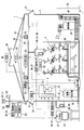
- the agricultural house 1 controls the inside of the house to an appropriate environment for growth by the control device 2 for the purpose of growing a predetermined crop 4 in the house.
- the environmental factors to be controlled are, for example, room temperature, humidity, carbon dioxide concentration, solar radiation amount, etc. in the house.
- the control device 2 controls the operation of various temperature adjusting devices, humidity adjusting devices, air flow adjusting devices, carbonic acid concentration adjusting devices, water supply adjusting devices, solar radiation amount adjusting devices and the like in order to properly control these environmental factors. It can be an environmental control controller.
- Agricultural house 1 has various sensors that measure wind direction, wind speed, sunshine, precipitation, house temperature, humidity, carbon dioxide concentration, etc., opening / closing of house skylights and curtains, control of air conditioner, generation of mist And various control devices that generate carbon dioxide and the like, and a control device 2.
- the control device 2 outputs a control signal corresponding to a control index obtained from measured values (for example, temperature, humidity, carbon dioxide concentration) at a plurality of locations in the house main body 3 to various adjustment devices, so that the situation inside and outside the house is obtained. Accordingly, the control is automatically performed so that the growth environment of the crop 4 is optimized.
- the agricultural house 1 is also an air conditioning management system that can increase the yield by promoting photosynthesis by automatically controlling the temperature, carbon dioxide concentration, etc. in greenhouse cultivation of tomatoes.
- the house body 3 includes, for example, a frame configured by combining metal members as structural materials, and a covering material supported by the frame.
- a covering material a transparent synthetic resin film or glass is used.
- the house main body 3 illustrated in FIG. 1 integrally includes a gable-like roof portion and two sets of side wall portions that support the roof portion and face each other, but this form is an example, and the house main body 3 This is not to limit the configuration of 3. Moreover, it does not prevent using other materials for the house main body 3, or forming in another shape.
- the crop 4 is cultivated on a soil in a predetermined container such as a bed 38 provided in the house body 3.
- a predetermined container such as a bed 38 provided in the house body 3.
- the nutrient solution containing water and fertilizer is supplied to the soil through the pipe by the water feeder 37, the crop 4 grows by absorbing nutrients from the soil.
- a predetermined number of beds 38 are arranged in the house so as to form a line at equal intervals.
- the water supply machine 37 is a water supply pump controlled by the control device 2.
- the control device 2 operates the water supply 37 at a predetermined time zone in one day to supply a target amount of nutrient solution to the soil.
- the control apparatus 2 controls the water supply machine 37 so that the supply amount of nutrient solution may be adjusted with respect to the target amount according to the amount of solar radiation detected by the solar radiation sensor 52.
- the circulation fan 33 is a blower installed at a position higher than the crop 4, the humidity sensor 57, and the side window 31 in the upper part of the house body 3.
- the circulation fan 33 is controlled by the control device 2, and circulates the gas in the house main body 3 to be distributed throughout.
- the circulation fan 33 constitutes an airflow forming device that forms an airflow in the house body 3 and around the crop 4, and promotes adjustment of humidity, temperature, carbon dioxide concentration, etc. in the house. It also contributes to promoting growth.
- the control device 2 obtains a control index by using the measured values of the temperature sensor 56, the humidity sensor 57, and the carbon dioxide sensor 58, which are provided in plural.
- the control device 2 operates the circulation fan 33 according to the control index obtained from the measured values in a plurality of locations in the house body 3 to increase or decrease the room temperature in the house, and to adjust the carbon dioxide concentration and humidity to the house. Control to make uniform inside.
- the control device 2 determines the control index by, for example, calculation for obtaining a maximum value, a minimum value, an average value, etc. for a plurality of measurement values.
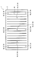
- FIG. 2 shows an example of an environmental value detection location in the house body 3 by a plurality of sensors.
- the temperature sensors 56 are arranged in the house body 3 in plan view, with three equal intervals in the arrangement direction in which the plurality of beds 38 are arranged, and both ends in the direction in which each bed 38 extends. It is a room temperature detecting means that is installed in a total of nine in the center.
- the plurality of temperature sensors 56 are installed at both the corners of the house and the vicinity of the side walls, such as where the airflow is difficult to be formed and the airflow is stagnation and where the airflow is relatively easy to form such as the center. Therefore, it contributes to the implementation of environmental control from multiple perspectives.
- the control device 2 determines the control index by the above-described calculation using the measured values of the plurality of temperature sensors 56. 2 may be replaced with a humidity sensor 57 or a carbon dioxide sensor 58. In this case as well, the above-described operational effects are obtained as in the case of the temperature sensor 56, and the control device 2 uses the measured values of the plurality of humidity sensors 57 or carbon dioxide sensors 58 to calculate the control index by the above-described calculation. decide.
- the circulation fan 33 is installed in a form in which a place where an airflow is formed in the house can be selected.
- the circulation fan 33 is movable by being fixed to a rail or the like extending horizontally or vertically in the house. It is preferable.
- the mist generator 34 includes a mist tube installed at a position higher than the crop 4, the humidity sensor 57, and the side window 31 in the upper part of the house.
- the mist tube has a plurality of nozzles attached to the wall of the tube to be watered, and is configured such that water is sprayed from the nozzles by adjusting the pressure that is passed through the tube by a pump or the like. Yes. Therefore, since the mist tube ejects water in the form of a mist, the mist falls from the upper part in the house over a relatively long time, and the humidity in the house can be gradually increased. Further, by operating the circulation fan 33 together with the mist ejection from the mist generator 34, the mist can be quickly spread in the house, and the humidity can be increased.
- the mist generator 34 is controlled by the control device 2.
- the control device 2 controls the mist generator 34 to operate in a predetermined time zone of the day to eject a target amount of fog so that the humidity environment in the house falls within the target range.
- the control device 2 controls the humidity environment in the house to a target range by adjusting the amount of mist ejected by the mist generator 34 according to the control index obtained from the measured humidity values at a plurality of locations in the house body 3. .
- control device 2 controls the mist generator 34 so as to increase or decrease the supply amount of the mist with respect to the target amount according to the amount of solar radiation detected by the solar radiation sensor 52. Further, when the relative humidity in the house measured by the humidity sensor 57 is low, the control device 2 operates the mist generator 34 to supply mist into the house and perform control to increase the relative humidity.
- the mist generator 34 is operated mainly when humidification is performed. However, the mist generator 34 can be operated as a temperature lowering device that lowers the room temperature by promoting vaporization heat action by supplying mist into the house.
- the house body 3 is provided with a curtain 32 that can be opened and closed between a closed state in which external light incident from the roof portion is blocked and an open state in which the crop 4 is irradiated without external light incident from the roof portion. ing.
- the curtain 32 is used in combination with a cooling device or a heating device to keep the house cold or warm.
- the roof part of the house main body 3 is provided with a skylight 30 that can be opened and closed, and by adjusting the opening amount of the skylight 30, it is possible to adjust the air ventilation resistance and the ventilation amount when taking outside air into the house.
- the side window 31 which can be opened and closed is provided in the side wall part of the house main body 3, and by adjusting the opening amount of the side window 31, the ventilation resistance and ventilation amount of the air when taking in outside air in a house are adjusted. Can be adjusted. That is, the skylight 30 and the side window 31 are windows that can control the airflow flowing in and out of the house.
- Each of the curtain 32, the skylight 30, and the side window 31 is driven by a power source such as a motor and is controlled by the control device 2.
- a power source such as a motor
- the control device 2 controls to drive the curtain 32 in the closing direction when the temperature in the house is lowered, and to drive the curtain 32 in the opening direction when increasing the temperature in the house.
- the control device 2 controls the curtain 32 to be closed and keeps the heat.
- the skylight 30 and the side window 31 are opened and closed so that the room temperature in the house approaches the target temperature during the daytime, and is closed at night and in the winter.
- the control device 2 adjusts the opening / closing amounts of the skylight 30, the side window 31, the curtain 32, etc. according to the control index obtained from the measured temperature values at a plurality of locations in the house body 3, and targets the temperature environment in the house. Control to range.
- the speed at which outside air is taken into the house body 3 can be adjusted by adjusting the opening amount of the skylight 30 and the side window 31.
- the skylight 30 and the side window 31 can adjust the temperature using the temperature difference between the inside and outside of the house body 3 by taking outside air into the internal space of the house body 3. For example, in the summer or on a sunny day, the curtain 32 is closed and the opening amount of the skylight 30 and the side window 31 is largely controlled, which contributes to suppressing an increase in the room temperature of the house body 3.
- the circulation fan 33, the skylight 30 and the side window 31 constitute an airflow forming device in the agricultural house 1.
- the skylight 30 and the side window 31 can also comprise an airflow formation apparatus independently, even if the circulation fan 33 is not drive
- outside air having a flow velocity of a certain level or more can be taken into the house body 3 depending on the outside wind direction, and an air flow including outside air inflow is formed in the house. it can.
- the circulation fan 33 is thus used as an air flow forming device and can be used not only for adjusting the room temperature and humidity, but also for diffusing carbon dioxide in the house.
- the agricultural house 1 includes a heat pump device 35 that functions as an air conditioner capable of supplying warm air and cold air into the house.
- the main body of the heat pump device 35 is installed outside the house, and the conditioned air can be blown to a predetermined position such as around the crop 4 through a duct extending from the main body.
- the ambient temperature of the crop 4 can be controlled by the conditioned air from the heat pump device 35.
- the heat pump device 35 constitutes a cycle in which the refrigerant circulates in a circuit in which a plurality of heat exchangers, a compressor, a decompression device, and the like are connected in a ring shape.
- the heat pump device 35 functions as a temperature raising device when the outside air heated by the heat radiating heat exchanger by the heat radiating action of the refrigerant is blown as warm air, and the outside air cooled by the cooling heat exchanger by the heat absorbing action of the refrigerant. Functions as a temperature lowering device.
- the control device 2 controls the heat pump device 35 so that the room temperature around the crop 4 is maintained at a target temperature suitable for growth.
- the agricultural house 1 includes a heater 36 that can supply warm air into the house.
- the heater 36 is an air conditioner that can blow warm air to a predetermined position such as around the crop 4.
- the heater 36 functions as a temperature raising device that can raise the temperature around the crop 4 with the heating air.
- the heater 36 supplies air heated by an electric heater, a hot water heater, a combustion heater, or the like into the house.
- the control device 2 controls the heater 36 so that the room temperature around the crop 4 is maintained at a target temperature suitable for growth.
- the control device 2 controls the operation of the heat pump device 35, the heater 36, etc. according to the control index obtained from the temperature measurement values at a plurality of locations in the house body 3, and controls the temperature environment in the house to the target range. To do.
- the agricultural house 1 includes a carbon dioxide generator 39 that supplies carbon dioxide into the house.
- the control device 2 controls the carbon dioxide generator 39 so as to keep the carbon dioxide concentration in the house, particularly around the crop 4 appropriately.
- the control device 2 operates the carbon dioxide generator 39 during a predetermined time of the day to adjust the carbon dioxide concentration in the house to a target value. Therefore, the carbon dioxide generator 39 is a photosynthesis promoting device.
- the control device 2 controls the operation of the carbon dioxide generator 39 in accordance with the control index obtained from the measured values of the carbon dioxide concentration at a plurality of locations in the house body 3 to bring the carbon dioxide concentration environment in the house into the target range. Control.
- the agricultural house 1 includes a plurality of various sensors that measure environmental information related to the growth of the crop 4.
- the various sensors include, for example, a wind direction sensor 50, a wind speed sensor 51, a solar radiation sensor 52, a raindrop sensor 53, an outdoor temperature sensor 54, an outdoor humidity sensor 55, an indoor temperature sensor 56, an indoor humidity sensor 57, and a carbon dioxide sensor 58. It is an environmental sensor in the agricultural house 1 including the above.
- the wind direction sensor 50 detects the wind direction outside the house body 3.
- the wind direction information detected by the wind direction sensor 50 is input to the control device 2 and is used for opening control of these windows as the wind direction with respect to the skylight 30 and the side window 31.
- the wind speed sensor 51 detects the wind speed outside the house body 3.
- the wind speed information detected by the wind speed sensor 51 is input to the control device 2 and used for opening control of these windows as the wind speed for the skylight 30 and the side window 31.
- the solar radiation sensor 52 detects the amount of solar radiation falling on the house body 3.
- the amount of solar radiation information detected by the solar radiation sensor 52 is input to the control device 2 and used for estimating the amount of heat flowing into the house, and used for opening / closing control of the curtain 32 and room temperature control.
- the detected amount of solar radiation can also be used to determine whether it is rainy or at night, and during sunny days.
- the raindrop sensor 53 is a rain sensor provided outside the house body 3 and capable of detecting the presence or absence of rainfall.
- the raindrop sensor 53 is, for example, a sensor that detects rain adhering to the panel as moisture, and detects electrical resistance between predetermined electrodes. The detected value of electrical resistance is input to the control device 2, and the control device 2 determines that rain is currently falling when the detected value is equal to or less than a certain resistance value.
- the raindrop sensor 53 may be a sensor that detects rain adhering to the panel as water pressure. In this case, the pressure detected by the raindrop sensor 53 is input to the control device 2, and the control device 2 determines that it is currently raining when the detected value is equal to or greater than a certain pressure value.
- the temperature sensor 54 detects the temperature of the outside air outside the house body 3 and sends it to the control device 2.
- the humidity sensor 55 detects the humidity of the outside air outside the house body 3 and sends it to the control device 2.
- the plurality of temperature sensors 56 detect the temperature inside the house body 3, for example, the temperature around the crop 4, and send the temperature environment value to the control device 2.
- the plurality of humidity sensors 57 are humidity detection means for detecting the humidity in the room of the house body 3, for example, the humidity around the crop 4, and sends the humidity environment value to the control device 2.
- the plurality of carbon dioxide sensors 58 are carbon dioxide concentration detection means for detecting the carbon dioxide concentration in the room of the house body 3, for example, the carbon dioxide concentration around the crop 4, and sends the carbon dioxide environment value to the control device 2.
- the environment in which the crop 4 grows in the house body 3 changes by controlling various temperature adjusting devices, humidity adjusting devices, air volume adjusting devices, carbonic acid concentration adjusting devices, water supply adjusting devices, solar radiation amount adjusting devices, and the like.
- the temperature adjusting device includes the skylight 30, the side window 31, the curtain 32, the circulation fan 33, the mist generator 34, the heat pump device 35, the heater 36, and the like that can be controlled to adjust the room temperature in the house.
- the humidity adjusting device can be configured by a mist generator 34, a heat pump device 35, and the like that can be controlled so as to adjust the relative humidity in the house.
- the air volume adjusting device can be configured by a skylight 30, a side window 31, a circulation fan 33, and the like that can be controlled to form an airflow in the house.
- the carbonic acid concentration adjusting device can be constituted by a carbon dioxide generator 39 or the like controlled to adjust the carbon dioxide concentration in the house.
- the water supply adjustment device can be constituted by a water supply 37 that is controlled to adjust water supply to the crop 4.
- the solar radiation amount adjusting device can be configured by a curtain 32 that can be controlled to adjust the solar radiation amount flowing into the house.
- the control device 2 adjusts the water supply pressure of the water supply 37, opens and closes the curtain 32, adjusts the opening amounts of the skylight 30 and the side window 31, a circulation fan 33, a mist generator 34, a carbon dioxide generator 39, a heater 36, In addition, each operation and stop of the heat pump device 35 are controlled.
- An electromagnetic relay that turns on and off the power supply to each device is used to start and stop energization of each adjusting device.
- the control device 2 is housed in a housing installed inside the house body 3 or outside the house body 3.
- the control device 2 includes a device such as a microcomputer that operates according to a program as a main hardware element.
- the control device 2 includes an interface unit (hereinafter also referred to as an I / F unit) 20 to which each adjustment device and various sensors described above are connected, an arithmetic processing unit 21, and a storage unit 22 that stores various data.
- the arithmetic processing unit 21 performs an operation according to a predetermined program using environmental information acquired from various sensors through the I / F unit 20 and various data stored in the storage unit 22.
- the I / F unit 20 and the arithmetic processing unit 21 correspond to a control unit of the control device 2.
- the I / F unit 20 operates each adjustment device based on the calculation result by the calculation processing unit 21.
- the I / F unit 20 is connected to a terminal device serving as a user interface, such as a personal computer 23, a control panel, a portable terminal, and the like.
- the user can use the operation panel of the control device 2, the operation unit of the personal computer 23, the control panel, the terminal device, etc. to set the environment such as the room temperature in the house, set the time, etc.
- the current operating state can be confirmed through the screen.
- control device 2 In parallel with the environmental control in the house that is always performed to promote the growth of the crop 4. That is, the control device 2 constantly monitors whether or not various sensors for measuring environmental values such as temperature, humidity, and carbon dioxide concentration are abnormal. Fail-safe processing is performed to improve automatically.
- the case where various sensors are determined to be abnormal is a case where a sensor that outputs a measurement value that is clearly recognized as abnormal among a plurality of sensors is detected. If such a sensor exists, when the control index is obtained using environmental values at multiple locations in the house as described above, the control index deviates from the appropriate value, so appropriate environmental control in the house is implemented. Can not. Therefore, environmental control that inhibits the growth of the crop 4 may be performed.
- the abnormality of the sensor may occur due to a failure of the sensor itself, a disconnection of a communication line, a short circuit, adhesion of a foreign substance at a sensor detection unit, or the like.
- the control shown in FIG. 3 is always executed if the agricultural house 1 is growing the crop 4 in order to avoid such a situation.
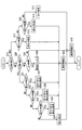
- the process of the flowchart shown in FIG. 3 is executed by the control device 2.
- the flowchart of FIG. 3 shows a processing procedure in a case where the number of temperature sensors for measuring room temperature is three or less, as an example of a plurality of sensors.
- S10 it is determined whether or not the number of temperature sensors 56 used for determining the control index is two. If there are two temperature sensors 56, “YES” is determined in S 10, and it is determined in next S 11 whether or not a specific first sensor out of the two temperature sensors 56 has failed. When the measured value of the first sensor is a low value or a high value that is clearly not normal room temperature, a sensor abnormality condition of the first sensor is satisfied. An upper limit allowable value and a lower limit allowable value are set in advance, and in S11, it may be determined that the sensor abnormality condition is satisfied when the upper limit allowable value is exceeded or less than the lower limit allowable value.
- the measured value of the first sensor cannot be used for determining the control index because the first sensor out of the two sensors is abnormal. Accordingly, in S15, the measurement value of the other second sensor is adopted to determine the control index, and the process for obtaining the control index is executed using this measurement value. And in the agricultural house 1, temperature control according to this control parameter
- the abnormal state of the sensor is notified to the outside and measures such as repair are promoted, and the state in which the environment is controlled by an inappropriate control index until the repair is performed can be eliminated. It becomes possible. Further, this flowchart is executed at a predetermined time interval, for example, at an interval of 30 seconds. Therefore, when a predetermined time elapses after the end, the process is resumed from the process of S10, and this flowchart is always executed every predetermined time.
- the user who recognizes the sensor abnormality by the process of S50 can try repair by himself or arrange repair for others. Until the repair is completed, the control device 2 continues the emergency improvement control based on the control index excluding the abnormal measurement value by executing the processes of S11, S15, and S50.
- the sensor abnormal condition of the second sensor is satisfied.
- an upper limit allowable value and a lower limit allowable value may be determined in advance, and in S21, it may be determined that the sensor abnormality condition is satisfied when the upper limit allowable value is exceeded or the lower limit allowable value is not reached.
- the measured value of the second sensor cannot be used for determining the control index because the second sensor of the two sensors is abnormal. Therefore, in S14, the measurement value of the other first sensor is adopted to determine the control index, and the process for obtaining the control index is executed using this measurement value. And in the agricultural house 1, while performing temperature control according to this control parameter
- the number of temperature sensors 56 is not two, it is determined as “NO” in S10, and it is determined in next S20 whether or not the number of temperature sensors 56 used for determining the control index is three. If there are three temperature sensors 56, “YES” is determined in S20, and it is determined in the next S21 whether or not a specific first sensor out of the three temperature sensors 56 has failed.
- S21 If it is determined in S21 that the sensor abnormal condition is not satisfied for the first sensor, it is determined in S22 whether or not the specific second sensor has failed. If it is determined in S22 that the sensor abnormal condition is satisfied for the second sensor, the second sensor out of the three sensors is abnormal, and the measured value of the second sensor cannot be used for determining the control index. Therefore, in S26, the measured values of the first sensor and the third sensor are adopted to determine the control index, and the process of obtaining the control index is executed using the measured value. And in the agricultural house 1, while performing temperature control according to this control parameter
- the abnormal state of the sensor is notified to the outside, and countermeasures such as repair are promoted, and the state in which the environment is controlled by an inappropriate control index until repair is eliminated. can do.
- the control device 2 sets 25 ° C. as an example of a substitute value for room temperature, and executes processing using this set temperature as a control index.
- This predetermined temperature is set to a temperature that does not adversely affect the growth of the crop 4.
- the predetermined temperature may be set to a temperature according to the current season, time, and the like. Moreover, you may make it employ
- control apparatus 2 of embodiment brings about is demonstrated.
- the control device 2 detects a sensor that outputs an abnormal value among the plurality of sensors, the control device 2 notifies that there is an abnormal sensor (S50). Further, the control device 2 obtains a control index using the environmental values measured by the remaining sensors excluding the sensor that outputs the abnormal value (S14, S15, S25, S26, S27), and the house according to the control index. Control the temperature environment, humidity environment or carbon dioxide environment inside.
- the control device 2 calculates a control index by calculating any one of the maximum value, the minimum value, and the average value for the environmental values measured by the remaining sensors excluding the abnormal sensors. According to this, when an environmental value changes with places in a house, the control parameter
- the control device 2 When the control device 2 detects that an abnormal value is output for all of the plurality of sensors, the control device 2 notifies that an abnormal sensor exists. Further, the control device 2 controls the temperature environment, humidity environment, or carbon dioxide environment in the house according to a predetermined control index that does not adversely affect the growth of the crop 4.
- the predetermined control index is set to a temperature, humidity, and carbon dioxide concentration that do not adversely affect the growth of the crop 4.
- the predetermined control index may be set to an index according to the current season, time, and the like. In addition, an index obtained based on the past performance in a predetermined number of days may be adopted as the predetermined control index.
- the agricultural house 1 has a temperature environment according to a plurality of sensors that measure environmental values at a plurality of locations in the house and a control index that is obtained using the environmental values at a plurality of locations measured by the plurality of sensors.
- a control device 2 for controlling a humidity environment or a carbon dioxide environment.
- the control device 2 detects a sensor that outputs an abnormal value among a plurality of sensors, the control device 2 notifies that an abnormal sensor exists. Further, the control device 2 obtains a control index using the environmental value measured by the remaining sensors excluding the sensor that outputs the abnormal value, and determines the temperature environment, humidity environment, or carbon dioxide environment in the house according to the control index. Control.
- this agricultural house 1 when an abnormal sensor is detected among a plurality of sensors that measure environmental values at a plurality of locations, an abnormality is notified and a control index is obtained using the remaining normal sensors. Ask. According to this process, even if an abnormality occurs in the sensor, the environmental control in the multi-purpose and large-scale house can be continued, so that adverse effects on the crop 4 from the abnormality notification to the repair are suppressed. An agricultural house 1 can be provided. Therefore, according to the agricultural house 1, even if any one of the plurality of sensors has an abnormality such as a failure, the environmental deterioration can be urgently improved and multi-view environmental control can be provided.
- the sensor abnormality control is described when the number of temperature sensors 56 is three or less. However, if the number of sensors used for determining the control index is two or more, the number is three or less. It is not limited. If the number of sensors is 4 or more, the flowchart described above will change the determination process related to the number of sensors in S10 and S20 to match the number of sensors used to determine the control index, and identify the faulty sensor. The above-described processes for performing are sequentially executed.
- control device 2 may be configured to receive outputs from various sensors and to give instructions to each adjustment device through an interface unit included in the personal computer or an interface unit added to the personal computer. Good. That is, the personal computer can function as the control device 2 by executing the program on the personal computer.
- the I / F unit 20 of the control device 2 may include a communication interface unit that acquires weather forecast information from the outside.
- the control device 2 predicts the ambient humidity of the crop 4 from the weather forecast information acquired through the I / F unit 20 and adjusts the amount of water supplied to the bed 38 by the water feeder 37 based on the prediction result. be able to.
- the tomato is an example of the crop 4, but the crop 4 is not limited to the tomato, and may be other vegetables and fruits.
Landscapes
- Life Sciences & Earth Sciences (AREA)
- Environmental Sciences (AREA)
- Greenhouses (AREA)
Abstract
作物(4)を生育するための農業用ハウス(1)において、制御装置(2)は、複数個のセンサ(56,57,58)によって測定されるハウス内の複数箇所の環境値を用いて求めた制御指標に応じて、ハウス内における温度環境、湿度環境または二酸化炭素環境を制御する。制御装置(2)は、複数個のセンサのうち、異常値を出力するセンサを検出した場合には、異常な状態のセンサが存在することを報知するとともに、異常値を出力するセンサを除いた残りのセンサによって測定される環境値を用いて制御指標を求め、制御指標に応じてハウス内における温度環境、湿度環境または二酸化炭素環境を制御する制御部を備える。
Description
本出願は、2015年6月30日に出願された日本特許出願2015-130928号に基づくもので、ここにその記載内容を援用する。
本開示は、作物を栽培するハウス内の環境を制御する制御装置及び農業用ハウスに関する。
農業用ハウスにおいては、その大きさや形状、また各種の環境調整機器やセンサの設置場所に応じて、ハウス内の温度、湿度、風速等の環境が場所によって異なることがある。言い換えれば、栽培される作物の設置環境は、ハウス内において均一ではない場合がある。したがって、ハウス内の環境を適正に保つには、場所によって異なる温度等の環境値を十分に考慮した環境制御が求められる。例えば、ハウス内の複数の場所において複数個のセンサを用いた環境値を取得し、取得した複数の環境値を用いて、多観点的でハウス全体を考慮した大局的な環境制御を実施することが望まれる。
特許文献1には、特定の温度センサが検出する温度を、基準温度として用いて環境制御を実施するハウス用暖房機の制御方法が開示されている。
特許文献1によれば、特定の温度センサによって検出される基準温度が、例えば、送風機及びバーナ、またはポンプ及びボイラを運転するか否かの重要なデータとなる。さらに、特許文献1には、基準温度を検出する温度センサが作動不良になった場合には、残りの温度センサのいずれか一つを、作動不良状態の温度センサに代わってハウス内の基準温度を検出するためのセンサとして用いることが開示されている。
このように特許文献1では、特定の温度センサが故障した場合に、他の温度センサが代わりに基準温度を検出するものにすぎない。したがって、特許文献1では、複数個のセンサによる検出値を用いて、ハウス内の異なる場所の環境を考慮した多観点的な環境制御を実施することはできない。
本開示の目的は、複数個のセンサのうちいずれかのセンサに故障等の異常があった場合でも、環境悪化を緊急改善するとともに多観点的な環境制御を実施できる制御装置及び農業用ハウスを提供することである。
本開示の一態様では、作物を生育するための農業用ハウスにおいて、複数個のセンサによって測定されるハウス内の複数箇所の環境値を用いて求めた制御指標に応じて、ハウス内における温度環境、湿度環境または二酸化炭素環境を制御する制御装置は、複数個のセンサのうち、異常値を出力するセンサを検出した場合には、異常な状態のセンサが存在することを報知するとともに、異常値を出力するセンサを除いた残りのセンサによって測定される環境値を用いて制御指標を求め、この制御指標に応じてハウス内における温度環境、湿度環境または二酸化炭素環境を制御する制御部を備える。
これによれば、ハウス内の複数の場所における環境値を測定する複数個のセンサのうち異常なセンサを検出した場合に、異常の報知を行うとともに、残りの正常なセンサを用いて制御指標を求め、多観点的で大局的な環境制御を継続できる。これにより、異常の報知から修理完了までの間の作物に及ぼしうる悪影響を抑制する制御装置を提供できる。したがって、この制御装置によれば、複数個のセンサのうちいずれかのセンサに故障等の異常があった場合でも、環境悪化を緊急改善するとともに多観点的な環境制御を実施できる。
本開示の一態様において、農業用ハウスは、作物を生育するためのハウス内においてそれぞれ環境値を測定することによりハウス内における複数箇所の環境値を測定する複数個のセンサと、複数個のセンサによって測定されるハウス内の複数箇所の環境値を用いて求めた制御指標に応じて、ハウス内における温度環境、湿度環境または二酸化炭素環境を制御する制御装置と、を備える。制御装置は、複数個のセンサのうち、異常値を出力するセンサを検出した場合には、異常な状態のセンサが存在することを報知するとともに、異常値を出力するセンサを除いた残りのセンサによって測定される環境値を用いて制御指標を求め、制御指標に応じてハウス内における温度環境、湿度環境または二酸化炭素環境を制御する。
これによれば、ハウス内の複数場所の環境値を測定する複数個のセンサのうち異常なセンサを検出した場合に、異常の報知を行うとともに、残りの正常なセンサを用いて制御指標を求め、多観点的で大局的な環境制御を継続できる農業用ハウスを提供できる。これにより、農業用ハウスは、異常の報知から修理までの間の作物への悪影響を抑制することができる。したがって、この農業用ハウスによれば、複数個のセンサのうちいずれかのセンサに故障等の異常があった場合でも、環境悪化を緊急改善するとともに多観点的な環境制御を実施できる。
農業用ハウス1は、ハウス内で所定の作物4を生長させることを目的として、制御装置2によって、ハウス内を生長に適正な環境に制御する。制御される環境因子は、例えば、ハウス内における室温、湿度、二酸化炭素濃度、日射量等である。制御装置2は、これらの環境因子を適正に制御するために、各種の温度調整機器、湿度調整機器、風量調整機器、炭酸濃度調整機器、給水調整機器、日射量調整機器等の作動を制御することができる環境制御コントローラである。
実施形態について、図1~図3を参照して説明する。農業用ハウス1は、風向き、風速、日照、降水の有無、ハウス内の温度、湿度、二酸化炭素濃度等を計測する各種センサと、ハウスの天窓やカーテンの開閉、空調装置の制御、ミストの発生、二酸化炭素の発生等を行う各種調整機器と、制御装置2とを備える。制御装置2は、ハウス本体3内における複数箇所の測定値(例えば、温度、湿度、二酸化炭素濃度)から求めた制御指標に応じた制御信号を各種調整機器に出力して、ハウス内外の状況に応じて作物4の生育環境が最適となるよう自動的に制御する。例えば作物4がトマトである場合には、農業用ハウス1は、トマトの温室栽培において温度、二酸化炭素濃度等を自動制御することで光合成を促進して収穫量を増加できる空調管理システムでもある。
ハウス本体3は、例えば、構造材としての金属製部材を組み合わせて構成されたフレームと、フレームにより支持された被覆材とを備える。被覆材は、透光性を有する合成樹脂フィルムやガラスが用いられる。図1に図示するハウス本体3は、切妻状の屋根部と、屋根部を支持し各組互いに対向する二組の側壁部と、を一体に備えるが、この形態は一例であって、ハウス本体3の構成を限定する趣旨ではない。また、ハウス本体3に他の材料を用いることや他の形状に形成することを妨げるものではない。
作物4は、ハウス本体3内に設けられたベッド38等の所定の容器内の用土において栽培されている。給水機37によって、水と肥料とを含んだ養液がパイプを通じて用土に供給されることにより、作物4は用土から栄養分を吸収して生育する。ベッド38は、ハウス内において所定の個数、均等の間隔をあけて列をなすように設置されている。
給水機37は、制御装置2によって制御される給水ポンプである。制御装置2は、1日のうち所定の時間帯に給水機37を運転して目標量の養液を用土に供給する。また、制御装置2は、日射センサ52によって検出された日射量に応じて、目標量に対して養液の供給量を加減するように給水機37を制御する。
循環扇33は、ハウス本体3内の上部において、作物4、湿度センサ57、側窓31よりも高い位置に設置された送風装置である。循環扇33は、制御装置2によって制御され、ハウス本体3内の気体を循環させて全体に行き渡らせる。このように循環扇33は、ハウス本体3内や作物4の周囲に気流を形成する気流形成装置を構成し、ハウス内における湿度、温度、二酸化炭素濃度等の調整を促し、また、作物4の生育を促すことにも寄与する。
制御装置2は、それぞれ複数個設けられる、温度センサ56、湿度センサ57、二酸化炭素センサ58の各測定値を用いて制御指標を求める。制御装置2は、ハウス本体3内における複数箇所の測定値から求めた制御指標に応じて循環扇33を運転することで、ハウス内の室温を上昇または低下させたり、二酸化炭素濃度や湿度をハウス内において均一化させたりする制御を行う。制御装置2は、例えば、複数の測定値についての最大値、最小値、平均値等を求める演算によって制御指標を決定する。
図2は、複数個のセンサによる、ハウス本体3内の環境値検出箇所の一例を示している。図2に示す一例では、温度センサ56は、平面視したハウス本体3内において、複数個のベッド38が並ぶ配列方向に等間隔をあけて3個、各ベッド38が延びる方向の両方の端と中央とに3個の計9個設置される室温検出手段である。このように複数個の温度センサ56は、ハウス内の四隅、側壁近傍など、気流が形成されにくく空気の流れがよどみやすい場所と、中央などの比較的気流が形成されやすい場所との両方に設置されるため、多観点的で大局的な環境制御の実施に寄与する。制御装置2は、これら複数個の温度センサ56の各測定値を用いて、前述した演算によって制御指標を決定する。また、図2に図示する各温度センサ56は、湿度センサ57や二酸化炭素センサ58に置き換えてもよい。この場合も温度センサ56の場合と同様に前述する作用効果を奏し、制御装置2は、これら複数個の湿度センサ57または二酸化炭素センサ58の各測定値を用いて、前述した演算によって制御指標を決定する。
また、循環扇33は、ハウス内において気流を形成する場所を選択可能な形態で設置されることが好ましく、例えば、ハウス内において横または縦に延びるレール等に固定されることによって可動式であることが好ましい。
ミスト発生器34は、ハウス内の上部において、作物4、湿度センサ57、側窓31よりも高い位置に設置されたミストチューブを備える。ミストチューブは、通水されるチューブの管壁に取り付けられた複数個のノズルを備え、ポンプ等によってチューブに通水される圧力を調節することによりノズルから水が噴霧されるように構成されている。したがって、ミストチューブは水を霧状に噴出させるため、霧はハウス内の上部から比較的時間をかけて落下し、ハウス内の湿度を徐々に上昇させることができる。また、ミスト発生器34による霧の噴出とともに循環扇33を運転することにより、ハウス内に霧を早く行き渡らせることができ、湿度の上昇を早めることもできる。
ミスト発生器34は、制御装置2によって制御される。制御装置2は、例えば1日のうち所定の時間帯にミスト発生器34を運転して目標量の霧を噴出し、ハウス内の湿度環境を目標範囲にするように制御する。制御装置2は、ハウス本体3内の複数箇所における湿度の測定値から求めた制御指標に応じてミスト発生器34による霧の噴出量を調整して、ハウス内の湿度環境を目標範囲に制御する。
また、制御装置2は、日射センサ52によって検出された日射量に応じて、目標量に対して霧の供給量を加減するようにミスト発生器34を制御する。また、制御装置2は、湿度センサ57によって測定されたハウス内の相対湿度が低い場合に、ミスト発生器34を運転してハウス内に霧を供給し、相対湿度を上昇させる制御を行う。また、ミスト発生器34は、主に加湿を行う場合に運転されるが、ハウス内にミストを供給することにより気化熱作用を促して室温を低下させる温度低下装置として運転することもできる。
ハウス本体3には、屋根部から入射する外光を遮光させる閉状態と、屋根部から入射する外光を遮光しないで作物4に照射させる開状態との間で開閉可能なカーテン32が設けられている。また、カーテン32は、冷房装置や暖房装置と併用されて、ハウス内を保冷したり保温したりする際に、活用される。さらにハウス本体3の屋根部には、開閉可能な天窓30が設けられ、天窓30の開量が調節されることにより、ハウス内に外気を取り込む際の空気の通気抵抗や換気量を調節できる。また、ハウス本体3の側壁部には、開閉可能な側窓31が設けられ、側窓31の開量が調節されることにより、ハウス内に外気を取り込む際の空気の通気抵抗や換気量を調節できる。つまり、天窓30や側窓31は、ハウスの内外を行き来する気流を制御可能な窓である。
カーテン32、天窓30、側窓31のそれぞれは、モータ等の動力源により駆動され、制御装置2によって制御される。カーテン32が開閉されると、外部からハウス内に流入する日射量を調節することになり、ハウス内の室温について温度上昇の速度を調節することができる。したがって、制御装置2は、ハウス内の温度を低下させる場合には、カーテン32を閉じる方向に駆動し、ハウス内の温度を上昇させる場合には、カーテン32を開く方向に駆動するように制御する。ただし、暖房装置と併用する場合や外気温度が室温よりも低い場合は、制御装置2はカーテン32を閉じるように制御して保温を行う。天窓30や側窓31は、例えば、昼間にはハウス内の室温を目標温度に近づけるように開閉され、夜間や冬季には閉じられる。制御装置2は、ハウス本体3内の複数箇所における温度の測定値から求めた制御指標に応じて天窓30、側窓31、カーテン32等の開閉量を調整して、ハウス内の温度環境を目標範囲に制御する。
天窓30や側窓31の開量を調節することにより、ハウス本体3の中に外気を取り入れる速度を調節することができる。また、天窓30や側窓31は、ハウス本体3の内部空間に外気を取り込むことにより、ハウス本体3の内外の温度差を利用して温度を調節することができる。例えば、夏季や晴天の日中には、カーテン32を閉じ、かつ天窓30や側窓31の開量を大きく制御することにより、ハウス本体3の室温の上昇を抑制することに寄与する。
循環扇33と天窓30や側窓31とは、農業用ハウス1における気流形成装置を構成する。また、天窓30や側窓31は、循環扇33が運転していない状態でも単独で気流形成装置を構成することもできる。つまり、循環扇33が運転され、天窓30や側窓31が開いている場合には、ハウス本体3の内部に外気を強制的に取り込むことができ、ハウス内に外気流入を含む気流を形成できる。また、天窓30や側窓31が開いている場合には、外部の風向によってはハウス本体3の内部に一定以上の流速をもつ外気を取り込むことができ、ハウス内に外気流入を含む気流を形成できる。循環扇33は、このように気流形成装置として使用されて、室温の調整や湿度の調節だけでなく、ハウス内の二酸化炭素を拡散させることにも使用できる。
農業用ハウス1は、暖気や冷気をハウス内に供給可能な空調装置として機能するヒートポンプ装置35を備える。ヒートポンプ装置35は、その本体がハウスの屋外に設置され、本体から延びるダクトを介して、作物4の周囲などの所定の位置に空調風を吹き出すことができる。ヒートポンプ装置35の空調風により、作物4の周囲の温度を制御することができる。
ヒートポンプ装置35は、複数個の熱交換器、圧縮機、及び減圧装置等を環状に配管で接続した回路において冷媒が循環するサイクルを構成する。ヒートポンプ装置35は、冷媒の放熱作用により放熱用熱交換器で加熱された外気を暖気として送風する場合は、温度上昇装置として機能し、冷媒の吸熱作用により冷却用熱交換器で冷却された外気を冷気として送風する場合は、温度低下装置として機能する。制御装置2は、作物4の周囲における室温を生育に適した目標温度に保つようにヒートポンプ装置35を制御する。
農業用ハウス1は、暖気をハウス内に供給可能な暖房機36を備える。暖房機36は、作物4の周囲などの所定の位置に暖気を吹き出すことができる空調装置である。暖房機36は、暖房風により、作物4の周囲の温度を上昇させることができる温度上昇装置として機能する。暖房機36は、例えば、電気ヒータ、温水式ヒータ、燃焼式ヒータ等により暖めた空気をハウス内に供給する。制御装置2は、作物4の周囲における室温を生育に適した目標温度に保つように暖房機36を制御する。制御装置2は、ハウス本体3内の複数箇所における温度の測定値から求めた制御指標に応じてヒートポンプ装置35、暖房機36等の運転を制御して、ハウス内の温度環境を目標範囲に制御する。
農業用ハウス1は、ハウス内に二酸化炭素を供給する炭酸ガス発生機39を備える。制御装置2は、光合成を促進するために、ハウス内、特に作物4の周囲における炭酸ガス濃度を適切に保つように炭酸ガス発生機39を制御する。制御装置2は、例えば、1日のうち所定の時間帯に炭酸ガス発生機39を運転してハウス内の二酸化炭素濃度を目標値となるように調整する。したがって、炭酸ガス発生機39は、光合成促進装置である。制御装置2は、ハウス本体3内の複数箇所における二酸化炭素濃度の測定値から求めた制御指標に応じて炭酸ガス発生機39の運転を制御して、ハウス内の二酸化炭素濃度環境を目標範囲に制御する。
農業用ハウス1は、作物4の生育に関わる環境情報を測定する複数個の各種センサを備える。各種センサは、例えば、風向センサ50、風速センサ51、日射センサ52、雨滴センサ53、屋外の温度センサ54、屋外の湿度センサ55、室内の温度センサ56、室内の湿度センサ57、二酸化炭素センサ58等を含む農業用ハウス1における環境センサである。
風向センサ50は、ハウス本体3の屋外における風向を検出する。風向センサ50により検出された風向情報は、制御装置2に入力されて、天窓30や側窓31に対する風向としてこれらの窓の開度制御に用いられる。風速センサ51は、ハウス本体3の屋外における風速を検出する。風速センサ51により検出された風速情報は、制御装置2に入力されて、天窓30や側窓31に対する風速としてこれらの窓の開度制御に用いられる。
日射センサ52は、ハウス本体3に降り注ぐ日射量を検出する。日射センサ52により検出された日射量情報は、制御装置2に入力されてハウス内に流入する熱量の見積もりに用いられ、カーテン32の開閉制御、室温制御に用いられる。また、検出された日射量は、雨天や夜間と、晴天の日中とを判断することにも用いることができる。
雨滴センサ53は、ハウス本体3の屋外に設けられた降雨の有無を検出可能な雨センサである。雨滴センサ53は、例えば、パネル上に付着した雨を水分として検出するセンサであり、所定の電極間の電気抵抗を検出する。電気抵抗の検出値は制御装置2に入力され、制御装置2は、検出値がある抵抗値以下の場合は雨が現在降っていると判定する。また、雨滴センサ53は、パネル上に付着した雨を水圧として検出するセンサであってもよい。この場合、雨滴センサ53が検出する圧力は制御装置2に入力され、制御装置2は、検出値がある圧力値以上の場合は雨が現在降っていると判定する。
温度センサ54は、ハウス本体3の屋外における外気の温度を検出し、制御装置2に送る。湿度センサ55は、ハウス本体3の屋外における外気の湿度を検出し、制御装置2に送る。複数個の温度センサ56は、ハウス本体3の室内における温度、例えば作物4の周囲の温度を検出してこの温度環境値を制御装置2に送る。複数個の湿度センサ57は、ハウス本体3の室内における湿度、例えば作物4の周囲の湿度を検出する湿度検出手段であり、この湿度環境値を制御装置2に送る。複数個の二酸化炭素センサ58は、ハウス本体3の室内における二酸化炭素濃度、例えば作物4の周囲の二酸化炭素濃度を検出する二酸化炭素濃度検出手段であり、二酸化炭素環境値を制御装置2に送る。
ハウス本体3の中で作物4が生長する環境は、各種の温度調整機器、湿度調整機器、風量調整機器、炭酸濃度調整機器、給水調整機器、日射量調整機器等を制御することによって変化する。前述のように、温度調整機器は、ハウス内の室温を調整するように制御可能な天窓30、側窓31、カーテン32、循環扇33、ミスト発生器34、ヒートポンプ装置35、暖房機36等により構成することができる。また、湿度調整機器は、ハウス内の相対湿度を調整するように制御可能なミスト発生器34、ヒートポンプ装置35等により構成することができる。また、風量調整機器は、ハウス内の気流を形成するように制御可能な天窓30、側窓31、循環扇33等により構成することができる。
また、炭酸濃度調整機器は、ハウス内の二酸化炭素濃度を調整するために制御される炭酸ガス発生機39等により構成することができる。また、給水調整機器は、作物4への給水を調整するために制御される給水機37等により構成することができる。また、日射量調整機器は、ハウス内に流入する日射量を調整するように制御可能なカーテン32等により構成することができる。
制御装置2は、給水機37の送水圧の調節、カーテン32の開閉、天窓30及び側窓31の開量の調節、循環扇33、ミスト発生器34、炭酸ガス発生機39、暖房機36、及びヒートポンプ装置35のそれぞれの運転と停止などを制御する。各調整機器への通電開始及び通電停止には、各装置への給電を入切する電磁リレーが用いられる。制御装置2は、ハウス本体3内またはハウス本体3の外部に設置された筐体に収納される。
制御装置2は、プログラムに従って動作するマイコンのようなデバイスを主なハードウェア要素として備える。制御装置2は、前述した各調整機器と各種センサとが接続されるインターフェイス部(以下、I/F部ともいう)20と、演算処理部21と、各種データを記憶する記憶部22と、を備える。演算処理部21は、I/F部20を通して各種センサから取得した環境情報と、記憶部22に格納した各種データとを用いて所定のプログラムにしたがった演算を行う。I/F部20及び演算処理部21が、制御装置2の制御部に相当する。
I/F部20は、演算処理部21による演算結果に基づいて各調整機器を操作する。I/F部20には、ユーザインターフェイスとなる端末装置、例えば、パーソナルコンピュータ23、コントロールパネル、携帯用端末機等が接続される。使用者は、制御装置2の操作盤、パーソナルコンピュータ23の操作部、コントロールパネル、端末装置等を使用してハウス内における室温等の環境設定、時刻合わせ等を行うことができ、端末装置の表示画面を通じて現在の運転状態を確認することができる。
次に、制御装置2が実行するセンサ異常時制御の一例について図3のフローチャートを参照して説明する。この制御は、作物4の生育促進のために常時実施するハウス内の環境制御と同時並行に行われる。すなわち、制御装置2は、温度、湿度、二酸化炭素濃度等の環境値を測定する各種の複数個のセンサが異常であるか否かを常に監視し、異常判定した場合には、この状態を緊急的に改善するためのフェイルセーフ処理を実行する。
各種のセンサが異常判定される場合とは、複数個のセンサのうち、明らかに異常であると認められる測定値を出力するセンサを検出した場合である。このようなセンサが存在すると、前述のようにハウス内の複数箇所の環境値を用いて制御指標を求めた場合に、制御指標が適正値から乖離するため、ハウス内の適正な環境制御を実施できない。したがって、作物4の生育を阻害するような環境制御を行ってしまうことがある。例えば、センサの異常は、センサ自体の故障、通信線の断線、短絡、センサの検知部における異物の付着等により、起こりうる。
センサの異常状態が長引くと、作物4が適正に生長できない、あるいは商品にならない等の大きな損失が発生しうる。特に使用者が短時間でセンサの異常に気がつかない場合、例えば、留守にしている場合、農業用ハウスから離れた場所にいる場合、就寝中である場合等には、異常を報知するための警報が発せられても、深刻な事態に至ってしまうことがある。
図3に示す制御は、このような事態を回避するために、農業用ハウス1が作物4を生育している状態であれば、常時実行される。図3に示すフローチャートの処理は、制御装置2によって実行される。また、図3のフローチャートは、複数個のセンサの例を代表して、室温を測定する温度センサが3個以下である場合についての処理手順を示している。
まずS10では、制御指標の決定に用いられる温度センサ56の個数が2個であるか否かを判定する。温度センサ56が2個である場合はS10で「YES」と判定され、次のS11で2個の温度センサ56のうち特定の第1センサが故障しているか否かを判定する。第1センサの測定値が通常の室温でないことが明らかである低値や高値である場合には、第1センサのセンサ異常条件が成立する。あらかじめ上限許容値及び下限許容値を定め、S11では、上限許容値を超える場合や下限許容値未満である場合にセンサ異常条件が成立すると判定してもよい。
S11で第1センサについてセンサ異常条件が成立していると判定すると、2個のセンサのうち第1センサが異常であるため、第1センサの測定値を制御指標の決定に用いることはできない。したがって、S15で、もう一つの第2センサの測定値を制御指標を決定するために採用し、この測定値を用いて制御指標を求める処理を実行する。そして、農業用ハウス1では、この制御指標に応じた温度制御が行われる。さらにS50に進み、特定の第1センサが異常状態であることを使用者等に報知する異常警報を発して、本フローチャートを終了する。この異常状態の報知は、点灯、点滅などの表示、音声、または制御装置2による携帯端末等への情報送信によって実施することもできる。S50の異常警報処理により、使用者等は、異常状態であるセンサを改善するための修理を依頼することができる。
このS11、S15、S50の処理により、センサの異常状態を外部に知らせて修理等の対策を促すとともに、修理実施までの間に不適切な制御指標によって環境制御してしまう状態を解消することが可能になる。また、本フローチャートは、所定時間間隔、例えば30秒間隔で実行する。したがって、終了後、所定時間経過するとS10の処理から再開することになり、本フローチャートは、所定時間毎に常時実行される。
S50の処理によってセンサ異常を認識した使用者等は、自身で修理を試みたり、他者に修理の手配をしたりすることができる。修理が完了するまでの間は、制御装置2は、S11、S15、S50の処理を実行することで、異常な測定値を除いた制御指標に基づいた緊急改善制御を実施し続ける。
S11で第1センサについてセンサ異常条件が不成立であると判定すると、S12でもう一つの第2センサが故障しているか否かを判定する。第2センサの測定値が通常の室温でないことが明らかである低値や高値である場合には、第2センサのセンサ異常条件が成立することになる。第2センサについて、あらかじめ上限許容値及び下限許容値を定め、S21では、上限許容値を超える場合や下限許容値未満である場合にセンサ異常条件が成立すると判定してもよい。
S12で第2センサについてセンサ異常条件が成立していると判定すると、2個のセンサのうち第2センサが異常であるため、第2センサの測定値を制御指標の決定に用いることはできない。したがって、S14で、もう一つの第1センサの測定値を制御指標を決定するために採用し、この測定値を用いて制御指標を求める処理を実行する。そして、農業用ハウス1では、この制御指標に応じた温度制御が行われるとともに、前述のS50に進み、特定の第2センサが異常状態であることを使用者等に報知する異常警報を発して、本フローチャートを終了する。このS11、S12、S14、S50の処理により、センサの異常状態を外部に知らせて修理等の対策を促すとともに、修理までの間に不適切な制御指標によって環境制御してしまう状態を解消することが可能になる。
S12で第2センサについてセンサ異常条件が不成立であると判定すると、2個のセンサのすべてが正常ということになる。そしてS13で第1センサ及び第2センサの測定値を制御指標を決定するために採用し、二つの測定値を用いて制御指標を求める処理を実行する。農業用ハウス1では、この制御指標に応じた温度制御が行われるとともに、S70で異常警報を解除する処理を実行し、本フローチャートを終了する。
一方、温度センサ56が2個でない場合はS10で「NO」と判定され、次のS20で制御指標の決定に用いられる温度センサ56の個数が3個であるか否かを判定する。温度センサ56が3個である場合はS20で「YES」と判定され、次のS21で3個の温度センサ56のうち特定の第1センサが故障しているか否かを判定する。
S21で第1センサについてセンサ異常条件が成立していると判定すると、3個のセンサのうち第1センサが異常であるため、第1センサの測定値を制御指標の決定に用いることはできない。したがって、S27で、残りの二つの第2センサ及び第3センサの測定値を制御指標を決定するために採用し、この測定値を用いて制御指標を求める処理を実行する。農業用ハウス1では、二つの測定値を用いて制御指標が決定され、この制御指標に応じた温度制御が行われる。さらに前述のS50に進み、特定の第1センサが異常状態であることを使用者等に報知する異常警報を発して本フローチャートを終了する。このS21、S27、S50の処理により、センサの異常状態を外部に知らせて修理等の対策を促すとともに、修理までの間に不適切な制御指標によって環境制御してしまう状態を解消することができる。
S21で第1センサについてセンサ異常条件が不成立であると判定すると、S22で特定の第2センサが故障しているか否かを判定する。S22で第2センサについてセンサ異常条件が成立していると判定すると、3個のセンサのうち第2センサが異常であるため、第2センサの測定値を制御指標の決定に用いることはできない。したがって、S26で、第1センサ及び第3センサの測定値を制御指標を決定するために採用し、この測定値を用いて制御指標を求める処理を実行する。そして、農業用ハウス1では、この制御指標に応じた温度制御が行われるとともに、前述のS50に進み、第2センサが異常状態であることを使用者等に報知する異常警報を発して、本フローチャートを終了する。このS21、S22、S26、S50の処理により、センサの異常状態を外部に知らせて修理等の対策を促すとともに、修理までの間に不適切な制御指標によって環境制御してしまう状態を解消することができる。
一方、S22で第2センサについてセンサ異常条件が不成立であると判定すると、S23で特定の第3センサが故障しているか否かを判定する。S23で第3センサについてセンサ異常条件が成立していると判定すると、3個のセンサのうち第3センサが異常であるため、第3センサの測定値を制御指標の決定に用いることはできない。したがって、S25で、第1センサ及び第2センサの測定値を制御指標を決定するために採用し、この測定値を用いて制御指標を求める処理を実行する。そして、農業用ハウス1では、この制御指標に応じた温度制御が行われるとともに、前述のS50に進み、第3センサが異常状態であることを使用者等に報知する異常警報を発して、本フローチャートを終了する。このS21、S22、S23、S25、S50の処理により、センサの異常状態を外部に知らせて修理等の対策を促すとともに、修理までの間に不適切な制御指標によって環境制御してしまう状態を解消することができる。
S23で第3センサについてセンサ異常条件が不成立であると判定すると、3個のセンサのすべてが正常ということになる。そしてS24で第1センサ、第2センサ及び第3センサの測定値を制御指標を決定するために採用し、三つの測定値を用いて制御指標を求める処理を実行する。さらに農業用ハウス1では、この制御指標に応じた温度制御が行われるとともに、S70で異常警報を解除する処理を実行し、本フローチャートを終了する。
一方、温度センサ56が3個でない場合はS20で「NO」と判定され、次のS30で1個の温度センサ56が故障しているか否かを判定する。S30でセンサ異常条件が成立していると判定すると、1個しかないセンサが異常であるため、室温を測定することができない。そしてS40で、制御装置2は、室温の代用値の一例として25℃を設定し、この設定温度を制御指標とする処理を実行する。この所定温度は、作物4の生育に悪影響を与えにくい温度に設定される。また、この所定温度は、現在の季節、時刻等に応じた温度に設定されるようにしてもよい。また、過去の所定の数日間における実績に基づいて求められる温度を所定温度に採用するようにしてもよい。
また、S30でセンサ異常条件が不成立であると判定すると、1個しかないセンサが正常であるため、S70で異常警報を解除する処理を実行し、本フローチャートを終了する。
実施形態の制御装置2がもたらす作用効果について説明する。制御装置2は、複数個のセンサのうち、異常値を出力するセンサを検出した場合には、異常な状態のセンサが存在することを報知する(S50)。さらに制御装置2は、異常値を出力するセンサを除いた残りのセンサによって測定される環境値を用いて制御指標を求め(S14、S15、S25、S26、S27)、この制御指標に応じてハウス内における温度環境、湿度環境または二酸化炭素環境を制御する。
これによれば、複数の場所の環境値を測定する複数個のセンサのうち異常なセンサを検出した場合に、異常の報知を行うとともに、残りの正常なセンサを用いて制御指標を求める。この処理によれば、センサに異常が発生した場合であっても多観点的で大局的なハウス内の環境制御を継続できる。このため、異常の報知から修理までの間の作物4への悪影響を抑制する制御装置2を提供できる。したがって、制御装置2によれば、複数個のセンサのうちいずれかのセンサに故障等の異常があった場合でも、環境悪化を緊急改善するとともに多観点的な環境制御を提供できる。
制御装置2は、異常なセンサを除いた残りのセンサによって測定される環境値について、最大値、最小値及び平均値のいずれか一つを算出することにより制御指標を求める。これによれば、ハウス内において場所によって環境値が異なる場合に、ハウス内のすべての作物4について生育を阻害しない制御指標を決定することができる。したがって、制御装置2は、複数個のうちいずれかのセンサに異常があった場合でも、環境悪化を緊急改善する制御指標を決定することができる。
制御装置2は、複数個のセンサのすべてについて、異常値を出力することを検出した場合には、異常な状態のセンサが存在することを報知する。さらに制御装置2は、作物4の生育に悪影響を与えにくいあらかじめ定めた制御指標に応じてハウス内における温度環境、湿度環境または二酸化炭素環境を制御する。あらかじめ定めた制御指標は、作物4の生育に悪影響を与えにくい温度、湿度、二酸化炭素濃度に設定される。また、この所定の制御指標は、現在の季節、時刻等に応じた指標に設定されるようにしてもよい。また、過去の所定の数日間における実績に基づいて求められる指標を所定の制御指標に採用するようにしてもよい。
これによれば、ハウス内の環境値を測定するすべてのセンサが故障した場合でも、ハウス内のすべての作物4について生育を阻害しない所定の制御指標を代用値として用いて、環境悪化を緊急改善する環境制御を継続することができる。
また、農業用ハウス1は、ハウス内の複数箇所の環境値を測定する複数個のセンサと、複数個のセンサによって測定される複数箇所の環境値を用いて求めた制御指標に応じて温度環境、湿度環境または二酸化炭素環境を制御する制御装置2と、を備える。制御装置2は、複数個のセンサのうち、異常値を出力するセンサを検出した場合には、異常な状態のセンサが存在することを報知する。さらに制御装置2は、異常値を出力するセンサを除いた残りのセンサによって測定される環境値を用いて制御指標を求め、制御指標に応じてハウス内における温度環境、湿度環境または二酸化炭素環境を制御する。
この農業用ハウス1によれば、複数場所の環境値を測定する複数個のセンサのうち異常なセンサを検出した場合に、異常の報知を行うとともに、残りの正常なセンサを用いて制御指標を求める。この処理によれば、センサに異常が発生した場合であっても多観点的で大局的なハウス内の環境制御を継続できるので、異常の報知から修理までの間の作物4への悪影響を抑制する農業用ハウス1を提供できる。したがって、農業用ハウス1によれば、複数個のセンサのうちいずれかのセンサに故障等の異常があった場合でも、環境悪化を緊急改善するとともに多観点的な環境制御を提供できる。
一実施形態について説明したが、本開示は前述した実施形態に何ら制限されることなく、種々変形して実施することが可能である。前述の実施形態の構造は、あくまで例示であって、本開示の技術的範囲はこれらの記載の範囲に限定されるものではない。本開示の技術的範囲は、特許請求の範囲の記載によって示され、さらに特許請求の範囲の記載と均等の意味及び範囲内での全ての変更を含む。
前述の実施形態では、温度センサ56が3個以下である場合のセンサ異常時制御について説明しているが、制御指標の決定に用いられるセンサの個数は2個以上であれば、3個以下に限定されない。センサの個数が4個以上である場合は、前述するフローチャートは、制御指標の決定に用いられるセンサ個数に適合するようにS10、S20のセンサ個数に係る判定処理が変更され、故障したセンサを特定するための前述の処理が順次実行される。
前述の実施形態において、制御装置2は、パーソナルコンピュータが備えるインターフェイス部あるいはパーソナルコンピュータに追加されるインターフェイス部を通して、各種センサの出力を受け取り、また各調整機器への指示を与えるように構成してもよい。すなわち、パーソナルコンピュータでプログラムを実行することによって、パーソナルコンピュータを制御装置2として機能させることができる。
前述の実施形態において、制御装置2のI/F部20に、天気予報の情報を外部から取得する通信インターフェイス部を備えるようにしてもよい。この場合、制御装置2は、I/F部20を通して取得した天気予報の情報から、作物4の周囲湿度を予測し、予測結果に基づいて、給水機37によるベッド38への給水量を調整することができる。
前述の実施形態において、作物4の一例としてトマトであることを記載しているが、作物4は、トマトに限定されるものではなく、その他の野菜や果物であってもよい。
Claims (9)
- 作物(4)を生育するための農業用ハウス(1)において、複数個のセンサ(56,57,58)によって測定されるハウス内の複数箇所の環境値を用いて求めた制御指標に応じて、前記ハウス内における温度環境、湿度環境または二酸化炭素環境を制御する制御装置(2)であって、
前記複数個のセンサのうち、異常値を出力するセンサを検出した場合には、異常な状態のセンサが存在することを報知するとともに、前記異常値を出力するセンサを除いた残りのセンサによって測定される環境値を用いて前記制御指標を求め、前記制御指標に応じて前記ハウス内における温度環境、湿度環境または二酸化炭素環境を制御する制御部を備える制御装置。 - 前記制御指標は、前記残りのセンサによって測定される環境値について、最大値、最小値及び平均値のいずれか一つを算出することにより求められる請求項1に記載の制御装置。
- 前記制御部は、前記複数個のセンサのすべてについて、前記異常値を出力することを検出した場合には、異常な状態のセンサが存在することを報知するとともに、前記作物の生育に悪影響を与えにくいあらかじめ定めた前記制御指標に応じて前記ハウス内における温度環境、湿度環境または二酸化炭素環境を制御する請求項1または請求項2に記載の制御装置。
- 作物(4)を生育するためのハウス内においてそれぞれ環境値を測定することにより前記ハウス内における複数箇所の環境値を測定する複数個のセンサ(56,57,58)と、
前記複数個のセンサによって測定される前記ハウス内の複数箇所の環境値を用いて求めた制御指標に応じて、前記ハウス内における温度環境、湿度環境または二酸化炭素環境を制御する制御装置(2)と、
を備え、
前記制御装置は、前記複数個のセンサのうち、異常値を出力するセンサを検出した場合には、異常な状態のセンサが存在することを報知するとともに、前記異常値を出力するセンサを除いた残りのセンサによって測定される環境値を用いて前記制御指標を求め、前記制御指標に応じて前記ハウス内における温度環境、湿度環境または二酸化炭素環境を制御する農業用ハウス。 - 前記制御装置は、前記残りのセンサによって測定される環境値について、最大値、最小値及び平均値のいずれか一つを算出することにより前記制御指標を求める請求項4に記載の農業用ハウス。
- 前記制御装置は、前記複数個のセンサのすべてについて、前記異常値を出力することを検出した場合には、異常な状態のセンサが存在することを報知するとともに、前記作物の生育に悪影響を与えにくいあらかじめ定めた前記制御指標に応じて前記ハウス内における温度環境、湿度環境または二酸化炭素環境を制御する請求項4または請求項5に記載の農業用ハウス。
- 前記複数個のセンサは、前記ハウス内における複数箇所の温度環境値を測定する温度センサ(56)であり、
前記制御装置は、前記異常値を出力する前記温度センサを除いた残りの前記温度センサによって測定される温度環境値を用いて前記制御指標を求め、前記制御指標に応じて前記ハウス内における温度環境を制御する請求項4から請求項6のいずれか一項に記載の農業用ハウス。 - 前記複数個のセンサは、前記ハウス内における複数箇所の湿度環境値を測定する湿度センサ(57)であり、
前記制御装置は、前記異常値を出力する前記湿度センサを除いた残りの前記湿度センサによって測定される湿度環境値を用いて前記制御指標を求め、前記制御指標に応じて前記ハウス内における湿度環境を制御する請求項4から請求項6のいずれか一項に記載の農業用ハウス。 - 前記複数個のセンサは、前記ハウス内における複数箇所の二酸化炭素環境値を測定する二酸化炭素センサ(58)であり、
前記制御装置は、前記異常値を出力する前記二酸化炭素センサを除いた残りの前記二酸化炭素センサによって測定される二酸化炭素環境値を用いて前記制御指標を求め、前記制御指標に応じて前記ハウス内における二酸化炭素環境を制御する請求項4から請求項6のいずれか一項に記載の農業用ハウス。
Applications Claiming Priority (2)
| Application Number | Priority Date | Filing Date | Title |
|---|---|---|---|
| JP2015130928A JP2017012057A (ja) | 2015-06-30 | 2015-06-30 | 制御装置及び農業用ハウス |
| JP2015-130928 | 2015-06-30 |
Publications (1)
| Publication Number | Publication Date |
|---|---|
| WO2017002296A1 true WO2017002296A1 (ja) | 2017-01-05 |
Family
ID=57608435
Family Applications (1)
| Application Number | Title | Priority Date | Filing Date |
|---|---|---|---|
| PCT/JP2016/002316 Ceased WO2017002296A1 (ja) | 2015-06-30 | 2016-05-12 | 制御装置及び農業用ハウス |
Country Status (2)
| Country | Link |
|---|---|
| JP (1) | JP2017012057A (ja) |
| WO (1) | WO2017002296A1 (ja) |
Cited By (2)
| Publication number | Priority date | Publication date | Assignee | Title |
|---|---|---|---|---|
| CN113079894A (zh) * | 2021-05-13 | 2021-07-09 | 安徽右旋龙脑生物科技有限公司 | 一种龙脑樟种苗栽培系统 |
| CN117882592A (zh) * | 2024-03-14 | 2024-04-16 | 兰州石化职业技术大学 | 一种复合日光温室大棚及控制方法 |
Families Citing this family (5)
| Publication number | Priority date | Publication date | Assignee | Title |
|---|---|---|---|---|
| KR101959271B1 (ko) * | 2016-11-08 | 2019-03-28 | 충북도립대학산학협력단 | 내부 환경 조절기능을 갖는 비닐하우스 |
| JP6873542B2 (ja) * | 2017-03-13 | 2021-05-19 | 大崎電気工業株式会社 | 栽培環境監視システム |
| KR102134190B1 (ko) * | 2018-09-03 | 2020-07-15 | 농업회사법인 만나씨이에이 주식회사 | 자가 진단 농장 환경제어 시스템 |
| JP7161829B2 (ja) * | 2018-11-28 | 2022-10-27 | 日本トレシステック株式会社 | 情報管理システム |
| KR102272472B1 (ko) * | 2020-10-22 | 2021-07-01 | 변종기 | 복합 제어 스마트팜 시스템 |
Citations (4)
| Publication number | Priority date | Publication date | Assignee | Title |
|---|---|---|---|---|
| JPH0556723A (ja) * | 1991-08-31 | 1993-03-09 | Furuta Denki Kk | ハウス用暖房機の制御装置 |
| JPH09152175A (ja) * | 1995-12-01 | 1997-06-10 | Hitachi Ltd | 機器の状態検出装置および空気調和機 |
| JP2009180414A (ja) * | 2008-01-30 | 2009-08-13 | Sanyo Electric Co Ltd | 監視システム |
| JP2015087100A (ja) * | 2013-09-24 | 2015-05-07 | 株式会社デンソーウェーブ | 農業設備の環境制御システム |
Family Cites Families (1)
| Publication number | Priority date | Publication date | Assignee | Title |
|---|---|---|---|---|
| JPS6152220A (ja) * | 1984-08-23 | 1986-03-14 | 株式会社日立製作所 | 土中蓄熱装置 |
-
2015
- 2015-06-30 JP JP2015130928A patent/JP2017012057A/ja active Pending
-
2016
- 2016-05-12 WO PCT/JP2016/002316 patent/WO2017002296A1/ja not_active Ceased
Patent Citations (4)
| Publication number | Priority date | Publication date | Assignee | Title |
|---|---|---|---|---|
| JPH0556723A (ja) * | 1991-08-31 | 1993-03-09 | Furuta Denki Kk | ハウス用暖房機の制御装置 |
| JPH09152175A (ja) * | 1995-12-01 | 1997-06-10 | Hitachi Ltd | 機器の状態検出装置および空気調和機 |
| JP2009180414A (ja) * | 2008-01-30 | 2009-08-13 | Sanyo Electric Co Ltd | 監視システム |
| JP2015087100A (ja) * | 2013-09-24 | 2015-05-07 | 株式会社デンソーウェーブ | 農業設備の環境制御システム |
Cited By (3)
| Publication number | Priority date | Publication date | Assignee | Title |
|---|---|---|---|---|
| CN113079894A (zh) * | 2021-05-13 | 2021-07-09 | 安徽右旋龙脑生物科技有限公司 | 一种龙脑樟种苗栽培系统 |
| CN117882592A (zh) * | 2024-03-14 | 2024-04-16 | 兰州石化职业技术大学 | 一种复合日光温室大棚及控制方法 |
| CN117882592B (zh) * | 2024-03-14 | 2024-06-04 | 兰州石化职业技术大学 | 一种复合日光温室大棚及控制方法 |
Also Published As
| Publication number | Publication date |
|---|---|
| JP2017012057A (ja) | 2017-01-19 |
Similar Documents
| Publication | Publication Date | Title |
|---|---|---|
| WO2017002296A1 (ja) | 制御装置及び農業用ハウス | |
| JP2017012056A (ja) | 制御装置及び農業用ハウス | |
| CN203117746U (zh) | 温室大棚控制装置 | |
| JP6610244B2 (ja) | 制御装置および農業用ハウス | |
| KR102366075B1 (ko) | 스마트팜 제어 시스템 | |
| CN202842011U (zh) | 一种温室自动控制系统 | |
| CN104956282B (zh) | 以湿度为准的最佳体感温度控制系统 | |
| KR101834742B1 (ko) | 온실 공기 순환 장치 및 이를 포함하는 시스템 | |
| JP2011097852A (ja) | コンピュータ・ネットワークを用いた集中管理型栽培システム | |
| JP6350726B2 (ja) | 移動作業車 | |
| KR101510710B1 (ko) | 시설 하우스의 냉난방 시스템 및 제어 방법 | |
| JP6460161B2 (ja) | 栽培施設用の移動車 | |
| JP2017086038A (ja) | 制御装置および施設園芸ハウス | |
| JP2019017396A (ja) | 果実の収穫システム | |
| JP6350415B2 (ja) | 制御装置及び農業用ハウス | |
| KR102414483B1 (ko) | 스마트 팜의 환기 시스템 | |
| JP7081124B2 (ja) | 制御装置及び農業用ハウス | |
| JP6439294B2 (ja) | 栽培施設 | |
| JP2016010374A5 (ja) | ||
| KR20170058212A (ko) | 무선통신망을 이용한 작물재배용 하우스 원격관리시스템 | |
| JP6686492B2 (ja) | 制御装置および農業用ハウス | |
| JP2019198299A (ja) | ハウス制御装置および農業用ハウス | |
| JP5464430B2 (ja) | 農業用ハウスの暖房制御システムおよびその暖房制御方法 | |
| JP2019017395A (ja) | 栽培施設 | |
| JP6435664B2 (ja) | 養液供給装置 |
Legal Events
| Date | Code | Title | Description |
|---|---|---|---|
| 121 | Ep: the epo has been informed by wipo that ep was designated in this application |
Ref document number: 16817410 Country of ref document: EP Kind code of ref document: A1 |
|
| NENP | Non-entry into the national phase |
Ref country code: DE |
|
| 122 | Ep: pct application non-entry in european phase |
Ref document number: 16817410 Country of ref document: EP Kind code of ref document: A1 |