WO2016208438A1 - 変速機及び変速機の制御方法 - Google Patents
変速機及び変速機の制御方法 Download PDFInfo
- Publication number
- WO2016208438A1 WO2016208438A1 PCT/JP2016/067531 JP2016067531W WO2016208438A1 WO 2016208438 A1 WO2016208438 A1 WO 2016208438A1 JP 2016067531 W JP2016067531 W JP 2016067531W WO 2016208438 A1 WO2016208438 A1 WO 2016208438A1
- Authority
- WO
- WIPO (PCT)
- Prior art keywords
- pressure
- transmission mechanism
- shift
- target
- target value
- Prior art date
Links
Images


Classifications
-
- F—MECHANICAL ENGINEERING; LIGHTING; HEATING; WEAPONS; BLASTING
- F16—ENGINEERING ELEMENTS AND UNITS; GENERAL MEASURES FOR PRODUCING AND MAINTAINING EFFECTIVE FUNCTIONING OF MACHINES OR INSTALLATIONS; THERMAL INSULATION IN GENERAL
- F16H—GEARING
- F16H61/00—Control functions within control units of change-speed- or reversing-gearings for conveying rotary motion ; Control of exclusively fluid gearing, friction gearing, gearings with endless flexible members or other particular types of gearing
- F16H61/02—Control functions within control units of change-speed- or reversing-gearings for conveying rotary motion ; Control of exclusively fluid gearing, friction gearing, gearings with endless flexible members or other particular types of gearing characterised by the signals used
-
- F—MECHANICAL ENGINEERING; LIGHTING; HEATING; WEAPONS; BLASTING
- F16—ENGINEERING ELEMENTS AND UNITS; GENERAL MEASURES FOR PRODUCING AND MAINTAINING EFFECTIVE FUNCTIONING OF MACHINES OR INSTALLATIONS; THERMAL INSULATION IN GENERAL
- F16H—GEARING
- F16H61/00—Control functions within control units of change-speed- or reversing-gearings for conveying rotary motion ; Control of exclusively fluid gearing, friction gearing, gearings with endless flexible members or other particular types of gearing
- F16H61/70—Control functions within control units of change-speed- or reversing-gearings for conveying rotary motion ; Control of exclusively fluid gearing, friction gearing, gearings with endless flexible members or other particular types of gearing specially adapted for change-speed gearing in group arrangement, i.e. with separate change-speed gear trains arranged in series, e.g. range or overdrive-type gearing arrangements
- F16H61/702—Control functions within control units of change-speed- or reversing-gearings for conveying rotary motion ; Control of exclusively fluid gearing, friction gearing, gearings with endless flexible members or other particular types of gearing specially adapted for change-speed gearing in group arrangement, i.e. with separate change-speed gear trains arranged in series, e.g. range or overdrive-type gearing arrangements using electric or electrohydraulic control means
-
- F—MECHANICAL ENGINEERING; LIGHTING; HEATING; WEAPONS; BLASTING
- F16—ENGINEERING ELEMENTS AND UNITS; GENERAL MEASURES FOR PRODUCING AND MAINTAINING EFFECTIVE FUNCTIONING OF MACHINES OR INSTALLATIONS; THERMAL INSULATION IN GENERAL
- F16H—GEARING
- F16H37/00—Combinations of mechanical gearings, not provided for in groups F16H1/00 - F16H35/00
- F16H37/02—Combinations of mechanical gearings, not provided for in groups F16H1/00 - F16H35/00 comprising essentially only toothed or friction gearings
- F16H37/021—Combinations of mechanical gearings, not provided for in groups F16H1/00 - F16H35/00 comprising essentially only toothed or friction gearings toothed gearing combined with continuous variable friction gearing
- F16H37/022—Combinations of mechanical gearings, not provided for in groups F16H1/00 - F16H35/00 comprising essentially only toothed or friction gearings toothed gearing combined with continuous variable friction gearing the toothed gearing having orbital motion
-
- F—MECHANICAL ENGINEERING; LIGHTING; HEATING; WEAPONS; BLASTING
- F16—ENGINEERING ELEMENTS AND UNITS; GENERAL MEASURES FOR PRODUCING AND MAINTAINING EFFECTIVE FUNCTIONING OF MACHINES OR INSTALLATIONS; THERMAL INSULATION IN GENERAL
- F16H—GEARING
- F16H61/00—Control functions within control units of change-speed- or reversing-gearings for conveying rotary motion ; Control of exclusively fluid gearing, friction gearing, gearings with endless flexible members or other particular types of gearing
- F16H61/0021—Generation or control of line pressure
-
- F—MECHANICAL ENGINEERING; LIGHTING; HEATING; WEAPONS; BLASTING
- F16—ENGINEERING ELEMENTS AND UNITS; GENERAL MEASURES FOR PRODUCING AND MAINTAINING EFFECTIVE FUNCTIONING OF MACHINES OR INSTALLATIONS; THERMAL INSULATION IN GENERAL
- F16H—GEARING
- F16H61/00—Control functions within control units of change-speed- or reversing-gearings for conveying rotary motion ; Control of exclusively fluid gearing, friction gearing, gearings with endless flexible members or other particular types of gearing
- F16H61/66—Control functions within control units of change-speed- or reversing-gearings for conveying rotary motion ; Control of exclusively fluid gearing, friction gearing, gearings with endless flexible members or other particular types of gearing specially adapted for continuously variable gearings
- F16H61/662—Control functions within control units of change-speed- or reversing-gearings for conveying rotary motion ; Control of exclusively fluid gearing, friction gearing, gearings with endless flexible members or other particular types of gearing specially adapted for continuously variable gearings with endless flexible members
-
- F—MECHANICAL ENGINEERING; LIGHTING; HEATING; WEAPONS; BLASTING
- F16—ENGINEERING ELEMENTS AND UNITS; GENERAL MEASURES FOR PRODUCING AND MAINTAINING EFFECTIVE FUNCTIONING OF MACHINES OR INSTALLATIONS; THERMAL INSULATION IN GENERAL
- F16H—GEARING
- F16H61/00—Control functions within control units of change-speed- or reversing-gearings for conveying rotary motion ; Control of exclusively fluid gearing, friction gearing, gearings with endless flexible members or other particular types of gearing
- F16H61/68—Control functions within control units of change-speed- or reversing-gearings for conveying rotary motion ; Control of exclusively fluid gearing, friction gearing, gearings with endless flexible members or other particular types of gearing specially adapted for stepped gearings
- F16H61/684—Control functions within control units of change-speed- or reversing-gearings for conveying rotary motion ; Control of exclusively fluid gearing, friction gearing, gearings with endless flexible members or other particular types of gearing specially adapted for stepped gearings without interruption of drive
- F16H61/686—Control functions within control units of change-speed- or reversing-gearings for conveying rotary motion ; Control of exclusively fluid gearing, friction gearing, gearings with endless flexible members or other particular types of gearing specially adapted for stepped gearings without interruption of drive with orbital gears
-
- F—MECHANICAL ENGINEERING; LIGHTING; HEATING; WEAPONS; BLASTING
- F16—ENGINEERING ELEMENTS AND UNITS; GENERAL MEASURES FOR PRODUCING AND MAINTAINING EFFECTIVE FUNCTIONING OF MACHINES OR INSTALLATIONS; THERMAL INSULATION IN GENERAL
- F16H—GEARING
- F16H61/00—Control functions within control units of change-speed- or reversing-gearings for conveying rotary motion ; Control of exclusively fluid gearing, friction gearing, gearings with endless flexible members or other particular types of gearing
- F16H61/66—Control functions within control units of change-speed- or reversing-gearings for conveying rotary motion ; Control of exclusively fluid gearing, friction gearing, gearings with endless flexible members or other particular types of gearing specially adapted for continuously variable gearings
- F16H2061/6604—Special control features generally applicable to continuously variable gearings
- F16H2061/6614—Control of ratio during dual or multiple pass shifting for enlarged ration coverage
Definitions
- the present invention relates to a transmission and a transmission control method.
- a double pressure stepless continuously variable transmission mechanism that changes speed by changing the primary pressure supplied to the primary pulley and the secondary pressure supplied to the secondary pulley and changing the groove width of each pulley is known.
- WO2013 / 145967 discloses setting the target line pressure to a value obtained by adding a predetermined offset amount to the higher one of the target primary pressure and the target secondary pressure in the cross point region.
- the cross point region is a region where the absolute value of the deviation obtained by subtracting the target primary pressure from the target secondary pressure is smaller than the predetermined deviation.
- a stepped transmission mechanism is provided in series with the continuously variable transmission mechanism, and the gear ratio of the continuously variable transmission mechanism is changed in a direction opposite to the direction in which the gear ratio of the stepped transmission mechanism changes with the shift of the stepped transmission mechanism.
- the target line pressure decreases immediately before the gear ratio of the continuously variable transmission mechanism deviates from the cross point region. Further, after the gear ratio of the continuously variable transmission mechanism deviates from the cross point region, the target line pressure increases. Therefore, in this case, there is a possibility that the actual line pressure undershoots the target line pressure due to the target line pressure changing from decreasing to increasing.
- the transmission ratio of the continuously variable transmission mechanism is shifted to the Low side from the cross-point region. Undershoot may occur.
- the present invention has been made in view of such technical problems, and an object of the present invention is to provide a transmission and a transmission control method capable of improving the situation in which insufficient hydraulic pressure is generated in a continuously variable transmission mechanism during coordinated shifting.
- a transmission includes a primary pulley to which primary pressure is supplied, a secondary pulley to which secondary pressure is supplied, and a belt wound around the primary pulley and the secondary pulley, and a vehicle
- a continuously variable transmission mechanism provided in a power transmission path for transmitting power from the drive source to the drive wheels, a stepped transmission mechanism provided in series with the continuously variable transmission mechanism in the power transmission path, and a line for adjusting line pressure
- a pressure adjusting unit a primary pressure adjusting unit that adjusts the primary pressure using the line pressure as a source pressure
- a secondary pressure adjusting unit that adjusts the secondary pressure using the line pressure as a source pressure
- Shift control that performs cooperative shift that changes the gear ratio of the continuously variable transmission mechanism in a direction opposite to the direction in which the gear ratio of the stepped transmission mechanism changes in accordance with the shift of the transmission mechanism
- a setting unit for setting a target value of the line pressure When, and a setting unit for setting a target value of the line pressure.
- the setting unit has a positive offset amount to one of the target value of the primary pressure and the target value of the secondary pressure at least during the inertia phase in the stepped transmission mechanism.
- the line pressure target value is set to the offset target value in a speed ratio range in which the offset target value, which is a value obtained by adding the two, is higher than the other target value
- the continuously variable transmission is performed by the cooperative shift.
- the mechanism is downshifted, the one target value is set to the target value of the secondary pressure, and when the continuously variable transmission mechanism is upshifted by the coordinated shift, the one target value is set to the target value of the primary pressure. Set to.
- a primary pulley to which primary pressure is supplied a secondary pulley to which secondary pressure is supplied, a belt wound around the primary pulley and the secondary pulley, and a vehicle drive source
- a continuously variable transmission mechanism provided in a power transmission path for transmitting power to the drive wheels; a stepped transmission mechanism provided in series with the continuously variable transmission mechanism in the power transmission path; and a line pressure adjusting unit for adjusting line pressure
- a control method for a transmission comprising: a primary pressure adjusting unit that adjusts the primary pressure using the line pressure as an original pressure; and a secondary pressure adjusting unit that adjusts the secondary pressure using the line pressure as an original pressure.
- the gear ratio of the continuously variable transmission mechanism is changed in a direction opposite to the direction in which the gear ratio of the stepped transmission mechanism changes as the gear of the stepped transmission mechanism changes.
- the target value of the line pressure when the target value of the line pressure is set to the offset target value as described above, when the cooperative shift is started in the cross-point region and the gear ratio of the continuously variable transmission mechanism is changed,
- the target value of the line pressure can be increased according to the change. That is, it is possible to prevent the target value of the line pressure from changing from decreasing to increasing.
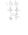
- FIG. 1 is a diagram illustrating a main part of a vehicle including a transmission.
- FIG. 2 is a diagram showing a main part of the hydraulic control circuit.
- FIG. 3 is a diagram showing an example of the shift map.
- FIG. 4A is a diagram illustrating an example of a normal target hydraulic pressure map.
- FIG. 4B is a diagram illustrating a comparative example of the target hydraulic pressure map.
- FIG. 5A is a diagram showing an example of a target hydraulic pressure map at the time of 1-2 shift.
- FIG. 5B is a diagram showing an example of a target hydraulic pressure map at the time of 2-1 shift.
- FIG. 6 is a flowchart illustrating an example of control performed by the controller.
- FIG. 7 is a diagram illustrating an example of a timing chart at the time of 1-2 shift.
- FIG. 8 is a diagram showing an example of a timing chart at the time of 2-1 shift.
- FIG. 1 is a diagram showing a main part of a vehicle including a transmission 100. As shown in FIG. The vehicle includes an engine 1, a torque converter 2, a variator 20, an auxiliary transmission mechanism 30, an axle portion 4, and drive wheels 5.
- the vehicle includes an engine 1, a torque converter 2, a variator 20, an auxiliary transmission mechanism 30, an axle portion 4, and drive wheels 5.
- Engine 1 constitutes a drive source for the vehicle.
- the torque converter 2 transmits power through the fluid.
- the variator 20 and the auxiliary transmission mechanism 30 output the input rotational speed at a rotational speed corresponding to the gear ratio.
- the axle portion 4 includes a reduction gear, a differential device, and a drive axle. The power of the engine 1 is transmitted to the drive wheels 5 through the torque converter 2, the variator 20, the auxiliary transmission mechanism 30 and the axle portion 4.
- the variator 20 is a continuously variable transmission mechanism, and includes a primary pulley 21, a secondary pulley 22, and a belt 23.
- PRI primary pulley
- SEC secondary pulley
- the PRI pulley 21 includes a fixed pulley 21a, a movable pulley 21b, and a PRI chamber 21c. In the PRI pulley 21, the PRI pressure is supplied to the PRI chamber 21c.
- the SEC pulley 22 includes a fixed pulley 22a, a movable pulley 22b, and an SEC chamber 22c. In the SEC pulley 22, the SEC pressure is supplied to the SEC chamber 22c.
- the belt 23 has a V-shaped sheave surface formed by a fixed pulley 21 a and a movable pulley 21 b of the PRI pulley 21, and a V-shape formed by a fixed pulley 22 a and a movable pulley 22 b of the SEC pulley 22. Wound around the sheave surface.
- the variator 20 constitutes a belt-type continuously variable transmission mechanism that changes speed by changing the winding diameter of the belt 23 by changing the groove widths of the PRI pulley 21 and the SEC pulley 22 respectively.
- the auxiliary transmission mechanism 30 is a stepped transmission mechanism and has two forward speeds and one reverse speed.
- the subtransmission mechanism 30 has a first speed and a second speed having a smaller gear ratio than the first speed as a forward gear.
- the auxiliary transmission mechanism 30 is provided in series on the output side of the variator 20 in the power transmission path from the engine 1 to the drive wheels 5.
- the subtransmission mechanism 30 may be directly connected to the variator 20 or may be indirectly connected to the variator 20 through another configuration such as a gear train.
- the sub-transmission mechanism 30 includes a planetary gear mechanism 31 and a plurality of frictional engagement elements including a low brake 32, a high clutch 33, and a Rev brake 34.
- the gear position of the subtransmission mechanism 30 is changed by adjusting the hydraulic pressure supplied to the plurality of friction engagement elements and changing the engagement / release state of the plurality of friction engagement elements.
- the gear position becomes the first speed. Further, when the high clutch 33 is engaged and the low brake 32 and the rev brake 34 are released, the gear position becomes the second speed. Further, when the Rev brake 34 is engaged and the Low brake 32 and the High clutch 33 are released, the shift speed is reverse.
- the gear ratio is changed in each of the variator 20 and the auxiliary transmission mechanism 30. For this reason, in the vehicle, a speed change according to a through speed ratio that is a speed ratio of the variator 20 and the subtransmission mechanism 30 is performed.
- the through speed ratio is a speed ratio obtained by multiplying the speed ratio of the variator 20 by the speed ratio of the auxiliary speed change mechanism 30.
- the variator 20 and the auxiliary transmission mechanism 30 constitute an automatic transmission mechanism 3.
- the variator 20 and the auxiliary transmission mechanism 30 may be configured as separate transmission mechanisms in structure.
- the vehicle further includes an oil pump 10, a hydraulic control circuit 11, and a controller 12.
- Oil pump 10 pumps oil.
- the oil pump 10 a mechanical oil pump that is driven by the power of the engine 1 can be used.
- the hydraulic control circuit 11 adjusts the pressure of the oil pumped from the oil pump 10, that is, the hydraulic pressure, and transmits it to each part of the variator 20 and the auxiliary transmission mechanism 30.
- FIG. 2 is a diagram showing a main part of the hydraulic control circuit 11.
- the hydraulic control circuit 11 includes a line pressure adjusting unit 11s, a PRI pressure adjusting unit 11a, and a SEC pressure adjusting unit 11b.
- the hydraulic control circuit 11 may be grasped as a configuration including the oil pump 10.
- the line pressure adjusting unit 11s generates and adjusts the line pressure PL based on the pressure of the oil pumped from the oil pump 10, that is, the hydraulic pressure.
- the line pressure PL is a hydraulic pressure that is the original pressure of the PRI pressure and the SEC pressure, and is set so that the belt 23 does not slip.
- the line pressure PL is detected by the line pressure sensor 61.
- the PRI pressure adjusting unit 11a adjusts the PRI pressure using the line pressure PL as a source pressure.
- the PRI pressure is detected by the PRI pressure sensor 62.
- the SEC pressure adjusting unit 11b adjusts the SEC pressure using the line pressure PL as a source pressure.
- the SEC pressure is detected by the SEC pressure sensor 63.
- a hydraulic regulator including a linear solenoid valve can be used as the line pressure adjusting unit 11s, the PRI pressure adjusting unit 11a, and the SEC pressure adjusting unit 11b.
- the controller 12 is an electronic control unit and controls the hydraulic control circuit 11. In addition to the line pressure sensor 61, the PRI pressure sensor 62, and the SEC pressure sensor 63, the controller 12 receives output signals from the rotation sensor 41, the rotation sensor 42, and the rotation sensor 43.
- the rotation sensor 41 is a variator input side rotation sensor for detecting the rotation speed on the input side of the variator 20.
- the rotation sensor 42 is a variator output side rotation sensor for detecting the rotation speed on the output side of the variator 20. Specifically, the rotation sensor 42 detects the rotation speed on the output side of the variator 20 and on the input side of the auxiliary transmission mechanism 30.
- the rotation sensor 43 is a sub transmission mechanism output side rotation sensor for detecting the rotation speed on the output side of the sub transmission mechanism 30.
- the rotation speed on the input side of the variator 20 is specifically the rotation speed of the input shaft of the variator 20.
- the rotational speed on the input side of the variator 20 may be, for example, the rotational speed at a position where the gear train is sandwiched between the variator 20 in the power transmission path described above. The same applies to the rotational speed on the output side of the variator 20 and the rotational speed on the output side of the auxiliary transmission mechanism 30.
- controller 12 also receives output signals from the accelerator opening sensor 44, the inhibitor switch 45, the engine rotation sensor 46, and the like.
- the accelerator opening sensor 44 detects an accelerator opening APO that represents the amount of operation of the accelerator pedal.
- the inhibitor switch 45 detects the position of the select lever.
- the engine rotation sensor 46 detects the rotation speed Ne of the engine 1.
- the controller 12 can detect the vehicle speed VSP based on the output signal of the rotation sensor 43.
- the controller 12 generates a shift control signal based on these signals, and outputs the generated shift control signal to the hydraulic control circuit 11.
- the hydraulic control circuit 11 controls the line pressure PL, PRI pressure, and SEC pressure based on the shift control signal from the controller 12 and switches the hydraulic path.
- the hydraulic pressure is transmitted from the hydraulic control circuit 11 to each part of the variator 20 and the auxiliary transmission mechanism 30 according to the shift control signal.
- the gear ratios of the variator 20 and the auxiliary transmission mechanism 30 are changed to the gear ratio corresponding to the gear shift control signal, that is, the target gear ratio.
- the transmission 100 is an automatic transmission, and in addition to the variator 20 and the auxiliary transmission mechanism 30, the hydraulic control circuit 11 and the controller 12 that control the transmission ratio in this way, the rotation sensor 41, the rotation sensor 42, the rotation sensor 43, And a line pressure sensor 61, a PRI pressure sensor 62, and a SEC pressure sensor 63.
- the transmission 100 may be configured to further include, for example, a pressure sensor that detects hydraulic pressure supplied to the plurality of frictional engagement elements of the auxiliary transmission mechanism 30.
- FIG. 3 is a diagram showing an example of a shift map.
- Shift of the transmission 100 is performed based on a shift map.
- the operating point of the transmission 100 is indicated according to the vehicle speed VSP and the rotational speed Npri.
- the rotational speed Npri is the rotational speed of the PRI pulley 21.
- Shift of the transmission 100 is performed according to a shift line selected according to the accelerator opening APO. For this reason, a shift line is set for each accelerator opening APO in the shift map.
- the transmission ratio of the transmission 100 that is, the through transmission ratio is indicated by the slope of a line connecting the operating point of the transmission 100 and the zero point of the transmission map.
- the transmission 100 uses the low speed mode lowest line obtained by maximizing the transmission ratio of the variator 20 and the low speed mode maximum obtained by minimizing the transmission ratio of the variator 20. Shifting with the High line can be performed.
- the transmission 100 uses the high-speed mode lowest line obtained by maximizing the transmission ratio of the variator 20 and the high-speed mode maximum obtained by minimizing the transmission ratio of the variator 20. Shifting with the High line can be performed.
- a mode switching shift line Lm for performing the shift of the auxiliary transmission mechanism 30 is further set.
- the mode switching shift line Lm is set to the low speed mode highest line.
- a region R1 indicates a region on the low vehicle speed VSP side with respect to the mode switching shift line Lm, and a region R2 indicates a region on the high vehicle speed VSP side with respect to the mode switching shift line Lm.
- the controller 12 starts the shift of the auxiliary transmission mechanism 30 when the operating point of the transmission 100 crosses the mode switching shift line Lm. Further, the controller 12 performs a coordinated shift in which the gear ratio of the variator 20 is changed in a direction opposite to the direction in which the gear ratio of the sub-transmission mechanism 30 changes with the shift of the sub-transmission mechanism 30.
- the controller 12 upshifts the shift speed of the subtransmission mechanism 30 from the first speed to the second speed when the operating point of the transmission 100 crosses the mode switching shift line Lm from the region R1 to the region R2. 1-2 shift is started. Further, in this case, the controller 12 specifically performs a coordinated shift in which the gear ratio of the variator 20 is changed in the direction in which the gear ratio increases, that is, the Low side.
- the cooperative shift may include performing a shift of the auxiliary transmission mechanism 30.
- the 2-1 shift for downshifting the gear position of the sub-transmission mechanism 30 from the second speed to the first speed is performed, for example, according to the driver's accelerator pedal operation or select lever operation.
- the variator 20 can perform a coordinated shift in which the gear ratio is changed in a direction in which the gear ratio decreases, that is, in the High side.
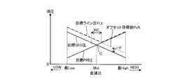
- the target hydraulic pressure map in which the target PRI pressure that is the target value of the PRI pressure, the target SEC pressure that is the target value of the SEC pressure, and the target line pressure PLt that is the target value of the line pressure PL will be described.
- FIG. 4A is a diagram illustrating an example of a target hydraulic pressure map in a normal state.
- FIG. 4B is a diagram illustrating a comparative example of the target hydraulic pressure map.
- the normal target hydraulic pressure map is a target hydraulic pressure map that is used when the auxiliary transmission mechanism 30 is not shifted.
- the comparative example of the target hydraulic pressure map corresponds to the technique described in the background art.
- the target PRI pressure and the target SEC pressure are set so that the magnitude relationship between the PRI pressure and the SEC pressure is switched according to the transmission ratio of the variator 20.
- the target PRI pressure and the target SEC pressure are set to be equal to each other at a Mid gear ratio that is a gear ratio between the lowest Low gear ratio and the highest High gear ratio.
- the Mid gear ratio is a gear ratio corresponding to the cross point C at which the target PRI pressure and the target SEC pressure are equal.
- the target PRI pressure and the target SEC pressure are larger than the target PRI pressure in the gear ratio range that is greater than or equal to the lowest gear ratio and less than the Mid gear ratio, that is, in the gear ratio range that is lower than the cross point C. Is set as follows.
- the target PRI pressure and the target SEC pressure are higher than the Mid gear ratio and less than or equal to the highest High gear ratio, that is, in the gear ratio range higher than the cross point C, the target PRI pressure is higher than the target SEC pressure. Set to be larger.
- the target line pressure PLt is set to the larger of the target PRI pressure and the target SEC pressure.
- the target line pressure PLt becomes the target SEC pressure in the gear ratio range lower than the cross point C. Further, in the speed ratio range higher than the cross point C, the target line pressure PLt becomes the target PRI pressure. At the Mid gear ratio, the target line pressure PLt becomes the target PRI pressure and the target SEC pressure.
- the target line pressure PLt is set to a value obtained by adding a predetermined offset amount ⁇ ′ that is a variable value to the higher one of the target PRI pressure and the target SEC pressure.
- the cross point region RC is a region where the absolute value of the deviation obtained by subtracting the target PRI pressure from the target SEC pressure is smaller than a predetermined deviation.
- the variator 20 when the coordinated shift is started in a state where the gear ratio of the variator 20 is included in the crosspoint region RC, that is, when the coordinated shift is started in the crosspoint region RC, the variator 20 is operated as follows. There is concern about the lack of hydraulic pressure.
- the target line pressure PLt decreases immediately before the gear ratio of the variator 20 deviates from the cross point region RC. Further, the target line pressure PLt increases after the gear ratio of the variator 20 deviates from the cross point region RC. For this reason, there is a concern that the actual line pressure PL undershoots the target line pressure PLt due to the target line pressure PLt changing from decreasing to increasing.
- the target line pressure PLt is set as follows at the time of 1-2 shift and 2-1 shift of the subtransmission mechanism 30.
- FIG. 5A is a diagram showing an example of a target hydraulic pressure map at the time of 1-2 shift.
- FIG. 5B is a diagram showing an example of a target hydraulic pressure map at the time of 2-1 shift.
- the target PRI pressure and the target SEC pressure are set in the same manner as in FIG. 4A.
- the target line pressure PLt has an offset target value Pof that is a value obtained by adding a positive offset amount ⁇ to one of the target PRI pressure and the target SEC pressure.
- the offset target value Pof is set within the gear ratio range.
- One of the target PRI pressure and the target SEC pressure is set to the higher one of the target PRI pressure and the target SEC pressure on the direction side in which the gear ratio of the variator 20 is changed by the cooperative shift.
- the gear ratio of the variator 20 changes to the Low side by the cooperative shift. Therefore, the higher one of the target PRI pressure and the target SEC pressure on the side where the speed ratio of the variator 20 changes is the target SEC pressure.
- the target line pressure PLt is set to the offset target value Pof within a speed ratio range in which the offset target value Pof obtained by adding the offset amount ⁇ to the target SEC pressure is higher than the target PRI pressure.
- the target line pressure PLt only increases and does not increase after decreasing.
- one of the target PRI pressure and the target SEC pressure is set to the target SEC pressure.
- the gear ratio of the variator 20 is changed to the High side by the coordinated shift. Therefore, the higher of the target PRI pressure and the target SEC pressure on the direction side where the speed ratio of the variator 20 changes is the target PRI pressure.
- the target line pressure PLt is set to the offset target value Pof within a speed ratio range in which the offset target value Pof obtained by adding the offset amount ⁇ to the target RPI pressure is higher than the target SEC pressure.
- the target line pressure PLt only increases and does not increase after decreasing.
- one of the target PRI pressure and the target SEC pressure is set to the target PRI pressure.
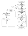
- controller 12 can repeatedly execute the processing shown in this flowchart every minute time.
- step S1 the controller 12 determines whether or not the auxiliary transmission mechanism 30 is in the first speed steady state. Such a determination can be made based on, for example, the shift map shown in FIG. If the determination is affirmative in step S1, the process proceeds to step S2.
- step S2 the controller 12 performs a prediction determination as to whether or not the 1-2 shift is performed.
- Such prediction determination can be performed, for example, by determining whether or not the target through speed ratio is below a predetermined value.
- the predetermined value can be set to a value slightly larger than the mode switching speed ratio that is the speed ratio corresponding to the mode switching speed line Lm, that is, the Low side.
- the prediction determination is performed by setting a prediction determination line along the mode switching shift line Lm in the region R ⁇ b> 1, and setting the prediction determination line from the region R ⁇ b> 1 to the region R ⁇ b> 2. It may be performed by determining whether or not it has crossed.
- step S7 the controller 12 permits the same pressure control to set the target line pressure PLt to the higher one of the target PRI pressure and the target SEC pressure.
- the same pressure control can be permitted by setting the target hydraulic pressure map to be referred to as the target hydraulic pressure map shown in FIG. 4A when setting the target line pressure PLt.
- step S2 determines whether the determination in step S2 is affirmative. If the determination in step S2 is affirmative, the process proceeds to step S3. In step S3, the controller 12 performs an increase setting of the target line pressure PLt.
- the increase setting of the target line pressure PLt can be performed by setting the target line pressure PLt based on the target hydraulic pressure map shown in FIG.
- the controller 12 can inhibit the same pressure control by increasing the target line pressure PLt.
- the increase setting of the target line pressure PLt may be performed, for example, by calculating the target line pressure PLt set in the target hydraulic pressure map shown in FIG. 5A each time based on the target hydraulic pressure map shown in FIG. 4A.
- step S4 the controller 12 determines whether the 1-2 shift has been started. Such a determination can be made by determining whether or not the operating point of the transmission 100 crosses the mode switching shift line Lm from the region R1 toward the region R2 in the shift map shown in FIG.
- step S4 If a negative determination is made in step S4, it is predicted that the 1-2 shift will be performed, but the 1-2 shift has not yet started, so the processing of this flowchart is temporarily ended.
- step S4 If the determination in step S4 is affirmative, the process proceeds to step S5.
- the transmission ratio of the auxiliary transmission mechanism 30 changes in an inertia phase, which is a shift stage in which the transmission ratio of the auxiliary transmission mechanism 30 actually changes.
- step S5 the controller 12 sets the target line pressure PLt to increase and increases the SEC pressure. That is, when the 1-2 shift is started, not only the increase setting of the target line pressure PLt is continued, but the SEC pressure is further increased.
- the increase of the SEC pressure is performed by increasing the target SEC pressure to a predetermined value.
- the predetermined value is set to a value at which the belt 23 does not slip in consideration of the amount of inertia torque caused by the change in the rotational speed of the SEC pulley 22 that occurs during the inertia phase of the auxiliary transmission mechanism 30.
- the predetermined value may be a variable value.
- the SEC pressure is increased based on the torque fluctuation generated by the input torque to the variator 20 according to the shift of the auxiliary transmission mechanism 30.
- step S6 the controller 12 determines whether the 1-2 shift has been completed. Such a determination can be made, for example, by determining whether or not the high clutch 33 is engaged and the low brake 32 is released.
- step S6 If a negative determination is made in step S6, since the 1-2 shift is being performed, the processing of this flowchart is temporarily ended. Then, while a negative determination is made in step S6 in the subsequent routine, the inertia phase is started, and the gear ratio of the auxiliary transmission mechanism 30 actually changes.
- step S6 If the determination in step S6 is affirmative, the process proceeds to step S7. That is, in this case, since the 1-2 shift has been completed, the controller 12 permits the same pressure control.
- step S1 determines whether or not the 1-2 shift is being performed.
- step S6 determines whether the determination in step S6 is negative in the previous routine. If the determination in step S6 is negative in the previous routine, an affirmative determination is made in step S8, and the process proceeds to step S5. If a negative determination is not made in step S6 in the previous routine, the 1-2 shift is not in progress, so a negative determination is made in step S8, and the process proceeds to step S9.
- step S9 the controller 12 determines whether or not the auxiliary transmission mechanism 30 is in the second speed steady state. If an affirmative determination is made in step S9, the process proceeds to step S7, where the same pressure control is permitted.
- step S9 the controller 12 determines that the 2-1 shift including the start of the 2-1 shift is in progress. In this case, the process proceeds to step S10.
- step S10 the controller 12 performs an increase setting of the target line pressure PLt.
- the target line pressure PLt is increased by setting the reference target hydraulic pressure map as a target hydraulic pressure map shown in FIG. 5B and setting the target line pressure PLt based on the target hydraulic pressure map shown in FIG. 5B. be able to. Also in this case, the controller 12 can prohibit the same pressure control by setting the target line pressure PLt to be increased.
- the increase setting of the target line pressure PLt may be performed, for example, by calculating the target line pressure PLt set in the target hydraulic pressure map shown in FIG. 5B each time based on the target hydraulic pressure map shown in FIG. 4A.
- step S10 the controller 12 further increases the SEC pressure. That is, when the 2-1 shift is started, not only the target line pressure PLt is increased but also the SEC pressure is increased. The increase in the SEC pressure is the same as that described in step S5.
- step S11 the controller 12 determines whether or not the 2-1 shift has been completed. Such a determination can be made, for example, by determining whether or not the high clutch 33 is released and the low brake 32 is engaged.
- step S11 If the determination in step S11 is negative, the process of this flowchart is temporarily terminated. In this case, the process of step S10 is continuously performed until an affirmative determination is made in step S11 in the subsequent routine. If it is affirmation determination by step S11, a process will progress to step S7 and same pressure control will be permitted.
- FIG. 7 is a diagram showing an example of a timing chart at the time of 1-2 shift.
- Timing T11 is a timing at which it is determined that a 1-2 shift will be performed. For this reason, the target line pressure PLt is set to increase from the timing T11, and the same pressure control is prohibited.
- Timing T12 is at the time of shifting start determination of 1-2 shifting. For this reason, the SEC pressure is increased from the timing T12.
- the increase of the SEC pressure is maintained until the target SEC pressure based on the target hydraulic pressure map shown in FIG. 5A becomes larger than the target SEC pressure increased to a predetermined value by increasing the SEC pressure.
- the larger of the target SEC pressure based on the target hydraulic pressure map shown in FIG. 5A and the target SEC pressure increased to a predetermined value by increasing the SEC pressure is used as the target SEC pressure.
- the reference target hydraulic pressure map itself is the target hydraulic pressure map shown in FIG. 5A at timing T11. Therefore, even in this case, the prohibition of the same pressure control itself is effective.
- the inertia phase ends at timing T14, and the 1-2 shift ends at timing T15. For this reason, the same pressure control is permitted from the timing T15.
- the target PRI pressure, the target SEC pressure, and the target line pressure PLt are set based on FIG. 5A.
- the target SEC pressure is set based on FIG. 5A when the increase in the SEC pressure is not maintained.
- the target PRI pressure decreases, and the target line pressure PLt and the target SEC pressure increase. Therefore, even if the coordinated shift is started in the cross point region RC and the gear ratio of the variator 20 changes to the low side, the target line pressure PLt and the target SEC pressure do not turn from a decrease to an increase.
- FIG. 8 is a diagram showing an example of a timing chart at the time of 2-1 shift.
- FIG. 8 shows only actual values for each parameter.
- Timing T21 is a time when the sub-transmission mechanism 30 determines to start the 2-1 shift.
- the target line pressure PLt is set to increase, and the same pressure control is prohibited.
- the line pressure PL increases immediately after the timing T21.
- the SEC pressure is also increased.
- the SEC pressure also increases immediately after timing T21.
- the target line pressure PLt is set to increase and the SEC pressure is increased at the start of shift determination, and these are performed before the inertia phase of the auxiliary transmission mechanism 30 starts.
- the target SEC pressure is set to be larger than the target SEC pressure set in the target hydraulic pressure map shown in FIG. Therefore, in this example, the SEC pressure increases even when the inertia phase is started and the gear ratio of the variator 20 is changed to the High side.
- the line pressure PL is increased so that the increase of the SEC pressure can be maintained separately from the increase setting of the target line pressure PLt.
- the line pressure PL is increased by setting the target line pressure PLt to be larger than the target SEC pressure.
- the target line pressure PLt is also set larger than the target line pressure PLt set in the target hydraulic pressure map shown in FIG. 5B. Therefore, in this example, the line pressure PL is constant even when the inertia phase is started and the gear ratio of the variator 20 starts to change to the High side. The line pressure PL is increased prior to the SEC pressure.
- the increase of the SEC pressure is maintained until the target SEC pressure based on the target hydraulic pressure map shown in FIG. 5B becomes larger than the target SEC pressure increased to a predetermined value by increasing the SEC pressure.
- the larger of the target SEC pressure based on the target hydraulic pressure map shown in FIG. 5B and the target SEC pressure increased to a predetermined value by increasing the SEC pressure is used as the target SEC pressure.
- the reference target hydraulic pressure map itself is the target hydraulic pressure map shown in FIG. 5B at timing T21. Therefore, even in this case, the prohibition of the same pressure control itself is effective.
- the increase of the SEC pressure and the increase of the line pressure PL can be performed so that the decrease of the SEC pressure does not occur.
- the inertia phase starts immediately after timing T21. After the start of the inertia phase, the transmission ratio of the subtransmission mechanism 30 increases and the transmission ratio of the variator 20 decreases. In this example, the speed ratio of the variator 20 is reduced so that the through speed ratio does not become too large due to the 2-1 speed change of the auxiliary speed change mechanism 30.
- the coordinated speed change is not limited to the case where the through speed change ratio is set to the target through speed change ratio, and the speed change ratio of the variator 20 is changed as shown in this example as the sub speed change mechanism 30 is changed. This includes cases where
- the SEC pressure is increased or the line pressure PL is increased.
- the target PRI pressure and the target SEC are increased.
- the pressure and the target line pressure PLt are set based on the target hydraulic pressure map of FIG. 5B.
- the target line pressure PLt and the target PRI pressure turn from decreasing to increasing. There is nothing.
- the transmission 100 includes a variator 20, an auxiliary transmission mechanism 30, a line pressure adjustment unit 11s, a PRI pressure adjustment unit 11a, a SEC pressure adjustment unit 11b, and a controller 12.
- the controller 12 is provided in the transmission 100 as a shift control unit that performs a coordinated shift.
- the controller 12 is provided in the transmission 100 as a setting unit that sets the target line pressure PLt.
- the controller 12 as the setting unit is a value obtained by adding a positive offset amount ⁇ to one of the target PRI pressure and the target SEC pressure at least during the inertia phase in the auxiliary transmission mechanism 30 when coordinated shift is performed.
- the target line pressure PLt is set to the offset target value Pof in the speed ratio range in which the offset target value Pof is higher than the other.
- the controller 12 as the setting unit sets one of the target PRI pressure and the target SEC pressure as the target SEC pressure when the variator 20 is downshifted by the coordinated shift, and when the variator 20 is upshifted by the coordinated shift. Is the target PRI pressure.
- the target line pressure PLt is set to the offset target value Pof as described above, when the cooperative shift is started in the crosspoint region RC and the transmission ratio of the variator 20 is changed.
- the target line pressure PLt can be increased according to the change. That is, it is possible to prevent the target line pressure PLt from changing from a decrease to an increase.
- the controller 12 as a setting unit sets the target line pressure PLt before the start of the inertia phase in the auxiliary transmission mechanism 30.
- the line pressure PL falls below the target line pressure PLt at the start of the inertia phase due to a delay in the response of the hydraulic pressure supply. Can be prevented or suppressed. That is, it is possible to prevent or suppress a situation in which insufficient hydraulic pressure occurs in the variator 20 at the time of coordinated shift due to a delay in response of the hydraulic pressure supply.
- slippage may occur in the belt 23 due to torque fluctuations generated by the input torque to the variator 20 according to the shift of the auxiliary transmission mechanism 30. Further, if the line pressure PL and the SEC pressure are increased at the same timing, the fluctuation range of the hydraulic pressure becomes large, and an unintended speed ratio change may occur.
- the controller 12 as the shift control unit increases the SEC pressure when determining the shift start of the sub-transmission mechanism 30. . Further, the controller 12 as the setting unit sets the target line pressure PLt to the offset target value Pof before determining the shift start of the auxiliary transmission mechanism 30.
- the SEC pressure can be increased before the start of the inertia phase. Therefore, the slip of the belt 23 is caused by the torque fluctuation generated according to the shift of the auxiliary transmission mechanism 30 in the inertia phase. Can be prevented or suppressed. Further, since the line pressure PL, which is the original pressure of the SEC pressure, is increased prior to the SEC pressure, it is possible to prevent or suppress the occurrence of an unintended change in the gear ratio.
- the upshift of the subtransmission mechanism 30 is performed in a driving state where there is almost no driver's accelerator pedal operation. For this reason, when the subtransmission mechanism 30 is upshifted, if an unintended change in the gear ratio occurs, the driver feels uncomfortable.
- the downshift of the auxiliary transmission mechanism 30 is performed when the driver depresses the accelerator pedal or operates the select lever. For this reason, in this case, it is necessary to satisfy the driver's acceleration request by performing a speed change as quickly as possible. In this case, since the driver's acceleration request operation is involved, even if an unintended change in the gear ratio occurs, it is difficult for the driver to perceive a phenomenon that gives a sense of incongruity.
- the controller 12 serving as a shift control unit increases the SEC pressure when determining the shift start of the sub-transmission mechanism 30. . Further, the controller 12 as the setting unit sets the target line pressure PLt to the offset target value Pof when determining the shift start of the auxiliary transmission mechanism 30.
- the shift of the auxiliary transmission mechanism 30 is a downshift
- the line pressure PL and the SEC pressure are not increased in order for a certain period of time, and the shift start determination is performed. Since both are increased, the shift response can be enhanced to satisfy the acceleration request.
- the auxiliary transmission mechanism 30 may have, for example, three or more forward speeds.
- the controller 12 When coordinated shift is performed such as at the start of an inertia phase, if the gear ratio of the variator 20 is not included in the crosspoint region RC, the controller 12 as the setting unit does not set the target line pressure PLt to the offset target value Pof. Good.
- the controller 12 as the setting unit may set the target line pressure PLt to the offset target value Pof when the gear ratio of the variator 20 is included in the cross point region RC when the coordinated shift is performed.
- the controller 12 can set the target line pressure PLt based on the target hydraulic pressure map shown in FIG. 4A.
- the drive source is the engine 1
- the drive source may be, for example, a motor, a combination of an engine and a motor.
Landscapes
- Engineering & Computer Science (AREA)
- General Engineering & Computer Science (AREA)
- Mechanical Engineering (AREA)
- Control Of Transmission Device (AREA)
Abstract
Description
Claims (5)
- プライマリ圧が供給されるプライマリプーリと、セカンダリ圧が供給されるセカンダリプーリと、前記プライマリプーリ及び前記セカンダリプーリに巻き掛けられたベルトと、を有し、車両の駆動源から駆動輪に動力を伝達する動力伝達経路に設けられる無段変速機構と、
前記動力伝達経路に前記無段変速機構と直列に設けられる有段変速機構と、
ライン圧を調整するライン圧調整部と、
前記ライン圧を元圧にして前記プライマリ圧の調整を行うプライマリ圧調整部と、
前記ライン圧を元圧にして前記セカンダリ圧の調整を行うセカンダリ圧調整部と、
前記有段変速機構の変速に伴い、前記有段変速機構の変速比が変化する方向と反対の方向に前記無段変速機構の変速比を変化させる協調変速を行う変速制御部と、
前記ライン圧の目標値を設定する設定部と、
を備え、
前記設定部は、
前記協調変速が行われる場合に、少なくとも前記有段変速機構におけるイナーシャフェーズの間、前記プライマリ圧の目標値及び前記セカンダリ圧の目標値のうち一方の目標値に正のオフセット量を加算して得られる値であるオフセット目標値が他方の目標値よりも高くなる変速比範囲で、前記ライン圧の目標値を前記オフセット目標値に設定するに際して、
前記協調変速で前記無段変速機構がダウンシフトする場合、前記一方の目標値を前記セカンダリ圧の目標値に設定し、前記協調変速で前記無段変速機構がアップシフトする場合、前記一方の目標値を前記プライマリ圧の目標値に設定する、
変速機。 - 請求項1に記載の変速機であって、
前記設定部は、前記有段変速機構におけるイナーシャフェーズの開始前に、前記ライン圧の目標値を設定する、
変速機。 - 請求項2に記載の変速機であって、
前記有段変速機構の変速がアップシフトである場合に、
前記変速制御部は、前記有段変速機構の変速に応じて前記無段変速機構への入力トルクで発生するトルク変動に基づき、前記有段変速機構の変速開始判定時に前記セカンダリ圧を増大させ、
前記設定部は、前記有段変速機構の変速開始判定前に前記ライン圧の目標値を前記オフセット目標値に設定する、
変速機。 - 請求項2又は3に記載の変速機であって、
前記有段変速機構の変速がダウンシフトである場合に、
前記変速制御部は、前記有段変速機構の変速に応じて前記無段変速機構への入力トルクで発生するトルク変動に基づき、前記有段変速機構の変速開始判定時に前記セカンダリ圧を増大させ、
前記設定部は、前記有段変速機構の変速開始判定時に前記ライン圧の目標値を前記オフセット目標値に設定する、
変速機。 - プライマリ圧が供給されるプライマリプーリとセカンダリ圧が供給されるセカンダリプーリと前記プライマリプーリ及び前記セカンダリプーリに巻き掛けられたベルトとを有し車両の駆動源から駆動輪に動力を伝達する動力伝達経路に設けられる無段変速機構と、前記動力伝達経路に前記無段変速機構と直列に設けられる有段変速機構と、ライン圧を調整するライン圧調整部と、前記ライン圧を元圧にして前記プライマリ圧の調整を行うプライマリ圧調整部と、前記ライン圧を元圧にして前記セカンダリ圧の調整を行うセカンダリ圧調整部と、を備える変速機の制御方法であって、
前記有段変速機構の変速に伴い、前記有段変速機構の変速比が変化する方向と反対の方向に前記無段変速機構の変速比を変化させる協調変速を行うことと、
前記ライン圧の目標値を設定するにあたり、
前記協調変速が行われる場合に、少なくとも前記有段変速機構におけるイナーシャフェーズの間、前記プライマリ圧の目標値及び前記セカンダリ圧の目標値のうち一方の目標値に正のオフセット量を加算して得られる値であるオフセット目標値が他方の目標値よりも高くなる変速比範囲で、前記ライン圧の目標値を前記オフセット目標値に設定するに際して、
前記協調変速で前記無段変速機構がダウンシフトする場合、前記一方の目標値を前記セカンダリ圧の目標値に設定し、前記協調変速で前記無段変速機構がアップシフトする場合、前記一方の目標値を前記プライマリ圧の目標値に設定すること、
を含む変速機の制御方法。
Priority Applications (5)
| Application Number | Priority Date | Filing Date | Title |
|---|---|---|---|
| JP2017525220A JP6442056B2 (ja) | 2015-06-23 | 2016-06-13 | 変速機及び変速機の制御方法 |
| KR1020187001087A KR101992069B1 (ko) | 2015-06-23 | 2016-06-13 | 변속기 및 변속기의 제어 방법 |
| CN201680036743.1A CN107709841B (zh) | 2015-06-23 | 2016-06-13 | 变速器及变速器的控制方法 |
| US15/738,904 US10400893B2 (en) | 2015-06-23 | 2016-06-13 | Transmission and control method for transmission |
| EP16814209.9A EP3315823A4 (en) | 2015-06-23 | 2016-06-13 | Transmission and transmission control method |
Applications Claiming Priority (2)
| Application Number | Priority Date | Filing Date | Title |
|---|---|---|---|
| JP2015-125529 | 2015-06-23 | ||
| JP2015125529 | 2015-06-23 |
Publications (1)
| Publication Number | Publication Date |
|---|---|
| WO2016208438A1 true WO2016208438A1 (ja) | 2016-12-29 |
Family
ID=57585747
Family Applications (1)
| Application Number | Title | Priority Date | Filing Date |
|---|---|---|---|
| PCT/JP2016/067531 WO2016208438A1 (ja) | 2015-06-23 | 2016-06-13 | 変速機及び変速機の制御方法 |
Country Status (6)
| Country | Link |
|---|---|
| US (1) | US10400893B2 (ja) |
| EP (1) | EP3315823A4 (ja) |
| JP (1) | JP6442056B2 (ja) |
| KR (1) | KR101992069B1 (ja) |
| CN (1) | CN107709841B (ja) |
| WO (1) | WO2016208438A1 (ja) |
Cited By (1)
| Publication number | Priority date | Publication date | Assignee | Title |
|---|---|---|---|---|
| US20230053741A1 (en) * | 2021-08-18 | 2023-02-23 | Hyundai Motor Company | Hydraulic pressure control method for a vehicle transmission |
Families Citing this family (3)
| Publication number | Priority date | Publication date | Assignee | Title |
|---|---|---|---|---|
| JP6502489B2 (ja) * | 2015-05-22 | 2019-04-17 | ジヤトコ株式会社 | 車両の制御装置、及びその制御方法 |
| JP6437125B2 (ja) * | 2015-09-09 | 2018-12-12 | ジヤトコ株式会社 | 車両用無段変速機の油圧制御装置および油圧制御方法 |
| CN116964351A (zh) * | 2021-02-22 | 2023-10-27 | 加特可株式会社 | 传感器的配置结构 |
Citations (3)
| Publication number | Priority date | Publication date | Assignee | Title |
|---|---|---|---|---|
| JP2011208680A (ja) * | 2010-03-29 | 2011-10-20 | Jatco Ltd | 無段変速機及びその制御方法 |
| JP2012197819A (ja) * | 2011-03-18 | 2012-10-18 | Toyota Motor Corp | 車両用無段変速機の制御装置 |
| JP5736508B2 (ja) * | 2012-10-15 | 2015-06-17 | ジヤトコ株式会社 | 無段変速機及びその制御方法 |
Family Cites Families (9)
| Publication number | Priority date | Publication date | Assignee | Title |
|---|---|---|---|---|
| KR101216843B1 (ko) * | 2005-07-27 | 2013-01-09 | 로베르트 보쉬 게엠베하 | 무단 변속기 작동 방법 |
| JP2010043676A (ja) * | 2008-08-11 | 2010-02-25 | Toyota Motor Corp | 無段変速機および無段変速機の制御方法 |
| JP4660583B2 (ja) * | 2008-09-25 | 2011-03-30 | ジヤトコ株式会社 | 無段変速機及びその変速制御方法 |
| JP5256253B2 (ja) * | 2009-07-17 | 2013-08-07 | 日産自動車株式会社 | 自動変速機 |
| JP4847567B2 (ja) * | 2009-08-26 | 2011-12-28 | ジヤトコ株式会社 | 無段変速機及びその制御方法 |
| CN103597252B (zh) * | 2011-06-14 | 2015-11-25 | 加特可株式会社 | 滑行停止车辆及其控制方法 |
| JP5740336B2 (ja) * | 2012-03-28 | 2015-06-24 | ジヤトコ株式会社 | 無段変速機の変速制御装置 |
| KR101586162B1 (ko) * | 2012-03-28 | 2016-01-15 | 쟈트코 가부시키가이샤 | 무단 변속기 및 그 유압 제어 방법 |
| CN104246315B (zh) * | 2012-04-02 | 2017-11-24 | 加特可株式会社 | 无级变速器的控制装置 |
-
2016
- 2016-06-13 WO PCT/JP2016/067531 patent/WO2016208438A1/ja active Application Filing
- 2016-06-13 EP EP16814209.9A patent/EP3315823A4/en not_active Withdrawn
- 2016-06-13 JP JP2017525220A patent/JP6442056B2/ja active Active
- 2016-06-13 KR KR1020187001087A patent/KR101992069B1/ko active IP Right Grant
- 2016-06-13 US US15/738,904 patent/US10400893B2/en active Active
- 2016-06-13 CN CN201680036743.1A patent/CN107709841B/zh active Active
Patent Citations (3)
| Publication number | Priority date | Publication date | Assignee | Title |
|---|---|---|---|---|
| JP2011208680A (ja) * | 2010-03-29 | 2011-10-20 | Jatco Ltd | 無段変速機及びその制御方法 |
| JP2012197819A (ja) * | 2011-03-18 | 2012-10-18 | Toyota Motor Corp | 車両用無段変速機の制御装置 |
| JP5736508B2 (ja) * | 2012-10-15 | 2015-06-17 | ジヤトコ株式会社 | 無段変速機及びその制御方法 |
Non-Patent Citations (1)
| Title |
|---|
| See also references of EP3315823A4 * |
Cited By (2)
| Publication number | Priority date | Publication date | Assignee | Title |
|---|---|---|---|---|
| US20230053741A1 (en) * | 2021-08-18 | 2023-02-23 | Hyundai Motor Company | Hydraulic pressure control method for a vehicle transmission |
| US12007018B2 (en) * | 2021-08-18 | 2024-06-11 | Hyundai Motor Company | Hydraulic pressure control method for a vehicle transmission |
Also Published As
| Publication number | Publication date |
|---|---|
| US10400893B2 (en) | 2019-09-03 |
| CN107709841A (zh) | 2018-02-16 |
| EP3315823A1 (en) | 2018-05-02 |
| EP3315823A4 (en) | 2018-07-25 |
| JP6442056B2 (ja) | 2018-12-19 |
| US20180180178A1 (en) | 2018-06-28 |
| KR101992069B1 (ko) | 2019-06-21 |
| CN107709841B (zh) | 2019-08-02 |
| JPWO2016208438A1 (ja) | 2018-04-05 |
| KR20180018709A (ko) | 2018-02-21 |
Similar Documents
| Publication | Publication Date | Title |
|---|---|---|
| KR101647513B1 (ko) | 무단 변속기 및 그 제어 방법 | |
| US8666616B2 (en) | Continuously variable transmission and control method therefore | |
| US9964207B2 (en) | Continuously variable transmission and method for controlling the same | |
| US10228055B2 (en) | Continuously variable transmission and method for controlling the same | |
| JP6442056B2 (ja) | 変速機及び変速機の制御方法 | |
| WO2014050453A1 (ja) | 無段変速機及びその制御方法 | |
| WO2015053073A1 (ja) | 副変速機付き無段変速機の制御装置 | |
| US9416873B2 (en) | Continuously variable transmission and control method therefor | |
| JP5379056B2 (ja) | 無段変速機及びその制御方法 | |
| US11365805B2 (en) | Control device for vehicle and control method for vehicle | |
| JP6644413B2 (ja) | 無段変速機の制御装置 | |
| JP6576275B2 (ja) | 自動変速機の制御装置 | |
| JP5977271B2 (ja) | 無段変速機及びその制御方法 | |
| JP6412647B2 (ja) | 変速機及び変速機の制御方法 | |
| WO2022176673A1 (ja) | 無段変速機、無段変速機の制御方法、及びプログラム | |
| JP5993391B2 (ja) | 変速機及びその制御方法 | |
| JP5292494B2 (ja) | 無段変速機 | |
| WO2019049583A1 (ja) | 無段変速機の制御装置及び無段変速機の制御方法 |
Legal Events
| Date | Code | Title | Description |
|---|---|---|---|
| 121 | Ep: the epo has been informed by wipo that ep was designated in this application |
Ref document number: 16814209 Country of ref document: EP Kind code of ref document: A1 |
|
| ENP | Entry into the national phase |
Ref document number: 2017525220 Country of ref document: JP Kind code of ref document: A |
|
| WWE | Wipo information: entry into national phase |
Ref document number: 15738904 Country of ref document: US |
|
| NENP | Non-entry into the national phase |
Ref country code: DE |
|
| ENP | Entry into the national phase |
Ref document number: 20187001087 Country of ref document: KR Kind code of ref document: A |
|
| WWE | Wipo information: entry into national phase |
Ref document number: 2016814209 Country of ref document: EP |