WO2016208259A1 - 管理装置、無線装置、通信システム、管理方法 - Google Patents
管理装置、無線装置、通信システム、管理方法 Download PDFInfo
- Publication number
- WO2016208259A1 WO2016208259A1 PCT/JP2016/062320 JP2016062320W WO2016208259A1 WO 2016208259 A1 WO2016208259 A1 WO 2016208259A1 JP 2016062320 W JP2016062320 W JP 2016062320W WO 2016208259 A1 WO2016208259 A1 WO 2016208259A1
- Authority
- WO
- WIPO (PCT)
- Prior art keywords
- wireless device
- data
- state
- unit
- management
- Prior art date
- Legal status (The legal status is an assumption and is not a legal conclusion. Google has not performed a legal analysis and makes no representation as to the accuracy of the status listed.)
- Ceased
Links
Images











Classifications
-
- G—PHYSICS
- G06—COMPUTING OR CALCULATING; COUNTING
- G06F—ELECTRIC DIGITAL DATA PROCESSING
- G06F13/00—Interconnection of, or transfer of information or other signals between, memories, input/output devices or central processing units
-
- H—ELECTRICITY
- H04—ELECTRIC COMMUNICATION TECHNIQUE
- H04W—WIRELESS COMMUNICATION NETWORKS
- H04W8/00—Network data management
- H04W8/22—Processing or transfer of terminal data, e.g. status or physical capabilities
- H04W8/24—Transfer of terminal data
-
- H—ELECTRICITY
- H04—ELECTRIC COMMUNICATION TECHNIQUE
- H04W—WIRELESS COMMUNICATION NETWORKS
- H04W84/00—Network topologies
- H04W84/02—Hierarchically pre-organised networks, e.g. paging networks, cellular networks, WLAN [Wireless Local Area Network] or WLL [Wireless Local Loop]
- H04W84/04—Large scale networks; Deep hierarchical networks
- H04W84/08—Trunked mobile radio systems
Definitions
- the present invention relates to communication technology, and more particularly to a management device, a wireless device, a communication system, and a management method for transmitting update data.
- the base station apparatus transmits a request to the electronic device to be updated. Furthermore, after transmitting the request, the base station apparatus transmits the update content to the electronic device that has returned from the sleep state (for example, Patent Document 1).
- the updateable state is a state in which the update content can be received and a process for reflecting the received update content can be executed.
- One example is the return from the sleep state, but various other states are also included. Therefore, it is desirable to efficiently execute update processing such as update according to various states of the wireless device.
- the present invention has been made in view of such circumstances, and an object thereof is to provide a technique for efficiently executing update processing for a wireless device in accordance with the state of the wireless device.
- a management device includes a receiving unit that receives a status notification regarding the status of the wireless device from each of a plurality of wireless devices, and a status notification received by the receiving unit. And an adjustment unit that adjusts the priority order of each of the plurality of wireless devices, and an order according to the priority order adjusted by the adjustment unit for each of the plurality of wireless devices to update the wireless device.
- a transmission unit that transmits the update data.
- Another aspect of the present invention is a wireless device.
- This device includes a state management unit that acquires a state of a wireless device, a plurality of states that can be acquired by the state management unit, and a storage unit that stores a state identification number for identifying each state in association with each other
- the communication unit that receives the update data of the wireless device or the update data update notification, and when the communication unit receives the update data update notification, the state management unit acquires the status of the wireless device and updates the update data.
- a status transmission unit is provided that performs status notification for transmitting the status identification number of the acquired information.
- Still another aspect of the present invention is a communication system.
- the communication system includes a plurality of wireless devices and a management device that manages update data for updating each of the plurality of wireless devices.
- the management device adjusts the priority order for each of the plurality of wireless devices based on the status notification, and determines the order according to the priority order. Update data is transmitted to each of the plurality of wireless devices.
- Still another aspect of the present invention is also a communication system.
- the communication system includes a plurality of wireless devices, a trunking device that controls communication states of the plurality of wireless devices, and a management device that manages update data for updating each of the plurality of wireless devices.
- the management device receives the status notification regarding the status of each of the plurality of wireless devices from the trunking device, the management device adjusts the priority order for each of the plurality of wireless devices based on the status notification, and performs the order according to the priority order. Update data is transmitted to each of the plurality of wireless devices via the trunking device.
- Still another aspect of the present invention is a management method.
- the method includes a step of receiving a status notification regarding the status of the wireless device from each of the plurality of wireless devices, a step of adjusting a priority order for each of the plurality of wireless devices based on the received status notification, Transmitting update data for updating the wireless device to each of the plurality of wireless devices in an order according to the adjusted priority order.
- the update process for the wireless device can be efficiently executed in accordance with the state of the wireless device.
- FIGS. 9A and 9B are diagrams showing the data structure of the table stored in the storage unit of FIG. It is a flowchart which shows the update procedure by the management apparatus of FIG. It is a sequence diagram which shows the data rewriting procedure by the communication system which concerns on Example 2 of this invention. It is a figure which shows the data structure of the table memorize
- FIGS. 16A and 16B are diagrams illustrating the data structure of the table stored in the storage unit according to the fourth embodiment of the present invention. It is a sequence diagram which shows the data rewriting procedure by the communication system which concerns on Example 5 of this invention.
- FIGS. 18A and 18B are diagrams illustrating the data structure of the table stored in the storage unit according to the fifth embodiment of the present invention. It is a sequence diagram which shows the data rewriting procedure by the communication system which concerns on Example 6 of this invention. It is a figure which shows the data structure of the table memorize
- FIG. 26 is a sequence diagram showing a data rewrite procedure by the communication system of FIG. 25.
- FIGS. 29A to 29C are diagrams illustrating the data structures of the tables stored in the storage unit according to the ninth embodiment of the present invention.
- Embodiment 1 of the present invention relates to a communication system that updates a program, data, and the like stored in a wireless device via a wireless line.
- business radio is used as the radio line.
- the business radio performs voice communication on a predetermined radio CH.
- An example of voice communication is PTT (Push to Talk).
- PTT Push to Talk
- a user presses a button during a conversation and releases the button at the end of the conversation.
- a group can be formed by a plurality of radio apparatuses.
- the business radio base station apparatus allocates an uplink channel and a downlink channel to a group. Under such circumstances, one wireless device in the group transmits a signal on the uplink channel, and another wireless device in the group receives a signal on the downlink channel.
- the wireless device In the wireless device, information on usable uplink and downlink channels, registration site information, ID (Identification) information, and various other information relating to other settings are written. These pieces of information are also called setting data and wireless device data, and are created for each wireless device.
- This wireless device data it has been the mainstream to connect a wired cable to the wireless device.
- By using Over The Air Programming (OTAP) it becomes possible to update via a wireless line.
- the update order is set in advance.
- the wireless device may update the wireless device data to be updated (hereinafter referred to as “updated data”). (They may be used indistinguishably).
- the priority order for each wireless device to be updated is dynamically set according to the state of the wireless device such as the transition to the sleep state when the power is turned off, the return from the sleep state when the power is turned on, or the start of charging. It is preferred that
- the wireless device is connected to the base station device via a wireless line, and the base station device is connected to the management device via a wired line.
- the management device controls transmission of update data.
- the wireless device notifies the management device that there is a high possibility that update data can be received from now on, that there is a high possibility that update data cannot be received from now on, and that update data cannot be received from now on. For example, when the wireless device shifts to a sleep state due to power-off or starts charging, the wireless device notifies the fact that there is a high possibility that update data can be received because communication will not be performed. Also, during the operation of some kind of radio device such as the start of transmission by a call, it is notified that the update data cannot be received immediately.
- the management device manages an ID for identifying each wireless device (hereinafter referred to as “Unit ID”) and the order in which update processing is executed, and adjusts the priority when receiving a notification from the wireless device.
- Update process is executed.
- the data update can be said to be a data rewrite.
- the update target wireless device may be notified from the management device that data rewriting will start soon.
- FIG. 1 shows a configuration of a communication system 100 according to the first embodiment of the present invention.
- the communication system 100 includes a first radio apparatus 10 a, a second radio apparatus 10 b, a third radio apparatus 10 c, a base station apparatus 12, a network 14, and a management apparatus 16 that are collectively referred to as the radio apparatus 10.
- the number of wireless devices 10 included in the communication system 100 is not limited to “3”.
- the wireless device 10 is a device capable of performing communication by commercial wireless. Since publicly known technology may be used for commercial radio, description thereof is omitted here.
- the first wireless device 10a corresponds to a transmission side for voice communication by commercial radio
- the second radio device 10b corresponds to a reception side for voice communication by commercial radio.
- the base station apparatus 12 is a base station apparatus compatible with a commercial radio system.
- the base station device 12 is connected to the wireless device 10 by commercial radio at one end side and is connected to the network 14 at the other end side.
- the network 14 is a network for executing communication via a wired line, and is, for example, an IP (Internet Protocol) network. Note that another base station device 12 different from the base station device 12 may be connected to the network 14.
- the management device 16 is connected to the network 14. The management device 16 can also communicate with the wireless device 10 via the network 14 and the base station device 12.
- the management device 16 manages update data for updating each of the plurality of wireless devices 10.
- the management device 16 transmits a notification (hereinafter referred to as “data rewrite notification”) for notifying that the update data will be transmitted soon to the wireless device 10 to be updated.
- data rewrite notification a notification for notifying that the update data will be transmitted soon to the wireless device 10 to be updated.
- state notification a notification indicating the state of the wireless device 10 (hereinafter referred to as “state notification”) to the management device 16.
- the status notification may be transmitted periodically.
- the management device 16 When receiving the status notification from each of the plurality of wireless devices 10, the management device 16 adjusts the priority order of each of the plurality of wireless devices 10 based on the status notification. Here, it is shown that the wireless device 10 with higher priority is more likely to receive update data.
- the management device 16 transmits the update data to each of the plurality of wireless devices 10 in the order according to the priority order. More specifically, the management device 16 transmits update data in order from the wireless device 10 with the higher priority.
- the wireless device 10 that has received the update data from the management device 16 executes update processing.
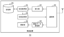
- FIG. 2 shows the configuration of the wireless device 10.
- the wireless device 10 includes a communication unit 20, a reception unit 22, a state management unit 24, a storage unit 26, a state transmission unit 28, an update data reception unit 30, and an update unit 32.
- the communication unit 20 executes communication for business use with a base station device 12 (not shown). For example, the communication unit 20 performs voice communication with another wireless device 10 via the base station device 12. Further, the communication unit 20 performs data communication with the management device 16 via the base station device 12 and the management device 16.
- the data communication here corresponds to transmission / reception of information until update data is received.
- the accepting unit 22 receives a data rewrite notification from the management device 16 via the communication unit 20.
- the reception unit 22 notifies the state management unit 24 that the data rewrite notification has been received, whereby the wireless device 10 transitions to a data standby state.
- the state management unit 24 starts the operation when the state transitions to the data standby state, and acquires the state of the wireless device 10.
- a state in which the wireless device 10 is not used from now on such as transition to a sleep state due to power-off and start of charging
- the transition to the sleep state is referred to as “power off”
- the return from the sleep state is similarly referred to as “power on”.
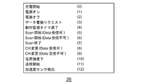
- the storage unit 26 stores a correspondence relationship between a plurality of states that can be acquired by the state management unit 24 and “state identification No.” for identifying each state as a table.
- FIG. 3 shows the data structure of the table stored in the storage unit 26.
- the state management unit 24 refers to the storage unit 26 to identify the “state identification number” corresponding to the acquired state. Note that the state management unit 24 does not specify “state identification No.” when it is not in the data standby state. Such a data standby state is not released until the reception of update data is completed.
- the state transmission unit 28 inputs “state identification No.” indicating the state of the wireless device 10 from the state management unit 24.
- the state transmission unit 28 generates a state notification based on the “state identification No.”.
- the status notification is either a state where there is a high possibility that update data can be received from now on, a state where there is a high possibility that update data cannot be received from now on, or a state where update data cannot be received from now on 16 is information for informing the user.
- Status notifications can be roughly classified into the following three types. 1. A status notification indicating that the radio device 10 has been operated by performing some operation. 2. A status notification indicating that the wireless device 10 has been put into a non-operational state such as the end of the operation of the wireless device 10 or the start of charging. 3. Even when the wireless device 10 is not operated, when the update data is not accepted or is difficult to accept, the update data can be accepted or easily accepted, or vice versa. In other words, a status notification indicating a change in status that affects acceptance / rejection
- FIG. 4 shows the format of the status notification transmitted from the status transmission unit 28.
- the state notification includes “Unit ID” and “State identification No.”. As described above, the “state identification No.” has a value defined for each state.
- the status transmission unit 28 transmits a status notification to the management device 16 via the communication unit 20.
- the update data receiving unit 30 receives update data for updating the wireless device 10 from the management device 16 after the status transmitting unit 28 transmits the status notification.
- the management device 16 adjusts the priority order of each of the plurality of wireless devices 10 based on the status notification, and transmits the update data in the order corresponding to the priority order.
- the update data may be divided into a plurality of pieces.
- the update data receiving unit 30 combines the update data divided into a plurality.
- the update data receiving unit 30 outputs the update data to the update unit 32.
- the update unit 32 inputs the update data from the update data receiving unit 30.
- the update unit 32 updates the program or data stored in the wireless device 10 with the update data. Since a known technique may be used for such an update, description thereof is omitted here.
- the update data reception unit 30 receives the update data or the update unit 32 finishes the update, the wireless device 10 releases the data standby state.
- This configuration can be realized in terms of hardware by a CPU, memory, or other LSI of any computer, and in terms of software, it can be realized by a program loaded in the memory, but here it is realized by their cooperation.
- Draw functional blocks Accordingly, those skilled in the art will understand that these functional blocks can be realized in various forms by hardware only, software only, or a combination thereof.
- FIG. 5 shows the configuration of the management device 16.
- the management device 16 includes a notification unit 50, a communication unit 52, a state notification reception unit 54, an adjustment unit 56, a storage unit 58, and an update data transmission unit 60.
- the notification unit 50 outputs a data rewrite notification for the wireless device 10 to be updated to the communication unit 52.
- the data rewrite notification is information for notifying that update data is to be rewritten.
- the output of the data rewrite notification notifies the update target wireless device 10 that the update data will be transmitted from the management device 16 soon.
- the communication unit 52 is connected to the network 14 (not shown).
- the communication unit 52 is also connected to the base station device 12 and the wireless device 10 via the network 14 and performs communication with the wireless device 10.
- the communication unit 52 transmits the data rewrite notification to the wireless device 10 to be updated.
- the state notification receiving unit 54 receives a state notification from each of the plurality of wireless devices 10 via the communication unit 52. As described above, the status notification is information regarding the status of the wireless device 10. Here, the status notification receiving unit 54 receives the status notification from the wireless device 10 to which the notification unit 50 has transmitted the data rewrite notification. The state notification receiving unit 54 outputs the received state notification to the adjusting unit 56.
- the adjusting unit 56 inputs the status notification from the status notification receiving unit 54.
- the adjustment unit 56 acquires “Unit_ID” and “State identification No.” from the state notification.
- the storage unit 58 stores a list of “Unit_ID” that is the wireless device 10 to be updated.
- FIG. 6 shows the data structure of the table stored in the storage unit 58. As shown in the figure, “data rewrite order”, “Unit_ID”, and “priority weight” are shown.
- the “data rewriting order” indicates the order of the wireless devices 10 to which update data is to be transmitted, and corresponds to the above-described priority order. Further, “priority weight” indicates a priority weight value, and is set for each “Unit_ID”. In FIG. 6, “100” is set as the initial value of the priority weight value.
- the storage unit 58 also stores a correspondence relationship between the state indicated by “state identification No.” and the priority weighting value.
- FIG. 7 shows the data structure of another table stored in the storage unit 58. As shown, priority weighting values and states are shown.
- the priority weighting value “+10” is set for the state “charging start”. This is a state in which the power supply is secured and the wireless device 10 is not used, so that the highest priority can be achieved.
- the priority weighting value “+5” is set for the state “power off”. This is because the LCD (Liquid Crystal Display) which is a display unit (not shown) of the wireless device 10 is turned off and the wireless device 10 is not used when the user finishes operations such as communication and turns off the power. This state can also increase the priority. Thus, the priority weighting value is higher in the state “charge start” than in the state “power off”.
- the priority weighting value “+5” is set for the state “data rewrite request”. This is a case where the user volunteers for rewriting.
- the priority weighting value “+3” is set for the state “operation monitoring timer expired”. This is a case where the wireless device 10 has not been operated for a certain period. Further, the priority weighting value “+3” is set for the state “Scan start (there is a channel that can receive data in the target)”. Since this is determined to be waiting for reception, it is possible to increase the priority.
- the “Scan” function is a function for searching whether the wireless device 10 is called from another wireless device 10 or the management device 16. “Returning the priority weight value to the initial value” is set for the states “change to CH capable of receiving data”, “Scan end”, “Power on”, “Charge end”.
- the priority weighting value “ ⁇ 3” is set for the state “low electric field strength”. This corresponds to a case where the RSSI (Received Signal Strength Indicator) value is, for example, ⁇ 110 dBm or less. In such a case, there is a high possibility that the signal cannot be received.
- the priority weighting value “ ⁇ 5” is in the state “transmission start”. This is because the wireless device 10 that makes a call from now cannot rewrite data.
- the priority weighting value “ ⁇ 5” is set for the state “acceleration sensor detection”. This is because there is a high possibility that the moving wireless device 10 cannot rewrite data.
- the priority weighting value “ ⁇ 10” is set for the state “changed to CH that cannot receive data”. Further, the priority weighting value “ ⁇ 10” is set for the state “Scan start (no CH that can receive data in the target)”. This is because these cannot be received.
- the adjustment unit 56 Based on the acquired “state identification No.”, the adjustment unit 56 corresponds to the state by referring to the “priority weighting value corresponding to the state” stored in the storage unit 58 shown in FIG. The priority weighting value obtained is derived. Further, the adjustment unit 56 updates the priority weight value for each “Unit_ID” stored in the storage unit 58 illustrated in FIG. 6 according to the derived priority weight value. That is, the priority weight value is added to the priority weight value.
- the adjusting unit 56 changes the data rewrite order in the table shown in FIG. 6 based on the updated priority weight value. More specifically, the data rewrite order is increased for “Unit_ID” having a larger priority weight value. Note that increasing the data rewriting order corresponds to setting the data rewriting order in the table shown in FIG. 6 to a small value. That is, the adjustment unit 56 adjusts the priority order for each of the plurality of wireless devices 10 based on the state notification received by the state notification reception unit 54. In addition, the adjustment unit 56 changes the priority weighting value when adjusting the priority order according to the contents of the state notification.
- the priority weight value is increased and the data rewriting order is increased.
- the priority weight value is lowered and the data rewrite order is lowered.
- the adjustment unit 56 notifies the update data transmission unit 60 of the adjusted combination of “data rewrite order” and “Unit_ID”.
- the update data transmission unit 60 stores update data for each wireless device 10.
- the update data transmission unit 60 receives a notification from the adjustment unit 56.
- the update data transmission unit 60 identifies “Unit_ID” whose data rewrite order included in the notification is “1”.
- the update data transmission unit 60 acquires update data corresponding to the specified “Unit_ID”.
- the update data transmission unit 60 transmits the acquired update data to the wireless device 10 corresponding to the specified “Unit_ID” via the communication unit 52.
- the update data transmission unit 60 After transmitting the update data, the update data transmission unit 60 repeatedly executes the above-described processing while changing the data rewriting order to “2”, “3”,. That is, the notification unit 50 transmits the update data according to the data rewriting order.
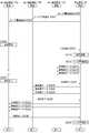
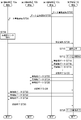
- FIG. 8 is a sequence diagram showing a data rewriting procedure by the communication system 100.
- the management device 16 transmits a data rewrite notification to the third wireless device 10c (S10), transmits a data rewrite notification to the second wireless device 10b (S12), and transmits a data rewrite notification to the first wireless device 10a ( S14). Note that the data rewrite notification to these may be notified.
- the first wireless device 10a to the third wireless device 10c transition to a data standby state.
- the second radio apparatus 10b is turned off (S16) and transmits a status notification to the management apparatus 16 (S18).
- the management device 16 changes the order based on the status notification (S20).
- FIG. 9A and 9B show the data structure of the table stored in the storage unit 58.
- FIG. FIG. 9A shows the changed data rewrite order.
- the priority weight value of the second radio apparatus 10b is set to “105”, and the data rewrite order is set to “1”.
- FIG. 9B will be described later, and the processing returns to FIG.
- the third wireless device 10c starts charging (S22) and transmits a status notification to the management device 16 (S24).
- the management device 16 changes the order based on the status notification (S26).
- FIG. 9B shows the changed data rewrite order. As illustrated, the priority weight value of the third radio apparatus 10c is set to “110”, and the data rewrite order is set to “1”.
- the management device 16 starts data rewriting, that is, updating (S28).
- the management device 16 transmits the wireless device data as update data to the third wireless device 10c (S30, S32, S34).
- the third radio apparatus 10c notifies the management apparatus 16 of the end of reception (S36) and cancels the data waiting state.
- the management device 16 transmits the wireless device data that is update data to the second wireless device 10b (S38, S40, S42).
- the second radio apparatus 10b notifies the management apparatus 16 of the end of reception (S44) and cancels the data waiting state.
- the management device 16 transmits the wireless device data that is update data to the first wireless device 10a (S46, S48, S50).
- the first radio apparatus 10a notifies the management apparatus 16 of the end of reception (S52) and cancels the data waiting state.
- the management device 16 ends the data rewriting (S54).
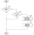
- FIG. 10 is a flowchart showing an update procedure by the management device 16.
- the adjustment unit 56 assigns priority weights corresponding to the “state identification No.”. The value is added to or subtracted from the priority weight value (S74). The adjustment unit 56 changes the data rewriting order in the order of priority weight values (S76).
- the status notification receiving unit 54 does not receive the status notification (N in S70), or when the “Unit ID” does not exist in the table (N in S72), the process is terminated.
- data rewriting is executed preferentially from a wireless device that is highly likely to receive update data, so that data rewriting failures can be suppressed.
- the management device since the management device is notified of a state in which the wireless device is no longer used, such as powering off the wireless device and starting charging, the management device can recognize the state in which the wireless device will not be used. Further, since power off is a sleep state and a state in which the display is turned off and awaits, it is possible to notify a situation that can be unused for a while thereafter. Further, the state of charge can inform the situation that the power source is sufficient and is not used until the charging is completed.
- a wireless device that has not been used has a high possibility of being able to reliably receive data, and can preferentially update data.
- the update process for the wireless device can be efficiently executed according to the state of the wireless device.
- it is notified in advance that data rewriting will be performed soon it is possible to prevent the wireless device from always sending a status notification.
- the second embodiment of the present invention also relates to a communication system that updates a program, data, and the like stored in a wireless device via a wireless line. Also in the second embodiment, in order to efficiently execute the update process for the wireless device according to the state of the wireless device, the management device adjusts the priority order when receiving the status notification from the wireless device, and performs the update process. Execute. In the first embodiment, when the power is turned off or charging is started, the wireless device notifies the fact that there is a high possibility that update data can be received because communication is not performed.
- the wireless device when the wireless device is not used for a certain period of time, the wireless device notifies the fact that there is a high possibility that update data can be received because communication will not be performed.
- the communication system, the wireless device, and the management device according to the second embodiment are the same type as those shown in FIGS. Here, it demonstrates centering on the difference from before.
- the state management unit 24 determines that the wireless device 10 is not in use when the wireless device 10 does not perform any operation after the timer is started until the timer expires. This corresponds to measuring a period during which communication processing is not executed, and the state management unit 24 can also be said to be a measurement unit. Note that the state management unit 24 resets and restarts the timer when the wireless device 10 operates from when the timer starts to when the timer expires.
- the state management unit 24 refers to the storage unit 26 to identify the “state identification number” corresponding to the acquired state. Here, for example, “state identification No.” corresponding to the state “expiration of operation monitoring timer” is specified.
- the status transmission unit 28 inputs “status identification No.” indicating the status of the wireless device 10 from the status management unit 24.
- the status transmission unit 28 generates a status notification based on the “status identification No.” and transmits the status notification to the management device 16. This corresponds to the state transmission unit 28 transmitting to the management device 16 a state notification indicating that the period measured by the state management unit 24 has reached a certain period.
- FIG. 11 is a sequence diagram showing a data rewriting procedure by the communication system 100 according to the second embodiment of the present invention.
- the management device 16 transmits a data rewrite notification to the third wireless device 10c (S100), transmits a data rewrite notification to the second wireless device 10b (S102), and transmits a data rewrite notification to the first wireless device 10a ( S104).
- the first wireless device 10a to the third wireless device 10c transition to a data standby state.
- the first wireless device 10a, the second wireless device 10b, and the third wireless device 10c start timers (S106, S108, S110).
- a call is started between the first radio apparatus 10a and the second radio apparatus 10b (S112).
- the third radio apparatus 10c expires the timer (S114).
- the call is terminated between the first wireless device 10a and the second wireless device 10b (S116).
- the first radio apparatus 10a and the second radio apparatus 10b restart the timer (S118, S120).
- the third wireless device 10c transmits a status notification to the management device 16 (S122).
- the management device 16 changes the order based on the status notification (S124).
- FIG. 12 shows the data structure of the table stored in the storage unit 58 according to the second embodiment of the present invention. As illustrated, the priority weight value of the third radio apparatus 10c is set to “103”, and the data rewrite order is set to “1”. Returning to FIG.
- the management device 16 starts data rewriting, that is, updating (S126).
- the management device 16 transmits the wireless device data as update data to the third wireless device 10c (S128, S130, S132).
- the third wireless device 10c notifies the management device 16 of the end of reception (S134) and cancels the data waiting state.
- the management device 16 transmits wireless data that is update data to the first wireless device 10a (S136, S138, S140).
- the first radio apparatus 10a notifies the management apparatus 16 of the end of reception (S142) and cancels the data waiting state.
- the management device 16 transmits wireless data that is update data to the second wireless device 10b (S144, S146, S148).
- the second radio apparatus 10b notifies the management apparatus 16 of the end of reception (S150) and cancels the data standby state.
- the management device 16 ends the data rewriting (S152).
- the system since the system is notified that the wireless device has not been operated for a certain period of time, it is relatively highly likely that the wireless device will remain unused and receive data for a while. Data can be preferentially updated from the device.
- the user of the wireless device since the user of the wireless device does not need a special operation and automatically notifies the management device if there is no operation of the wireless device, the convenience of the user can be improved.
- the state of the wireless device can be notified even when used for a long time (operation without powering off or charging).
- the third embodiment of the present invention also relates to a communication system that updates a program, data, and the like stored in a wireless device via a wireless line, as before.
- the management device adjusts the priority order when receiving the status notification from the wireless device, and performs the update process. Execute.
- the wireless device when the power is turned off or charging is started, the wireless device notifies the fact that there is a high possibility that update data can be received because communication is not performed.
- the wireless device notifies that there is a high possibility that the update data cannot be received when the transmission of voice or data is started.
- the communication system, the wireless device, and the management device according to the third embodiment are the same types as those in FIGS. Here, it demonstrates centering on the difference from before.
- the state management unit 24 acquires a state in which the wireless device 10 is used.
- the state management unit 24 refers to the storage unit 26 to identify the “state identification number” corresponding to the acquired state.
- “state identification No.” corresponding to the state “transmission start” is specified.
- the state transmission unit 28 inputs “state identification No.” indicating the state of the wireless device 10 from the state management unit 24.
- the status transmission unit 28 generates a status notification based on the “status identification No.” and transmits the status notification to the management device 16. After the status transmission unit 28 transmits the status notification, the communication unit 20 performs transmission such as voice transmission and data transmission.
- FIG. 13 is a sequence diagram showing a data rewriting procedure by the communication system 100 according to the third embodiment of the present invention.
- the management device 16 transmits a data rewrite notification to the third wireless device 10c (S200), transmits a data rewrite notification to the second wireless device 10b (S202), and transmits a data rewrite notification to the first wireless device 10a ( S204).
- the first wireless device 10a to the third wireless device 10c transition to a data standby state.
- the first radio apparatus 10a starts transmission (S206) and transmits a status notification to the management apparatus 16 (S208).
- the management device 16 changes the order based on the status notification (S210).
- FIG. 1 is a sequence diagram showing a data rewriting procedure by the communication system 100 according to the third embodiment of the present invention.
- the management device 16 transmits a data rewrite notification to the third wireless device 10c (S200), transmits a data rewrite notification to the second wireless device 10b (S202), and transmits
- the management device 16 starts data rewriting, that is, updating (S212).
- the management device 16 transmits the wireless device data that is update data to the third wireless device 10c (S214, S216, S218).
- the third wireless device 10c notifies the management device 16 of the end of reception (S220) and cancels the data standby state.
- the management device 16 transmits wireless data that is update data to the second wireless device 10b (S222, S224, S226).
- the second radio apparatus 10b notifies the management apparatus 16 of the end of reception (S228) and cancels the data waiting state.
- the management device 16 transmits wireless data that is update data to the first wireless device 10a (S230, S232, S234).
- the first radio apparatus 10a notifies the management apparatus 16 of the end of reception (S236) and cancels the data waiting state.
- the management device 16 ends the data rewriting (S238).
- the management device 16 When the first wireless device 10a is continuing transmission, the wireless device data (S230, S232, S234) cannot be received, so the management device 16 does not transmit the wireless device data (S230, S232, S234). May be.
- S208 is the status notification, the fact that it is in the transmission state itself may be the status notification.
- the management device 16 may transmit the wireless device data (S230, S232, S234) after it is confirmed that the first wireless device 10a has ended transmission (S207) and is in a transmission state. .
- the wireless device by notifying the system that voice or data is being transmitted, the wireless device is used for a while, so that the state where data cannot be rewritten continues. It is possible to inform that the possibility is relatively high. Further, since the data rewriting order of the wireless device is lowered and the data is updated, data rewriting can be started from another wireless device that is not currently used. Further, the higher the frequency of calls, the higher the frequency of updating the data rewriting order and the lower the priority of data rewriting. Therefore, it is possible to obtain an efficient data rewriting order that more closely matches the actual usage situation.
- the fourth embodiment of the present invention also relates to a communication system that updates a program, data, and the like stored in a wireless device via a wireless line, as before.
- the management device receives the status notification from the wireless device and adjusts the priority order to perform the update process. Execute.
- the wireless device when the power is turned off or charging is started, the wireless device notifies the fact that there is a high possibility that update data can be received because communication is not performed.
- the wireless device when the wireless device enters the Scan mode, the wireless device waits for reception from now on, so that it is highly likely that update data can be received.
- the communication system, the wireless device, and the management device according to the fourth embodiment are the same types as those in FIGS. Here, it demonstrates centering on the difference from before.
- the state management unit 24 acquires the state of the wireless device 10.
- the state of notification is different when the scan target includes a channel capable of receiving update data and when the scan target does not include a channel capable of receiving update data.
- the state management unit 24 refers to the storage unit 26 to identify the “state identification number” corresponding to the acquired state.
- “state identification No.” corresponding to the state “Scan start (Data reception is possible)” is specified.
- “state identification No.” corresponding to the state “Scan start (data not received)” is specified.
- the state transmission unit 28 inputs “state identification No.” indicating the state of the wireless device 10 from the state management unit 24.
- the status transmission unit 28 generates a status notification based on the “status identification No.” and transmits the status notification to the management device 16.
- the adjustment unit 56 in FIG. 5 refers to another table stored in the storage unit 58 based on the acquired “state identification No.” and refers to another table illustrated in FIG. A priority weighting value corresponding to the state is derived.
- the priority weight value “+3” is derived
- the priority weight value “ ⁇ 3” is derived. 10 "is derived.
- the adjustment unit 56 updates the priority weight value of “Unit_ID” in the table stored in the storage unit 58 and in the table shown in FIG. 6 according to the derived priority weight value. Therefore, the data rewrite order increases when the scan target includes a channel capable of receiving update data, and the data rewrite order decreases when the scan target does not include a channel capable of receiving update data.
- FIG. 15 is a sequence diagram illustrating a data rewriting procedure by the communication system 100 according to the fourth embodiment of the present invention.
- the management device 16 transmits a data rewrite notification to the third wireless device 10c (S300), transmits a data rewrite notification to the second wireless device 10b (S302), and transmits a data rewrite notification to the first wireless device 10a (S302). S304).
- the first wireless device 10a to the third wireless device 10c transition to a data standby state.
- the third radio apparatus 10c starts Scan Mode with the data rewrite CH as a scan target (S306) and transmits a status notification to the management apparatus 16 (S308).
- the management device 16 changes the order based on the status notification (S310).
- FIGS. 16A and 16B show the data structure of the table stored in the storage unit 58 according to the fourth embodiment of the present invention.
- FIG. 16A shows the changed data rewrite order. As illustrated, the priority weight value of the third radio apparatus 10c is set to “103”, and the data rewrite order is set to “1”.
- FIG. 16B will be described later, and the processing returns to FIG.
- the first radio apparatus 10a performs an operation for starting Scan Mode that does not target the data rewrite CH as a scan target (S312), and transmits a status notification to the management apparatus 16 (S314).
- the first radio apparatus 10a starts an operation of Scan Mode that does not target the data rewriting CH as a Scan target (S315).
- the management device 16 changes the order based on the status notification (S316).
- FIG. 16B shows the changed data rewrite order. As illustrated, the priority weight value of the first radio apparatus 10a is set to “90”, and the data rewrite order is set to “3”.
- the management device 16 starts data rewriting, that is, updating (S318).
- the management device 16 transmits the wireless device data that is update data to the third wireless device 10c (S320, S322, S324).
- the third wireless device 10c notifies the management device 16 of the end of reception (S326) and cancels the data standby state.
- the management device 16 transmits the wireless device data that is the update data to the second wireless device 10b (S328, S330, S332).
- the second radio apparatus 10b notifies the management apparatus 16 of the end of reception (S334) and cancels the data waiting state.
- the management device 16 transmits the wireless device data that is the update data to the first wireless device 10a (S336, S338, S340).
- the first radio apparatus 10a notifies the management apparatus 16 of the end of reception (S342) and cancels the data waiting state.
- the management device 16 ends the data rewriting (S344).
- the management apparatus since the management apparatus is notified that Scan has been started, it can be predicted that the reception will be waited for a while. Further, if the channel for data rewriting is a Scan target, it can be notified that the possibility that data rewriting can be received is relatively high.
- the Scan target is not necessarily a channel that can be notified of the status, so by sending a status notification before starting Scan after the operation, It is possible to inform that data rewrite cannot be received.
- it is possible to update the data rewriting order in consideration of the case where the wireless device is waiting for reception more cases can be dealt with.
- the fifth embodiment of the present invention also relates to a communication system that updates a program, data, and the like stored in a wireless device via a wireless line, as before. Also in the fifth embodiment, in order to efficiently execute the update process for the wireless device according to the state of the wireless device, the management device adjusts the priority order when receiving the status notification from the wireless device, and performs the update process. Execute. In the first embodiment, when the power is turned off or charging is started, the wireless device notifies the fact that there is a high possibility that update data can be received because communication is not performed.
- the wireless device when the wireless device changes to a channel that cannot receive update data, the wireless device notifies that the update data cannot be received from now on.
- the communication system, the wireless device, and the management device according to the fifth embodiment are the same type as those shown in FIGS. Here, it demonstrates centering on the difference from before.
- the state management unit 24 acquires the state of the wireless device 10. More specifically, when the wireless device 10 in the data standby state changes the channel, the state management unit 24 acquires the state of the wireless device 10. Here, a status notification is transmitted to the system. However, the state of notification differs depending on whether or not the channel setting can receive update data.
- the state management unit 24 refers to the storage unit 26 to identify the “state identification number” corresponding to the acquired state.
- the “state identification No.” corresponding to the state “CH change (Data reception is possible)” is specified.
- the “state identification No.” corresponding to the state “CH change (data reception not possible)” is specified.
- the state transmission unit 28 inputs “state identification No.” indicating the state of the wireless device 10 from the state management unit 24.
- the status transmission unit 28 generates a status notification based on the “status identification No.” and transmits the status notification to the management device 16. Note that status notifications are not sent during Scan Mode.
- the adjustment unit 56 in FIG. 5 refers to another table stored in the storage unit 58 based on the acquired “state identification No.” and refers to another table illustrated in FIG. A priority weighting value corresponding to the state is derived.
- the priority weight value is returned to the initial value
- the adjustment unit 56 updates the priority weight value of “Unit_ID” in the table stored in the storage unit 58 and in the table shown in FIG. 6 according to the derived priority weight value. Therefore, when the update data is changed to a receivable channel, the data rewrite order returns to the initial value, and when the update data is changed to a non-receivable channel, the data rewrite order is lowered.
- FIG. 17 is a sequence diagram showing a data rewrite procedure by the communication system 100 according to the fifth embodiment of the present invention.
- the management device 16 transmits a data rewrite notification to the third wireless device 10c (S400), transmits a data rewrite notification to the second wireless device 10b (S402), and transmits a data rewrite notification to the first wireless device 10a ( S404).
- the first wireless device 10a to the third wireless device 10c transition to a data standby state.
- a channel change operation is performed to other than the Data reception CH (S405), and a status notification is transmitted to the management apparatus 16 (S406).
- the first radio apparatus 10a changes the CH to other than the Data reception CH (S408).
- the management device 16 changes the order based on the status notification (S410).
- 18A and 18B show the data structure of the table stored in the storage unit 58 according to the fifth embodiment of the present invention.
- FIG. 18A shows the changed data rewrite order. As illustrated, the priority weight value of the first radio apparatus 10a is set to “90”, and the data rewrite order is set to “3”.
- FIG. 18B will be described later, and the processing returns to FIG.
- the first radio apparatus 10a changes the CH to the Data reception CH (S412), and transmits a status notification to the management apparatus 16 (S414).
- the management device 16 changes the order based on the status notification (S416).
- FIG. 18B shows the changed data rewrite order. As illustrated, the priority weight value of the first radio apparatus 10a is returned to “100”. Returning to FIG.
- the management device 16 starts data rewriting, that is, updating (S418).
- the management device 16 transmits the wireless device data that is update data to the third wireless device 10c (S420, S422, S424).
- the third wireless device 10c notifies the management device 16 of the end of reception (S426) and cancels the data standby state.
- the management device 16 transmits the wireless device data that is update data to the second wireless device 10b (S428, S430, S432).
- the second radio apparatus 10b notifies the management apparatus 16 of the end of reception (S434) and cancels the data waiting state.
- the management device 16 transmits wireless data that is update data to the first wireless device 10a (S436, S438, S440).
- the first wireless device 10a notifies the management device 16 of the end of reception (S442) and cancels the data standby state.
- the management device 16 ends the data rewriting (S444).
- the management apparatus since the management apparatus is notified that the channel has been changed or is being changed, it can be determined whether or not the wireless apparatus can receive the update data. Further, when the channel is changed to a channel that cannot receive update data, it can be notified that the update data cannot be received until the channel is changed to a channel that can receive update data.
- the status notification is not always possible for channels other than the channel that receives the update data. Therefore, the update data cannot be received after the operation is changed to a channel that cannot receive the update data. Notify status before changes are made to the channel.
- the data rewriting efficiency can be further improved by lowering the data rewriting order more than when the wireless device is used.
- the sixth embodiment of the present invention also relates to a communication system that updates a program, data, and the like stored in a wireless device via a wireless line, as before. Also in the sixth embodiment, in order to efficiently execute the update process for the wireless device according to the state of the wireless device, the management device adjusts the priority order when receiving the status notification from the wireless device, and performs the update process. Execute. In the first embodiment, when the power is turned off or charging is started, the wireless device notifies the fact that there is a high possibility that update data can be received because communication is not performed.
- the user of the wireless device does not use the wireless device by his / her own operation, and thus there is a high possibility that the update data can be received, or the update data cannot be received because the wireless device is used. Notify that the condition is high.
- the communication system, the wireless device, and the management device according to the sixth embodiment are the same types as those in FIGS. 1, 2, and 5. Here, it demonstrates centering on the difference from before.
- the state management unit 24 acquires the state of the wireless device 10. Specifically, in the wireless device 10 in a data standby state, when an update data request is input according to an instruction from a user, the state management unit 24 acquires a state in which the wireless device 10 is not used.
- the state management unit 24 refers to the storage unit 26 to identify the “state identification number” corresponding to the acquired state. Here, for example, “state identification No.” corresponding to the state “data rewrite request” is specified.
- the state transmission unit 28 inputs “state identification No.” indicating the state of the wireless device 10 from the state management unit 24.
- the status transmission unit 28 generates a status notification based on the “status identification No.” and transmits the status notification to the management device 16.
- FIG. 19 is a sequence diagram showing a data rewriting procedure by the communication system 100 according to the sixth embodiment of the present invention.
- the management device 16 transmits a data rewrite notification to the third wireless device 10c (S500), transmits a data rewrite notification to the second wireless device 10b (S502), and transmits a data rewrite notification to the first wireless device 10a ( S504).
- the first wireless device 10a to the third wireless device 10c transition to a data standby state.
- the third wireless device 10c receives a data rewrite request (S506) and transmits a status notification to the management device 16 (S508).
- the management device 16 changes the order based on the status notification (S510).
- the management device 16 starts data rewriting, that is, update (S512).
- the management device 16 transmits the wireless device data as update data to the third wireless device 10c (S514, S516, S518).
- the third wireless device 10c notifies the management device 16 of the end of reception (S520) and cancels the data standby state.
- the management device 16 transmits wireless data that is update data to the second wireless device 10b (S522, S524, S526).
- the second radio apparatus 10b notifies the management apparatus 16 of the end of reception (S528) and cancels the data waiting state.
- the management device 16 transmits the wireless device data that is the update data to the first wireless device 10a (S530, S532, S534).
- the first radio apparatus 10a notifies the management apparatus 16 of the end of reception (S536) and cancels the data waiting state.
- the management device 16 ends the data rewriting (S538).
- the data rewriting order can be improved.
- the user actively notifies the management device that the data can be rewritten without using the wireless device from now on it is possible to improve the accuracy of changing the data rewriting order.
- Example 7 also relates to a communication system that updates a program, data, and the like stored in a wireless device via a wireless line, as before. Also in the seventh embodiment, in order to efficiently execute the update process for the wireless device according to the state of the wireless device, the management device adjusts the priority order when receiving the status notification from the wireless device, and performs the update process. Execute. In the first embodiment, when the power is turned off or charging is started, the wireless device notifies the fact that there is a high possibility that update data can be received because communication is not performed.
- the seventh embodiment when the reception radio wave environment in the wireless device is bad, it is notified that there is a high possibility that update data cannot be received due to a low electric field.
- the communication system, the wireless device, and the management device according to the seventh embodiment are the same types as those in FIGS. Here, it demonstrates centering on the difference from before.
- the state management unit 24 acquires the state. More specifically, when the electric field strength with respect to the signal received by the communication unit 20 is low, for example, when the RSSI value is ⁇ 110 dBm or less, the state management unit 24 acquires the state.
- the state management unit 24 refers to the storage unit 26 to identify the “state identification number” corresponding to the acquired state. Here, for example, “state identification No.” corresponding to the state “electric field strength reduction” is specified.
- the state transmission unit 28 inputs “state identification No.” indicating the state of the wireless device 10 from the state management unit 24.
- the status transmission unit 28 generates a status notification based on the “status identification No.” and transmits the status notification to the management device 16.
- FIG. 21 is a sequence diagram showing a data rewrite procedure by the communication system 100 according to the seventh embodiment of the present invention.
- the management device 16 transmits a data rewrite notification to the third wireless device 10c (S600), transmits a data rewrite notification to the second wireless device 10b (S602), and transmits a data rewrite notification to the first wireless device 10a (S602). S604).
- the first wireless device 10a to the third wireless device 10c transition to a data standby state.
- the first radio apparatus 10a detects that the electric field strength is low (S606), and transmits a status notification to the management apparatus 16 (S608).
- the management device 16 changes the order based on the status notification (S610).
- FIG. 22 shows a data structure of a table stored in the storage unit 58 according to the seventh embodiment of the present invention. As illustrated, the priority weight value of the first radio apparatus 10a is set to “97”, and the data rewrite order is set to “3”. Returning to FIG. The management device 16 starts data rewriting, that is, updating (S612).
- the management device 16 transmits the wireless device data as update data to the third wireless device 10c (S614, S616, S618).
- the third wireless device 10c notifies the management device 16 of the end of reception (S620) and cancels the data standby state.
- the management device 16 transmits wireless data that is update data to the second wireless device 10b (S622, S624, S626).
- the second radio apparatus 10b notifies the management apparatus 16 of the end of reception (S628) and cancels the data waiting state.
- the management device 16 transmits wireless data that is update data to the first wireless device 10a (S630, S632, S634).
- the first radio apparatus 10a notifies the management apparatus 16 of the end of reception (S636) and cancels the data waiting state.
- the management device 16 ends the data rewriting (S638).
- the reception device since the reception radio wave environment is bad, the reception device itself is notified to the management device, so the data for the radio device that is likely to be unable to receive after that because the reception radio wave environment is bad.
- the rewrite order can be lowered.
- rewriting to a wireless device having a poor reception radio wave environment often involves a retry operation, and may occupy the rewriting frequency for a long time, and can be suppressed.
- Example 8 Next, Example 8 will be described.
- the eighth embodiment of the present invention also relates to a communication system that updates a program, data, and the like stored in a wireless device via a wireless line, as before.
- the management device adjusts the priority order when receiving the status notification from the wireless device, and performs the update process. Execute.
- the wireless device when the power is turned off or charging is started, the wireless device notifies the fact that there is a high possibility that update data can be received because communication is not performed.
- Example 8 when it is confirmed that the mobile device is moving based on the input from the acceleration sensor provided in the wireless device, there is a high possibility that update data cannot be received because the wireless device 10 will be used from now on. Notify that it is in a state.
- the communication system, the wireless device, and the management device according to the eighth embodiment are the same type as those shown in FIGS. Here, it demonstrates centering on the difference from before.
- the state management unit 24 acquires the state of the wireless device 10. Specifically, when the detection result by the acceleration sensor provided in the wireless device 10 indicates movement, for example, when the detected acceleration is larger than the threshold value, the state management unit 24 displays the movement state. get.
- the state management unit 24 refers to the storage unit 26 to identify the “state identification number” corresponding to the acquired state. Here, for example, “state identification No.” corresponding to the state “acceleration sensor detection” is specified.
- the state transmission unit 28 inputs “state identification No.” indicating the state of the wireless device 10 from the state management unit 24.
- the status transmission unit 28 generates a status notification based on the “status identification No.” and transmits the status notification to the management device 16.
- FIG. 23 is a sequence diagram showing a data rewriting procedure by the communication system 100 according to the eighth embodiment of the present invention.
- the management device 16 transmits a data rewrite notification to the third wireless device 10c (S700), transmits a data rewrite notification to the second wireless device 10b (S702), and transmits a data rewrite notification to the first wireless device 10a ( S704).
- the first wireless device 10a to the third wireless device 10c transition to a data standby state.
- the first wireless device 10a acquires acceleration sensor detection (S706) and transmits a status notification to the management device 16 (S708).
- the management device 16 changes the order based on the status notification (S710).
- FIG. 24 shows a data structure of a table stored in the storage unit 58 according to the eighth embodiment of the present invention. As illustrated, the priority weight value of the first radio apparatus 10a is set to “95”, and the data rewrite order is set to “3”. Returning to FIG. The management device 16 starts data rewriting, that is, updating (S712).
- the management device 16 transmits the wireless device data as update data to the third wireless device 10c (S714, S716, S718).
- the third wireless device 10c notifies the management device 16 of the end of reception (S720) and cancels the data waiting state.
- the management device 16 transmits wireless data that is update data to the second wireless device 10b (S722, S724, S726).
- the second radio apparatus 10b notifies the management apparatus 16 of the end of reception (S728) and cancels the data waiting state.
- the management device 16 transmits wireless data that is update data to the first wireless device 10a (S730, S732, S734).
- the first radio apparatus 10a notifies the management apparatus 16 of the end of reception (S736) and cancels the data waiting state.
- the management device 16 ends the data rewriting (S738).
- the data rewriting order can be lowered for a moving wireless device. Since the wireless device is likely to be in use during movement, the data rewriting order of the wireless device in use can be lowered and the data rewriting order of the unused wireless device can be raised in actual operation. In addition, since the data rewriting order of the unused wireless device is increased, data rewriting can be executed from the unused wireless device.
- the ninth embodiment of the present invention also relates to a communication system that updates programs, data, and the like stored in a wireless device via a wireless line, as before. Also in the ninth embodiment, in order to efficiently execute the update process for the wireless device according to the state of the wireless device, when the management device receives the state notification of the wireless device, the management device adjusts the priority order and performs the update process. Execute.
- the management device is connected to the trunking device, and the wireless device performs communication via the trunking device.
- the trunking device executes control in the trunking system.
- a trunking system is a system that automatically allocates a free call channel in communication via a relay device.
- the communication partner When communication is started, the communication partner is called on the control channel to the relay device, and this communication is transferred to a call channel in which the trunking system is free.
- the trunking device since communication is always performed via a relay device, the trunking device can grasp the state of each wireless device. Therefore, the management device receives the status of each wireless device from the trunking device as a status notification. The management device executes the same processing as before based on the status notification.
- the management apparatus according to the ninth embodiment is the same type as that shown in FIG. Here, it demonstrates centering on the difference from before.
- FIG. 25 shows a configuration of a communication system 100 according to the ninth embodiment of the present invention.
- the communication system 100 includes a first wireless device 10 a, a second wireless device 10 b, a third wireless device 10 c, a trunking device 18, a network 14, and a management device 16 that are collectively referred to as the wireless device 10.
- the management device 16 manages update data for updating each of the plurality of wireless devices 10.
- the management device 16 transmits the same data rewrite notification as before to the wireless device 10 via the trunking device 18.
- the trunking device 18 controls the communication state of each of the plurality of wireless devices 10.
- the wireless device 10 that has received the data rewrite notification transitions to a data standby state.
- the wireless device 10 in a data standby state performs “Voice Call” and “Emergency Call” via the trunking device 18. In this way, the call and authentication operations in the wireless device 10 are notified to the trunking device 18 every time.
- the trunking device 18 transmits Log information of such an operation as a status notification.
- FIG. 26 shows the data structure of a table stored in the storage unit 58 according to the ninth embodiment of the present invention. This is shown in the same manner as the table shown in FIG. Returning to FIG. The management device 16 adjusts the priority order for each of the plurality of wireless devices 10 based on the acquired state.
- FIG. 27 shows the data structure of another table stored in the storage unit 58 according to the ninth embodiment of the present invention. This is shown in the same manner as in FIG. 7, but here, a state different from that in FIG. 7 will be described.
- “Returning the priority weight value to the initial value” is set for the state “Registration”.
- the priority weighting value “ ⁇ 3” is set for the state “Group Call”. This is the case when a group call is being executed.
- the priority weighting value “ ⁇ 5” is set against that set for the state “Individual Call”. This is an individual call, and the call time of the individual call tends to be longer than the call time of the group call, so the priority weighting value is lower than the priority weighting value of the group call.
- the priority weighting value “ ⁇ 10” is set for the state “Emergency Call”. This is an emergency call. “Remove from data update target”, that is, “Remove from data rewrite target” is set for the state “Registration Clear”. This is to start roaming to another system and is not subject to data update.
- the management device 16 calculates the priority weight value as before, and adjusts the data rewrite order based on the priority weight value.
- the management device 16 transmits the update data to each of the plurality of wireless devices 10 via the trunking device 18 in the order according to the priority order that is the data rewriting order.
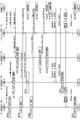
- FIG. 28 is a sequence diagram illustrating a data rewriting procedure performed by the communication system 100.
- the management device 16 transmits a data rewrite notification to the trunking device 18 (S800), and the trunking device 18 transmits a data rewrite notification to the first wireless device 10a (S802).
- the first radio apparatus 10a transitions to a data standby state (S804).
- the management device 16 transmits a data rewrite notification to the trunking device 18 (S806), and the trunking device 18 transmits a data rewrite notification to the second wireless device 10b (S808).
- the second radio apparatus 10b transitions to a data standby state (S810).
- the management device 16 transmits a data rewrite notification to the trunking device 18 (S812), and the trunking device 18 transmits a data rewrite notification to the third wireless device 10c (S814).
- the third radio apparatus 10c transitions to a data standby state (S816).
- the first radio apparatus 10a starts “Voice Call” (S818).
- the first radio apparatus 10a transmits “Voice Call (Individual Call)” to the trunking apparatus 18 (S820), and the trunking apparatus 18 transmits “Communication Log information” to the management apparatus 16 (S822).
- the trunking device 18 transmits “Voice Call (Individual Call)” to the second wireless device 10b (S824).
- the second radio apparatus 10b receives (S826).
- the management device 16 changes the order based on the status notification “Communication Log information” (S828).
- FIGS. 29A to 29C show the data structure of the table stored in the storage unit 58.
- FIG. FIG. 29A shows the changed data rewrite order.
- the priority weight values of the first radio apparatus 10a and the second radio apparatus 10b are set to “95”, and the data rewrite order thereof is set to “2” and “3”.
- FIGS. 29B to 29C will be described later, and the processing returns to FIG.
- the first radio apparatus 10a starts “Emergency Call” (S830).
- the first radio apparatus 10a transmits “Emergency Call” to the trunking apparatus 18 (S832), and the trunking apparatus 18 transmits “Communication Log information” to the management apparatus 16 (S834).
- the management device 16 changes the order based on the status notification “Communication Log information” (S836).
- FIG. 29B shows the changed data rewrite order. As illustrated, the priority weight value of the first radio apparatus 10a is set to “85”, and the data rewrite order thereof is set to “3”.
- FIG. 29C will be described later, and the processing returns to FIG.
- the third wireless device 10c changes “System (Zone)” to the trunking device 18 (S838).
- the third radio apparatus 10c transmits “Registration Clear” to the trunking apparatus 18 (S840), and the trunking apparatus 18 transmits “Communication Log information” to the management apparatus 16 (S842).
- the third wireless device 10c releases the data standby state (S844).
- the management device 16 changes the order based on the status notification “Communication Log information” (S846).
- FIG. 29C shows the changed data rewrite order. As illustrated, the third wireless device 10c is excluded.
- the management device 16 starts data rewriting, that is, updating (S848).
- the management device 16 transmits the wireless device data as update data to the trunking device 18 (S850), and the trunking device 18 transmits the wireless device data to the second wireless device 10b (S852).
- the management device 16 transmits the wireless device data as update data to the trunking device 18 (S854), and the trunking device 18 transmits the wireless device data to the second wireless device 10b (S856).
- the second wireless device 10b notifies the trunking device 18 of the end of reception (S858), and the trunking device 18 notifies the management device 16 of the end of reception (S860).
- the second radio apparatus 10b releases the data standby state (S862).
- the management device 16 transmits the wireless device data as update data to the trunking device 18 (S864), and the trunking device 18 transmits the wireless device data to the first wireless device 10a (S866).
- the management device 16 transmits the wireless device data as update data to the trunking device 18 (S868), and the trunking device 18 transmits the wireless device data to the first wireless device 10a (S870).
- the first wireless device 10a notifies the trunking device 18 of the end of reception (S872), and the trunking device 18 notifies the management device 16 of the end of reception (S874).
- the first radio apparatus 10a cancels the data standby state (S876).
- the management device 16 ends the data rewriting (S878).
- the status of transmission operation, channel change (zone change), Voice Call, and Registration can be known from the log information.
- the data rewrite order is updated from the log information, it is possible to eliminate the need to send a status notification from the wireless device.
- the Call type such as Individual Call, Group Call, and Emergency Call is determined from the log information, the data rewrite order can be changed depending on the type.
- update data cannot be received when the roaming of another system is started, it is possible to suppress the time required for data rewriting failure and time by excluding it from the target wireless device for data rewriting.
- the communication system 100 uses business radio.
- the present invention is not limited to this.
- a wireless communication system other than commercial radio may be used.
- the degree of freedom of configuration can be improved.
- the data rewrite notification is transmitted from the management device 16 to the wireless device 10.
- the present invention is not limited to this.
- the data rewrite notification may not be transmitted.
- the management device 16 appropriately acquires the status notification.
- the management device can automatically acquire the status notification.
- the update process for the wireless device can be efficiently executed in accordance with the state of the wireless device.
Landscapes
- Engineering & Computer Science (AREA)
- Computer Networks & Wireless Communication (AREA)
- Signal Processing (AREA)
- Theoretical Computer Science (AREA)
- Databases & Information Systems (AREA)
- Physics & Mathematics (AREA)
- General Engineering & Computer Science (AREA)
- General Physics & Mathematics (AREA)
- Mobile Radio Communication Systems (AREA)
- Information Transfer Between Computers (AREA)
Abstract
状態通知受信部54は、複数の無線装置のそれぞれから、当該無線装置の状態に関する状態通知を受信する。調節部56は、状態通知受信部54において受信した状態通知をもとに、複数の無線装置のそれぞれに対する優先順位を調節する。更新データ送信部60は、調節部56において調節した優先順位に応じた順番によって、複数の無線装置のそれぞれに対して、当該無線装置を更新させるための更新データを送信する。
Description
本発明は、通信技術に関し、特に更新データを伝送する管理装置、無線装置、通信システム、管理方法に関する。
電子機器に記憶されたプログラムやデータをアップデートすべき場合が生じる。このようなアップデートは、例えば、無線回線を介してなされる。その際、基地局装置は、アップデートの対象となる電子機器に対してリクエストを送信する。さらに、基地局装置は、リクエストを送信した後、スリープ状態から復帰した電子機器に対して、アップデート内容を送信する(例えば、特許文献1)。
無線回線を介してアップデート内容を送信する場合、電子機器である無線装置がアップデート可能な状態であることが必要とされる。アップデート可能な状態とは、アップデート内容を受信可能であるとともに、受信したアップデート内容を反映させる処理を実行可能な状態である。その一例は、スリープ状態からの復帰であるが、それ以外にもさまざまな状態が含まれる。そのため、無線装置のさまざまな状態に応じて、アップデートのような更新処理を効率的に実行することが望まれる。
本発明はこうした状況に鑑みてなされたものであり、その目的は、無線装置の状態に応じて無線装置に対する更新処理を効率的に実行する技術を提供することである。
上記課題を解決するために、本発明のある態様の管理装置は、複数の無線装置のそれぞれから、当該無線装置の状態に関する状態通知を受信する受信部と、受信部において受信した状態通知をもとに、複数の無線装置のそれぞれに対する優先順位を調節する調節部と、調節部において調節した優先順位に応じた順番によって、複数の無線装置のそれぞれに対して、当該無線装置を更新させるための更新データを送信する送信部と、を備える。
本発明の別の態様は、無線装置である。この装置は、無線装置の状態を取得する状態管理部と、状態管理部が取得した状態の取得されうる複数の状態と、各状態を識別するための状態識別番号を対応づけて記憶した記憶部と、無線装置の更新データまたは更新データの書換通知を受信する通信部と、通信部が更新データの書換通知を受信した際に、状態管理部が無線装置の状態を取得し、更新データの更新開始の優先順位を変更させるため、取得した情報の状態識別番号を送信する状態通知を行う状態送信部を備える。
本発明のさらに別の態様は、通信システムである。この通信システムは、複数の無線装置と、複数の無線装置のそれぞれを更新させるための更新データを管理する管理装置とを備える。管理装置は、複数の無線装置のそれぞれから、当該無線装置の状態に関する状態通知を受信すると、状態通知をもとに複数の無線装置のそれぞれに対する優先順位を調節し、優先順位に応じた順番によって複数の無線装置のそれぞれに更新データを送信する。
本発明のさらに別の態様もまた、通信システムである。この通信システムは、複数の無線装置と、複数の無線装置のそれぞれの通信状態を制御するトランキング装置と、複数の無線装置のそれぞれを更新させるための更新データを管理する管理装置とを備える。管理装置は、トランキング装置から、複数の無線装置のそれぞれの状態に関する状態通知を受信すると、状態通知をもとに複数の無線装置のそれぞれに対する優先順位を調節し、優先順位に応じた順番によって複数の無線装置のそれぞれに更新データをトランキング装置経由で送信する。
本発明のさらに別の態様は、管理方法である。この方法は、複数の無線装置のそれぞれから、当該無線装置の状態に関する状態通知を受信するステップと、受信した状態通知をもとに、複数の無線装置のそれぞれに対する優先順位を調節するステップと、調節した優先順位に応じた順番によって、複数の無線装置のそれぞれに対して、当該無線装置を更新させるための更新データを送信するステップと、を備える。
なお、以上の構成要素の任意の組合せ、本発明の表現を方法、装置、システム、記録媒体、コンピュータプログラムなどの間で変換したものもまた、本発明の態様として有効である。
本発明によれば、無線装置の状態に応じて無線装置に対する更新処理を効率的に実行できる。
(実施例1)
本発明を具体的に説明する前に、まず概要を述べる。本発明の実施例1は、無線装置に記憶されたプログラム、データ等を無線回線経由で更新する通信システムに関する。無線回線として、例えば、業務用無線が使用される。業務用無線は、予め定められた無線CHにおいて音声通信を実行する。音声通信の一例がPTT(Push to Talk)である。PTTでは、ユーザが、会話中にボタンを押し、会話終了時にボタンを解放する。また、業務用無線では、複数の無線装置によってグループを形成することも可能である。業務用無線の基地局装置は、グループに対して、上りチャネルと下りチャネルを割り当てる。このような状況下において、グループ中の1つの無線装置が、上りチャネルにて信号を送信し、グループ中の他の無線装置が、下りチャネルにて信号を受信する。
本発明を具体的に説明する前に、まず概要を述べる。本発明の実施例1は、無線装置に記憶されたプログラム、データ等を無線回線経由で更新する通信システムに関する。無線回線として、例えば、業務用無線が使用される。業務用無線は、予め定められた無線CHにおいて音声通信を実行する。音声通信の一例がPTT(Push to Talk)である。PTTでは、ユーザが、会話中にボタンを押し、会話終了時にボタンを解放する。また、業務用無線では、複数の無線装置によってグループを形成することも可能である。業務用無線の基地局装置は、グループに対して、上りチャネルと下りチャネルを割り当てる。このような状況下において、グループ中の1つの無線装置が、上りチャネルにて信号を送信し、グループ中の他の無線装置が、下りチャネルにて信号を受信する。
無線装置には、使用可能な上りチャネルと下りチャネルの情報、登録サイトの情報、ID(Identification)情報、その他の設定に関するさまざまな情報が書き込まれている。これらの情報は、設定データ、無線機データとも呼ばれ、無線装置毎に作成される。この無線機データを更新する場合、これまでは有線ケーブルを無線装置に接続してなされることが主流であった。しかしながら、Over The Air Programming(OTAP)を使用することによって、無線回線を介した更新が可能になる。OTAPを使用しながら複数の無線装置の無線機データを更新する場合、例えば、更新する順序は予め設定されている。しかしながら、更新する際に、対象となる無線装置が通信中である場合、当該無線装置は、更新すべき無線機データ(以下、更新すべき無線機データ、設定データを「更新データ」ということもあるが、これらを区別せずに使用することもある)の受信に失敗することがある。
ここで、無線回線は有線回線と比べて一般的に速度が遅いので、1つの無線装置に対する更新に数分要することもある。さらに、無線機データは各無線装置に固有であるので、無線装置毎に更新しなければならない。そこで、更新したい無線装置が通信中であったりすると、更新失敗が多発し、全ての無線装置の更新の時間が長くなってしまう。このような状況に対応するためには、前述のごとく、無線装置の状態に応じて無線装置に対する更新処理を効率的に実行する必要がある。例えば、電源オフによるスリープ状態への移行、電源オンによるスリープ状態からの復帰、充電が開始されたりといった無線装置の状態に応じて、更新対象となる無線装置のそれぞれに対する優先順位が動的に設定されることが好ましい。
本実施例における通信システムでは、無線装置は、無線回線を介して基地局装置に接続され、基地局装置は有線回線を介して管理装置に接続される。管理装置は、更新データの送信を制御する。無線装置は、更新データをこれから受信できる可能性が高い状態であること、更新データをこれから受信できない可能性が高いこと、更新データをこれから受信できない状態であることを管理装置に通知する。例えば、無線装置は、電源オフによるスリープ状態への移行あるいは充電開始の際に、通信をこれから実行しないので更新データを受信できる可能性が高いことを示す状態であることを通知する。また、通話による送信開始といった何かしらの無線機の操作中は、すぐには更新データを受信できる状態ではないことを通知する。管理装置は、各無線装置を識別するためのID(以下、「Unit ID」という)と更新処理を実行する順序とを管理しており、無線装置からの通知を受信すると優先順位を調節して更新処理を実行する。ここで、データの更新は、データの書換ともいえる。なお、更新対象の無線装置には、間もなくデータ書換が開始することが管理装置から通知されてもよい。
図1は、本発明の実施例1に係る通信システム100の構成を示す。通信システム100は、無線装置10と総称される第1無線装置10a、第2無線装置10b、第3無線装置10c、基地局装置12、ネットワーク14、管理装置16を含む。なお、通信システム100に含まれる無線装置10の数は「3」に限定されない。
無線装置10は、業務用無線による通信を実行可能な装置である。業務用無線については公知の技術が使用されればよいので、ここでは説明を省略する。例えば、第1無線装置10aが業務用無線による音声通信の発信側に相当し、第2無線装置10bが業務用無線による音声通信の受信側に相当する。
基地局装置12は、業務用無線のシステムに対応した基地局装置である。基地局装置12は、一端側において、業務用無線により無線装置10に接続され、他端側において、ネットワーク14に接続される。ネットワーク14は、有線回線による通信を実行するためのネットワークであり、例えばIP(Internet Protocol)ネットワークである。なお、ネットワーク14には、基地局装置12とは異なった別の基地局装置12が接続されてもよい。管理装置16は、ネットワーク14に接続される。管理装置16は、ネットワーク14、基地局装置12を介して無線装置10と通信することも可能である。
管理装置16は、複数の無線装置10のそれぞれを更新させるための更新データを管理する。管理装置16は、更新対象となる無線装置10に対して、更新データが間もなく送信されることを知らせるための通知(以下、「データ書換通知」という)を送信する。無線装置10は、データ書換通知を受信すると、当該無線装置10の状態を示した通知(以下、「状態通知」という)を管理装置16に送信する。なお、状態通知は、定期的に送信されてもよい。
管理装置16は、複数の無線装置10のそれぞれから状態通知を受信すると、状態通知をもとに複数の無線装置10のそれぞれに対する優先順位を調節する。ここでは、優先順位が高い無線装置10ほど、更新データを受信できる可能性が高いことを示す。管理装置16は、優先順位に応じた順番によって、複数の無線装置10のそれぞれに更新データを送信する。具体的に説明すると、管理装置16は、優先順位の高い方の無線装置10から順に更新データを送信する。管理装置16からの更新データを受信した無線装置10は、更新処理を実行する。
図2は、無線装置10の構成を示す。無線装置10は、通信部20、受付部22、状態管理部24、記憶部26、状態送信部28、更新データ受信部30、更新部32を含む。通信部20は、図示しない基地局装置12との間で業務用無線による通信を実行する。例えば、通信部20は、基地局装置12を介して、他の無線装置10との間で音声通信を実行する。さらに、通信部20は、基地局装置12、管理装置16を介して、管理装置16との間でデータ通信を実行する。ここでのデータ通信は、更新データを受信するまでの情報の送受信に相当する。
受付部22は、通信部20を介して管理装置16からのデータ書換通知を受けつける。受付部22は、データ書換通知を受けつけたことを状態管理部24に知らせることによって、本無線装置10は、データ待ち受け状態に遷移する。
状態管理部24は、データ待ち受け状態に遷移すると動作を開始し、無線装置10の状態を取得する。ここでは、例えば、電源オフによるスリープ状態への移行、充電開始といった無線装置10をこれから使用しない状態を取得する。以降、スリープ状態への移行を電源オフと記載し、同様にスリープ状態からの復帰を電源オンと記載する。記憶部26は、状態管理部24において取得されうる複数の状態と、各状態を識別するための「状態識別No.」との対応関係をテーブルとして記憶する。図3は、記憶部26に記憶されたテーブルのデータ構造を示す。図示のごとく、状態「充電開始」の「状態識別No.」が「0」と示され、状態「電源オフ」の「状態識別No.」が「2」と示される。図2に戻る。状態管理部24は、記憶部26を参照することによって、取得した状態に対応した「状態識別No.」を特定する。なお、状態管理部24は、データ待ち受け状態ではない場合、「状態識別No.」を特定しない。このようなデータ待ち受け状態は、更新データの受信が終了するまで解除されない。
状態送信部28は、状態管理部24から、無線装置10の状態を示した「状態識別No.」を入力する。状態送信部28は、「状態識別No.」をもとに状態通知を生成する。状態通知は、更新データをこれから受信できる可能性が高い状態であること、更新データをこれから受信できない可能性が高い状態であること、更新データをこれから受信できない状態であることのいずれかを管理装置16に通知するための情報である。状態通知は、主に大きく分けて以下の3つの種類に分類できる。
1.無線装置10のなにかしらの操作を行って運用状態となったこと状態を示す状態通知。
2.無線装置10の操作を終了したり充電を開始したりといった非運用状態となったことを示す状態通知。
3.無線装置10の操作をしていない状態であっても、更新データを受けつけられない状態もしくは受けつけするのが困難な状態から、更新データを受けつけられる状態もしくは受付易い状態に遷移した場合もしくはその逆、つまり受付の可否に影響を及ぼす状態の変化を示す状態通知。
1.無線装置10のなにかしらの操作を行って運用状態となったこと状態を示す状態通知。
2.無線装置10の操作を終了したり充電を開始したりといった非運用状態となったことを示す状態通知。
3.無線装置10の操作をしていない状態であっても、更新データを受けつけられない状態もしくは受けつけするのが困難な状態から、更新データを受けつけられる状態もしくは受付易い状態に遷移した場合もしくはその逆、つまり受付の可否に影響を及ぼす状態の変化を示す状態通知。
図4は、状態送信部28から送信される状態通知のフォーマットを示す。図示のごとく、状態通知には、「Unit ID」と「状態識別No.」とが含まれる。前述ごとく、「状態識別No.」は状態毎に値が定義されている。状態送信部28は、通信部20を介して、状態通知を管理装置16に送信する。
更新データ受信部30は、状態送信部28が状態通知を送信した後、管理装置16から、本無線装置10を更新させるための更新データを受信する。なお、詳細は後述するが、管理装置16では、状態通知をもとに、複数の無線装置10のそれぞれに対する優先順位が調節され、優先順位に応じた順番によって、更新データが送信される。ここで、更新データは複数に分割されていてもよい。その際、更新データ受信部30は、複数に分割された更新データを結合する。更新データ受信部30は、更新データを更新部32に出力する。
更新部32は、更新データ受信部30からの更新データを入力する。更新部32は、更新データによって、無線装置10に記憶されたプログラムあるいはデータを更新する。このような更新には公知の技術が使用されればよいので、ここでは説明を省略する。更新データ受信部30における更新データの受信、あるいは更新部32における更新が終了した場合、無線装置10は、データ待ち受け状態を解除する。
この構成は、ハードウエア的には、任意のコンピュータのCPU、メモリ、その他のLSIで実現でき、ソフトウエア的にはメモリにロードされたプログラムなどによって実現されるが、ここではそれらの連携によって実現される機能ブロックを描いている。したがって、これらの機能ブロックがハードウエアのみ、ソフトウエアのみ、またはそれらの組合せによっていろいろな形で実現できることは、当業者には理解されるところである。
図5は、管理装置16の構成を示す。管理装置16は、通知部50、通信部52、状態通知受信部54、調節部56、記憶部58、更新データ送信部60を含む。通知部50は、更新対象となる無線装置10に対するデータ書換通知を通信部52に出力する。データ書換通知は、更新データの書換対象であることを通知するための情報である。データ書換通知の出力によって、更新対象の無線装置10には、管理装置16から更新データが間もなく送信されることが知らされる。
通信部52は、図示しないネットワーク14に接続される。また、通信部52は、ネットワーク14を介して基地局装置12、無線装置10にも接続されて、無線装置10との通信を実行する。通信部52は、通知部50からデータ書換通知を入力すると、更新対象となる無線装置10にデータ書換通知を送信する。
状態通知受信部54は、通信部52を介して、複数の無線装置10のそれぞれから状態通知を受信する。前述のごとく、状態通知は、無線装置10の状態に関する情報である。ここで、状態通知受信部54は、通知部50がデータ書換通知を送信した無線装置10からの状態通知を受信する。状態通知受信部54は、受信した状態通知を調節部56に出力する。
調節部56は、状態通知受信部54からの状態通知を入力する。調節部56は、状態通知から、「Unit_ID」と「状態識別No.」を取得する。ここで、記憶部58は、更新対象となる無線装置10となる「Unit_ID」のリストを記憶する。図6は、記憶部58に記憶されたテーブルのデータ構造を示す。図示のごとく、「データ書換順序」、「Unit_ID」、「優先度重み」が示される。「データ書換順序」は、更新データを送信すべき無線装置10の順番を示し、前述の優先順位に相当する。また、「優先度重み」は、優先度重み値を示しており、「Unit_ID」毎に設定されている。図6では、優先度重み値の初期値として「100」が設定されている。図5に戻る。
また、記憶部58は、「状態識別No.」によって示された状態と、優先度重み付け値との対応関係も記憶する。図7は、記憶部58に記憶された別のテーブルのデータ構造を示す。図示のごとく、優先度重み付け値と状態とが示される。優先度重み付け値「+10」は、状態「充電開始」に対して設定される。これは、電源が確保され、かつ無線装置10が使用されない状態であるので、最も優先度を高くすることができる。優先度重み付け値「+5」は、状態「電源オフ」に対して設定される。これは、ユーザが、通信等の操作を終了し、電源オフすると、無線装置10の図示しない表示部であるLCD(Liquid Crystal Display)もオフとなり、無線装置10を使用していない状態であるので、この状態も優先度を高くすることができる。このように、状態「電源オフ」よりも状態「充電開始」の方が優先度重み付け値は高い。また、優先度重み付け値「+5」は、状態「データ書換リクエスト」に対して設定される。これは、ユーザが書換を志願する場合である。
優先度重み付け値「+3」は、状態「動作監視タイマ満了」に対して設定される。これは、一定期間にわたって無線装置10の操作がなかった場合である。また、優先度重み付け値「+3」は、状態「Scan開始(対象にデータ受信できるCHあり)」に対して設定される。これは、受信待ちと判定されるので、優先度を高くすることは可能である。なお、「Scan」機能とは、無線装置10が、他の無線装置10や管理装置16から呼び出されているかを検索する機能である。優先度重み値を「初期値に戻す」ことは、状態「データ受信できるCHに変更」、「Scan終了」、「電源オン」、「充電終了」に対して設定される。
優先度重み付け値「-3」は、状態「電界強度が低い」に対して設定される。これは、RSSI(Received Signal Strength Indicator)値が、例えば-110dBm以下の場合に相当する。このような場合においては、信号を受信できなくなる可能性が高くなる。優先度重み付け値「-5」は、状態「送信開始」である。これから通話する無線装置10はデータ書換できないからである。また、優先度重み付け値「-5」は、状態「加速度センサ検出」に対して設定される。これは、移動中の無線装置10はデータ書換できない可能性が高いからである。優先度重み付け値「-10」は、状態「データ受信できないCHに変更」に対して設定される。また、優先度重み付け値「-10」は、状態「Scan開始(対象にデータ受信可能なCHなし)」に対して設定される。これらは、受信不可の状態であるからである。図5に戻る。
調節部56は、取得した「状態識別No.」をもとに、図7に示す記憶部58に記憶された「状態に対応した優先度重み付け値」のテーブルを参照することによって、状態に対応した優先度重み付け値を導出する。また、調節部56は、導出した優先度重み付け値にしたがって、図6に示す記憶部58に記憶された「Unit_ID」毎の優先度重み値を更新する。つまり、優先度重み付け値が優先度重み値に加算される。
調節部56は、更新された優先度重み値をもとに、図6に示したテーブルにおけるデータ書換順序を変更する。具体的に説明すると、優先度重み値が大きい「Unit_ID」ほど、データ書換順序が上げられる。なお、データ書換順序が上げられることは、図6に示したテーブルにおけるデータ書換順序が小さい値にされることに相当する。つまり、調節部56は、状態通知受信部54において受信した状態通知をもとに、複数の無線装置10のそれぞれに対する優先順位を調節する。また、調節部56は、状態通知の内容に応じて、優先順位を調節する際の優先度重み付け値を変更する。
このように、更新データを受信できる可能性が高い状態を通知された場合は、優先度重み値が高くなってデータ書換順序が上げられる。一方、更新データを受信できない可能性が高い、もしくは更新データを受信できない状態を通知された場合は、優先度重み値が低くなってデータ書換順序が下げられる。調節部56は、調節した「データ書換順序」と「Unit_ID」との組合せを更新データ送信部60に通知する。
更新データ送信部60は、各無線装置10に対する更新データを記憶する。更新データ送信部60は、調節部56からの通知を受けつける。更新データ送信部60は、通知に含まれたデータ書換順序が「1」である「Unit_ID」を特定する。更新データ送信部60は、特定した「Unit_ID」に対応した更新データを取得する。更新データ送信部60は、特定した「Unit_ID」に対応した無線装置10に通信部52を介して、取得した更新データを送信する。更新データを送信した後、更新データ送信部60は、データ書換順序を「2」、「3」、・・・と変えながら、前述の処理を繰り返し実行する。つまり、通知部50は、データ書換順序にしたがって、更新データを送信する。
以上の構成による通信システム100の動作を説明する。図8は、通信システム100によるデータ書換手順を示すシーケンス図である。管理装置16は、第3無線装置10cにデータ書換通知を送信し(S10)、第2無線装置10bにデータ書換通知を送信し(S12)、第1無線装置10aにデータ書換通知を送信する(S14)。なお、これらへのデータ書換通知は報知されてもよい。第1無線装置10aから第3無線装置10cは、データ待ち受け状態に遷移する。第2無線装置10bは、電源オフになる(S16)とともに、管理装置16に状態通知を送信する(S18)。管理装置16は、状態通知をもとに順序を変更する(S20)。図9(a)-(b)は、記憶部58に記憶されたテーブルのデータ構造を示す。図9(a)は、変更されたデータ書換順序を示す。図示のごとく、第2無線装置10bの優先度重み値が「105」にされ、そのデータ書換順序が「1」にされる。図9(b)については後述し、図8に戻る。
第3無線装置10cは、充電開始する(S22)とともに、管理装置16に状態通知を送信する(S24)。管理装置16は、状態通知をもとに順序を変更する(S26)。図9(b)は、変更されたデータ書換順序を示す。図示のごとく、第3無線装置10cの優先度重み値が「110」にされ、そのデータ書換順序が「1」にされる。図8に戻る。管理装置16は、データ書換、つまり更新を開始する(S28)。
管理装置16は、更新データである無線機データを第3無線装置10cに送信する(S30、S32、S34)。第3無線装置10cは、管理装置16に受信終了を通知する(S36)とともに、データ待ち受け状態を解除する。管理装置16は、更新データである無線機データを第2無線装置10bに送信する(S38、S40、S42)。第2無線装置10bは、管理装置16に受信終了を通知する(S44)とともに、データ待ち受け状態を解除する。管理装置16は、更新データである無線機データを第1無線装置10aに送信する(S46、S48、S50)。第1無線装置10aは、管理装置16に受信終了を通知する(S52)とともに、データ待ち受け状態を解除する。管理装置16は、データ書換を終了する(S54)。
図10は、管理装置16による更新手順を示すフローチャートである。状態通知受信部54が状態通知を受信し(S70のY)、「Unit ID」がテーブルに存在する場合(S72のY)、調節部56は、「状態識別No.」に対応する優先度重み付け値を優先度重み値に加算、減算する(S74)。調節部56は、データ書換順序を優先度重み値順に入れ替える(S76)。状態通知受信部54が状態通知を受信しない場合(S70のN)、あるいは「Unit ID」がテーブルに存在しない場合(S72のN)、処理は終了される。
本実施例によれば、更新データを受信できる可能性が高い無線装置から優先的にデータ書換を実行するので、データ書換失敗を抑制できる。また、無線装置の電源オフ、充電開始、といった無線装置をこれから使用しない状態を管理装置に通知するので、無線装置をこれから使用しない状態を管理装置に認識させることができる。また、電源オフはスリープ状態であり、表示をオフして待ち受ける状態であるので、その後暫く未使用となりうる状況を知らせることができる。また、充電状態は電源が十分にあり、かつ充電完了するまで使用しない状況を知らせることができる。また、未使用となった無線装置は、確実にデータ受信を行える可能性が高く、優先的にデータの更新を行うことができる。また、無線装置の状態に応じて無線装置に対する更新処理を効率的に実行できる。また、データ書換が間もなく行われることを予め通知するので、無線装置が状態通知を常に送信することを防止できる。
(実施例2)
次に、実施例2を説明する。本発明の実施例2も、実施例1と同様に、無線装置に記憶されたプログラム、データ等を無線回線経由で更新する通信システムに関する。また、実施例2においても、無線装置の状態に応じて無線装置に対する更新処理を効率的に実行するために、管理装置は、無線装置からの状態通知を受信すると優先順位を調節して更新処理を実行する。実施例1では、無線装置が、電源オフあるいは充電開始の際に、これから通信を実行しないので更新データを受信できる可能性が高いことを示す状態であることを通知する。一方、実施例2では、無線装置が、一定時間未使用である際に、これから通信を実行しないので更新データを受信できる可能性が高いことを示す状態であることを通知する。実施例2に係る通信システム、無線装置、管理装置は、図1、図2、図5と同様のタイプである。ここでは、これまでとの差異を中心に説明する。
次に、実施例2を説明する。本発明の実施例2も、実施例1と同様に、無線装置に記憶されたプログラム、データ等を無線回線経由で更新する通信システムに関する。また、実施例2においても、無線装置の状態に応じて無線装置に対する更新処理を効率的に実行するために、管理装置は、無線装置からの状態通知を受信すると優先順位を調節して更新処理を実行する。実施例1では、無線装置が、電源オフあるいは充電開始の際に、これから通信を実行しないので更新データを受信できる可能性が高いことを示す状態であることを通知する。一方、実施例2では、無線装置が、一定時間未使用である際に、これから通信を実行しないので更新データを受信できる可能性が高いことを示す状態であることを通知する。実施例2に係る通信システム、無線装置、管理装置は、図1、図2、図5と同様のタイプである。ここでは、これまでとの差異を中心に説明する。
図2の状態管理部24は、無線装置10の状態を取得する。ここでは、例えば、データ待ち受け状態に遷移するとタイマを起動する。状態管理部24は、タイマが起動してからタイマが満了するまでに無線装置10は何かしらの操作も行われなかった場合、無線装置10を使用していない状態であると判定する。これは、通信処理を非実行である期間を計測することに相当し、状態管理部24は計測部ともいえる。なお、状態管理部24は、タイマが起動してからタイマが満了するまでに無線装置10が動作した場合、タイマをリセットして再起動させる。状態管理部24は、記憶部26を参照することによって、取得した状態に対応した「状態識別No.」を特定する。ここでは、例えば、状態「動作監視タイマ満了」に対応した「状態識別No.」が特定される。
状態送信部28は、状態管理部24から、無線装置10の状態を示した「状態識別No.」を入力する。状態送信部28は、「状態識別No.」をもとに状態通知を生成し、状態通知を管理装置16に送信する。これは、状態送信部28が、状態管理部24において計測した期間が一定期間に達したことを示した状態通知を管理装置16に送信することに相当する。
以上の構成による通信システム100の動作を説明する。図11は、本発明の実施例2に係る通信システム100によるデータ書換手順を示すシーケンス図である。管理装置16は、第3無線装置10cにデータ書換通知を送信し(S100)、第2無線装置10bにデータ書換通知を送信し(S102)、第1無線装置10aにデータ書換通知を送信する(S104)。第1無線装置10aから第3無線装置10cは、データ待ち受け状態に遷移する。第1無線装置10a、第2無線装置10b、第3無線装置10cは、タイマを起動する(S106、S108、S110)。第1無線装置10aと第2無線装置10bとの間で通話が開始される(S112)。第3無線装置10cは、タイマを満了する(S114)。
第1無線装置10aと第2無線装置10bとの間で通話が終了される(S116)。第1無線装置10a、第2無線装置10bは、タイマを再起動する(S118、S120)。第3無線装置10cは、管理装置16に状態通知を送信する(S122)。管理装置16は、状態通知をもとに順序を変更する(S124)。図12は、本発明の実施例2に係る記憶部58に記憶されたテーブルのデータ構造を示す。図示のごとく、第3無線装置10cの優先度重み値が「103」にされ、そのデータ書換順序が「1」にされる。図11に戻る。管理装置16は、データ書換、つまり更新を開始する(S126)。
管理装置16は、更新データである無線機データを第3無線装置10cに送信する(S128、S130、S132)。第3無線装置10cは、管理装置16に受信終了を通知する(S134)とともに、データ待ち受け状態を解除する。管理装置16は、更新データである無線機データを第1無線装置10aに送信する(S136、S138、S140)。第1無線装置10aは、管理装置16に受信終了を通知する(S142)とともに、データ待ち受け状態を解除する。管理装置16は、更新データである無線機データを第2無線装置10bに送信する(S144、S146、S148)。第2無線装置10bは、管理装置16に受信終了を通知する(S150)とともに、データ待ち受け状態を解除する。管理装置16は、データ書換を終了する(S152)。
本実施例によれば、一定期間にわたって無線装置が動作していないことをシステムに通知するので、その後も暫くの間未使用で、かつデータ受信を行える状態が継続する可能性が比較的高い無線装置から、優先的にデータを更新できる。また、無線装置のユーザは、特別な操作を必要とせず、無線装置の操作がなければ自動的に管理装置に通知するので、ユーザの利便性を向上できる。また、長時間の使用(電源オフや充電を伴わない運用)であっても、無線装置の状態を通知できる。
(実施例3)
次に、実施例3を説明する。本発明の実施例3も、これまでと同様に、無線装置に記憶されたプログラム、データ等を無線回線経由で更新する通信システムに関する。また、実施例3においても、無線装置の状態に応じて無線装置に対する更新処理を効率的に実行するために、管理装置は、無線装置からの状態通知を受信すると優先順位を調節して更新処理を実行する。実施例1では、無線装置が、電源オフあるいは充電開始の際に、これから通信を実行しないので更新データを受信できる可能性が高いことを示す状態であることを通知する。一方、実施例3では、無線装置が、音声やデータの送信開始の際に、更新データを受信できない可能性が高い状態であることを通知する。実施例3に係る通信システム、無線装置、管理装置は、図1、図2、図5と同様のタイプである。ここでは、これまでとの差異を中心に説明する。
次に、実施例3を説明する。本発明の実施例3も、これまでと同様に、無線装置に記憶されたプログラム、データ等を無線回線経由で更新する通信システムに関する。また、実施例3においても、無線装置の状態に応じて無線装置に対する更新処理を効率的に実行するために、管理装置は、無線装置からの状態通知を受信すると優先順位を調節して更新処理を実行する。実施例1では、無線装置が、電源オフあるいは充電開始の際に、これから通信を実行しないので更新データを受信できる可能性が高いことを示す状態であることを通知する。一方、実施例3では、無線装置が、音声やデータの送信開始の際に、更新データを受信できない可能性が高い状態であることを通知する。実施例3に係る通信システム、無線装置、管理装置は、図1、図2、図5と同様のタイプである。ここでは、これまでとの差異を中心に説明する。
図2の状態管理部24は、無線装置10の状態を取得する。具体的に説明すると、データ待ち受け状態の無線装置10において、音声送信やデータ送信等の送信が開始される場合、状態管理部24は、無線装置10を使用する状態を取得する。状態管理部24は、記憶部26を参照することによって、取得した状態に対応した「状態識別No.」を特定する。ここでは、例えば、状態「送信開始」に対応した「状態識別No.」が特定される。状態送信部28は、状態管理部24から、無線装置10の状態を示した「状態識別No.」を入力する。状態送信部28は、「状態識別No.」をもとに状態通知を生成し、状態通知を管理装置16に送信する。状態送信部28が状態通知を送信した後、通信部20は、音声送信やデータ送信等の送信を実行する。
以上の構成による通信システム100の動作を説明する。図13は、本発明の実施例3に係る通信システム100によるデータ書換手順を示すシーケンス図である。管理装置16は、第3無線装置10cにデータ書換通知を送信し(S200)、第2無線装置10bにデータ書換通知を送信し(S202)、第1無線装置10aにデータ書換通知を送信する(S204)。第1無線装置10aから第3無線装置10cは、データ待ち受け状態に遷移する。第1無線装置10aは送信を開始する(S206)とともに、管理装置16に状態通知を送信する(S208)。管理装置16は、状態通知をもとに順序を変更する(S210)。図14は、本発明の実施例3に係る記憶部58に記憶されたテーブルのデータ構造を示す。図示のごとく、第1無線装置10aの優先度重み値が「97」にされ、そのデータ書換順序が「3」にされる。図13に戻る。管理装置16は、データ書換、つまり更新を開始する(S212)。
管理装置16は、更新データである無線機データを第3無線装置10cに送信する(S214、S216、S218)。第3無線装置10cは、管理装置16に受信終了を通知する(S220)とともに、データ待ち受け状態を解除する。管理装置16は、更新データである無線機データを第2無線装置10bに送信する(S222、S224、S226)。第2無線装置10bは、管理装置16に受信終了を通知する(S228)とともに、データ待ち受け状態を解除する。管理装置16は、更新データである無線機データを第1無線装置10aに送信する(S230、S232、S234)。第1無線装置10aは、管理装置16に受信終了を通知する(S236)とともに、データ待ち受け状態を解除する。管理装置16は、データ書換を終了する(S238)。
第1無線装置10aが、送信継続中である場合には、無線機データ(S230、S232、S234)は受信できないので、管理装置16は、無線機データ(S230、S232、S234)を送信しなくてもよい。S208を状態通知としているが、送信状態であることそのものが状態通知としてもよい。管理装置16は、第1無線装置10aが送信終了(S207)となり送信状態であることが解除されていることが、確認されてから無線機データ(S230、S232、S234)を送信してもよい。
本実施例によれば、音声やデータの送信が行われていることをシステムに通知することで、その後も暫くの間、その無線装置は使用されるので、データ書換を行えない状態が継続する可能性が比較的高いことを知らせることができる。また、無線装置のデータ書換順序を下げてデータを更新するので、他の現在使用されていない無線装置からデータ書換を開始できる。また、通話の頻度が高いほど、データ書換順序の更新頻度が上がり、データ書換の優先度は下がるので、より実利用状況に即した効率的なデータ書換順序を得ることができる。
(実施例4)
次に、実施例4を説明する。本発明の実施例4も、これまでと同様に、無線装置に記憶されたプログラム、データ等を無線回線経由で更新する通信システムに関する。また、実施例4においても、無線装置の状態に応じて無線装置に対する更新処理を効率的に実行するために、管理装置は、無線装置からの状態通知を受信すると優先順位を調節して更新処理を実行する。実施例1では、無線装置が、電源オフあるいは充電開始の際に、これから通信を実行しないので更新データを受信できる可能性が高いことを示す状態であることを通知する。一方、実施例4では、無線装置がScanモードに突入した場合に、無線装置はこれから受信待ちになるので、更新データを受信できる可能性が高い状態であることを通知する。実施例4に係る通信システム、無線装置、管理装置は、図1、図2、図5と同様のタイプである。ここでは、これまでとの差異を中心に説明する。
次に、実施例4を説明する。本発明の実施例4も、これまでと同様に、無線装置に記憶されたプログラム、データ等を無線回線経由で更新する通信システムに関する。また、実施例4においても、無線装置の状態に応じて無線装置に対する更新処理を効率的に実行するために、管理装置は、無線装置からの状態通知を受信すると優先順位を調節して更新処理を実行する。実施例1では、無線装置が、電源オフあるいは充電開始の際に、これから通信を実行しないので更新データを受信できる可能性が高いことを示す状態であることを通知する。一方、実施例4では、無線装置がScanモードに突入した場合に、無線装置はこれから受信待ちになるので、更新データを受信できる可能性が高い状態であることを通知する。実施例4に係る通信システム、無線装置、管理装置は、図1、図2、図5と同様のタイプである。ここでは、これまでとの差異を中心に説明する。
図2の状態管理部24は、無線装置10の状態を取得する。具体的に説明すると、データ待ち受け状態の無線装置10がScan Modeを開始する場合、状態管理部24は、無線装置10の状態を取得する。ここで、Scan対象に更新データを受信可能なチャネルが含まれている場合と、Scan対象に更新データを受信可能なチャネルが含まれていない場合で通知する状態は異なる。
状態管理部24は、記憶部26を参照することによって、取得した状態に対応した「状態識別No.」を特定する。ここでは、例えば、Scan対象に更新データを受信可能なチャネルが含まれている場合に、状態「Scan開始(Data受信可)」に対応した「状態識別No.」が特定される。また、Scan対象に更新データを受信可能なチャネルが含まれていない場合に、状態「Scan開始(Data受信不可)」に対応した「状態識別No.」が特定される。状態送信部28は、状態管理部24から、無線装置10の状態を示した「状態識別No.」を入力する。状態送信部28は、「状態識別No.」をもとに状態通知を生成し、状態通知を管理装置16に送信する。
図5の調節部56は、取得した「状態識別No.」をもとに、記憶部58に記憶された別のテーブルであって、かつ図7に示した別のテーブルを参照することによって、状態に対応した優先度重み付け値を導出する。ここでは、状態「Scan開始(Data受信可)」である場合に、優先度重み付け値「+3」が導出され、状態「Scan開始(Data受信不可)」である場合に、優先度重み付け値「-10」が導出される。また、調節部56は、導出した優先度重み付け値にしたがって、記憶部58に記憶されたテーブルであって、かつ図6に示したテーブルにおける「Unit_ID」の優先度重み値を更新する。そのため、Scan対象に更新データを受信可能なチャネルが含まれている場合はデータ書換順序が上がり、Scan対象に更新データを受信可能なチャネルが含まれていない場合はデータ書換順序が下がる。
以上の構成による通信システム100の動作を説明する。図15は、本発明の実施例4に係る通信システム100によるデータ書換手順を示すシーケンス図である。管理装置16は、第3無線装置10cにデータ書換通知を送信し(S300)、第2無線装置10bにデータ書換通知を送信し(S302)、第1無線装置10aにデータ書換通知を送信する(S304)。第1無線装置10aから第3無線装置10cは、データ待ち受け状態に遷移する。第3無線装置10cは、データ書換CHをScan対象とするScan Modeを開始する(S306)とともに、管理装置16に状態通知を送信する(S308)。管理装置16は、状態通知をもとに順序を変更する(S310)。図16(a)-(b)は、本発明の実施例4に係る記憶部58に記憶されたテーブルのデータ構造を示す。図16(a)は、変更されたデータ書換順序を示す。図示のごとく、第3無線装置10cの優先度重み値が「103」にされ、そのデータ書換順序が「1」にされる。図16(b)については後述し、図15に戻る。
第1無線装置10aでは、データ書換CHをScan対象としないScan Modeを開始の操作がなされる(S312)とともに、管理装置16に状態通知を送信する(S314)。第1無線装置10aは、データ書換CHをScan対象としないScan Modeの動作を開始する(S315)。管理装置16は、状態通知をもとに順序を変更する(S316)。図16(b)は、変更されたデータ書換順序を示す。図示のごとく、第1無線装置10aの優先度重み値が「90」にされ、そのデータ書換順序が「3」にされる。図15に戻る。管理装置16は、データ書換、つまり更新を開始する(S318)。
管理装置16は、更新データである無線機データを第3無線装置10cに送信する(S320、S322、S324)。第3無線装置10cは、管理装置16に受信終了を通知する(S326)とともに、データ待ち受け状態を解除する。管理装置16は、更新データである無線機データを第2無線装置10bに送信する(S328、S330、S332)。第2無線装置10bは、管理装置16に受信終了を通知する(S334)とともに、データ待ち受け状態を解除する。管理装置16は、更新データである無線機データを第1無線装置10aに送信する(S336、S338、S340)。第1無線装置10aは、管理装置16に受信終了を通知する(S342)とともに、データ待ち受け状態を解除する。管理装置16は、データ書換を終了する(S344)。
本実施例によれば、Scanが開始されたことを管理装置に通知するので、暫くの間、受信を待つことを予測できる。また、データ書換を行うチャネルがScan対象であれば、データ書換を受信できる可能性が比較的高いことを知らせることができる。また、データ書換を行うチャネルがScan非対象の場合、Scan対象が、状態通知が可能なチャネルであるとはかぎらないため、操作後Scan開始前に状態通知を送信することにより、Scan開始後はデータ書換を受信できないことを知らせることができる。また、無線装置が受信を待っている場合も考慮してデータ書換順序を更新することが可能になるので、より多くのケースに対応できる。
(実施例5)
次に、実施例5を説明する。本発明の実施例5も、これまでと同様に、無線装置に記憶されたプログラム、データ等を無線回線経由で更新する通信システムに関する。また、実施例5においても、無線装置の状態に応じて無線装置に対する更新処理を効率的に実行するために、管理装置は、無線装置からの状態通知を受信すると優先順位を調節して更新処理を実行する。実施例1では、無線装置が、電源オフあるいは充電開始の際に、これから通信を実行しないので更新データを受信できる可能性が高いことを示す状態であることを通知する。一方、実施例5では、無線装置が、更新データを受信できないチャネルに変更する場合に、更新データをこれから受信できない状態であることを通知する。実施例5に係る通信システム、無線装置、管理装置は、図1、図2、図5と同様のタイプである。ここでは、これまでとの差異を中心に説明する。
次に、実施例5を説明する。本発明の実施例5も、これまでと同様に、無線装置に記憶されたプログラム、データ等を無線回線経由で更新する通信システムに関する。また、実施例5においても、無線装置の状態に応じて無線装置に対する更新処理を効率的に実行するために、管理装置は、無線装置からの状態通知を受信すると優先順位を調節して更新処理を実行する。実施例1では、無線装置が、電源オフあるいは充電開始の際に、これから通信を実行しないので更新データを受信できる可能性が高いことを示す状態であることを通知する。一方、実施例5では、無線装置が、更新データを受信できないチャネルに変更する場合に、更新データをこれから受信できない状態であることを通知する。実施例5に係る通信システム、無線装置、管理装置は、図1、図2、図5と同様のタイプである。ここでは、これまでとの差異を中心に説明する。
図2の状態管理部24は、無線装置10の状態を取得する。具体的に説明すると、データ待ち受け状態の無線装置10がチャネルを変更する場合、状態管理部24は、無線装置10の状態を取得する。ここで、システムに状態通知を送信する。ただし、チャネルの設定が更新データを受信可能か否かによって通知する状態は異なる。
状態管理部24は、記憶部26を参照することによって、取得した状態に対応した「状態識別No.」を特定する。ここでは、例えば、更新データを受信可能なチャネルに変更する場合に、状態「CH変更(Data受信可)」に対応した「状態識別No.」が特定される。また、更新データを受信可能でないチャネルに変更する場合に、状態「CH変更(Data受信不可)」に対応した「状態識別No.」が特定される。状態送信部28は、状態管理部24から、無線装置10の状態を示した「状態識別No.」を入力する。状態送信部28は、「状態識別No.」をもとに状態通知を生成し、状態通知を管理装置16に送信する。なお、Scan Mode中は状態通知は送信されない。
図5の調節部56は、取得した「状態識別No.」をもとに、記憶部58に記憶された別のテーブルであって、かつ図7に示した別のテーブルを参照することによって、状態に対応した優先度重み付け値を導出する。ここでは、状態「CH変更(Data受信可)」である場合に、優先度重み値が初期値に戻され、状態「CH変更(Data受信不可)」である場合に、優先度重み付け値「-10」が導出される。また、調節部56は、導出した優先度重み付け値にしたがって、記憶部58に記憶されたテーブルであって、かつ図6に示したテーブルにおける「Unit_ID」の優先度重み値を更新する。そのため、更新データを受信可能なチャネルに変更する場合はデータ書換順序が初期値に戻り、更新データを受信可能でないチャネルに変更する場合はデータ書換順序が下がる。
以上の構成による通信システム100の動作を説明する。図17は、本発明の実施例5に係る通信システム100によるデータ書換手順を示すシーケンス図である。管理装置16は、第3無線装置10cにデータ書換通知を送信し(S400)、第2無線装置10bにデータ書換通知を送信し(S402)、第1無線装置10aにデータ書換通知を送信する(S404)。第1無線装置10aから第3無線装置10cは、データ待ち受け状態に遷移する。第1無線装置10aでは、Data受信CH以外へCH変更の操作がなされる(S405)とともに、管理装置16に状態通知を送信する(S406)。第1無線装置10aは、Data受信CH以外へCHを変更する(S408)。管理装置16は、状態通知をもとに順序を変更する(S410)。図18(a)-(b)は、本発明の実施例5に係る記憶部58に記憶されたテーブルのデータ構造を示す。図18(a)は、変更されたデータ書換順序を示す。図示のごとく、第1無線装置10aの優先度重み値が「90」にされ、そのデータ書換順序が「3」にされる。図18(b)については後述し、図17に戻る。
第1無線装置10aは、Data受信CHにCHを変更し(S412)、管理装置16に状態通知を送信する(S414)。管理装置16は、状態通知をもとに順序を変更する(S416)。図18(b)は、変更されたデータ書換順序を示す。図示のごとく、第1無線装置10aの優先度重み値が「100」に戻される。図17に戻る。管理装置16は、データ書換、つまり更新を開始する(S418)。
管理装置16は、更新データである無線機データを第3無線装置10cに送信する(S420、S422、S424)。第3無線装置10cは、管理装置16に受信終了を通知する(S426)とともに、データ待ち受け状態を解除する。管理装置16は、更新データである無線機データを第2無線装置10bに送信する(S428、S430、S432)。第2無線装置10bは、管理装置16に受信終了を通知する(S434)とともに、データ待ち受け状態を解除する。管理装置16は、更新データである無線機データを第1無線装置10aに送信する(S436、S438、S440)。第1無線装置10aは、管理装置16に受信終了を通知する(S442)とともに、データ待ち受け状態を解除する。管理装置16は、データ書換を終了する(S444)。
本実施例によれば、チャネルが変更されたこと、またはされることを管理装置に通知するので、その無線装置が更新データを受信することが可能か不可能かを判定できる。また、更新データを受信できないチャネルに変更された場合、更新データを受信可能なチャネルに変更されるまで更新データを受信することはできないことを知らせることができる。実施例4と同様であるが、更新データを受信するチャネル以外のチャネルが、状態通知が可能であるとは限らないため、更新データを受信できないチャネルに変更される操作後、更新データを受信できないチャネルに変更が実行される前に、状態通知をする。また、更新データ受信できなくなってしまう場合は、無線装置が使用されている場合以上にデータ書換順序を下げることによって、さらにデータ書換の効率を向上できる。
(実施例6)
次に、実施例6を説明する。本発明の実施例6も、これまでと同様に、無線装置に記憶されたプログラム、データ等を無線回線経由で更新する通信システムに関する。また、実施例6においても、無線装置の状態に応じて無線装置に対する更新処理を効率的に実行するために、管理装置は、無線装置からの状態通知を受信すると優先順位を調節して更新処理を実行する。実施例1では、無線装置が、電源オフあるいは充電開始の際に、これから通信を実行しないので更新データを受信できる可能性が高いことを示す状態であることを通知する。一方、実施例6では、無線装置のユーザが自らの操作で、無線装置を使用しないので更新データを受信できる可能性が高い状態であること、あるいは無線装置を使用するので更新データを受信できない可能性が高い状態であることを通知する。実施例6に係る通信システム、無線装置、管理装置は、図1、図2、図5と同様のタイプである。ここでは、これまでとの差異を中心に説明する。
次に、実施例6を説明する。本発明の実施例6も、これまでと同様に、無線装置に記憶されたプログラム、データ等を無線回線経由で更新する通信システムに関する。また、実施例6においても、無線装置の状態に応じて無線装置に対する更新処理を効率的に実行するために、管理装置は、無線装置からの状態通知を受信すると優先順位を調節して更新処理を実行する。実施例1では、無線装置が、電源オフあるいは充電開始の際に、これから通信を実行しないので更新データを受信できる可能性が高いことを示す状態であることを通知する。一方、実施例6では、無線装置のユーザが自らの操作で、無線装置を使用しないので更新データを受信できる可能性が高い状態であること、あるいは無線装置を使用するので更新データを受信できない可能性が高い状態であることを通知する。実施例6に係る通信システム、無線装置、管理装置は、図1、図2、図5と同様のタイプである。ここでは、これまでとの差異を中心に説明する。
図2の状態管理部24は、無線装置10の状態を取得する。具体的に説明すると、データ待ち受け状態の無線装置10において、ユーザからの指示によって、更新データのリクエストが入力された場合、状態管理部24は、無線装置10を使用しない状態を取得する。状態管理部24は、記憶部26を参照することによって、取得した状態に対応した「状態識別No.」を特定する。ここでは、例えば、状態「データ書換リクエスト」に対応した「状態識別No.」が特定される。状態送信部28は、状態管理部24から、無線装置10の状態を示した「状態識別No.」を入力する。状態送信部28は、「状態識別No.」をもとに状態通知を生成し、状態通知を管理装置16に送信する。
以上の構成による通信システム100の動作を説明する。図19は、本発明の実施例6に係る通信システム100によるデータ書換手順を示すシーケンス図である。管理装置16は、第3無線装置10cにデータ書換通知を送信し(S500)、第2無線装置10bにデータ書換通知を送信し(S502)、第1無線装置10aにデータ書換通知を送信する(S504)。第1無線装置10aから第3無線装置10cは、データ待ち受け状態に遷移する。第3無線装置10cはデータ書換リクエストを受けつける(S506)とともに、管理装置16に状態通知を送信する(S508)。管理装置16は、状態通知をもとに順序を変更する(S510)。図20は、本発明の実施例6に係る記憶部58に記憶されたテーブルのデータ構造を示す。図示のごとく、第3無線装置10cの優先度重み値が「105」にされ、そのデータ書換順序が「1」にされる。図19に戻る。管理装置16は、データ書換、つまり更新を開始する(S512)。
管理装置16は、更新データである無線機データを第3無線装置10cに送信する(S514、S516、S518)。第3無線装置10cは、管理装置16に受信終了を通知する(S520)とともに、データ待ち受け状態を解除する。管理装置16は、更新データである無線機データを第2無線装置10bに送信する(S522、S524、S526)。第2無線装置10bは、管理装置16に受信終了を通知する(S528)とともに、データ待ち受け状態を解除する。管理装置16は、更新データである無線機データを第1無線装置10aに送信する(S530、S532、S534)。第1無線装置10aは、管理装置16に受信終了を通知する(S536)とともに、データ待ち受け状態を解除する。管理装置16は、データ書換を終了する(S538)。
本実施例によれば、無線装置をこれから使用せず、データ書換が可能であることを、ユーザが能動的に管理装置に通知するので、データ書換順序を向上できる。また、無線装置をこれから使用せず、データ書換が可能であることを、ユーザが能動的に管理装置に通知するので、データ書換順序の変更に関する精度を向上できる。
(実施例7)
次に、実施例7を説明する。本発明の実施例7も、これまでと同様に、無線装置に記憶されたプログラム、データ等を無線回線経由で更新する通信システムに関する。また、実施例7においても、無線装置の状態に応じて無線装置に対する更新処理を効率的に実行するために、管理装置は、無線装置からの状態通知を受信すると優先順位を調節して更新処理を実行する。実施例1では、無線装置が、電源オフあるいは充電開始の際に、これから通信を実行しないので更新データを受信できる可能性が高いことを示す状態であることを通知する。一方、実施例7では、無線装置における受信電波環境が悪い場合に、低電界のために更新データを受信できない可能性が高いことを示す状態であることを通知する。実施例7に係る通信システム、無線装置、管理装置は、図1、図2、図5と同様のタイプである。ここでは、これまでとの差異を中心に説明する。
次に、実施例7を説明する。本発明の実施例7も、これまでと同様に、無線装置に記憶されたプログラム、データ等を無線回線経由で更新する通信システムに関する。また、実施例7においても、無線装置の状態に応じて無線装置に対する更新処理を効率的に実行するために、管理装置は、無線装置からの状態通知を受信すると優先順位を調節して更新処理を実行する。実施例1では、無線装置が、電源オフあるいは充電開始の際に、これから通信を実行しないので更新データを受信できる可能性が高いことを示す状態であることを通知する。一方、実施例7では、無線装置における受信電波環境が悪い場合に、低電界のために更新データを受信できない可能性が高いことを示す状態であることを通知する。実施例7に係る通信システム、無線装置、管理装置は、図1、図2、図5と同様のタイプである。ここでは、これまでとの差異を中心に説明する。
図2の状態管理部24は、無線装置10の状態を取得する。具体的に説明すると、通信部20において受信した信号に対する電界強度が低い場合、例えば、RSSI値が-110dBm以下である場合、状態管理部24は、その状態を取得する。状態管理部24は、記憶部26を参照することによって、取得した状態に対応した「状態識別No.」を特定する。ここでは、例えば、状態「電界強度低下」に対応した「状態識別No.」が特定される。状態送信部28は、状態管理部24から、無線装置10の状態を示した「状態識別No.」を入力する。状態送信部28は、「状態識別No.」をもとに状態通知を生成し、状態通知を管理装置16に送信する。
以上の構成による通信システム100の動作を説明する。図21は、本発明の実施例7に係る通信システム100によるデータ書換手順を示すシーケンス図である。管理装置16は、第3無線装置10cにデータ書換通知を送信し(S600)、第2無線装置10bにデータ書換通知を送信し(S602)、第1無線装置10aにデータ書換通知を送信する(S604)。第1無線装置10aから第3無線装置10cは、データ待ち受け状態に遷移する。第1無線装置10aは電界強度が低いことを検出する(S606)とともに、管理装置16に状態通知を送信する(S608)。管理装置16は、状態通知をもとに順序を変更する(S610)。図22は、本発明の実施例7に係る記憶部58に記憶されたテーブルのデータ構造を示す。図示のごとく、第1無線装置10aの優先度重み値が「97」にされ、そのデータ書換順序が「3」にされる。図21に戻る。管理装置16は、データ書換、つまり更新を開始する(S612)。
管理装置16は、更新データである無線機データを第3無線装置10cに送信する(S614、S616、S618)。第3無線装置10cは、管理装置16に受信終了を通知する(S620)とともに、データ待ち受け状態を解除する。管理装置16は、更新データである無線機データを第2無線装置10bに送信する(S622、S624、S626)。第2無線装置10bは、管理装置16に受信終了を通知する(S628)とともに、データ待ち受け状態を解除する。管理装置16は、更新データである無線機データを第1無線装置10aに送信する(S630、S632、S634)。第1無線装置10aは、管理装置16に受信終了を通知する(S636)とともに、データ待ち受け状態を解除する。管理装置16は、データ書換を終了する(S638)。
本実施例によれば、受信電波環境は悪いが、受信自体はできている状態であることを管理装置に通知するので、受信電波環境が悪く、その後受信できなくなる可能性の高い無線装置に対するデータ書換順序を下げることができる。また、受信電波環境が悪い無線装置への書換は多くリトライ動作を伴い、特に長時間、書換用の周波数を占有するおそれがあるので、そのような占有を抑制できる。
(実施例8)
次に、実施例8を説明する。本発明の実施例8も、これまでと同様に、無線装置に記憶されたプログラム、データ等を無線回線経由で更新する通信システムに関する。また、実施例8においても、無線装置の状態に応じて無線装置に対する更新処理を効率的に実行するために、管理装置は、無線装置からの状態通知を受信すると優先順位を調節して更新処理を実行する。実施例1では、無線装置が、電源オフあるいは充電開始の際に、これから通信を実行しないので更新データを受信できる可能性が高いことを示す状態であることを通知する。一方、実施例8では、無線装置に備えられた加速度センサからの入力をもとに移動していることを確認した場合に、無線装置10をこれから使用するので更新データを受信できない可能性が高い状態であることを通知する。実施例8に係る通信システム、無線装置、管理装置は、図1、図2、図5と同様のタイプである。ここでは、これまでとの差異を中心に説明する。
次に、実施例8を説明する。本発明の実施例8も、これまでと同様に、無線装置に記憶されたプログラム、データ等を無線回線経由で更新する通信システムに関する。また、実施例8においても、無線装置の状態に応じて無線装置に対する更新処理を効率的に実行するために、管理装置は、無線装置からの状態通知を受信すると優先順位を調節して更新処理を実行する。実施例1では、無線装置が、電源オフあるいは充電開始の際に、これから通信を実行しないので更新データを受信できる可能性が高いことを示す状態であることを通知する。一方、実施例8では、無線装置に備えられた加速度センサからの入力をもとに移動していることを確認した場合に、無線装置10をこれから使用するので更新データを受信できない可能性が高い状態であることを通知する。実施例8に係る通信システム、無線装置、管理装置は、図1、図2、図5と同様のタイプである。ここでは、これまでとの差異を中心に説明する。
図2の状態管理部24は、無線装置10の状態を取得する。具体的に説明すると、無線装置10に備えられた加速度センサによる検出結果が移動を示している場合、例えば、検出された加速度がしきい値よりも大きい場合、状態管理部24は、移動状態を取得する。状態管理部24は、記憶部26を参照することによって、取得した状態に対応した「状態識別No.」を特定する。ここでは、例えば、状態「加速度センサ検出」に対応した「状態識別No.」が特定される。状態送信部28は、状態管理部24から、無線装置10の状態を示した「状態識別No.」を入力する。状態送信部28は、「状態識別No.」をもとに状態通知を生成し、状態通知を管理装置16に送信する。
以上の構成による通信システム100の動作を説明する。図23は、本発明の実施例8に係る通信システム100によるデータ書換手順を示すシーケンス図である。管理装置16は、第3無線装置10cにデータ書換通知を送信し(S700)、第2無線装置10bにデータ書換通知を送信し(S702)、第1無線装置10aにデータ書換通知を送信する(S704)。第1無線装置10aから第3無線装置10cは、データ待ち受け状態に遷移する。第1無線装置10aは加速度センサ検出を取得する(S706)とともに、管理装置16に状態通知を送信する(S708)。管理装置16は、状態通知をもとに順序を変更する(S710)。図24は、本発明の実施例8に係る記憶部58に記憶されたテーブルのデータ構造を示す。図示のごとく、第1無線装置10aの優先度重み値が「95」にされ、そのデータ書換順序が「3」にされる。図23に戻る。管理装置16は、データ書換、つまり更新を開始する(S712)。
管理装置16は、更新データである無線機データを第3無線装置10cに送信する(S714、S716、S718)。第3無線装置10cは、管理装置16に受信終了を通知する(S720)とともに、データ待ち受け状態を解除する。管理装置16は、更新データである無線機データを第2無線装置10bに送信する(S722、S724、S726)。第2無線装置10bは、管理装置16に受信終了を通知する(S728)とともに、データ待ち受け状態を解除する。管理装置16は、更新データである無線機データを第1無線装置10aに送信する(S730、S732、S734)。第1無線装置10aは、管理装置16に受信終了を通知する(S736)とともに、データ待ち受け状態を解除する。管理装置16は、データ書換を終了する(S738)。
本実施例によれば、移動している無線装置に対して、データ書換順序を下げることができる。無線装置は、移動中は使用中である可能性が高いので、実運用上、使用中の無線装置のデータ書換順序を下げ、未使用中の無線装置のデータ書換順序を上げることができる。また、未使用中の無線装置のデータ書換順序を上げるので、未使用中の無線装置からデータの書換を実行できる。
(実施例9)
次に、実施例9を説明する。本発明の実施例9も、これまでと同様に、無線装置に記憶されたプログラム、データ等を無線回線経由で更新する通信システムに関する。また、実施例9においても、無線装置の状態に応じて無線装置に対する更新処理を効率的に実行するために、管理装置は、無線装置の状態通知を受信すると優先順位を調節して更新処理を実行する。実施例8では、これまでと異なって、管理装置がトランキング装置に接続され、無線装置はトランキング装置を介した通信を行う。トランキング装置は、トランキングシステムにおける制御を実行する。トランキングシステムとは、中継装置を介した通信において、空いている通話チャネルを自動的に割り当てるシステムのことである。通信を開始する際は、中継装置に対して制御チャネルにて通信相手を呼び出し、トランキングシステムが空いている通話チャネルにこの通信を移行させる。このようなトランキングシステムでは、常に中継装置を介した通信となるためトランキング装置が各無線装置の状態を把握することが可能である。そのため、管理装置は、トランキング装置から各無線装置の状態を状態通知として受けつける。管理装置は、状態通知をもとにこれまでと同様の処理を実行する。実施例9に係る管理装置は、図5と同様のタイプである。ここでは、これまでとの差異を中心に説明する。
次に、実施例9を説明する。本発明の実施例9も、これまでと同様に、無線装置に記憶されたプログラム、データ等を無線回線経由で更新する通信システムに関する。また、実施例9においても、無線装置の状態に応じて無線装置に対する更新処理を効率的に実行するために、管理装置は、無線装置の状態通知を受信すると優先順位を調節して更新処理を実行する。実施例8では、これまでと異なって、管理装置がトランキング装置に接続され、無線装置はトランキング装置を介した通信を行う。トランキング装置は、トランキングシステムにおける制御を実行する。トランキングシステムとは、中継装置を介した通信において、空いている通話チャネルを自動的に割り当てるシステムのことである。通信を開始する際は、中継装置に対して制御チャネルにて通信相手を呼び出し、トランキングシステムが空いている通話チャネルにこの通信を移行させる。このようなトランキングシステムでは、常に中継装置を介した通信となるためトランキング装置が各無線装置の状態を把握することが可能である。そのため、管理装置は、トランキング装置から各無線装置の状態を状態通知として受けつける。管理装置は、状態通知をもとにこれまでと同様の処理を実行する。実施例9に係る管理装置は、図5と同様のタイプである。ここでは、これまでとの差異を中心に説明する。
図25は、本発明の実施例9に係る通信システム100の構成を示す。通信システム100は、無線装置10と総称される第1無線装置10a、第2無線装置10b、第3無線装置10c、トランキング装置18、ネットワーク14、管理装置16を含む。
管理装置16は、複数の無線装置10のそれぞれを更新させるための更新データを管理する。管理装置16は、これまでと同様のデータ書換通知をトランキング装置18経由で無線装置10に送信する。トランキング装置18は、複数の無線装置10のそれぞれの通信状態を制御する。データ書換通知を受信した無線装置10は、データ待ち受け状態に遷移する。データ待ち受け状態の無線装置10は、トランキング装置18を介して「Voice Call」や「Emergency Call」を行う。このように、無線装置10における通話や認証の動作は、トランキング装置18に毎回通知される。トランキング装置18は、そのような動作のLog情報を状態通知として送信する。
管理装置16は、トランキング装置18から、複数の無線装置10のそれぞれの状態に関するLog情報を受信すると、Log情報によって示された無線装置10の状態を取得する。図26は、本発明の実施例9に係る記憶部58に記憶されたテーブルのデータ構造を示す。これは、図3に示されたテーブルと同様に示される。図25に戻る。管理装置16は、取得した状態をもとに複数の無線装置10のそれぞれに対する優先順位を調節する。
図27は、本発明の実施例9に係る記憶部58に記憶された別のテーブルのデータ構造を示す。これは、図7と同様に示されるが、ここでは、図7と異なっている状態を説明する。優先度重み値を「初期値に戻す」ことは、状態「Registration」に対して設定される。優先度重み付け値「-3」は、状態「Group Call」に対して設定される。これは、グループ通話を実行している場合である。優先度重み付け値「-5」は、状態「Individual Call」に対して設定されるに対して設定される。これは、個人通話であり、個人通話の通話時間はグループ通話の通話時間よりも長くなりやすいので、その優先度重み付け値はグループ通話の優先度重み付け値よりも低くなる。優先度重み付け値「-10」は、状態「Emergency Call」に対して設定される。これは、緊急時の通話である。また、「データ更新対象から外す」、つまり「データ書換対象から外す」ことは、状態「Registration Clear」に対して設定される。これは、別のシステムにローミングを開始することであり、データ更新の対象外になる。図25に戻る。
このように、管理装置16は、これまでと同様に優先度重み値を算出し、優先度重み値をもとにデータ書換順序を調節する。管理装置16は、データ書換順序である優先順位に応じた順番によって複数の無線装置10のそれぞれに更新データをトランキング装置18経由で送信する。
以上の構成による通信システム100の動作を説明する。図28は、通信システム100によるデータ書換手順を示すシーケンス図である。管理装置16は、トランキング装置18にデータ書換通知を送信し(S800)、トランキング装置18は、第1無線装置10aにデータ書換通知を送信する(S802)。第1無線装置10aは、データ待ち受け状態に遷移する(S804)。管理装置16は、トランキング装置18にデータ書換通知を送信し(S806)、トランキング装置18は、第2無線装置10bにデータ書換通知を送信する(S808)。第2無線装置10bは、データ待ち受け状態に遷移する(S810)。管理装置16は、トランキング装置18にデータ書換通知を送信し(S812)、トランキング装置18は、第3無線装置10cにデータ書換通知を送信する(S814)。第3無線装置10cは、データ待ち受け状態に遷移する(S816)。
第1無線装置10aは、「Voice Call」を開始する(S818)。第1無線装置10aは、トランキング装置18に「Voice Call(Individual Call)」を送信し(S820)、トランキング装置18は、管理装置16に「Communication Log情報」を送信する(S822)。また、トランキング装置18は、第2無線装置10bに「Voice Call(Individual Call)」を送信する(S824)。第2無線装置10bは、受信する(S826)。管理装置16は、「Communication Log情報」である状態通知をもとに順序を変更する(S828)。図29(a)-(c)は、記憶部58に記憶されたテーブルのデータ構造を示す。図29(a)は、変更されたデータ書換順序を示す。図示のごとく、第1無線装置10aと第2無線装置10bの優先度重み値が「95」にされ、それらのデータ書換順序が「2」、「3」にされる。図29(b)-(c)については後述し、図28に戻る。
第1無線装置10aは、「Emergency Call」を開始する(S830)。第1無線装置10aは、トランキング装置18に「Emergency Call」を送信し(S832)、トランキング装置18は、管理装置16に「Communication Log情報」を送信する(S834)。管理装置16は、「Communication Log情報」である状態通知をもとに順序を変更する(S836)。図29(b)は、変更されたデータ書換順序を示す。図示のごとく、第1無線装置10aの優先度重み値が「85」にされ、それのデータ書換順序が「3」にされる。図29(c)については後述し、図28に戻る。
第3無線装置10cは、トランキング装置18に「System(Zone)」を変更する(S838)。第3無線装置10cは、トランキング装置18に「Registration Clear」を送信し(S840)、トランキング装置18は、管理装置16に「Communication Log情報」を送信する(S842)。第3無線装置10cは、データ待ち受け状態を解除する(S844)。管理装置16は、「Communication Log情報」である状態通知をもとに順序を変更する(S846)。図29(c)は、変更されたデータ書換順序を示す。図示のごとく、第3無線装置10cが対象外にされる。図28に戻る。
管理装置16は、データ書換、つまり更新を開始する(S848)。管理装置16は、更新データである無線機データをトランキング装置18に送信し(S850)、トランキング装置18は、無線機データを第2無線装置10bに送信する(S852)。管理装置16は、更新データである無線機データをトランキング装置18に送信し(S854)、トランキング装置18は、無線機データを第2無線装置10bに送信する(S856)。第2無線装置10bは、トランキング装置18に受信終了を通知し(S858)、トランキング装置18は、管理装置16に受信終了を通知する(S860)。第2無線装置10bは、データ待ち受け状態を解除する(S862)。
管理装置16は、更新データである無線機データをトランキング装置18に送信し(S864)、トランキング装置18は、無線機データを第1無線装置10aに送信する(S866)。管理装置16は、更新データである無線機データをトランキング装置18に送信し(S868)、トランキング装置18は、無線機データを第1無線装置10aに送信する(S870)。第1無線装置10aは、トランキング装置18に受信終了を通知し(S872)、トランキング装置18は、管理装置16に受信終了を通知する(S874)。第1無線装置10aは、データ待ち受け状態を解除する(S876)。管理装置16は、データ書換を終了する(S878)。
本実施例によれば、トランキングシステムを用いた場合、ログ情報から、送信動作、チャネル変更(Zone変更)、Voice Call、Registrationの状態を知ることができる。また、ログ情報からデータ書換順序を更新するので、無線装置からの状態通知の送信を不要にできる。また、ログ情報から、Individual Call、Group Call、Emergency CallなどのCall種別が判別されるので、種別によってデータ書換順序を変えることができる。また、他システムをローミング始めた場合は更新データを受信不可能になるので、データ書換の対象無線装置から除外することによって、データ書換失敗して時間を要することを抑制できる。
以上、本発明を実施例をもとに説明した。この実施例は例示であり、それらの各構成要素や各処理プロセスの組合せにいろいろな変形例が可能なこと、またそうした変形例も本発明の範囲にあることは当業者に理解されるところである。
本実施例1乃至9によれば、通信システム100は、業務用無線を使用している。しかしながらこれに限らず例えば、業務用無線以外の無線通信システムが使用されてもよい。本実施例によれば、構成の自由度を向上できる。
本実施例1乃至9によれば、データ書換通知が管理装置16から無線装置10に送信されている。しかしながらこれに限らず例えば、データ書換通知が送信されなくてもよい。その場合、管理装置16は、状態通知を適宜取得する。本変形例によれば、管理装置は状態通知を自動的に取得できる。
10 無線装置、 12 基地局装置、 14 ネットワーク、 16 管理装置、 20 通信部、 22 受付部、 24 状態管理部、 26 記憶部、 28 状態送信部、 30 更新データ受信部、 32 更新部、 50 通知部、 52 通信部、 54 状態通知受信部、 56 調節部、 58 記憶部、 60 更新データ送信部、 100 通信システム。
本発明によれば、無線装置の状態に応じて無線装置に対する更新処理を効率的に実行できる。
Claims (9)
- 複数の無線装置のそれぞれから、当該無線装置の状態に関する状態通知を受信する受信部と、
前記受信部において受信した状態通知をもとに、前記複数の無線装置のそれぞれに対する優先順位を調節する調節部と、
前記調節部において調節した優先順位に応じた順番によって、前記複数の無線装置のそれぞれに対して、当該無線装置を更新させるための更新データを送信する送信部と、
を備えることを特徴とする管理装置。 - 更新データの書換対象であることを通知するための書換通知を無線装置に送信する通知部をさらに備え、
前記受信部は、前記通知部が書換通知を送信した無線装置からの状態通知を受信することを特徴とする請求項1に記載の管理装置。 - 前記調節部は、状態通知の内容に応じて、優先順位を調節する際の重み付け値を変更することを特徴とする請求項1または2に記載の管理装置。
- 無線装置の状態を取得する状態管理部と、
前記状態管理部が取得した状態の取得されうる複数の状態と、各状態を識別するための状態識別番号を対応づけて記憶した記憶部と、
無線装置の更新データまたは前記更新データの書換通知を受信する通信部と、
前記通信部が前記更新データの書換通知を受信した際に、前記状態管理部が前記無線装置の状態を取得し、前記更新データの更新開始の優先順位を変更させるため、取得した情報の状態識別番号を送信する状態通知を行う状態送信部を備えることを特徴とする無線装置。 - 前記状態通知は、
前記無線装置を用いた運用中を示す状態通知、運用中ではない状態を示す状態通知、または更新データを受付の可否に影響を及ぼす状態の変化を示す状態通知であることを特徴とする請求項4に記載の無線装置。 - 無線装置であって、
通信処理を非実行である期間を計測する計測部と、
前記計測部において計測した期間が一定期間に達したことを示した状態通知を管理装置に送信する送信部と、
前記送信部が状態通知を送信した後、前記状態通知をもとに前記管理装置が複数の無線装置のそれぞれに対する優先順位を調整し、優先順位に応じた順番によって送信される本無線装置を更新させるための更新データを受信する受信部と、
を備えることを特徴とする無線装置。 - 複数の無線装置と、
前記複数の無線装置のそれぞれを更新させるための更新データを管理する管理装置とを備え、
前記管理装置は、前記複数の無線装置のそれぞれから、当該無線装置の状態に関する状態通知を受信すると、状態通知をもとに前記複数の無線装置のそれぞれに対する優先順位を調節し、優先順位に応じた順番によって前記複数の無線装置のそれぞれに更新データを送信することを特徴とする通信システム。 - 複数の無線装置と、
前記複数の無線装置のそれぞれの通信状態を制御するトランキング装置と、
前記複数の無線装置のそれぞれを更新させるための更新データを管理する管理装置とを備え、
前記管理装置は、前記トランキング装置から、前記複数の無線装置のそれぞれの状態に関する状態通知を受信すると、状態通知をもとに前記複数の無線装置のそれぞれに対する優先順位を調節し、優先順位に応じた順番によって前記複数の無線装置のそれぞれに更新データを前記トランキング装置経由で送信することを特徴とする通信システム。 - 複数の無線装置のそれぞれから、当該無線装置の状態に関する状態通知を受信するステップと、
受信した状態通知をもとに、前記複数の無線装置のそれぞれに対する優先順位を調節するステップと、
調節した優先順位に応じた順番によって、前記複数の無線装置のそれぞれに対して、当該無線装置を更新させるための更新データを送信するステップと、
を備えることを特徴とする管理方法。
Applications Claiming Priority (2)
| Application Number | Priority Date | Filing Date | Title |
|---|---|---|---|
| JP2015-125499 | 2015-06-23 | ||
| JP2015125499A JP2018136586A (ja) | 2015-06-23 | 2015-06-23 | 管理装置、無線装置、通信システム、管理方法 |
Publications (1)
| Publication Number | Publication Date |
|---|---|
| WO2016208259A1 true WO2016208259A1 (ja) | 2016-12-29 |
Family
ID=57585525
Family Applications (1)
| Application Number | Title | Priority Date | Filing Date |
|---|---|---|---|
| PCT/JP2016/062320 Ceased WO2016208259A1 (ja) | 2015-06-23 | 2016-04-19 | 管理装置、無線装置、通信システム、管理方法 |
Country Status (2)
| Country | Link |
|---|---|
| JP (1) | JP2018136586A (ja) |
| WO (1) | WO2016208259A1 (ja) |
Cited By (1)
| Publication number | Priority date | Publication date | Assignee | Title |
|---|---|---|---|---|
| CN114615204A (zh) * | 2022-02-17 | 2022-06-10 | 三一汽车起重机械有限公司 | 一种空中下载升级方法、系统及起重机 |
Citations (3)
| Publication number | Priority date | Publication date | Assignee | Title |
|---|---|---|---|---|
| JP2001296994A (ja) * | 2000-04-14 | 2001-10-26 | Sharp Corp | プログラムダウンロードシステム及びプログラムダウンロード方法 |
| JP2004227113A (ja) * | 2003-01-21 | 2004-08-12 | Nec Corp | 情報配信サービスシステムおよび情報配信方法 |
| JP2005352778A (ja) * | 2004-06-10 | 2005-12-22 | Canon Inc | サーバ、クライアント及びそれらの制御方法 |
-
2015
- 2015-06-23 JP JP2015125499A patent/JP2018136586A/ja active Pending
-
2016
- 2016-04-19 WO PCT/JP2016/062320 patent/WO2016208259A1/ja not_active Ceased
Patent Citations (3)
| Publication number | Priority date | Publication date | Assignee | Title |
|---|---|---|---|---|
| JP2001296994A (ja) * | 2000-04-14 | 2001-10-26 | Sharp Corp | プログラムダウンロードシステム及びプログラムダウンロード方法 |
| JP2004227113A (ja) * | 2003-01-21 | 2004-08-12 | Nec Corp | 情報配信サービスシステムおよび情報配信方法 |
| JP2005352778A (ja) * | 2004-06-10 | 2005-12-22 | Canon Inc | サーバ、クライアント及びそれらの制御方法 |
Cited By (2)
| Publication number | Priority date | Publication date | Assignee | Title |
|---|---|---|---|---|
| CN114615204A (zh) * | 2022-02-17 | 2022-06-10 | 三一汽车起重机械有限公司 | 一种空中下载升级方法、系统及起重机 |
| CN114615204B (zh) * | 2022-02-17 | 2023-09-19 | 三一汽车起重机械有限公司 | 一种空中下载升级方法、系统及起重机 |
Also Published As
| Publication number | Publication date |
|---|---|
| JP2018136586A (ja) | 2018-08-30 |
Similar Documents
| Publication | Publication Date | Title |
|---|---|---|
| TWI548254B (zh) | 操作模式切換方法 | |
| EP3659373B1 (en) | Apparatus for controlling operation cycle of electronic device in wireless communication system | |
| EP3298753B1 (en) | Renewing registrations for client applications installed on different proximate client devices | |
| KR20190035042A (ko) | 위치 정보를 제공하는 전자 장치 및 제어 방법 | |
| US20140112324A1 (en) | Wi-fi p2p communication terminal device and communication method thereof | |
| CN104868607A (zh) | 供电装置及供电方法 | |
| CN101814946B (zh) | 无线通信装置、无线通信系统和无线通信方法 | |
| US9609673B2 (en) | Communication apparatus, control method, and storage medium | |
| KR20150143735A (ko) | Wifi 네트워크 발견 및 트래픽 모니터링의 위임 | |
| JP5434367B2 (ja) | 移動通信端末、測位システム、測位方法およびプログラム | |
| US20210083784A1 (en) | Signal strength band-based device management method and electronic device therefor | |
| JP5272833B2 (ja) | 無線通信装置、無線通信方法及び無線通信プログラム | |
| JP6837095B2 (ja) | 通信システム、端末装置、制御方法及び制御プログラム | |
| JP2018136586A (ja) | 管理装置、無線装置、通信システム、管理方法 | |
| EP3445095A1 (en) | Auxiliary base unit with independent wireless augmentation | |
| JP2013055468A (ja) | 無線機器、無線接続方法及び無線接続プログラム | |
| JP6288123B2 (ja) | 無線通信装置、無線通信方法、及びプログラム | |
| JP6301766B2 (ja) | 通信制御装置および通信制御システム | |
| US11477680B2 (en) | Electronic device and cellular communication quality measurement interval adjustment method thereof | |
| JP5074259B2 (ja) | 無線端末及び無線通信方法 | |
| JP5662909B2 (ja) | ユーザ端末、及び通信方法 | |
| JP6075792B2 (ja) | 無線通信装置、無線通信方法、及びプログラム | |
| JP2020195122A (ja) | 通信機器及びその制御方法 | |
| JP5584582B2 (ja) | 通信装置、通信装置の制御方法、およびプログラム | |
| KR20070046961A (ko) | 무선 장치 및 무선 장치에서의 배터리 수명 향상 방법 |
Legal Events
| Date | Code | Title | Description |
|---|---|---|---|
| 121 | Ep: the epo has been informed by wipo that ep was designated in this application |
Ref document number: 16814030 Country of ref document: EP Kind code of ref document: A1 |
|
| NENP | Non-entry into the national phase |
Ref country code: DE |
|
| 122 | Ep: pct application non-entry in european phase |
Ref document number: 16814030 Country of ref document: EP Kind code of ref document: A1 |
|
| NENP | Non-entry into the national phase |
Ref country code: JP |