WO2016208235A1 - タイヤキャリア - Google Patents
タイヤキャリア Download PDFInfo
- Publication number
- WO2016208235A1 WO2016208235A1 PCT/JP2016/058552 JP2016058552W WO2016208235A1 WO 2016208235 A1 WO2016208235 A1 WO 2016208235A1 JP 2016058552 W JP2016058552 W JP 2016058552W WO 2016208235 A1 WO2016208235 A1 WO 2016208235A1
- Authority
- WO
- WIPO (PCT)
- Prior art keywords
- chain
- tire carrier
- guide plate
- tire
- guide
- Prior art date
- Legal status (The legal status is an assumption and is not a legal conclusion. Google has not performed a legal analysis and makes no representation as to the accuracy of the status listed.)
- Ceased
Links
Images






Classifications
-
- B—PERFORMING OPERATIONS; TRANSPORTING
- B62—LAND VEHICLES FOR TRAVELLING OTHERWISE THAN ON RAILS
- B62D—MOTOR VEHICLES; TRAILERS
- B62D43/00—Spare wheel stowing, holding, or mounting arrangements
- B62D43/02—Spare wheel stowing, holding, or mounting arrangements external to the vehicle body
- B62D43/04—Spare wheel stowing, holding, or mounting arrangements external to the vehicle body attached beneath the vehicle body
Definitions
- the present invention relates to a tire carrier that holds a spare tire on a vehicle by being suspended by a chain, for example, and includes a means for preventing the chain from breaking in the event of a collision.
- Tire carriers that wind up a spare tire with a chain and hold it at the bottom of a vehicle body such as an automobile are known, such as the spare tire hanger of Patent Document 1 and the spare tire holding device of Patent Document 2.
- a tire carrier includes, for example, a hook that can lock a spare tire, a chain connected to the hook, a chain wheel that winds up the chain, and a guide plate that guides the chain so that the chain is not twisted. ing.
- Patent Document 3 a spare tire holding device having means for suppressing damage to the chain when a large external force is applied to the chain has been proposed.
- the spare spare tire holding device of Patent Document 3 has a structure for rewinding the chain by reversing the chain wheel in the event of an emergency such as a collision as means for suppressing damage to the chain.
- an emergency such as a collision
- the case that houses the chain wheel may be deformed and the guide plate may interfere with the chain.
- unwinding of the chain may be hindered to prevent the chain from being broken.
- the present invention provides a tire carrier that can prevent interference between the guide plate and the chain in the event of a collision.
- the embodiment of the present invention is a tire carrier that holds a spare tire on a vehicle by being suspended by a chain, and the rotation axis of the chain wheel is arranged in a direction crossing the vehicle traveling direction.
- a guide plate is disposed below the chain wheel.
- a chain guide hole through which the chain is inserted is formed near the front side of the guide plate.
- the guide plate includes a first part further forward than the chain guide hole, a second part rearward of the chain guide hole, and a fragile part. The weak portion breaks the guide plate so that the first portion and the second portion are separated in a state where an external force exceeding a predetermined value is applied to the chain in a direction in which the spare tire is pushed forward.
- a guide arch surrounding the chain wheel and a stopper arranged in front of the guide arch may be further provided.
- the guide arch has one end fixed to the first portion of the guide plate and the other end opposite to the one end.
- the stopper restricts the deformation of the guide arch in a state where an external force exceeding a predetermined value is applied to the chain in the direction in which the spare tire is pushed forward.
- you may further comprise the under cover to which the 2nd part of the guide plate and the other end of the guide arch were each fixed.
- the fragile portion may be a notch directed from the outer edge of the guide plate to the chain guide hole in a direction crossing the vehicle traveling direction.
- the acute angle part formed in the inner surface of a chain guide hole may be sufficient.
- the thin part formed in the vicinity of the chain guide hole may be sufficient.
- the guide plate when an external force exceeding a predetermined value is applied to the chain in the direction in which the spare tire is pushed forward, the guide plate is broken so that the fragile portion is separated from the first portion and the second portion.
- the chain to be rewound passes between the spaced apart first and second parts. It is possible to avoid hindering the rewinding of the chain and to prevent the chain from being broken.
- FIG. 4 is a cross-sectional view taken along line F7-F7 in FIG. Sectional drawing which shows the state in which excessive force was applied to the tire carrier shown by FIG.
- FIG. 9 is a perspective view showing the tire carrier shown in FIG.
- the external force refers to a force applied from the output side (spare tire side) rather than the input side (rotary shaft side).
- the reverse rotation of the chain wheel 13 means that the chain wheel 13 is rotated by applying a force from the output side.
- the left-right direction may be referred to as the vehicle width direction of the vehicle 1.
- the vehicle width direction is an example of a direction crossing the traveling direction.
- the tire carrier 10 is attached to the lower surface of the floor panel 2 on the rear side of the vehicle 1, for example.
- FIG. 2 is a view of the vehicle 1 as seen from the bottom.
- a cross member 4, a rear end cross member 5, and the like are provided on the lower surface of the floor panel 2 of the vehicle 1.
- the cross member 4 extends in the vehicle width direction near the rear wheel and reinforces the rigidity of the floor panel 2.
- the rear end cross member 5 extends in the vehicle width direction at the rear end portion of the vehicle 1 to alleviate a rear collision.
- the tire carrier 10 is disposed between the cross member 4 and the rear end cross member 5 and holds the spare tire 9 on the lower surface of the floor panel 2.
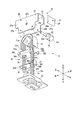
- FIG. 3 is an exploded view of a part of the tire carrier 10.
- the tire carrier 10 includes a case 11 fixed to the lower surface of the floor panel 2, a rotating shaft 12 that is supported by the case 11 and arranged along the vehicle width direction, and is housed in the case 11 and rotated.
- a chain wheel 13 that follows the shaft 12, a chain 14 that is wound around the chain wheel 13, and a hook 15 that is connected to the hanging end of the chain 14 and can lock the spare tire 9 are provided.
- the case 11 includes an upper case 20 fixed to the lower surface of the floor panel 2 and a lower case 30 fixed to the upper case 20.
- the upper case 20 includes a bracket 21 fixed to the floor panel 2 and a top cover 22 that covers the chain wheel 13 from above, left, and right.
- the bracket 21 includes a top plate 23 that extends in parallel with the floor panel 2, and a case front wall 24 and a case rear wall 25 disposed in front of and behind the chain wheel 13.
- the top plate 23 is fixed to the floor panel 2 with fastening screws or the like, and includes a top cover fixing portion 23a disposed above the chain wheel 13 and a gear box fixing portion 23b extending leftward from the top cover fixing portion 23a. It is equipped with.
- a gear box 59 is attached to the gear box fixing portion 23b.
- the case front wall 24 and the case rear wall 25 respectively extend downward from the front edge and the rear edge of the top cover fixing portion 23a.
- Lower end portions 24 a and 25 a of the case front wall 24 and the case rear wall 25 are bent in an arc shape toward the chain wheel 13.
- the lower end 24a of the case front wall 24 is an example of a stopper.
- the lower end 24a may be referred to as a stopper 24a.
- the top cover 22 includes a case upper wall 26 that is formed in a rectangular shape, and a case left wall 27 and a case right wall 28 that extend downward from the left and right edges of the case upper wall 26, respectively.
- the front and rear edges of the case upper wall 26 are fixed to the case front wall 24 and the case rear wall 25 of the bracket 21 by welding or the like, respectively.
- the case left wall 27 and the case right wall 28 face the side surface of the chain wheel 13.
- the upper sides 27 a and 28 a of the case left wall 27 and the case right wall 28 are fixed to the case front wall 24 and the case rear wall 25 of the bracket 21 by welding or the like, and face the upper side of the chain wheel 13.
- the lower sides 27b and 28b of the case left wall 27 and the case right wall 28 are formed so that the width in the front-rear direction is shorter than the upper sides 27a and 28a, and face the lower side of the chain wheel 13.
- the front edges of the upper side 27a, 28a of the case left wall 27 and the case right wall 28 protrude forward from the front edges of the lower sides 27b, 28b, and the case front wall 24 provided with the stopper 24a is placed at a predetermined position. It is fixed.
- the case front wall 24 and the case rear wall 25 of the bracket 21 and the case upper wall 26, the case left wall 27, and the case right wall 28 of the top cover 22 are fixed to each other and constitute a box 11a that opens downward. That is, the tire carrier 10 includes a box 11a that covers the upper side (floor panel 2 side) of the chain wheel 13, and the stopper 24a is provided at the lower end of the front wall (case front wall 24) of the box 11a.
- the lower case 30 includes an under cover 31 fixed to the top cover 22, a guide plate 32 fixed to the lower surface of the under cover 31, and a guide arch 33 that surrounds the chain wheel 13 from the front, upper, and rear. .
- the under cover 31 houses the chain wheel 13 together with the top cover 22.
- FIG. 4 is an exploded view of a part of the tire carrier 10.
- the under cover 31 includes a rectangular case lower wall 34, and a left side flange portion 35 a, a right side flange portion 35 b, and a rear side that stand up from the left edge right edge and rear edge of the case lower wall 34. And a collar portion 35c.
- the case lower wall 34 is disposed so as to block the lower edge of the case left wall 27 and the case right wall 28 of the top cover 22.
- a notch 34 a that is greatly cut out in a U shape from the front edge toward the rear is formed.
- a through-hole 34b penetrating in the plate thickness direction is formed.
- the starboard portion 35a and the starboard portion 35b are formed along the case left wall 27 and the case right wall 28 of the top cover 22.
- the left eaves portion 35a and the right eaves portion 35b of the under cover 31 are fixed to the lower ends of the case left wall 27 and the case right wall 28 of the top cover 22 by fastening screws or the like.
- the guide plate 32 includes a rectangular flat plate portion 36 that extends along the case lower wall 34 of the under cover 31 and a front flange portion 37 that stands up from the front edge of the flat plate portion 36.
- First and second chain guide holes 41 and 42 are formed on the front side and the rear side of the flat plate portion 36, respectively.
- the first and second chain guide holes 41 and 42 are formed in a cross shape extending in the front-rear and left-right directions.
- the first chain guide hole 41 is an example of a chain guide hole.
- the vicinity of the left and right ends of the first chain guide hole 41 may be referred to as narrow portions 36a and 36b.
- a pair of notches 44a and 44b cut out in a V shape from the left and right edges toward the first chain guide hole 41 are formed in the narrow portions 36a and 36b of the flat plate portion 36, respectively. .
- the notches 44a and 44b are examples of fragile portions, and are designed such that the guide plate 32 is broken in a state where an external force exceeding a predetermined value is applied to the chain 14 in the direction in which the spare tire 9 is pushed forward.
- the external force of the predetermined value is designed to be smaller than the external force that breaks the chain 14.
- the front side of the line passing through the notches 44a and 44b is the movable portion 36c, and the rear side is the fixed portion 36d.
- FIG. 5 is an exploded view of the lower case 30.
- the fixing portion 36 d is fixed to the case lower wall 34 of the under cover 31 by welding or the like at a location indicated by a two-dot chain line.
- the portion W1 including the movable portion 36c and the front flange portion 37 is an example of a first portion of the guide plate 32.
- the portion W2 including the fixing portion 36d is an example of a second portion of the guide plate 32.
- the notch 34a and the through hole 34b of the under cover 31 are larger than the first and second chain guide holes 41 and 42 at positions corresponding to the first and second chain guide holes 41 and 42 of the guide plate 32. Is formed.
- the bracket 21, the top cover 22, the under cover 31, and the guide plate 32 are each integrally formed by a sheet metal press or the like.
- the guide arch 33 is formed by curving a sheet metal, and has a shape (inverted U-shape) that curves into a smooth arc along a locus drawn by each vertex of the rotating chain wheel 13.
- the plate thickness of the guide arch 33 is thinner than the bracket 21, the top cover 22, the under cover 31 and the guide plate 32, and an external force exceeding the predetermined value is applied to the chain 14 in the direction in which the spare tire 9 is pushed forward. It is designed to be deformed in the state where it is damaged.
- One end (front lower end) 33a of the guide arch 33 is fixed to the front flange portion 37 of the guide plate 32 by welding or the like.
- the other end (rear lower end) 33b of the guide arch 33 is fixed to the rear collar portion 35c of the under cover 31 by welding or the like.
- bearing holes 27c and 28c for supporting the rotary shaft 12 penetrating in the vehicle width direction are formed in the case left wall 27 and the case right wall 28 of the top cover 22, respectively.
- a round bar-shaped fuse pin 51 is provided in the vicinity of the bearing hole 27c of the case left wall 27, .
- the fuse pin 51 is designed to be broken so that the external force exceeding the predetermined value is applied to the chain 14 in the direction in which the spare tire 9 is pushed forward.
- the rotary shaft 12 has a distal end 12a inserted through the bearing holes 27c and 28c of the top cover 22 and a proximal end 12b opposite to the distal end 12a.
- An eccentric cam 53 is formed at the tip 12a.
- the base end 12b is connected to the gear box 59 shown in FIG.
- the gear box 59 incorporates a bevel gear or the like that penetrates the floor panel 2, and transmits a turning operation from the vehicle interior to the rotating shaft 12.
- the chain wheel 13 has an outer shape in which large and small square columns are alternately stacked by 45 °.
- the outer peripheral surface 13 a of the chain wheel 13 is formed so as to be able to mesh with a plurality of links 14 a constituting the chain 14.
- the chain 14 is wound around the chain wheel 13 and is inserted through the first and second chain guide holes 41 and 42 of the guide plate 32.
- a hook 15 is connected to a hanging end of the chain 14 inserted through the first chain guide hole 41.
- FIG. 6 is a view of the chain wheel 13 as viewed from the left side.
- the chain wheel 13 incorporates a planetary gear 54 that engages with the eccentric cam 53 of the rotating shaft 12 and an internal gear 55 that meshes with the planetary gear 54.
- a flange 57 protruding in the radial direction of the chain wheel 13 is provided at the left end of the planetary gear 54.
- a fuse pin 51 of the top cover 22 is fitted in a groove 57 a provided in the flange 57. Since the flange 57 swings around the fuse pin 51 as a fulcrum, the planetary gear 54 can revolve (eccentric motion) about the axis X1 of the rotary shaft 12. On the other hand, since the movement is restricted by the fuse pin 51, the planetary gear 54 cannot rotate (rotate) around the axis X ⁇ b> 2 of the eccentric cam 53.
- the planetary gear 54 can rotate about the axis X2 of the eccentric cam 53, and the chain wheel 13 can rotate in the reverse direction.
- the fuse pin 51 is an example of lock-free means.
- FIG. 7 is a cross-sectional view of the tire carrier 10 cut along F7-F7 in FIG.
- a solid line indicates a normal state
- a two-dot chain line indicates a state in which the vehicle 1 is collided with another vehicle from the rear.
- FIG. 8 is a continuation of FIG.
- FIG. 9 is a perspective view of the guide plate 32 shown in FIG. 8 as viewed from the lower right, and is a view in which the case right wall of the top cover 22 is cut away. 7 and 8 is an example of a direction in which the spare tire 9 is pushed forward.
- the cross member 4 (shown in FIG. 2) arranged in front of the tire carrier 10 regulates the movement of the spare tire 9.
- the spare tire 9 is elastically deformed and the advance of the spare tire 9 does not stop immediately, and tension in the direction indicated by the arrow Z is applied to the chain 14 as shown in FIG.
- the notches 44a and 44b break the guide plate 32 so that the first portion W1 and the second portion W2 are separated from each other.
- An opening space 41a is defined between the first portion W1 and the second portion W2 that are separated from each other.
- the chain 14 is not restricted by the chain guide hole 41, and can move within the wide open space 41a.
- the direction in which the chain 14 is moved by the spare tire 9 and the chain 14 is rewound coincides with the direction Z in which the spare tire 9 is pushed forward.
- the guide arch 33 is deformed in a direction in which one end 33a fixed to the first portion W1 of the guide plate 32 is separated from the second portion W2. Thereafter, the deformation of the guide arch 33 is restricted by the first portion W1 coming into contact with the stopper 24a of the case front wall 24.
- the inner side surface 33a near the one end 33a is inclined along the direction Z in which the spare tire 9 is pushed forward.
- the inner side surface 33c may be referred to as a guide surface 33c.
- the notches 44a and 44b are first formed as shown in FIG.
- the guide plate 32 is broken so that the portion W1 and the second portion W2 are separated from each other.
- the chain 14 that is pulled back by the spare tire 9 passes through the open space 41a between the separated first portion W1 and second portion W2. Since the chain 14 is not entangled with the first chain guide hole 41, the chain 14 can be prevented from being unwound and the chain 14 can be prevented from being broken.
- the rotating shaft 12 of the chain wheel 13 is arranged in the vehicle width direction, and the first portion W1 and the second portion W2 are separated from each other. Therefore, the direction in which the chain 14 is rewound can be matched with the direction Z in which the spare tire 9 is pushed forward, and the chain 14 can be smoothly rewound to prevent the chain 14 from being broken.
- the guide arch 33 since the deformation of the guide arch 33 is defined by the stopper 24a, as shown in FIG. 8, the guide is guided along the direction in which the chain 14 is rewound (matches the direction Z in which the spare tire 9 is pushed forward).
- the guide surface 33c of the arch 33 can be inclined. Therefore, the chain 14 can be smoothly rewound by guiding the chain 14 by the deformed guide arch 33 even in an emergency such as a rear collision.
- the tire carrier 10 of the second to fourth embodiments will be described.
- symbol considers description of 1st Embodiment corresponding, and abbreviate
- the configuration other than that described below is the same as that of the first embodiment.
- the tire carrier 10 of the second embodiment will be described with reference to FIG.
- the tire carrier 10 of the second embodiment is different from the first embodiment in that the guide plate 32 and the under cover 31 are integrally formed.
- the starboard portion 35a and starboard portion 35b fixed to the top cover 22 and the movable portion 36c of the flat plate portion 36 are configured to be separable.
- slits 46a and 46b are formed between the port portion 35a and starboard portion 35b and the movable portion 36c.
- the number of parts can be reduced and the structure can be simplified. Thereby, assembly costs, such as welding, can be reduced.
- the tire carrier 10 of the third embodiment will be described with reference to FIG.
- the tire carrier 10 of the second embodiment is different from the first embodiment in that a weakened portion is formed on the inner peripheral surface of the first chain guide hole 41.
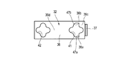
- a pair of acute angle portions 47 a and 47 b are formed at both ends of the first chain guide hole 41 in the vehicle width direction.
- options for arrangement and shape of the fragile portion can be increased, and the degree of freedom in design can be improved.
- the tire carrier 10 of the fourth embodiment will be described with reference to FIG.
- the tire carrier 10 according to the second embodiment is different from the first embodiment in that weak portions are formed on the upper surface and / or the lower surface instead of the left and right edges of the guide plate 32.
- strip-shaped thin portions 48 a and 48 b are formed on the lower surface of the guide plate 32.
- options for arrangement and shape of the fragile portion can be increased, and the degree of design freedom can be improved.
- the present invention is not limited to the above-described embodiment as it is, and can be embodied by modifying the constituent elements without departing from the scope of the invention in the implementation stage.
- various inventions can be formed by appropriately combining a plurality of components disclosed in the embodiment. For example, some components may be deleted from all the components shown in the embodiment.
- the component covering different embodiment suitably.
- the guide plate may be made of a material such as resin.
- the narrow portion of the guide plate may function as the fragile portion as it is. You may process a notch etc. similarly to other embodiment.
- the front and rear lengths of the starboard portion 35a and the starboard portion 35b may be shortened, and the left starboard portion 35a and the starboard portion 35b connected to the movable portion 36c may be omitted.
- the formation of the slits 46a and 46b can be omitted.
- the guide plate may be thinned uniformly. In this case, the narrow part of the guide plate functions as the weak part as it is.
Landscapes
- Engineering & Computer Science (AREA)
- Chemical & Material Sciences (AREA)
- Combustion & Propulsion (AREA)
- Transportation (AREA)
- Mechanical Engineering (AREA)
- Body Structure For Vehicles (AREA)
Abstract
万が一の衝突の際もガイドプレート(32)とチェーン(14)との干渉を防止できるタイヤキャリア(10)を提供する。タイヤキャリア(10)は、チェーン(14)が挿通される第1のチェーン誘導孔(41)が前側寄りに形成されたガイドプレート(32)を具備している。ガイドプレート(32)は、第1のチェーン誘導孔(41)よりもさらに前側の可動部(36c)及び前鍔部(37)と、第1のチェーン誘導孔(41)よりも後側の固定部(36d)と、切欠き(44a,44b)とを備えている。切欠き(44a,44b)は、スペアタイヤ(9)が前方に押し込まれる方向(Z)に所定値を超える外力がチェーン(14)に加わった状態において、可動部(36c)及び前鍔部(37)を含む部分(W1)と、固定部(36d)を含む部分(W2)とが離間するように、ガイドプレート(32)を破断させる。
Description
本発明は、例えば、チェーンで懸架することによりスペアタイヤを車両に保持するタイヤキャリアであって、万が一の衝突の際にチェーンの破断を防止する手段を備えたタイヤキャリアに関する。
特許文献1のスペアタイヤハンガーや特許文献2の予備タイヤ保持装置のように、スペアタイヤをチェーンで巻き上げて自動車等の車体の下部に保持させるタイヤキャリアが知られている。このようなタイヤキャリアは、例えば、スペアタイヤを係止可能なフックと、フックに連結されたチェーンと、チェーンを巻き上げるチェーンホイールと、チェーンが捩じれないようにこれを誘導するガイドプレートと、を備えている。
スペアタイヤが車体の下部に保持される場合には、スペアタイヤが車室内に収納される場合と異なり、車両が後方から衝突された際にスペアタイヤからチェーンに大きな外力が加わることがある。チェーンに過剰な外力が加わると、チェーンが破断してスペアタイヤの保持に支障が生じる可能性がある。
そこで、特許文献3に開示されるように、チェーンに大きな外力が加えられた際、チェーンの損傷を抑制する手段を備えた予備タイヤ保持装置が提案されている。
特許文献3の予備スペアタイヤ保持装置は、チェーンの損傷を抑制する手段として、衝突等の非常時にチェーンホイールが逆転することによりチェーンを巻き戻す構造となっている。しかしながら、衝突の状況によっては、チェーンホイールを収納するケースが変形してガイドプレートがチェーンと干渉することも考えられる。万が一、チェーンがガイドプレートに絡まると、チェーンの巻き戻しが阻害されてチェーンの破断を防止できなくなるおそれも考えられる。
そこで、本発明は、万が一の衝突の際にガイドプレートとチェーンとの干渉を防止できるタイヤキャリアを提供する。
本発明の実施形態は、チェーンで懸架することによりスペアタイヤを車両に保持するタイヤキャリアであって、チェーンホイールの回転軸が車両進行方向を横切る方向に配置されている。ガイドプレートがチェーンホイールの下方に配置されている。ガイドプレートの前側寄りには、チェーンが挿通されるチェーン誘導孔が形成されている。ガイドプレートは、チェーン誘導孔よりもさらに前側の第1の部分と、チェーン誘導孔よりも後側の第2の部分と、脆弱部と、を備えている。脆弱部は、スペアタイヤが前方に押し込まれる方向に所定値を超える外力がチェーンに加わった状態において、第1の部分と第2の部分とが離間するようにガイドプレートを破断させる。
この実施形態において、チェーンホイールを囲うガイドアーチと、ガイドアーチの前方に配置されたストッパと、をさらに具備してもよい。ガイドアーチは、ガイドプレートの第1の部分に固定された一端と、一端とは反対側の他端と、を有する。ストッパは、スペアタイヤが前方に押し込まれる方向に所定値を超える外力がチェーンに加わった状態において、ガイドアーチの変形を規制する。このとき、ガイドプレートの第2の部分と、ガイドアーチの他端と、がそれぞれ固定されたアンダーカバーをさらに具備してもよい。
また、脆弱部は、車両進行方向を横切る方向においてガイドプレートの外縁からチェーン誘導孔に向かう切欠きであってもよい。或いは、チェーン誘導孔の内面に形成された鋭角部であってもよい。或いは、チェーン誘導孔の近傍に形成された薄肉部であってもよい。
本発明によれば、スペアタイヤが前方に押し込まれる方向に所定値を超える外力がチェーンに加わると、脆弱部が第1の部分と第2の部分とが離間するようにガイドプレートを破断させる。巻き戻されるチェーンは、離間した第1の部分と第2の部分との間を通過する。チェーンの巻き戻しが阻害されることを回避でき、チェーンの破断を防止することができる。
以下に本発明の第1の実施形態のタイヤキャリア10について、図1から図9を参照して説明する。なお、本明細書において、外力とは、入力側(回転軸側)ではなく、出力側(スペアタイヤ側)から加えられた力をいう。チェーンホイール13の逆転とは、出力側から力を加え、チェーンホイール13を回転させることをいう。
実施形態の説明の便宜上、図1に示すように、車両1の進行方向を基準に「前(フロント)」、「後(リヤ)」、「左」及び「右」、重力を基準に「上」及び「下」を定義する。左右方向を車両1の車幅方向と呼ぶことがある。車幅方向は、進行方向を横切る方向の一例である。タイヤキャリア10は、例えば、車両1のリヤ側のフロアパネル2の下面に取り付けられる。
図2は、車両1を底面から見た図である。図2に示すように、車両1のフロアパネル2の下面には、クロスメンバ4、リヤエンドクロスメンバ5等が設けられている。クロスメンバ4は、後輪近傍で車幅方向に延びフロアパネル2の剛性を補強する。リヤエンドクロスメンバ5は、車両1の後端部で車幅方向に延び後方衝突を緩和する。タイヤキャリア10は、クロスメンバ4とリヤエンドクロスメンバ5との間に配置され、スペアタイヤ9をフロアパネル2の下面に保持している。
図3は、タイヤキャリア10の一部を分解した図である。図3に示すように、タイヤキャリア10は、フロアパネル2の下面に固定されたケース11と、ケース11に軸受けされ車幅方向に沿って配置された回転軸12と、ケース11に収納され回転軸12に従動するチェーンホイール13と、チェーンホイール13に巻き掛けられたチェーン14と、チェーン14の垂下端に連結されスペアタイヤ9を係止可能なフック15と、を備えている。
ケース11は、フロアパネル2の下面に固定されたアッパーケース20と、アッパーケース20に固定されたロアケース30と、を備えている。アッパーケース20は、フロアパネル2に固定されたブラケット21と、チェーンホイール13を上方、左方及び右方から覆うトップカバー22と、を備えている。
ブラケット21は、フロアパネル2と平行に広がる天板23と、チェーンホイール13の前後に配置されたケース前壁24及びケース後壁25と、を備えている。天板23は、フロアパネル2に締結ねじ等により固定されており、チェーンホイール13の上方に配置されたトップカバー固定部23aと、トップカバー固定部23aから左方に延びたギアボッスク固定部23bと、を備えている。ギアボックス固定部23bには、ギアボックス59が取り付けられている。
ケース前壁24及びケース後壁25は、トップカバー固定部23aの前縁及び後縁からそれぞれ下方に延びている。ケース前壁24及びケース後壁25の下端部24a,25aは、チェーンホイール13に向かって弧状に曲げられている。ケース前壁24の下端部24aは、ストッパの一例である。下端部24aをストッパ24aと呼ぶことがある。
トップカバー22は、矩形に形成されたケース上壁26と、ケース上壁26の左縁及び右縁からそれぞれ下方に延びるケース左壁27及びケース右壁28と、を備えている。ケース上壁26の前縁及び後縁は、溶接等によりブラケット21のケース前壁24及びケース後壁25にそれぞれ固定されている。ケース左壁27及びケース右壁28は、チェーンホイール13の側面と対向している。
ケース左壁27及びケース右壁28の上側27a,28aは、溶接等によりブラケット21のケース前壁24及びケース後壁25にそれぞれ固定され、チェーンホイール13の上側に対向している。ケース左壁27及びケース右壁28の下側27b,28bは、上側27a,28aよりも前後方向の幅が短くなるように形成され、チェーンホイール13の下側に対向している。
換言すると、ケース左壁27及びケース右壁28の上側27a,28aの前縁は、下側27b,28bの前縁よりも前方に突出し、ストッパ24aが設けられたケース前壁24を所定位置に固定している。
ブラケット21のケース前壁24及びケース後壁25並びにトップカバー22のケース上壁26、ケース左壁27及びケース右壁28は、互いに固定され、下方に開口したボックス11aを構成している。つまり、タイヤキャリア10は、チェーンホイール13の上側(フロアパネル2側)を覆うボックス11aを備え、ストッパ24aは、ボックス11aの前壁(ケース前壁24)の下端部に設けられている。
ロアケース30は、トップカバー22に固定されたアンダーカバー31と、アンダーカバー31の下面に固定されたガイドプレート32と、チェーンホイール13を前方、上方、後方から囲うガイドアーチ33と、を備えている。アンダーカバー31は、トップカバー22とともにチェーンホイール13を収納している。
図4は、タイヤキャリア10の一部を分解した図である。図4に示すように、アンダーカバー31は、矩形に形成されたケース下壁34と、ケース下壁34の左縁右縁及び後縁からそれぞれ起立する左鍔部35a、右鍔部35b及び後鍔部35cと、を備えている。
ケース下壁34は、トップカバー22のケース左壁27及びケース右壁28の下縁間を塞ぐように配置されている。ケース下壁34の前側には、前縁から後方に向かってU字状に大きく切り欠いた切欠き34aが形成されている。ケース下壁34の後側には、板厚方向に貫通する貫通孔34bが形成されている。
左鍔部35a及び右鍔部35bは、トップカバー22のケース左壁27及びケース右壁28に沿うように形成されている。アンダーカバー31の左鍔部35a及び右鍔部35bは、トップカバー22のケース左壁27及びケース右壁28の下端部に締結ねじ等により固定されている。
ガイドプレート32は、アンダーカバー31のケース下壁34に沿って広がる矩形の平板部36と、平板部36の前縁から起立する前鍔部37とを備えている。平板部36の前側及び後側には、第1及び第2のチェーン誘導孔41,42がそれぞれ形成されている。第1及び第2のチェーン誘導孔41,42は、前後左右方向に広がる十字状に形成されている。第1のチェーン誘導孔41は、チェーン誘導孔の一例である。
平板部36において第1のチェーン誘導孔41の左右両端近傍を幅狭部36a,36bと呼ぶことがある。平板部36の幅狭部36a,36bには、左縁及び右縁から第1のチェーン誘導孔41に向かってV字状に切り欠かれた一対の切欠き44a,44bがそれぞれ形成されている。
切欠き44a,44bは、脆弱部の一例であり、スペアタイヤ9が前方に押し込まれる方向に所定値を超える外力がチェーン14に加わった状態においてガイドプレート32が破断するように設計されている。所定値の外力は、チェーン14を破断させる外力よりも小さく設計されている。平板部36のうち、切欠き44a,44bを通る線よりも前側を可動部36c、後側を固定部36dとする。
図5は、ロアケース30を分解した図である。図5に示すように、固定部36dは、二点鎖線で示す箇所において、アンダーカバー31のケース下壁34に溶接等により固定されている。可動部36c及び前鍔部37を含む部分W1は、ガイドプレート32の第1の部分の一例である。固定部36dを含む部分W2は、ガイドプレート32の第2の部分の一例である。アンダーカバー31の切欠き34a及び貫通孔34bは、ガイドプレート32の第1及び第2のチェーン誘導孔41,42に対応する位置において、第1及び第2のチェーン誘導孔41,42よりも大きく形成されている。ブラケット21、トップカバー22、アンダーカバー31及びガイドプレート32は、それぞれ板金プレス等により一体に形成されている。
ガイドアーチ33は、板金を湾曲させて形成され、回転するチェーンホイール13の各頂点が描く軌跡に沿って滑らかな円弧に湾曲する形状(逆U字)となっている。ガイドアーチ33の板厚は、ブラケット21、トップカバー22、アンダーカバー31及びガイドプレート32よりも薄く形成され、スペアタイヤ9が前方に押し込まれる方向に上記した所定値を超える外力がチェーン14に加わった状態において変形するように設計されている。
ガイドアーチ33の一端(前下端)33aは、溶接等によりガイドプレート32の前鍔部37に固定されている。ガイドアーチ33の他端(後下端)33bは、溶接等によりアンダーカバー31の後鍔部35cに固定されている。
図4に示すように、トップカバー22のケース左壁27及びケース右壁28には、車幅方向に貫通する回転軸12を支持するための軸受孔27c,28cがそれぞれ形成されている。ケース左壁27の軸受孔27c近傍には、丸棒状のヒューズピン51が設けられている。ヒューズピン51は、スペアタイヤ9が前方に押し込まれる方向に上記した所定値を超える外力がチェーン14に加わった状態において破損するように強度が設計されている。
回転軸12は、トップカバー22の軸受孔27c,28cに挿通された先端12aと、先端12aとは反対側の基端12bとを有している。先端12aには偏心カム53が形成されている。基端12bは、図3に示すギアボックス59に接続されている。ギアボックス59は、フロアパネル2を貫通するベベルギア等を内蔵し、車室内からの回動操作を回転軸12に伝達する。
チェーンホイール13は、大小大の四角柱を45°ずつ互い違いに重ねた外形を有している。チェーンホイール13の外周面13aは、チェーン14を構成する複数のリンク14aと噛合可能に形成されている。
チェーン14は、チェーンホイール13に巻き掛けられ、ガイドプレート32の第1及び第2のチェーン誘導孔41,42に挿通されている。第1のチェーン誘導孔41に挿通されたチェーン14の垂下端にフック15が連結されている。
図6は、チェーンホイール13を左側面から見た図である。図6に示すように、チェーンホイール13は、回転軸12の偏心カム53と嵌合する遊星歯車54と、遊星歯車54と噛合する内歯歯車55とを内蔵しており、回転軸12の回動操作に従動する。
遊星歯車54の左端にチェーンホイール13の径方向へ突出するフランジ57が設けられている。フランジ57に設けられた溝57aにトップカバー22のヒューズピン51が嵌合している。フランジ57がヒューズピン51を支点として揺動するため、遊星歯車54は、回転軸12の軸心X1を中心として公転(偏心運動)できる。一方、ヒューズピン51に動きを規制されているため、遊星歯車54は、偏心カム53の軸心X2を中心として自転(回転)できない。
チェーンホイール13が逆転するとき、遊星歯車54を自転させようとする力が遊星歯車54に加えられる。ヒューズピン51が破損していない状態では、遊星歯車54の自転がヒューズピン51に阻止されており、チェーンホイール13は逆転しない。ヒューズピン51、偏心カム53並びにチェーンホイール13の遊星歯車、内歯歯車及びフランジ57は、セルフロック手段の一例である。
ヒューズピン51が破損した状態では、遊星歯車54が偏心カム53の軸心X2を中心として自転可能になり、チェーンホイール13は逆転可能になる。ヒューズピン51は、ロックフリー手段の一例である。
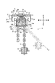
以上のように構成されたタイヤキャリア10において、後方から衝突された等の非常時における動作について、図7から図9を参照して説明する。図7は、図3中のF7-F7で切断したタイヤキャリア10の断面図である。実線は平常時の状態、二点鎖線は車両1が他の車両に後方から衝突された状態を示す。図8は、図7の続きであって後突された状態を示す図である。図9は、図8に示すガイドプレート32を右下方から見た斜視図であり、トップカバー22のケース右壁を切り欠いて示す図である。図7及び図8に矢印Zで示す方向は、スペアタイヤ9が前方に押し込まれる方向の一例である。
後突されてスペアタイヤ9が前方に押し出されると、タイヤキャリア10の前方に配置されたクロスメンバ4(図2に示す)がスペアタイヤ9の移動を規制する。しかしながら、非常に大きな力が加わるとスペアタイヤ9が弾性変形してスペアタイヤ9の前進がすぐには止まらず、図7に示すように、矢印Zで示す方向の張力がチェーン14に加えられる。
チェーン14に加えられた張力が所定値を超えたとき、ヒューズピン51が破損して、チェーンホイール13が逆転可能になる。すると、前進するスペアタイヤ9に引っ張られ、チェーン14が巻き戻される。
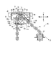
このとき、図8及び図9に示すように、切欠き44a,44bは、第1の部分W1と第2の部分W2とが離間するようにガイドプレート32を破断させる。互いに離間した第1の部分W1と第2の部分W2との間を開口空間41aとする。
チェーン14は、チェーン誘導孔41に規制されず、大きく開口した開口空間41aの範囲内で移動できる。スペアタイヤ9によりチェーン14が移動し、チェーン14が巻き戻される方向と、スペアタイヤ9が前方に押し込まれる方向Zとが一致する。
ガイドアーチ33は、ガイドプレート32の第1の部分W1に固定された一端33aが、第2の部分W2から離間する方向に変形する。その後、第1の部分W1がケース前壁24のストッパ24aと当接することにより、ガイドアーチ33の変形が規制される。変形後のガイドアーチ33では、一端33a寄りの内側面33aが、スペアタイヤ9が前方に押し込まれる方向Zに沿うように傾斜している。内側面33cを案内面33cと呼ぶことがある。
本実施形態のタイヤキャリア10によれば、スペアタイヤ9が前方に押し込まれる方向Zに所定値を超える外力がチェーン14に加わると、図9に示すように、切欠き44a,44bが第1の部分W1と第2の部分W2とが離間するようにガイドプレート32を破断させる。
スペアタイヤ9に引っ張られて巻き戻されるチェーン14は、離間した第1の部分W1と第2の部分W2との間の開口空間41aを通過する。チェーン14が第1のチェーン誘導孔41に絡まることがないため、チェーン14の巻き戻しが阻害されることを回避して、チェーン14の破断を防止することができる。
しかも、チェーンホイール13の回転軸12が車幅方向に配置され、かつ第1の部分W1と第2の部分W2との間が離間する。そのため、チェーン14が巻き戻される方向を、スペアタイヤ9が前方に押し込まれる方向Zと一致させることができ、チェーン14を円滑に巻き戻してチェーン14の破断を防止することができる。
さらに、ガイドアーチ33の変形がストッパ24aに規定されているため、図8に示すように、チェーン14が巻き戻される方向(スペアタイヤ9が前方に押し込まれる方向Zと一致)に沿うようにガイドアーチ33の案内面33cを傾斜させることができる。そのため、後突等の非常時でも変形したガイドアーチ33によりチェーン14を案内してチェーン14を円滑に巻き戻すことができる。
次に、第2から第4の実施形態のタイヤキャリア10について説明する。なお、第1の実施形態の構成と同一又は類似の機能を有する構成は、同一の符号を付して対応する第1の実施形態の記載を参酌することとし、ここでの説明を省略する。また、下記に説明する以外の構成は、第1の実施形態と同一である。
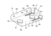
第2の実施形態のタイヤキャリア10は、図10を参照して説明する。第2の実施形態のタイヤキャリア10は、ガイドプレート32とアンダーカバー31とを一体に形成する点が第1の実施形態と異なる。第2の実施形態では、トップカバー22に固定された左鍔部35a及び右鍔部35bと、平板部36の可動部36cとを分離可能に構成する。図10に示す例では、左鍔部35a及び右鍔部35bと可動部36cとの間にスリット46a,46bを形成する。第2の実施形態では、部品点数を削減して構造を簡素化することができる。これにより、溶接等の組み立てコストを低減することができる。
第3の実施形態のタイヤキャリア10は、図11を参照して説明する。第2の実施形態のタイヤキャリア10は、第1のチェーン誘導孔41の内周面に脆弱部を形成する点が第1の実施形態と異なる。図11に示す例は、第1のチェーン誘導孔41の車幅方向両端部に一対の鋭角部47a,47bを形成する。第3の実施形態では、脆弱部について配置や形状の選択肢を増やし、設計の自由度を向上させることができる。
第4の実施形態のタイヤキャリア10は、図12を参照して説明する。第2の実施形態のタイヤキャリア10は、ガイドプレート32の左縁及び右縁ではなく、上面及び/又は下面に脆弱部を形成する点が第1の実施形態と異なる。図12に示す例は、ガイドプレート32の下面に帯状の薄肉部48a,48bを形成している。第4の実施形態では、脆弱部について配置や形状の選択肢を増やし、設計の自由度を向上させることができる。
なお、本発明は上記実施形態そのままに限定されるものではなく、実施段階ではその要旨を逸脱しない範囲で構成要素を変形して具現化できる。また、上記実施形態に開示されている複数の構成要素の適宜な組み合わせにより種々の発明を形成できる。例えば、実施形態に示される全構成要素から幾つかの構成要素を削除してもよい。更に、異なる実施形態に亘る構成要素を適宜組み合わせてもよい。例えば、ガイドプレートを樹脂等の材料から構成してもよい。ガイドプレートを板金よりも脆弱な材料から構成する場合、ガイドプレートの幅狭部をそのまま脆弱部として機能させてもよい。他の実施形態と同様に切欠き等を加工してもよい。第2の実施形態において、左鍔部35a及び右鍔部35bの前後長さを短縮し、可動部36cに連なる部分の左鍔部35a及び右鍔部35bを省略してもよい。スリット46a,46bの形成を省略することができる。第3の実施形態において、ガイドプレートを均一に薄肉化してもよい。この場合、ガイドプレートの幅狭部がそのまま脆弱部として機能する。
1…車両、9…スペアタイヤ、10…タイヤキャリア、12…回転軸、13…チェーンホイール、14…チェーン、15…フック、24a…ストッパ、31…アンダーカバー、32…ガイドプレート、33…ガイドアーチ、33a…一端、33b…他端、41…第1のチェーン誘導孔(チェーン誘導孔)、44a,44b…切欠き(脆弱部)、47a,47b…鋭角部(脆弱部)、48a,48b…薄肉部(脆弱部)、W1…第1の部分、W2…第2の部分、Z…スペアタイヤが前方に押し込まれる方向。
Claims (6)
- 車両進行方向を横切る方向に回転軸が配置されたチェーンホイールに巻き掛けたチェーンで懸架することによりスペアタイヤを車両に保持するタイヤキャリアにおいて、
前記チェーンホイールの下方に配置され、前記チェーンが挿通されるチェーン誘導孔が前側寄りに形成されたガイドプレートを具備し、
前記ガイドプレートは、
前記チェーン誘導孔よりもさらに前側の第1の部分と、
前記チェーン誘導孔よりも後側の第2の部分と、
前記スペアタイヤが前方に押し込まれる方向に所定値を超える外力が前記チェーンに加わった状態において前記第1の部分と前記第2の部分とが離間するように前記ガイドプレートを破断させる脆弱部と、
を備えたことを特徴とするタイヤキャリア。 - 請求項1に記載のタイヤキャリアにおいて、
前記第1の部分に固定された一端と、該一端とは反対側の他端と、を有し、前記チェーンホイールを囲うガイドアーチと、
前記ガイドアーチの前方に配置され、前記スペアタイヤが前方に押し込まれる方向に所定値を超える外力が前記チェーンに加わった状態において前記ガイドアーチの変形を規制するストッパと、
をさらに具備したことを特徴とするタイヤキャリア。 - 請求項2に記載のタイヤキャリアにおいて、
前記ガイドプレートの前記第2の部分と、前記ガイドアーチの前記他端と、がそれぞれ固定されたアンダーカバーをさらに具備したことを特徴とするタイヤキャリア。 - 請求項1に記載のタイヤキャリアにおいて、
前記脆弱部は、車両進行方向を横切る方向において前記ガイドプレートの外縁から前記チェーン誘導孔に向かう切欠きであることを特徴とするタイヤキャリア。 - 請求項1に記載のタイヤキャリアにおいて、
前記脆弱部は、前記チェーン誘導孔の内面に形成された鋭角部であることを特徴とするタイヤキャリア。 - 請求項1に記載のタイヤキャリアにおいて、
前記脆弱部は、前記ガイドプレートの近傍に形成された薄肉部であることを特徴とするタイヤキャリア。
Applications Claiming Priority (2)
| Application Number | Priority Date | Filing Date | Title |
|---|---|---|---|
| JP2015124829A JP6149898B2 (ja) | 2015-06-22 | 2015-06-22 | タイヤキャリア |
| JP2015-124829 | 2015-06-22 |
Publications (1)
| Publication Number | Publication Date |
|---|---|
| WO2016208235A1 true WO2016208235A1 (ja) | 2016-12-29 |
Family
ID=57584830
Family Applications (1)
| Application Number | Title | Priority Date | Filing Date |
|---|---|---|---|
| PCT/JP2016/058552 Ceased WO2016208235A1 (ja) | 2015-06-22 | 2016-03-17 | タイヤキャリア |
Country Status (2)
| Country | Link |
|---|---|
| JP (1) | JP6149898B2 (ja) |
| WO (1) | WO2016208235A1 (ja) |
Cited By (2)
| Publication number | Priority date | Publication date | Assignee | Title |
|---|---|---|---|---|
| CN106627810A (zh) * | 2017-03-09 | 2017-05-10 | 赵福星 | 一种备胎升降器 |
| CN107380274A (zh) * | 2017-08-02 | 2017-11-24 | 张俊华 | 一种钢丝绳备胎升降器总成 |
Families Citing this family (1)
| Publication number | Priority date | Publication date | Assignee | Title |
|---|---|---|---|---|
| JP6836125B2 (ja) * | 2016-09-15 | 2021-02-24 | 三菱自動車工業株式会社 | スペアタイヤ脱落防止装置 |
Citations (2)
| Publication number | Priority date | Publication date | Assignee | Title |
|---|---|---|---|---|
| JPS495860U (ja) * | 1972-04-20 | 1974-01-18 | ||
| JP2001001956A (ja) * | 1999-06-17 | 2001-01-09 | Sanko Kiki Kk | 予備タイヤ保持装置における吊り索の切断防止機構 |
-
2015
- 2015-06-22 JP JP2015124829A patent/JP6149898B2/ja not_active Expired - Fee Related
-
2016
- 2016-03-17 WO PCT/JP2016/058552 patent/WO2016208235A1/ja not_active Ceased
Patent Citations (2)
| Publication number | Priority date | Publication date | Assignee | Title |
|---|---|---|---|---|
| JPS495860U (ja) * | 1972-04-20 | 1974-01-18 | ||
| JP2001001956A (ja) * | 1999-06-17 | 2001-01-09 | Sanko Kiki Kk | 予備タイヤ保持装置における吊り索の切断防止機構 |
Cited By (2)
| Publication number | Priority date | Publication date | Assignee | Title |
|---|---|---|---|---|
| CN106627810A (zh) * | 2017-03-09 | 2017-05-10 | 赵福星 | 一种备胎升降器 |
| CN107380274A (zh) * | 2017-08-02 | 2017-11-24 | 张俊华 | 一种钢丝绳备胎升降器总成 |
Also Published As
| Publication number | Publication date |
|---|---|
| JP6149898B2 (ja) | 2017-06-21 |
| JP2017007500A (ja) | 2017-01-12 |
Similar Documents
| Publication | Publication Date | Title |
|---|---|---|
| CN105531160B (zh) | 安全带卷收器及安全带装置 | |
| JP6149898B2 (ja) | タイヤキャリア | |
| JP6076232B2 (ja) | アシストグリップ | |
| US20140306486A1 (en) | Door opening preventing apparatus for a vehicle | |
| EP3043434B1 (en) | Power feeding structure for sliding door | |
| CN1331694C (zh) | 带卷收器 | |
| WO2014013964A1 (ja) | アーム給電装置 | |
| US10029543B2 (en) | Vehicle sun visor | |
| JPWO2011007614A1 (ja) | シートベルト用リトラクタおよびシートベルト用リトラクタのスピンドル組付方法 | |
| JP2006137290A (ja) | ウエビング巻取装置 | |
| KR101987878B1 (ko) | 차량용 카고 스크린 | |
| JP2005232768A (ja) | 車両用ドアハンドル装置 | |
| JP6297809B2 (ja) | 給電装置 | |
| EP3202638B1 (en) | Steering-wheel power generation device | |
| JP6412768B2 (ja) | タイヤキャリア | |
| JP2014226969A (ja) | シート巻取装置及びシート巻取部の組付方法 | |
| JP2007261392A (ja) | 車両用リトラクタブルルーフシステム | |
| EP2390149B1 (en) | Webbing take-up device | |
| JP4757619B2 (ja) | シートベルト用リトラクター | |
| JP6836125B2 (ja) | スペアタイヤ脱落防止装置 | |
| CN100590007C (zh) | 保持结构和安全带卷绕装置 | |
| JP2007261394A (ja) | 車両用ルーフロック装置 | |
| KR102596281B1 (ko) | 차량의 카고 스크린 | |
| JP2012224217A (ja) | フードステーホルダ | |
| JP7283329B2 (ja) | 乗物用サンバイザ装置 |
Legal Events
| Date | Code | Title | Description |
|---|---|---|---|
| 121 | Ep: the epo has been informed by wipo that ep was designated in this application |
Ref document number: 16814006 Country of ref document: EP Kind code of ref document: A1 |
|
| NENP | Non-entry into the national phase |
Ref country code: DE |
|
| 122 | Ep: pct application non-entry in european phase |
Ref document number: 16814006 Country of ref document: EP Kind code of ref document: A1 |