WO2016203727A1 - Medical image processing apparatus, medical image processing method, and medical observation system - Google Patents
Medical image processing apparatus, medical image processing method, and medical observation system Download PDFInfo
- Publication number
- WO2016203727A1 WO2016203727A1 PCT/JP2016/002696 JP2016002696W WO2016203727A1 WO 2016203727 A1 WO2016203727 A1 WO 2016203727A1 JP 2016002696 W JP2016002696 W JP 2016002696W WO 2016203727 A1 WO2016203727 A1 WO 2016203727A1
- Authority
- WO
- WIPO (PCT)
- Prior art keywords
- image
- composite image
- images
- focus
- medical
- Prior art date
- Legal status (The legal status is an assumption and is not a legal conclusion. Google has not performed a legal analysis and makes no representation as to the accuracy of the status listed.)
- Ceased
Links
Images


Classifications
-
- G—PHYSICS
- G02—OPTICS
- G02B—OPTICAL ELEMENTS, SYSTEMS OR APPARATUS
- G02B21/00—Microscopes
- G02B21/36—Microscopes arranged for photographic purposes or projection purposes or digital imaging or video purposes including associated control and data processing arrangements
- G02B21/365—Control or image processing arrangements for digital or video microscopes
- G02B21/367—Control or image processing arrangements for digital or video microscopes providing an output produced by processing a plurality of individual source images, e.g. image tiling, montage, composite images, depth sectioning, image comparison
-
- A—HUMAN NECESSITIES
- A61—MEDICAL OR VETERINARY SCIENCE; HYGIENE
- A61B—DIAGNOSIS; SURGERY; IDENTIFICATION
- A61B1/00—Instruments for performing medical examinations of the interior of cavities or tubes of the body by visual or photographical inspection, e.g. endoscopes; Illuminating arrangements therefor
- A61B1/00002—Operational features of endoscopes
- A61B1/00004—Operational features of endoscopes characterised by electronic signal processing
- A61B1/00009—Operational features of endoscopes characterised by electronic signal processing of image signals during a use of endoscope
- A61B1/000094—Operational features of endoscopes characterised by electronic signal processing of image signals during a use of endoscope extracting biological structures
-
- A—HUMAN NECESSITIES
- A61—MEDICAL OR VETERINARY SCIENCE; HYGIENE
- A61B—DIAGNOSIS; SURGERY; IDENTIFICATION
- A61B1/00—Instruments for performing medical examinations of the interior of cavities or tubes of the body by visual or photographical inspection, e.g. endoscopes; Illuminating arrangements therefor
- A61B1/00002—Operational features of endoscopes
- A61B1/00004—Operational features of endoscopes characterised by electronic signal processing
- A61B1/00009—Operational features of endoscopes characterised by electronic signal processing of image signals during a use of endoscope
- A61B1/000095—Operational features of endoscopes characterised by electronic signal processing of image signals during a use of endoscope for image enhancement
-
- G—PHYSICS
- G02—OPTICS
- G02B—OPTICAL ELEMENTS, SYSTEMS OR APPARATUS
- G02B27/00—Optical systems or apparatus not provided for by any of the groups G02B1/00 - G02B26/00, G02B30/00
- G02B27/0075—Optical systems or apparatus not provided for by any of the groups G02B1/00 - G02B26/00, G02B30/00 with means for altering, e.g. increasing, the depth of field or depth of focus
-
- H—ELECTRICITY
- H04—ELECTRIC COMMUNICATION TECHNIQUE
- H04N—PICTORIAL COMMUNICATION, e.g. TELEVISION
- H04N23/00—Cameras or camera modules comprising electronic image sensors; Control thereof
- H04N23/50—Constructional details
- H04N23/555—Constructional details for picking-up images in sites, inaccessible due to their dimensions or hazardous conditions, e.g. endoscopes or borescopes
-
- H—ELECTRICITY
- H04—ELECTRIC COMMUNICATION TECHNIQUE
- H04N—PICTORIAL COMMUNICATION, e.g. TELEVISION
- H04N23/00—Cameras or camera modules comprising electronic image sensors; Control thereof
- H04N23/60—Control of cameras or camera modules
- H04N23/63—Control of cameras or camera modules by using electronic viewfinders
-
- H—ELECTRICITY
- H04—ELECTRIC COMMUNICATION TECHNIQUE
- H04N—PICTORIAL COMMUNICATION, e.g. TELEVISION
- H04N23/00—Cameras or camera modules comprising electronic image sensors; Control thereof
- H04N23/60—Control of cameras or camera modules
- H04N23/67—Focus control based on electronic image sensor signals
- H04N23/673—Focus control based on electronic image sensor signals based on contrast or high frequency components of image signals, e.g. hill climbing method
-
- H—ELECTRICITY
- H04—ELECTRIC COMMUNICATION TECHNIQUE
- H04N—PICTORIAL COMMUNICATION, e.g. TELEVISION
- H04N23/00—Cameras or camera modules comprising electronic image sensors; Control thereof
- H04N23/60—Control of cameras or camera modules
- H04N23/67—Focus control based on electronic image sensor signals
- H04N23/675—Focus control based on electronic image sensor signals comprising setting of focusing regions
-
- H—ELECTRICITY
- H04—ELECTRIC COMMUNICATION TECHNIQUE
- H04N—PICTORIAL COMMUNICATION, e.g. TELEVISION
- H04N23/00—Cameras or camera modules comprising electronic image sensors; Control thereof
- H04N23/60—Control of cameras or camera modules
- H04N23/67—Focus control based on electronic image sensor signals
- H04N23/676—Bracketing for image capture at varying focusing conditions
-
- H—ELECTRICITY
- H04—ELECTRIC COMMUNICATION TECHNIQUE
- H04N—PICTORIAL COMMUNICATION, e.g. TELEVISION
- H04N23/00—Cameras or camera modules comprising electronic image sensors; Control thereof
- H04N23/60—Control of cameras or camera modules
- H04N23/68—Control of cameras or camera modules for stable pick-up of the scene, e.g. compensating for camera body vibrations
- H04N23/681—Motion detection
- H04N23/6811—Motion detection based on the image signal
-
- H—ELECTRICITY
- H04—ELECTRIC COMMUNICATION TECHNIQUE
- H04N—PICTORIAL COMMUNICATION, e.g. TELEVISION
- H04N23/00—Cameras or camera modules comprising electronic image sensors; Control thereof
- H04N23/60—Control of cameras or camera modules
- H04N23/68—Control of cameras or camera modules for stable pick-up of the scene, e.g. compensating for camera body vibrations
- H04N23/682—Vibration or motion blur correction
- H04N23/683—Vibration or motion blur correction performed by a processor, e.g. controlling the readout of an image memory
-
- H—ELECTRICITY
- H04—ELECTRIC COMMUNICATION TECHNIQUE
- H04N—PICTORIAL COMMUNICATION, e.g. TELEVISION
- H04N23/00—Cameras or camera modules comprising electronic image sensors; Control thereof
- H04N23/70—Circuitry for compensating brightness variation in the scene
- H04N23/743—Bracketing, i.e. taking a series of images with varying exposure conditions
-
- H—ELECTRICITY
- H04—ELECTRIC COMMUNICATION TECHNIQUE
- H04N—PICTORIAL COMMUNICATION, e.g. TELEVISION
- H04N23/00—Cameras or camera modules comprising electronic image sensors; Control thereof
- H04N23/95—Computational photography systems, e.g. light-field imaging systems
- H04N23/958—Computational photography systems, e.g. light-field imaging systems for extended depth of field imaging
- H04N23/959—Computational photography systems, e.g. light-field imaging systems for extended depth of field imaging by adjusting depth of field during image capture, e.g. maximising or setting range based on scene characteristics
-
- A—HUMAN NECESSITIES
- A61—MEDICAL OR VETERINARY SCIENCE; HYGIENE
- A61B—DIAGNOSIS; SURGERY; IDENTIFICATION
- A61B1/00—Instruments for performing medical examinations of the interior of cavities or tubes of the body by visual or photographical inspection, e.g. endoscopes; Illuminating arrangements therefor
- A61B1/00163—Optical arrangements
- A61B1/00188—Optical arrangements with focusing or zooming features
-
- A—HUMAN NECESSITIES
- A61—MEDICAL OR VETERINARY SCIENCE; HYGIENE
- A61B—DIAGNOSIS; SURGERY; IDENTIFICATION
- A61B1/00—Instruments for performing medical examinations of the interior of cavities or tubes of the body by visual or photographical inspection, e.g. endoscopes; Illuminating arrangements therefor
- A61B1/04—Instruments for performing medical examinations of the interior of cavities or tubes of the body by visual or photographical inspection, e.g. endoscopes; Illuminating arrangements therefor combined with photographic or television appliances
-
- A—HUMAN NECESSITIES
- A61—MEDICAL OR VETERINARY SCIENCE; HYGIENE
- A61B—DIAGNOSIS; SURGERY; IDENTIFICATION
- A61B1/00—Instruments for performing medical examinations of the interior of cavities or tubes of the body by visual or photographical inspection, e.g. endoscopes; Illuminating arrangements therefor
- A61B1/06—Instruments for performing medical examinations of the interior of cavities or tubes of the body by visual or photographical inspection, e.g. endoscopes; Illuminating arrangements therefor with illuminating arrangements
- A61B1/0661—Endoscope light sources
- A61B1/0684—Endoscope light sources using light emitting diodes [LED]
-
- G—PHYSICS
- G02—OPTICS
- G02B—OPTICAL ELEMENTS, SYSTEMS OR APPARATUS
- G02B21/00—Microscopes
- G02B21/0004—Microscopes specially adapted for specific applications
- G02B21/0012—Surgical microscopes
Definitions
- the present technology relates to a medical image processing apparatus, a medical image processing method and a medical observation system, particularly to a medical image processing apparatus, a medical image processing method and a medical observation system by which a deep focus image can be obtained with a low delay and at a high frame rate, for example.
- a depth of field of a photographed image obtained by a medical microscope or the like is shallow, where an image of an object at a slightly different depth from a focus position (focus plane) that is in focus in a real space is blurred.
- a photographed image obtained by the medical microscope in a brain surgery for example, a frontward object is photographed in the periphery while an object (such as a surgical site) being a focus of attention located more or less at the back is photographed at the center.
- the object in the periphery of the photographed image is blurred when a focus is adjusted to bring the object at the center of the photographed image into focus, which may affect observability of the object and operability of the medical microscope.
- a real-time all-in-focus microscopic camera which performs high-speed photographing of an image while changing a focus position (focal length) and obtains a deep focus image (an all-in-focus image) from a plurality of images obtained by the photographing (refer to Patent Literature 1, for example).
- an image is to be provided to a user such as a doctor performing an operation with medical equipment such as the medical microscope, it is desirable from the nature of the medical field that the image is provided with a low delay and at a high frame rate.
- a medical image processing apparatus includes circuitry configured to generate a composite image by compositing a plurality of images obtained by capturing with a medical imaging device a living body while changing a focus position, and switch output between the generated composite image and one of the plurality of images based on a result of analysis performed on at least one of the plurality of images.
- a medical image processing method includes generating a composite image by compositing a plurality of images obtained by capturing with a medical imaging device a living body while changing a focus position, and switching output between the generated composite image and one of the plurality of images based on a result of analysis performed on at least one of the plurality of images
- a medical observation system includes a medical imaging device configured to capture a plurality of images of a living body while changing a focus position, and circuitry configured to generate a composite image by compositing the plurality of images captured by the medical imaging device, and switch output between the generated composite image and one of the plurality of images based on a result of analysis performed on at least one of the plurality of images.
- the medical image processing apparatus and the medical observation system may be independent apparatus and system or an internal block making up a single apparatus.
- the deep focus image can be obtained with the low delay and at the high frame rate, for example.
- Fig. 1 is a block diagram illustrating a configuration example of an embodiment of a medical observation system to which the present technology is applied.
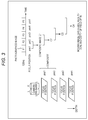
- Fig. 2 is a block diagram illustrating a first configuration example of a signal processing device 12.
- Fig. 3 is a diagram illustrating an overview of photographing performed to obtain a photographed image in a photographing unit 11 and generating a composite image in the signal processing device 12.
- Fig. 4 is a diagram illustrating an example of processing performed by an alignment unit 32 and a composition unit 33.
- Fig. 5 is a diagram illustrating a photographed image that is photographed while changing a focus position in the photographing unit 11.
- Fig. 6 is a flowchart illustrating a first operational example of the medical observation system.
- Fig. 1 is a block diagram illustrating a configuration example of an embodiment of a medical observation system to which the present technology is applied.
- Fig. 2 is a block diagram illustrating a first configuration example of a signal processing device 12.
- Fig. 3 is a
- FIG. 7 is a flowchart illustrating a second operational example of the medical observation system.
- Fig. 8 is a flowchart illustrating a third operational example of the medical observation system.
- Fig. 9 is a block diagram illustrating a second configuration example of the signal processing device 12.
- Fig. 10 is a diagram illustrating an example of setting a focus shift range in a range setting unit 62.
- Fig. 11 is a flowchart illustrating a fourth operational example of the medical observation system.
- Fig. 12 is a block diagram illustrating a third configuration example of the signal processing device 12.
- Fig. 13 is a graph illustrating an example of a relationship between a focus position and a focus score.
- Fig. 14 is a flowchart illustrating a fifth operational example of the medical observation system.
- Fig. 14 is a flowchart illustrating a fifth operational example of the medical observation system.
- Fig. 15 is a block diagram illustrating a fourth configuration example of the signal processing device 12.
- Fig. 16 is a flowchart illustrating an example of processing that sets an AF frame in the signal processing device 12.
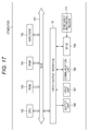
- Fig. 17 is a block diagram illustrating a configuration example of an embodiment of a computer to which the present technology is applied.
- Fig. 1 is a block diagram illustrating a configuration example of an embodiment of a medical observation system to which the present technology is applied.
- the medical observation system illustrated in Fig. 1 can be applied to medical equipment such as a medical endoscope system or a medical electron microscope (surgical microscope) that has a function of observing a living body.
- medical equipment such as a medical endoscope system or a medical electron microscope (surgical microscope) that has a function of observing a living body.
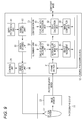
- the medical observation system includes a photographing unit 11, a signal processing device 12, and a display device 13.
- the photographing unit 11 illuminates and photographs an object being a living body such as a surgical site of a human body subjected to an operation, for example, and supplies a photographed image being an image of the living body obtained by the photographing to the signal processing device 12.
- the photographing unit 11 includes a light source 21, an optical system 22 and an image sensor 23.
- the light source 21 is formed of a Light Emitting Diode (LED) or the like and emits light illuminating the object.
- LED Light Emitting Diode
- the optical system 22 is provided in a lens barrel (not shown) and formed of optical components such as a focus lens and a diaphragm.
- the optical system 22 condenses object light (reflected light) that is the light emitted from the light source 21, reflected off of the object and incident on the optical system onto the image sensor 23.
- the image sensor 23 is a Complementary Metal Oxide Semiconductor (CMOS) sensor, for example, which receives the object light from the optical system 22, performs photoelectric conversion and photographs the object. A photographed image of the object photographed by the image sensor 23 is supplied to the signal processing device 12.
- CMOS Complementary Metal Oxide Semiconductor
- the photographing unit 11 can photograph, as the photographed image, a two-dimension (2D) image and a 3D image formed of a left eye image (Left (L) image) and a right eye image (Right (R) image).
- the photographing unit 11 When photographing the 3D image, the photographing unit 11 is provided with the optical system 22 and the image sensor 23 used to photograph the L image, and the optical system 22 and the image sensor 23 used to photograph the R image as indicated with a dotted line in the drawing.
- the signal processing device 12 performs similar processing on each of the L image and the R image, for example.
- the photographing unit 11 photographs the 2D image as the photographed image.
- the signal processing device 12 performs appropriate signal processing on the photographed image obtained from the photographing unit 11 and supplies an image obtained as a result of the signal processing to the display device 13.
- the signal processing device 12 controls the photographing unit 11 as appropriate.
- the signal processing device 12 controls the light source 21 to control intensity of the illumination provided by the light source 21, for example.
- the signal processing device 12 also controls the optical system 22 to adjust the diaphragm, a focus (position) and a zoom, for example.
- the signal processing device 12 controls the image sensor 23 to control a frame rate of a photographed image and exposure time (shutter speed) in photographing to obtain a photographed image, for example.
- the display device 13 displays the image supplied from the signal processing device 12.
- the display device 13 can be a display integral with the signal processing device 12, a stationary display provided separately from the signal processing device 12, or a head mount display, for example.
- Fig. 2 is a block diagram illustrating a first configuration example of the signal processing device 12 in Fig. 1.
- the signal processing device 12 includes a frame buffer 31, an alignment unit 32, a composition unit 33, a drive control unit 34 and a control unit 35.
- a photographed image from the photographing unit 11 (specifically the image sensor 23 thereof) and a composite image (to be described) from the composition unit 33 are supplied to the frame buffer 31.
- the frame buffer 31 temporarily stores the photographed image from the photographing unit 11 and the composite image from the composition unit 33.
- the photographing unit 11 performs (high-speed) photographing at a frame rate higher than or equal to a frame rate of the image displayed in the display device 13 to obtain the photographed image while changing a focus position with the optical system 22 controlled by the drive control unit 34 to be described.
- the alignment unit 32 performs alignment between the last composite image and the latest photographed image stored in the frame buffer 31 and supplies the aligned composite image and photographed image to the composition unit 33.
- the alignment unit 32 includes an angle-of-view adjustment unit 41, a motion blur elimination unit 42, and an object alignment unit 43.
- the angle-of-view adjustment unit 41 adjusts an angle of view of each of the composite image and the photographed image, and supplies the composite image and the photographed image after adjusting the angle of view thereof to the motion blur elimination unit 42.
- the motion blur elimination unit 42 eliminates motion blur in the photographed image supplied from the angle-of-view adjustment unit 41, and supplies the photographed image from which the motion blur is eliminated to the object alignment unit 43 along with the composite image.
- the object alignment unit 43 detects motion in the composite image and the photographed image supplied from the motion blur elimination unit 42 and, on the basis of a result of the motion detection, performs alignment between the composite image and the photographed image.
- the object alignment unit 43 performs alignment to align the position of an object in the composite image with the same object in the photographed image.
- the object alignment unit 43 then supplies the aligned composite image and photographed image to the composition unit 33.
- the composition unit 33 generates a latest composite image by compositing the composite image and the photographed image supplied from the alignment unit 32 (specifically the object alignment unit 43 thereof).
- the composition unit 33 includes a feature data calculation unit 51, a peak calculation unit 52 and an image composition unit 53.
- the feature data calculation unit 51 calculates feature data (hereinafter also referred to as in-focus feature data) representing a degree of focus (being in focus) for a pixel in each of the composite image and the photographed image supplied from the alignment unit 32, and supplies the in-focus feature data to the peak calculation unit 52.
- feature data hereinafter also referred to as in-focus feature data
- the peak calculation unit 52 calculates a peak of the in-focus feature data of the pixel arranged at the same position in each of the composite image and the photographed image. That is, the peak calculation unit 52 detects the larger in-focus feature data between the in-focus feature data of the pixel arranged at the same position in each of the composite image and the photographed image, and supplies a detected result (hereinafter also referred to as a detected peak) to the image composition unit 53.
- the image composition unit 53 generates the latest composite image by compositing the composite image and the photographed image supplied from the alignment unit 32 in accordance with the detected peak supplied from the peak calculation unit 52.
- the (latest) composite image obtained in the image composition unit 53 is supplied to the frame buffer 31 and also output to the display device 13 (Fig. 1) as appropriate.
- the drive control unit 34 drives the optical system 22 to shift the focus position.
- the control unit 35 controls the entire signal processing device 12.
- Fig. 3 is a diagram illustrating an overview of photographing performed to obtain the photographed image in the photographing unit 11 and generating the composite image in the signal processing device 12.
- Fig. 3 illustrates an example where the photographing unit 11 performs photographing to obtain photographed image (frames) F1, F2, F3 and the like at the frame rate of 120 Hz.
- the focus position in obtaining the photographed image is periodically shifted to four focus positions pos1, pos2, pos3 and pos4 in each frame.
- the focus positions pos1, pos2, pos3 and pos4 are different and have relationship represented by expression pos1 ⁇ pos2 ⁇ pos3 ⁇ pos4 in Fig. 3.
- the photographing unit 11 performs photographing to obtain the photographed images F1, F2, F3 and the like while periodically changing the focus position to the focus positions pos1, pos2, pos3, and pos4 as described above.
- the photographed image F1 is an image at the focus position pos1 (image focused on the focus position pos1)
- the photographed image F2 is an image at the focus position pos2
- the photographed image F3 is an image at the focus position pos3
- a photographed image F4 is an image at the focus position pos4.
- a photographed image F5 is an image focused on the focus position pos1 and, in this manner, a photographed image from then on corresponds to an image focused on a focus position that changes periodically.
- the signal processing device 12 theoretically generates a deep focus composite image by compositing a plurality of photographed images with different focus positions such as four frames of photographed images focused on the focus positions pos1, pos2, pos3, and pos4.
- a first composition method and a second composition method can be adopted, for example, as an Extended Depth of Field (EDoF) method that generates the deep focus composite image by compositing the plurality of photographed images with different focus positions such as the photographed images focused on the focus positions pos1, pos2, pos3, and pos4.
- EDOF Extended Depth of Field
- the photographed image focused on each of the focus positions pos1 to pos3 is aligned with the photographed image focused on the focus position pos4 that is the latest photographed image among the photographed images focused on the focus positions pos1 to pos4.
- a pixel of the photographed image focused on the focus position with the maximum (peak) in-focus feature data is selected as a pixel of a composite image, whereby a composite image formed of such pixel is generated.
- the photographed image F1 at the focus position pos1 obtained first becomes the composite image as is. That composite image (last composite image) and the following photographed image F2 at the focus position pos2 are then composited.
- the last composite image is aligned with the photographed image F2 at the focus position pos2 being the latest photographed image.
- a pixel of the photographed image F2 or the composite image with the maximum (larger) in-focus feature data is selected as a pixel of a latest composite image C1, whereby the latest composite image C1 formed of such pixel is generated.
- the composite image C1 serves as the last composite image C1 where the composite image C1 and the photographed image F3 (latest photographed image) at the focus position pos3 are composited in the similar manner to generate a latest composite image C2.
- the composite image C2 serves as the last composite image C2 where the composite image C2 and the photographed image F4 at the focus position pos4 are composited in the similar manner to generate a latest composite image C3.
- a latest composite image is generated by compositing the last composite image and the latest photographed image in the second composition method.
- Each of the composite image obtained by compositing the photographed images at the focus positions pos1 to pos4 in the first composition method and the composite image C3 obtained by the second composition method is a deep focus image with the depth of field including the focus positions pos1 to pos4.
- the composite image can be obtained after the photographed images at the focus positions pos1 to pos4 are obtained.
- the four frames of photographed images at the focus positions pos1 to pos4 are subjected to the composition processing (alignment processing performed in the alignment unit 32 and composition processing performed in the composition unit 33) that generates the composite image.
- the two frames of images including the last composite image and the latest photographed image are subjected to the composition processing.
- the composition processing can be performed faster in the second composition method than in the first composition method when three or more frames of photographed images are used to generate the composite image.
- the composition processing can be performed faster so that the composite image being a deep focus image can be obtained with a low delay and at a high frame rate.
- the second composition method can be employed to be able to provide the deep focus image with the low delay and at the high frame rate.
- the composition processing can be performed in a short time to be able to obtain the deep focus image promptly even when focus drive in the photographing unit 11 is slow and takes time.
- the signal processing device 12 can generate a single frame of a composite image by compositing four frames of photographed images every time the four frames of the photographed images at the focus positions pos1, pos2, pos3, and pos4 are obtained.
- the signal processing device 12 can generate a single frame of a composite image by compositing preceding four frames of the photographed images including a latest photographed image every time the latest photographed image is obtained. In this case, there can be obtained a composite image with the depth of field that is (approximately) four times that of a photographed image at a single focus position and the frame rate of 120 Hz.
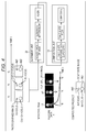
- Fig. 4 is a diagram illustrating an example of processing performed by the alignment unit 32 and the composition unit 33 illustrated in Fig. 2.
- the photographing unit 11 performs photographing to obtain the photographed image while changing the focus position as described with reference to Fig. 3.
- Fig. 4 illustrates a case where a photographed image including objects obj1 and obj2 is obtained at times t0, t1, and t2.
- Focus positions of the photographed images obtained at times t0 to t2 are different so that, in the photographed image at time t0, the object obj1 is in focus while the object obj2 is out of focus. In the photographed images obtained at times t1 and t2, the object obj1 is out of focus while the object obj2 is in focus.
- the alignment unit 32 aligns the position of the photographed image at time t0 being the last composite image with the photographed image at time t1 being the latest photographed image.
- the alignment is performed such that the identical objects in the photographed images obtained at times t0 and t1 overlap each other as much as possible.
- the angle-of-view adjustment unit 41 of the alignment unit 32 adjusts the angle of view of the photographed image at time t1 as a composite image, for example, such that the objects obj1 as well as the objects obj2 identical in the photographed images at times t0 and t1 overlap each other as much as possible.
- the angle of view is adjusted on the assumption that the photographed image at time t1 being the latest photographed image is highly correlated with the photographed image at time t0 being the last composite image, where the angle of view of the photographed image at time t0 is changed little by little to compute cross correlation or a sum total of an absolute value of a difference in pixel values as a correlation value representing correlation between the photographed images at times t0 and t1.
- the angle of view may vary slightly between one photographed image and a next photographed image due to the shift in the focus position.
- the angle of view is adjusted in order to correct such variation in the angle of view.
- the motion blur elimination unit 42 of the alignment unit 32 eliminates motion blur in the photographed image at time t1 being the latest photographed image.
- a blur kernel can possibly be the filter causing the motion blur, for example, the motion blue can be eliminated by deconvolution of the blur kernel.
- the processing of eliminating the motion blur in the motion blur elimination unit 42 can be skipped. That is, the processing of eliminating the motion blur can be skipped when the motion blur is eliminated by deconvolution of the blur kernel which, however, is not be assumed as the filter causing the blur, for example.
- the motion blur is eliminated only from the latest photographed image in this case, the motion blur can also be eliminated from the last composite image.
- the motion blur is already eliminated from the last composite image since it is obtained by compositing the deblurred photographed image and a composite image obtained before the last composite image except for a case where the photographed image serves as the last composite image as is. Therefore, the last composite image does not have to be subjected to elimination of the motion blur except for the case where the photographed image serves as the last composite image as is.
- the object alignment unit 43 of the alignment unit 32 thereafter aligns the position of an object in the photographed image at time t0 being the last composite image with the position of an object in the photographed image at time t1 being the latest photographed image.
- the object alignment unit 43 performs alignment on the assumption that the photographed image at time t1 being the latest photographed image and the photographed image at time t0 being the last composite image do not vary much (do not have a big difference) in the depth of field, namely, the identical object is in focus in both the photographed image at time t1 being the latest photographed image and the photographed image at time t0 being the last composite image.
- the object alignment unit 43 performs alignment by detecting motion between the photographed image at time t1 being the latest photographed image and the photographed image at time t0 being the last composite image pixel by pixel, for example.
- the motion detection can be performed by an arbitrary method, for example.
- the motion detection can be performed by block matching or a Kanade Lucas Tomasi (KLT) method based on a feature point, for example.
- KLT Kanade Lucas Tomasi
- a motion vector is detected pixel by pixel in the motion detection, and then the motion vector detected pixel by pixel is used to find one or a plurality of representative vectors representing motion from one or a plurality of points in the photographed image at time t0 being the last composite image to one or a plurality of points in the photographed image at time t1 being the latest photographed image.
- a projection transformation matrix that realizes projection transformation matching the motion represented by the representative vector is computed, so that the photographed image at time t0 being the last composite image is subjected to projection transformation according to the projection transformation matrix to align the position of the photographed image at time t0 being the last composite image with the photographed image at time t1 being the latest photographed image.
- the photographed image at time t0 being the last composite image and the photographed image at time t1 being the latest photographed image after the alignment are then supplied from the alignment unit 32 to the composition unit 33 and composited.
- the feature data calculation unit 51 of the composition unit 33 calculates in-focus feature data representing the degree to which a pixel is in focus in each of the photographed image at time t1 being the latest photographed image and the photographed image at time t0 being the last composite image, and supplies a feature data image having the calculated in-focus feature data as a pixel value to the peak calculation unit 52.
- the in-focus feature data can be feature data having a large value for an in-focus pixel and a small value for a blurred pixel, for example.
- Laplacian can be adopted as such in-focus feature data, for example.
- the peak calculation unit 52 refers to the feature data image from the feature data calculation unit 51 and calculates (detects) a peak of the in-focus feature data in the pixel at the identical position in each of the photographed image at time t1 being the latest photographed image and the photographed image at time t0 being the last composite image.
- Fig. 4 illustrates a pixel p1 corresponding to the object obj1 in the photographed image at time t1 being the latest photographed image and a pixel p0 corresponding to the object obj1 in the photographed image at time t0 being the last composite image and located in the position identical to the pixel p1, where the in-focus feature data of the pixel p0 corresponding to the object obj1 that is in focus is larger than the feature data of the pixel p1 corresponding to the object obj1 that is out of focus.
- the in-focus feature data of the pixel p0 is detected as the peak of the in-focus feature data of the pixels p0 and p1 at the identical position, and the detected peak being a result of the detection is supplied from the peak calculation unit 52 to the image composition unit 53.
- the image composition unit 53 generates the latest composite image by compositing the photographed image at time t1 being the latest photographed image and the photographed image at time t0 being the last composite image according to the detected peak from the peak calculation unit 52.
- the image composition unit 53 generates the latest composite image by selecting, as a pixel of the latest composite image, a pixel with the larger in-focus feature data being the detected peak, namely a pixel corresponding to the object that is more in-focus, between the pixels at the identical position in each of the photographed image at time t1 being the latest photographed image and the photographed image at time t0 being the last composite image.
- the composition unit 33 as described above composites the latest photographed image and the last composite image that are aligned by the motion detection in the alignment unit 32.
- the latest deep-focus composite image can thus be generated by following motion even when an object with some degree of motion is in the latest photographed image and the last composite image.
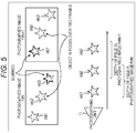
- Fig. 5 is a diagram illustrating a photographed image that is obtained while changing a focus position in the photographing unit 11.
- Fig. 5 illustrates a case where objects obj1, obj2, and obj3 arranged in a real space are photographed while changing the focus position.
- the focus position is shifted from a front side to a back side (as seen from the side of the photographing unit 11) in photographing the objects obj1 to obj3.
- Photographed images F#N and F#N+1 in Fig. 5 are adjacent frames of photographed images, where the photographed image F#N+1 is obtained after the photographed image F#N.
- the depth of field when the photographed image F#N is obtained covers the forefront object obj1 and the second forefront object obj2 but does not cover the object obj3 arranged farthest back. Therefore, the objects obj1 and obj2 are in focus while the object obj3 is out of focus in the photographed image F#N.
- the depth of field when the photographed image F#N+1 is obtained covers the second forefront object obj2 and the object obj3 arranged farthest back but does not cover the forefront object obj1. Therefore, the objects obj2 and obj3 are in focus while the object obj1 is out of focus in the photographed image F#N+1.
- the object obj2 is thus in focus in both of the photographed images F#N and F#N+1.
- the focus position is shifted such that, as described above, one or more objects (the object obj2 in Fig. 5) is/are in focus in the adjacent frames of the photographed images F#N and F#N+1, namely, the depths of field of the adjacent frames of the photographed images F#N and F#N+1 overlap in part.
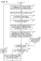
- Fig. 6 is a flowchart illustrating a first operational example of the medical observation system illustrated in Fig. 1.
- Fig. 6 illustrates an operational example of the medical observation system when the signal processing device 12 is configured as illustrated in Fig. 2.
- step S11 the control unit 35 sets a target value of the focus position to a default value such as a minimum value of a range within which the focus position can be shifted, then the operation proceeds to processing in step S12.
- step S12 the control unit 35 controls the drive control unit 34 to shift the focus position to the target value, then the operation proceeds to processing in step S13.
- step S13 the photographing unit 11 performs photographing to obtain a photographed image while the focus position is at the target value and supplies the photographed image to the frame buffer 31, then the operation proceeds to processing in step S14.
- step S14 the frame buffer 31 stores the photographed image from the photographing unit 11 as an image of interest, then the operation proceeds to processing in step S15.
- step S15 the alignment unit 32 performs alignment between the image of interest being the latest photographed image stored in the frame buffer 31 and the last composite image stored in the frame buffer 31 as described with reference to Fig. 4. Moreover, in step S15, the alignment unit 32 supplies the aligned image of interest and last composite image to the composition unit 33, then the operation proceeds to processing in step S16.
- the composite image stored in the frame buffer 31 is reset, namely deleted from the frame buffer 31, at a predetermined timing.
- the composite image is reset at the start of photographing, for example.
- the composite image is reset and not stored in the frame buffer 31.
- the composite image can also be reset in step S11 where the target value of the focus position is set to the default value, for example. Moreover, the composite image can be reset when a photographed image not suitable for generating a deep focus composite image is obtained such as when large motion is detected from the photographed image, and a composition restriction condition that restricts composition of the photographed image (and resultant generation of a composite image) is satisfied.
- steps S15 and S16 are skipped when the composite image is not stored in the frame buffer 31, in which case the image of interest is stored as the composite image into the frame buffer 31.
- step S16 as described above with reference to Fig. 4, the composition unit 33 calculates the in-focus feature data of the pixel in each of the aligned image of interest and last composite image and, according to the calculated in-focus feature data, composites the image of interest and the last composite image to generate the latest composite image.
- the composition unit 33 generates the latest composite image by selecting, as a pixel of the latest composite image, the pixel that is more in focus between the pixels in the image of interest and the last composite image according to the in-focus feature data.
- the composition unit 33 supplies the latest composite image to the frame buffer 31, which stores the latest composite image by overwriting the last composite image therewith, then the operation proceeds from the processing in step S16 to processing in step S17.
- the latest composite image stored in the frame buffer 31 as described above is used as a last composite image in step S15 performed in the next round of operation.
- step S17 the control unit 35 determines whether the target value of the focus position is set to a maximum value of the range within which the focus position can be shifted.
- step S18 proceeds to processing in step S18 when it is determined in step S17 that the target value is not set to the maximum value of the range within which the focus position can be shifted, namely when the target value is smaller than the maximum value of the range within which the focus position can be shifted.
- step S18 the control unit 35 increases the target value of the focus position by a predetermined value from the current value, then the operation returns to the processing in step S12.
- step S12 as described above, the control unit 35 controls the drive control unit 34 to shift the focus position to the target value.
- the similar processing is repeated from then on so that the photographed image is obtained while changing the focus position and that the latest photographed image and the last composite image are composited.
- step S19 the operation proceeds to processing in step S19 when it is determined in step S17 that the target value is set to the maximum value of the range within which the focus position can be shifted, namely when a plurality of photographed images is obtained while shifting the focus position across the range within which the focus position can be shifted.
- step S19 the composition unit 33 outputs the latest composite image to be displayed in the display device 13 (Fig. 1), then the operation returns to the processing in step S11.
- the plurality of photographed images is obtained while shifting the focus position across the range within which the focus position can be shifted, and then the composite image is generated by using all of the plurality of photographed images and output/displayed to/in the display device 13.
- the frame rate of the composite image displayed in the display device 13 is lower than the frame rate of the photographed image obtained in the photographing unit 11 by the amount corresponding to the number of frames of the photographed images used to generate the composite image.
- Fig. 7 is a flowchart illustrating a second operational example of the medical observation system illustrated in Fig. 1.
- Fig. 7 illustrates another operational example of the medical observation system when the signal processing device 12 is configured as illustrated in Fig. 2.
- processing similar to the processing performed in each of steps S11 to S16 of the first operational example in Fig. 6 is performed in each of steps S21 to S26.
- step S26 the composition unit 33 generates a latest composite image and supplies it to the frame buffer 31, which stores the latest composite image by overwriting the last composite image therewith, then the operation proceeds to processing in step S27.
- step S27 the composition unit 33 outputs the latest composite image to be displayed in the display device 13 (Fig. 1) as with step S19 of the first operational example in Fig. 6, then the operation proceeds to processing in step S28.
- steps S28 and S29 processing similar to the processing performed in each of steps S17 and S18 of the first operational example in Fig. 6 is performed.
- the plurality of photographed images is obtained while shifting the focus position across the range within which the focus position can be shifted, and then the composite image is generated by using all of the plurality of photographed images and output/displayed to/in the display device 13.
- a latest composite image is output/displayed to/in the display device 13 in step S27 every time the latest composite image is generated by using the latest photographed image (image of interest) in step S26 corresponding to S16 of the first operational example.
- the frame rate of the composite image displayed in the display device 13 corresponds with the frame rate of the photographed image obtained by the photographing unit 11.
- a user can perform an operation or the like to select whether to generate the composite image by using all of the plurality of photographed images obtained while shifting the focus position across the range within which it can be shifted and output the composite image to the display device 13 as described in the first operational example of Fig. 6, or to output the latest composite image to the display device 13 every time the latest composite image is generated by using the latest photographed image as described in the second operational example of Fig. 7.
- the composite image is generated by using all of the plurality of photographed images obtained while shifting the focus position across the range within which the focus position can be shifted and then output to the display device 13.
- Fig. 8 is a flowchart illustrating a third operational example of the medical observation system illustrated in Fig. 1.
- Fig. 8 illustrates yet another operational example of the medical observation system when the signal processing device 12 is configured as illustrated in Fig. 2.
- processing similar to the processing performed in each of steps S11 to S18 of the first operational example in Fig. 6 is performed in each of steps S31 to S38.
- step S37 as with the corresponding step S17 of the first operational example, the control unit 35 determines whether the target value of the focus position is set to a maximum value of the range within which the focus position can be shifted.
- step S39 the target value is set to the maximum value of the range within which the focus position can be shifted.
- step S39 the control unit 35 determines whether a composition restriction condition that restricts composition of the photographed image (and resultant generation of a composite image) is satisfied.
- the composition restriction condition can be a case where a photographed image not suitable for generating a deep focus composite image is obtained or a case where a user does not desire to obtain a deep focus image, for example.
- the photographed image not suitable for generating the deep focus composite image is obtained when, for example, reliability of the angle of view adjustment performed on the image of interest and the last composite image is less than or equal to a threshold, the angle of view adjustment being performed in the alignment between the image of interest and the last composite image in step S35.
- the reliability of the angle of view adjustment can be indicated by the correlation value between the image of interest and the last composite image when the angle of view of the last composite image is adjusted, for example.
- the photographed image not suitable for generating the deep focus composite image is obtained when, for example, reliability of the motion detection performed on the image of interest and the last composite image is less than or equal to a threshold, the motion detection being performed in compositing the image of interest and the last composite image in step S36.
- the reliability of the motion detection can be indicated by a value inversely proportional to a Sum of Absolute Difference (SAD) or the like being an evaluation value that is used to detect a motion vector in block matching performed as motion detection and evaluates similarity between blocks, for example.
- SAD Sum of Absolute Difference
- the photographed image not suitable for generating the deep focus composite image is obtained when, for example, the degree of the motion detected in the image of interest and the last composite image in the motion detection is higher than or equal to a threshold, the motion detection being performed in compositing the image of interest and the last composite image in step S36.
- the case where the degree of motion detected in the image of interest and the last composite image in the motion detection is higher than or equal to the threshold can be set as the composition restriction condition to be able to prevent generation of the aforementioned composite image with considerable motion blur.
- the user does not desire to obtain the deep focus image when, for example, a photographed image includes a living body such as a surgical site of a human body undergoing an operation as well as a treatment tool such as forceps used to perform a treatment on the surgical site where the treatment tool is intentionally moved (the treatment tool is moved toward the surgical site, for example) by the user (who operates the treatment tool).
- a living body such as a surgical site of a human body undergoing an operation as well as a treatment tool such as forceps used to perform a treatment on the surgical site where the treatment tool is intentionally moved (the treatment tool is moved toward the surgical site, for example) by the user (who operates the treatment tool).
- the user does not desire to obtain the deep focus image when, for example, a button (not shown) operated when the user does not desire to obtain the deep focus image is operated.
- step S40 The operation proceeds to processing in step S40 when it is determined in step S39 that the composition restriction condition is satisfied.
- step S40 the composition unit 33 reads from the frame buffer 31 one of the plurality of photographed images used to generate the latest composite image, namely a single frame of photographed image focused on the center or the like through the alignment unit 32.
- the composition unit 33 selects the photographed image read from the frame buffer 31 and focused on the center as the latest composite image, then the operation proceeds from the processing in step S40 to processing in step S41.
- the operation skips the processing in step S40 and proceeds to the processing in step S41 when it is determined in step S39 that the composition restriction condition is not satisfied.
- step S41 the composition unit 33 outputs the latest composite image to be displayed in the display device 13 (Fig. 1) as with step S19 of the first operational example in Fig. 6, then the operation returns to the processing in step S31.
- the composite image formed by compositing the plurality of photographed images obtained while changing the focus position is output/displayed to/in the display device 13 when the composition restriction condition is not satisfied whereas, when the composition restriction condition is satisfied, one of the plurality of photographed images is output/displayed to/in the display device 13 due to output restriction on the composite image formed by compositing the plurality of photographed images obtained while changing the focus position.
- the medical observation system being medical equipment to prevent interruption of the image displayed in the display device 13 as much as possible and keep displaying the image in the display device 13 considering the nature of the system.
- the photographed image focused on the center instead of the composite image with considerable motion blur is displayed in the display device 13 when the composition restriction condition is satisfied, namely when the composite image with the considerable motion blur caused by strong shaking of the photographing unit 11 is generated, for example.
- Fig. 9 is a block diagram illustrating a second configuration example of the signal processing device 12 in Fig. 1.
- the signal processing device 12 in Fig. 9 includes a frame buffer 31 to a control unit 35 as well as a depth estimation unit 61, a range setting unit 62 and a range storing unit 63.
- the signal processing device 12 includes the frame buffer 31 to the control unit 35.
- the signal processing device 12 in Fig. 9 is however different from that in Fig. 2 in that the depth estimation unit 61, the range setting unit 62 and the range storing unit 63 are newly provided.
- the depth estimation unit 61 estimates the depth of an object in a photographed image obtained by a photographing unit 11 and supplies a depth map in which depth information indicating the depth is registered to the range setting unit 62.
- the depth of the object can be estimated from a parallax between an L image and an R image forming a 3D image photographed by the photographing unit 11 when the photographing unit 11 is a so-called 3D camera capable of photographing a 3D image.
- the depth can also be estimated by measuring Time of Flight (ToF) with use of a laser or irradiating the object with a specific pattern such as textured light, for example.
- the depth of the object can be estimated on the basis of a state of an optical system 22 controlled by an Auto Focus (AF) function when the medical observation system of Fig. 1 is equipped with the AF function.
- AF Auto Focus
- the range setting unit 62 uses the depth map from the depth estimation unit 61 as appropriate, sets a range within which the focus position is shifted (hereinafter also referred to as a focus shift range) according to an operation of a user or the like, and supplies the range to the range storing unit 63.
- the range storing unit 63 stores the focus shift range supplied from the range setting unit 62.
- a drive control unit 34 of the signal processing device 12 in Fig. 9 shifts the focus position across the focus shift range stored in the range storing unit 63.
- the photographing unit 11 of Fig. 9 performs photographing to obtain a photographed image while changing the focus position within the focus shift range set according to the user operation.
- Fig. 10 is a diagram illustrating an example of setting the focus shift range in the range setting unit 62.
- objects obj1, obj2, and obj3 in Fig. 10 are arranged in this order toward the back in a real space.
- the focus shift range is set such that positions of the two objects obj2 and obj3 at the back among the objects obj1 to obj3 are included as the focus positions.
- the focus shift range is set to include the positions of the two objects obj2 and obj3 among the objects obj1 to obj3 as illustrated in Fig. 10, an image in which the two objects obj2 and obj3 out of the objects obj1 to obj3 are in focus is generated as a composite image.
- the focus position in obtaining the photographed image used to generate the composite image can be limited by setting the focus shift range according to the user operation as described above.
- the limitation on the focus position can reduce the number of frames of the photographed images used to generate the composite image and, as a result, a composite image to be displayed in a display device 13 can be generated at a shorter interval to be able to increase the frame rate of the composite image to a high frame rate.
- Fig. 11 is a flowchart illustrating a fourth operational example of the medical observation system illustrated in Fig. 1.
- Fig. 11 illustrates an operational example of the medical observation system when the signal processing device 12 is configured as illustrated in Fig. 9.
- the depth estimation unit 61 in step S51 estimates the depth, generates a depth map in which depth information of an object is registered and supplies the depth map to the range setting unit 62, then the operation proceeds to processing in step S52.
- step S52 the range setting unit 62 waits for a user operation or the like and, according to the operation, sets a focus shift range within which the focus position is shifted and supplies it to the range storing unit 63, then the operation proceeds to processing in step S53.
- the user can specify the focus shift range by operating a touch panel that is not shown or the like.
- the user can specify the focus shift range by inputting an absolute distance in millimeters (mm) as the minimum value and maximum value of the focus shift range, for example.
- the user can also specify the focus shift range by inputting the range toward the front and back in the depth direction from the center being the focus position (in-focus position) determined by AF, for example.
- the user can also specify the focus shift range by specifying the object in the photographed image obtained by the photographing unit 11, for example.
- the range setting unit 62 uses the depth map obtained in the depth estimation unit 61 and sets the focus shift range.
- the range setting unit 62 refers to the depth map and acknowledges a range in the depth direction where the object specified by the user is present. The range setting unit 62 then sets the range in the depth direction where the object specified by the user is present as the focus shift range.
- the range setting unit 62 sets, as the focus shift range, a range between positions corresponding to the forefront object and the object located farthest back among the plurality of objects.
- the focus shift range is set within the range the focus position can be shifted.
- the signal processing device 12 of Fig. 9 can also be configured without including the depth estimation unit 61 when the range setting unit 62 does not use the depth map in setting the focus shift range.
- step S53 the range storing unit 63 stores the focus shift range supplied from the range setting unit 62.
- the focus shift range stored in the range storing unit 63 is updated every time the user performs an operation to specify the focus shift range.
- step S53 the operation proceeds to processing in step S61, from which on the focus position is shifted across the focus shift range stored in the range storing unit 63 to obtain a photographed image and generate a composite image.
- a control unit 35 in step S61 sets a target value of the focus position to a default value such as the minimum value of the focus shift range stored in the range storing unit 63, then the operation proceeds to processing in step S62.
- steps S62 to S66 processing similar to the processing performed in each of steps S12 to S16 of the first operational example in Fig. 6 is performed.
- step S66 the control unit 35 determines whether the target value of the focus position is set to the maximum value of the focus shift range stored in the range storing unit 63.
- step S68 proceeds to processing in step S68 when it is determined in step S67 that the target value is not set to the maximum value of the focus shift range, namely when the target value is smaller than the maximum value of the focus shift range.
- step S68 of the control unit 35 in step S68 increases the target value of the focus position by a predetermined value from the current value, then the operation returns to the processing in step S62, from which on the similar processing is repeated.
- the photographed image is obtained while changing the focus position across the focus shift range set according to the user operation, and then the composite image is generated.
- step S69 the operation proceeds to processing in step S69 when it is determined in step S67 that the target value is set to the maximum value of the focus shift range, namely when a plurality of photographed images is obtained while shifting the focus position across the focus shift range.
- step S69 a composition unit 33 outputs a latest composite image to be displayed in the display device 13 (Fig. 1) as with step S19 of the first operational example in Fig. 6, then the operation returns to the processing in step S61.
- the plurality of photographed images is obtained while shifting the focus position across the focus shift range set according to the user operation, and the composite image is generated by using the plurality of photographed images.
- the time it takes to shift the focus position is reduced when the focus shift range set according to the user operation is narrower than the range within which the focus position can be shifted, whereby the frame rate of the composite image displayed in the display device 13 can be increased to a high frame rate.
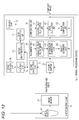
- Fig. 12 is a block diagram illustrating a third configuration example of the signal processing device 12 of Fig. 1.
- the signal processing device 12 in Fig. 12 includes a frame buffer 31 to a control unit 35 as well as a score calculation unit 71, an AF control unit 72, a buffer 73 and a peak detection unit 74.
- the signal processing device 12 includes the frame buffer 31 to the control unit 35.
- the signal processing device 12 in Fig. 12 is however different from that in Fig. 2 in that the score calculation unit 71, the AF control unit 72, the buffer 73 and the peak detection unit 74 are newly provided.
- the signal processing device 12 in Fig. 12 has an AF function.
- the score calculation unit 71 calculates a focus score that evaluates focus in a (latest) photographed image stored in the frame buffer 31.
- the focus score can be indicated by a physical quantity representing the degree of contrast in the photographed image, for example.
- a contrast AF method is employed in this case.
- the score calculation unit 71 sets an AF frame demarcating the range of the photographed image for which the focus score is calculated at a predetermined position, or at the center of the photographed image, for example. The score calculation unit 71 then uses the photographed image within the AF frame to calculate the focus score and supplies the score to the AF control unit 72 and the buffer 73.
- the AF control unit 72 controls the AF according to the focus score supplied from the score calculation unit 71.
- the AF control unit 72 determines a shift amount (including a direction) of the focus position such that the focus position is shifted to have a higher focus score, and controls the drive control unit 34 such that the focus position is shifted by the shift amount.
- the buffer 73 stores the focus score from the score calculation unit 71.
- the buffer 73 can be formed of a First In First Out (FIFO) memory with 2N+1 tiers, for example, in which case the buffer 73 can store latest 2N+1 frames of focus scores.
- FIFO First In First Out
- the peak detection unit 74 detects a peak, namely a local maximum score being a local maximum value (including the maximum value), from the focus score stored in the buffer 73 and supplies the detected local maximum score to the control unit 35.
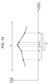
- Fig. 13 is a graph illustrating an example of a relationship between the focus position and the focus score.
- Fig. 13 illustrates an example where the focus position is shifted in the order of positions P1, P2, P3, P4, P5, and P6 by the contrast AF method and shifted to the in-focus position P6 in the end at which the focus score has the maximum value.
- the focus position is shifted to have a higher focus score until the focus position is shifted to the vicinity of the in-focus position P6.
- the focus position is shifted to straddle the in-focus position P6 (to go back and forth over the in-focus position P6) in order to detect the in-focus position P6.
- Fig. 13 illustrates the case where the focus position is first shifted to the right in the figure in the order of the positions P1, P2, and P3.
- the focus score increasing as the focus position is shifted from the position P1 to the position P2 decreases at the position P3, whereby the focus position is shifted to the left in a reverse direction from the position P3 to the position P4.
- the focus position is again shifted to the right from the position P4 to the position P5, and again to the left from the position P5 to reach the in-focus position P6.
- the signal processing device 12 in Fig. 12 detects the peak of the focus score, namely the local maximum score (not necessarily the maximum value), from the focus score and generates a composite image by using composition target images being a plurality of photographed images obtained at the focus position that is the focus position corresponding to the local maximum score and is in a predetermined range including a peak position.
- the peak of the focus score namely the local maximum score (not necessarily the maximum value)
- composition target images being a plurality of photographed images obtained at the focus position that is the focus position corresponding to the local maximum score and is in a predetermined range including a peak position.
- the focus score increasing from the position P1 to the position P2 decreases at the position P3 in Fig. 13, whereby it is detected that the focus score at the position P2 is the local maximum score and thus the position P2 is the peak position.
- the signal processing device 12 in Fig. 12 stops shifting the focus position performed as AF. Moreover, a predetermined range R including the peak position P2 that is the position P2 at which the local maximum score is detected is set as a composition target focus range R being the range of the focus position of the photographed images to be the composition target images.
- the composite image is then generated by using the composition target images being the photographed images obtained at the focus position in the composition target focus range R.
- the predetermined range R is set within the range in which the focus position can be shifted.
- a deep focus composite image can be obtained by using the photographed images obtained up until the focus position is shifted to the in-focus position P6 by the AF function.
- the focus position need only be shifted to the vicinity of the in-focus position P6, not to the in-focus position P6, in AF so that AF can be substantially increased in speed.
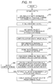
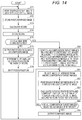
- Fig. 14 is a flowchart illustrating a fifth operational example of the medical observation system illustrated in Fig. 1.
- Fig. 14 illustrates an operational example of the medical observation system when the signal processing device 12 is configured as illustrated in Fig. 12.
- step S71 a photographing unit 11 performs photographing to obtain a photographed image and supplies the photographed image to the frame buffer 31, then the operation proceeds to processing in step S72.
- step S72 the frame buffer 31 stores the photographed image supplied from the photographing unit 11, then the operation proceeds to processing in step S73.
- step S73 the score calculation unit 71 calculates a focus score by using a photographed image within the AF frame set at a predetermined position among the (latest) photographed images stored in the frame buffer 31 and supplies the focus score to the AF control unit 72 and the buffer 73, then the operation proceeds to processing in step S74.
- step S74 the buffer 73 stores the focus score supplied from the score calculation unit 71, then the operation proceeds to processing in step S75.
- step S75 the peak detection unit 74 performs detection of a local maximum score from the focus score stored in the buffer 73 and determines whether the local maximum score is successfully detected.
- step S76 the composition unit 33 reads the latest photographed image from the frame buffer 31 through the alignment unit 32 and outputs the latest photographed image to a display device 13 as a latest composite image, then the operation proceeds to processing in step S77.
- Step S76 can be skipped here.
- step S77 the AF control unit 72 determines a shift amount of the focus position to have a higher focus score according to the focus score supplied from the score calculation unit 71, then the operation proceeds to processing in step S78.
- step S78 the AF control unit 72 controls the drive control unit 34 to shift the focus position by the shift amount determined in step S77, whereby the focus position is shifted by the shift amount determined in step S77.
- step S78 The operation thereafter returns from the processing in step S78 to step S71, and the processing in each of steps S71 to S78 is repeated until it is determined in step S75 that the local maximum score is detected.
- step S80 the operation then proceeds to processing in step S80 when it is determined in step S75 that the local maximum score is detected.
- step S80 the control unit 35 sets a predetermined range R of the focus position with the center being a peak position that is the focus position at which the local maximum score is detected as a composition target focus range R being the range of the focus position of the photographed images to be used as composition target images.
- the control unit 35 identifies 2N+1 frames of photographed images as the composition target images, the 2N+1 frames of photographed images including 2N frames of photographed images obtained at N focus positions preceding and following the peak position and a single frame of photographed image obtained at the focus position being the peak position.
- all photographed images obtained at the focus positions preceding or following the peak position can be identified as the composition target images among the photographed images obtained at the focus positions within the composition target focus range R, for example.
- the photographed images can be obtained while shifting the focus position within the composition target focus range R such that N frames of photographed images are obtained at the focus positions preceding and following the peak position.
- step S81 The operation proceeds to processing in step S81 after the composition target images are identified as described above in step S80.
- the composite image stored in the frame buffer 31 can be reset when the composition target images are identified in step S80.
- step S81 the alignment unit 32 selects, as an image of interest, one photographed image not yet selected as the image of interest from among the photographed images being the composition target images stored in the frame buffer 31, then the operation proceeds to processing in step S82.
- step S82 performs alignment between the image of interest and the last composite image stored in the frame buffer 31 and supplies the aligned image of interest and last composite image to the composition unit 33, then the operation proceeds to processing in step S83.
- steps S82 and S83 are skipped when the composite image is not stored in the frame buffer 31, in which case the image of interest is stored as the composite image into the frame buffer 31.
- the composition unit 33 in step S83 calculates in-focus feature data of a pixel in each of the aligned image of interest and last composite image and, according to the in-focus feature data, composites the image of interest and the last composite image to generate a latest composite image.
- the composition unit 33 also supplies the latest composite image to the frame buffer 31, which stores the latest composite image by overwriting the last composite image therewith, then the operation proceeds from the processing in step S83 to processing in step S84.
- step S84 the alignment unit 32 determines whether all the composition target images are selected as the images of interest.
- step S84 When it is determined in step S84 that not all the composition target images are selected as the images of interest yet, the operation returns to the processing in step S81, from which on the similar processing is repeated.
- step S85 the operation proceeds to processing in step S85 when it is determined in step S84 that all the composition target images are selected as the images of interest, or when a composite image using all the composition target images is generated as the latest composite image.
- step S85 the composition unit 33 outputs the latest composite image to be displayed in the display device 13, then the operation returns to the processing in step S71.
- the AF function can also be performed to shift the focus position until the maximum value of the focus score is detected, namely until the in-focus position is detected, for example.
- the composite image can be generated by using composition target images including a photographed image obtained at the in-focus position and photographed images obtained at a plurality of focus positions preceding and following the in-focus position.
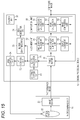
- Fig. 15 is a block diagram illustrating a fourth configuration example of the signal processing device 12 in Fig. 1.
- the signal processing device 12 in Fig. 15 includes a frame buffer 31 to a control unit 35, a score calculation unit 71 to a peak detection unit 74, and an AF frame setting unit 81.
- the signal processing device 12 includes the frame buffer 31 to the control unit 35 as well as the score calculation unit 71 to the peak detection unit 74.
- the signal processing device 12 in Fig. 15 is however different from that in Fig. 12 in that the AF frame setting unit 81 is newly provided.
- the signal processing device 12 in Fig. 15 has an AF function as is the case with the example in Fig. 12.
- an AF frame is set at a predetermined position such as the center of a photographed image in the example illustrated in Fig. 12 whereas, in the example illustrated in Fig. 15, the signal processing device can set an AF frame at a position specified by a user in a photographed image.
- the AF frame setting unit 81 sets the AF frame according to an AF mode and supplies it to the score calculation unit 71.
- the score calculation unit 71 calculates a focus score by using the photographed image within the AF frame supplied from the AF frame setting unit 81.
- the AF mode includes a normal mode and a specification mode.
- the AF mode is set to the normal mode or the specification mode according to an operation of a user, for example.
- the AF frame setting unit 81 sets the AF frame at a default position, namely at a predetermined position such as the center of the photographed image.
- the AF frame setting unit 81 sets the AF frame at a position specified by the user on a photographed image according to an operation of the user.
- the AF frame setting unit 81 sets the AF frame at the edge position.
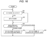
- Fig. 16 is a flowchart illustrating an example of processing that sets the AF frame in the signal processing device 12 of Fig. 15.
- step S91 the AF frame setting unit 81 determines whether a selection operation of selecting the AF mode is performed by the user.
- step S91 When it is determined in step S91 that the selection operation of selecting the AF mode is performed by the user, the operation proceeds to processing in step S92, in which the AF frame setting unit 81 sets (changes) the AF mode to the normal mode or specification mode according to the selection operation by the user, then the operation proceeds to processing in step S93.
- the operation skips the processing in step S92 and proceeds to the processing in step S93 when it is determined in step S91 that the selection operation of selecting the AF mode is not performed by the user.
- step S93 the AF frame setting unit 81 determines the (current) AF mode.
- step S93 When it is determined in step S93 that the AF mode is set to the normal mode, the operation proceeds to processing in step S94, in which the AF frame setting unit 81 sets the AF frame at the center of the photographed image or the like as a default position, then the operation returns to the processing in step S91.
- step S93 When it is determined in step S93 that the AF mode is set to the specification mode, the operation proceeds to processing in step S95 where the AF frame setting unit waits for the user to perform a specification operation of specifying the AF frame and sets the AF frame at a position on the photographed image specified by the specification operation, then the operation returns to the processing in step S91.
- the specification operation can be performed by touching the position on the photographed image displayed in a display device 13, for example.
- the present technology can be applied not only to an image obtained by photographing a human body but also an image obtained by photographing a living body other than the human body.
- the present technology can also be applied to an image obtained by photographing an object other than the living body.
- the present technology can be applied to an arbitrary device with a photographing function other than medical equipment such as a digital camera, a vehicle-mounted image sensor, a surveillance camera installed for surveillance and security of agricultural products, and an industrial endoscope (fiberscope) system.
- a photographing function other than medical equipment such as a digital camera, a vehicle-mounted image sensor, a surveillance camera installed for surveillance and security of agricultural products, and an industrial endoscope (fiberscope) system.
- the present technology can be applied to an image photographed by a device photographing visible light as well as an image photographed by a device photographing non-visible light (electromagnetic wave).
- the series of processings performed by the signal processing device 12 can be implemented by hardware or software.
- a program configuring the software is installed on a general-purpose computer or the like.
- FIG. 17 illustrates a configuration example of an embodiment of a computer installed with the program implementing the series of processings.
- the program can be recorded beforehand in a hard disk 105 or a ROM 103 being a recording medium built into the computer.
- the program can be stored (recorded) in a removable recording medium 111.
- the removable recording medium 111 can then be provided as so-called packaged software.
- the removable recording medium 111 can be a flexible disk, a Compact Disc Read Only Memory (CD-ROM), a Magneto Optical (MO) disk, a Digital Versatile Disc (DVD), a magnetic disk, or a semiconductor memory, for example.
- the program can be installed on the computer from the removable recording medium 111 or downloaded to the computer via a communication network or broadcast network and installed on the built-in hard disk 105.
- the program can be transmitted by radio from a download site to the computer via a satellite used for digital satellite broadcast or transmitted to the computer in a wired manner via a network such as a Local Area Network (LAN) or the Internet, for example.
- LAN Local Area Network
- a Central Processing Unit (CPU) 102 is incorporated into the computer and connected to an input/output interface 110 through a bus 101.
- the CPU 102 runs a program stored in the Read Only Memory (ROM) 103 according to the command.
- the CPU 102 runs a program stored in the hard disk 105 by loading it to a Random Access Memory (RAM) 104.
- RAM Random Access Memory
- the CPU 102 then performs the processing according to the aforementioned flowchart or the processing performed by the configuration illustrated in the aforementioned block diagram. Then, the CPU 102 for example outputs or transmits the processing result from an output unit 106 or a communication unit 108 through the input/output interface 110 and records the result in the hard disk 105 as needed.
- the input unit 107 is formed of a keyboard, a mouse, a microphone and the like.
- the output unit 106 is formed of a Liquid Crystal Display (LCD), a speaker and the like.
- LCD Liquid Crystal Display
- the processing performed by the computer according to the program does not have to be performed in time series in the order described in the flowchart.
- the processing performed by the computer according to the program includes processing performed in parallel or individually (such as parallel processing or processing by an object).
- the program may be processed by a single computer (processor) or processed in a distributed manner by a plurality of computers.
- the program may also be transferred to a remote computer and run.
- the system refers to the assembly of a plurality of components (such as devices and modules (parts)) where it does not matter whether or not all the components are housed in the same housing. Accordingly, a plurality of devices housed in separate housings and connected through a network as well as a device with a plurality of modules housed in a single housing are both systems.
- the present technology can for example employ cloud computing in which a single function is shared and processed collaboratively among a plurality of devices through a network.
- each step described in the aforementioned flowcharts can be performed by a single device or can be shared and performed by a plurality of devices.
- the plurality of processings included in the single step can be performed by a single device or can be shared and performed by a plurality of devices.
- a medical image processing apparatus including: circuitry configured to generate a composite image by compositing a plurality of images obtained by capturing with a medical imaging device a living body while changing a focus position, and switch output between the generated composite image and one of the plurality of images based on a result of analysis performed on at least one of the plurality of images.
- the circuitry is further configured to switch output between the generated composite image and one of the plurality of images based on a manual input operation.
- the analysis performed on at least one of the plurality of images includes analysis of an angle of view adjustment.
- the medical image processing apparatus includes motion detection.
- the analysis performed on at least one of the plurality of images includes image recognition that recognizes a treatment tool in the at least one of the plurality of images.
- the circuitry is configured to switch the output between the generated composite image and one of the plurality of images based on the result of the analysis being lower than or equal to a predetermined threshold.
- the manual input operation includes an input via an interface on a treatment tool.
- the medical image processing apparatus is configured to generate the composite image by selecting a pixel of a previous composite image or a pixel of a newly captured image that is in focus and compositing the previous composite image and the latest captured image.
- the circuitry is configured to output the generated composite image or the one of the plurality of images at a display frame rate, the display frame rate being equal to the imaging frame rate.
- circuitry configured to output the generated composite image or the one of the plurality of images at a display frame rate, the display frame rate being at least 120 Hz.
- circuitry is further configured to perform alignment between the generated composite image and a newly captured image, and update the composite image by compositing the aligned composite image and newly captured image.
- circuitry is configured to adjust an angle of view of each of the generated composite image and the newly captured image and perform alignment between the generated composite image and the newly captured image after adjusting the angle of view.
- the medical image processing apparatus (13) The medical image processing apparatus according to (3)-(12), wherein the circuitry is configured to switch output to the one of the plurality of images when the analysis determines that a reliability of adjustment of the angle of view performed on each of the generated composite image and a newly captured image is lower than or equal to a threshold.
- the circuitry is configured to detect motion in each of the generated composite image and the newly captured image and perform the alignment on the basis of a result of the motion detection.
- the circuitry is configured to switch output to the one of the plurality of images when the analysis determines that a reliability of the motion detection is lower than or equal to a threshold.
- the medical image processing apparatus according to (1)-(15), wherein the plurality of images is obtained by capturing with the medical imaging device the living body while changing the focus position within a range determined based on depth information of the living body.
- the circuitry is configured to generate the composite image by compositing the plurality of images obtained at a focus position in a predetermined range including a peak position that is a focus position at which a peak of a score, used in Auto Focus (AF), is obtained.
- AF Auto Focus
- the medical image processing apparatus according to (1)-(17), wherein the plurality of images includes a left eye image and a right eye image.
- a medical image processing method including: generating a composite image by compositing a plurality of images obtained by capturing with a medical imaging device a living body while changing a focus position; and switching output between the generated composite image and one of the plurality of images based on a result of analysis performed on at least one of the plurality of images.
- a medical observation system including: a medical imaging device configured to capture a plurality of images of a living body while changing a focus position; and circuitry configured to generate a composite image by compositing the plurality of images captured by the medical imaging device, and switch output between the generated composite image and one of the plurality of images based on a result of analysis performed on at least one of the plurality of images.
- the medical image processing apparatus including a composition unit that generates a composite image by compositing a plurality of photographed images obtained by photographing a living body while changing a focus position, and generates a latest composite image by selecting a pixel of a last composite image or a pixel of a latest photographed image that is in focus and compositing the last composite image and the latest photographed image.
- composition unit outputs a photographed image as the composite image when a composition restriction condition that restricts composition is satisfied.
- composition restriction condition is that a treatment tool photographed along with the living body in the photographed image is in motion.
- the alignment unit adjusts an angle of view of each of the composite image and the photographed image and performs alignment between the composite image and the photographed image after adjusting the angle of view.
- composition restriction condition is that reliability of adjustment of the angle of view performed on each of the composite image and the photographed image is lower than or equal to a threshold.
- the alignment unit detects motion in each of the composite image and the photographed image and performs the alignment on the basis of a result of the motion detection.
- the composition restriction condition is that reliability of the motion detection is lower than or equal to a threshold.
- a photographing unit that performs photographing to obtain the photographed image obtains the photographed image while changing the focus position within a range according to a user operation.
- composition unit composites a plurality of photographed images obtained at a focus position in a predetermined range including a peak position that is a focus position at which a peak of a score used in Auto Focus (AF) is obtained.
- photographing unit that performs photographing to obtain the photographed image obtains a three-dimensional (3D) photographed image.
- a medical image processing method including performing composition processing that generates a composite image by compositing a plurality of photographed images obtained by photographing a living body while changing a focus position, and generates a latest composite image by selecting a pixel of a last composite image or a pixel of a latest photographed image that is in focus and compositing the last composite image and the latest photographed image.
- a medical observation system including a photographing unit that photographs a living body while changing a focus position, and a composition unit that generates a composite image by compositing a plurality of photographed images photographed by the photographing unit and generates a latest composite image by selecting a pixel of a last composite image or a pixel of a latest photographed image that is in focus and compositing the last composite image and the latest photographed image.
- Photographing unit 12 Signal processing device 13
- Display device 21 Light source 22
- Optical system 23 Image sensor 31
- Frame buffer 32 Alignment unit 33
- Composition unit 34 Drive control unit 35
- Control unit 41 Angle-of-view adjustment unit 42
- Motion blur elimination unit 43 Object alignment unit 51
- Feature data calculation unit 52 Peak calculation unit 53
- Image composition unit 61 Depth estimation unit 62
- Range setting unit 63 Range storing unit 71
- Score calculation unit AF control unit 73
- AF frame setting unit 101 Bus 102
- CPU 103 ROM 104 RAM Hard disk
- Output unit 107
- Communication unit 109 Communication unit 109
- Input/output interface 111 Removable recording medium
Landscapes
- Engineering & Computer Science (AREA)
- Multimedia (AREA)
- Signal Processing (AREA)
- Physics & Mathematics (AREA)
- Health & Medical Sciences (AREA)
- Life Sciences & Earth Sciences (AREA)
- Optics & Photonics (AREA)
- Surgery (AREA)
- General Physics & Mathematics (AREA)
- Biomedical Technology (AREA)
- Public Health (AREA)
- Pathology (AREA)
- Radiology & Medical Imaging (AREA)
- Biophysics (AREA)
- Veterinary Medicine (AREA)
- Heart & Thoracic Surgery (AREA)
- Medical Informatics (AREA)
- Molecular Biology (AREA)
- Animal Behavior & Ethology (AREA)
- General Health & Medical Sciences (AREA)
- Nuclear Medicine, Radiotherapy & Molecular Imaging (AREA)
- Computer Vision & Pattern Recognition (AREA)
- Chemical & Material Sciences (AREA)
- Analytical Chemistry (AREA)
- Theoretical Computer Science (AREA)
- Computing Systems (AREA)
- Image Processing (AREA)
- Studio Devices (AREA)
- Endoscopes (AREA)
- Image Analysis (AREA)
Priority Applications (5)
| Application Number | Priority Date | Filing Date | Title |
|---|---|---|---|
| US15/559,602 US10371933B2 (en) | 2015-06-19 | 2016-06-03 | Medical image processing apparatus, medical image processing method, and medical observation system |
| EP16733716.1A EP3311215A1 (en) | 2015-06-19 | 2016-06-03 | Medical image processing apparatus, medical image processing method, and medical observation system |
| CN201680034321.0A CN107735713B (zh) | 2015-06-19 | 2016-06-03 | 医疗图像处理装置、医疗图像处理方法及医疗观察系统 |
| US16/446,630 US10928622B2 (en) | 2015-06-19 | 2019-06-20 | Medical image processing apparatus, medical image processing method, and medical observation system |
| US17/168,187 US11835702B2 (en) | 2015-06-19 | 2021-02-05 | Medical image processing apparatus, medical image processing method, and medical observation system |
Applications Claiming Priority (2)
| Application Number | Priority Date | Filing Date | Title |
|---|---|---|---|
| JP2015124005A JP6750194B2 (ja) | 2015-06-19 | 2015-06-19 | 医療用画像処理装置、医療用画像処理方法、及び、医療用観察システム |
| JP2015-124005 | 2015-06-19 |
Related Child Applications (2)
| Application Number | Title | Priority Date | Filing Date |
|---|---|---|---|
| US15/559,602 A-371-Of-International US10371933B2 (en) | 2015-06-19 | 2016-06-03 | Medical image processing apparatus, medical image processing method, and medical observation system |
| US16/446,630 Continuation US10928622B2 (en) | 2015-06-19 | 2019-06-20 | Medical image processing apparatus, medical image processing method, and medical observation system |
Publications (1)
| Publication Number | Publication Date |
|---|---|
| WO2016203727A1 true WO2016203727A1 (en) | 2016-12-22 |
Family
ID=56292787
Family Applications (1)
| Application Number | Title | Priority Date | Filing Date |
|---|---|---|---|
| PCT/JP2016/002696 Ceased WO2016203727A1 (en) | 2015-06-19 | 2016-06-03 | Medical image processing apparatus, medical image processing method, and medical observation system |
Country Status (5)
| Country | Link |
|---|---|
| US (3) | US10371933B2 (enExample) |
| EP (1) | EP3311215A1 (enExample) |
| JP (1) | JP6750194B2 (enExample) |
| CN (1) | CN107735713B (enExample) |
| WO (1) | WO2016203727A1 (enExample) |
Cited By (13)
| Publication number | Priority date | Publication date | Assignee | Title |
|---|---|---|---|---|
| EP3352458A1 (en) * | 2017-01-18 | 2018-07-25 | Jerry L. Conway | Multi-camera stereoscopic dynamic imaging systems and methods of capturing stereoscopic dynamic images |
| CN110573054A (zh) * | 2017-05-01 | 2019-12-13 | 索尼公司 | 医学图像处理设备、医学图像处理方法以及内诊镜系统 |
| WO2021038495A1 (en) * | 2019-08-30 | 2021-03-04 | Auris Health, Inc. | Instrument image reliability systems and methods |
| US11020016B2 (en) | 2013-05-30 | 2021-06-01 | Auris Health, Inc. | System and method for displaying anatomy and devices on a movable display |
| US11051681B2 (en) | 2010-06-24 | 2021-07-06 | Auris Health, Inc. | Methods and devices for controlling a shapeable medical device |
| US20210345856A1 (en) * | 2018-10-18 | 2021-11-11 | Sony Corporation | Medical observation system, medical observation apparatus, and medical observation method |
| US11207141B2 (en) | 2019-08-30 | 2021-12-28 | Auris Health, Inc. | Systems and methods for weight-based registration of location sensors |
| US11241203B2 (en) | 2013-03-13 | 2022-02-08 | Auris Health, Inc. | Reducing measurement sensor error |
| US11278357B2 (en) | 2017-06-23 | 2022-03-22 | Auris Health, Inc. | Robotic systems for determining an angular degree of freedom of a medical device in luminal networks |
| US11712173B2 (en) | 2018-03-28 | 2023-08-01 | Auris Health, Inc. | Systems and methods for displaying estimated location of instrument |
| US11759090B2 (en) | 2018-05-31 | 2023-09-19 | Auris Health, Inc. | Image-based airway analysis and mapping |
| US12232711B2 (en) | 2013-03-15 | 2025-02-25 | Auris Health, Inc. | Systems and methods for tracking robotically controlled medical instruments |
| US12478444B2 (en) | 2019-03-21 | 2025-11-25 | The Board Of Trustees Of The Leland Stanford Junior University | Systems and methods for localization based on machine learning |
Families Citing this family (17)
| Publication number | Priority date | Publication date | Assignee | Title |
|---|---|---|---|---|
| WO2017221507A1 (ja) * | 2016-06-21 | 2017-12-28 | オリンパス株式会社 | 内視鏡システム |
| JP6752685B2 (ja) * | 2016-10-28 | 2020-09-09 | キヤノン株式会社 | 撮像装置、撮像方法およびプログラム |
| US10638030B1 (en) * | 2017-01-31 | 2020-04-28 | Southern Methodist University | Angular focus stacking |
| US10764498B2 (en) * | 2017-03-22 | 2020-09-01 | Canon Kabushiki Kaisha | Image processing apparatus, method of controlling the same, and storage medium |
| JP2018185453A (ja) | 2017-04-27 | 2018-11-22 | オリンパス株式会社 | 顕微鏡システム |
| JP2021097254A (ja) * | 2018-03-23 | 2021-06-24 | ソニーグループ株式会社 | 信号処理装置、信号処理方法、撮像装置および医療用撮像装置 |
| JP7016952B2 (ja) | 2018-05-17 | 2022-02-07 | オリンパス株式会社 | 撮像装置、内視鏡装置及び撮像装置の作動方法 |
| JP2019204009A (ja) * | 2018-05-24 | 2019-11-28 | オリンパス株式会社 | 顕微鏡システム |
| WO2020026383A1 (ja) * | 2018-08-01 | 2020-02-06 | オリンパス株式会社 | 内視鏡装置、内視鏡装置の作動方法及びプログラム |
| US20220187509A1 (en) * | 2019-03-18 | 2022-06-16 | Corning Incorporated | Enhanced imaging device using liquid lens, embedded digital signal processor, and software |
| JP7236564B2 (ja) * | 2019-12-10 | 2023-03-09 | 富士フイルム株式会社 | 内視鏡システム、制御方法、及び制御プログラム |
| EP3879328A1 (en) * | 2020-03-11 | 2021-09-15 | Leica Instruments (Singapore) Pte. Ltd. | Systems, methods and computer programs for a microscope and microscope system |
| JP7452177B2 (ja) | 2020-03-27 | 2024-03-19 | ソニーグループ株式会社 | 医療用観察システム、制御装置、制御方法、および撮像装置 |
| WO2022014366A1 (ja) | 2020-07-17 | 2022-01-20 | ソニーグループ株式会社 | 内視鏡システム、内視鏡制御方法、およびプログラム |
| JP2022038252A (ja) * | 2020-08-26 | 2022-03-10 | オリンパス株式会社 | 内視鏡装置、内視鏡装置の作動方法、およびプログラム |
| KR102576041B1 (ko) * | 2021-02-09 | 2023-09-07 | (주)유아이엠디 | 슬라이드 표본의 고배율 이미지 획득방법 |
| JP2024002631A (ja) * | 2022-06-24 | 2024-01-11 | キヤノン株式会社 | 画像処理装置、撮像装置、画像処理方法、コンピュータのプログラムおよび記録媒体 |
Citations (7)
| Publication number | Priority date | Publication date | Assignee | Title |
|---|---|---|---|---|
| US5282045A (en) * | 1990-04-27 | 1994-01-25 | Hitachi, Ltd. | Depth-of-field control apparatus and image pickup apparatus having the same therein |
| JPH11177873A (ja) * | 1997-12-16 | 1999-07-02 | Denso Corp | 高速合焦電子カメラ |
| WO2002082805A1 (fr) | 2001-03-30 | 2002-10-17 | National Institute Of Advanced Industrial Science And Technology | Camera de microscope omnifocale en temps reel |
| EP1336888A1 (en) * | 2002-02-13 | 2003-08-20 | Fairfield Imaging Ltd. | Microscopy imaging system and data acquisition method |
| US20070203394A1 (en) * | 2006-02-27 | 2007-08-30 | Microvision, Inc. | Methods and apparatuses for selecting and displaying an image with the best focus |
| US20080259176A1 (en) * | 2007-04-20 | 2008-10-23 | Fujifilm Corporation | Image pickup apparatus, image processing apparatus, image pickup method, and image processing method |
| WO2014083574A2 (en) * | 2012-11-30 | 2014-06-05 | Larsen & Toubro Limited | A method and system for extended depth of field calculation for microscopic images |
Family Cites Families (20)
| Publication number | Priority date | Publication date | Assignee | Title |
|---|---|---|---|---|
| WO1997016030A1 (en) * | 1995-10-25 | 1997-05-01 | Philips Electronics N.V. | Segmented picture coding method and system, and corresponding decoding method and system |
| JP4393016B2 (ja) * | 2000-06-30 | 2010-01-06 | 株式会社日立メディコ | 画像診断支援装置 |
| AU1320502A (en) * | 2000-10-12 | 2002-04-22 | Reveo Inc | Digital light processing based 3d projection system and method |
| JP4444488B2 (ja) * | 2000-12-08 | 2010-03-31 | キヤノン株式会社 | レンズ及び撮像システム |
| US7756357B2 (en) * | 2003-07-01 | 2010-07-13 | Olympus Corporation | Microscope system for obtaining high and low magnification images |
| JP4218446B2 (ja) * | 2003-07-03 | 2009-02-04 | 株式会社ニコン | 電子カメラ |
| US7372985B2 (en) * | 2003-08-15 | 2008-05-13 | Massachusetts Institute Of Technology | Systems and methods for volumetric tissue scanning microscopy |
| JP4158750B2 (ja) * | 2003-08-26 | 2008-10-01 | ソニー株式会社 | オートフォーカス制御方法、オートフォーカス制御装置および画像処理装置 |
| GB0406730D0 (en) * | 2004-03-25 | 2004-04-28 | 1 Ltd | Focussing method |
| WO2008128161A2 (en) * | 2007-04-13 | 2008-10-23 | University Of Florida Research Foundation Inc. | Identification of cardiac specific myosin light chain kinase |
| JP5047318B2 (ja) * | 2010-03-05 | 2012-10-10 | 株式会社日立ハイテクノロジーズ | 電子顕微鏡画像と光学画像を重ねて表示する方法 |
| JP5551957B2 (ja) * | 2010-03-31 | 2014-07-16 | 富士フイルム株式会社 | 投影画像生成装置およびその作動方法、並びに投影画像生成プログラム |
| US9392960B2 (en) * | 2010-06-24 | 2016-07-19 | Uc-Care Ltd. | Focused prostate cancer treatment system and method |
| JP5818458B2 (ja) * | 2011-02-25 | 2015-11-18 | キヤノン株式会社 | 画像処理装置、撮影システム、画像処理方法及びプログラム |
| JP5197785B2 (ja) * | 2011-03-30 | 2013-05-15 | キヤノン株式会社 | 画像処理装置、撮像システム、画像処理システム |
| CN103842907A (zh) * | 2011-09-30 | 2014-06-04 | 富士胶片株式会社 | 立体图像摄像装置及其对焦状态确认用图像显示方法 |
| JP2014071207A (ja) * | 2012-09-28 | 2014-04-21 | Canon Inc | 画像処理装置、撮像システム、画像処理システム |
| JP6248412B2 (ja) * | 2013-05-13 | 2017-12-20 | ソニー株式会社 | 撮像装置、撮像方法、プログラム |
| JP6238574B2 (ja) * | 2013-05-28 | 2017-11-29 | オリンパス株式会社 | 観察装置 |
| JP6377171B2 (ja) * | 2014-10-30 | 2018-08-22 | オリンパス株式会社 | 画像処理装置、内視鏡装置及び画像処理方法 |
-
2015
- 2015-06-19 JP JP2015124005A patent/JP6750194B2/ja not_active Expired - Fee Related
-
2016
- 2016-06-03 CN CN201680034321.0A patent/CN107735713B/zh not_active Expired - Fee Related
- 2016-06-03 WO PCT/JP2016/002696 patent/WO2016203727A1/en not_active Ceased
- 2016-06-03 EP EP16733716.1A patent/EP3311215A1/en not_active Withdrawn
- 2016-06-03 US US15/559,602 patent/US10371933B2/en not_active Expired - Fee Related
-
2019
- 2019-06-20 US US16/446,630 patent/US10928622B2/en active Active
-
2021
- 2021-02-05 US US17/168,187 patent/US11835702B2/en active Active
Patent Citations (7)
| Publication number | Priority date | Publication date | Assignee | Title |
|---|---|---|---|---|
| US5282045A (en) * | 1990-04-27 | 1994-01-25 | Hitachi, Ltd. | Depth-of-field control apparatus and image pickup apparatus having the same therein |
| JPH11177873A (ja) * | 1997-12-16 | 1999-07-02 | Denso Corp | 高速合焦電子カメラ |
| WO2002082805A1 (fr) | 2001-03-30 | 2002-10-17 | National Institute Of Advanced Industrial Science And Technology | Camera de microscope omnifocale en temps reel |
| EP1336888A1 (en) * | 2002-02-13 | 2003-08-20 | Fairfield Imaging Ltd. | Microscopy imaging system and data acquisition method |
| US20070203394A1 (en) * | 2006-02-27 | 2007-08-30 | Microvision, Inc. | Methods and apparatuses for selecting and displaying an image with the best focus |
| US20080259176A1 (en) * | 2007-04-20 | 2008-10-23 | Fujifilm Corporation | Image pickup apparatus, image processing apparatus, image pickup method, and image processing method |
| WO2014083574A2 (en) * | 2012-11-30 | 2014-06-05 | Larsen & Toubro Limited | A method and system for extended depth of field calculation for microscopic images |
Cited By (21)
| Publication number | Priority date | Publication date | Assignee | Title |
|---|---|---|---|---|
| US11051681B2 (en) | 2010-06-24 | 2021-07-06 | Auris Health, Inc. | Methods and devices for controlling a shapeable medical device |
| US11857156B2 (en) | 2010-06-24 | 2024-01-02 | Auris Health, Inc. | Methods and devices for controlling a shapeable medical device |
| US11241203B2 (en) | 2013-03-13 | 2022-02-08 | Auris Health, Inc. | Reducing measurement sensor error |
| US12156755B2 (en) | 2013-03-13 | 2024-12-03 | Auris Health, Inc. | Reducing measurement sensor error |
| US12232711B2 (en) | 2013-03-15 | 2025-02-25 | Auris Health, Inc. | Systems and methods for tracking robotically controlled medical instruments |
| US11020016B2 (en) | 2013-05-30 | 2021-06-01 | Auris Health, Inc. | System and method for displaying anatomy and devices on a movable display |
| EP3352458A1 (en) * | 2017-01-18 | 2018-07-25 | Jerry L. Conway | Multi-camera stereoscopic dynamic imaging systems and methods of capturing stereoscopic dynamic images |
| CN110573054A (zh) * | 2017-05-01 | 2019-12-13 | 索尼公司 | 医学图像处理设备、医学图像处理方法以及内诊镜系统 |
| CN110573054B (zh) * | 2017-05-01 | 2022-06-10 | 索尼公司 | 医学图像处理设备、医学图像处理方法以及内诊镜系统 |
| US12295672B2 (en) | 2017-06-23 | 2025-05-13 | Auris Health, Inc. | Robotic systems for determining a roll of a medical device in luminal networks |
| US11278357B2 (en) | 2017-06-23 | 2022-03-22 | Auris Health, Inc. | Robotic systems for determining an angular degree of freedom of a medical device in luminal networks |
| US11759266B2 (en) | 2017-06-23 | 2023-09-19 | Auris Health, Inc. | Robotic systems for determining a roll of a medical device in luminal networks |
| US11950898B2 (en) | 2018-03-28 | 2024-04-09 | Auris Health, Inc. | Systems and methods for displaying estimated location of instrument |
| US11712173B2 (en) | 2018-03-28 | 2023-08-01 | Auris Health, Inc. | Systems and methods for displaying estimated location of instrument |
| US11759090B2 (en) | 2018-05-31 | 2023-09-19 | Auris Health, Inc. | Image-based airway analysis and mapping |
| US20210345856A1 (en) * | 2018-10-18 | 2021-11-11 | Sony Corporation | Medical observation system, medical observation apparatus, and medical observation method |
| US12478444B2 (en) | 2019-03-21 | 2025-11-25 | The Board Of Trustees Of The Leland Stanford Junior University | Systems and methods for localization based on machine learning |
| US11147633B2 (en) | 2019-08-30 | 2021-10-19 | Auris Health, Inc. | Instrument image reliability systems and methods |
| US11944422B2 (en) | 2019-08-30 | 2024-04-02 | Auris Health, Inc. | Image reliability determination for instrument localization |
| US11207141B2 (en) | 2019-08-30 | 2021-12-28 | Auris Health, Inc. | Systems and methods for weight-based registration of location sensors |
| WO2021038495A1 (en) * | 2019-08-30 | 2021-03-04 | Auris Health, Inc. | Instrument image reliability systems and methods |
Also Published As
| Publication number | Publication date |
|---|---|
| US10928622B2 (en) | 2021-02-23 |
| JP2017006330A (ja) | 2017-01-12 |
| CN107735713A (zh) | 2018-02-23 |
| US20190302442A1 (en) | 2019-10-03 |
| US20180067296A1 (en) | 2018-03-08 |
| CN107735713B (zh) | 2021-02-02 |
| US10371933B2 (en) | 2019-08-06 |
| US11835702B2 (en) | 2023-12-05 |
| EP3311215A1 (en) | 2018-04-25 |
| US20210157118A1 (en) | 2021-05-27 |
| JP6750194B2 (ja) | 2020-09-02 |
Similar Documents
| Publication | Publication Date | Title |
|---|---|---|
| US11835702B2 (en) | Medical image processing apparatus, medical image processing method, and medical observation system | |
| JP7003238B2 (ja) | 画像処理方法、装置、及び、デバイス | |
| CN109565551B (zh) | 对齐于参考帧合成图像 | |
| JP6911192B2 (ja) | 画像処理方法、装置および機器 | |
| JP6800797B2 (ja) | 撮像装置、画像処理装置、撮像装置の制御方法およびプログラム | |
| US8643728B2 (en) | Digital photographing device, method of controlling the digital photographing device, and computer-readable storage medium for determining photographing settings based on image object motion | |
| US11682107B2 (en) | Depth of field adjustment in images based on time of flight depth maps | |
| US10984550B2 (en) | Image processing device, image processing method, recording medium storing image processing program and image pickup apparatus | |
| JP5187035B2 (ja) | 撮像装置および画像処理装置、並びに画像処理プログラム | |
| JP2016024489A (ja) | 画像処理装置、撮像装置、画像処理方法及びプログラム | |
| EP4327547B1 (en) | Selective image signal processing | |
| KR20250135351A (ko) | 스마트한 파노라마 이미지를 획득하기 위한 시스템 및 방법 | |
| KR101038815B1 (ko) | 고속 오토 포커스가 가능한 촬상 시스템 | |
| JP7541850B2 (ja) | 電子機器、制御方法、プログラム | |
| JP2010154306A (ja) | 撮像制御装置、撮像制御プログラム及び撮像制御方法 | |
| US20190297270A1 (en) | Image - capturing apparatus | |
| CN113747067A (zh) | 拍照方法、装置、电子设备及存储介质 | |
| JP7398939B2 (ja) | 画像処理装置およびその制御方法、撮像装置、プログラム、並びに記憶媒体 | |
| JP7204387B2 (ja) | 画像処理装置およびその制御方法 | |
| JP7646300B2 (ja) | 画像処理装置、画像処理方法及び撮像装置 | |
| GB2614592A (en) | Electronic device, method of controlling the same, and program | |
| CN120547443A (zh) | 景深图像获取方法、装置及存储介质 | |
| JP2023178092A (ja) | 情報処理装置、撮像装置、情報処理方法および撮像装置の制御方法 | |
| KR20250002414A (ko) | 광학적으로 주밍된 이미지들의 디지털 방식으로 주밍된 하나의 이미지로의 융합 | |
| WO2015174116A1 (ja) | 撮像装置、およびビームライト制御方法、並びにプログラム |
Legal Events
| Date | Code | Title | Description |
|---|---|---|---|
| 121 | Ep: the epo has been informed by wipo that ep was designated in this application |
Ref document number: 16733716 Country of ref document: EP Kind code of ref document: A1 |
|
| REEP | Request for entry into the european phase |
Ref document number: 2016733716 Country of ref document: EP |
|
| WWE | Wipo information: entry into national phase |
Ref document number: 15559602 Country of ref document: US |
|
| NENP | Non-entry into the national phase |
Ref country code: DE |