WO2016203710A1 - 垂直軸型水力発電装置、垂直軸型水力発電ユニット - Google Patents
垂直軸型水力発電装置、垂直軸型水力発電ユニット Download PDFInfo
- Publication number
- WO2016203710A1 WO2016203710A1 PCT/JP2016/002491 JP2016002491W WO2016203710A1 WO 2016203710 A1 WO2016203710 A1 WO 2016203710A1 JP 2016002491 W JP2016002491 W JP 2016002491W WO 2016203710 A1 WO2016203710 A1 WO 2016203710A1
- Authority
- WO
- WIPO (PCT)
- Prior art keywords
- blades
- vertical axis
- vertical
- hydroelectric generator
- blade
- Prior art date
- Legal status (The legal status is an assumption and is not a legal conclusion. Google has not performed a legal analysis and makes no representation as to the accuracy of the status listed.)
- Ceased
Links
Images







Classifications
-
- F—MECHANICAL ENGINEERING; LIGHTING; HEATING; WEAPONS; BLASTING
- F03—MACHINES OR ENGINES FOR LIQUIDS; WIND, SPRING, OR WEIGHT MOTORS; PRODUCING MECHANICAL POWER OR A REACTIVE PROPULSIVE THRUST, NOT OTHERWISE PROVIDED FOR
- F03B—MACHINES OR ENGINES FOR LIQUIDS
- F03B1/00—Engines of impulse type, i.e. turbines with jets of high-velocity liquid impinging on blades or like rotors, e.g. Pelton wheels; Parts or details peculiar thereto
-
- F—MECHANICAL ENGINEERING; LIGHTING; HEATING; WEAPONS; BLASTING
- F03—MACHINES OR ENGINES FOR LIQUIDS; WIND, SPRING, OR WEIGHT MOTORS; PRODUCING MECHANICAL POWER OR A REACTIVE PROPULSIVE THRUST, NOT OTHERWISE PROVIDED FOR
- F03B—MACHINES OR ENGINES FOR LIQUIDS
- F03B7/00—Water wheels
-
- Y—GENERAL TAGGING OF NEW TECHNOLOGICAL DEVELOPMENTS; GENERAL TAGGING OF CROSS-SECTIONAL TECHNOLOGIES SPANNING OVER SEVERAL SECTIONS OF THE IPC; TECHNICAL SUBJECTS COVERED BY FORMER USPC CROSS-REFERENCE ART COLLECTIONS [XRACs] AND DIGESTS
- Y02—TECHNOLOGIES OR APPLICATIONS FOR MITIGATION OR ADAPTATION AGAINST CLIMATE CHANGE
- Y02E—REDUCTION OF GREENHOUSE GAS [GHG] EMISSIONS, RELATED TO ENERGY GENERATION, TRANSMISSION OR DISTRIBUTION
- Y02E10/00—Energy generation through renewable energy sources
- Y02E10/20—Hydro energy
Definitions
- the present invention relates to a vertical axis hydroelectric generator and a vertical axis hydroelectric generator unit.
- the conventional hydroelectric power generation apparatus has factors that hinder its spread from the viewpoint of economic rationality, such as requiring a large initial cost and maintenance cost.
- This vertical shaft type hydroelectric power generator includes a generator that generates electric power by receiving a rotational driving force from a water flow, a vertical rotary shaft that is rotatably connected to the generator and is vertically suspended. A plurality of blades arranged around the vertical rotation axis at substantially equal angular intervals along the circumferential direction, wherein the plurality of blades are arranged in a direction perpendicular to the water flow. For this reason, there is a merit that a dust removing device and a large amount of maintenance cost that are necessary in the prior art are unnecessary.
- the blade disposed in the flowing water flowing through the water channel has a cantilever structure, so that it can withstand a heavy load from the water flow and a fatigue load due to vibration, A strong structure is required.
- the existing vertical axis hydroelectric generator has a formal merit that does not exist in other types of conventional hydroelectric generators, but increases the installation cost depending on the specifications as a vertical axis hydroelectric generator unit. There was a fear.
- the present invention has been made in view of the problems existing in the above-described prior art, and its purpose is to ensure sufficient output characteristics while at the same time applying an exciting force (fatigue load) generated by the influence of water flow. ) Can be kept small, and furthermore, it is possible to provide a non-conventional vertical axis hydroelectric generator that can minimize the mass of the structure and the installation cost of the entire apparatus.
- a vertical axis hydroelectric generator includes a generator that generates electric power by receiving a rotational driving force from a water flow, and a vertical rotation that is rotatably connected to the generator and is vertically suspended. And a plurality of blades disposed at substantially equiangular intervals along a circumferential direction around the vertical rotation shaft, wherein the plurality of blades are arranged in the vertical direction. And the cross-sectional shape is formed as a straight wing having an airfoil shape, and when the plurality of blades are viewed from the bottom side, the number of blades is five or less. It is what.
- the excitation force (fatigue load) generated by the influence of water flow can be kept small, and the mass of the structure and the installation cost of the entire apparatus can be minimized. It is possible to provide an unprecedented vertical axis hydroelectric generator that can be suppressed to the limit.
- FIG. 1 is an external perspective view showing the overall configuration of a vertical axis hydroelectric power generation unit according to this embodiment.
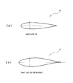
- FIG. 2 is a diagram illustrating an airfoil shape applicable to the vertical axis hydroelectric generator according to this embodiment.
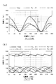
- FIG. 3 is a graph showing the state of the excitation force (N) with respect to the position angle (deg) of a plurality of blades included in the water turbine, and the diagram (a) in FIG. 3 shows the case where the number of blades is two.
- FIG. 3B shows a result when the number of blades is five.
- FIG. 4 is a graph showing changes in bending moment (N ⁇ m) as fatigue characteristics acting on the vertical rotation axis when the number of blades is increased by 1 between 2 and 9 blades. .
- FIG. 1 is an external perspective view showing the overall configuration of a vertical axis hydroelectric power generation unit according to this embodiment.
- FIG. 2 is a diagram illustrating an airfoil shape applicable to the vertical axis hydro
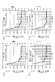
- FIG. 5 is a graph showing the result of verifying the influence of the installation cost when the number of blades is increased by 1 to 2 blades.
- FIG. 6 is a graph showing different changing tendencies indicated by the bending moment (N ⁇ m) as fatigue characteristics acting on the vertical rotation axis depending on whether the number of blades is even or odd.
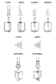
- FIG. 7 is a diagram illustrating a specific configuration example of an external shape that can be taken by the vertical axis hydroelectric generator according to the present embodiment.
- FIG. 8 is a diagram illustrating a specific configuration example of the external shape that can be taken by the vertical axis hydroelectric generator according to the present embodiment.
- FIG. 9 is a diagram illustrating a specific configuration example of an external shape that can be taken by the vertical axis hydroelectric generator according to the present embodiment.
- FIG. 10 is a diagram illustrating a specific configuration example of an external shape that can be taken by the vertical axis hydroelectric generator according to the present embodiment.
- FIG. 11 is a diagram illustrating a specific configuration example of an external shape that can be taken by the vertical axis hydroelectric generator according to the present embodiment.
- FIG. 12 is a diagram illustrating a specific configuration example of an external shape that can be taken by the vertical axis hydroelectric generator according to the present embodiment.
- FIG. 13 is a diagram showing a detailed structure of a single blade according to the present embodiment. In FIG. 13, (a) shows a side view of one blade, and (b) shows a single blade. A top view is shown.
- FIG. 14 is a diagram showing a fluctuation state of a load acting when one blade makes one rotation.
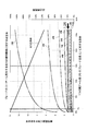
- FIG. 15 is a graph showing the safety factor against the fatigue limit of the stress generated at the corner of the blade and the output utilization factor.
- the horizontal axis shows the ratio of the corner radius part to the blade total length
- the left vertical axis shows the fatigue limit. Is the safety factor
- the right vertical axis shows the output utilization factor.
- 16 is an enlarged graph of the graph shown in FIG. 15, and shows a case where the safety factor with respect to the fatigue limit on the left vertical axis in FIG. 15 is in the range of 0-4.
- FIG. 1 is an external perspective view showing the entire configuration of the vertical axis hydroelectric power generation unit according to the present embodiment
- FIG. 2 is an airfoil applicable to the vertical axis hydroelectric power generation apparatus according to the present embodiment. It is a figure which illustrates a shape.
- the vertical axis hydroelectric generator 10 is an apparatus that generates electric power by rotating a water turbine 11 constituted by blades 13 by a water flow and transmitting the rotational movement to a generator 50.
- a vertical axis hydroelectric generator 10 according to this embodiment includes a water turbine 11 that is rotated by a water flow, a vertical rotation shaft 20 in which the water turbine 11 is installed, and a vertical axis.
- the bearing support unit 30 includes a bearing that rotatably supports the rotating shaft 20, and a generator 50 that generates electric power by the rotational driving force of the vertical rotating shaft 20.
- shaft type hydroelectric generator 10 which concerns on this embodiment is installed in a water channel, for example.
- a support body 60 for supporting the water wheel 11 and the vertical rotation axis 20 which are rotating members and for fixing and installing the vertical axis type hydroelectric generator 10 is provided. It is installed so as to surround the bearing support portion 30, and a bridge portion 61 is connected to the support body 60 so as to span the irrigation channel.
- the vertical shaft hydroelectric power generation unit 100 according to this embodiment is installed by fixing the support body 60 and the bridge portion 61 to the base portion 62 provided on both sides of the water channel, for example. Yes.
- a water turbine 11 illustrated in FIG. 1 is configured such that a plurality of blades 13 constituting the water turbine are arranged at substantially equal angular intervals around the vertical rotation shaft 20 in the circumferential direction.
- the case where the blade 13 of this is installed is illustrated.
- Each of the three blades 13 is configured to have an outer shape formed of a substantially U-shape, and is disposed so that the substantially U-shaped opening portion faces the vertical rotation shaft 20.
- a substantially U-shaped vertical bar portion is formed to extend in the vertical direction, and the cross-sectional shape thereof is formed as a straight wing having an airfoil shape.
- the substantially U-shaped vertical bar portion that is formed as a straight wing and extends in the vertical direction functions as a blade portion of the water turbine 11.
- the three blades 13 are arranged in water and receive a force from the water flow (water thrust force), thereby forming a straight line having an airfoil shape.
- the blade 12 as a wing receives a water flow to generate lift, and rotates about the center of the water turbine 11 (vertical rotating shaft 20).
- airfoil shape of the cross-sectional shape which the blade 13 has as shown in FIG. 2
- all types of airfoil shapes can be adopted.
- NACA National Aeronautics Advisory Committee: For Aeronautics
- NASA National Aeronautics and Aerospaceics Administration
- the airfoil “NACA0018” may be adopted, or the airfoil “TWT12013-05-BA642” developed at Tokai University as shown in the partial diagram (b) in FIG. 2 may be adopted. .
- the vertical rotating shaft 20 is a member that is rotationally moved by receiving the rotational force generated by the action of the blade 13 with the three blades 13 installed on the lower end side thereof.
- the vertical rotating shaft 20 and the three blades 13 are securely fastened and fixed by known fastening means such as bolts and nuts.
- the vertical rotation shaft 20 is rotatably supported by a bearing provided in the bearing support portion 30.
- the rotation of the vertical rotating shaft 20 is supported by the bearing support portion 30 and transmitted to the generator 50, and the generator 50 generates electric power.
- the generator 50 according to the present embodiment is installed such that an input shaft (not shown) included in the generator 50 is coaxial with the vertical rotation shaft 20.
- an input shaft (not shown) provided in the generator 50 is arranged coaxially with the vertical rotating shaft 20. It doesn't have to be. Then, the generated electric power is transmitted to a power consuming place, a power storage unit, and the like by a power transmission unit (not shown).
- FIG. 3 is a graph showing the state of the excitation force (N) with respect to the position angle (deg) of the plurality of blades 13 included in the water turbine 11, and the diagram (a) in FIG. Shows the result when there are two blades, and FIG. 3B shows the result when the number of blades is five.
- the load amplitude per rotation of the water turbine is about 350 N, whereas in the case of the water turbine 11 having five blades, the water turbine 1.
- the load amplitude per rotation was about 50 N, and there was an opening of about 7 times between the two load amplitudes. Therefore, in the vertical axis hydroelectric generator 10, it is possible to find a hypothesis that the greater the number of blades 13, the smaller the excitation force (fatigue load) generated on the blades 13 of the water turbine 11. it can.
- FIG. 4 shows a change in bending moment (N ⁇ m) as a fatigue characteristic acting on the vertical rotating shaft 20 when the number of blades is increased by 1 between 2 and 9.
- FIG. 4 shows a change in bending moment (N ⁇ m) as a fatigue characteristic acting on the vertical rotating shaft 20 when the number of blades is increased by 1 between 2 and 9.
- the bending moment (N ⁇ m) when the number of blades is 6 or more is also greatly suppressed compared to when the number of blades is 2, and the number of blades is at least 3 It was confirmed that the bending moment (N ⁇ m) as fatigue characteristics acting on the vertical rotating shaft 20 can be significantly reduced by using more than one.
- FIG. 5 is a graph showing the result of verifying the influence of the installation cost when the number of blades is increased by 1 between 2 and 9.
- the graph shown in FIG. 5 also includes a graph showing a change in bending moment (N ⁇ m) as fatigue characteristics acting on the vertical rotating shaft 20 shown in FIG. It was decided to.
- the inventors found that it is possible to reduce the bending moment (N ⁇ m) as fatigue characteristics acting on the vertical rotating shaft 20 by reducing the number of blades to at least 3 or more.
- the idea was that the turbine mechanical mass of the entire vertical axis hydroelectric generator 10 can be reduced by reducing the moment (N ⁇ m).
- the “turbine mechanical mass” means the mass of the vertical axis type hydroelectric power generator alone excluding the blade portions (11, 13) and the bridge portions (60, 61) among the members shown in FIG. Show. This can be represented by a single mass because the diameter of the shaft, which is the vertical rotating shaft 20, can be reduced as the number of blades increases.
- the mass of the vertical axis hydroelectric generator alone was designed and examined.
- the mass ratio of the water wheel mechanical is shown as an absolute value, but as is apparent from this figure, when the number of blades is three or more, the number of blades As compared with the case of two, it became clear that the turbine mechanical mass can be greatly reduced.
- This mass ratio tendency of the mechanical mass of the turbine is very consistent with the numerical tendency of the bending moment (N ⁇ m) as a fatigue characteristic, and the results are as expected by the inventors.
- the inventors also examined the “bridge mass” defined by the bridge portion (60, 61). Then, after considering the bending moment (N ⁇ m) as the fatigue characteristics, the “bridge mass” defined by the bridge portion (60, 61) was designed and examined. As a result, a partial diagram (b) in FIG. As shown, bridge mass values for each number of blades were obtained. Here, in the fractional diagram (b) in FIG. 5, the bridge mass is shown as a mass ratio that is an absolute value. As is apparent from this figure, the “bridge mass” is also the case of “turbine mechanical mass”.
- the bridge mass can be greatly reduced as compared with the case where the number of blades is two.
- the mass ratio tendency of the bridge mass is also very consistent with the numerical tendency of the bending moment (N ⁇ m) as fatigue characteristics, and the results are as expected by the inventors.
- the vertical axis hydroelectric power generation unit 100 can be introduced into a familiar water channel that could not be introduced.
- the number of blades was 2, 6-9, the cost increased significantly, and it became clear that the installation cost did not match the economic rationality.
- the number of blades is 10 or more, it is clear that the blade manufacturing cost will increase as in the case of 6 to 9 blades. do not do.
- the vertical axis hydroelectric generator 10 is optimally configured by configuring the number of blades 13 constituting the water turbine 11 with 3 to 5 blades. It was revealed that a vertical axis hydroelectric power generation unit 100 can be obtained. That is, by introducing the vertical shaft type hydroelectric generator 10 having 3 to 5 blades 13 constituting the water turbine 11, the vibration generated due to the influence of the water flow while securing sufficient output characteristics. An unprecedented vertical-axis hydroelectric power generation unit 100 that can suppress the force (fatigue load) to a low level and can minimize the mass of the structure and the installation cost of the entire apparatus can be provided. It becomes.
- the verification contents using the single flow management theory by the inventors described with reference to FIGS. 3 to 5 are based on a completely new idea that has never been seen in the vertical axis hydroelectric generator field. It should be noted that this is a research result that the inventors have made and obtained newly.
- FIG. 6 is a graph showing different change tendencies indicated by the bending moment (N ⁇ m) as the fatigue characteristics acting on the vertical rotation axis depending on whether the number of blades is even or odd.
- the function of the blade is decreased to cancel the effect of increasing the number of blades, and the bending moment (N ⁇ m) is greater when the number of blades is even than when the number of blades is odd. I think that will have a tendency to increase.
- the imaginary lines indicated by the symbols x and y in FIG. 6 can be drawn using a known method such as the minimum two-row method as a means for calculating an approximate curve of a point sequence.
- the number of blades 13 constituting the water turbine 11 is an odd number, that is, three or five blades.
- the optimum vertical axis hydroelectric power generation unit 100 can be obtained.
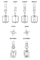
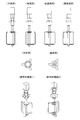
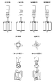
- FIG. 7 to FIG. 12 are shown as configuration examples specifically illustrating the above-described vertical axis hydroelectric generator 10 according to the present embodiment.
- FIG. 7 to FIG. 12 are diagrams showing specific configuration examples of the external shape that the vertical axis hydroelectric generator 10 according to the present embodiment can take.
- 7 and 10 show the vertical axis hydroelectric generator 10 when the number of blades 13 constituting the water turbine 11 is three
- FIGS. 8 and 11 show the blades 13 constituting the water turbine 11.
- FIG. 9 and FIG. 12 show the vertical axis hydraulic power generation apparatus 10 in the case where the number of blades 13 constituting the water turbine 11 is five. Show.
- the solidity of the water turbine 11 composed of a plurality of blades 13 is configured to be 0.1 to 0.29.
- the solidity is an index expressed as a ratio of the total blade area to the rotation area of the blade, and is expressed by the following formula (1).
- the vertical axis hydroelectric generator 10 and the vertical axis hydroelectric generator unit 100 according to the present embodiment can be obtained by configuring the solidity to be 0.1 to 0.29. ing. That is, when the solidity is 0.1 to 0.29 and the number of blades 13 is 3 to 5, the excitation force generated by the influence of the water flow while ensuring sufficient output characteristics. (Fatigue load) can be suppressed to a small size, and the mass of the structure and the installation cost of the entire apparatus can be minimized. 100 can be provided.
- the invention described with reference to FIGS. 3 to 6 focuses on the influence of the excitation force (fatigue load) generated on the blade 13 of the water turbine 11 by the thrust force of the water flow, and also “turbine mechanical mass” and “ This was derived by considering the cost effect of the entire apparatus, which is the sum of the cost effect based on the “bridge mass” and the cost effect based on the increase in the number of blades.
- the inventors have obtained new knowledge about suitable configuration conditions of the vertical axis hydroelectric generator 10. Based on this knowledge, the inventors have succeeded in finding a further optimized configuration condition of the vertical axis hydroelectric generator by advancing research based on a new viewpoint. Accordingly, next, another new configuration condition of the vertical axis hydroelectric generator 10 according to the present embodiment will be described with reference to FIGS.
- FIG. 13 is a diagram showing a detailed structure of a single blade according to the present embodiment.
- (a) is a side view of one blade
- (b) is one sheet.
- the top view of the blade is shown.
- FIG. 14 is a diagram showing a fluctuation state of a load acting when one blade makes one rotation.
- FIG. 15 is a graph showing the safety factor against the fatigue limit of stress generated at the corner portion (corner radius portion) of the blade and the output utilization factor, and the ratio of the corner radius portion to the blade total length is shown on the horizontal axis.
- the left vertical axis shows the safety factor against the fatigue limit
- the right vertical axis shows the output utilization rate.
- FIG. 16 is an enlarged graph of the graph shown in FIG.
- the ratio of the corner radius portion 13b shown on the horizontal axis to the blade total length L is either one of the upper and lower corner radius portions 13b of one blade. This is the ratio calculated based on the radius R of the radius of curvature of the portion 13b.
- one blade 13 includes a blade linear portion 13 a formed extending in the vertical direction and a vertical rotation shaft 20.
- the force of the water flow acts on the blade straight portion 13a and the pair of upper and lower corner radius portions 13b, so that the water turbine 11 rotates.
- the portion where the stress is maximum in one blade 13 is the corner radius portion 13b. That is, if the corner radius portion 13b is small or absent, the strength of the blade 13 is reduced and the water turbine 11 is destroyed in the worst case.
- the corner radius portion 13b is large, the blade generating lift. The length of the straight line portion 13a is reduced and power generation efficiency is reduced. Therefore, if an optimized blade shape can be proposed from the viewpoint of the strength of the blade 13 and the power generation efficiency, a more preferable vertical axis hydroelectric generator 10 can be obtained.
- the inventors conducted research to obtain an optimum blade shape.
- the number of blades 13 constituting the water turbine 11 is increased within a range where the solidity of the water turbine 11 is 0.1 to 0.29, the chord length and blade thickness per blade are reduced. The strength of the will decrease.
- FIG. 14 when the water turbine 11 is rotating, a load that fluctuates in a complicated manner during one rotation is applied to one blade 13 constituting the water turbine 11.
- the radial load Fn varies greatly during one rotation of the blade 13 as compared to the tangential load Ft.
- the stress concentration factor varies depending on the radius of curvature R of the corner rounded portion 13b.
- the inventors calculated the amplitude of stress generated in the blade 13 when the size of the corner radius portion 13b is changed in each blade number (2 to 10) by numerical analysis.
- the safety factor for fatigue strength was calculated.
- the material constituting the blade 13 the strength, excellent ductile iron manufacturability, alloys, assuming a composite resin or the like, the calculated fatigue strength at repetition count 10 9 times as 75 ⁇ 180 MPa It was.
- the blade straight portion 13a which is an effective straight portion of the blade 13, is reduced, the performance as the blade is lowered, and the power generation efficiency is lowered.
- FIG. 15 and FIG. 16 summarize these calculation results.
- the dimension of the radius of curvature R of each of the pair of upper and lower corner round portions 13b formed on the blade 13 is the same value.
- the radius of curvature of each of the pair of upper and lower corner round portions 13b formed on the blade 13 is “R”, and the ratio of the corner round portion 13b shown on the horizontal axis to the blade total length L in FIGS. Is a ratio calculated based on the radius R of the curvature radius of one of the pair of upper and lower corner round portions 13b of one blade.
- the lower limit value of the radius of curvature R of the corner rounded portion 13b is verified.
- the safety factor decreases drastically due to stress concentration. Is clear. Therefore, it can be determined that the ratio of one corner rounded portion 13b to the entire length of the blade needs to be 1% or more. Therefore, from the viewpoint of ensuring the minimum necessary safety factor, assuming that the radius of curvature of one corner rounded portion 13b is R and the length of the entire blade 13 including a pair of upper and lower corner rounded portions 13b is L, It can be said that it is necessary to satisfy the inequality (2). 0.01L ⁇ R (2)
- the vertical axis hydroelectric generator 10 is a lift-type water turbine 11, which has been conventionally used for small hydroelectric generators. A higher power generation efficiency is required than a water turbine of a type that generates electricity by using the drag force of the water flow such as the “Savonius type”. Therefore, regarding the output utilization rate of the vertical axis hydroelectric generator 10 according to the present embodiment, in consideration of the fact that the water turbine 11 should ensure a certain facility capacity, a performance with an output utilization rate of 60% or more is secured at a minimum. There is a need to.
- the output utilization rate of the vertical axis hydroelectric generator 10 that should be ensured as a minimum is assumed to be 60% or more. However, in reality, a higher output utilization rate is obtained. It is necessary to consider what is required. Therefore, the inventors set the output utilization rate of 70% as a target value for ensuring performance in consideration of economic efficiency and customer's required specifications. Then, when the proportion of one corner rounded portion 13b with respect to the total length of the blade when the output utilization rate is 70% is read from the graph of FIG. 16, it can be determined that it is 15%.
- the inequality (4) can be adopted as a condition range that can be taken by the present invention.
- a vertical axis type employing the condition of the inequality (6). It can be said that it is more preferable to configure the hydroelectric generator 10.
- the safety factor against the fatigue limit of the material must be secured at least a safety factor of 1.25 or more from the provisions of IEC 61400-2, which is a safety standard for wind power generation that has the same design requirements as a water turbine. Can do.
- a line indicating this safety factor 1.25 is shown in FIGS. 15 and 16. Then, it can be determined that the number of blades satisfying the inequalities (4) and (6) while satisfying the safety factor of 1.25 or more is 6 or less. However, when the number of blades is 6, it is also clear from FIG.
- the number of blades is preferably 5 or less. This conclusion focuses on the influence of the invention described with reference to FIGS. 3 to 6, that is, the influence of the excitation force (fatigue load) generated on the blade 13 of the water turbine 11 by the thrust force of the water flow. It overlaps with the number of blades (3 to 5) derived by considering the cost effect of the entire device, including the cost effect based on "mechanical mass” and “bridge mass” and the cost effect based on the increase in the number of blades. Therefore, the reliability of this verification experiment was confirmed again.
- the vertical axis hydroelectric generator is a generator that generates electric power by receiving rotational driving force from a water stream, and a vertical unit that is rotatably connected to the generator and that is vertically suspended.
- a vertical shaft type hydroelectric generator comprising: a rotary shaft; and a plurality of blades arranged around the vertical rotary shaft at substantially equal angular intervals along the circumferential direction. It is formed as a straight wing having an airfoil shape and a cross-sectional shape, and when the plurality of blades are viewed from the bottom side, it is configured by the number of blades of 5 or less. To do.
- the plurality of blades are configured with 3 to 5 blades when viewed from the bottom side.
- each of the plurality of blades includes a corner radius portion having a curved shape at one end extending in the vertical direction, and the curvature radius of the corner radius portion is set.
- R when the length of the entire blade including the corner rounded portion is L, 0.01L ⁇ R ⁇ 0.20L It can be configured so that the following inequality holds.
- the inequality is 0.01L ⁇ R ⁇ 0.15L It can be constituted so that.
- the blade includes two corner round portions each having a curved shape at each of upper and lower end portions extending in the vertical direction. They can be formed with the same dimensions.
- the vertical axis hydroelectric generator according to the present invention can be configured such that the solidity of the plurality of blades is 0.1 to 0.29.
- the plurality of blades 13 installed around the vertical rotation shaft 20 are configured as straight blades each extending over the entire length of the water turbine 11 in the vertical direction.
- the plurality of blades according to the present invention is formed as a straight wing that is formed extending in the vertical direction and the cross-sectional shape is an airfoil shape, and when the plurality of blades are viewed from the bottom side, What is necessary is just to be comprised by the number of 5 or less blades.
- the turbine may be of a type in which the length of the blade is about half the vertical length of the turbine 11 and two upper and lower blades are provided.
- the blades need to be configured with five or less blades.
- the dimension of the radius of curvature R of each of the pair of upper and lower corner radius portions 13b formed on the blade 13 is described as being the same value in the upper and lower sides.
- the scope of the present invention is not limited to the scope of the present embodiment described above. That is, in the blade of the present invention, the size of the radius of curvature R of each corner rounded portion can be configured to be different between the upper and lower sides of the blade according to the installation environment of the vertical axis hydroelectric generator.
- the radius of curvature R of the upper corner radius portion is set to improve the strength on the upper side of the blade It is possible to employ a configuration in which the size of the radius of curvature R of the corner corner portion on the lower side of the blade is made smaller than that on the upper side.
- the installation environment of such a vertical axis hydroelectric generator may vary depending on the installation environment such as the material of the channel (for example, whether it is concrete or soil) and the surface condition in the channel. What is necessary is just to determine the dimension conditions of a corner
Landscapes
- Engineering & Computer Science (AREA)
- Chemical & Material Sciences (AREA)
- Combustion & Propulsion (AREA)
- Mechanical Engineering (AREA)
- General Engineering & Computer Science (AREA)
- Hydraulic Turbines (AREA)
Abstract
垂直軸型水力発電装置(100)は、水流からの回転駆動力を受けて電力を発生する発電機(50)と、発電機(50)に回転自在に連結されるとともに、鉛直方向に垂下設置される垂直回転軸(20)と、垂直回転軸(20)の周囲を円周方向に沿って略等角度間隔で配設された複数のブレード(13)とを備える。複数のブレード(13)は、鉛直方向に延びて形成されるとともに横断面形状が翼型形状からなる直線翼として形成され、かつ、当該複数のブレード(13)を底面側から見たときに、5枚以下のブレード数で構成される。かかる構成を備えることで、十分な出力特性を確保しながらも、水流の影響で発生する加振力(疲労荷重)を小さく抑えることができ、しかも、構造体の質量と装置全体の設置コストを最小限に抑えることのできる、従来にはない垂直軸型水力発電装置を提供することが可能となる。
Description
本発明は、垂直軸型水力発電装置および垂直軸型水力発電ユニットに関するものである。
従来から、水車が備えるブレードを水流によって回転運動させ、この回転運動を発電機に伝達することで電力を発生させる水力発電装置が知られている。従来の小型の水力発電装置には、水路を堰き止めて発電する「落差式」や、水流の抗力で発電する「サボニウス型」の水車が多く用いられてきた(例えば、下記特許文献1参照)。しかし、これらの水車を既存の水路に設置しようとする場合には、水路から水が溢れ出ないようにするための大掛かりな水路改造工事等が必要となるため、水力発電装置の設置場所には多くの制約が存在していた。また、水車の特性上、水路を流れるゴミが水車に堆積してしまうため、除塵装置と多額のメンテナンス費用も必要となる。つまり、従来の水力発電装置には、多大な初期コストと維持コストが必要となるなど、経済合理性の観点からその普及を阻害する要因が存在していた。
上述した従来の水力発電装置に存在する課題を解決する手法として、近年、揚力特性を利用した垂直軸型水力発電装置の実現が検討されている。この垂直軸型水力発電装置は、水流からの回転駆動力を受けて電力を発生する発電機と、発電機に回転自在に連結されるとともに、鉛直方向に垂下設置される垂直回転軸と、この垂直回転軸の周囲を円周方向に沿って略等角度間隔で配設された複数のブレードと、を備える装置であって、複数のブレードが水流に対して垂直方向に配置された形式を有することから、従来技術で必要であった除塵装置や多額のメンテナンス費用が不要となるメリットを備えるものである。
しかしながら、垂直軸型水力発電装置が想定する垂直方向に配置されるブレードは、風力発電には多く用いられているが、水力発電装置への普及は進んでいないのが現状である。なぜなら、風車に利用される風(空気)とは異なり、水車に利用される水流(水)は、空気の約800倍の密度を持つため、ブレードに定常的に加わる水流からの荷重が非常に大きくなるという課題が存在している。すなわち、発電効率を向上させるためにブレードの出力を大きくしようとすると、たとえ一定流速の流水から力を受ける場合であっても、水車全体には非常に大きな荷重が加わり、振動に基づく疲労荷重の影響も大なるものがある。特に、垂直軸型水力発電装置の場合、水路を流れる流水中に配置されるブレードは、片持ち梁の構造となるため、水流からの大荷重と加振による疲労荷重に耐え得るためには、強固な構造体が必要となる。つまり、既存の垂直軸型水力発電装置には、従来の他形式の水力発電装置には存在しない形式上のメリットがあるものの、垂直軸型水力発電ユニットとして、仕様によっては設置コストを増大化させる虞があった。
本発明は、上述した従来技術に存在する課題の存在に鑑みて成されたものであり、その目的は、十分な出力特性を確保しながらも、水流の影響で発生する加振力(疲労荷重)を小さく抑えることができ、しかも、構造体の質量と装置全体の設置コストを最小限に抑えることのできる、従来にはない垂直軸型水力発電装置を提供することにある。
本発明に係る垂直軸型水力発電装置は、水流からの回転駆動力を受けて電力を発生する発電機と、前記発電機に回転自在に連結されるとともに、鉛直方向に垂下設置される垂直回転軸と、前記垂直回転軸の周囲を円周方向に沿って略等角度間隔で配設された複数のブレードと、を備える垂直軸型水力発電装置であって、前記複数のブレードは、鉛直方向に延びて形成されるとともに横断面形状が翼型形状からなる直線翼として形成され、かつ、当該複数のブレードを底面側から見たときに、5枚以下のブレード数で構成されることを特徴とするものである。
本発明によれば、十分な出力特性を確保しながらも、水流の影響で発生する加振力(疲労荷重)を小さく抑えることができ、しかも、構造体の質量と装置全体の設置コストを最小限に抑えることのできる、従来にはない垂直軸型水力発電装置を提供することができる。
以下、本発明を実施するための好適な実施形態について、図面を用いて説明する。なお、以下の実施形態は、各請求項に係る発明を限定するものではなく、また、実施形態の中で説明されている特徴の組み合わせの全てが発明の解決手段に必須であるとは限らない。
まず、本実施形態に係る垂直軸型水力発電ユニット100の全体構成例について説明を行う。ここで、図1は、本実施形態に係る垂直軸型水力発電ユニットの全体構成を示す外観斜視図であり、図2は、本実施形態に係る垂直軸型水力発電装置に適用可能な翼型形状を例示する図である。
本実施形態に係る垂直軸型水力発電装置10は、ブレード13によって構成される水車11を水流によって回転運動させ、当該回転運動を発電機50に伝達することで電力を発生させる装置である。具体的な構成としては、図1にて示すように、本実施形態に係る垂直軸型水力発電装置10は、水流により回転する水車11と、水車11が設置される垂直回転軸20と、垂直回転軸20を回転可能に支持する軸受を備える軸受サポート部30と、垂直回転軸20の回転駆動力により電力を発生する発電機50と、を有して構成される。そして、本実施形態に係る垂直軸型水力発電装置10は、例えば用水路に設置される。
また、垂直軸型水力発電ユニット100としては、回転部材である水車11や垂直回転軸20を支持し、垂直軸型水力発電装置10の固定設置を行うための支持体60が垂直回転軸20や軸受サポート部30を取り囲むように設置されており、この支持体60には、用水路等に架け渡されるブリッジ部61が接続されている。支持体60とブリッジ部61とが、例えば用水路の両岸に設けられた基礎部62に対して固定設置されることで、本実施形態に係る垂直軸型水力発電ユニット100の設置が行われている。
図1で例示する水車11は、当該水車を構成する複数のブレード13が垂直回転軸20の周囲を円周方向に沿って略等角度間隔で配設されたものであり、図1では3枚のブレード13が設置された場合が例示されている。これら3枚のブレード13は、それぞれが略コ字形からなる外観形状を有して構成されており、略コ字形の開放部が垂直回転軸20に対して向くように設置されている。また、略コ字形の縦棒部が鉛直方向に延びて形成されるとともに、その横断面形状が翼型形状からなる直線翼として形成されている。このように直線翼として形成される鉛直方向に延びた略コ字形の縦棒部が、水車11の羽根部として機能する。すなわち、本実施形態に係る水車11は、図1に示すように、3枚のブレード13が水中に配置されて水流からの力(水のスラスト力)を受けることで、翼型形状からなる直線翼としてのブレード12が水流を受けて揚力を発生し、水車11の中心(垂直回転軸20)を中心軸として回転するようになっている。
なお、ブレード13が有する横断面形状の翼型形状については、図2で例示するように、あらゆる形式の翼型形状を採用することができる。例えば、図2中の分図(a)で示すような、NASA(アメリカ航空宇宙局:National Aeronautics and Space Administration)の前身であるNACA(アメリカ航空諮問委員会:National Advisory Committee for Aeronautics)が定義した「NACA0018」なる翼型を採用しても良いし、図2中の分図(b)で示すような、東海大学で開発された「TWT12013-05-BA642」なる翼型を採用しても良い。
垂直回転軸20は、上述したように、その下端側に3枚のブレード13が設置され、ブレード13の作用によって発生する回転力を受けることで、回転運動する部材である。垂直回転軸20と3枚のブレード13とは、例えばボルトおよびナット等のような公知の締結手段によって、確実に締結固定がなされている。そして、垂直回転軸20は、軸受サポート部30に備えられる軸受により回転可能に支持される。
垂直回転軸20の回転は、軸受サポート部30によって支持され、発電機50に伝達され、発電機50が電力を発生させることとなる。なお、本実施形態に係る発電機50は、発電機50の備える不図示の入力軸が、垂直回転軸20と同軸となるように設置されている。ただし、発電機50と垂直回転軸20とが遊星歯車や減速器を使用して接続される形態の場合には、発電機50の備える不図示の入力軸は、垂直回転軸20と同軸で配置されていなくとも良い。そして、発電された電力は、不図示の送電手段によって、電力消費地や蓄電手段等へと送電される。
以上、本実施形態に係る垂直軸型水力発電ユニット100の全体構成例についての説明を行った。次に、上述した垂直軸型水力発電ユニット100に基づき、発明者らが行った実験結果について説明する。以下で説明する実験結果は、十分な出力特性を確保しながらも、水流の影響で発生する加振力(疲労荷重)を小さく抑えることができ、しかも、構造体の質量と装置全体の設置コストを最小限に抑えることのできる、従来にはない垂直軸型水力発電装置10および垂直軸型水力発電ユニット100を得るために、発明者らが初めて着想して検討し、得られた成果である。
まず、発明者らは、垂直軸型水力発電装置10および垂直軸型水力発電ユニット100で課題となる影響のうち、水流のスラスト力によって水車11のブレード13に発生する加振力(疲労荷重)の影響について着目した。そして、発明者らは、単一流管理論より、直線翼からなるブレード13を有する水車11のロータ特性(疲労荷重特性)を解析し、図3で示す結果を得た。ここで、図3は、水車11が有する複数のブレード13の位置角(deg)に対する加振力(N)の様子を示したグラフ図であり、図3中の分図(a)はブレード枚数が2枚の場合の結果を示し、図3中の分図(b)はブレード枚数が5枚の場合の結果を示している。
図3中の分図(a)で示す通り、ブレード枚数が2枚の場合では、各ブレード13に加わる加振力(N)の変動が非常に大きく、また、これら2枚のブレード13に加わる加振力(N)の合計値についても、符号αで示す矢印幅の通り、非常に大きな振幅変動を有するものであった。
一方、ブレード枚数が5枚の場合では、図3中の分図(b)で示す通り、各ブレード13に加わる加振力(N)の変動は比較的小さく、また、これら5枚のブレード13に加わる加振力(N)の合計値についても、加振力(N)を互いに打ち消し合うことで、符号βで示す矢印幅の通り、非常に小さな振幅変動を有するものとなることが確認できた。
以上の結果から分かることとして、ブレード枚数が2枚の水車11の場合、水車1回転あたりの荷重振幅は、約350N強であるのに対し、ブレード枚数が5枚の水車11の場合、水車1回転あたりの荷重振幅は、約50N弱であり、両者の荷重振幅には約7倍もの開きが存在していた。したがって、垂直軸型水力発電装置10においては、ブレード13の枚数が多いほど、水車11のブレード13に発生する加振力(疲労荷重)が小さくなるのではないか、との仮説を見出すことができる。
そこで次に、発明者らは、ブレード枚数の違いが、垂直回転軸20に作用する疲労特性としての曲げモーメント(N・m)にどのような違いをもたらすのかについての検証を行った。その結果を、図4に示す。ここで、図4は、ブレード枚数が2枚~9枚の間で1枚ずつ増加させたときに、垂直回転軸20に作用する疲労特性としての曲げモーメント(N・m)の変化を示したグラフ図である。
図4で示すように、ブレード枚数が2枚から3枚、4枚、5枚まで増加するにつれ、垂直回転軸20に作用する疲労特性としての曲げモーメント(N・m)は暫時減少して行くことが確認できた。ただし、ブレード枚数が6枚のときは、5枚の場合に比べて曲げモーメント(N・m)が僅かに増加することが確認できた。さらに、ブレード枚数が6枚以上となると、垂直回転軸20に作用する疲労特性としての曲げモーメント(N・m)は、あまり変化せず、ブレード枚数の増加による曲げモーメント(N・m)への影響が減少して行くことが確認できた。ただし、ブレード枚数が6枚以上の場合の曲げモーメント(N・m)についても、ブレード枚数が2枚のときと比較すると曲げモーメント(N・m)が大きく抑えられており、ブレード枚数を少なくとも3枚以上とすることで、垂直回転軸20に作用する疲労特性としての曲げモーメント(N・m)を大幅に減少させることが可能であることを確認できた。
続いて、発明者らは、垂直軸型水力発電装置10および垂直軸型水力発電ユニット100の普及を阻害するもう一つの要因である設置コストの影響について、検証することとした。その結果を、図5に示す。ここで、図5は、ブレード枚数が2枚~9枚の間で1枚ずつ増加させたときの設置コストの影響について検証した結果を示すグラフ図である。なお、図5において示すグラフ図には、説明の便宜のために、図4で示した垂直回転軸20に作用する疲労特性としての曲げモーメント(N・m)の変化を示したグラフについても併記することとした。
まず、発明者らは、ブレード枚数を少なくとも3枚以上とすることで、垂直回転軸20に作用する疲労特性としての曲げモーメント(N・m)を減少させることが可能となるとの知見から、曲げモーメント(N・m)の減少によって、垂直軸型水力発電装置10全体の水車メカ質量を減少させることができるのでは、との着想を得た。ここで、「水車メカ質量」とは、図1で示した部材のうち、ブレード部分(11,13)とブリッジ部分(60,61)とを除いた垂直軸型水力発電装置単体での質量を示している。これは、ブレード枚数の増加に伴い、垂直回転軸20であるシャフトの直径を小さくできるため、単体の質量で示すことができる。そして、疲労特性としての曲げモーメント(N・m)を考慮した上で、垂直軸型水力発電装置単体での質量を設計検討した結果、図5中の分図(a)で示すように、ブレード枚数毎の水車メカ質量の値を得た。ここで、図5中の分図(a)では、水車メカ質量が絶対値である質量比で示してあるが、この図から明らかな通り、ブレード枚数が3枚以上の場合には、ブレード枚数が2枚のときと比較して、水車メカ質量を大きく減少させることが可能であることが明らかとなった。この水車メカ質量の質量比傾向は、疲労特性としての曲げモーメント(N・m)の数値傾向と非常に合致しており、発明者らの予想通りの結果となった。
上記の結果を得て、発明者らは、ブリッジ部分(60,61)で定義される「ブリッジ質量」についての検討も行った。そして、疲労特性としての曲げモーメント(N・m)を考慮した上で、ブリッジ部分(60,61)で定義される「ブリッジ質量」を設計検討した結果、図5中の分図(b)で示すように、ブレード枚数毎のブリッジ質量の値を得た。ここで、図5中の分図(b)では、ブリッジ質量が絶対値である質量比で示してあるが、この図から明らかな通り、「ブリッジ質量」についても「水車メカ質量」の場合と同様に、ブレード枚数が3枚以上の場合には、ブレード枚数が2枚のときと比較して、ブリッジ質量を大きく減少させることが可能であることが明らかとなった。このブリッジ質量の質量比傾向についても、疲労特性としての曲げモーメント(N・m)の数値傾向と非常に合致しており、発明者らの予想通りの結果となった。
以上説明したように、ブレード枚数が3枚以上の場合には、ブレード枚数が2枚のときと比較して、「水車メカ質量」と「ブリッジ質量」を大きく減少させることが可能であることが明らかとなった。これら「水車メカ質量」と「ブリッジ質量」を大きく減少させることで、当然に設置コストの削減効果が得られるはずである。ただし、ブレード枚数を増加させることは、ブレード作成費用を増加させることにもつながるものである。そこで、発明者らは、ブレード枚数が2枚~9枚の間で1枚ずつ増加させたときのブレード製造コストの増加影響について検証した。その結果を示すグラフ図が、図5中の分図(c)である。
ここで、水車11を構成するブレード13については、CFRP(炭素繊維強化プラスチック:carbon-fiber-reinforced plastic)等の非常に高価な素材を用いて製造されるため、ブレード枚数の増加はそのまま製造コストの増加に比例的に影響を及ぼすこととなる。その結果が、図5中の分図(c)に示されており、ブレード枚数の増加は、ブレードを合算した水車全体のコストを比例的に増加させることが明らかである。
そして、上述した「水車メカ質量」と「ブリッジ質量」に基づくコスト影響と、ブレード枚数の増加に基づくコスト影響とを合算した装置全体のコスト影響を、図5中の分図(d)に示す。図5中の分図(d)からも明らかな通り、ブレード部分(11,13)と水車メカ部分(20,30,50)、およびブリッジ部分(60,61)の合計コストを確認した結果、ブレード枚数が3枚、4枚、5枚の場合についてはコストが抑制されており、この設置コストで垂直軸型水力発電ユニット100を導入できれば、経済合理性の観点からも採算が合い、これまで導入できなかった身近な水路に対して本実施形態に係る垂直軸型水力発電ユニット100を導入できることが明らかとなった。一方、ブレード枚数が2枚、6枚~9枚の場合についてはコストが大きく上昇してしまい、設置コストの面から経済合理性に合わないことが明らかとなった。なお、ブレード枚数が10枚以上の場合については、6枚~9枚の場合と同様に、ブレード製造コストが増加することが明らかなので、10枚以上についても設置コストの面から経済合理性に合致しない。
以上説明した発明者による検証から、本実施形態に係る垂直軸型水力発電装置10については、水車11を構成するブレード13の枚数を3枚~5枚のブレード数で構成することによって、最適な垂直軸型水力発電ユニット100が得られることが明らかとなった。すなわち、水車11を構成するブレード13の枚数が3枚~5枚である垂直軸型水力発電装置10を導入することで、十分な出力特性を確保しながらも、水流の影響で発生する加振力(疲労荷重)を小さく抑えることができ、しかも、構造体の質量と装置全体の設置コストを最小限に抑えることのできる、従来にはない垂直軸型水力発電ユニット100を提供することができることとなる。なお、図3~図5を用いて説明した発明者らによる単一流管理論を用いた検証内容については、少なくとも垂直軸型水力発電装置の分野ではこれまでに無い全く新しい着想に基づくものであり、発明者らが新規に行い、得ることのできた研究成果であることを付言しておく。
さて、上述した新規な研究成果を得た発明者らは、水車11を構成するブレード13の枚数を3枚~5枚とするという条件について、さらに最適化することができないかを検証・検討した。その際、図4で示したブレード枚数毎の垂直回転軸20に作用する疲労特性としての曲げモーメント(N・m)の変化を示したグラフ図を再度検証することとした。その結果、図6で示すように、このブレード枚数毎の曲げモーメント(N・m)の変化点については、ブレード枚数が偶数の場合と奇数の場合とで異なる傾向を示すことを確認することができた。ここで、図6は、ブレード枚数が偶数の場合と奇数の場合とで、垂直回転軸に作用する疲労特性としての曲げモーメント(N・m)が示す異なる変化傾向を示したグラフ図である。
すなわち、図6中の符号xで示すように、ブレード枚数が偶数の場合の曲げモーメント(N・m)値を仮想線xで結ぶと、図6中の符号yで示すように、ブレード枚数が奇数の場合の曲げモーメント(N・m)値を仮想線yで結んだ場合の方が、偶数の仮想線xの場合に比べて曲げモーメント(N・m)の値が小さくなる傾向があることが分かる。この事実についての明確な理論説明は未だ不十分ではあるが、発明者らが考えるに、ブレード枚数が偶数の場合、垂直回転軸20の周囲を対向して各ブレード13が配置されることになるので、水流に対してブレードが重畳する箇所が生じることとなる。その結果、ブレードの機能を減少させてブレード枚数の増加効果を相殺する作用が働くことで、ブレード枚数が奇数の場合に比べてブレード枚数が偶数の場合の方が、曲げモーメント(N・m)が増加してしまう傾向を有することになるのではないかと考えている。
なお、図6中の符号xおよびyで示す仮想線は、例えば、点列の近似曲線を計算する手段としての最小二条法などの周知の手法を用いて描くことができる。
以上説明した図6を用いた仮説に基づけば、本実施形態に係る垂直軸型水力発電装置10については、水車11を構成するブレード13の枚数を奇数枚、すなわち、3枚又は5枚のブレード数で構成することによって、最適な垂直軸型水力発電ユニット100が得られることとなる。
以上、本発明の好適な実施形態について説明した。なお、上述した本実施形態に係る垂直軸型水力発電装置10を具体的に例示する構成例として、図7~図12を示す。ここで、図7~図12は、本実施形態に係る垂直軸型水力発電装置10が取り得る外観形状の具体的な構成例を示す図である。なお、図7および図10は、水車11を構成するブレード13の枚数が3枚の場合の垂直軸型水力発電装置10を示しており、図8および図11は、水車11を構成するブレード13の枚数が4枚の場合の垂直軸型水力発電装置10を示しており、図9および図12は、水車11を構成するブレード13の枚数が5枚の場合の垂直軸型水力発電装置10を示している。
そして、図7~図12で示す垂直軸型水力発電装置10において、複数のブレード13によって構成される水車11のソリディティは、0.1~0.29となるように構成されている。ここで、ソリディティとは、翼の回転面積に対する全翼面積の比として示される指標であり、以下の数式(1)であらわされるものである。
ソリディティ(ρ)=n×C/(2πr) ・・・ (1)
ただし、n=翼枚数、C=翼弦長(m)、r=水車半径 とする。
ソリディティ(ρ)=n×C/(2πr) ・・・ (1)
ただし、n=翼枚数、C=翼弦長(m)、r=水車半径 とする。
上記の事実は、ソリディティが、0.1~0.29となるように構成することで、本実施形態に係る垂直軸型水力発電装置10および垂直軸型水力発電ユニット100を得られることも示している。すなわち、ソリディティが0.1~0.29であり、かつ、ブレード13の枚数を3枚~5枚とすることで、十分な出力特性を確保しながらも、水流の影響で発生する加振力(疲労荷重)を小さく抑えることができ、しかも、構造体の質量と装置全体の設置コストを最小限に抑えることのできる、従来にはない垂直軸型水力発電装置10および垂直軸型水力発電ユニット100を提供することができる。
以上、図3~図6を用いて説明した発明事項は、水流のスラスト力によって水車11のブレード13に発生する加振力(疲労荷重)の影響について着目するとともに、「水車メカ質量」と「ブリッジ質量」に基づくコスト影響と、ブレード枚数の増加に基づくコスト影響とを合算した装置全体のコスト影響を考慮することで導き出されたものであった。かかる発明事項によって、発明者らは、垂直軸型水力発電装置10の好適な構成条件についての新たな知見を得るに至った。この知見を踏まえ、発明者らは、新たな観点に基づく研究を進めることで、さらに最適化された垂直軸型水力発電装置の構成条件を見出すことに成功した。そこで、次に、図13~図16を用いることで、本実施形態に係る垂直軸型水力発電装置10の別の新たな構成条件についての説明を行う。
ここで、図13は、本実施形態に係るブレード単体の詳細な構造を示す図であり、図中の分図(a)は1枚のブレードの側面視を、分図(b)は1枚のブレードの上面視を示している。また、図14は、1枚のブレードが1回転する際に作用する荷重の変動状況を示した図である。さらに、図15は、ブレードのコーナー部(隅アール部)に発生する応力の疲労限度に対する安全率と、出力利用率を示したグラフ図であり、横軸に隅アール部のブレード全長に対する割合が、左縦軸に疲労限度に対する安全率が、右縦軸に出力利用率が示されている。またさらに、図16は、図15で示したグラフ図を拡大したグラフ図であって、図15における左縦軸の疲労限度に対する安全率が0~4の範囲である場合が示されている。なお、図15および図16において、横軸に示された隅アール部13bのブレード全長Lに対する割合については、1枚のブレードが有する上下一対の隅アール部13bのうち、いずれか一方の隅アール部13bの曲率半径の寸法Rに基づき算出された割合である。
さて、発明者らは、図3~図6を用いて説明した発明事項を満足するとともに、図7~図12で示すように、水車11のソリディティが0.1~0.29となるように構成された垂直軸型水力発電装置10を実際に水流中で運用すると、ブレード13に対する水流からの力が非常に大きく、ブレード強度を考慮したブレード設計が必要であることを再認識した。特に、本実施形態に係る垂直軸型水力発電装置10については、図13に示すように、1枚のブレード13は、鉛直方向に延びて形成されたブレード直線部13aと、垂直回転軸20から水平方向に延びて形成される上下一対のブレードアーム部13cと、1つのブレード直線部13aと2つのブレードアーム部13cとの接続部に形成された上下一対の隅アール部13bとによって構成されている。つまり、水流からの力が、ブレード直線部13aと上下一対の隅アール部13bとに作用することで、水車11の回転運動が行われることになる。そしてこの際、1枚のブレード13において応力が最大となる箇所が、隅アール部13bとなることが知られている。すなわち、隅アール部13bが小さい、もしくは無いと、ブレード13の強度は低下して最悪の場合には水車11が破壊されることとなり、一方、隅アール部13bが大きいと、揚力を発生するブレード直線部13aの長さが小さくなって発電効率を低下させてしまうこととなる。したがって、ブレード13の強度の観点と、発電効率の観点から、最適化されたブレード形状を提案できれば、さらに好ましい垂直軸型水力発電装置10を得ることが可能となる。
以上の着想に基づき、発明者らは、最適なブレード形状を得るための研究を行った。まず、水車11のソリディティが0.1~0.29となる範囲で水車11を構成するブレード13の枚数を増加させると、ブレード1枚当たりの翼弦長、翼厚が小さくなるので、ブレード13の強度は低下することとなる。ここで、図14に示すように、水車11が回転しているときに、水車11を構成する1枚のブレード13には、1回転中に複雑に変動する荷重が作用することとなる。特に、接線方向荷重Ftに比べて、半径方向荷重Fnは、ブレード13の1回転中で大きく変動することが分かる。また、応力集中係数は、隅アール部13bの曲率半径Rの寸法によって変化する。そこで、発明者らは鋭意研究した結果、数値解析によって、各翼枚数(2枚~10枚)において、隅アール部13bの大きさを変化させた場合にブレード13に発生する応力振幅を算出し、疲労強度に対する安全率を算出した。なお、この数値解析では、ブレード13を構成する材料として、強度、製造性に優れたダクタイル鋳鉄、合金、複合樹脂等を想定し、繰り返し回数109回における疲労強度が75~180MPaとして算出を行った。また、上述したように、隅アール部13bを大きくするとブレード13の有効な直線部分であるブレード直線部13aが減少してブレードとしての性能が低下し、発電効率が低下することとなる。そこで、発明者らは、各翼枚数(2枚~10枚)ごとでの隅アール部13bの曲率半径Rの寸法によって変化するブレード13の出力利用率を算出した。これらの算出結果をまとめたのが、図15および図16である。なお、本実施形態では、ブレード13に形成された上下一対の隅アール部13bのそれぞれの曲率半径Rの寸法は、同一の値である場合を想定している。したがって、ブレード13に形成された上下一対の隅アール部13bのそれぞれの曲率半径は「R」であり、図15および図16において、横軸に示された隅アール部13bのブレード全長Lに対する割合については、1枚のブレードが有する上下一対の隅アール部13bのうち、いずれか一方の1つの隅アール部13bの曲率半径の寸法Rに基づき算出された割合が示されている。
図15および図16から、まずは、隅アール部13bの曲率半径Rの下限値を検証する。図16に示すように、2枚~10枚いずれの翼枚数においても、ブレード全長に対する1つの隅アール部13bの占める割合が0%近傍に近付くと、応力集中によって安全率が極端に低下することが明らかである。そこで、ブレード全長に対して1つの隅アール部13bが占める割合は、1%以上である必要があると判断することができる。よって、1つの隅アール部13bの曲率半径をR、上下一対の隅アール部13bを含むブレード13全体の長さをL、としたときに、最低限必要な安全率を確保する観点から、以下の不等式(2)を満足する必要があると言える。
0.01L≦R ・・・ (2)
0.01L≦R ・・・ (2)
次に、隅アール部13bの曲率半径Rの上限値を検証する。図15および図16の右縦軸で示された出力利用率に着目すると、本実施形態に係る垂直軸型水力発電装置10は揚力式の水車11であり、従来から小型の水力発電装置に用いられてきた「サボニウス型」等の水流の抗力で発電する形式の水車よりも、より高い発電効率が求められる。そこで、本実施形態に係る垂直軸型水力発電装置10の出力利用率に関しては、水車11が一定の設備能力を確保すべきことを考慮して、最低でも出力利用率60%以上の性能を確保する必要がある。そして、出力利用率60%の場合のブレード全長に対して1つの隅アール部13bが占める割合を図16のグラフ図から読み取ると、20%であると判断することができる。よって、1つの隅アール部13bの曲率半径をR、上下一対の隅アール部13bを含むブレード13全体の長さをL、としたときに、最低限確保すべき出力利用率の観点から見た場合の1つの隅アール部13bの曲率半径Rの上限値は、以下の不等式(3)を満足する必要があると言える。
R≦0.20L ・・・ (3)
R≦0.20L ・・・ (3)
よって、上記2つの不等式(2)および(3)を満足する1つの隅アール部13bの曲率半径Rの条件は、以下の不等式(4)として示すことができる。
0.01L≦R≦0.20L ・・・ (4)
0.01L≦R≦0.20L ・・・ (4)
なお、上記の検証では、最低限確保すべき垂直軸型水力発電装置10の出力利用率として、60%以上の性能を確保することを条件としたが、現実には、より高い出力利用率が求められることを考慮する必要がある。そこで、発明者らは、経済効率性や顧客の要求仕様等も考慮して、出力利用率70%を性能確保の目標値とした。そして、出力利用率70%の場合のブレード全長に対する1つの隅アール部13bの占める割合を図16のグラフ図から読み取ると、15%であると判断することができる。よって、1つの隅アール部13bの曲率半径をR、上下一対の隅アール部13bを含むブレード13全体の長さをL、としたときに、最低限確保すべき出力利用率の観点から見た場合の1つの隅アール部13bの曲率半径Rの上限値は、以下の不等式(5)を満足する必要があると言える。
R≦0.15L ・・・ (5)
R≦0.15L ・・・ (5)
よって、不等式(2)および(5)を満足する1つの隅アール部13bの曲率半径Rの条件は、以下の不等式(6)として示すことができる。
0.01L≦R≦0.15L ・・・ (6)
0.01L≦R≦0.15L ・・・ (6)
つまり、本発明の取り得る条件範囲として、上記不等式(4)を採用することができるが、より高い出力利用率が求められることを考慮すると、上記不等式(6)の条件を採用した垂直軸型水力発電装置10を構成することが、より好ましいと言うことができる。
以上、隅アール部13bの曲率半径Rの上下限値について、検討を行った。次に、発明者らは、さらに別の観点を導入することで、ブレードの枚数についての検討を行った。すなわち、材料の疲労限度に対する安全率は、水車と同等の設計要件を有する風力発電の安全規格であるIEC61400-2の規定から、最低でも安全率1.25以上を確保する必要があるとすることができる。この安全率1.25を示す線が、図15および図16において示されている。そして、安全率1.25以上を満足しつつ、上記不等式(4)および(6)を満足するブレードの枚数は、6枚以下であると判断することができる。ただし、ブレード枚数が6枚の場合には、ブレード全長に対して1つの隅アール部13bの占める割合が10%を下回る辺りから極端な安全率の低下を示すことが、図16からも明らかである。そこで、ブレード枚数については、5枚以下であることが好ましいと結論付けることができる。なお、この結論は、図3~図6を用いて説明した発明事項、すなわち、水流のスラスト力によって水車11のブレード13に発生する加振力(疲労荷重)の影響について着目するとともに、「水車メカ質量」と「ブリッジ質量」に基づくコスト影響と、ブレード枚数の増加に基づくコスト影響とを合算した装置全体のコスト影響を考慮することで導き出されたブレード枚数(3枚~5枚)とも重なり合うものであり、この検証実験の確かさが改めて確認できた。
以上、図3~図16を用いて説明した発明者らの研究によって得られた知見をまとめると、以下の通りとなる。
すなわち、本発明に係る垂直軸型水力発電装置は、水流からの回転駆動力を受けて電力を発生する発電機と、発電機に回転自在に連結されるとともに、鉛直方向に垂下設置される垂直回転軸と、垂直回転軸の周囲を円周方向に沿って略等角度間隔で配設された複数のブレードと、を備える垂直軸型水力発電装置であって、複数のブレードは、鉛直方向に延びて形成されるとともに横断面形状が翼型形状からなる直線翼として形成され、かつ、当該複数のブレードを底面側から見たときに、5枚以下のブレード数で構成されることを特徴とするものである。
また、本発明に係る垂直軸型水力発電装置では、複数のブレードを底面側から見たときに、3枚~5枚のブレード数で構成することが好適である。
また、本発明に係る垂直軸型水力発電装置において、複数のブレードは、鉛直方向に延びたいずれか一方の端部に曲線形状からなる隅アール部を備えており、隅アール部の曲率半径をR、隅アール部を含むブレード全体の長さをL、としたときに、
0.01L≦R≦0.20L
なる不等式が成り立つように構成することができる。
0.01L≦R≦0.20L
なる不等式が成り立つように構成することができる。
さらに、本発明に係る垂直軸型水力発電装置では、不等式が、
0.01L≦R≦0.15L
となるように構成することができる。
0.01L≦R≦0.15L
となるように構成することができる。
またさらに、本発明に係る垂直軸型水力発電装置において、ブレードは、鉛直方向に延びた上下両端部のそれぞれに曲線形状からなる2つの隅アール部を備えており、当該2つの隅アール部が同一の寸法で形成されていることとすることができる。
さらにまた、本発明に係る垂直軸型水力発電装置では、複数のブレードのソリディティが、0.1~0.29となるように構成することができる。
以上、本発明の好適な実施形態について説明したが、本発明の技術的範囲は上記実施形態に記載の範囲には限定されない。上記実施形態には、多様な変更又は改良を加えることが可能である。
例えば、上述した実施形態では、垂直回転軸20の周囲に設置される複数のブレード13は、それぞれが水車11の鉛直方向の全長にわたって延びて形成される直線翼として構成されていた。ただし、本発明に係る複数のブレードは、鉛直方向に延びて形成されるとともに横断面形状が翼型形状からなる直線翼として形成され、かつ、当該複数のブレードを底面側から見たときに、5枚以下のブレード数で構成されるものであれば良い。つまり、例えばブレードの長さを水車11の鉛直方向の全長に対して約半分の長さとしておき、上下二段のブレードを設けるようにした形式の水車としても良い。ただし、複数のブレードを底面側から見たときに、5枚以下のブレード数で構成されるように構成されている必要があることは言うまでもない。
また例えば、本実施形態を説明した図14~図16では、ブレード13に形成された上下一対の隅アール部13bのそれぞれの曲率半径Rの寸法を、上下で同一の値であるとして説明した。しかしながら、本発明の範囲は、上述した本実施形態の範囲には限定されない。すなわち、本発明のブレードにおいて、隅アール部のそれぞれの曲率半径Rの寸法を、垂直軸型水力発電装置の設置環境に応じてブレードの上下で異なるように構成することもできる。例えば、水路の水面側の流速が速く、水路の底面側が水路底面との抵抗により流速が遅い場合には、ブレードの上方側の強度を向上すべく上側の隅アール部の曲率半径Rの寸法を大きくし、ブレードの下側の隅アール部の曲率半径Rの寸法を上側よりも小さくする構成を採用することができる。なお、このような垂直軸型水力発電装置の設置環境は、水路の材質(例えば、コンクリートであるか土であるかなど)や水路内の表面状態などの設置環境に依存して変化することが分かっており、設置環境に応じて隅アール部の寸法条件を決定すれば良い。
その様な変更又は改良を加えた形態も本発明の技術的範囲に含まれ得ることが、請求の範囲の記載から明らかである。
10 垂直軸型水力発電装置、11 水車、13 ブレード、13a ブレード直線部、13b 隅アール部、13c ブレードアーム部、20 垂直回転軸、30 軸受サポート部、50 発電機、60 支持体、61 ブリッジ部、62 基礎部、100 垂直軸型水力発電ユニット。
Claims (7)
- 水流からの回転駆動力を受けて電力を発生する発電機と、
前記発電機に回転自在に連結されるとともに、鉛直方向に垂下設置される垂直回転軸と、
前記垂直回転軸の周囲を円周方向に沿って略等角度間隔で配設された複数のブレードと、
を備える垂直軸型水力発電装置であって、
前記複数のブレードは、鉛直方向に延びて形成されるとともに横断面形状が翼型形状からなる直線翼として形成され、かつ、当該複数のブレードを底面側から見たときに、5枚以下のブレード数で構成されることを特徴とする垂直軸型水力発電装置。 - 請求項1に記載の垂直軸型水力発電装置において、
前記複数のブレードを底面側から見たときに、3枚~5枚のブレード数で構成されることを特徴とする垂直軸型水力発電装置。 - 請求項1又は2に記載の垂直軸型水力発電装置において、
前記複数のブレードは、鉛直方向に延びたいずれか一方の端部に曲線形状からなる隅アール部を備えており、
前記隅アール部の曲率半径をR、
前記隅アール部を含む前記ブレード全体の長さをL、
としたときに、
0.01L≦R≦0.20L
なる不等式が成り立つように構成されていることを特徴とする垂直軸型水力発電装置。 - 請求項3に記載の垂直軸型水力発電装置において、
前記不等式が、
0.01L≦R≦0.15L
となるように構成されていることを特徴とする垂直軸型水力発電装置。 - 請求項1~4のいずれか1項に記載の垂直軸型水力発電装置において、
前記ブレードは、鉛直方向に延びた上下両端部のそれぞれに曲線形状からなる2つの隅アール部を備えており、当該2つの隅アール部が同一の寸法で形成されていることを特徴とする垂直軸型水力発電装置。 - 請求項1~5のいずれか1項に記載の垂直軸型水力発電装置において、
前記複数のブレードのソリディティが、0.1~0.29となるように構成されていることを特徴とする垂直軸型水力発電装置。 - 請求項1~6のいずれか1項に記載の垂直軸型水力発電装置と、
前記垂直軸型水力発電装置の固定設置の際に支持を行う支持体と、
前記支持体に接続されるブリッジ部と、
を有し、
前記ブリッジ部が、設置箇所に設けられた基礎部に対して固定設置されることで取り付けが行われることを特徴とする垂直軸型水力発電ユニット。
Priority Applications (2)
| Application Number | Priority Date | Filing Date | Title |
|---|---|---|---|
| CN201680035638.6A CN107735565B (zh) | 2015-06-19 | 2016-05-23 | 垂直轴型水力发电装置、垂直轴型水力发电单元 |
| PH12017550133A PH12017550133A1 (en) | 2015-06-19 | 2017-11-22 | Vertical-shaft hydraulic power generating device and vertical-shaft hydraulic power generating unit |
Applications Claiming Priority (4)
| Application Number | Priority Date | Filing Date | Title |
|---|---|---|---|
| JP2015123545 | 2015-06-19 | ||
| JP2015-123545 | 2015-06-19 | ||
| JP2016100508A JP6748480B2 (ja) | 2015-06-19 | 2016-05-19 | 垂直軸型水力発電装置、垂直軸型水力発電ユニット |
| JP2016-100508 | 2016-05-19 |
Publications (1)
| Publication Number | Publication Date |
|---|---|
| WO2016203710A1 true WO2016203710A1 (ja) | 2016-12-22 |
Family
ID=57545822
Family Applications (1)
| Application Number | Title | Priority Date | Filing Date |
|---|---|---|---|
| PCT/JP2016/002491 Ceased WO2016203710A1 (ja) | 2015-06-19 | 2016-05-23 | 垂直軸型水力発電装置、垂直軸型水力発電ユニット |
Country Status (1)
| Country | Link |
|---|---|
| WO (1) | WO2016203710A1 (ja) |
Citations (3)
| Publication number | Priority date | Publication date | Assignee | Title |
|---|---|---|---|---|
| JPS60124586U (ja) * | 1984-01-31 | 1985-08-22 | 株式会社明電舎 | 貫流水車 |
| JP2003206849A (ja) * | 2001-11-08 | 2003-07-25 | Tokai Univ | 直線翼型風水車 |
| WO2008066312A1 (en) * | 2006-11-28 | 2008-06-05 | Korea Ocean Research And Development Institute | Power generation system using helical turbine |
-
2016
- 2016-05-23 WO PCT/JP2016/002491 patent/WO2016203710A1/ja not_active Ceased
Patent Citations (3)
| Publication number | Priority date | Publication date | Assignee | Title |
|---|---|---|---|---|
| JPS60124586U (ja) * | 1984-01-31 | 1985-08-22 | 株式会社明電舎 | 貫流水車 |
| JP2003206849A (ja) * | 2001-11-08 | 2003-07-25 | Tokai Univ | 直線翼型風水車 |
| WO2008066312A1 (en) * | 2006-11-28 | 2008-06-05 | Korea Ocean Research And Development Institute | Power generation system using helical turbine |
Similar Documents
| Publication | Publication Date | Title |
|---|---|---|
| Nakajima et al. | Performance of Savonius rotor for environmentally friendly hydraulic turbine | |
| JP6128575B2 (ja) | 流体発電方法及び流体発電装置 | |
| CN203601542U (zh) | 潮流发电装置及其安装框架 | |
| CN101720385B (zh) | 水轮机 | |
| EP4058671B1 (en) | Enhanced wind turbine wake mixing | |
| JP6748480B2 (ja) | 垂直軸型水力発電装置、垂直軸型水力発電ユニット | |
| JP2013541675A (ja) | 自律的な段を備えた横断流海底タービン | |
| KR20100112198A (ko) | 수력 기계용 휠 및 그 휠을 포함하는 수력 기계 | |
| CN112534129A (zh) | 水电能源系统和方法 | |
| JP6496155B2 (ja) | 水力発電装置 | |
| JP2018507973A (ja) | 発電機用のロータ | |
| WO2013005707A1 (ja) | 自然エネルギー取出装置 | |
| JP2010223207A (ja) | 垂直型反動風車発電機 | |
| KR101263957B1 (ko) | 헬리컬 터빈 | |
| TWI698578B (zh) | 垂直軸型水力發電裝置、垂直軸型水力發電單元、垂直軸型水力發電用葉片 | |
| WO2019189107A1 (ja) | 水車および小水力発電機 | |
| Matsushita et al. | Experimental and Numerical Investigations on Performances of Darriues-type Hydro Turbine with Inlet Nozzle | |
| Foust | The Behavior of Vertical Axis Water Turbine with Flexible Blades: Self-Start, Ventilation, and Cavitation | |
| KR101243830B1 (ko) | 에너지집약장치를 갖는 항력형 수류수차 | |
| JP5833342B2 (ja) | 波動水車 | |
| JP6054189B2 (ja) | 軸流水車発電装置 | |
| JP2012137059A (ja) | 風力発電装置 | |
| Usui et al. | Counter-rotating type tidal stream power unit mounted on a mono-pile | |
| RU104975U1 (ru) | Ортогональная турбина | |
| JP2013160098A (ja) | 水力発電用長距離用水路 |
Legal Events
| Date | Code | Title | Description |
|---|---|---|---|
| 121 | Ep: the epo has been informed by wipo that ep was designated in this application |
Ref document number: 16811190 Country of ref document: EP Kind code of ref document: A1 |
|
| WWE | Wipo information: entry into national phase |
Ref document number: 12017550133 Country of ref document: PH |
|
| NENP | Non-entry into the national phase |
Ref country code: DE |
|
| 122 | Ep: pct application non-entry in european phase |
Ref document number: 16811190 Country of ref document: EP Kind code of ref document: A1 |