WO2016203658A1 - 吸収パッド - Google Patents
吸収パッド Download PDFInfo
- Publication number
- WO2016203658A1 WO2016203658A1 PCT/JP2015/068405 JP2015068405W WO2016203658A1 WO 2016203658 A1 WO2016203658 A1 WO 2016203658A1 JP 2015068405 W JP2015068405 W JP 2015068405W WO 2016203658 A1 WO2016203658 A1 WO 2016203658A1
- Authority
- WO
- WIPO (PCT)
- Prior art keywords
- longitudinal direction
- deformation
- deformation guiding
- absorbent pad
- pad
- Prior art date
- Legal status (The legal status is an assumption and is not a legal conclusion. Google has not performed a legal analysis and makes no representation as to the accuracy of the status listed.)
- Ceased
Links
Images







Classifications
-
- A—HUMAN NECESSITIES
- A61—MEDICAL OR VETERINARY SCIENCE; HYGIENE
- A61F—FILTERS IMPLANTABLE INTO BLOOD VESSELS; PROSTHESES; DEVICES PROVIDING PATENCY TO, OR PREVENTING COLLAPSING OF, TUBULAR STRUCTURES OF THE BODY, e.g. STENTS; ORTHOPAEDIC, NURSING OR CONTRACEPTIVE DEVICES; FOMENTATION; TREATMENT OR PROTECTION OF EYES OR EARS; BANDAGES, DRESSINGS OR ABSORBENT PADS; FIRST-AID KITS
- A61F13/00—Bandages or dressings; Absorbent pads
- A61F13/15—Absorbent pads, e.g. sanitary towels, swabs or tampons for external or internal application to the body; Supporting or fastening means therefor; Tampon applicators
Definitions
- the present invention relates to an absorbent pad for men.
- Patent Document 1 discloses an absorbent pad comprising a pad body having first and second end areas separated from each other in the longitudinal direction and an intermediate area located between the first and second end areas. It is done.
- the absorbent pad includes a bending guide groove having a first groove extending obliquely to the longitudinal axis, and a second axis extending in the direction intersecting the first groove and intersecting the longitudinal axis. .
- Patent No. 5433815 gazette
- the absorbent pad disclosed in Patent Document 1 the absorbent pad is deformed along the first and second grooves extending diagonally across the longitudinal axis. Therefore, since this absorbent pad is deformed into a certain cup shape, it maintains a certain cup shape even when the posture of the wearer changes, whereby the wearer feels uncomfortable when wearing it and while wearing it. There was a risk of being able to learn from the outside that the absorbent pad was worn while being worn. Moreover, in the state which shifted clothes, such as underwear, the subject which a wrinkles are easy to form in an underwear by the absorption pad occurred. Furthermore, the absorbent pad for men is not intended to be fitted to the crotch portion of the undergarment as for women, but is biased toward the front side of the body, so there is a problem that the alignment is not easy.
- the present invention is an improvement of a conventional absorbent pad, which provides a absorbent pad which is less likely to form wrinkles on clothing, is easy to align, is deformed according to the posture of the wearer, and is less noticeable from the outside. It is an issue.
- the present invention relates to an absorbent pad for men, having a pad body having a liquid-absorbent core, having a longitudinal direction and a transverse direction intersecting the same, and a skin-facing surface and a non-skin-facing surface opposite thereto.
- the pad body has the first end area and the second end area which are mutually opposed in the longitudinal direction, and the intermediate area located between the first and second end areas. Only in the intermediate region, the plurality of deformation guiding portions are arranged at intervals in the longitudinal direction and the lateral direction.
- the pad main body further has both side regions mutually opposed in the lateral direction, and the both side regions have side elastic portions which can be expanded and contracted in the longitudinal direction, and the deformation guiding portion is between the side elastic portions. It is located in According to the absorbent pad, the pad body is easily deformed into a curved shape along the wearer's body by the deformation guiding portion being positioned between the side elastic portions.
- the pad main body includes a liquid-permeable body-side liner located on the skin-facing surface, a liquid-impervious back sheet located on the non-skin-facing surface, and a pair of barrier cuffs that form the side elastic portion.
- a sheet and a cuff elastic body attached to the barrier cuff sheet so as to be contractible in the longitudinal direction, wherein the body side liner, the back sheet, and the barrier cuff sheet are the outer peripheral edge of the pad body
- a non-joining portion which is not joined by the seal line is located in a region where at least one end of the cuff elastic body is joined.
- the absorbent pad rigidity is high at both end portions of the cuff elastic body, so that it is difficult to form a curved shape along the body at this portion, and rigidity is lowered by forming a non-joining portion,
- the entire pad can be deformed into a curved shape along the body, and unnatural deformation and wrinkles are less noticeable from the outside even when attached to a brief or other clothing that is easy to adhere to the body.
- the pad body has a dimension in the thickness direction of 3.0 mm or less. According to the absorbent pad, since it is relatively thin, it becomes more compact when it is bent. Also, even while wearing, it is not noticeable from the outside.
- the deformation guiding portion has a cross shape in which the first line extending in the longitudinal direction and the second line extending in the lateral direction cross each other. According to the absorbent pad, in each of the longitudinal direction and the lateral direction, the force is concentrated at the peripheral portion between the deformation guiding portions, whereby the deformation induction area is easily deformed along the longitudinal direction and the lateral direction. Do.
- the deformation guiding portions are arranged in a direction inclined with respect to the longitudinal direction and the lateral direction. According to the absorbent pad, the absorbent pad is easily deformed along the direction inclined with respect to the longitudinal direction and the lateral direction.
- the number per unit area of the deformation guiding portions is sparse on the outside in the longitudinal direction in the deformation guiding region in which the plurality of deformation guiding portions are arranged.
- the absorbent pad is gently curved without being sharply bent at the boundary between the existing area where the deformation guiding part is present and the non-existing area where the deformation guiding part is not present.
- the deformation guiding area in which the plurality of deformation guiding parts are disposed gradually decreases in the lateral dimension as it goes outward in the longitudinal direction. According to the absorbent pad, the absorbent pad is gently curved without being sharply bent at the boundary between the existing area where the deformation guiding part is present and the non-existing area where the deformation guiding part is not present.
- the pad main body further includes an adhesive fixing portion positioned on the non-skin facing surface side, and the fixing portion extends outward in the longitudinal direction with respect to the deformation induction area in which the deformation guiding portion is disposed. Extend. According to the absorbent pad, since the fastening portion is stuck to the clothes on the outer side in the longitudinal direction of the deformation guiding area, the outer side of the deformation guiding portion is integrated with the clothes. Therefore, it can suppress that an absorption pad bends suddenly at the boundary of the existence area in which a deformation induction part exists, and the nonexistence area in which a deformation induction part does not exist.
- the absorbent pad since the plurality of deformation guiding parts are arranged at intervals in the longitudinal direction and the lateral direction only in the intermediate region, the absorbent pad can be used. During and during wearing, the intermediate region is deformed according to the posture of the wearer. For this reason, there is no possibility that the wearer may feel discomfort when wearing and during wearing, and there is no fear that the absorbent pad is worn during wearing from the outside. In addition, even when the clothes such as the underwear are shifted, the absorption pad is deformed by the deformation guiding portion, so that it is difficult to form wrinkles on the clothes. Furthermore, since the deformation guiding portion is disposed only in the intermediate region, positioning is easy because the deformation guiding portion serves as a mark when worn.
- the drawings illustrate specific embodiments of the present invention and include not only the essential features of the invention, but also optional and preferred embodiments.
- the partially broken top view of the absorption pad extended to the vertical direction and the horizontal direction to the time of the largest expansion of each cuff elastic body (The extent to which the gathers by the contraction effect of an elastic material are lose
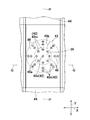
- the elements on larger scale which looked at a part of absorption pad from the skin opposing surface side.
- the elements on larger scale of arrow VIII in FIG. The elements on larger scale of the 1st end zone side of an absorption pad.
- the following embodiments relate to the absorbent pad for men shown in FIGS. 1 to 14, and include not only the essential configuration of the invention, but also optional and preferable configurations.
- First Embodiment 1 to 9 show an example of a first embodiment of an absorbent pad 10 according to the present invention.
- FIG. 1 omits the deformation guiding portion 40 for the convenience of description
- FIGS. 1 to 5 show a state in which the contraction force of the cuff elastic element 53 described later does not act.
- the absorbent pad 10 has a transverse direction X, a longitudinal direction Y, a thickness direction Z, a skin opposing surface and a non-skin opposing surface opposite to the skin, and a longitudinal direction Y intersecting with each other.
- a longitudinal center line P bisecting the dimension of the absorbent pad 10 in the lateral direction X in parallel with the transverse center line Q bisecting the dimension of the absorbent pad 10 in the longitudinal direction Y in parallel to the transverse direction X Have.
- Absorbent pad 10 is formed symmetrically with respect to longitudinal center line P, and has curved first and second edges 10a and 10b opposed to each other in longitudinal direction Y, and both sides extending in the longitudinal direction Y therebetween. It is defined by the edges 10c and 10d.
- the absorbent pad 10 has a first end 11 located on the side of the first end 10 a, a second end 12 located on the side of the second end 10 b, and an intermediate area located between them. And 13.
- the second end 10 b has a gentler curve than the first end 10 a, and the dimension in the lateral direction X is larger, and the second end area 12 is wider than the first end area 11.
- the absorbent pad 10 has a substantially triangular shape in a plan view, in which the distance between the side edges 10c and 10d gradually increases from the side of the first edge 10a toward the side of the second edge 10b.
- the absorbent pad 10 may have various known planar shapes such as a circular shape and a rectangular shape as long as the effects of the present invention described later can be obtained, in addition to the planar shape.
- the first end area 11 of the absorbent pad 10 is in contact with the crotch of the wearer (below the scrotum 49), the middle area 13 is in contact with the penis 48, and the second end area 12 is in contact with the lower abdomen 47. Be touched.
- the absorbent pad 10 has both side areas 14 located on the side edges 10 c and 10 d side in the lateral direction X and a central area 15 located between the both side areas 14. .
- the absorbent pad 10 has a pad body 20 in its entire form, a pair of barrier cuff sheets 50 disposed on both side areas 14 on the skin-facing surface of the pad body 20, and first and second end areas 11 of the pad body 20. , 12, and includes a pair of cover sheets 60 fixed to the skin facing surface side of the barrier cuff sheet 50.
- the cover sheet 60 is a first cover sheet 61 that covers the pad body 20 located between the barrier cuff sheets 50 in the first end area 11 and a pad body located between the barrier cuff sheets 50 in the second end area 12.
- 20 has a second cover sheet 62 covering it.
- the pad main body 20 is between the body side liner 21 located on the skin facing surface side, the back sheet 22 located on the non-skin facing surface side, and the body side liner 21 and the back sheet 22. And a liquid-absorbent core 23 located. Further, a cushion sheet 24 is optionally disposed between the body side liner 21 and the liquid absorbent core 23.
- the body side liner 21 and the cushion sheet 24 are formed of a liquid non-woven fabric having liquid permeability.
- the back sheet 22 is formed of a liquid-impervious or liquid-impervious fibrous nonwoven fabric, a breathable plastic film, or a laminate sheet thereof.
- the absorbent core 23 is substantially conformal to the pad body 20 and is made of a mixture comprising wood fluff pulp, absorbent polymer particles (SAP), and optionally thermoplastic fibers. It includes a core material and a liquid diffusive sheet such as tissue paper which encloses the core material.
- a liquid diffusive sheet such as tissue paper which encloses the core material.
- a sheet coated with a water-soluble water-soluble antibacterial agent can be used.
- an antibacterial effect can be obtained by the contact of body fluid such as urine with the liquid diffusive sheet, and if the antibacterial agent is colored, coloring is performed from the body side liner 21 side.
- the portion where the deformation guiding portion 40 is formed looks darker in color than the portion where the deformation guiding portion 40 is not formed, it can be used as an alignment mark.
- the antimicrobial agent include cetyl pyridinium chloride (CPC), benzalkonium chloride and the like.
- the dimension L1 of the pad body 20 in the longitudinal direction Y is about 160 to 300 mm
- the dimension W1 in the transverse direction X is about 120 to 300 mm.
- the dimension R1 in the direction Z is about 3.0 mm or less
- the dimension R2 in the thickness direction Z of the deformation inducing portion 40 is about 0.3 mm or less.
- the back side of the absorbent pad 10, that is, the non-skin facing side of the back sheet 22, is formed of a pressure-sensitive adhesive for attaching the absorbent pad 10 to clothes such as underwear.
- a plurality of barbs 30 extending in the direction Y are disposed.
- the fastening portion 30 has a central fastening portion 31 extending from the first end zone 11 to the second end zone 12 intersecting the transverse center line Q, and a lateral direction X of the central fastening portion 31 on the second end zone 12 side.
- the side fastening portions 32 located on both sides of the The central fastening portion 31 and the side fastening portions 32 are covered with a plastic or non-woven fabric separator 33.
- a plurality of deformation guiding portions 40 are arranged at intervals in the longitudinal direction Y and the lateral direction X only in the intermediate region 13 . Moreover, in other words, in the pad body 20, in the lateral direction X, the plurality of deformation guiding portions 40 are disposed only in the central region 15. The plurality of deformation guiding portions 40 define a deformation guiding area 43 in which the pad body 20 is easily deformed.
- the deformation guiding area 43 is disposed in the place where the barrier cuff sheet 50 and the cover sheet 60 do not exist, and the deformation guiding part 40 is not present in the place where the barrier cuff sheet 50 and the cover sheet 60 exist.
- Area 44 is arranged. That is, the pad body 20 has the nonexistent region 44 outside the deformation induction region 43 in the longitudinal direction Y and the lateral direction X.
- five deformation guiding portions 40 are arranged at intervals in the lateral direction X at the outermost side in the longitudinal direction Y of the deformation guiding area 43, and four deformation guiding portions 40 are provided inside thereof. Are spaced in the lateral direction X. Inside them, five deformation guides 40 and four deformation guides 40 are arranged alternately in the longitudinal direction Y in the lateral direction.
- one deformation guiding portion 40a arbitrarily selected from the plurality of deformation guiding portions 40 is another two deformation guiding portions 40b and 40c are arranged side by side in the longitudinal direction Y, and are arranged side by side in the lateral direction X with respect to the other two deformation guiding portions 40d and 40e, and the other two deformation guiding portions 40f and 40g (40h, 40h For 40i), they are arranged side by side in a direction inclined with respect to the vertical direction Y and the horizontal direction X (hereinafter simply referred to as “inclination direction”).
- the separation dimension of the deformation guiding portions 40 aligned in the longitudinal direction Y is preferably about 5 to 50 mm, and the separation dimension of the deformation guiding portions 40 aligned in the lateral direction X is preferably about 5 to 30 mm, and deformations aligned in the inclination direction
- the separation dimension of the guide portion 40 is preferably about 7 to 60 mm.
- the ratio of the dimension L2 in the longitudinal direction Y of the deformation induction area 43 to the dimension L1 in the longitudinal direction Y of the absorbent pad 10 is about 20.0 to 60.0%, and the dimension in the lateral direction X of the absorbent pad 10
- the ratio of the dimension W2 in the lateral direction X of the deformation induction area 43 to W1 is about 15.0 to 45.0%.
- each deformation guiding portion 40 has a cross shape in which a first line 41 extending in the longitudinal direction Y and a second line 42 extending in the lateral direction X intersect with each other. Further, as shown in FIG. 5, in the deformation guiding area 43, the dimension L3 of the central fastening portion 31 in the longitudinal direction Y is larger than the dimension L2 of the longitudinal direction Y.
- the deformation guiding portion 40 is formed, for example, by pin embossing (or pin debossing) processing, and more specifically, by pressing the body side liner 21 with the boss (pin) toward the back sheet 22, the body side liner 21. , The back sheet 22, the absorbent core 23, and the cushion sheet 24. Therefore, each deformation guiding portion 40 has a smaller dimension R2 in the thickness direction Z and higher rigidity as compared with the dimension R1 in the thickness direction Z of the peripheral portion 46 deviated from the deformation guiding portion 40.
- the barrier cuff sheet 50 has a shape that extends in the longitudinal direction Y and gradually tapers from the second end 10b to the first end 10a. It can be formed from a liquid impervious fibrous nonwoven fabric.
- the barrier cuff sheet 50 is fixed to the pad body 20 and has fixed edges fixed to the pad body 20 at the first and second end zones 11 and 12 with the proximal edge 57 extending along the side edges 10c and 10d. 58 and a sleeve-like free edge 52 (distal edge) formed by folding back the inner edges 10c, 10d of the barrier cuff sheet 50, extending in the longitudinal direction Y between the fixed ends 58; Have.
- the proximal edge portion 57 is a part of the seal portion 18, and the fixed end portions 58 excluding the both end portions 53 a of the cuff elastic element 53 are also a portion of the seal portion 18.
- the barrier cuff sheet 50 is fixed to the pad main body 20 via the seal portion 18 in its entire outer periphery except for the free edge 52 and both end portions 53 a of the cuff elastic element 53.
- a string-like or strand-like cuff elastic element 53 extending in the longitudinal direction Y is stretchably fixed in an extensible state, and at both side regions 14 of the pad body 20, the longitudinal direction Y A contractible area (side elastic part) 54 which can be expanded and contracted is formed.
- Two cuff elastic elements 53 are arranged at intervals of 3.0 to 15.0 mm in one side in the lateral direction X.
- the free edge 52 is separated from the skin-facing surface of the body-side liner 21 by the contraction action of the cuff elastic element 53 in the worn state, and has a pair of barrier cuffs (three-dimensional cuffs) for preventing lateral leakage of excrement such as urine. It is formed.
- the elastic material 53 has a thickness (diameter) of, for example, about 310 to 1240 dtex and is fixed in a state of being stretched about 1.2 to 2.0 times from a contracted or relaxed state, for example. Can be used.
- the barrier cuff sheet 50 has a contraction area 54 in which the cuff elastic element 53 is disposed in an extended state, and a non-contraction area 55 in which the cuff elastic element 53 is disposed in a substantially inelastic state (FIG. 2) , See FIGS. 9 and 10).
- the barrier cuff sheet 50 overlaps with parts of the first and second cover sheets 61 and 62, and is fixed to the cover sheet 60 at the overlapping part.
- the contraction area 54 of the free edge 52 contracts to substantially raise the barrier cuff.
- substantially deelasticized with respect to the non-shrinkage area 55 means that the cuff elastic element 53 is present in the area but does not express contraction at all and slightly contractility. And.
- the non-bonded portion 53b where the bonding by the seal portion 18 is not performed is located at the both end portions 53a of the cuff elastic element 53 in the existing region of the both ends 53a of the cuff elastic element 53.
- the dimension W3 in the lateral direction X of the non-joined portion 53b is 1.0 to 10.0 mm.
- the first and second cover sheets 62 are formed of a non-elastic sheet material, for example, a liquid-impervious or liquid-impervious fibrous nonwoven fabric, an air-permeable plastic film, or a laminate sheet thereof. Can.
- the first and second cover sheets 62 each have an inner edge 61 a, 62 a extending in the lateral direction X between the inner edges 50 a of the barrier cuff sheet 50.
- Each of the first and second cover sheets 61 and 62 is fixed to the body side liner 21 at both ends in the longitudinal direction Y and at the center in the transverse direction X, as shown in FIGS. 9 and 10. It has a portion 68, 69 and a non-fixed portion 68a, 69a not fixed to the body side liner 21 located inside the central fixed portion 68, 69 in the longitudinal direction Y.
- the non-fixed portions 68a and 69a overlap the liquid-absorbent core 23 in plan view.
- the contraction area 54 is contracted to extend linearly in the longitudinal direction Y, and the barrier cuff sheet 50 is erected to thereby form the first and second
- the non-fixed portions 68 a and 69 a of the cover sheets 61 and 62 are separated from the body side liner 21, and a first for storing excrement between the first and second cover sheets 61 and 62 and the body side liner 21.
- a space 72 and a second space 73 are formed respectively.
- the pad body 20 has a flat plate-like deformation induction area 43, a non-existence area 44 extending linearly, and a deformation area 45 between the deformation induction area 43 and the non-existence area
- the deformation induction area 43 is at the bottom and the absence area 44 is at the side.
- the first space portion 72 and the second space portion 73 gradually increase in the thickness direction Z from the inner edge portions 61a, 62a toward the first and second end edges 10a, 10b by presenting the form such as this. The dimensions are smaller.
- the inside edge 50 a of the barrier cuff sheet 50 and the inside edges 50 a of the first and second cover sheets 61 and 62 define an insertion opening 63 into which the wearer's penis 48 is inserted. .
- the penis 48 is inserted into the insertion opening 63.
- the scrotum 49 abuts on the top surface of the first end zone 11 or is located away from the top surface.
- the bottom portion formed of the deformation induction area 43 in the middle area 13 and the central area 15, and the non-recession in the both side areas 14 and the first and second end areas 11 and 12.
- a housing space S is formed which can be housed to enclose the penis 48, which is defined by the side formed from the presence area 44.
- the excrement excreted during wearing is absorbed and held mainly by the peripheral portion 46 between the deformation guiding portion 40 and the deformation guiding portion 40 in the liquid absorbing core 23, and the whole of the liquid absorbing core 23. Diffused.
- the rigidity of the deformation guiding portion 40 is high, and the rigidity of the peripheral portion 46 deviated from the deformation guiding portion 40 is low. And the peripheral portion 46 between the deformation inducing portion 40 and the deformation inducing portion 40 is bent.
- the deformation guiding portion 40 is disposed in the intermediate region 13 and the central region 15 at intervals in the longitudinal direction Y and the lateral direction X, the rigidity of the deformation guiding region 43 is absent It is higher than the rigidity of 44, and it is easy to maintain the surface shape (plate-like shape) of the deformation induction area 43 before wearing. Therefore, it is easy to apply the middle zone 13 and the central zone 15 to clothes such as underwear.
- the central area 13 and the deformation guiding portion 40 of the central area 15 can be used as a mark, so that the portion in contact with the penis 48 can be easily understood and alignment is easy.
- the intermediate region 13 and the central region 15 are deformed by the deformation guiding portion 40 according to the posture of the wearer. For this reason, even if the posture of the wearer changes, there is no sense of discomfort. Moreover, by the plurality of deformation guiding portions 40 being positioned between the contraction areas 54, the pad body 20 is easily deformed into a curved shape along the wearer's body.
- the excrement when the excrement is excreted in the absorbent pad 10, the excrement is held by the peripheral portion 46 between the deformation inducing portion 40 and the deformation inducing portion 40 in the absorbent core 23, and the thickness direction of the portion
- the deformation guiding portion 40 is disposed around the portion, so that the dimension in the thickness direction Z can be suppressed from becoming larger than necessary, and it is not visible from the outside.
- the absorbent pad 10 disclosed in Patent Document 1 when the continuously extending groove portion is formed in the pad main body 20, a large gather can be formed in the pad main body 20, and the large gather may cause leakage of excrement.
- the plurality of deformation guiding portions 40 are arranged at intervals in the longitudinal direction Y and the transverse direction X, generation of large gathers is suppressed, and the excrement leaks. While being able to prevent that and being inconspicuous from the outside, it can suppress that a wrinkles is formed in clothes.
- one deformation guiding portion 40a selected from the plurality of deformation guiding portions 40 is in each of the longitudinal direction Y, the lateral direction X, and the inclination direction. , Lined up with another two deformation guides 40.
- the deformation induction arranged in the vertical direction Y The pad body 20 is deformed at the peripheral portion 46 between the deformation guiding portions 40 arranged in the longitudinal direction Y, such as the peripheral portion 46 between the portions 40a and 40b or the peripheral portion 46 between the deformation guiding portions 40a and 40c
- the guiding area 43 is easily deformed along the lateral direction X.
- the pad body 20 is deformed at the peripheral portion 46 between the deformation guiding portions 40 arranged in the lateral direction X, such as the peripheral portion 46 of the peripheral portion 46 or the peripheral portion 46 between the deformation guiding portions 40a and 40d, Transforms easily along Y.
- the deformation guiding portions 40a, 40f, 40g (40a, 40h, 40i) arranged in the inclining direction when force is applied to the pad main body 20 from the inclining direction by the deformation guiding portions 40a, 40f, 40g (40a, 40h, 40i) arranged in the inclining direction, the deformation guiding portions 40a, 40f (40a) arranged in the inclining direction. , 40h), or the peripheral portion 46 between the deformation guiding portions 40a, 40g (40a, 40i), etc., the pad body 20 is deformed at the peripheral portion 46 between the deformation guiding portions 40 aligned in the inclination direction
- the deformation induction area 43 is easily deformed along the inclination direction.
- intermediate region 13 and the central region 15 are easily deformed in four different directions (longitudinal direction Y, lateral direction X and inclined directions orthogonal to each other), even if the posture of the wearer changes, In response, intermediate region 13 and central region 15 deform easily.
- each deformation guiding portion 40 has a cross shape in which the first line 41 extending in the longitudinal direction Y and the second line 42 extending in the lateral direction X intersect.
- a force is concentrated and applied to the peripheral portion 46 between the deformation inducing portions 40, whereby the deformation inducing region 43 is easily deformed along the longitudinal direction Y and the lateral direction X .
- the plurality of deformation guiding parts are circular, since the force is dispersedly applied to the peripheral portion 46 between the deformation guiding parts, the deformation is not so largely deformed as compared with the cross-shaped deformation guiding part 40.
- this absorbent pad 10 since the dimension in the thickness direction Z is 3.0 mm or less, it is relatively thin and becomes more compact when it is bent. Also, even while wearing, it is not noticeable from the outside. Moreover, it integrates with the clothes and the absorbent pad 10 is deformed along the deformation of the clothes.
- the deformation guiding portion 40 is disposed in the entire area of the intermediate area 13 and the central area 15, the entire area of the intermediate area 13 and the central area 15 defining the accommodation space S can be deformed is there.
- the central fastening portion 31 extends to the outside in the longitudinal direction Y more than the deformation guiding area 43, so the pad body 20 outside the deformation guiding area 43 is integrated with the clothes and is bent. For this reason, while the absorption pad 10 adapts to the undergarment, the pad main body 20 does not suddenly bend at the boundary between the deformation induction region 43 where the deformation induction portion 40 exists and the nonexistence region 44 where the deformation induction portion 40 does not exist. It can be gently curved.
- the absorbent pad of this embodiment According to 10, by setting the both end portions 53a of the cuff elastic element 53 as the non-joining portions 53b, the rigidity can be reduced, and the entire pad can be deformed into a curved shape along the body.
- the number per unit area of the deformation guiding portions 40 is sparse in the outside in the longitudinal direction Y in the deformation guiding region 43 in which the plurality of deformation guiding portions 40 are arranged. On the other hand, it is dense in the center.
- the area of the deformation induction area 43 of the absorbent pad 10 of the present embodiment and the area of the deformation induction area 43 of the absorbent pad 10 of the first embodiment are the same, in the longitudinal direction Y, Outside, only three deformation guiding parts 40j (40), 40k (40), 40l (40) are arranged in the lateral direction X, and low density areas 44a are defined at both ends in the longitudinal direction Y of the deformation inducing area 43
- the deformation guiding part 40 similar to the deformation guiding area 43 of the first embodiment is disposed inside the longitudinal direction Y of the deformation guiding parts 40j, 40k and 40l, and the high density area 44b is defined. It is done.
- the pad main body 20 can be gently bent without being sharply bent at the boundary between the deformation guiding area 43 where the deformation guiding part 40 exists and the nonexistence region 44 where the deformation guiding part 40 does not exist.
- the number of deformation guiding portions 40 at both ends in the vertical direction Y of the pad body 20 decreases, so the deformation guiding region 43 gradually becomes horizontal as it goes to the outside in the vertical direction Y.
- the dimension in the direction X becomes smaller.
- the pad main body 20 is gently bent without being sharply bent at the boundary between the deformation inducing region 43 where the deformation inducing portion 40 exists and the nonexistence region 44 where the deformation inducing portion 40 does not exist. be able to.
- one deformation guiding portion 40s (40) is disposed at the center in the longitudinal direction Y, and a plurality of deformation guiding portions 40 are provided around the deformation guiding portion 40.
- the deformation guiding unit 40 of the second embodiment is disposed.
- a low density region 45a in which the number of deformation guiding portions 40m per unit area is sparse is defined, while the central deformation guiding portion In the distal portion 38 of 40 s, a plurality of deformation guiding portions 40 are arranged such that a high density area 45 b in which the number of deformation guiding portions 40 n per unit area is dense is defined.
- the deformation guiding portion 40 is arranged so as to be sparse at the proximal portion 39 of the central deformation guiding portion 40, it is difficult to deform, while the deformation guiding portion 40 of the center is The distal portion is easily deformed because the deformation guiding portion 40 is disposed so as to be dense. For this reason, the proximal part 39 centering on the deformation
- the deformation induction areas 43 are arranged in the inclination direction in the deformation induction portions 40m and 40n arranged in the direction in which the deformation induction portion 40s inclines. Easily transform into
- each deformation guiding portion 40 the cross shape in which the first line 41 extending in the longitudinal direction Y and the second line 42 extending in the lateral direction X intersect is described.
- the present invention is not limited thereto, and each deformation guiding portion 40 may have a known shape such as a circular shape.
- the deformation guiding portion 40 is formed by pin embossing (or pin debossing) processing, and the rigidity of the deformation guiding portion 40 is higher than the rigidity of the peripheral portion 46 removed from the deformation guiding portion 40.
- the present invention is not limited thereto, and the deformation guiding portion 40 is formed as a non-existing region where the liquid absorbing core 23 does not exist, or the mass per unit area in the deformation guiding portion 40 is the unit area of the peripheral portion 46
- the rigidity of the deformation / induction portion 40 may be smaller than the rigidity of the peripheral portion 46 so as to be smaller than the mass of the contact. In the wearing state when such a deformation guiding portion 40 is used, the deformation guiding region 43 deforms along the first line 41 and the second line 42 of the low rigidity deformation guiding portion 40.
- the plurality of deformation guiding portions 40 are arranged at intervals in the longitudinal direction Y, the horizontal direction X, and the inclination direction with respect to the arbitrary deformation guiding portions 40.
- the present invention is not limited thereto.
- the non-joined portions 53b not joined by the seal portion 18 are respectively located at both end portions 53a of the cuff elastic element 53.
- the present invention is not limited thereto, and the non-joining portion 53b which is not joined by the seal portion 18 may be located at least only at the end 53a of the cuff elastic element 53 on the second end region 12 side.
Landscapes
- Health & Medical Sciences (AREA)
- Epidemiology (AREA)
- Engineering & Computer Science (AREA)
- Biomedical Technology (AREA)
- Heart & Thoracic Surgery (AREA)
- Vascular Medicine (AREA)
- Life Sciences & Earth Sciences (AREA)
- Animal Behavior & Ethology (AREA)
- General Health & Medical Sciences (AREA)
- Public Health (AREA)
- Veterinary Medicine (AREA)
- Absorbent Articles And Supports Therefor (AREA)
Abstract
着用者の姿勢に応じて変形する吸収パッドを提供する。 吸収パッド(10)は、縦方向(Y)及びそれに交差する横方向(X)と、肌対向面及びその反対側の非肌対向面とを有し、吸液性コア(23)を有するパッド本体(20)を含む男性用のものである。パッド本体(20)は、縦方向(Y)において互いに離隔対向する第1端域(11)及び第2端域(12)と、第1及び第2端域間に位置する中間域(13)とを有する。吸収パッド(10)は、中間域(13)においてのみ、複数の変形誘導部(40)が、縦方向(Y)と横方向(X)とにおいて互いに間隔を空けて配置されている。パッド本体(20)は、横方向(X)において互いに離隔対向する両側域(14)をさらに有する。両側域(14)は、縦方向(Y)へ伸縮可能な収縮域(サイド弾性部)(54)を有する。変形誘導部(40)は、収縮域(54)の間に位置している。
Description
本発明は、男性用の吸収パッドに関する。
従来、縦方向及びそれに交差する横方向と、肌対向面及びその反対側の非肌対向面とを有し、吸液性コアを有するパッド本体を含む男性用の吸収パッドは公知である。例えば、特許文献1には、縦方向において互いに離隔対向する第1端域及び第2端域と、第1及び第2端域間に位置する中間域とを有するパッド本体を備える吸収パッドが開示されている。
この吸収パッドは、縦軸と交差して斜めに延びる第1溝と、縦軸と交差し、かつ、第1溝と交差する方向へ延びる第2軸とを有する折曲誘導溝を備えている。
特許文献1に開示された吸収パッドでは、縦軸と交差して斜めに延びる第1及び第2溝に沿って吸収パッドが変形する。よって、この吸収パッドは、一定のカップ形状に変形するため、着用者の姿勢が変化したときであっても、一定のカップ形状を維持し、これによって着用するとき及び着用中に着用者が違和感を覚えるおそれがあるとともに、着用中に吸収パッドを装着していることが外部からわかるおそれがあった。また、下着等の着衣をずらした状態では、吸収パッドによって下着に皺が形成されやすい課題があった。さらに、男性用の吸収パッドは、女性用のように下着の股間部に合わせて装着するものではなく、身体の前側に偏って装着するため、位置あわせが容易ではない課題があった。
本発明は、従来の吸収パッドの改良であって、着衣に皺が形成されにくく、位置あわせが容易であって、着用者の姿勢に応じて変形するとともに、外部から目立ちにくい吸収パッドの提供を課題にしている。
本発明は、縦方向及びそれに交差する横方向と、肌対向面及びその反対側の非肌対向面とを有し、吸液性コアを有するパッド本体を含む男性用の吸収パッドに関する。
本発明に係る吸収パッドによれば、前記パッド本体は、前記縦方向において互いに離隔対向する第1端域及び第2端域と、第1及び第2端域間に位置する中間域とを有し、前記中間域においてのみ、複数の変形誘導部が、前記縦方向と前記横方向とにおいて互いに間隔を空けて配置されている。
前記パッド本体は、前記横方向において互いに離隔対向する両側域をさらに有し、前記両側域は、前記縦方向へ伸縮可能なサイド弾性部を有し、前記変形誘導部は、前記サイド弾性部間に位置している。前記吸収パッドによれば、サイド弾性部間に変形誘導部が位置することによって、パッド本体が、着用者の身体に沿った湾曲した形状に変形し易くなる。
前記パッド本体は、前記肌対向面側に位置する透液性の身体側ライナと、非肌対向面側に位置する不透液性の裏面シートと、前記サイド弾性部を形成する一対のバリアカフシートと、前記バリアカフシートに前記縦方向へ収縮可能に取り付けられたカフ弾性体とを有し、前記身体側ライナと、前記裏面シートと、前記バリアカフシートとは、前記パッド本体の外周縁に沿うシールラインによって接合されており、前記カフ弾性体の少なくとも一方の端部の存在域において、前記シールラインによる接合がなされていない非接合部が位置する。前記吸収パッドによれば、カフ弾性体の両端部では剛性が高くなるため、該部分においては、身体に沿った湾曲した形状に成り難いところ、非接合部とすることで剛性を低くして、パッド全体を身体に沿った湾曲した形状に変形させることができ、ブリーフなどの身体に密着しやすい着衣に装着しても、不自然な変形や皺が外部から目立ちにくい。
前記パッド本体は、厚さ方向の寸法が3.0mm以下である。前記吸収パッドによれば、比較的に薄いため、折曲したときによりコンンパクトになる。また、着用中においても、外部から目立たない。
前記変形誘導部は、前記縦方向へ延びる第1ラインと、前記横方向へ延びる第2ラインとが交差してなる十字状である。前記吸収パッドによれば、縦方向及び横方向のそれぞれにおいて、変形誘導部の間の周辺部位に力が集中して加わり、これによって、変形誘導域が縦方向及び横方向に沿って容易に変形する。
前記変形誘導部は、前記縦方向及び前記横方向に対して傾斜する方向に並んで配置される。前記吸収パッドによれば、吸収パッドが、縦方向及び横方向に対して傾斜する方向に沿って容易に変形する。
前記吸収パッドは、複数の前記変形誘導部が配置された変形誘導域において、前記変形誘導部の単位面積当たりの数が前記縦方向の外側で疎になる。前記吸収パッドによれば、吸収パッドは、変形誘導部が存在する存在域と、変形誘導部が存在しない非存在域との境界で急に折れ曲がることなく、緩やかに湾曲する。
前記吸収パッドは、複数の前記変形誘導部が配置された変形誘導域は、前記縦方向の外側に向かうにつれて次第に前記横方向の寸法が小さくなる。前記吸収パッドによれば、前記吸収パッドは、変形誘導部が存在する存在域と、変形誘導部が存在しない非存在域との境界で急に折れ曲がることなく、緩やかに湾曲する。
前記パッド本体は、前記非肌対向面側に位置する粘着性の止着部をさらに有し、前記止着部は、前記変形誘導部が配置された変形誘導域よりも前記縦方向の外側へ延びる。前記吸収パッドによれば、変形誘導域の縦方向の外側において、止着部が着衣に貼りつくため、変形誘導部の外側まで着衣と一体となる。よって、変形誘導部が存在する存在域と、変形誘導部が存在しない非存在域との境界で、吸収パッドが急に折れ曲がることを抑えることができる。
本発明の一つ以上の実施形態に係る吸収パッドによれば、中間域においてのみ、複数の変形誘導部が、縦方向と横方向とに互いに間隔をあけて配置されているため、吸収パッドを着用するとき及び着用中において、着用者の姿勢等に応じて中間域が変形する。このため、着用するとき及び着用中に着用者が違和感を覚えるおそれがないとともに、着用中に吸収パッドを装着していることが外部からわかるおそれもない。また、下着等の着衣をずらした状態であっても、変形誘導部によって吸収パッドが変形するため、着衣に皺が形成されにくい。さらに、中間域においてのみ変形誘導部が配置されているため、着用するときに変形誘導部が目印となることによって位置あわせが容易である。
図面は、本発明の特定の実施の形態を示し、発明の不可欠な構成ばかりでなく、選択的及び好ましい実施の形態を含む。
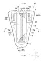
本発明の第1実施形態に係る吸収パッドを正面側から視た斜視図。
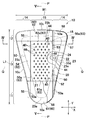
非肌対向面側から視た、各カフ弾性体の最大伸長時(弾性材料の収縮作用によるギャザーがなくなる程度)まで縦方向及び横方向に伸展した吸収パッドの一部破断平面図。
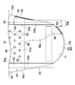
吸収パッドの一部破断底面図。
図2のIV-IV線に沿う断面図。
図1のV-V線に沿う断面図。
着用状態における吸収パッドの縦中心線に沿う断面図。
吸収パッドの一部を肌対向面側から視た部分拡大図。
図7における矢視VIIIの部分拡大図。
吸収パッドの第1端域側の部分拡大図。
吸収パッドの第2端域側の部分拡大図。
カフ弾性要素の収縮力が作用している吸収パッドの縦中心線に沿う断面図。
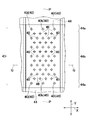
第2実施形態に係る吸収パッドの図7と同様の部分拡大図。
第3実施形態に係る吸収パッドの図7と同様の部分拡大図。
第4実施形態に係る吸収パッドの図7と同様の部分拡大図。
下記の実施の形態は、図1~図14に示す男性用の吸収パッドに関し、発明の不可欠な構成ばかりではなく、選択的及び好ましい構成を含む。
<第1実施形態>
図1~図9は、本発明に係る吸収パッド10の第1実施形態の一例を示す。なお、図1には、説明の便宜のため変形誘導部40を省略してあり、図1~図5には、後記のカフ弾性要素53の収縮力が作用していない状態を示す。図1~図4を参照すると、吸収パッド10は、互いに交差する横方向Xと、縦方向Yと、厚さ方向Zと、肌対向面及びその反対側の非肌対向面と、縦方向Yに平行して吸収パッド10の横方向Xの寸法を二等分する縦中心線Pと、横方向Xに平行して吸収パッド10の縦方向Yの寸法を二等分する横中心線Qとを有する。吸収パッド10は、縦中心線Pに関して対称に形成されるとともに、縦方向Yにおいて互いに対向する曲状の第1端縁10a及び第2端縁10bと、それらの間において縦方向Yへ延びる両側縁10c,10dとによって画定される。
図1~図9は、本発明に係る吸収パッド10の第1実施形態の一例を示す。なお、図1には、説明の便宜のため変形誘導部40を省略してあり、図1~図5には、後記のカフ弾性要素53の収縮力が作用していない状態を示す。図1~図4を参照すると、吸収パッド10は、互いに交差する横方向Xと、縦方向Yと、厚さ方向Zと、肌対向面及びその反対側の非肌対向面と、縦方向Yに平行して吸収パッド10の横方向Xの寸法を二等分する縦中心線Pと、横方向Xに平行して吸収パッド10の縦方向Yの寸法を二等分する横中心線Qとを有する。吸収パッド10は、縦中心線Pに関して対称に形成されるとともに、縦方向Yにおいて互いに対向する曲状の第1端縁10a及び第2端縁10bと、それらの間において縦方向Yへ延びる両側縁10c,10dとによって画定される。
吸収パッド10は、縦方向Yにおいて、第1端縁10a側に位置する第1端域11と、第2端縁10b側に位置する第2端域12と、それらの間に位置する中間域13とを有する。第2端縁10bは、第1端縁10aよりも緩やかな曲状であって、横方向Xの寸法が大きく、第2端域12は、第1端域11よりも幅広である。吸収パッド10は、第1端縁10a側から第2端縁10b側へ向けて両側縁10c,10dの間隔が徐々に広くなる、平面視が略三角形状である。吸収パッド10は、かかる平面視形状のほかに、後記の本発明の効果を奏する限りにおいて、円形や矩形など各種公知の平面形状であってもよい。図6を参照すると、吸収パッド10の第1端域11は着用者の股下部(陰嚢49の下方)に、中間域13は陰茎48に、第2端域12は下腹部47にそれぞれ当接される。また、吸収パッド10は、図1及び図2に示すように、横方向Xにおいて、両側縁10c,10d側に位置する両側域14と、両側域14の間に位置する中央域15とを有する。
吸収パッド10は、その全体形態をなすパッド本体20と、パッド本体20の肌対向面における両側域14に配置された一対のバリアカフシート50と、パッド本体20の第1及び第2端域11,12に配置され、バリアカフシート50の肌対向面側に固定された一対のカバーシート60とを含む。カバーシート60は、第1端域11において、バリアカフシート50間に位置するパッド本体20を被覆する第1カバーシート61と、第2端域12において、バリアカフシート50間に位置するパッド本体20を被覆する第2カバーシート62とを有する。パッド本体20と、バリアカフシート50及びカバーシート60とは、カフ弾性要素53の両端部53aを除き、吸収パッド10の外周縁に沿って延びる、熱溶着手段によって形成されたシール部18(シールライン)によって互いに積層された状態で固定される。また、吸収パッド10は、図3に示すように、パッド本体20の吸液性コア23の外周縁から延出する両シート50,60をシール部18によって互いに接合することによって形成された、吸液性コア23の両側縁23cの横方向Xの外側において縦方向Yへ延びるサイドフラップと、吸液性コア23の両端縁23a,23bの縦方向Yの外側において横方向Xへ延びるエンドフラップとを有する。
<パッド本体>
パッド本体20は、図2に示すように、肌対向面側に位置する身体側ライナ21と、非肌対向面側に位置する裏面シート22と、身体側ライナ21と裏面シート22との間に位置する吸液性コア23とを含む。また、身体側ライナ21と吸液性コア23との間には、オプションとして、クッションシート24が配置される。
パッド本体20は、図2に示すように、肌対向面側に位置する身体側ライナ21と、非肌対向面側に位置する裏面シート22と、身体側ライナ21と裏面シート22との間に位置する吸液性コア23とを含む。また、身体側ライナ21と吸液性コア23との間には、オプションとして、クッションシート24が配置される。
身体側ライナ21及びクッションシート24は、透液性を有する繊維不織布から形成されている。裏面シート22は、難透液性又は不透液性の繊維不織布、通気性プラスチックフィルム又はそれらのラミネートシートから形成されている。
吸液性コア23は、パッド本体20とほぼ同形に賦型されたものであって、木材フラッフパルプ、吸収性ポリマー粒子(SAP)、オプションとして熱可塑性繊維を含む混合物から形成された吸収性の芯材と、芯材を包被するティッシュペーパ等の液拡散性シートとを含む。液拡散性シートには、水に可溶な水溶性抗菌剤を塗布したものを使用することができる。このような液拡散性シートを使用したときには、尿等の体液が液拡散性シートに接することで抗菌効果が得られるとともに、抗菌剤が着色されたものであれば、身体側ライナ21側から着色された液拡散シートが明確に視認され、変形誘導部40を形成した部分は、変形誘導部40を形成していない部分よりも色が濃く見えるため、位置あわせの目印とすることができる。抗菌剤としては、例えば、塩化セチルピリジニウム(CPC)、塩化ベンザルコニウム等が挙げられる。
パッド本体20の縦方向Yの寸法L1は約160~300mmであり、横方向Xの寸法W1は約120~300mmであり、図5に示す、変形誘導部40から外れた周辺部位46の厚さ方向Zの寸法R1は約3.0mm以下であり、変形誘導部40の厚さ方向Zの寸法R2は約0.3mm以下である。これらのような寸法R1,R2の差をつけた場合には、両者の剛性の相違によって、変形誘導域43を底とし、周辺部位46を側壁とするカップ形状が明確になる。
図3を参照すると、吸収パッド10の裏面側、すなわち、裏面シート22の非肌対向面側には、下着等の着衣に吸収パッド10を取り付けるための、感圧性接着剤から形成された、縦方向Yへ延伸びる複数条の止着部30を配置してある。止着部30は、横中心線Qと交差して第1端域11から第2端域12へ延びる中央止着部31と、第2端域12側において中央止着部31の横方向Xの両側に位置するサイド止着部32とを有する。中央止着部31及びサイド止着部32は、プラスチック製又は繊維不織布のセパレータ33で被覆される。
<変形誘導部>
図2及び図7を参照すると、パッド本体20は、縦方向Yにおいて、中間域13においてのみ複数の変形誘導部40が、縦方向Yと横方向Xとにおいて互いに間隔をあけて配置されている。また、言い方を変えると、パッド本体20は、横方向Xにおいて、中央域15においてのみ複数の変形誘導部40が配置されている。複数の変形誘導部40によって、パッド本体20が容易に変形する変形誘導域43が画定される。この実施形態では、バリアカフシート50及びカバーシート60が存在しない個所に変形誘導域43を配置してあり、バリアカフシート50及びカバーシート60が存在する個所に変形誘導部40が存在しない非存在域44が配置される。すなわち、パッド本体20は、縦方向Y及び横方向Xにおいて、変形誘導域43の外側に非存在域44を有している。
図2及び図7を参照すると、パッド本体20は、縦方向Yにおいて、中間域13においてのみ複数の変形誘導部40が、縦方向Yと横方向Xとにおいて互いに間隔をあけて配置されている。また、言い方を変えると、パッド本体20は、横方向Xにおいて、中央域15においてのみ複数の変形誘導部40が配置されている。複数の変形誘導部40によって、パッド本体20が容易に変形する変形誘導域43が画定される。この実施形態では、バリアカフシート50及びカバーシート60が存在しない個所に変形誘導域43を配置してあり、バリアカフシート50及びカバーシート60が存在する個所に変形誘導部40が存在しない非存在域44が配置される。すなわち、パッド本体20は、縦方向Y及び横方向Xにおいて、変形誘導域43の外側に非存在域44を有している。
この実施形態では、変形誘導域43の縦方向Yの最も外側には、5つの変形誘導部40を横方向Xへ間隔をあけて配置してあり、その内側には、4つの変形誘導部40を横方向Xへ間隔をあけて配置してある。それらの内側には、横方向に5つの変形誘導部40と、4つの変形誘導部40とを縦方向Yへ交互に配置してある。また、縦中心線Pと横中心線Qとが交差する中心Oの近位部39において、複数の変形誘導部40から任意に選択した1つの変形誘導部40aは、別の2つの変形誘導部40b,40cに対して縦方向Yに並んで配置され、別の2つの変形誘導部40d,40eに対して横方向Xに並んで配置され、別の2つの変形誘導部40f,40g(40h,40i)に対して、縦方向Y及び横方向Xに対して傾斜する方向(以下、単に「傾斜方向」と省略する)に並んでそれぞれ配置されている。縦方向Yへ並んだ変形誘導部40の離隔寸法は、約5~50mmが好ましく、横方向Xへ並んだ変形誘導部40の離隔寸法は、約5~30mmが好ましく、傾斜方向へ並んだ変形誘導部40の離隔寸法は、約7~60mmが好ましい。また、吸収パッド10の縦方向Yの寸法L1に対する、変形誘導域43の縦方向Yの寸法L2の割合は、約20.0~60.0%であり、吸収パッド10の横方向Xの寸法W1に対する、変形誘導域43の横方向Xの寸法W2の割合は、約15.0~45.0%である。
各変形誘導部40は、図8に示すように、縦方向Yへ延びる第1ライン41と、横方向Xへ延びる第2ライン42とが交差してなる十字状である。また、変形誘導域43は、図5に示すように、その縦方向Yの寸法L2よりも、中央止着部31の縦方向Yの寸法L3が大きい。
変形誘導部40は、例えば、ピンエンボス(またはピンデボス)加工によって形成され、より詳細には、ボス(ピン)で身体側ライナ21から、裏面シート22へ向かって加圧することによって、身体側ライナ21、裏面シート22、吸液性コア23及びクッションシート24に形成される。そのため、各変形誘導部40は、変形誘導部40から外れた周辺部位46の厚さ方向Zの寸法R1と比較し、厚さ方向Zの寸法R2が小さくて剛性が高い。
<バリアカフシート>
バリアカフシート50は、図1及び図2に示すように、縦方向Yへ延び、第2端縁10bから第1端縁10aへ向かって次第に先細りとなる形状であって、難透液性又は不透液性の繊維不織布から形成することができる。バリアカフシート50は、パッド本体20に固定され、両側縁10c,10dに沿って延びる近位縁部57と、第1及び第2端域11,12においてパッド本体20に固定された固定両端部58と、固定両端部58の間において縦方向Yへ延びる、バリアカフシート50の内側縁10c,10dを内側へ折り返すことによって形成されたスリーブ状の自由縁部52(遠位縁部)とを有する。近位縁部57は、シール部18の一部であり、カフ弾性要素53の両端部53aを除いた固定両端部58も、シール部18の一部である。換言すれば、バリアカフシート50は、自由縁部52と、カフ弾性要素53の両端部53aとを除くその外周全体がシール部18を介してパッド本体20に固定されている。
バリアカフシート50は、図1及び図2に示すように、縦方向Yへ延び、第2端縁10bから第1端縁10aへ向かって次第に先細りとなる形状であって、難透液性又は不透液性の繊維不織布から形成することができる。バリアカフシート50は、パッド本体20に固定され、両側縁10c,10dに沿って延びる近位縁部57と、第1及び第2端域11,12においてパッド本体20に固定された固定両端部58と、固定両端部58の間において縦方向Yへ延びる、バリアカフシート50の内側縁10c,10dを内側へ折り返すことによって形成されたスリーブ状の自由縁部52(遠位縁部)とを有する。近位縁部57は、シール部18の一部であり、カフ弾性要素53の両端部53aを除いた固定両端部58も、シール部18の一部である。換言すれば、バリアカフシート50は、自由縁部52と、カフ弾性要素53の両端部53aとを除くその外周全体がシール部18を介してパッド本体20に固定されている。
バリアカフシート50の自由縁部52には、縦方向Yへ延びるストリング状又はストランド状のカフ弾性要素53が伸長状態で収縮可能に固定され、パッド本体20の両側域14には、縦方向Yへ伸縮可能な収縮域(サイド弾性部)54が形成される。カフ弾性要素53は、横方向Xの一方に、3.0~15.0mmの間隔で2本ずつ配置されている。自由縁部52は、着用状態において、カフ弾性要素53の収縮作用によって身体側ライナ21の肌対向面から離れ、尿等の排泄物の横漏れを防止するための一対のバリアカフ(立体カフ)が形成される。カフ弾性要素53には、例えば、太さ(径)が約310~1240dtexであって、収縮又は弛緩された状態から約1.2~2.0倍に伸長された状態で固定された弾性材料を用いることができる。
バリアカフシート50は、カフ弾性要素53が伸長状態で配置された収縮域54と、カフ弾性要素53が実質的に非弾性化された状態で配置された非収縮域55とを有する(図2、図9及び図10を参照)。バリアカフシート50は、第1及び第2カバーシート61,62の一部と互いに重なっており、その重なった部分においてカバーシート60に固定されている。吸収パッド10の着用状態では、自由縁部52の収縮域54が収縮することによって、実質的にバリアカフが起立する。ここで、非収縮域55に関して「実質的に非弾性化された」とは、カフ弾性要素53が該領域に存在するが、収縮性を全く発現しない状態と、僅かに収縮性を発現する状態とを含む。
カフ弾性要素53の両端部53aは、図9及び図10に示すように、カフ弾性要素53の両端部53aの存在域において、シール部18による接合がなされていない非接合部53bが位置する。非接合部53bの横方向Xの寸法W3は、1.0~10.0mmである。
<カバーシート>
第1及び第2カバーシート62は、非弾性のシート材料から形成されており、例えば、難透液性又は不透液性の繊維不織布、通気性のプラスチックフィルム又はそれらのラミネートシートから形成することができる。第1及び第2カバーシート62は、それぞれ、バリアカフシート50の内側縁部50aの間において横方向Xへ延びる内側縁部61a,62aを有する。
第1及び第2カバーシート62は、非弾性のシート材料から形成されており、例えば、難透液性又は不透液性の繊維不織布、通気性のプラスチックフィルム又はそれらのラミネートシートから形成することができる。第1及び第2カバーシート62は、それぞれ、バリアカフシート50の内側縁部50aの間において横方向Xへ延びる内側縁部61a,62aを有する。
第1及び第2カバーシート61,62のそれぞれは、図9及び図10に示すように、縦方向Yの両端であって、横方向Xの中央において、身体側ライナ21に固定された中央固定部68,69と、縦方向Yにおける中央固定部68,69の内側に位置する身体側ライナ21に固定されていない非固定部68a,69aとを有している。非固定部68a,69aは、平面視において、吸液性コア23と重なっている。
図11を参照すると、吸収パッド10を平坦な床や机等においた状態では、収縮域54が収縮されて縦方向Yにおいて直状に延び、バリアカフシート50が起立することによって第1及び第2カバーシート61,62の非固定部68a,69aが身体側ライナ21から離れ、第1及び第2カバーシート61,62と身体側ライナ21との間には、排泄物を貯留するための第1空間部72と第2空間部73とがそれぞれ形成される。この状態では、パッド本体20は、縦方向Yにおいて、平板状の変形誘導域43と、直状に延びる非存在域44と、変形誘導域43と非存在域との間の変形域45とによって、変形誘導域43を底部とし、非存在域44を側部としたカップ形状を呈する。パッド本体20がかかる形態を呈することによって、第1空間部72及び第2空間部73は、内側縁部61a,62aから第1及び第2端縁10a,10bに向かうに従って次第に厚さ方向Zの寸法が小さくなっている。
図2を参照すると、バリアカフシート50の内側縁部50aと第1及び第2カバーシート61,62の内側縁部50aとによって、着用者の陰茎48が挿入される挿入口63が画定される。
図6を参照すると、着用者が吸収パッド10を着用する際には、挿入口63に陰茎48を挿入する。陰嚢49は、第1端域11の上面に当接またはその上面から離れて位置する。パッド本体20には、着用する際、及び着用状態において、中間域13及び中央域15における変形誘導域43から形成された底部と、両側域14並びに第1及び第2端域11,12における非存在域44から形成された側部とによって画定された、陰茎48を包み込むように収容しうる収容スペースSが形成される。
着用中に排泄された排泄物は、主として、吸液性コア23における変形誘導部40と変形誘導部40との間の周辺部分46に吸収・保持されるとともに、吸液性コア23の全体に拡散される。また、着用者の姿勢が変化したとき、変形誘導部40の剛性が高く、変形誘導部40から外れた周辺部位46の剛性が低いため、それらの剛性の相違によって変形誘導部40がパッド本体20の変形の基点となり、変形誘導部40と変形誘導部40との間の周辺部位46が折れ曲がる。
この吸収パッド10によれば、変形誘導部40が、縦方向Y及び横方向Xにおいて間隔をあけて中間域13及び中央域15に配置されているため、変形誘導域43の剛性が非存在域44の剛性よりも高く、着用する前において変形誘導域43が面形状(板状の形状)を維持しやすい。よって、中間域13及び中央域15を下着等の着衣にあてがいやすい。しかも、吸収性パッド10を着用するときには、中央域13及び中央域15の変形誘導部40を目印にすることができるため、陰茎48を当接する部分がわかりやすく位置合わせが容易である。また、着用するとき及び着用後は、変形誘導部40によって、着用者の姿勢に応じて中間域13及び中央域15が変形する。このため、着用者の姿勢が変化しても、違和感を覚えることがない。しかも、収縮域54の間に複数の変形誘導部40が位置することによって、パッド本体20は、着用者の身体に沿った湾曲した形状に変形し易くなる。加えて、吸収パッド10に排泄物が排泄されたとき、吸液性コア23における変形誘導部40と変形誘導部40との間の周辺部位46によって排泄物が保持されて該部分の厚さ方向Zの寸法が大きくなるが、該部分の周囲には変形誘導部40が配置されているため、厚さ方向Zの寸法が必要以上に大きくなることを抑えることができ、外部から目立たない。また、特許文献1に開示された吸収パッド10のように、連続して延びる溝部がパッド本体20に形成されているときには、大きなギャザーがパッド本体20にでき、この大きなギャザーによって排泄物が漏れるおそれがあるところ、この吸収パッド10では、複数の変形誘導部40を縦方向Yと横方向Xとに互いに間隔をあけて配置されているため、大きなギャザーが発生することを抑え、排泄物が漏れることを防止することができるとともに外部から目立たず、着衣に皺が形成されるのを抑えることができる。
また、この吸収パッド10では、中心Oの近位部39において、複数の変形誘導部40から選択した1つの変形誘導部40aは、縦方向Yと、横方向Xと、傾斜方向とのそれぞれにおいて、別の2つの変形誘導部40に並ぶ。より具体的には、縦方向Yへ並ぶ変形誘導部40a,40b,40cによって、端縁10a,10bが互いに近づくようにパッド本体20に力が加えられたときには、縦方向Yに並んだ変形誘導部40a,40bの間の周辺部位46、又は変形誘導部40a,40cの間の周辺部位46等、縦方向Yへ並ぶ変形誘導部40の間の周辺部位46でパッド本体20が変形し、変形誘導域43が横方向Xに沿って容易に変形する。
また、横方向Xへ並ぶ変形誘導部40a,40d,40eによって、両側縁10cが互いに近づくようにパッド本体20に力が加えられたときには、横方向Xに並んだ変形誘導部40a,40dの間の周辺部位46、又は変形誘導部40a,40dの間の周辺部位46等、横方向Xへ並ぶ変形誘導部40の間の周辺部位46でパッド本体20が変形し、変形誘導域43が縦方向Yに沿って容易に変形する。
さらに、傾斜方向へ並ぶ変形誘導部40a,40f,40g(40a,40h,40i)によって、傾斜方向からパッド本体20に力が加えられたときには、傾斜方向に並んだ変形誘導部40a,40f(40a,40h)の間の周辺部位46、又は変形誘導部40a,40g(40a,40i)の間の周辺部位46等、傾斜方向へ並ぶ変形誘導部40の間の周辺部位46でパッド本体20が変形し、変形誘導域43が傾斜方向に沿って容易に変形する。しかも、中間域13及び中央域15は、異なる4方向(縦方向Y、横方向X、及び互いに直行する傾斜方向)へ容易に変形するので、着用者の姿勢が変化しても、その変化に応じて中間域13及び中央域15が容易に変形する。
また、この吸収パッド10によれば、各変形誘導部40は、縦方向Yへ延びる第1ライン41と、横方向Xへ延びる第2ライン42とが交差してなる十字状であるため、縦方向Y及び横方向Xのそれぞれにおいて、変形誘導部40の間の周辺部位46に力が集中して加わり、これによって、変形誘導域43が縦方向Y及び横方向Xに沿って容易に変形する。一方、複数の変形誘導部が円形状であるときには、変形誘導部の間の周辺部位46に力が分散して加わるため、十字状の変形誘導部40に比して、それほど大きく変形しない。
さらに、この吸収パッド10によれば、厚さ方向Zの寸法が3.0mm以下であるため、比較的に薄く、折曲したときによりコンパクトになる。また、着用中においても、外部から目立たない。また、着衣と一体化し、着衣の変形に沿って吸収パッド10が変形する。
また、この吸収パッド10によれば、中間域13及び中央域15の全域に変形誘導部40を配置してあるため、収容スペースSを画定する中間域13及び中央域15の全域が変形可能である。
さらに、この吸収パッド10によれば、中央止着部31は、変形誘導域43よりも縦方向Yの外側へ延びるため、変形誘導域43の外側におけるパッド本体20が着衣と一体化して折れ曲がる。このため、下着に吸収パッド10がなじむとともに、変形誘導部40が存在する変形誘導域43と、変形誘導部40が存在しない非存在域44との境界でパッド本体20が急に折れ曲がることなく、緩やかに湾曲させることができる。
また、カフ弾性要素53の両端部にシール部18を位置させると、両端部の剛性が高くなるため、該部分においては、身体に沿った湾曲した形状に成り難いところ、本実施形態の吸収パッド10によれば、カフ弾性要素53の両端部53aを非接合部53bとすることで剛性を低くして、パッド全体を身体に沿った湾曲した形状に変形させることができる。
<第2実施形態>
図12を参照すると、本実施形態においては、複数の変形誘導部40が配置された変形誘導域43において、変形誘導部40の単位面積当たりの数が縦方向Yの外側において疎となっている一方、中央において密となっている。より具体的に説明すると、本実施形態の吸収パッド10の変形誘導域43の面積と、第1実施形態の吸収パッド10の変形誘導域43の面積は同一であるが、縦方向Yにおいて、最も外側には、横方向Xに3つの変形誘導部40j(40),40k(40),40l(40)のみが配置され、変形誘導域43の縦方向Yの両端には低密度域44aが画定されている一方、それらの変形誘導部40j,40k,40lの縦方向Yの内側には、第1実施形態の変形誘導域43と同様の変形誘導部40が配置され、高密度域44bが画定されている。
図12を参照すると、本実施形態においては、複数の変形誘導部40が配置された変形誘導域43において、変形誘導部40の単位面積当たりの数が縦方向Yの外側において疎となっている一方、中央において密となっている。より具体的に説明すると、本実施形態の吸収パッド10の変形誘導域43の面積と、第1実施形態の吸収パッド10の変形誘導域43の面積は同一であるが、縦方向Yにおいて、最も外側には、横方向Xに3つの変形誘導部40j(40),40k(40),40l(40)のみが配置され、変形誘導域43の縦方向Yの両端には低密度域44aが画定されている一方、それらの変形誘導部40j,40k,40lの縦方向Yの内側には、第1実施形態の変形誘導域43と同様の変形誘導部40が配置され、高密度域44bが画定されている。
この吸収パッド10によれば、変形誘導部40の単位面積当たりの数が縦方向Yの外側において疎となっている一方、中央において密となっているため、縦方向Yにおける剛性の相違を緩やかにすることができる。このため、変形誘導部40が存在する変形誘導域43と、変形誘導部40が存在しない非存在域44との境界でパッド本体20が急に折れ曲がることなく、緩やかに湾曲させることができる。
<第3実施形態>
図13を参照すると、本実施形態においては、パッド本体20の縦方向Yの両端部で変形誘導部40の数が少なくなるため、変形誘導域43は、縦方向Yの外側に向かうにつれて次第に横方向Xの寸法が小さくなる。
図13を参照すると、本実施形態においては、パッド本体20の縦方向Yの両端部で変形誘導部40の数が少なくなるため、変形誘導域43は、縦方向Yの外側に向かうにつれて次第に横方向Xの寸法が小さくなる。
この吸収パッド10によれば、変形誘導部40が存在する変形誘導域43と、変形誘導部40が存在しない非存在域44との境界でパッド本体20が急に折れ曲がることなく、緩やかに湾曲させることができる。
<第4実施形態>
図14を参照すると、本実施形態においては、複数の変形誘導部40のうち、1つの変形誘導部40s(40)は、縦方向Yの中央に配置され、その変形誘導部40の周囲に複数の変形誘導部40が配置されている。より具体的に言うと、中央の変形誘導部40sの近位部39には、単位面積当たりの変形誘導部40mの数が疎である低密度域45aが画定される一方、中央の変形誘導部40sの遠位部38には、単位面積当たりの変形誘導部40nの数が密である高密度域45bが画定されるように複数の変形誘導部40を配置してある。
図14を参照すると、本実施形態においては、複数の変形誘導部40のうち、1つの変形誘導部40s(40)は、縦方向Yの中央に配置され、その変形誘導部40の周囲に複数の変形誘導部40が配置されている。より具体的に言うと、中央の変形誘導部40sの近位部39には、単位面積当たりの変形誘導部40mの数が疎である低密度域45aが画定される一方、中央の変形誘導部40sの遠位部38には、単位面積当たりの変形誘導部40nの数が密である高密度域45bが画定されるように複数の変形誘導部40を配置してある。
この吸収パッド10によれば、中央の変形誘導部40の近位部39には、変形誘導部40が疎となるように配置してあるため、変形し難い一方、中心の変形誘導部40の遠位部には、変形誘導部40が密となるように配置してあるため、容易に変形する。このため、変形誘導部40sを中心とした近位部39が底部となり、遠位部38が側部となるカップ形状に容易に変形する。また、変形誘導部40sに対して傾斜する方向に配置した変形誘導部40m,40nは、第1及び第2ライン41,42が傾斜方向に沿って配置されるため、変形誘導域43が傾斜方向に容易に変形する。
上記実施形態の吸収パッド10を構成する部材には、特に明記されていない限りにおいて、本明細書に記載されている材料のほかに、この種の分野において通常用いられている公知の材料を制限なく用いることができる。また、本明細書において使用されている「第1」及び「第2」等の用語は、同様の要素、位置等を単に区別するために用いてある。
なお、上記実施形態における変形誘導部40の数は一例であって、適宜、その数を増減させることができる。また、上記実施形態には、各変形誘導部40として、縦方向Yへ延びる第1ライン41と、横方向Xへ延びる第2ライン42とが交差してなる十字状のものを説明した。しかし、この発明は、それに限られず、各変形誘導部40が円形等、公知の形状でもよい。
さらに、上記実施形態には、変形誘導部40をピンエンボス(またはピンデボス)加工によって形成し、変形誘導部40から外れた周辺部位46の剛性よりも、変形誘導部40の剛性が高いものを説明した。しかし、この発明は、それに限られず、変形誘導部40を、吸液性コア23が存在しない非存在領域として形成し、又は変形誘導部40における単位面積当たりの質量が、周辺部位46の単位面積当たりの質量よりも小さくなるように形成し、周辺部位46の剛性よりも変形誘導部40の剛性が小さくてもよい。このような変形誘導部40であるときの着用状態では、変形誘導域43は、剛性の低い変形誘導部40の第1ライン41及び第2ライン42に沿って変形する。
また、上記実施形態には、複数の変形誘導部40は、任意の変形誘導部40に対し、縦方向Yと、横方向Xと、傾斜方向とにそれぞれ間隔をあけて配置するものを説明した。しかし、この発明は、それに限られない。
さらに、上記実施形態には、カフ弾性要素53の両端部53aにおいて、シール部18による接合がなされていない非接合部53bがそれぞれ位置するもので説明した。しかし、この発明はそれに限られず、少なくとも第2端域12側のカフ弾性要素53の端部53aのみにおいて、シール部18による接合がなされていない非接合部53bが位置すればよい。
10 吸収パッド
11 第1端域
12 第2端域
13 中間域
14 両側域
18 シール部(シールライン)
20 パッド本体
21 身体側ライナ
22 裏面シート
23 吸液性コア
31 中央止着部
40 変形誘導部
41 第1ライン
42 第2ライン
43 変形誘導域
50 バリアカフシート
53 カフ弾性要素(カフ弾性体)
53b 非接合部
54 収縮域(サイド弾性部)
L1 パッド本体の縦方向の寸法
L2 変形誘導域の縦方向の寸法
L3 中央止着部の縦方向の寸法
P 縦中心線
R1 変形誘導部の周辺部位の厚さ方向の寸法
R2 変形誘導部の厚さ方向の寸法
W1 パッド本体の横方向の寸法
W2 変形誘導域の横方向の寸法
W3 非接合部の横方向の寸法
X 横方向
Y 縦方向
11 第1端域
12 第2端域
13 中間域
14 両側域
18 シール部(シールライン)
20 パッド本体
21 身体側ライナ
22 裏面シート
23 吸液性コア
31 中央止着部
40 変形誘導部
41 第1ライン
42 第2ライン
43 変形誘導域
50 バリアカフシート
53 カフ弾性要素(カフ弾性体)
53b 非接合部
54 収縮域(サイド弾性部)
L1 パッド本体の縦方向の寸法
L2 変形誘導域の縦方向の寸法
L3 中央止着部の縦方向の寸法
P 縦中心線
R1 変形誘導部の周辺部位の厚さ方向の寸法
R2 変形誘導部の厚さ方向の寸法
W1 パッド本体の横方向の寸法
W2 変形誘導域の横方向の寸法
W3 非接合部の横方向の寸法
X 横方向
Y 縦方向
Claims (9)
- 縦方向及びそれに交差する横方向と、肌対向面及びその反対側の非肌対向面とを有し、吸液性コアを有するパッド本体を含む男性用の吸収パッドであって、
前記パッド本体は、前記縦方向において互いに離隔対向する第1端域及び第2端域と、第1及び第2端域間に位置する中間域とを有し、
前記中間域においてのみ、複数の変形誘導部が、前記縦方向と前記横方向とにおいて互いに間隔を空けて配置されている前記吸収パッド。 - 前記パッド本体は、前記横方向において互いに離隔対向する両側域をさらに有し、
前記両側域は、前記縦方向へ伸縮可能なサイド弾性部を有し、
前記変形誘導部は、前記サイド弾性部間に位置している請求項1に記載の吸収パッド。 - 前記パッド本体は、前記肌対向面側に位置する透液性の身体側ライナと、非肌対向面側に位置する不透液性の裏面シートと、前記サイド弾性部を形成する一対のバリアカフシートと、前記バリアカフシートに前記縦方向へ収縮可能に取り付けられたカフ弾性体とを有し、
前記身体側ライナと、前記裏面シートと、前記バリアカフシートとは、前記パッド本体の外周縁に沿うシールラインによって接合されており、前記カフ弾性体の少なくとも一方の端部の存在域において、前記シールラインによる接合がなされていない非接合部が位置する請求項2に記載の吸収パッド。 - 前記パッド本体は、厚さ方向の寸法が3.0mm以下である請求項1~3のいずれかに記載の吸収パッド。
- 前記変形誘導部は、前記縦方向へ延びる第1ラインと、前記横方向へ延びる第2ラインとが交差してなる十字状である請求項1~4のいずれかに記載の吸収パッド。
- 前記変形誘導部は、前記縦方向及び前記横方向に対して傾斜する方向に並んで配置される請求項1~5のいずれかに記載の吸収パッド。
- 複数の前記変形誘導部が配置された変形誘導域において、前記変形誘導部の単位面積当たりの数が前記縦方向の外側で疎になる請求項1~6のいずれかに記載の吸収パッド。
- 複数の前記変形誘導部が配置された変形誘導域は、前記縦方向の外側に向かうにつれて次第に前記横方向の寸法が小さくなる請求項1~6のいずれかに記載の吸収パッド。
- 前記パッド本体は、前記非肌対向面側に位置する粘着性の止着部をさらに有し、
前記止着部は、前記変形誘導部が配置された変形誘導域よりも前記縦方向の外側へ延びる請求項1~8のいずれかに記載の吸収パッド。
Priority Applications (1)
| Application Number | Priority Date | Filing Date | Title |
|---|---|---|---|
| CN201580078757.5A CN107530199B (zh) | 2015-06-19 | 2015-06-25 | 吸收垫 |
Applications Claiming Priority (2)
| Application Number | Priority Date | Filing Date | Title |
|---|---|---|---|
| JP2015123719A JP5823076B1 (ja) | 2015-06-19 | 2015-06-19 | 吸収パッド |
| JP2015-123719 | 2015-06-19 |
Publications (1)
| Publication Number | Publication Date |
|---|---|
| WO2016203658A1 true WO2016203658A1 (ja) | 2016-12-22 |
Family
ID=54696281
Family Applications (1)
| Application Number | Title | Priority Date | Filing Date |
|---|---|---|---|
| PCT/JP2015/068405 Ceased WO2016203658A1 (ja) | 2015-06-19 | 2015-06-25 | 吸収パッド |
Country Status (3)
| Country | Link |
|---|---|
| JP (1) | JP5823076B1 (ja) |
| CN (1) | CN107530199B (ja) |
| WO (1) | WO2016203658A1 (ja) |
Families Citing this family (4)
| Publication number | Priority date | Publication date | Assignee | Title |
|---|---|---|---|---|
| JP7048168B2 (ja) * | 2017-08-31 | 2022-04-05 | 日本製紙クレシア株式会社 | 男性用吸収性物品 |
| JP7087240B2 (ja) * | 2018-02-28 | 2022-06-21 | 日本製紙クレシア株式会社 | 男性用吸収性物品 |
| JP6994448B2 (ja) | 2018-09-27 | 2022-01-14 | 大王製紙株式会社 | 男性用吸収性物品 |
| CN111388200A (zh) * | 2019-12-17 | 2020-07-10 | 浙江珍琦护理用品有限公司 | 一种适用于男子轻度失禁的纸尿片 |
Citations (3)
| Publication number | Priority date | Publication date | Assignee | Title |
|---|---|---|---|---|
| JP2009131417A (ja) * | 2007-11-29 | 2009-06-18 | Kao Corp | 吸収性物品及びこの製造方法 |
| JP5433815B1 (ja) * | 2013-09-20 | 2014-03-05 | ユニ・チャーム株式会社 | 男性用の尿取りパッド |
| WO2015004929A1 (ja) * | 2013-09-20 | 2015-01-15 | ユニ・チャーム株式会社 | 男性用吸収パッド |
Family Cites Families (5)
| Publication number | Priority date | Publication date | Assignee | Title |
|---|---|---|---|---|
| EP1614406B1 (en) * | 2003-03-31 | 2012-09-19 | Daio Paper Corporation | Absorbing pad for male |
| US8425481B2 (en) * | 2007-11-06 | 2013-04-23 | Sca Hygiene Products Ab | Attachment means for an incontinence protector |
| BR112012025840B1 (pt) * | 2010-04-14 | 2019-12-17 | Essity Hygiene & Health Ab | protetor para incontinência masculina |
| WO2011162658A1 (en) * | 2010-06-24 | 2011-12-29 | Sca Hygiene Products Ab | Male incontinence guard comprising an absorbent barrier |
| US8870840B2 (en) * | 2011-06-29 | 2014-10-28 | Protective Diaper, Llc | Protective diapering system |
-
2015
- 2015-06-19 JP JP2015123719A patent/JP5823076B1/ja active Active
- 2015-06-25 WO PCT/JP2015/068405 patent/WO2016203658A1/ja not_active Ceased
- 2015-06-25 CN CN201580078757.5A patent/CN107530199B/zh active Active
Patent Citations (3)
| Publication number | Priority date | Publication date | Assignee | Title |
|---|---|---|---|---|
| JP2009131417A (ja) * | 2007-11-29 | 2009-06-18 | Kao Corp | 吸収性物品及びこの製造方法 |
| JP5433815B1 (ja) * | 2013-09-20 | 2014-03-05 | ユニ・チャーム株式会社 | 男性用の尿取りパッド |
| WO2015004929A1 (ja) * | 2013-09-20 | 2015-01-15 | ユニ・チャーム株式会社 | 男性用吸収パッド |
Also Published As
| Publication number | Publication date |
|---|---|
| CN107530199A (zh) | 2018-01-02 |
| JP5823076B1 (ja) | 2015-11-25 |
| JP2017006303A (ja) | 2017-01-12 |
| CN107530199B (zh) | 2020-07-07 |
Similar Documents
| Publication | Publication Date | Title |
|---|---|---|
| JP4476563B2 (ja) | 生理用ナプキン | |
| KR102181465B1 (ko) | 남성용 뇨 흡수 패드 | |
| JP2012075642A (ja) | 使い捨て着用物品 | |
| JP2017217136A (ja) | 吸収性物品 | |
| CN203483579U (zh) | 吸收性物品 | |
| JP2016077880A (ja) | パンツ型使い捨ておむつ | |
| WO2018003556A1 (ja) | 吸収性物品 | |
| JP2018122014A (ja) | 吸収性物品 | |
| WO2016203658A1 (ja) | 吸収パッド | |
| JP6001984B2 (ja) | 吸収性物品 | |
| WO2015004929A1 (ja) | 男性用吸収パッド | |
| JP2017131568A (ja) | 吸収性物品 | |
| CN107847371B (zh) | 吸收性物品 | |
| JP6607736B2 (ja) | 吸収パッド | |
| JP5053806B2 (ja) | 生理用ナプキン | |
| CN108778217A (zh) | 吸收性物品 | |
| JP6986494B2 (ja) | 吸収性物品 | |
| JP6385395B2 (ja) | 吸収性物品 | |
| WO2014084087A1 (ja) | 吸収性パッド | |
| JP2018175885A (ja) | 吸収性物品 | |
| KR102674151B1 (ko) | 흡수성 물품 | |
| CN108472172A (zh) | 一次性穿着物品 | |
| CN106572925B (zh) | 吸收性物品 | |
| JP6901854B2 (ja) | 男性用吸収性物品 | |
| JP2003204991A (ja) | 吸収性物品 |
Legal Events
| Date | Code | Title | Description |
|---|---|---|---|
| 121 | Ep: the epo has been informed by wipo that ep was designated in this application |
Ref document number: 15895678 Country of ref document: EP Kind code of ref document: A1 |
|
| NENP | Non-entry into the national phase |
Ref country code: DE |
|
| 122 | Ep: pct application non-entry in european phase |
Ref document number: 15895678 Country of ref document: EP Kind code of ref document: A1 |