WO2016203564A1 - エマルジョン燃料製造装置および方法 - Google Patents
エマルジョン燃料製造装置および方法 Download PDFInfo
- Publication number
- WO2016203564A1 WO2016203564A1 PCT/JP2015/067426 JP2015067426W WO2016203564A1 WO 2016203564 A1 WO2016203564 A1 WO 2016203564A1 JP 2015067426 W JP2015067426 W JP 2015067426W WO 2016203564 A1 WO2016203564 A1 WO 2016203564A1
- Authority
- WO
- WIPO (PCT)
- Prior art keywords
- fuel
- electromagnetic field
- emulsion fuel
- piping
- modulated electromagnetic
- Prior art date
- Legal status (The legal status is an assumption and is not a legal conclusion. Google has not performed a legal analysis and makes no representation as to the accuracy of the status listed.)
- Ceased
Links
Images



Classifications
-
- C—CHEMISTRY; METALLURGY
- C10—PETROLEUM, GAS OR COKE INDUSTRIES; TECHNICAL GASES CONTAINING CARBON MONOXIDE; FUELS; LUBRICANTS; PEAT
- C10L—FUELS NOT OTHERWISE PROVIDED FOR; NATURAL GAS; SYNTHETIC NATURAL GAS OBTAINED BY PROCESSES NOT COVERED BY SUBCLASSES C10G OR C10K; LIQUIFIED PETROLEUM GAS; USE OF ADDITIVES TO FUELS OR FIRES; FIRE-LIGHTERS
- C10L1/00—Liquid carbonaceous fuels
- C10L1/32—Liquid carbonaceous fuels consisting of coal-oil suspensions or aqueous emulsions or oil emulsions
-
- F—MECHANICAL ENGINEERING; LIGHTING; HEATING; WEAPONS; BLASTING
- F02—COMBUSTION ENGINES; HOT-GAS OR COMBUSTION-PRODUCT ENGINE PLANTS
- F02M—SUPPLYING COMBUSTION ENGINES IN GENERAL WITH COMBUSTIBLE MIXTURES OR CONSTITUENTS THEREOF
- F02M37/00—Apparatus or systems for feeding liquid fuel from storage containers to carburettors or fuel-injection apparatus; Arrangements for purifying liquid fuel specially adapted for, or arranged on, internal-combustion engines
- F02M37/22—Arrangements for purifying liquid fuel specially adapted for, or arranged on, internal-combustion engines, e.g. arrangements in the feeding system
- F02M37/32—Arrangements for purifying liquid fuel specially adapted for, or arranged on, internal-combustion engines, e.g. arrangements in the feeding system characterised by filters or filter arrangements
-
- F—MECHANICAL ENGINEERING; LIGHTING; HEATING; WEAPONS; BLASTING
- F02—COMBUSTION ENGINES; HOT-GAS OR COMBUSTION-PRODUCT ENGINE PLANTS
- F02M—SUPPLYING COMBUSTION ENGINES IN GENERAL WITH COMBUSTIBLE MIXTURES OR CONSTITUENTS THEREOF
- F02M25/00—Engine-pertinent apparatus for adding non-fuel substances or small quantities of secondary fuel to combustion-air, main fuel or fuel-air mixture
- F02M25/022—Adding fuel and water emulsion, water or steam
-
- F—MECHANICAL ENGINEERING; LIGHTING; HEATING; WEAPONS; BLASTING
- F02—COMBUSTION ENGINES; HOT-GAS OR COMBUSTION-PRODUCT ENGINE PLANTS
- F02M—SUPPLYING COMBUSTION ENGINES IN GENERAL WITH COMBUSTIBLE MIXTURES OR CONSTITUENTS THEREOF
- F02M37/00—Apparatus or systems for feeding liquid fuel from storage containers to carburettors or fuel-injection apparatus; Arrangements for purifying liquid fuel specially adapted for, or arranged on, internal-combustion engines
Definitions
- the present invention relates to an emulsion fuel production apparatus and method suitable for preventing clogging of a fuel filter due to mold generated in emulsion fuel during the emulsion fuel production process.
- FIG. 5 shows a conventional emulsion fuel production apparatus 110 for supplying emulsion fuel to the diesel engine 120.
- the emulsion fuel production apparatus 110 includes a fuel oil supply apparatus 11, a flow meter 12 attached to the fuel oil pipe 13, a water injection tank unit 20, an emulsifier tank unit 30, and a mixed liquid supply attached to the emulsion fuel pipe 41.
- a pump 40, an emulsifying device 50 (line mixer), and a fuel filter 60 are provided.
- the water injection tank unit 20 includes a water injection tank 21 for storing soft water (hereinafter referred to as “added water”) supplied from the soft water tank, an additive water supply pump 22 attached to the additive water pipe 24, and And an additive water flow rate adjustment valve 23.
- the emulsifier tank unit 30 includes an emulsifier tank 31 in which the added emulsifier is stored, an added emulsifier supply pump 32 and an added emulsifier flow rate adjustment valve 33 attached to the added emulsifier pipe 34.
- the added water flow rate adjusting valve 23 and the added emulsifier flow rate adjusting valve 33 adjust the flow rates of the added water and the added emulsifier flowing through the added water piping 24 and the added emulsifier piping 34 according to the flow rate of the fuel oil measured by the flow meter 12.
- the water addition rate and the emulsifier addition rate are maintained at predetermined values.
- the added water supply pump 22, the added water flow rate adjustment valve 23, the added emulsifier supply pump 32, and the added emulsifier flow rate adjustment valve 33 are started and stopped in response to a start / stop command input from the outside.
- the fuel oil pipe 13, the added water pipe 24 and the added emulsifier pipe 34 are connected to the emulsion fuel pipe 41, and the added water and the added emulsifier whose flow rates are adjusted by the fuel oil and added water flow rate adjustment valve 23 from the fuel supply device 11.
- the added emulsifier whose flow rate is adjusted by the flow rate adjusting valve 33 is mixed and supplied to the emulsifying device 50 via the mixed liquid supply pump 40.
- the return oil pipe 71 is also connected to the emulsion fuel pipe 41, and the fuel return oil returned from the diesel engine 120 via the return chamber 130 to the emulsion fuel production apparatus 110 is also mixed with the fuel oil, added water, and added emulsifier. Then, it is supplied to the emulsification device 50 via the mixed liquid supply pump 40.
- the emulsifying device 50 includes a guide vane installed on the inlet side in the pipe constituting the emulsifying device 50, and a protrusion (current cutter) installed on the inner wall of the pipe on the outlet side of the guide vane. After the swirling flow of the mixed liquid of oil, added water, added emulsifier and fuel return oil is generated by the guide vane, the mixed liquid is mechanically stirred at the protrusions to emulsify the fuel oil, thereby generating an emulsion fuel. .
- the fuel filter 60 (automatic backwash filter) takes a mixed liquid from an outer peripheral surface into a cylindrical main body 61 having an oil collection pipe 63 (collection pipe) at the center.
- 24 cylindrical filters 62 for filtering with a filter medium are provided.
- about 24 filters 62 are arranged on the inner side and about 18 on the outer side so as to surround the oil collecting pipe 63 doubly.
- mold fungus soil fungus
- the generation of mold is promoted, and the mixture of the fuel oil and the added water is used. Mold is easily generated when heat is applied.
- heavy fuel oil A When heavy fuel oil A is used as fuel oil, it is not necessary to forcibly heat heavy fuel oil A, but a circulation circuit in which fuel return oil from diesel engine 120 is returned to emulsion production apparatus 110 via return chamber 130 As a result, the A heavy oil is slightly heated by the heat radiation from the diesel engine 120. As a result, mold is easily generated in the emulsion fuel. Further, in general, B heavy oil is forcibly heated at 70 ° C. or higher and C heavy oil is forcibly heated to 100 ° C. or higher. Therefore, when B heavy oil or C heavy oil is used as fuel oil, A heavy oil is used. Mold is more likely to occur than when using.
- Mold generated in the emulsion fuel propagates using the fuel oil as a nutrient at the interface between the finely mixed fuel oil and the added water. Further, depending on the emulsion fuel, the emulsion fuels are combined to form a large combined body (scum) to increase the viscosity, thereby increasing the viscosity of the fuel oil pipe 13, the addition water pipe 24, the inner wall of the emulsion fuel pipe 41, and the fuel filter 60. Since it adheres to the outer peripheral surface of the filter 62, mold is generated in the attached bonded body and propagates.
- Patent Document 2 a coil portion for irradiating a fluid to be processed, a reduction ( ⁇ ) modulation electromagnetic field generator that causes a square-wave alternating current whose frequency changes over time to the coil portion, a coil portion, Between the two modulated electromagnetic field generators and the coil section, and an oxidation (+) type modulated electromagnetic field generator that intermittently passes an alternating current with a sine wave on a square wave whose frequency changes with time.
- a modulation electromagnetic field processing device is disclosed that includes a switch for operating one of the two modulation electromagnetic field generators. Further, as such a modulated electromagnetic field processing apparatus, a water watcher (registered trademark) manufactured by SK Corporation has been commercialized.
- the modulation electromagnetic field processing device disclosed in Patent Document 2 described above uses an oxidation (+) type modulation electromagnetic field generator and a reduction ( ⁇ ) type modulation electromagnetic field generator in combination, and these are switched to perform modulation at the coil unit. Prevents and removes scale from the flow path or storage tank wall using any fluid to be processed (water to be processed), prevents corrosion of any flow path or storage tank wall, oil by electromagnetic field treatment by an electromagnetic field generating device Prevents clogging of the wastewater flow path, deodorization of ammonia odor from ammonia-containing water, prevention of clogging of the filter for filtering the water to be treated, prevention of adhesion of marine organisms to the water flow path or storage tank wall Although it is known that it can be obtained (see paragraph 0049 of the publication), it is unclear whether it is effective in preventing clogging of the fuel filter due to mold generated in the emulsion fuel. There is a problem in that.
- An object of the present invention is to provide an emulsion fuel production apparatus and method capable of preventing clogging of a fuel filter due to mold without using a fungicide.
- the emulsion fuel production apparatus of the present invention is an emulsion fuel production apparatus (1) for producing an emulsion fuel by mixing and stirring a fuel oil containing mold bacteria, an added water containing mold bacteria and an added emulsifier, Mixing of the fuel oil supplied via the fuel oil pipe (13), the added water supplied via the added water pipe (24) and the added emulsifier supplied via the added emulsifier pipe (34)
- An oxidation-type modulated electromagnetic field generator (2) for generating an electromagnetic field, and the fuel oil pipe and the added water pipe are connected to the high-frequency from the oxidation-type modulated electromagnetic field generator.
- the oxidation-type modulated electromagnetic field generator includes a fuel oil piping coil (2a) and an added water piping coil (2b), and the fuel oil piping coil is wound around the fuel oil piping, and the added water A pipe coil is wound around the additive water pipe, and the oxidation-type modulated electromagnetic field generator sends a modulated electromagnetic field signal obtained by adding a sine wave to a high-frequency square wave to the fuel oil pipe coil and the additive water pipe coil.
- the high-frequency plus-type modulated electromagnetic field may be applied to the fuel oil pipe and the additive water pipe.
- the oxidation-type modulated electromagnetic field generator includes an emulsion fuel piping coil instead of the fuel oil piping coil and the added water piping coil, and the emulsion fuel piping coil is a mixture of the fuel oil, the added water, and the added emulsifier. Wrapped around an emulsion fuel pipe (41) for supplying liquid to the emulsification device, and the oxidation-type modulated electromagnetic field generator sends the modulated electromagnetic field signal to the emulsion fuel pipe coil to add the high frequency plus A mold modulated electromagnetic field may be applied to the emulsion fuel piping.
- a return oil pipe (71) for supplying the emulsion fuel return fuel oil flowing in from the outside to the emulsification apparatus is connected to the emulsion fuel pipe, and the emulsion fuel pipe coil is connected to the emulsion fuel pipe.
- the pipe may be wound downstream of the connection point with the return oil pipe.
- the fuel oil may be A heavy oil, and the oxidation-type modulated electromagnetic field generator may generate a positive-type modulated electromagnetic field of 40,000 Hz.
- the oxidation-type modulated electromagnetic field generator may be an oxidation (+)-type modulation electromagnetic field generator included in a Waterwatcher (registered trademark).
- An emulsion fuel production method of the present invention is an emulsion fuel production method for producing an emulsion fuel by mixing and stirring a fuel oil containing mold fungus, an added water containing mold fungus, and an added emulsifier, and comprises a fuel oil pipe
- the fuel oil supplied via (13), the added water supplied via the added water pipe (24) and the added emulsifier supplied via the added emulsifier pipe (34) are mixed and mixed.
- a first production process for producing a liquid a second production process for producing the emulsion fuel by agitating the mixed liquid in an emulsification device (50), and the emulsion fuel produced by the emulsification device.
- a tone field characterized in that to prevent clogging of the fuel filter by fungi which occurs the emulsion fuel by the fungi.
- the oxidation-type modulated electromagnetic field generator includes a fuel oil piping coil (2a) and an added water piping coil (2b), and the fuel oil piping coil is wound around the fuel oil piping, and the added water A pipe coil is wound around the additive water pipe, and the oxidation-type modulated electromagnetic field generator sends a modulated electromagnetic field signal obtained by adding a sine wave to a high-frequency square wave to the fuel oil pipe coil and the additive water pipe coil.
- the high-frequency plus-type modulated electromagnetic field may be applied to the fuel oil pipe and the additive water pipe.
- the oxidation-type modulated electromagnetic field generator includes an emulsion fuel piping coil instead of the fuel oil piping coil and the added water piping coil, and the emulsion fuel piping coil is a mixture of the fuel oil, the added water, and the added emulsifier. Wrapped around an emulsion fuel pipe (41) for supplying liquid to the emulsification device, the modulated electromagnetic field signal is passed from the oxidized modulated electromagnetic field generator to the emulsion fuel pipe coil, and the high frequency plus type A modulated electromagnetic field may be applied to the emulsion fuel piping.
- a return oil pipe (71) for supplying the emulsion fuel return fuel oil flowing in from the outside to the emulsification apparatus is connected to the emulsion fuel pipe, and the emulsion fuel pipe coil is connected to the emulsion fuel pipe. It may be wound around the emulsifying device side from the connection point of the piping with the return oil piping.
- the fuel oil may be A heavy oil, and the oxidation-type modulated electromagnetic field generator may generate a positive-type modulated electromagnetic field of 40,000 Hz.
- the oxidation-type modulated electromagnetic field generator may be an oxidation (+)-type modulation electromagnetic field generator included in a Waterwatcher (registered trademark).
- the emulsion fuel production apparatus and method of the present invention have the following effects. (1) It is possible to prevent clogging of the fuel filter due to mold without using a fungicide. (2) Since the trouble of the fuel filter due to mold can be eliminated, the equipment reliability can be improved and the supply reliability can be improved. (3) Since it is possible to eliminate the cleaning operation of the fuel filter and to eliminate the need to add an antifungal agent, it is possible to reduce the cost.
- FIG. 2 is a diagram showing results of an experiment for confirming the effect of the emulsion fuel production apparatus 10 shown in FIG. 1, wherein (a) to (h) are immediately after applying a modulated electromagnetic field, 15 minutes, 30 minutes, 45 minutes, and 60 minutes later.
- FIG. 5 is a diagram showing the state of emulsion fuel sampled after 75 minutes, 90 minutes and 105 minutes.
- FIG. 6 is a diagram for explaining the results of a comparative experiment in which the combination of the polarities of a high-frequency modulated electromagnetic field applied to the fuel oil pipe 13 and the additive water pipe 24 is changed, and (a) to (c) of FIG. It is a figure which shows a result. It is a figure which shows the structure of the conventional emulsion fuel manufacturing apparatus 110.
- FIG. 6 is a diagram for explaining the results of a comparative experiment in which the combination of the polarities of a high-frequency modulated electromagnetic field applied to the fuel oil pipe 13 and the additive water pipe 24 is changed, and (a) to (c) of FIG. It is a figure which shows a result. It is a figure which shows the structure of the conventional emulsion fuel manufacturing apparatus 110.
- the above object was realized by applying a high-frequency plus-type modulated electromagnetic field from the oxidation-type modulated electromagnetic field generator to the fuel oil pipe and the additive water pipe.
- an emulsion fuel production apparatus 1 includes an oxidation-type modulated electromagnetic field generator 2 having a fuel oil piping coil 2a and an additive water piping coil 2b, and a fuel oil piping coil.
- 2a is wound around a portion downstream of the flow meter 12 of the fuel oil pipe 13 (a part on the mixed liquid supply pump 40 side), and the additive water pipe coil 2b is connected to a downstream part (a part on the side of the mixed liquid supply pump 40) of the additive water pipe 24.
- the oxidation-type modulated electromagnetic field generator 2 continuously or intermittently applies a modulated electromagnetic field signal in which a sine wave is superimposed on a high-frequency (for example, 40,000 Hz) square wave to the fuel oil piping coil 2a and the additive water piping coil 2b.
- the high-frequency modulated electromagnetic field (hereinafter referred to as “plus-type modulated electromagnetic field”) is applied to the fuel oil pipe 13 and the additive water pipe 24 continuously or intermittently. It has a configuration similar to that of an oxidation (+) modulation electromagnetic field generator (for example, a frequency divider for converting a signal from an oscillator (OSC) into a signal of an arbitrary frequency, and an output signal of the frequency divider are input.
- an oxidation (+) modulation electromagnetic field generator for example, a frequency divider for converting a signal from an oscillator (OSC) into a signal of an arbitrary frequency, and an output signal of the frequency divider are input.
- an oxidation (+) modulation electromagnetic field generator included in the water watcher can be used as the oxidation modulation electromagnetic field generator 2.
- the fuel oil piping coil 2a and the additive water piping coil 2b are connected in series.
- the fuel oil from the fuel oil supply apparatus 11 includes added water from the water injection tank 21, added emulsifier from the emulsifier tank 31, and fuel return oil that returns from the diesel engine 120 via the return chamber 130. And is made into emulsion fuel by the emulsification device 50, and then supplied to the diesel engine 120 through the fuel filter 60.
- a plus-type modulated electromagnetic field is applied to the fuel oil pipe 13 and the added water pipe 24 from the oxidation-type modulated electromagnetic field generator 2 via the fuel oil pipe coil 2a and the added water pipe coil 2b.
- the emulsion fuel is sampled from the middle of the emulsion fuel pipe 41 connecting the fuel filter 60 and the diesel engine 120 every 15 minutes immediately after applying the plus-type modulated electromagnetic field, and the emulsified state is confirmed. did.
- the water addition rate is normally set to 20% and the emulsifier addition rate is set to 2% so that the fuel oil and the added water are mixed well.
- a fuel oil piping coil 2a is connected to a reduced ( ⁇ ) modulated electromagnetic field generator provided in the water watcher, and a modulated electromagnetic field of 40,000 Hz (a square wave modulated electromagnetic field signal whose frequency changes with time centering on 40,000 Hz).
- a modulated electromagnetic field generated by continuously or intermittently flowing through a coil (hereinafter referred to as a “minus-type modulated electromagnetic field”) is applied to the fuel oil pipe 13, and an oxidized (+) modulated electromagnetic field generated by the water watcher is generated.
- the fuel oil piping coil 2a is connected to the oxidation type (+) modulation electromagnetic field generator provided in the water watcher, and a positive type modulation electromagnetic field of 40,000 Hz is applied to the fuel oil piping 13 and the reduction ( ⁇ ) modulation provided in the water watcher.
- a positive type modulation electromagnetic field of 40,000 Hz is applied to the fuel oil piping 13 and the reduction ( ⁇ ) modulation provided in the water watcher.
- the additive water piping coil 2b is connected to the electromagnetic field generator and a negative modulation electromagnetic field of 40,000 Hz is applied to the additive water piping coil 2b, A Heavy oil (fuel oil) was separated from the added water and the added emulsifier (see FIG. 4C).
- the oxidized modulation electromagnetic field generator 2 provided with the fuel oil piping coil 2a and the additive water piping coil 2b is used to wrap the fuel oil piping 13 downstream of the flow meter 12 and add the additive water piping coil.
- 2b is wound on the downstream side of the added water pipe 24, but an oxidation-type modulated electromagnetic field generator (oxidation-type modulated electromagnetic field generator) having one emulsion fuel pipe coil instead of the fuel oil pipe coil 2a and the added water pipe coil 2b. 2), the emulsion fuel pipe coil is attached upstream (on the flow meter 12 side) of the emulsion fuel pipe 41 to the return oil pipe 71 to generate this oxidation-type modulated electromagnetic field. Even if a plus-type modulated electromagnetic field is applied to the emulsion fuel pipe 41 from the apparatus, the inner wall of the emulsion fuel pipe 41 and the fuel filter It is possible to peel off the mold attached to 0, the same effect can be obtained.
- the emulsion fuel piping coil of the oxidation type modulation electromagnetic field generator is attached to the downstream side (mixed liquid supply pump 40 side) of the connection point of the emulsion fuel piping 41 with the return oil piping 71, and this oxidation type modulation electromagnetic field is provided. Even if a plus-type modulated electromagnetic field is applied from the generator to the emulsion fuel pipe 41, mold attached to the inner wall of the emulsion fuel pipe 41 and the fuel filter 60 can be peeled off, and the same effect can be obtained.
- a plus-type modulated electromagnetic field may be constantly applied from the oxidation-type modulated electromagnetic field generator 2 to the fuel oil pipe 13 and the added water pipe 24, and once the mold is removed, it adheres to each filter 62 of the fuel filter 60. Since it takes time to cause clogging, a plus-type modulated electromagnetic field is applied from the oxidation-type modulated electromagnetic field generator 2 to the fuel oil pipe 13 and the added water pipe 24 only when the emulsion fuel production apparatus 1 is regularly checked, for example. You may do it.
Landscapes
- Engineering & Computer Science (AREA)
- Chemical & Material Sciences (AREA)
- Combustion & Propulsion (AREA)
- Mechanical Engineering (AREA)
- General Engineering & Computer Science (AREA)
- Oil, Petroleum & Natural Gas (AREA)
- Chemical Kinetics & Catalysis (AREA)
- General Chemical & Material Sciences (AREA)
- Organic Chemistry (AREA)
- Liquid Carbonaceous Fuels (AREA)
Abstract
防カビ剤を用いずにカビによる燃料濾過器の目詰まりを防止することができるエマルジョン燃料製造装置および方法を提供する。エマルジョン燃料製造装置1は、燃料油配管13を介して供給される燃料油と添加水配管24を介して供給される添加水と添加乳化剤配管34を介して供給される添加乳化剤との混合液体を攪拌してエマルジョン燃料を生成するためのエマルジョン化装置50と、エマルジョン化装置50で生成されたエマルジョン燃料を濾過するための燃料濾過器60と、高周波のプラス型変調電磁場を発生するための酸化型変調電磁場発生装置2とを具備し、燃料油配管13および添加水配管24に酸化型変調電磁場発生装置2から高周波のプラス型変調電磁場を印加して、燃料油および添加水に含まれるカビ菌によってエマルジョン燃料中に発生するカビによる燃料濾過器60の目詰まりを防止する。
Description
本発明は、エマルジョン燃料製造過程においてエマルジョン燃料中に発生するカビによる燃料濾過器の目詰まりを防止するのに好適なエマルジョン燃料製造装置および方法に関する。
近年、排気ガス中の窒素酸化物濃度(NOx)を低下させるために、燃料油(重油、灯油、軽油および廃油など)に水および乳化剤(中和剤)を添加して乳化させたエマルジョン燃料が使用されている(たとえば、下記の特許文献1参照)。
図5に、ディーゼルエンジン120にエマルジョン燃料を供給するための従来のエマルジョン燃料製造装置110を示す。
エマルジョン燃料製造装置110は、燃料油供給装置11と、燃料油配管13に取り付けられた流量計12と、注水タンクユニット20と、乳化剤タンクユニット30と、エマルジョン燃料配管41に取り付けられた混合液体供給ポンプ40、エマルジョン化装置50(ラインミキサー)および燃料濾過器60とを具備する。
エマルジョン燃料製造装置110は、燃料油供給装置11と、燃料油配管13に取り付けられた流量計12と、注水タンクユニット20と、乳化剤タンクユニット30と、エマルジョン燃料配管41に取り付けられた混合液体供給ポンプ40、エマルジョン化装置50(ラインミキサー)および燃料濾過器60とを具備する。
ここで、注水タンクユニット20は、軟水槽から供給される軟水(以下、「添加水」と称する。)を貯めるための注水タンク21と、添加水配管24に取り付けられた添加水供給ポンプ22および添加水流量調整弁23とを備える。
乳化剤タンクユニット30は、添加乳化剤が貯められた乳化剤タンク31と、添加乳化剤配管34に取り付けられた添加乳化剤供給ポンプ32および添加乳化剤流量調整弁33とを備える。
添加水流量調整弁23および添加乳化剤流量調整弁33は、添加水配管24および添加乳化剤配管34を流れる添加水および添加乳化剤の流量を流量計12によって測定された燃料油の流量に応じて調整することにより、水添加率および乳化剤添加率を所定の値に保つためのものである。
添加水供給ポンプ22、添加水流量調整弁23、添加乳化剤供給ポンプ32および添加乳化剤流量調整弁33は、外部から入力される起動/停止指令に応じて起動および停止する。
添加水供給ポンプ22、添加水流量調整弁23、添加乳化剤供給ポンプ32および添加乳化剤流量調整弁33は、外部から入力される起動/停止指令に応じて起動および停止する。
燃料油管13、添加水配管24および添加乳化剤配管34はエマルジョン燃料配管41に接続されており、燃料供給装置11からの燃料油と添加水流量調整弁23によって流量が調整された添加水と添加乳化剤流量調整弁33によって流量が調整された添加乳化剤とは混合されて混合液体供給ポンプ40を介してエマルジョン化装置50に供給される。
このとき、戻り油配管71もエマルジョン燃料配管41に接続されており、ディーゼルエンジン120からリターンチャンバー130を介してエマルジョン燃料製造装置110に戻される燃料戻り油も燃料油、添加水および添加乳化剤と混合されて混合液体供給ポンプ40を介してエマルジョン化装置50に供給される。
このとき、戻り油配管71もエマルジョン燃料配管41に接続されており、ディーゼルエンジン120からリターンチャンバー130を介してエマルジョン燃料製造装置110に戻される燃料戻り油も燃料油、添加水および添加乳化剤と混合されて混合液体供給ポンプ40を介してエマルジョン化装置50に供給される。
エマルジョン化装置50は、エマルジョン化装置50を構成する配管内の入口側に設置されたガイドベーンと、ガイドベーンよりも出口側の配管内壁に設置された突起部(カレントカッター)とを備え、燃料油、添加水、添加乳化剤および燃料戻り油の混合液体の旋回流をガイドベーンによって発生したのち、突起部で混合液体を機械的に攪拌して燃料油を乳化することにより、エマルジョン燃料を生成する。
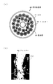
燃料濾過器60(自動逆洗濾器)は、図6(a)に示すように、中央部に集油管63(集合管)を備える円筒状の本体61内に、混合液体を外周面から取り込んで濾過材で濾過する24本の円筒状のフィルター62を設けたものである。
ここで、24本のフィルター62は、集油管63を二重に取り巻くように、内側に8本および外側に18本ほど配設されている。
ここで、24本のフィルター62は、集油管63を二重に取り巻くように、内側に8本および外側に18本ほど配設されている。
エマルジョン製造装置110を用いたエマルジョン燃料製造過程においては、燃料油や添加水にカビ菌(土壌菌)が含まれているとカビの発生が促進されるとともに、燃料油と添加水との混合物に熱が加わればカビが容易に発生する。
燃料油としてA重油を用いた場合には、A重油を強制的に加温する必要はないが、ディーゼルエンジン120からの燃料戻り油がリターンチャンバー130を介してエマルジョン製造装置110に戻される循環回路が形成されているため、ディーゼルエンジン120からの放熱によってA重油が若干加温された状態になる結果、エマルジョン燃料中にカビが発生し易い。
また、一般的にB重油は70℃以上強制的に加温するともにC重油は100℃以上に強制的に加温するため、燃料油としてB重油またはC重油を用いた場合には、A重油を用いた場合よりもカビが発生し易い。
また、一般的にB重油は70℃以上強制的に加温するともにC重油は100℃以上に強制的に加温するため、燃料油としてB重油またはC重油を用いた場合には、A重油を用いた場合よりもカビが発生し易い。
エマルジョン燃料中に発生したカビは、微細に混じり合った燃料油と添加水との境界面において燃料油を養分として繁殖する。
また、エマルジョン燃料によっては、エマルジョン燃料同士が結合して大きな結合体(スカム)となって粘性を増して燃料油配管13、添加水配管24およびエマルジョン燃料配管41の内壁や燃料濾過器60の各フィルター62の外周面に付着するため、付着した結合体にカビが発生して繁殖する。
また、エマルジョン燃料によっては、エマルジョン燃料同士が結合して大きな結合体(スカム)となって粘性を増して燃料油配管13、添加水配管24およびエマルジョン燃料配管41の内壁や燃料濾過器60の各フィルター62の外周面に付着するため、付着した結合体にカビが発生して繁殖する。
なお、下記の特許文献2には、被処理流体照射用のコイル部と、コイル部に周波数が時間的に変化する方形波の交流電流を流す還元(-)型変調電磁場発生器と、コイル部に周波数が時間的に変化する方形波にサイン波を乗せた交流電流を間欠的に流す酸化(+)型変調電磁場発生器と、これらの2つの変調電磁場発生器とコイル部との間にこれらの2つの変調電磁場発生器のいずれかを作動させるための切替器とを備えた変調電磁場処理装置が開示されている。
また、このような変調電磁場処理装置として、エスケーエイ株式会社製のウォーターウォッチャー(登録商標)が製品化されている。
また、このような変調電磁場処理装置として、エスケーエイ株式会社製のウォーターウォッチャー(登録商標)が製品化されている。
しかしながら、従来のエマルジョン燃料製造装置110では、エマルジョン燃料中に発生したカビが各フィルター62の外周面に付着すると燃料濾過器60の目詰まり(各フィルター62の目詰まり)が生じるため(図6(b)参照)、エマルジョン燃料に防カビ剤(薬品)を添加して、カビの生育を抑制したり既に発生したカビに対して菌糸の発育を阻害して死滅させたりしているが、防カビ剤以外による解決策が要請されている。
また、上記の特許文献2に開示された変調電磁場処理装置は、酸化(+)型変調電磁場発生器と還元(-)型変調電磁場発生器とを併用して、これらを切り替えてコイル部で変調電磁場を発生させる装置による電磁場処理により、あらゆる被処理流体(被処理水)を用いる流路または貯留槽の壁面でのスケールの付着防止および除去、あらゆる流路または貯留槽の壁面の腐食防止、油含有排水の流路の詰まり防止、アンモニア含有水からのアンモニア臭の脱臭、被処理水の濾過用フィルターの目詰まり防止、被処理水流路または貯留槽の壁面への海生物付着防止などの効果が得られることは分かっているが(公報の段落0049参照)、エマルジョン燃料中に発生したカビによる燃料濾過器の目詰まり防止にも有効であるか否かは不明であるという問題があった。
本発明の目的は、防カビ剤を用いずにカビによる燃料濾過器の目詰まりを防止することができるエマルジョン燃料製造装置および方法を提供することにある。
本発明のエマルジョン燃料製造装置は、カビ菌を含む燃料油とカビ菌を含む添加水と添加乳化剤とを混合および攪拌してエマルジョン燃料を製造するためのエマルジョン燃料製造装置(1)であって、燃料油配管(13)を介して供給される前記燃料油と添加水配管(24)を介して供給される前記添加水と添加乳化剤配管(34)を介して供給される前記添加乳化剤との混合液体を攪拌して前記エマルジョン燃料を生成するためのエマルジョン化装置(50)と、前記エマルジョン化装置で生成された前記エマルジョン燃料を濾過するための燃料濾過器(60)と、高周波のプラス型変調電磁場を発生するための酸化型変調電磁場発生装置(2)とを具備し、前記燃料油配管および前記添加水配管に前記酸化型変調電磁場発生装置から高周波のプラス型変調電磁場を印加して、前記カビ菌によって前記エマルジョン燃料中に発生するカビによる前記燃料濾過器の目詰まりを防止することを特徴とする。
ここで、前記酸化型変調電磁場発生装置が、燃料油配管コイル(2a)および添加水配管コイル(2b)を備え、前記燃料油配管コイルが、前記燃料油配管に巻き付けられており、前記添加水配管コイルが、前記添加水配管に巻き付けられており、前記酸化型変調電磁場発生装置が、高周波の方形波にサイン波を乗せた変調電磁場信号を前記燃料油配管コイルおよび前記添加水配管コイルに流して、前記高周波のプラス型変調電磁場を前記燃料油配管および前記添加水配管に印加してもよい。
前記酸化型変調電磁場発生装置が、前記燃料油配管コイルおよび前記添加水配管コイルの代わりにエマルジョン燃料配管コイルを備え、前記エマルジョン燃料配管コイルが、前記燃料油、前記添加水および前記添加乳化剤の混合液体を前記エマルジョン化装置に供給するためのエマルジョン燃料配管(41)に巻き付けられており、前記酸化型変調電磁場発生装置が、前記変調電磁場信号を前記エマルジョン燃料配管コイルに流して、前記高周波のプラス型変調電磁場を前記エマルジョン燃料配管に印加してもよい。
前記エマルジョン燃料配管に、外部から流入される前記エマルジョン燃料の戻り燃料油を前記エマルジョン化装置に供給するための戻り油配管(71)が接続されており、前記エマルジョン燃料配管コイルが、前記エマルジョン燃料配管の前記戻り油配管との接続点よりも下流側に巻き付けられていてもよい。
前記燃料油が、A重油であり、前記酸化型変調電磁場発生装置が、4万Hzのプラス型変調電磁場を発生してもよい。
前記酸化型変調電磁場発生装置が、ウォーターウォッチャー(登録商標)が備える酸化(+)型変調電磁場発生器であってもよい。
本発明のエマルジョン燃料製造方法は、カビ菌を含む燃料油とカビ菌を含む添加水と添加乳化剤とを混合および攪拌してエマルジョン燃料を製造するためのエマルジョン燃料製造方法であって、燃料油配管(13)を介して供給される前記燃料油と添加水配管(24)を介して供給される前記添加水と添加乳化剤配管(34)を介して供給される前記添加乳化剤とを混合して混合液体を生成する第1の製造過程と、前記混合液体をエマルジョン化装置(50)で攪拌して前記エマルジョン燃料を生成する第2の製造過程と、前記エマルジョン化装置で生成された前記エマルジョン燃料を燃料濾過器(60)で濾過する第3の製造過程とを具備し、酸化型変調電磁場発生装置(2)から前記燃料油配管および前記添加水配管に高周波のプラス型変調電磁場を印加して、前記カビ菌によって前記エマルジョン燃料中に発生するカビによる前記燃料濾過器の目詰まりを防止することを特徴とする。
ここで、前記酸化型変調電磁場発生装置が、燃料油配管コイル(2a)および添加水配管コイル(2b)を備え、前記燃料油配管コイルが、前記燃料油配管に巻き付けられており、前記添加水配管コイルが、前記添加水配管に巻き付けられており、前記酸化型変調電磁場発生装置が、高周波の方形波にサイン波を乗せた変調電磁場信号を前記燃料油配管コイルおよび前記添加水配管コイルに流して、前記高周波のプラス型変調電磁場を前記燃料油配管および前記添加水配管に印加してもよい。
前記酸化型変調電磁場発生装置が、前記燃料油配管コイルおよび前記添加水配管コイルの代わりにエマルジョン燃料配管コイルを備え、前記エマルジョン燃料配管コイルが、前記燃料油、前記添加水および前記添加乳化剤の混合液体を前記エマルジョン化装置に供給するためのエマルジョン燃料配管(41)に巻き付けられており、前記変調電磁場信号を前記酸化型変調電磁場発生装置から前記エマルジョン燃料配管コイルに流して、前記高周波のプラス型変調電磁場を前記エマルジョン燃料配管に印加してもよい。
前記エマルジョン燃料配管に、外部から流入される前記エマルジョン燃料の戻り燃料油を前記エマルジョン化装置に供給するための戻り油配管(71)が接続されており、前記エマルジョン燃料配管コイルが、前記エマルジョン燃料配管の前記戻り油配管との接続点よりも前記エマルジョン化装置側に巻き付けられていてもよい。
前記燃料油が、A重油であり、前記酸化型変調電磁場発生装置が、4万Hzのプラス型変調電磁場を発生してもよい。
前記酸化型変調電磁場発生装置が、ウォーターウォッチャー(登録商標)が備える酸化(+)型変調電磁場発生器であってもよい。
ここで、前記酸化型変調電磁場発生装置が、燃料油配管コイル(2a)および添加水配管コイル(2b)を備え、前記燃料油配管コイルが、前記燃料油配管に巻き付けられており、前記添加水配管コイルが、前記添加水配管に巻き付けられており、前記酸化型変調電磁場発生装置が、高周波の方形波にサイン波を乗せた変調電磁場信号を前記燃料油配管コイルおよび前記添加水配管コイルに流して、前記高周波のプラス型変調電磁場を前記燃料油配管および前記添加水配管に印加してもよい。
前記酸化型変調電磁場発生装置が、前記燃料油配管コイルおよび前記添加水配管コイルの代わりにエマルジョン燃料配管コイルを備え、前記エマルジョン燃料配管コイルが、前記燃料油、前記添加水および前記添加乳化剤の混合液体を前記エマルジョン化装置に供給するためのエマルジョン燃料配管(41)に巻き付けられており、前記酸化型変調電磁場発生装置が、前記変調電磁場信号を前記エマルジョン燃料配管コイルに流して、前記高周波のプラス型変調電磁場を前記エマルジョン燃料配管に印加してもよい。
前記エマルジョン燃料配管に、外部から流入される前記エマルジョン燃料の戻り燃料油を前記エマルジョン化装置に供給するための戻り油配管(71)が接続されており、前記エマルジョン燃料配管コイルが、前記エマルジョン燃料配管の前記戻り油配管との接続点よりも下流側に巻き付けられていてもよい。
前記燃料油が、A重油であり、前記酸化型変調電磁場発生装置が、4万Hzのプラス型変調電磁場を発生してもよい。
前記酸化型変調電磁場発生装置が、ウォーターウォッチャー(登録商標)が備える酸化(+)型変調電磁場発生器であってもよい。
本発明のエマルジョン燃料製造方法は、カビ菌を含む燃料油とカビ菌を含む添加水と添加乳化剤とを混合および攪拌してエマルジョン燃料を製造するためのエマルジョン燃料製造方法であって、燃料油配管(13)を介して供給される前記燃料油と添加水配管(24)を介して供給される前記添加水と添加乳化剤配管(34)を介して供給される前記添加乳化剤とを混合して混合液体を生成する第1の製造過程と、前記混合液体をエマルジョン化装置(50)で攪拌して前記エマルジョン燃料を生成する第2の製造過程と、前記エマルジョン化装置で生成された前記エマルジョン燃料を燃料濾過器(60)で濾過する第3の製造過程とを具備し、酸化型変調電磁場発生装置(2)から前記燃料油配管および前記添加水配管に高周波のプラス型変調電磁場を印加して、前記カビ菌によって前記エマルジョン燃料中に発生するカビによる前記燃料濾過器の目詰まりを防止することを特徴とする。
ここで、前記酸化型変調電磁場発生装置が、燃料油配管コイル(2a)および添加水配管コイル(2b)を備え、前記燃料油配管コイルが、前記燃料油配管に巻き付けられており、前記添加水配管コイルが、前記添加水配管に巻き付けられており、前記酸化型変調電磁場発生装置が、高周波の方形波にサイン波を乗せた変調電磁場信号を前記燃料油配管コイルおよび前記添加水配管コイルに流して、前記高周波のプラス型変調電磁場を前記燃料油配管および前記添加水配管に印加してもよい。
前記酸化型変調電磁場発生装置が、前記燃料油配管コイルおよび前記添加水配管コイルの代わりにエマルジョン燃料配管コイルを備え、前記エマルジョン燃料配管コイルが、前記燃料油、前記添加水および前記添加乳化剤の混合液体を前記エマルジョン化装置に供給するためのエマルジョン燃料配管(41)に巻き付けられており、前記変調電磁場信号を前記酸化型変調電磁場発生装置から前記エマルジョン燃料配管コイルに流して、前記高周波のプラス型変調電磁場を前記エマルジョン燃料配管に印加してもよい。
前記エマルジョン燃料配管に、外部から流入される前記エマルジョン燃料の戻り燃料油を前記エマルジョン化装置に供給するための戻り油配管(71)が接続されており、前記エマルジョン燃料配管コイルが、前記エマルジョン燃料配管の前記戻り油配管との接続点よりも前記エマルジョン化装置側に巻き付けられていてもよい。
前記燃料油が、A重油であり、前記酸化型変調電磁場発生装置が、4万Hzのプラス型変調電磁場を発生してもよい。
前記酸化型変調電磁場発生装置が、ウォーターウォッチャー(登録商標)が備える酸化(+)型変調電磁場発生器であってもよい。
本発明のエマルジョン燃料製造装置および方法は、以下に示す効果を奏する。
(1)防カビ剤を用いずにカビによる燃料濾過器の目詰まりを防止することができる。
(2)カビによる燃料濾過器のトラブルをなくせるため、設備信頼度の向上を図ることができるとともに、供給信頼度の向上も図ることができる。
(3)燃料濾過器の清掃作業をなくしたり、防カビ剤を添加する必要をなくしたりできるため、コストの低減を図ることができる。
(1)防カビ剤を用いずにカビによる燃料濾過器の目詰まりを防止することができる。
(2)カビによる燃料濾過器のトラブルをなくせるため、設備信頼度の向上を図ることができるとともに、供給信頼度の向上も図ることができる。
(3)燃料濾過器の清掃作業をなくしたり、防カビ剤を添加する必要をなくしたりできるため、コストの低減を図ることができる。
上記の目的を、燃料油配管および添加水配管に酸化型変調電磁場発生装置から高周波のプラス型変調電磁場を印加することにより実現した。
以下、本発明のエマルジョン燃料製造装置および方法の実施例について図面を参照して説明する。
本発明の一実施例によるエマルジョン燃料製造装置1は、図1に示すように、燃料油配管コイル2aおよび添加水配管コイル2bを備えた酸化型変調電磁場発生装置2を具備し、燃料油配管コイル2aを燃料油配管13の流量計12よりも下流側部分(混合液体供給ポンプ40側部分)に巻き付けるとともに、添加水配管コイル2bを添加水配管24の下流側部分(混合液体供給ポンプ40側部分)に巻き付けている点で、図5に示した従来のエマルジョン燃料製造装置110と異なる。
本発明の一実施例によるエマルジョン燃料製造装置1は、図1に示すように、燃料油配管コイル2aおよび添加水配管コイル2bを備えた酸化型変調電磁場発生装置2を具備し、燃料油配管コイル2aを燃料油配管13の流量計12よりも下流側部分(混合液体供給ポンプ40側部分)に巻き付けるとともに、添加水配管コイル2bを添加水配管24の下流側部分(混合液体供給ポンプ40側部分)に巻き付けている点で、図5に示した従来のエマルジョン燃料製造装置110と異なる。
ここで、酸化型変調電磁場発生装置2は、高周波(たとえば、4万Hz)の方形波にサイン波を乗せた変調電磁場信号を連続的または間欠的に燃料油配管コイル2aおよび添加水配管コイル2bに流して、高周波の変調電磁場(以下、「プラス型変調電磁場」と称する。)を燃料油配管13および添加水配管24に連続的または間欠的に印加するためのものであり、ウォーターウォッチャーが備える酸化(+)型変調電磁場発生器と同様の構成を有する(たとえば、発信器(OSC)からの信号を任意の周波数の信号に変換するための分周器と、分周器の出力信号が入力されて変調電磁場信号を生成するためのゼネレータと、ゼネレータの出力信号の電力を増幅するための電力増幅器とを備える。)。
したがって、酸化型変調電磁場発生装置2として、ウォーターウォッチャーが備える酸化(+)型変調電磁場発生器を用いることができる。
燃料油配管コイル2aと添加水配管コイル2bとは直列接続されている。
したがって、酸化型変調電磁場発生装置2として、ウォーターウォッチャーが備える酸化(+)型変調電磁場発生器を用いることができる。
燃料油配管コイル2aと添加水配管コイル2bとは直列接続されている。
エマルジョン燃料製造装置1では、燃料油供給装置11からの燃料油は、注水タンク21からの添加水、乳化剤タンク31からの添加乳化剤およびディーゼルエンジン120からリターンチャンバー130を介して戻ってくる燃料戻り油と混合され、エマルジョン化装置50でエマルジョン燃料にされたのち、燃料濾過器60を介してディーゼルエンジン120に供給される。
このとき、燃料油配管13および添加水配管24には、酸化型変調電磁場発生装置2から燃料油配管コイル2aおよび添加水配管コイル2bを介してプラス型変調電磁場が印加される。
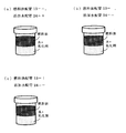
次に、本実施例によるエマルジョン燃料製造装置1を用いることにより燃料濾過器60の目詰まりを防止できることを確かめた実験結果について、図2(a),(b)および図3(a)~(h)を参照して説明する。
なお、酸化型変調電磁場発生装置2としてウォーターウォッチャーが備える酸化(+)型変調電磁場発生器を用いて、4万Hzのプラス型変調電磁場を燃料油配管13および添加水配管24に連続的に印加した。
また、燃料油としてA重油を用い、燃料濾過器60とディーゼルエンジン120とを接続するエマルジョン燃料配管41の途中からエマルジョン燃料をプラス型変調電磁場印加直後から15分毎にサンプリングして乳化状態を確認した。
さらに、通常時には水添加率=20%とするとともに燃料油と添加水とが良く混ざるように乳化剤添加率=2%としているが、この場合にはA重油と添加水と添加乳化剤との混合液体は白濁色となり、時間が経っても分離せずに安定しているため(図2(a)参照)、乳化剤添加率=1%としてサンプリング直後からA重油が添加水および添加乳化剤と分離するようにした(図2(b)参照)。
なお、酸化型変調電磁場発生装置2としてウォーターウォッチャーが備える酸化(+)型変調電磁場発生器を用いて、4万Hzのプラス型変調電磁場を燃料油配管13および添加水配管24に連続的に印加した。
また、燃料油としてA重油を用い、燃料濾過器60とディーゼルエンジン120とを接続するエマルジョン燃料配管41の途中からエマルジョン燃料をプラス型変調電磁場印加直後から15分毎にサンプリングして乳化状態を確認した。
さらに、通常時には水添加率=20%とするとともに燃料油と添加水とが良く混ざるように乳化剤添加率=2%としているが、この場合にはA重油と添加水と添加乳化剤との混合液体は白濁色となり、時間が経っても分離せずに安定しているため(図2(a)参照)、乳化剤添加率=1%としてサンプリング直後からA重油が添加水および添加乳化剤と分離するようにした(図2(b)参照)。
4万Hzのプラス型変調電磁場の印加直後にサンプリングしたエマルジョン燃料では、図3(a)に示すようにA重油(燃料油)が添加水および添加乳化剤から分離した。
同様に、4万Hzのプラス型変調電磁場の印加から15分後、30分後および45分後にそれぞれサンプリングしたエマルジョン燃料でも、図3(b)~(d)に示すようにA重油(燃料油)が添加水および添加乳化剤から分離した。
同様に、4万Hzのプラス型変調電磁場の印加から15分後、30分後および45分後にそれぞれサンプリングしたエマルジョン燃料でも、図3(b)~(d)に示すようにA重油(燃料油)が添加水および添加乳化剤から分離した。
しかしながら、4万Hzのプラス型変調電磁場の印加から60分後、75分後および90分後にそれぞれサンプリングしたエマルジョン燃料では、図3(e)~(g)に示すようにA重油(燃料油)が添加水および添加乳化剤から分離せずに、色相が灰色に変化した。
この理由としては、燃料油配管13および添加水配管24への4万Hzのプラス型変調電磁場の印加により燃料油と添加水とがプラス電位に荷電させられて振動し、燃料油配管13、添加水配管24およびエマルジョン燃料配管41や燃料濾過器60の各フィルター62に付着したカビが剥離してエマルジョン燃料中に混入したためと、燃料油配管13およびエマルジョン燃料配管41の内壁や燃料濾過器60の各フィルター62への結合体(スカム)の付着を防止するとともにエマルジョン燃料同士の反発作用も働かせて結合体自体の成長を防止したためと思われる。
この理由としては、燃料油配管13および添加水配管24への4万Hzのプラス型変調電磁場の印加により燃料油と添加水とがプラス電位に荷電させられて振動し、燃料油配管13、添加水配管24およびエマルジョン燃料配管41や燃料濾過器60の各フィルター62に付着したカビが剥離してエマルジョン燃料中に混入したためと、燃料油配管13およびエマルジョン燃料配管41の内壁や燃料濾過器60の各フィルター62への結合体(スカム)の付着を防止するとともにエマルジョン燃料同士の反発作用も働かせて結合体自体の成長を防止したためと思われる。
4万Hzのプラス型変調電磁場の印加から105分後にサンプリングしたエマルジョン燃料では、図3(h)に示すようにA重油(燃料油)が添加水および添加乳化剤から分離した。
この理由としては、燃料油配管13、添加水配管24およびエマルジョン燃料配管41の内壁や燃料濾過器60のフィルター62に付着したカビがなくなって、エマルジョン燃料中へのカビの混入がなくなったためと思われる。
この理由としては、燃料油配管13、添加水配管24およびエマルジョン燃料配管41の内壁や燃料濾過器60のフィルター62に付着したカビがなくなって、エマルジョン燃料中へのカビの混入がなくなったためと思われる。
次に、酸化型変調電磁場発生装置2の代わりにウォーターウォッチャーを用いて燃料油配管13および添加水配管24に印加する変調電磁場の極性の組合せを変えたときの比較実験結果について、図4(a)~(c)を参照して説明する。
なお、この比較実験では、燃料油配管コイル2aおよび添加水配管コイル2bは、直列接続せずに、燃料油配管13および添加水配管24にそれぞれ取り付けた。
なお、この比較実験では、燃料油配管コイル2aおよび添加水配管コイル2bは、直列接続せずに、燃料油配管13および添加水配管24にそれぞれ取り付けた。
(比較実験1)
ウォーターウォッチャーが備える還元型(-)変調電磁場発生器に燃料油配管コイル2aを接続して4万Hzの変調電磁場(4万Hzを中心として周波数が時間的に変化する方形波の変調電磁場信号を連続的または間欠的にコイルに流して生成される変調電磁場。以下、「マイナス型変調電磁場」と称する。)を燃料油配管13に印加するとともに、ウォーターウォッチャーが備える酸化型(+)変調電磁場発生器に添加水配管コイル2bを接続して4万Hzのプラス型変調電磁場を添加水配管24に印加した場合には、印加直後から105分後までサンプリングしたエマルジョン燃料のすべてにおいて、A重油(燃料油)が添加水および添加乳化剤から分離した(図4(a)参照)。
ウォーターウォッチャーが備える還元型(-)変調電磁場発生器に燃料油配管コイル2aを接続して4万Hzの変調電磁場(4万Hzを中心として周波数が時間的に変化する方形波の変調電磁場信号を連続的または間欠的にコイルに流して生成される変調電磁場。以下、「マイナス型変調電磁場」と称する。)を燃料油配管13に印加するとともに、ウォーターウォッチャーが備える酸化型(+)変調電磁場発生器に添加水配管コイル2bを接続して4万Hzのプラス型変調電磁場を添加水配管24に印加した場合には、印加直後から105分後までサンプリングしたエマルジョン燃料のすべてにおいて、A重油(燃料油)が添加水および添加乳化剤から分離した(図4(a)参照)。
(比較実験2)
ウォーターウォッチャーが備える還元型(-)変調電磁場発生器に燃料油配管コイル2aおよび添加水配管コイル2bを接続して4万Hzのマイナス型変調電磁場を燃料油配管13および添加水配管24に印加した場合にも、印加直後から105分後までサンプリングしたエマルジョン燃料のすべてにおいて、A重油(燃料油)が添加水および添加乳化剤から分離した(図4(b)参照)。
ウォーターウォッチャーが備える還元型(-)変調電磁場発生器に燃料油配管コイル2aおよび添加水配管コイル2bを接続して4万Hzのマイナス型変調電磁場を燃料油配管13および添加水配管24に印加した場合にも、印加直後から105分後までサンプリングしたエマルジョン燃料のすべてにおいて、A重油(燃料油)が添加水および添加乳化剤から分離した(図4(b)参照)。
(比較実験3)
ウォーターウォッチャーが備える酸化型(+)変調電磁場発生器に燃料油配管コイル2aを接続して4万Hzのプラス型変調電磁場を燃料油配管13に印加するとともにウォーターウォッチャーが備える還元型(-)変調電磁場発生器に添加水配管コイル2bを接続して4万Hzのマイナス型変調電磁場を添加水配管コイル2bに印加した場合にも、印加直後から105分後までサンプリングしたエマルジョン燃料のすべてにおいて、A重油(燃料油)が添加水および添加乳化剤から分離した(図4(c)参照)。
ウォーターウォッチャーが備える酸化型(+)変調電磁場発生器に燃料油配管コイル2aを接続して4万Hzのプラス型変調電磁場を燃料油配管13に印加するとともにウォーターウォッチャーが備える還元型(-)変調電磁場発生器に添加水配管コイル2bを接続して4万Hzのマイナス型変調電磁場を添加水配管コイル2bに印加した場合にも、印加直後から105分後までサンプリングしたエマルジョン燃料のすべてにおいて、A重油(燃料油)が添加水および添加乳化剤から分離した(図4(c)参照)。
なお、以上の説明では、燃料油配管コイル2aおよび添加水配管コイル2bを備えた酸化型変調電磁場発生装置2を用いて燃料油配管13の流量計12よりも下流側に巻き付けるとともに添加水配管コイル2bを添加水配管24の下流側に巻き付けたが、燃料油配管コイル2aおよび添加水配管コイル2bの代わりに1つのエマルジョン燃料配管コイルを備えた酸化型変調電磁場発生装置(酸化型変調電磁場発生装置2と同様の構成のもの)を用いて、エマルジョン燃料配管コイルをエマルジョン燃料配管41の戻り油配管71との接続箇所よりも上流側(流量計12側)に取り付けて、この酸化型変調電磁場発生装置からエマルジョン燃料配管41にプラス型変調電磁場を印加しても、エマルジョン燃料配管41の内壁および燃料濾過器60に付着したカビを剥離することができるため、同様の効果が得られる。
同様に、この酸化型変調電磁場発生装置のエマルジョン燃料配管コイルをエマルジョン燃料配管41の戻り油配管71との接続箇所よりも下流側(混合液体供給ポンプ40側)に取り付けて、この酸化型変調電磁場発生装置からエマルジョン燃料配管41にプラス型変調電磁場を印加しても、エマルジョン燃料配管41の内壁および燃料濾過器60に付着したカビを剥離することができるため、同様の効果が得られる。
また、酸化型変調電磁場発生装置2から燃料油配管13および添加水配管24にプラス型変調電磁場を常時印加してもよいし、カビは一度除去すると燃料濾過器60の各フィルター62に付着して目詰まりを生じさせるのに時間を要するため、たとえばエマルジョン燃料製造装置1の定期点検時などにのみ酸化型変調電磁場発生装置2から燃料油配管13および添加水配管24にプラス型変調電磁場を印加するようにしてもよい。
1,110 エマルジョン燃料製造装置
2 酸化型変調電磁場発生装置
2a 燃料油配管コイル
2b 添加水配管コイル
11 燃料油供給装置
12 流量計
13 燃料油配管
20 注水タンクユニット
21 注水タンク
22 添加水供給ポンプ
23 添加水流量調整弁
24 添加水配管
30 乳化剤タンクユニット
31 乳化剤タンク
32 添加乳化剤供給ポンプ
33 添加乳化剤流量調整弁
34 添加乳化剤配管
40 混合液体供給ポンプ
41 エマルジョン燃料配管
50 エマルジョン化装置
60 燃料濾過器
61 本体
62 フィルター
63 集油管
71 戻り油配管
120 ディーゼルエンジン
130 リターンチャンバー
2 酸化型変調電磁場発生装置
2a 燃料油配管コイル
2b 添加水配管コイル
11 燃料油供給装置
12 流量計
13 燃料油配管
20 注水タンクユニット
21 注水タンク
22 添加水供給ポンプ
23 添加水流量調整弁
24 添加水配管
30 乳化剤タンクユニット
31 乳化剤タンク
32 添加乳化剤供給ポンプ
33 添加乳化剤流量調整弁
34 添加乳化剤配管
40 混合液体供給ポンプ
41 エマルジョン燃料配管
50 エマルジョン化装置
60 燃料濾過器
61 本体
62 フィルター
63 集油管
71 戻り油配管
120 ディーゼルエンジン
130 リターンチャンバー
Claims (12)
- カビ菌を含む燃料油とカビ菌を含む添加水と添加乳化剤とを混合および攪拌してエマルジョン燃料を製造するためのエマルジョン燃料製造装置(1)であって、
燃料油配管(13)を介して供給される前記燃料油と添加水配管(24)を介して供給される前記添加水と添加乳化剤配管(34)を介して供給される前記添加乳化剤との混合液体を攪拌して前記エマルジョン燃料を生成するためのエマルジョン化装置(50)と、
前記エマルジョン化装置で生成された前記エマルジョン燃料を濾過するための燃料濾過器(60)と、
高周波のプラス型変調電磁場を発生するための酸化型変調電磁場発生装置(2)とを具備し、
前記燃料油配管および前記添加水配管に前記酸化型変調電磁場発生装置から高周波のプラス型変調電磁場を印加して、前記カビ菌によって前記エマルジョン燃料中に発生するカビによる前記燃料濾過器の目詰まりを防止する、
ことを特徴とする、エマルジョン燃料製造装置。 - 前記酸化型変調電磁場発生装置が、燃料油配管コイル(2a)および添加水配管コイル(2b)を備え、
前記燃料油配管コイルが、前記燃料油配管に巻き付けられており、
前記添加水配管コイルが、前記添加水配管に巻き付けられており、
前記酸化型変調電磁場発生装置が、高周波の方形波にサイン波を乗せた変調電磁場信号を前記燃料油配管コイルおよび前記添加水配管コイルに流して、前記高周波のプラス型変調電磁場を前記燃料油配管および前記添加水配管に印加する、
ことを特徴とする、請求項1記載のエマルジョン燃料製造装置。 - 前記酸化型変調電磁場発生装置が、前記燃料油配管コイルおよび前記添加水配管コイルの代わりにエマルジョン燃料配管コイルを備え、
前記エマルジョン燃料配管コイルが、前記燃料油、前記添加水および前記添加乳化剤の混合液体を前記エマルジョン化装置に供給するためのエマルジョン燃料配管(41)に巻き付けられており、
前記酸化型変調電磁場発生装置が、前記変調電磁場信号を前記エマルジョン燃料配管コイルに流して、前記高周波のプラス型変調電磁場を前記エマルジョン燃料配管に印加する、
ことを特徴とする、請求項2記載のエマルジョン燃料製造装置。 - 前記エマルジョン燃料配管に、外部から流入される前記エマルジョン燃料の戻り燃料油を前記エマルジョン化装置に供給するための戻り油配管(71)が接続されており、
前記エマルジョン燃料配管コイルが、前記エマルジョン燃料配管の前記戻り油配管との接続点よりも前記エマルジョン化装置側に巻き付けられている、
ことを特徴とする、請求項3記載のエマルジョン燃料製造装置。 - 前記燃料油が、A重油であり、
前記酸化型変調電磁場発生装置が、4万Hzのプラス型変調電磁場を発生する、
ことを特徴とする、請求項1乃至4いずれかに記載のエマルジョン燃料製造装置。 - 前記酸化型変調電磁場発生装置が、ウォーターウォッチャー(登録商標)が備える酸化(+)型変調電磁場発生器であることを特徴とする、請求項1乃至5いずれかに記載のエマルジョン燃料製造装置。
- カビ菌を含む燃料油とカビ菌を含む添加水と添加乳化剤とを混合および攪拌してエマルジョン燃料を製造するためのエマルジョン燃料製造方法であって、
燃料油配管(13)を介して供給される前記燃料油と添加水配管(24)を介して供給される前記添加水と添加乳化剤配管(34)を介して供給される前記添加乳化剤とを混合して混合液体を生成する第1の製造過程と、
前記混合液体をエマルジョン化装置(50)で攪拌して前記エマルジョン燃料を生成する第2の製造過程と、
前記エマルジョン化装置で生成された前記エマルジョン燃料を燃料濾過器(60)で濾過する第3の製造過程とを具備し、
酸化型変調電磁場発生装置(2)から前記燃料油配管および前記添加水配管に高周波のプラス型変調電磁場を印加して、前記カビ菌によって前記エマルジョン燃料中に発生するカビによる前記燃料濾過器の目詰まりを防止する、
ことを特徴とする、エマルジョン燃料製造方法。 - 前記酸化型変調電磁場発生装置が、燃料油配管コイル(2a)および添加水配管コイル(2b)を備え、
前記燃料油配管コイルが、前記燃料油配管に巻き付けられており、
前記添加水配管コイルが、前記添加水配管に巻き付けられており、
前記酸化型変調電磁場発生装置が、高周波の方形波にサイン波を乗せた変調電磁場信号を前記燃料油配管コイルおよび前記添加水配管コイルに流して、前記高周波のプラス型変調電磁場を前記燃料油配管および前記添加水配管に印加する、
ことを特徴とする、請求項7記載のエマルジョン燃料製造方法。 - 前記酸化型変調電磁場発生装置が、前記燃料油配管コイルおよび前記添加水配管コイルの代わりにエマルジョン燃料配管コイルを備え、
前記エマルジョン燃料配管コイルが、前記燃料油、前記添加水および前記添加乳化剤の混合液体を前記エマルジョン化装置に供給するためのエマルジョン燃料配管(41)に巻き付けられており、
前記変調電磁場信号を前記酸化型変調電磁場発生装置から前記エマルジョン燃料配管コイルに流して、前記高周波のプラス型変調電磁場を前記エマルジョン燃料配管に印加する、
ことを特徴とする、請求項8記載のエマルジョン燃料製造方法。 - 前記エマルジョン燃料配管に、外部から流入される前記エマルジョン燃料の戻り燃料油を前記エマルジョン化装置に供給するための戻り油配管(71)が接続されており、
前記エマルジョン燃料配管コイルが、前記エマルジョン燃料配管の前記戻り油配管との接続点よりも前記エマルジョン化装置側に巻き付けられている、
ことを特徴とする、請求項9記載のエマルジョン燃料製造方法。 - 前記燃料油が、A重油であり、
前記酸化型変調電磁場発生装置が、4万Hzのプラス型変調電磁場を発生する、
ことを特徴とする、請求項1乃至10いずれかに記載のエマルジョン燃料製造方法。 - 前記酸化型変調電磁場発生装置が、ウォーターウォッチャー(登録商標)が備える酸化(+)型変調電磁場発生器であることを特徴とする、請求項7乃至11いずれかに記載のエマルジョン燃料製造方法。
Priority Applications (2)
| Application Number | Priority Date | Filing Date | Title |
|---|---|---|---|
| JP2016542793A JP6039865B1 (ja) | 2015-06-17 | 2015-06-17 | エマルジョン燃料製造装置および方法 |
| PCT/JP2015/067426 WO2016203564A1 (ja) | 2015-06-17 | 2015-06-17 | エマルジョン燃料製造装置および方法 |
Applications Claiming Priority (1)
| Application Number | Priority Date | Filing Date | Title |
|---|---|---|---|
| PCT/JP2015/067426 WO2016203564A1 (ja) | 2015-06-17 | 2015-06-17 | エマルジョン燃料製造装置および方法 |
Publications (1)
| Publication Number | Publication Date |
|---|---|
| WO2016203564A1 true WO2016203564A1 (ja) | 2016-12-22 |
Family
ID=57483143
Family Applications (1)
| Application Number | Title | Priority Date | Filing Date |
|---|---|---|---|
| PCT/JP2015/067426 Ceased WO2016203564A1 (ja) | 2015-06-17 | 2015-06-17 | エマルジョン燃料製造装置および方法 |
Country Status (2)
| Country | Link |
|---|---|
| JP (1) | JP6039865B1 (ja) |
| WO (1) | WO2016203564A1 (ja) |
Cited By (2)
| Publication number | Priority date | Publication date | Assignee | Title |
|---|---|---|---|---|
| CN111788379A (zh) * | 2018-03-19 | 2020-10-16 | 全耐塑料高级创新研究公司 | 将水溶液喷射到内燃机的燃烧室中的车辆系统和将水溶液喷射到内燃机的燃烧室中的方法 |
| WO2025154776A1 (ja) * | 2024-01-16 | 2025-07-24 | 裕行 澤山 | 着火改善剤 |
Families Citing this family (2)
| Publication number | Priority date | Publication date | Assignee | Title |
|---|---|---|---|---|
| KR102276599B1 (ko) * | 2020-01-28 | 2021-07-14 | (주)로우카본 | 황산화물 저감을 위한 연료유 및 탈황제의 에멀전화 방법 |
| KR102276604B1 (ko) * | 2020-01-28 | 2021-07-14 | (주)로우카본 | 항만용 연료유의 탈황제 혼합 시스템 |
Citations (3)
| Publication number | Priority date | Publication date | Assignee | Title |
|---|---|---|---|---|
| JP2000510547A (ja) * | 1997-04-18 | 2000-08-15 | ビョーンソン,アエガー | 燃料のような液状媒体のための供給および濾過システム |
| JP2011230110A (ja) * | 2010-04-26 | 2011-11-17 | Tadakazu Ichikawa | 濾過装置 |
| JP2014181302A (ja) * | 2013-03-19 | 2014-09-29 | Matsuo Junichi | マイクロエマルジョン生成装置 |
-
2015
- 2015-06-17 JP JP2016542793A patent/JP6039865B1/ja active Active
- 2015-06-17 WO PCT/JP2015/067426 patent/WO2016203564A1/ja not_active Ceased
Patent Citations (3)
| Publication number | Priority date | Publication date | Assignee | Title |
|---|---|---|---|---|
| JP2000510547A (ja) * | 1997-04-18 | 2000-08-15 | ビョーンソン,アエガー | 燃料のような液状媒体のための供給および濾過システム |
| JP2011230110A (ja) * | 2010-04-26 | 2011-11-17 | Tadakazu Ichikawa | 濾過装置 |
| JP2014181302A (ja) * | 2013-03-19 | 2014-09-29 | Matsuo Junichi | マイクロエマルジョン生成装置 |
Cited By (4)
| Publication number | Priority date | Publication date | Assignee | Title |
|---|---|---|---|---|
| CN111788379A (zh) * | 2018-03-19 | 2020-10-16 | 全耐塑料高级创新研究公司 | 将水溶液喷射到内燃机的燃烧室中的车辆系统和将水溶液喷射到内燃机的燃烧室中的方法 |
| CN111788379B (zh) * | 2018-03-19 | 2022-07-12 | 全耐塑料高级创新研究公司 | 将水溶液喷射到内燃机的燃烧室上游的进气管线中或喷射到内燃机的燃烧室中的车辆系统和方法 |
| US11623881B2 (en) | 2018-03-19 | 2023-04-11 | Plastic Omnium Advanced Innovation And Research | Vehicle system for injecting an aqueous solution in the combustion chamber of the internal combustion engine and method for injecting an aqueous solution in the combustion chamber of the internal combustion |
| WO2025154776A1 (ja) * | 2024-01-16 | 2025-07-24 | 裕行 澤山 | 着火改善剤 |
Also Published As
| Publication number | Publication date |
|---|---|
| JPWO2016203564A1 (ja) | 2017-06-29 |
| JP6039865B1 (ja) | 2016-12-07 |
Similar Documents
| Publication | Publication Date | Title |
|---|---|---|
| JP6039865B1 (ja) | エマルジョン燃料製造装置および方法 | |
| US10934197B2 (en) | Electronic water pre-treatment equipment and methods | |
| JP2015085297A (ja) | 液体処理装置および随伴水処理方法 | |
| US20210024387A1 (en) | Apparatus and method for oxidative treatment of organic contaminants in waste water | |
| JP2013515818A (ja) | 水性硫化水素スカベンジャーの効果を高めるための炭化水素ガスオイルの乳化 | |
| CN106673277B (zh) | 一种应用于油气田压裂返排液深度处理达标外排的方法 | |
| EP3737648A1 (en) | Wastewater treatment method | |
| Praly et al. | Further results on robust semiglobal stabilization with dynamic input uncertainties | |
| CN103880204A (zh) | 一种去除电镀废水中镍离子的方法 | |
| Mathivanan et al. | Enhanced photocatalytic decolorization of reactive red by sonocatalysis using TiO2 catalyst: factorial design of experiments | |
| KR101634667B1 (ko) | 전자기장을 이용한 고농도 오존수 생성 장치 | |
| WO2015037678A1 (ja) | 相溶性透明含水油の製造方法及び相溶性透明含水油製造装置 | |
| JP2002248339A (ja) | 水と油との混合物であるエマルジョン流体の製造方法およびエマルジョン流体およびエマルジョン流体の製造装置およびエマルジョン燃料の燃焼方法。 | |
| JP2009082813A (ja) | 水処理方法および水処理装置 | |
| DE102007043302A1 (de) | Vorrichtung zur Bildung von Emulsionen aus flüssigen Kraft- und Brennstoffen und Wasser, wässrigen Lösungen und anderen flüssigen Stoffen, zur besseren Verbrennung und Schadstoffreduzierung | |
| JP2006136771A (ja) | カルシウム含有水の処理方法と装置 | |
| JP2017087147A (ja) | 水処理方法 | |
| JP5619204B2 (ja) | マイクロエマルジョン生成装置 | |
| JPH0352692A (ja) | 廃水のフエントン処理方法 | |
| EP1676815A1 (fr) | Procédé de traitement électromagnétique des liquides | |
| EP3795543A1 (de) | Verfahren zur optimierung der entwässerung von mikroorganismen aufweisendem schlamm | |
| KR101673134B1 (ko) | 슬러지 감량장치 | |
| JP2022030987A (ja) | 被膜ろ過水の前処理装置および前処理方法、並びに、膜ろ過システムおよび膜ろ過方法 | |
| JP3161307U (ja) | 乳化促進水の生成装置 | |
| JP2009214011A (ja) | 水処理方法および水処理装置 |
Legal Events
| Date | Code | Title | Description |
|---|---|---|---|
| ENP | Entry into the national phase |
Ref document number: 2016542793 Country of ref document: JP Kind code of ref document: A |
|
| 121 | Ep: the epo has been informed by wipo that ep was designated in this application |
Ref document number: 15895585 Country of ref document: EP Kind code of ref document: A1 |
|
| NENP | Non-entry into the national phase |
Ref country code: DE |
|
| 122 | Ep: pct application non-entry in european phase |
Ref document number: 15895585 Country of ref document: EP Kind code of ref document: A1 |