WO2016203535A1 - 内視鏡 - Google Patents
内視鏡 Download PDFInfo
- Publication number
- WO2016203535A1 WO2016203535A1 PCT/JP2015/067252 JP2015067252W WO2016203535A1 WO 2016203535 A1 WO2016203535 A1 WO 2016203535A1 JP 2015067252 W JP2015067252 W JP 2015067252W WO 2016203535 A1 WO2016203535 A1 WO 2016203535A1
- Authority
- WO
- WIPO (PCT)
- Prior art keywords
- endoscope
- disposed
- wiring board
- heat
- extending
- Prior art date
- Legal status (The legal status is an assumption and is not a legal conclusion. Google has not performed a legal analysis and makes no representation as to the accuracy of the status listed.)
- Ceased
Links
Images




Classifications
-
- A—HUMAN NECESSITIES
- A61—MEDICAL OR VETERINARY SCIENCE; HYGIENE
- A61B—DIAGNOSIS; SURGERY; IDENTIFICATION
- A61B1/00—Instruments for performing medical examinations of the interior of cavities or tubes of the body by visual or photographical inspection, e.g. endoscopes; Illuminating arrangements therefor
- A61B1/04—Instruments for performing medical examinations of the interior of cavities or tubes of the body by visual or photographical inspection, e.g. endoscopes; Illuminating arrangements therefor combined with photographic or television appliances
Definitions
- the present invention is an endoscope having a cylinder at the tip end of the insertion portion, and an imaging element, a wiring board on which a heat generating component is disposed, and a tubular member are provided inside the cylinder. About.
- Endoscopes are widely used in the medical and industrial fields.
- the subject is imaged by an imaging device disposed at the tip of the insertion portion of the endoscope, and the subject image is displayed on the monitor of the apparatus main body.
- active components such as integrated circuit components that supply drive signals to the imaging device are also disposed.
- the active component is a heat generating component that generates heat when performing a predetermined operation with the received power.
- the heat generated by the heat generating component is transferred to the imaging device and the temperature of the imaging device rises, the imaging device may be degraded or the image quality may be degraded due to thermal noise.
- Japanese Patent Application Laid-Open No. 2013-233343 discloses an endoscope in which the back surface of an imaging element is closely fixed to the outer surface of a forceps pipe with an adhesive in order to dissipate heat generated by the imaging element as a heating element. .
- the heating element is disposed at the tip end portion in addition to the imaging element, the imaging element serves as a heat radiation path of the heat generated by the heating element, and the temperature may increase. there were.
- An object of the present invention is to provide an endoscope in which the heat generated by the heat generating component may not adversely affect the imaging device.
- the endoscope according to the embodiment of the present invention has a cylindrical body at the distal end portion of the insertion portion, and the imaging device, the flexible wiring board, and the distal end portion are inserted inside the cylindrical body.
- An endoscope provided with a tubular member, the wiring board including an intermediate portion connected to the imaging device and an extending portion extending from a side of the intermediate portion; The extended portion in which the heat generating component is disposed is in contact with the tubular member.
- the endoscope system 1 includes an endoscope 2, a processor 5A, a light source device 5B, and a monitor 5C.
- the endoscope 2 captures an in-vivo image of the subject by inserting the elongated insertion portion 3 into a body cavity of the subject, and outputs an imaging signal.
- the operation unit 4 has a treatment tool insertion port 4A of a forceps tube (channel) 22 (see FIG. 2) for inserting treatment tools such as a biological forceps, an electric knife and a test probe into a body cavity of a subject.
- the insertion portion 3 includes a distal end portion 3A in which the imaging element 50 is disposed, a bendable curved portion 3B continuously provided on the proximal end side of the distal end portion 3A, and a continuous end provided on the proximal end side of the curved portion 3B. And the flexible tube portion 3C.
- the bending portion 3B is bent by the operation of the operation unit 4.
- the endoscope 2 may be a so-called flexible endoscope, but may be a so-called rigid endoscope in which the insertion portion 3 is rigid.
- a signal cable 61 connected to the imaging device 50 of the distal end 3A is inserted into the universal cord 4B disposed on the proximal end side of the operation unit 4.
- the universal cord 4B is connected to the processor 5A and the light source device 5B via the connector 4C.
- the processor 5A controls the entire endoscope system 1, performs signal processing on an imaging signal output from the imaging element 50, and outputs an image signal.
- the monitor 5C displays an image signal output by the processor 5A.
- the light source device 5B includes, for example, a white LED.
- the light emitted from the light source device 5B is guided to the distal end portion 3A through the universal cord 4B and the light guides 24 and 25 (see FIG. 3) inserted through the insertion portion 3 to illuminate the subject.
- the endoscope 2 has a cylindrical body 20 at the distal end portion 3A of the insertion portion 3, and an imaging element 50 and a flexible wiring board 30 inside the cylindrical body 20. And a suction pipe 21 and a forceps pipe 22 which are tubular members through which the distal end portion 3A is inserted.
- a suction pipe 21 and a forceps pipe 22 which are tubular members through which the distal end portion 3A is inserted.
- FIG. 2 only the suction pipe 21 and the forceps pipe 22 are shown among the components arrange
- the outer surface of the cylindrical body 20 is covered with a shell resin layer (not shown).
- a sealing resin 26 is selected from resins excellent in moisture resistance, such as epoxy resin or silicone resin.
- An illumination optical system 24 T emits the illumination light guided by the opening 21 H of the suction tube 21, the opening 22 H of the forceps tube 22, the opening 23 T of the water supply / traffic tube 23, and the light guides 24 and 25 on the tip surface of the insertion portion 3. , 25T, and the tip surface of the objective optical system 52 for forming an object image on the imaging device 50.
- the suction pipe 21 and the water supply / air supply pipe 23 pass through the insertion portion 3 and the universal cord 4B and are connected to a suction pump and a water supply / air supply pump (not shown). That is, the suction pipe 21, the forceps pipe 22, and the water supply / air supply pipe 23 have an opening at the tip end surface through which the tip end portion 3A is inserted.
- Wiring board 30 includes middle portion 31 including tip region 31A, and extension portions 32 and 33 extending from both sides of middle portion 31, respectively.
- a chip capacitor 49 is disposed in the middle portion 31, an imaging device 30 is disposed in the distal end region 31 A, a drive IC 41 is disposed in the extension portion 32, and a drive IC 42 is disposed in the extension portion 33.
- the main surface of middle part 31 of wiring board 30 in the middle of manufacture before being inserted in cylindrical body 20 of tip 3A and the main surfaces of extended parts 32 and 33 are the same planes It is above.
- the front end region 31A of the middle portion 31 of the wiring board 30 is bent, and the cover glass 53 is bonded to the back surface of the imaging device 50 disposed on the light receiving surface.
- the imaging device 50 is a substantially rectangular chip on which a light receiving unit 51 such as a CCD or a CMOS sensor is formed. Note that the imaging device 50 may be a backside illumination type.
- An objective optical system 52 including a plurality of lenses is disposed on the light receiving surface of the imaging device 50 via a cover glass 53.
- the wiring board 30 has a substantially cross shape including the middle portion 31 and the extending portions 32 and 33 extending from the side of the middle portion 31.
- the wiring board 30 may be a single-sided wiring board, a multilayer wiring board, or an electronic component built-in wiring board.
- the flexible wiring board 30 uses, for example, a polyimide as a base, and a wiring pattern made of, for example, copper is disposed on both sides.
- the front end region 31A is bonded to the back surface of the imaging element 50, and the cable 61 is connected to the rear end region.
- the main surface of the tip region 31A of the middle portion 31 of the wiring board 30 is bent 90 degrees with respect to the main surface of the middle portion 31. Then, although not shown, an external electrode disposed on the back surface of the imaging device 50 and a tip electrode of the wiring board 30 are joined.
- the electrical connection between the imaging element 50 and the wiring board 30 is not limited to the above configuration, and for example, a flying lead protruding from the tip end face of the wiring board 30 is joined to the external electrode of the light receiving surface of the imaging element 50 May be If the flying leads are bent 90 degrees, the end region 31A of the wiring board 30 may not be bent with respect to the middle portion 31.
- the main surface of the extending portion 32 is bent with respect to the main surface (the first main surface 30SA and the second main surface 30SB) of the middle portion 31 and the bending angle ⁇ 1 (see FIG. 5) is a suction pipe 21 is defined by contact.
- the main surface of the extended portion 33 is also bent with respect to the main surface of the intermediate portion 31, and the bending angle ⁇ 2 (see FIG. 5) is defined by contact with the insulator tube 22.
- the wiring board 30 is provided with a plurality of electronic components.
- the electronic component 49 with a small amount of heat generation for example, a chip capacitor which is a passive component, is disposed on the first main surface 30SA of the middle portion 31 of the wiring board 30, while the drive ICs 41 and 42 which are active components. Are disposed on the second main surface 30SB of the extension portions 32 and 33.
- the driving IC is an integrated circuit (Integrated Circuit) component sometimes called a peripheral IC.
- the arrangement position of the drive ICs 41 and 42 is far from the arrangement position of the imaging device 50, since the extension portions 32 and 33 are bent, the diameter and the length of the tip portion 3A are small.
- the drive IC 41 is a high heat generation component having the largest amount of heat generation at the time of driving among the plurality of electronic components disposed on the wiring board 30.
- the drive IC 42 is a heat generation component having the same amount of heat generation as the drive IC 41 or a large amount of heat generation next to the drive IC 41.
- the drive ICs 41 and 42 which are heat-generating components, are disposed in the extension portions 32 and 33 so as to be apart from the distal end region 31A in which the imaging element 50 is disposed.
- the first main surface 30SA of the extending portion 32 is in contact with the outer surface of the suction pipe 21, and the first main surface 30SA of the extending portion 32 is with the outer surface of the insulator tube 22. It abuts.
- the suction tube 21 and the insulator tube 22 are preferably made of a material having high thermal conductivity, such as metal. However, since the suction pipe 21 and the like pass through the tip end portion 3A and have an opening on the tip end surface, the air cooling effect ensures good heat dissipation efficiency even if the material has a relatively low thermal conductivity, for example, a resin material such as PTFE. .
- the wiring board 30 is inserted into the inside of the cylindrical body 20 in which the suction pipe 21 and the insulator pipe 22 have already been inserted while bending the extending portions 32 and 33.
- the signal cable 61 and the like are not shown.
- the extending portions 32 and 33 are urged by the repulsive force of the bent portion of the wiring board 30 and abut on the suction pipe 21 and the insulator pipe 22.
- the bending angles ⁇ 1 and ⁇ 2 with respect to the main surface of the intermediate portion 31 of the main surfaces of the extending portions 32 and 33 are defined by abutting on the tubular members (the suction pipe 21 and the forceps pipe 22).
- the flexible extending portions 32, 33 are biased, they are not in line contact but in surface contact when in contact with the tubular member.
- the extended portions 32 and 33 in surface contact with the tubular member have a large heat transfer area, so that the heat dissipation efficiency is good.
- the heat generated by the drive ICs 41 and 42 as heat generating components is dissipated through the suction pipe 21 and the forceps pipe 22. That is, the imaging device 50 is not located in the heat transfer path of the heat generated by the heat generating component.
- the heat generated by the drive ICs 41 and 42 is transferred through the contact portion with the suction pipe 21 and the insulator pipe 22.
- the heat generated by the drive ICs 41 and 42 is hardly transferred to the imaging device 50, and therefore, there is no risk of adversely affecting the imaging device 50.
- At least one of the length, the shape, or the bending angle may be different between the extending portion 32 and the extending portion 33 extended from the side surface of the middle portion 31 of the wiring board 30.
- the wiring board 30 is a single flexible wiring board, the boundary between the intermediate portion 31 and the extending portions 32 and 33 is not clearly defined.
- the extension portion 33 is unnecessary. That is, the extending portions do not need to be extended from both side surfaces of the intermediate portion 31, respectively.
- the wiring board may include at least one extension.
- each extending portion may be in contact with any one of the tubular members through which the distal end portion 3A is inserted.
- a plurality of extension parts may be in contact with one tubular member.
- the wiring board 30 preferably has a heat transfer pattern along the heat transfer path of the heat-generating component, in addition to the wiring pattern for electrical connection. That is, the wiring board 30 does not contribute to the electrical connection.
- the heat transfer pattern of the ground potential be disposed around the wiring pattern.
- the heat transfer pattern is made of a high thermal conductivity material such as copper or gold which is the same as the wiring pattern.
- the copper film is removed only in a frame shape along the outer periphery of the wiring pattern, leaving its periphery
- a heat transfer pattern can be formed.
- An endoscope having a wiring board with a heat transfer pattern from the heat transfer path of the heat generating component, ie, the portion where the heat generating component is disposed to the portion in contact with the tubular member, makes the heat generated by the heat generating component more efficient.
- the heat can be transferred to the tubular member.
- the heat transfer pattern is formed Preferably not.
- an endoscope 2A of a modification of the first embodiment will be described. Since the endoscope 2A is similar to the endoscope 2, the components having the same functions are denoted by the same reference numerals and the description thereof will be omitted.
- the endoscope 2A has a light emitting element 41A which is a heat-generating component at the distal end 3A of the insertion portion.
- the endoscope 2A has an imaging element 50A with a large number of pixels, which has a large amount of signal to be transmitted to the processor 5A. For this reason, in the electric signal transmission via the signal cable 61, the thickness of the cable becomes large, and it is not easy to reduce the diameter of the insertion portion.
- optical signal transmission for transmission of the image signal output from the imaging element 50A, not optical signal transmission but optical signal transmission by a light signal through a thin optical fiber is used.
- a light emitting element 41A for converting an electrical signal into an optical signal is disposed at the distal end 3A of the insertion portion.
- the clock signal supplied to the imaging device 50A is also transmitted to the distal end 3A via the same optical fiber as the image signal transmission.
- a light receiving element 42A for converting an optical signal into an electric signal is disposed at the tip 3A.
- a light emitting element 41A such as an LED is a heat generating component. Therefore, although not shown, the light emitting element 41A is disposed in the extending portion 32, and the extending portion 32 is in contact with the suction pipe 21.
- the heat generated by the light emitting element 41A is transferred to the suction tube 21, so there is no risk of adversely affecting the imaging element 50A.
- the light receiving element 42A such as a photodiode is not an element generating a large amount of heat. For this reason, the light receiving element 42A does not have to be disposed in the extended portion in contact with the insulator tube 22 or the like, but may be disposed. Further, when the endoscope 2A further includes a drive IC with a large amount of heat generation, it is needless to say that it is preferable to dispose the drive IC in the extended portion in contact with the tubular member.
- the endoscope 2A has an imaging element 50A with a large number of pixels, but has a small diameter for transmitting a signal through an optical fiber. And although it has the light emitting element 41A which is a heating element, the imaging element 50A is not located in the thermal radiation path of the heat which the light emitting element 41A generated. Therefore, the image pickup element 50A is not deteriorated by the heat generated by the light emitting element 41A or the image quality is not deteriorated by the thermal noise.
- the above effect is achieved if at least one heat generating component having the largest amount of heat generation is disposed in the extended portion in contact with the tubular member. Is obtained.
- the heat generating component is not limited to the drive IC or the light emitting element.
- an endoscope 2B of a second embodiment will be described. Since the endoscope 2B is similar to the endoscope 2, the components having the same functions are denoted by the same reference numerals and the description thereof will be omitted.
- the wiring board 30B of the endoscope 2B is a cylindrical body whose distal end side is made of metal further than the portion where the drive ICs 41 and 42 which are heat generating components of the extending portions 32B and 33B are disposed. It is in surface contact with the inner surface of 20.
- the heat generated by the drive ICs 41 and 42 is transferred not only through the abutting tubular members (the suction pipe 21 and the insulator pipe 22) but also through the cylindrical body 20.
- the conductor film of the ground potential which consists of copper for example is arrange
- the endoscope 2B has the effect of the endoscope 2 or the like, and further, there is no possibility that the heat generated by the drive ICs 41, 42 degrades the image pickup element 50 or the thermal noise degrades the image quality.
Landscapes
- Health & Medical Sciences (AREA)
- Life Sciences & Earth Sciences (AREA)
- Surgery (AREA)
- Biomedical Technology (AREA)
- Medical Informatics (AREA)
- Optics & Photonics (AREA)
- Pathology (AREA)
- Radiology & Medical Imaging (AREA)
- Biophysics (AREA)
- Engineering & Computer Science (AREA)
- Physics & Mathematics (AREA)
- Heart & Thoracic Surgery (AREA)
- Nuclear Medicine, Radiotherapy & Molecular Imaging (AREA)
- Molecular Biology (AREA)
- Animal Behavior & Ethology (AREA)
- General Health & Medical Sciences (AREA)
- Public Health (AREA)
- Veterinary Medicine (AREA)
- Endoscopes (AREA)
- Instruments For Viewing The Inside Of Hollow Bodies (AREA)
Abstract
内視鏡2は挿入部3の先端部3Aに筒体20を有し、前記筒体20の内部に、撮像素子50と、可撓性の配線板30と、前記先端部3Aを挿通している管状部材と、が配設されており、前記配線板30が、中間部31の側辺から延設されている延設部32、33を含み、発熱部品が配設されている前記延設部32、33が前記管状部材と当接している。
Description
本発明は、挿入部の先端部に筒体を有し、前記筒体の内部に、撮像素子と、発熱部品が配設された配線板と、管状部材と、が配設された内視鏡に関する。
内視鏡は、医療分野および工業分野において広く用いられている。被写体は、内視鏡の挿入部の先端部に配設された撮像素子により撮像され、被写体像が装置本体のモニタに表示される。
先端部には、撮像素子に駆動信号を供給する集積回路部品等の能動部品も配設されている。能動部品は受電した電力により所定の動作を実行するときに熱を発生する発熱部品である。発熱部品が発生した熱が撮像素子に伝熱されて、撮像素子の温度が上昇すると、撮像素子が劣化したり、また熱ノイズにより画像品質が悪化したりすることがある。
特開2013-233343号公報には、発熱素子である撮像素子が発生した熱を放熱するために、撮像素子の裏面を鉗子パイプの外面に接着剤で密着固定した内視鏡が開示されている。
しかし、上記構成の内視鏡では、先端部に撮像素子以外に発熱素子が配設されていると、撮像素子が、発熱素子が発生した熱の放熱経路となり、逆に温度が上昇するおそれがあった。
本発明は、発熱部品が発生した熱が撮像素子に悪影響を及ぼすおそれのない内視鏡を提供することを目的とする。
本発明の実施形態の内視鏡は、挿入部の先端部に筒体を有し、前記筒体の内部に、撮像素子と、可撓性の配線板と、前記先端部を挿通している管状部材と、が配設された内視鏡であって、前記配線板が前記撮像素子と接続されている中間部と前記中間部の側辺から延設されている延設部とを含み、発熱部品が配設されている前記延設部が前記管状部材と当接している。
本発明の実施形態によれば、発熱部品が発生した熱が撮像素子に悪影響を及ぼすおそれのない内視鏡を提供できる。
<第1実施形態>
最初に図1を用いて、本発明の第1実施形態の内視鏡2について説明する。
最初に図1を用いて、本発明の第1実施形態の内視鏡2について説明する。
なお、図面は、模式的なものであり、各部分の厚みと幅との関係、夫々の部分の厚みの比率などは現実のものとは異なることに留意すべきであり、図面の相互間においても互いの寸法の関係や比率が異なる部分が含まれている場合がある。また、一部の構成要素の図示を省略する場合もある。
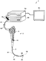
図1に示すように、内視鏡システム1は、内視鏡2と、プロセッサ5Aと、光源装置5Bと、モニタ5Cと、を具備する。内視鏡2は、細長い挿入部3を被検体の体腔内に挿入することによって、被検体の体内画像を撮像し撮像信号を出力する。
内視鏡2の挿入部3の基端側には、内視鏡2を操作する各種ボタン類が設けられた操作部4が配設されている。操作部4には、被検体の体腔内に生体鉗子、電気メスおよび検査プローブ等の処置具を挿入する鉗子管(チャンネル)22(図2参照)の処置具挿入口4Aがある。
挿入部3は、撮像素子50が配設されている先端部3Aと、先端部3Aの基端側に連設された湾曲自在な湾曲部3Bと、この湾曲部3Bの基端側に連設された可撓管部3Cとによって構成される。湾曲部3Bは、操作部4の操作によって湾曲する。なお、内視鏡2は、いわゆる軟性内視鏡だが、挿入部3が硬質な、いわゆる硬性内視鏡であってもよい。
操作部4の基端部側に配設されたユニバーサルコード4Bには、先端部3Aの撮像素子50と接続された信号ケーブル61が挿通している。
ユニバーサルコード4Bは、コネクタ4Cを介してプロセッサ5Aおよび光源装置5Bに接続される。プロセッサ5Aは内視鏡システム1の全体を制御するとともに、撮像素子50が出力する撮像信号に信号処理を行い画像信号として出力する。モニタ5Cは、プロセッサ5Aが出力する画像信号を表示する。
光源装置5Bは、例えば、白色LEDを有する。光源装置5Bが出射する光は、ユニバーサルコード4Bおよび挿入部3を挿通するライトガイド24、25(図3参照)を介して先端部3Aに導光され、被写体を照明する。
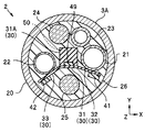
図2および図3に示すように、内視鏡2は、挿入部3の先端部3Aに筒体20を有し、筒体20の内部に、撮像素子50と、可撓性の配線板30と、先端部3Aを挿通している管状部材である吸引管21および鉗子管22と、が配設されている。なお、図2においては筒体20の内部に配設されている構成要素のうち、吸引管21および鉗子管22だけを示している。
筒体20の外面は外皮樹脂層(不図示)で覆われている。一方、筒体20の内部は封止樹脂26で封止されている。封止樹脂26は、エポキシ樹脂またはシリコーン樹脂等の耐湿性に優れた樹脂から選択される。
挿入部3の先端面には、吸引管21の開口21H、鉗子管22の開口22H、送水/送気管23の開口23T、ライトガイド24、25が導光した照明光を出射する照明光学系24T、25Tの先端面および撮像素子50に被写体像を結像する対物光学系52の先端面がある。吸引管21、送水/送気管23は、挿入部3およびユニバーサルコード4Bを挿通し、図示しない吸引ポンプ、送水/送気ポンプと接続されている。すなわち、吸引管21、鉗子管22、および送水/送気管23は、先端部3Aを挿通し先端面に開口を有する。
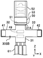
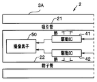
配線板30は、先端領域31Aを含む中間部31と、中間部31の両側辺から、それぞれ延設されている延設部32、33とからなる。中間部31にはチップコンデンサ49が、先端領域31Aには撮像素子30が、延設部32には駆動IC41が、延設部33には駆動IC42が、それぞれ配設されている。
図4Aおよび図4Bに示すように、先端部3Aの筒体20に挿入される前の製造途中の配線板30の中間部31の主面と延設部32、33の主面とは同一平面上にある。ただし、配線板30の中間部31の先端領域31Aは折り曲げられて、カバーガラス53が受光面に配設されている撮像素子50の裏面と接着されている。
撮像素子50は、CCDまたはCMOSセンサ等の受光部51が形成されている略直方体のチップである。なお、撮像素子50は裏面照射型であってもよい。撮像素子50の受光面には、カバーガラス53を介して、複数のレンズを含む対物光学系52が配設されている。
配線板30は、中間部31と、中間部31の側辺から延設されている延設部32、33と、を含む略十字型である。なお、配線板30は、片面配線板でもよいし、多層配線板でもよいし、電子部品内蔵配線板でもよい。
可撓性の配線板30は、例えばポリイミドを基体とし、例えば銅からなる配線パターンが両面に配設されている。配線板30は、先端領域31Aが撮像素子50の裏面と接着されており、後端領域にはケーブル61が接続されている。
配線板30の中間部31の先端領域31Aの主面は、中間部31の主面に対して90度折れ曲がっている。そして、図示しないが、撮像素子50の裏面に配置された外部電極と、配線板30の先端電極とが接合されている。撮像素子50と配線板30との電気的接続は、前記構成に限られるものではなく、例えば、配線板30の先端面から突出したフライングリードが撮像素子50の受光面の外部電極と接合されていてもよい。なお、フライングリードが90度折れ曲がっていれば、配線板30の先端領域31Aが中間部31に対して折れ曲がっていなくともよい。
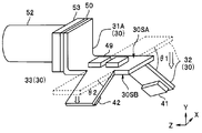
一方、延設部32の主面は中間部31の主面(第1の主面30SAおよび第2の主面30SB)に対して折れ曲がっており、その曲がり角度θ1(図5参照)は吸引管21に当接することによって規定されている。延設部33の主面も中間部31の主面に対して折れ曲がっており、その曲がり角度θ2(図5参照)は鉗子管22に当接することによって規定されている。
配線板30には複数の電子部品が配設されている。発熱量の少ない電子部品49、例えば受動部品であるチップコンデンサ等は配線板30の中間部31の第1の主面30SAに配設されているのに対して、能動部品である駆動IC41、42は延設部32、33の第2の主面30SBに配設されている。なお、駆動ICは周辺ICとよばれることもある集積回路((Integrated Circuit)部品である。
駆動IC41、42の配設位置は、撮像素子50の配設位置から大きく離れているが、延設部32、33は折れ曲がっているので、先端部3Aの径および長さは小さい。
駆動IC41は、配線板30に配設されている複数の電子部品のうち駆動時の発熱量が最も多い高発熱部品である。そして、駆動IC42は、駆動IC41と同じ発熱量または駆動IC41の次に発熱量が多い発熱部品である。撮像素子50が配設されている先端領域31Aから離れるように、発熱部品である駆動IC41、42は延設部32、33に配設されている。
そして、図3に示したように延設部32の第1の主面30SAは吸引管21の外面と当接しており、延設部32の第1の主面30SAは鉗子管22の外面と当接している。
吸引管21および鉗子管22は、熱伝導率の高い材料、例えば金属からなることが好ましい。しかし、吸引管21等は先端部3Aを挿通し先端面に開口を有するため空冷効果により、熱伝導率の比較的低い材料、例えば、PTFE等の樹脂材料から構成されていても放熱効率がよい。
図5に示すように、配線板30は、延設部32、33を折り曲げながら、すでに吸引管21および鉗子管22が挿通されている筒体20の内部に挿入される。なお、図5では信号ケーブル61等は図示していない。
図3に示したように、延設部32、33は配線板30の折り曲げ部の反発力により付勢され、吸引管21、鉗子管22に当接する。言い替えれば、延設部32、33の主面の中間部31の主面に対する曲がり角度θ1、θ2は、管状部材(吸引管21、鉗子管22)に当接することによって規定されている。
なお、可撓性の延設部32、33は付勢されているため、管状部材と当接したときに線接触ではなく、面接触する。管状部材と面接触している延設部32、33は、伝熱面積が広いため放熱効率がよい。
図6に示すように、内視鏡2では、発熱部品である駆動IC41、42が発生した熱は、吸引管21、鉗子管22を介して放熱される。すなわち、撮像素子50は発熱部品が発生した熱の伝熱経路に位置していない。
このため、駆動IC41、42が発生した熱は、吸引管21、鉗子管22との当接部分を介して伝熱される。駆動IC41、42が発生した熱は、撮像素子50には殆ど伝熱されないため、撮像素子50に悪影響を及ぼすおそれがない。
すなわち、内視鏡2は撮像素子50が過度の昇温によって劣化したり、また熱ノイズによって画像品質が悪化したりするおそれがない。
なお、配線板30の中間部31の側面から延設されている延設部32と延設部33とは、長さ、形状または曲がり角度の少なくともいずれかが異なっていてもよい。また、配線板30は1枚のフレキシブル配線板であるため、中間部31と延設部32、33との境界は明確に定義されるものではない。
また、撮像素子50に影響を及ぼすおそれのある高発熱部品が駆動IC41だけの場合には、延設部33は不要である。すなわち、中間部31の両側面から、それぞれ延設部が延設されている必要はない。言い替えれば、配線板は少なくとも1つの延設部を含んでいればよい。
これに対して3個以上の発熱部品がある場合には、3以上の延設部が延設されていてもよいし、1つの延設部に複数の発熱部品が配設されていてもよい。また、それぞれの延設部は、先端部3Aを挿通している管状部材のいずれかと当接していればよい。さらに、1本の管状部材に複数の延設部が当接していてもよい。
なお、配線板30は電気的接続のための配線パターン以外に、発熱部品の伝熱経路に沿って伝熱パターンを有していることが好ましい。すなわち、配線板30は電気的接続には寄与しない、例えば接地電位の伝熱パターンが配線パターンの周囲に配設されていることが好ましい。伝熱パターンは配線パターンと同じ銅、または金等の高熱伝導率材料からなる。
例えば、基体の表面の銅膜の不要な部分を除去して必要な部分を残し配線パターンとするサブトラクト法において、配線パターンの外周にそって額縁状にだけ銅膜を除去し、その周囲を残すことで、伝熱パターンが形成できる。
発熱部品の伝熱経路、すなわち、発熱部品の配設部から管状部材と当接している部分まで伝熱パターンのある配線板を有する内視鏡は、発熱部品が発生した熱を、より効率的に管状部材に伝熱できる。
ここで、図3に示したように、内視鏡2では、配線板30の延設部32、33の管状部材(吸引管21、鉗子管22)との当接部分よりも先端側に、発熱部品である駆動IC41、42が配設されている。言い替えれば、延設部32、33の中間部31の端辺から当接部分までの間には駆動IC41、42は配設されていない。
このため、内視鏡2は、特に発熱部品が発生した熱が撮像素子50に悪影響を及ぼすおそれがない。
なお、延設部32、33の中間部31の端辺から当接部分までの間には、発熱部品が発生した熱が中間部側に伝熱されるのを防止するため、伝熱パターンは形成されていないことが好ましい。
<第1実施形態の変形例>
次に第1実施形態の変形例の内視鏡2Aについて説明する。内視鏡2Aは内視鏡2と類似しているので同じ機能の構成要素には同じ符号を付し説明は省略する。
次に第1実施形態の変形例の内視鏡2Aについて説明する。内視鏡2Aは内視鏡2と類似しているので同じ機能の構成要素には同じ符号を付し説明は省略する。
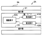
図7に示すように、内視鏡2Aは挿入部の先端部3Aに発熱部品である発光素子41Aを有する。
内視鏡2Aは、プロセッサ5Aへ伝送する信号量が多い高画素数の撮像素子50Aを有する。このため、信号ケーブル61を介した電気信号伝送ではケーブルの太さが太くなり、挿入部の細径化が容易ではなくなる。
内視鏡2Aでは、撮像素子50Aの出力した画像信号の伝送には、電気信号伝送ではなく、光信号による細い光ファイバを介した光信号伝送が用いられている。
このため、挿入部の先端部3Aには、電気信号を光信号に変換する発光素子41Aが配設されている。なお、内視鏡2Aでは、撮像素子50Aに供給されるクロック信号も、画像信号伝送と同じ光ファイバを介して先端部3Aに伝送される。このため、先端部3Aには光信号を電気信号に変換する受光素子42Aが配設されている。
LED等の発光素子41Aは発熱部品である。このため、図示しないが、発光素子41Aは、延設部32に配設されており、延設部32は吸引管21と当接している。
発光素子41Aが発生した熱は吸引管21に伝熱されるため、撮像素子50Aに悪影響を及ぼすおそれはない。
なお、フォトダイオード等の受光素子42Aは大きな熱を発生する素子ではない。このため、受光素子42Aは、鉗子管22等と当接している延設部に配設されている必要はないが、配設されていてもよい。また、内視鏡2Aが、発熱量の大きい駆動ICを更に有する場合には、駆動ICを管状部材と当接している延設部に配設することが好ましいことは言うまでも無い。
内視鏡2Aは、高画素数の撮像素子50Aを有するが光ファイバを介して信号を伝送するため細径である。そして、発熱素子である発光素子41Aを有するが、発光素子41Aが発生した熱の放熱経路に撮像素子50Aが位置していない。このため、撮像素子50Aは、発光素子41Aが発生した熱により、劣化したり、熱ノイズによって画像品質が悪化したりするおそれがない。
なお、先端部3Aに複数の発熱部品が配設される場合には、少なくとも発熱量の最も多い一の発熱部品が管状部材と当接している延設部に配設されていれば、上記効果が得られる。また発熱部品としては、駆動ICまたは発光素子に限られるものではない。
<第2実施形態>
次に第2実施形態の内視鏡2Bについて説明する。内視鏡2Bは内視鏡2と類似しているので同じ機能の構成要素には同じ符号を付し説明は省略する。
次に第2実施形態の内視鏡2Bについて説明する。内視鏡2Bは内視鏡2と類似しているので同じ機能の構成要素には同じ符号を付し説明は省略する。
図8に示すように、内視鏡2Bの配線板30Bは、延設部32B、33Bの発熱部品である駆動IC41、42が配設されている部分よりも更に先端側が、金属からなる筒体20の内面と面接触している。
このため、図9に示すように、駆動IC41、42が発生した熱は当接している管状部材(吸引管21、鉗子管22)だけでなく、筒体20を介して伝熱される。
なお、延設部32B、33Bの先端側には、例えば、銅からなる接地電位の導体膜が配設されていることが好ましい。熱伝導率の高い銅膜を介して熱が、より効率的に伝熱される。
内視鏡2Bは内視鏡2等の効果を有し、さらに駆動IC41、42が発生した熱により撮像素子50が劣化したり、また熱ノイズによって画像品質が悪化したりするおそれがない。
本発明は上述した実施形態または変形例等に限定されるものではなく、本発明の要旨を変えない範囲において、種々の変更、改変等ができる。
1…内視鏡システム
2、2A、2B…内視鏡
3…挿入部
3A…先端部
20…筒体
21…吸引管
22…鉗子管
23…送気管
24…ライトガイド
26…封止樹脂
30…配線板
31…中間部
31A…先端領域
32、33…延設部
41、42…駆動IC
50…撮像素子
2、2A、2B…内視鏡
3…挿入部
3A…先端部
20…筒体
21…吸引管
22…鉗子管
23…送気管
24…ライトガイド
26…封止樹脂
30…配線板
31…中間部
31A…先端領域
32、33…延設部
41、42…駆動IC
50…撮像素子
Claims (7)
- 挿入部の先端部に筒体を有し、前記筒体の内部に、撮像素子と、可撓性の配線板と、前記先端部を挿通している管状部材と、が配設された内視鏡であって、
前記配線板が、前記撮像素子と接続されている中間部と、前記中間部の側辺から延設されている延設部と、を含み、
発熱部品が配設されている前記延設部が前記管状部材と当接していることを特徴とする内視鏡。 - 前記延設部の前記管状部材との当接部分よりも先端側に、前記発熱部品が配設されていることを特徴とする請求項1に記載の内視鏡。
- 前記延設部の主面が前記中間部の主面に対して折れ曲がっており、その曲がり角度が、前記管状部材に当接することによって規定されていることを特徴とする請求項1または請求項2に記載の内視鏡。
- 前記延設部の前記発熱部品が配設されている部分よりも更に先端側が、前記筒体の内面と面接触していることを特徴とする請求項1から請求項3のいずれか1項に記載の内視鏡。
- 前記発熱部品が、前記撮像素子に駆動信号を供給する集積回路部品であることを特徴とする請求項1から請求項4のいずれか1項に記載の内視鏡。
- 前記発熱部品が、前記撮像素子からの電気信号を光信号に変換する発光素子であることを特徴とする請求項1から請求項4のいずれか1項に記載の内視鏡。
- 前記配線板が、前記中間部のそれぞれの側辺から延設されている前記延設部を含み、
前記延設部にそれぞれ前記発熱部品が配設されていることを特徴とする請求項1から請求項6のいずれか1項に記載の内視鏡。
Priority Applications (2)
| Application Number | Priority Date | Filing Date | Title |
|---|---|---|---|
| JP2017524171A JP6512522B2 (ja) | 2015-06-16 | 2015-06-16 | 内視鏡 |
| PCT/JP2015/067252 WO2016203535A1 (ja) | 2015-06-16 | 2015-06-16 | 内視鏡 |
Applications Claiming Priority (1)
| Application Number | Priority Date | Filing Date | Title |
|---|---|---|---|
| PCT/JP2015/067252 WO2016203535A1 (ja) | 2015-06-16 | 2015-06-16 | 内視鏡 |
Publications (1)
| Publication Number | Publication Date |
|---|---|
| WO2016203535A1 true WO2016203535A1 (ja) | 2016-12-22 |
Family
ID=57546632
Family Applications (1)
| Application Number | Title | Priority Date | Filing Date |
|---|---|---|---|
| PCT/JP2015/067252 Ceased WO2016203535A1 (ja) | 2015-06-16 | 2015-06-16 | 内視鏡 |
Country Status (2)
| Country | Link |
|---|---|
| JP (1) | JP6512522B2 (ja) |
| WO (1) | WO2016203535A1 (ja) |
Cited By (1)
| Publication number | Priority date | Publication date | Assignee | Title |
|---|---|---|---|---|
| JP2021045339A (ja) * | 2019-09-18 | 2021-03-25 | Hoya株式会社 | 内視鏡、内視鏡用プロセッサ及び内視鏡システム |
Citations (6)
| Publication number | Priority date | Publication date | Assignee | Title |
|---|---|---|---|---|
| JP2002112957A (ja) * | 2000-10-12 | 2002-04-16 | Olympus Optical Co Ltd | 電子内視鏡システム |
| JP2010022815A (ja) * | 2008-06-18 | 2010-02-04 | Olympus Corp | 内視鏡装置 |
| JP2010069217A (ja) * | 2008-09-22 | 2010-04-02 | Fujifilm Corp | 電子内視鏡用撮像装置、および電子内視鏡 |
| JP2011200401A (ja) * | 2010-03-25 | 2011-10-13 | Fujifilm Corp | 内視鏡 |
| JP2012071064A (ja) * | 2010-09-29 | 2012-04-12 | Fujifilm Corp | 内視鏡装置及びその撮像素子放熱方法 |
| JP2013233343A (ja) * | 2012-05-10 | 2013-11-21 | Fujifilm Corp | 電子内視鏡装置及び撮像素子の放熱方法 |
-
2015
- 2015-06-16 WO PCT/JP2015/067252 patent/WO2016203535A1/ja not_active Ceased
- 2015-06-16 JP JP2017524171A patent/JP6512522B2/ja active Active
Patent Citations (6)
| Publication number | Priority date | Publication date | Assignee | Title |
|---|---|---|---|---|
| JP2002112957A (ja) * | 2000-10-12 | 2002-04-16 | Olympus Optical Co Ltd | 電子内視鏡システム |
| JP2010022815A (ja) * | 2008-06-18 | 2010-02-04 | Olympus Corp | 内視鏡装置 |
| JP2010069217A (ja) * | 2008-09-22 | 2010-04-02 | Fujifilm Corp | 電子内視鏡用撮像装置、および電子内視鏡 |
| JP2011200401A (ja) * | 2010-03-25 | 2011-10-13 | Fujifilm Corp | 内視鏡 |
| JP2012071064A (ja) * | 2010-09-29 | 2012-04-12 | Fujifilm Corp | 内視鏡装置及びその撮像素子放熱方法 |
| JP2013233343A (ja) * | 2012-05-10 | 2013-11-21 | Fujifilm Corp | 電子内視鏡装置及び撮像素子の放熱方法 |
Cited By (2)
| Publication number | Priority date | Publication date | Assignee | Title |
|---|---|---|---|---|
| JP2021045339A (ja) * | 2019-09-18 | 2021-03-25 | Hoya株式会社 | 内視鏡、内視鏡用プロセッサ及び内視鏡システム |
| JP7353886B2 (ja) | 2019-09-18 | 2023-10-02 | Hoya株式会社 | 内視鏡及び内視鏡システム |
Also Published As
| Publication number | Publication date |
|---|---|
| JP6512522B2 (ja) | 2019-05-15 |
| JPWO2016203535A1 (ja) | 2018-04-05 |
Similar Documents
| Publication | Publication Date | Title |
|---|---|---|
| US9345395B2 (en) | Imaging module and endoscope device | |
| US10281710B2 (en) | Imaging module and endoscope apparatus each having a flexible substrate divided into different regions where a chip having a transmission buffer and a drive signal cable are connected to the different regions | |
| JP5775984B1 (ja) | 内視鏡装置 | |
| JP5964003B1 (ja) | 撮像ユニット、撮像モジュールおよび内視鏡システム | |
| US11653825B2 (en) | Imaging unit and oblique-viewing endoscope | |
| JP2010069217A (ja) | 電子内視鏡用撮像装置、および電子内視鏡 | |
| US10617285B2 (en) | Imaging module with multi-layer substrate and endoscope apparatus | |
| US10925464B2 (en) | Imaging unit and endoscope | |
| US20170255001A1 (en) | Imaging unit, endoscope, and method of manufacturing imaging unit | |
| JP2011200401A (ja) | 内視鏡 | |
| JP4709870B2 (ja) | 撮像装置 | |
| JP6324644B1 (ja) | 撮像ユニットおよび内視鏡 | |
| JP6512522B2 (ja) | 内視鏡 | |
| US11857166B2 (en) | Imaging unit and endoscope | |
| JP4127776B2 (ja) | 撮像装置 | |
| JP6099541B2 (ja) | 内視鏡及び内視鏡の製造方法 | |
| WO2017115441A1 (ja) | 実装構造体、撮像装置および内視鏡 | |
| JP2011200338A (ja) | 電子内視鏡 | |
| US20170360284A1 (en) | Endoscope device | |
| JP5767426B1 (ja) | 撮像ユニット | |
| JP2022142206A (ja) | 撮像モジュール | |
| JP6503205B2 (ja) | 撮像装置 |
Legal Events
| Date | Code | Title | Description |
|---|---|---|---|
| 121 | Ep: the epo has been informed by wipo that ep was designated in this application |
Ref document number: 15895556 Country of ref document: EP Kind code of ref document: A1 |
|
| ENP | Entry into the national phase |
Ref document number: 2017524171 Country of ref document: JP Kind code of ref document: A |
|
| NENP | Non-entry into the national phase |
Ref country code: DE |
|
| 122 | Ep: pct application non-entry in european phase |
Ref document number: 15895556 Country of ref document: EP Kind code of ref document: A1 |