WO2016199916A1 - イオン注入装置 - Google Patents
イオン注入装置 Download PDFInfo
- Publication number
- WO2016199916A1 WO2016199916A1 PCT/JP2016/067435 JP2016067435W WO2016199916A1 WO 2016199916 A1 WO2016199916 A1 WO 2016199916A1 JP 2016067435 W JP2016067435 W JP 2016067435W WO 2016199916 A1 WO2016199916 A1 WO 2016199916A1
- Authority
- WO
- WIPO (PCT)
- Prior art keywords
- laser
- ion
- ion implantation
- particles
- implantation apparatus
- Prior art date
- Legal status (The legal status is an assumption and is not a legal conclusion. Google has not performed a legal analysis and makes no representation as to the accuracy of the status listed.)
- Ceased
Links
Images






Classifications
-
- H—ELECTRICITY
- H01—ELECTRIC ELEMENTS
- H01J—ELECTRIC DISCHARGE TUBES OR DISCHARGE LAMPS
- H01J37/00—Discharge tubes with provision for introducing objects or material to be exposed to the discharge, e.g. for the purpose of examination or processing thereof
- H01J37/30—Electron-beam or ion-beam tubes for localised treatment of objects
- H01J37/317—Electron-beam or ion-beam tubes for localised treatment of objects for changing properties of the objects or for applying thin layers thereon, e.g. for ion implantation
-
- H—ELECTRICITY
- H10—SEMICONDUCTOR DEVICES; ELECTRIC SOLID-STATE DEVICES NOT OTHERWISE PROVIDED FOR
- H10P—GENERIC PROCESSES OR APPARATUS FOR THE MANUFACTURE OR TREATMENT OF DEVICES COVERED BY CLASS H10
- H10P30/00—Ion implantation into wafers, substrates or parts of devices
- H10P30/20—Ion implantation into wafers, substrates or parts of devices into semiconductor materials, e.g. for doping
Definitions
- the present invention relates to an ion implantation apparatus.
- a process of implanting ions into the semiconductor wafer (hereinafter sometimes referred to as an “ion implantation process”) is standard for the purpose of changing the conductivity and the purpose of changing the crystal structure of the semiconductor wafer.
- An apparatus used in the ion implantation process is called an ion implantation apparatus, which generates ions by an ion source, accelerates the generated ions to form an ion beam, and transports the ion beam to a vacuum processing chamber. And a function of irradiating the wafer in the processing chamber with an ion beam.
- particles may be generated due to various factors. If particles generated in the vacuum chamber float and adhere to the wafer surface, the resist pattern on the wafer surface may be damaged or uniform ion implantation may be hindered. As a result, the yield of the ion implantation process may be reduced.
- One exemplary object of an aspect of the present invention is to provide a technique for suppressing a decrease in productivity due to generation of particles.
- An ion implantation apparatus includes a beam line device configured to transport an ion beam toward a wafer, and a direction intersecting a traveling direction of the ion beam toward the ion beam transported by the beam line device. And a laser irradiation device configured to irradiate the laser beam. The laser irradiation device irradiates laser light on particles generated in the beam line device and flying toward the wafer, thereby preventing the particles from adhering to the wafer as they are.
- Another embodiment of the present invention is also an ion implantation apparatus.
- This apparatus applies an electric field to the ion beam incident through the front beam path and deflects the ion beam so that the ion beam is emitted through the rear beam path toward the wafer, and on the downstream side of the beam deflection apparatus.
- An incident window and an emission window provided at respective positions facing each other across the latter beam path, and the ion beam in the latter beam path are irradiated with the laser beam through the incident window, and the irradiated laser beam is emitted from the emission window.
- a laser irradiation device configured to emit light.
- the adhesion of particles to the wafer can be prevented and the productivity of the ion implantation process can be improved.
- FIGS. 1A and 1B are a top view and a side view schematically showing a configuration of an ion implantation apparatus according to an embodiment. It is a side view which shows roughly the structure of the ion implantation apparatus which concerns on a modification. It is a top view which shows roughly the structure of the ion implantation apparatus which concerns on a modification. It is sectional drawing which shows the structure of the ion implantation apparatus of FIG. 3 roughly. It is a top view which shows roughly the structure of the ion implantation apparatus which concerns on a modification.
- FIG. 6 is a cross-sectional view schematically showing a configuration of the ion implantation apparatus of FIG. 5.
- the ion implantation apparatus includes a beam line apparatus configured to transport an ion beam toward a wafer.
- a resist mask or the like for selectively performing ion implantation at a desired position on the wafer is generally provided on the surface of the wafer to be subjected to ion implantation.
- a part of the resist mask is scattered by irradiation with an ion beam, and gas molecules called resist outgas are generated.
- the beam line device is provided with electrodes such as deflection means for deflecting the ion beam by the action of an electric field.
- electrodes such as deflection means for deflecting the ion beam by the action of an electric field.
- a part of the resist outgas described above may be deposited on the electrode portion due to the action of an electric field or the like, thereby forming a clustered deposit.
- a part of the deposit is scattered by discharge generated in the electrode portion and floats in the beam line device as particles. If these particles adhere to the surface of the wafer, the resist pattern on the wafer surface may be damaged, or uniform ion implantation may be hindered by blocking ion beam irradiation. If it does so, the manufacture yield of an ion implantation process may fall and it may affect productivity.
- the ion implantation apparatus includes a laser irradiation apparatus configured to irradiate a laser beam in a direction intersecting the traveling direction of the ion beam toward the ion beam transported by the beam line apparatus.
- the laser irradiation device irradiates laser light on particles generated in the beam line device and flying toward the wafer, thereby preventing the particles from adhering to the wafer as they are. More specifically, a radiation pressure is applied to the particles by laser light irradiation to change the trajectory of the particles so that the particles do not face the wafer.
- the particles are heated by laser irradiation to be decomposed or evaporated to reduce the particle size of the particles toward the wafer. Thereby, the yield reduction due to the adhesion of particles is suppressed, and the productivity of the ion implantation process is improved.
- FIG. 1 is a diagram schematically showing an ion implantation apparatus 10 according to an embodiment.
- FIG. 1A is a top view illustrating a schematic configuration of the ion implantation apparatus 10
- FIG. 1B is a side view illustrating a schematic configuration of the ion implantation apparatus 10.
- the ion implantation apparatus 10 is configured to perform ion implantation processing on the surface of the workpiece W.
- the workpiece W is, for example, a substrate, for example, a semiconductor wafer. Therefore, in the following description, the workpiece W may be referred to as a substrate W for convenience of explanation, but this is not intended to limit the target of the implantation process to a specific object.
- the ion implantation apparatus 10 is configured to irradiate the ion beam B over the entire wafer W by reciprocating scanning of the beam and reciprocating movement of the wafer W.
- the reciprocating scanning of the beam is performed in the direction of the arrow X
- the reciprocating motion of the wafer W is performed in the direction of the arrow Y.
- the ion implantation apparatus 10 includes an ion source 12, a beam line apparatus 14, and an implantation processing chamber 16.
- the ion source 12 is configured to provide an ion beam B to the beam line device 14.
- the beam line device 14 is configured to transport ions from the ion source 12 to the implantation processing chamber 16.
- the ion implantation apparatus 10 includes a vacuum exhaust system (not shown) for providing a desired vacuum environment to the ion source 12, the beam line device 14, and the implantation processing chamber 16.
- the beam line device 14 includes, in order from the upstream, the mass analysis unit 18, the beam shaping unit 20, the beam measurement unit 22, the beam scanner 24, the collimating lens 30 or the beam collimating device, and an angular energy filter (AEF; Angular (Energy Filter) 34 is provided.
- AEF Angular energy filter
- the upstream side of the beam line device 14 indicates the side close to the ion source 12, and the downstream side indicates the side close to the implantation processing chamber 16 (or the beam stopper 38).
- the mass analyzer 18 is provided downstream of the ion source 12 and is configured to select a necessary ion species from the ion beam B extracted from the ion source 12 by mass spectrometry.
- the beam shaping unit 20 includes a converging lens such as a quadrupole focusing device (Q lens), and is configured to shape the ion beam B into a desired cross-sectional shape.
- the beam measuring unit 22 is arranged so as to be able to be taken in and out of the beam line, and measures the intensity or current of the ion beam.
- the beam measurement unit 22 includes a Faraday cup 22b that measures a beam current and a drive unit 22a that moves the Faraday cup 22b up and down.
- the beam measuring unit 22 also functions as a blocking means for the ion beam B.
- the beam scanner 24 is configured to provide reciprocal scanning of the beam, and is a deflecting unit that scans the shaped ion beam B in the x direction.
- the beam scanner 24 has a pair of scanning electrodes 26 provided to face each other in the x direction.
- the scan electrode pair 26 is connected to a variable voltage power source (not shown).
- a variable voltage power source not shown.
- the electric field generated between the electrodes is changed to change the ion beam B.
- the ion beam B is scanned over the scanning range in the x direction.
- an arrow X indicates the beam scanning direction and scanning range, and a plurality of trajectories of the ion beam B in the scanning range are indicated by alternate long and short dash lines.
- the beam scanner 24 may be a magnetic field type deflection unit that scans an ion beam by applying a magnetic field.
- the beam scanner 24 has a beam damper 28 provided outside the opening 24a through which the scanning ion beam B passes.
- the beam damper 28 is provided at a location where the ion beam B collides when the ion beam B is deflected beyond the scanning range in the x direction in which the beam is scanned.
- the beam damper 28 is made of a material such as graphite (C) that is less likely to be sputtered by an ion beam collision.
- a broken line arrow B ′ indicates the trajectory of the ion beam when it collides with the beam damper 28.
- the beam scanner 24 When the beam scanner 24 is operated so that the ion beam B collides with the beam damper 28, the ion beam B comes off the beam line and is interrupted on the way. Therefore, the beam scanner 24 also functions as a blocking means for the ion beam B. If the beam scanner 24 is operated so that the ion beam B is scanned in the normal scanning range, that is, if the beam scanner 24 is operated so that the ion beam B is emitted from the opening 24a. The blocking of the ion beam B is released.
- the collimating lens 30 is configured to make the traveling direction of the scanned ion beam B parallel.
- the collimating lens 30 has a plurality of arc-shaped collimating lens electrodes 32 each having an ion beam passage slit at the center.
- the collimating lens electrode 32 is connected to a high-voltage power supply (not shown), and applies an electric field generated by voltage application to the ion beam B to adjust the traveling direction of the ion beam B in parallel.
- the angle energy filter (AEF) 34 is configured to analyze the energy of the ion beam B, deflect ions of necessary energy downward, and guide the ions to the implantation processing chamber 16. Therefore, the angular energy filter 34 functions as a beam deflecting device.
- the angular energy filter 34 has an AEF electrode pair 36 for electric field deflection.
- the AEF electrode pair 36 is connected to a high voltage power source (not shown).
- the ion beam B is deflected downward by applying a positive voltage to the upper AEF electrode and a negative voltage to the lower AEF electrode.
- the angular energy filter 34 may be configured by a magnetic device for magnetic field deflection, or may be configured by a combination of an AEF electrode pair for electric field deflection and a magnet device.
- a path through which an ion beam incident on the angular energy filter 34 passes is also referred to as a “previous beam path”, and a path through which the ion beam emitted from the angular energy filter 34 passes is also referred to as a “back beam path”.
- the traveling direction of the ion beam passing through the front beam path and the traveling direction of the ion beam passing through the rear beam path are shifted in the y direction by the action of the electric field generated by the AEF electrode pair 36, and the deflection angle ⁇ is about 10 to 20 degrees.
- the beam line device 14 supplies the ion beam B to be irradiated onto the wafer W to the implantation processing chamber 16.
- the injection processing chamber 16 is provided with a beam stopper 38, a plasma shower device 40, an energy slit 42, and a reciprocating device 44.
- the reciprocating device 44 is configured to hold one or a plurality of wafers W and provide relative movement (for example, y direction) with respect to the ion beam B to the wafers W as needed.
- FIG. 1B the reciprocating motion of the wafer W is illustrated by the arrow Y.
- the ion beam B is incident on the beam stopper 38.
- the plasma shower apparatus 40 supplies low energy electrons to the front surface of the ion beam and the wafer W according to the amount of beam current of the ion beam B, and suppresses the charge-up of positive charges on the surface of the wafer W caused by ion implantation.
- the energy slit 42 is an energy limiting slit (EDS) defined by a horizontally long slit in the beam scanning direction (x direction).
- EDS energy limiting slit
- the energy slit 42 partially shields the beam traveling in the subsequent beam path toward the wafer, and allows a beam component having a predetermined trajectory to pass through the beam in the subsequent beam path toward the wafer. Thereby, the passage of the ion beam having the energy value and the valence other than the intended one is limited, and only the ion beam having the desired energy value and the valence that has passed through the angular energy filter 34 is separated. Therefore, the energy slit 42 performs energy analysis of the ion beam incident on the wafer W together with the angular energy filter 34.
- the ion implantation apparatus 10 further includes a laser irradiation device 50, an entrance window 52, an exit window 54, a laser damper 56, and a photodetector 58.
- the entrance window 52 and the exit window 54 are provided on a part of the wall surface of the chamber constituting the injection processing chamber 16.
- the entrance window 52 and the exit window 54 are provided on the downstream side of the angular energy filter 34 and are provided at positions facing the x direction across the trajectory of the ion beam B.
- the entrance window 52 and the exit window 54 are made of a material that is transparent to the wavelength of the laser beam output from the laser irradiation device 50.
- the laser irradiation device 50 includes a laser light source that can output a high-power laser beam, and includes, for example, a laser oscillator such as a YAG laser, a CO 2 laser, a fiber laser, or a semiconductor laser.
- the laser irradiation device 50 is arranged so as to irradiate the laser beam L toward the ion beam B in a direction crossing the traveling direction of the ion beam.
- the laser light L output from the laser irradiation device 50 is introduced into the implantation processing chamber 16 through the incident window 52 and is emitted to the outside of the implantation processing chamber 16 through the emission window 54.
- Laser light L emitted from the emission window 54 is absorbed by the laser damper 56. Therefore, the laser beam L from the laser irradiation apparatus 50 is irradiated in the horizontal direction (x direction) toward the trajectory of the ion beam B.
- the laser irradiation device 50 irradiates the laser beam L toward the particle 70 generated inside the beam line device 14 or the implantation processing chamber 16 and flying toward the wafer W.
- the particles 70 are generated, for example, in the AEF 34 to which a high voltage is applied, and travel toward the wafer W along the trajectory of the ion beam B.
- the laser irradiation device 50 applies a radiation pressure in the x direction to the particles 70 by irradiating the particles 70 with laser light in the horizontal direction (x direction). As a result, the momentum in the x direction is added to the particles 70, and the direction in which the particles 70 fly changes to the x direction.
- the particles 70 fly in a direction that does not reach the wafer W.
- the particles 70 fly toward and collide with the energy slit 42 located in front of the wafer W and the inner wall of the plasma shower apparatus 40.
- the laser irradiation device 50 changes the flying direction of the particles 70 and prevents the particles 70 from adhering to the surface of the wafer W.
- the laser irradiation device 50 may apply energy to the particles 70 by irradiation of the laser light L, and decompose or evaporate the particles 70.
- the particle 70 is decomposed into a plurality of particles having a smaller particle diameter, or the particle 70 is evaporated. Or may be gasified.
- the laser irradiation apparatus 50 may be configured to decompose or evaporate the particles 70 having a particle size of about several tens of nm to several ⁇ m so that the particle size becomes several nm to several tens of nm or less.
- the laser irradiation apparatus 50 may decompose the particles 70 by irradiation with the laser light L, and may prevent the particle trajectory generated after the decomposition from facing the wafer W.
- the photodetector 58 is arranged so as to detect the scattered light S from the particles 70 floating inside the beam line device 14 or the injection processing chamber 16.
- the photodetector 58 is provided in the vicinity of the optical path of the laser light L from the laser irradiation device 50 toward the laser damper 56 and at a position off the optical path of the laser light L.
- the photodetector 58 is arranged so as to detect the scattered light S emitted through the emission window 54, for example.
- the photodetector 58 may be disposed at a position where scattered light emitted through the incident window 52 can be detected, or may be disposed inside the beam line device 14 or the implantation processing chamber 16.
- the control device 60 controls the operation of each device constituting the ion implantation device 10.
- the control device 60 stops the irradiation of the ion beam B by operating beam blocking means such as the beam measuring unit 22 and the beam scanner 24 according to the detection result of the photodetector 58.
- the control device 60 stops the irradiation of the ion beam B when the intensity of the scattered light detected by the photodetector 58 exceeds a predetermined threshold level or when the period exceeding the predetermined threshold level exceeds the reference time. .
- the condition for stopping the irradiation of the ion beam B is set as a value at which many particles are detected to such an extent that the yield of the ion implantation process can be greatly reduced.
- the control device 60 may also stop the output of the laser light L from the laser irradiation device 50 at the same time.
- the ion implantation apparatus 10 irradiates the laser beam L toward the ion beam B during the ion implantation process of irradiating the wafer W with the ion beam B, and flies toward the wafer W along the ion beam B.
- the particles 70 are prevented from adhering to the wafer W as they are.
- the yield is prevented by preventing the adhesion of particles. Can be suppressed.
- the ion implantation apparatus 10 monitors the state of particles flying toward the wafer W by detecting the scattered light of the laser light irradiated toward the ion beam B. As a result, a situation in which the number of particles toward the wafer W increases is detected, and maintenance such as cleaning of the beam line device 14 and the implantation processing chamber 16 and replacement of parts can be taken at an appropriate timing. Further, when the number of particles directed to the wafer W increases and appropriate ion implantation processing may not be performed, the irradiation of the ion beam B is stopped to prevent the wafer W to be used from being wasted. be able to. Thereby, the manufacturing yield of the ion implantation apparatus 10 can be improved.
- the ion implantation apparatus 10 is configured such that the laser irradiation apparatus 50 is disposed outside the beam line apparatus 14 and the implantation processing chamber 16. For this reason, since it is not necessary to place the laser irradiation apparatus 50 in a vacuum environment, handling of the laser irradiation apparatus 50 can be facilitated. In addition, since the high-power laser beam L from the laser irradiation device 50 is emitted outside the implantation processing chamber 16 through the emission window 54, the laser beam is reflected in the beam line device 14 or the implantation processing chamber 16. It is possible to prevent hitting an unintended part. As a result, it is possible to suppress the influence of the laser beam being applied to the constituent devices of the ion implantation apparatus 10 and being damaged.
- FIG. 2 is a top view schematically showing a configuration of an ion implantation apparatus 110 according to a modification.
- the entrance window 152 and the exit window 154 are provided on the wall surface of the chamber constituting the beam line device 14, and the laser light L from the laser irradiation device 150 is irradiated to a position immediately downstream of the angular energy filter 34.
- This is different from the above-described embodiment.
- this modification will be described focusing on differences from the above-described embodiment.
- the entrance window 152 and the exit window 154 are arranged opposite to each other in the horizontal direction (x direction) with the downstream beam path interposed therebetween at a position immediately downstream of the angular energy filter 34.
- the laser beam L from the laser irradiation device 150 is irradiated in the horizontal direction onto the subsequent beam path through the incident window 152.
- the laser light L that has passed through the latter beam path is output to the outside of the beam line device 14 through the emission window 154 and is absorbed by the laser damper 156.
- the scattered light S from the particles is detected by the photodetector 158 through the exit window 154.
- the laser light L is irradiated at a position closer to the angular energy filter 34 that can be a particle generation source, so that the amount of particle displacement due to laser irradiation can be smaller than in the above-described embodiment. .
- the distance from the laser irradiation position to the wafer W is longer than that in the above-described embodiment, and the amount of displacement necessary to change the angle in the particle flying direction is small. Therefore, according to this modification, it is possible to suitably change the direction in which the particles fly with less power than in the above-described embodiment.
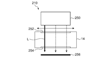
- FIG. 3 is a side view schematically showing a configuration of an ion implantation apparatus 210 according to a modification.
- This modification is different from the above-described embodiment and modification in that the laser beam L from the laser irradiation device 250 is irradiated in the vertical direction (y direction) toward the ion beam B.
- this modification will be described focusing on differences from the above-described embodiments and modifications.
- the entrance window 252 and the exit window 254 are arranged at positions downstream of the angular energy filter 34 so as to face each other in the vertical direction (y direction) with the downstream beam path interposed therebetween.
- the entrance window 252 is disposed on the upper side in the vertical direction
- the exit window 254 is disposed on the lower side in the vertical direction.
- the laser irradiation device 250 outputs the laser light L downward in the vertical direction, and applies a downward radiation pressure to the particles traveling along the subsequent beam path.
- the laser irradiation apparatus 250 is configured to apply a radiation pressure in the same direction as the deflection direction of the ion beam B by the angular energy filter 34 to the particles.
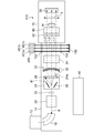
- FIG. 4 is a cross-sectional view schematically showing a configuration of the ion implantation apparatus 210, and shows a cross section taken along line AA of FIG.
- the laser irradiation device 250 is configured to be able to irradiate the laser beam L over the scanning direction of the ion beam B.
- the laser irradiation device 250 has a laser scanning mechanism that can scan the emission position of the laser light L in the x direction, for example.
- This laser scanning mechanism is composed of, for example, a polygon mirror and an f- ⁇ lens.
- the laser irradiation apparatus 250 when the laser irradiation apparatus 250 is provided with a fiber laser, you may comprise so that a laser beam can be irradiated over a x direction by scanning the exit port of a fiber laser in a x direction. Moreover, the laser irradiation apparatus 250 may be configured to irradiate a plurality of laser beams L over the x direction by including a plurality of laser light sources arranged side by side in the x direction.
- the laser irradiation device 250 applies radiation pressure in the same direction as the deflection direction of the angular energy filter 34 to the particles, the amount of particle displacement caused by laser irradiation is smaller than in the above-described embodiment. That's it. Since the energy slit 42 and the plasma shower device 40 whose opening width in the y direction is limited are provided downstream of the laser irradiation position, the energy slit 42 and the plasma shower device 40 are collided even with a smaller displacement amount. This is because the direction in which the particles fly can be changed. In addition, by setting the particle displacement direction by laser irradiation downward, it is possible to use the gravity acting on the particles until the particles reach the wafer W. Therefore, according to this modification, it is possible to suitably change the direction in which the particles fly with less power.
- FIG. 5 is a top view schematically showing a configuration of an ion implantation apparatus 310 according to a modification.
- the present modification is configured such that the laser beam from the laser irradiation device 150 is folded back and irradiated with the laser beam along a plurality of optical paths L1, L2, and L3 intersecting with the traveling direction of the ion beam B. It differs from the above-mentioned embodiment and modification.
- this modification will be described focusing on differences from the above-described embodiments and modifications.
- the entrance window 152 and the exit window 154 are arranged opposite to each other in the horizontal direction (x direction) with the downstream beam path interposed therebetween at a position immediately downstream of the angular energy filter 34.
- the plurality of optical paths L1 to L3 are provided so as to pass through both the entrance window 152 and the exit window 154, and are provided so as to extend in the horizontal direction.
- the first optical path L1 is provided on the upstream side near the angular energy filter 34
- the third optical path L3 is provided on the downstream side near the energy slit 42
- the second optical path L2 is the first optical path L1 and the third optical path L3. It is provided between.
- the plurality of optical paths L1 to L3 are provided so as to be parallel to each other, for example.
- the laser irradiation device 150 outputs laser light toward the incident window 152.
- the direction of the laser light output from the laser irradiation device 150 is changed by the plurality of mirrors 371, 372, 373, and 374, and sequentially passes through the plurality of optical paths L1 to L3.
- the plurality of mirrors 371 to 374 are arranged outside the beam line device 14.
- the first mirror 371 reflects the laser light emitted from the emission window 154 along the first optical path L1 so that the laser light is directed to the second mirror 372.
- the second mirror 372 reflects the laser light from the first mirror 371 so that the laser light enters the emission window 154 along the second optical path L2.
- the third mirror 373 reflects the laser light emitted from the incident window 152 along the second optical path L2, and directs the laser light to the fourth mirror 374.
- the fourth mirror 374 reflects the laser beam from the third mirror 373 so that the laser beam enters the incident window 152 along the third optical path L3.
- the laser light from the laser irradiation device 150 follows a one-stroke path that sequentially passes through the plurality of optical paths L1 to L3 by the optical arrangement described above.
- the laser beam is irradiated in the first direction from the incident window 152 toward the emission window 154.
- laser light is irradiated in a second direction (opposite to the first direction) from the exit window 154 toward the entrance window 152.
- the laser beam is sequentially passed through the plurality of optical paths L1 to L3 by using one or more optical elements arranged at least partially different from the illustrated configuration.
- a reflective optical element such as a mirror may be used, or a transmissive optical element such as a lens or a prism may be used.
- a plurality of optical paths through which the laser light passes may be configured to extend in the vertical direction instead of the horizontal direction.
- the number of optical paths of the laser beam that intersects the beam line device 14 may be two, or four or more.
- one or more arbitrary optical elements may be appropriately arranged depending on the number of laser beam folding (that is, the number of optical paths).
- At least a part of one or more optical elements that define an optical path through which the laser light passes may be provided inside the beam line device 14.
- a plurality of optical paths intersecting the beam line device 14 may be configured by repeatedly reflecting the laser light between two plane mirrors facing each other.
- the laser light traveling along the third optical path L3 exits from the exit window 154 and enters the measuring device 356.
- the measuring device 356 measures the light intensity and intensity distribution of the laser light output from the emission window 154.
- the measurement device 356 may be, for example, a power meter capable of measuring light intensity or a beam profiler capable of measuring light intensity distribution.
- the measuring device 356 detects, for example, whether an abnormality has occurred in the light source or the optical system by measuring the intensity or intensity distribution of the laser light.
- the measuring device 356 transmits information regarding the measured laser light to the control device 60.
- An incident window cover 362 that covers the inner surface 152 a of the incident window 152 is provided inside the incident window 152.
- an exit window cover 364 that covers the inner surface 154 a of the exit window 154 is provided inside the exit window 154.
- the entrance window cover 362 and the exit window cover 364 are made of a material that transmits laser light from the laser irradiation device 150, and are made of, for example, optical glass or resin film that is transparent to the wavelength of the laser light.
- a dielectric multilayer filter or the like for suppressing reflection of laser light may be provided on the surfaces of the entrance window cover 362 and the exit window cover 364.
- the entrance window cover 362 and the exit window cover 364 prevent the inside surfaces 152a and 154a of the entrance window 152 and the exit window 154 from being contaminated with the use of the ion implanter 310.
- the entrance window cover 362 and the exit window cover 364 are thermally connected to the cooling device 366.
- the cooling device 366 cools the entrance window cover 362 and the exit window cover 364 that can be heated by laser light irradiation, and suppresses the temperature rise of these window covers.
- the cooling device 366 may be configured to be thermally connected not only to the entrance window cover 362 and the exit window cover 364 but also to the entrance window 152 and the exit window 154 to cool the entrance window 152 and the exit window 154 at the same time. .
- FIG. 6 is a cross-sectional view schematically showing the configuration of the ion implantation apparatus 310, showing a cross section taken along line AA of FIG.
- An entrance window cover replacement mechanism 382 and an exit window cover replacement mechanism 384 are provided inside the beam line device 14.
- the incident window cover replacement mechanism 382 is configured to hold a plurality of replacement incident window covers 362b and replace the incident window cover 362a covering the incident window 152 with another incident window cover 362b. Further, the incident window cover replacement mechanism 382 may be configured to temporarily hold the used incident window cover 362a after replacement. As a result, the entrance window cover 362a becomes dirty due to the use of the ion implantation apparatus 310, and a decrease in the intensity of the laser light irradiated to the inside of the beam line apparatus 14 is suppressed.
- the incident window cover replacement mechanism 382 may be configured so that the incident window cover 362 can be replaced while the internal space of the beam line device 14 is maintained in a vacuum state. Thereby, the incident window cover 362 can be replaced without opening the beam line device 14 to the atmosphere, and an increase in maintenance man-hours and a decrease in the operating rate of the device due to the opening to the atmosphere can be suppressed.
- the exit window cover replacement mechanism 384 is configured in the same manner as the entrance window cover replacement mechanism 382.
- the exit window cover replacement mechanism 384 is configured to hold a plurality of exit window covers 364b and replace the exit window cover 364a covering the exit window 154 with another exit window cover 364b.
- the exit window cover replacement mechanism 384 suppresses a decrease in the intensity of the laser light applied to the inside of the beam line device 14 when the exit window cover 364a becomes dirty due to the use of the ion implantation apparatus 310.
- the entrance window cover 362 and the exit window cover 364 may be configured by a laminate of a plurality of cover members.
- This laminated body is configured so that a plurality of transparent resin films are temporarily fixed with an adhesive or the like, and the surface of the laminated body can be renewed by removing the resin films one by one. May be.
- the entrance window cover exchange mechanism 382 and the exit window cover exchange mechanism 384 may be configured so that a plurality of resin films constituting the laminate can be peeled one by one.
- the entrance window cover 362 and the exit window cover 364 may be constituted by a part of a continuous sheet wound around a roller.
- the entrance window cover replacement mechanism 382 and the exit window cover replacement mechanism 384 may include a feed roller for sending out a sheet serving as a window cover and a take-up roller for winding up the sent sheet.
- a part of the sheet stretched between the feeding roller and the take-up roller functions as a window cover, and replacement of the window cover is realized by operating the roller to update the sheet stretched between the rollers. May be.
- the window cover may be replaced by winding a part of the dirty sheet during use with the take-up roller and sending a new part of the unclean sheet from the feed roller.
- a photodetector 358 is provided for imaging a region irradiated with the laser light from the laser irradiation device 150.
- An imaging window 376 for enabling imaging by the photodetector 358 is provided on the wall surface of the beam line device 14.
- the photodetector 358 includes an imaging unit 358a such as a CCD or a CMOS sensor, and an analysis unit 358b that analyzes the size, quantity, speed, traveling direction, and the like of particles using the captured image. For example, the analysis unit 358b calculates information related to the velocity and the traveling direction of the particles by comparing a plurality of captured images continuously captured by the imaging unit 358a.
- the analysis unit 358b may calculate information regarding the number, size, or size distribution of particles by statistically processing the captured image of the imaging unit 358a. In this way, the photodetector 358 monitors the state of particles flying inside the beam line device 14. Information calculated by the photodetector 358 is sent to the control device 60.
- the control device 60 controls the operation of the ion implantation device 310 based on information from the measurement device 356 and the photodetector 358.
- the control device 60 may stop the irradiation of the ion beam B when it is determined based on the information from the photodetector 358 that the adhesion of particles to the wafer W cannot be suitably prevented by the laser irradiation.
- the control device 60 determines whether the particle adheres to the wafer W and whether the particle irradiation to the wafer W can be avoided by laser irradiation. May be.
- control device 60 irradiates the ion beam B when the number of particles detected by the photodetector 358 exceeds a predetermined reference value or when the number of times exceeding the predetermined reference value exceeds a predetermined value. May be stopped. Further, since the speed of the detected particle is equal to or higher than a predetermined value, the irradiation of the ion beam B may be stopped when it is determined that the decomposition or displacement of the particle due to the laser irradiation is insufficient.
- the control device 60 may determine how dirty the entrance window 152 and the exit window 154 are based on information from the measurement device 356. For example, the entrance window 152 and the exit window 154 are dirty when the intensity of the laser light measured by the measuring device 356 is below a predetermined threshold level or when the period below the predetermined threshold level exceeds the reference time.
- the incident window cover replacement mechanism 382 and the exit window cover replacement mechanism 384 may replace the entrance window cover 362 and the exit window cover 364.
- the control device 60 has some abnormality in the optical system. It may be determined that the laser beam is generated, and the laser beam irradiation from the laser irradiation device 150 may be stopped.
- the probability that the particles flying toward the wafer W are irradiated with the laser beam is increased. be able to. Further, when the particles travel so as to cross the plurality of optical paths L1 to L3, more decomposition energy can be given to one particle. Thereby, the effect of reducing the particles that are to adhere to the wafer W can be enhanced.
- the window cover on the entrance window 152 and the exit window 154 that allow the laser beam to pass therethrough it is possible to prevent the entrance window 152 and the exit window 154 from being contaminated directly. Since the beam line device 14 is configured so that the inside thereof is maintained at a high vacuum, it may not be easy to replace the entrance window 152 and the exit window 154 that constitute a part of the partition wall. Therefore, when the inner surfaces 152a and 154b of the entrance window 152 and the exit window 154 become dirty, a lot of trouble is caused by the maintenance. On the other hand, according to the present modification, it is possible to eliminate the need to replace the entrance window 152 and the exit window 154 due to dirt by attaching a replaceable window cover.
- the optical system including the laser irradiation device 150 and an abnormality related to the particles toward the wafer W by using information from the measurement device 356 and the photodetector 358.
- the presence or absence of the influence of the particles on the wafer W is determined in the ion implantation process.
- Can be detected during execution For example, when the influence of particles on the wafer W becomes a problem, the process can be stopped in the middle of the ion implantation process. Thereby, it is possible to prevent the unnecessary injection process from being continuously executed, and to increase the productivity of the injection process.
- FIG. 7 is a top view schematically showing a configuration of an ion implantation apparatus 410 according to a modification.
- the ion implantation apparatus 410 is different from the above-described embodiment and modification in that it includes a laser irradiation apparatus 450 including a plurality of light sources 451a, 451b, and 451c.
- the plurality of light sources 451a to 451c are arranged along the traveling direction of the ion beam B, for example.
- the first light source 451a outputs laser light that travels along the first optical path L1
- the second light source 451b outputs laser light that travels along the second optical path L2
- the third light source 451c outputs the third light path L3.
- the laser beam that travels along is output.
- Laser light output from each of the plurality of light sources 451a to 451c is irradiated to the inside of the beam line device 14 through the incident window 152 and is emitted to the outside of the beam line device 14 through the emission window 154.
- Each laser beam emitted from the emission window 154 is absorbed by the laser damper 156.
- the plurality of optical paths L1 to L3 may not be arranged in the orbit direction of the ion beam, but may be arranged in a direction intersecting or orthogonal to the orbit direction of the ion beam.
- the plurality of optical paths L1 to L3 may be arranged in the vertical direction (y direction), or may be arranged in the horizontal direction (x direction).
- a plurality of optical paths extending in the y direction may be realized by arranging a plurality of mirrors in the same manner as the above-described modification 3 instead of arranging a plurality of light sources. In this case, the traveling direction of the laser light in each optical path may be the same or different (that is, the opposite direction may be used).
- the laser beam may travel in a zigzag shape.
- the reflecting mirrors may be arranged side by side so that the plurality of optical paths are arranged at a high density over a wide range, or a long reflecting mirror that is configured continuously may be arranged.
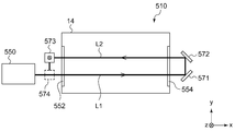
- FIG. 8 is a side view schematically showing a configuration of an ion implantation apparatus 510 according to a modification.
- the plurality of optical paths L1, L2, L3, L4, L5, and L6 through which the laser light passes are configured to extend in the horizontal direction.
- the first optical path L1, the third optical path L3, and the fifth optical path are configured such that the laser light travels in the first direction (the direction exiting from the paper surface of FIG. 8), and the second optical path L2, the fourth optical path L4, and the The six optical paths L6 are configured such that the laser light travels in a second direction opposite to the first direction (a direction entering the paper surface of FIG. 8).
- the plurality of optical paths L1, L3, and L5 in which the laser light travels in the first direction and the plurality of optical paths L2, L4, and L6 in which the laser light travels in the second direction are provided at positions shifted from each other in the vertical direction (y direction). Yes.
- this modification will be described focusing on differences from the above-described embodiment and modifications.
- FIG. 9 is a top view schematically showing the configuration of the ion implantation apparatus 510, and schematically shows the arrangement of the optical system when viewed in the direction of arrow C in FIG. In the figure, for the sake of easy understanding, the positions of the optical paths L1 to L6 are drawn so as not to overlap.
- the ion implantation apparatus 510 includes a laser irradiation apparatus 550, an entrance window 552, an exit window 554, a beam damper 556, and a plurality of mirrors 571 to 580.
- laser light from the laser irradiation device 550 travels in the first direction from the entrance window 552 to the exit window 554 in the odd-numbered optical paths L1, L3, and L5, and even-numbered optical paths L2, L4, and L6.
- the second direction from the exit window 554 to the entrance window 552 is advanced.
- the first mirror 571 directs the laser beam emitted from the emission window 554 toward the second mirror 572 along the first optical path L1.
- the second mirror 572 causes the laser light from the first mirror 571 to enter the emission window 554 along the second optical path L2.
- the third mirror 573 causes the laser light emitted from the incident window 552 to be directed to the fourth mirror 574 along the second optical path L2.
- the fourth mirror 574 causes the laser beam from the third mirror 573 to enter the incident window 552 along the third optical path L3.
- the fifth mirror 575 directs the laser light emitted from the emission window 554 along the fourth optical path L4 to the sixth mirror 576, and the sixth mirror 576 directs the laser light from the fifth mirror 575 to the fourth optical path L4.
- the seventh mirror 577 directs the laser light emitted from the incident window 552 along the fourth optical path L4 to the eighth mirror 578, and the eighth mirror 578 directs the laser light from the seventh mirror 577 to the fifth optical path L5.
- the ninth mirror 579 directs the laser light emitted from the emission window 554 along the fifth optical path L5 to the tenth mirror 580, and the tenth mirror 580 directs the laser light from the ninth mirror 579 to the sixth optical path L6.
- the light is incident on the exit window 554.
- Laser light emitted from the incident window 552 along the sixth optical path is absorbed by the beam damper 556.
- the laser beam is sequentially passed through the plurality of optical paths L1 to L6 by using one or more optical elements arranged at least partially different from the illustrated configuration.
- a reflective optical element such as a mirror may be used, or a transmissive optical element such as a lens or a prism may be used.
- the number of optical paths of the laser light that intersects the beam line device 14 is an example, and may be 5 or less, or 7 or more.
- one or more arbitrary optical elements may be appropriately arranged depending on the number of laser beam folding (that is, the number of optical paths).
- FIG. 10 is a cross-sectional view schematically showing the configuration of the ion implantation apparatus 510, which corresponds to the cross section along the line DD in FIG.
- the first optical path L1 and the second optical path L2 are arranged at positions shifted in the vertical direction (y direction).
- the first mirror 571 changes the direction of laser light traveling in the horizontal direction (first direction) along the first optical path L1 in the upward direction (+ y direction).
- the second mirror 572 is provided so as to change the direction of the laser light from the first mirror 571 in the horizontal direction (second direction) along the second optical path L2.
- the third mirror 573 changes the direction of laser light traveling in the horizontal direction (second direction) from the second mirror 572 toward the fourth mirror 574 downward ( ⁇ y direction). In this manner, the plurality of mirrors 571 to 580 realize a one-stroke spiral path from the laser irradiation device 550 to the beam damper 556.
- the plurality of optical paths L1, L3, and L5 along which the laser light travels in the first direction are straight lines extending from the downstream end of the AEF lower electrode 36b of the angular energy filter 34 toward the wafer W. Arranged to line up.
- the optical paths L1, L3, and L5 in the first direction in this way, laser beams are effectively applied to particles flying in the direction toward the wafer W among the particles generated in the AEF lower electrode 36b. can do.
- the laser beams are all irradiated in the same first direction in the plurality of optical paths L1, L3, and L5 in the first direction, the radiation pressure in the same direction can be applied to the particles. Thereby, it is possible to effectively prevent the particles generated at the AEF lower electrode 36b from attaching to the wafer W.
- the plurality of optical paths L2, L4, and L6 along which the laser light travels in the second direction are arranged on a straight line extending from the downstream end of the AEF upper electrode 36a of the angular energy filter 34 toward the wafer W. Be placed.
- the optical paths L2, L4, and L6 in the second direction in this way, the laser beam is effectively applied to the particles flying in the direction toward the wafer W among the particles generated in the AEF upper electrode 36a. be able to.
- the laser beams are all irradiated in the same second direction in the plurality of optical paths L2, L4, and L6 in the second direction, the radiation pressure in the same direction can be applied to the particles. This effectively prevents particles generated at the AEF upper electrode 36a from attaching to the wafer W.
- [rho is the density of the particle [g / cm 3]
- H V is the evaporation enthalpy of the particle [kJ / mol]
- V 0 is the speed of the particles towards the wafer [m / s]
- R is the particle diameter [Cm]
- w are the full spot width [cm] of the laser beam to be irradiated.
- the particle trajectory can be changed by the radiation pressure of the laser beam, and a radiation pressure sufficient to change the trajectory in a direction not hitting the wafer can be applied.
- c is the speed of light ( ⁇ 3 ⁇ 10 8 [m / s])
- ⁇ is a necessary displacement angle.
- the generation source of the particles is the angular energy filter 34
- the distance from the downstream end of the angular energy filter 34 to the wafer W is Z
- the present invention has been described with reference to the above-described embodiments.
- the present invention is not limited to the above-described embodiments, and the configurations of the embodiments are appropriately combined or replaced. Those are also included in the present invention. Further, based on the knowledge of those skilled in the art, it is possible to appropriately change the combination and processing order in each embodiment and to add various modifications such as various design changes to the embodiment. Added embodiments may also fall within the scope of the present invention.
- the configuration in which the ion beam transported by the beam line device is scanned in the x direction and irradiated onto the wafer is shown.
- the ion beam transported by the beamline device may not be scanned in the x direction.
- the ion beam transported by the beam line device may be a ribbon beam having a long beam diameter in the x direction.
- the configuration in which the implantation processing chamber is provided separately from the beam line device for transporting the ion beam is shown.
- the beam line device and the implantation processing chamber may be integrally configured.
- the portion that transports the ion beam and the portion that is subjected to the implantation process on the wafer may be collectively referred to as a “beam line device”.
- the present invention relates to an ion implantation apparatus.
Landscapes
- Chemical & Material Sciences (AREA)
- Analytical Chemistry (AREA)
- Physical Vapour Deposition (AREA)
Abstract
イオン注入装置(10)は、ウェハ(W)に向けてイオンビーム(B)を輸送するよう構成されるビームライン装置(14)と、ビームライン装置(14)により輸送されるイオンビーム(B)に向けてイオンビーム(B)の進行方向と交差する方向にレーザ光(L)を照射するよう構成されるレーザ照射装置(50)と、を備える。レーザ照射装置(50)は、ビームライン装置(14)内で発生してウェハ(W)に向かって飛ぶパーティクル(70)にレーザ光(L)を照射して、パーティクル(70)がウェハ(W)にそのまま付着するのを妨げる。
Description
本発明は、イオン注入装置に関する。
半導体製造工程では、導電性を変化させる目的、半導体ウェハの結晶構造を変化させる目的などのため、半導体ウェハにイオンを注入する工程(以下、「イオン注入工程」と称する場合がある)が標準的に実施されている。イオン注入工程で使用される装置は、イオン注入装置と呼ばれ、イオン源によってイオンを生成し、生成したイオンを加速してイオンビームを形成する機能と、そのイオンビームを真空処理室まで輸送し、処理室内のウェハにイオンビームを照射する機能を有する。
イオンビームが輸送される真空チャンバ内では、様々な要因によりパーティクルが生じることがある。真空チャンバ内で発生したパーティクルが浮遊してウェハの表面に付着すると、ウェハ表面のレジストパターンを損傷させたり、均一なイオン注入を妨げたりする場合がある。そうすると、イオン注入工程の歩留まりが低下してしまうかもしれない。
本発明のある態様の例示的な目的のひとつは、パーティクルの発生による生産性の低下を抑制する技術を提供することにある。
本発明のある態様のイオン注入装置は、ウェハに向けてイオンビームを輸送するよう構成されるビームライン装置と、ビームライン装置により輸送されるイオンビームに向けてイオンビームの進行方向と交差する方向にレーザ光を照射するよう構成されるレーザ照射装置と、を備える。レーザ照射装置は、ビームライン装置内で発生してウェハに向かって飛ぶパーティクルにレーザ光を照射して、パーティクルがウェハにそのまま付着するのを妨げる。
本発明の別の態様もまた、イオン注入装置である。この装置は、前段ビーム経路を通って入射するイオンビームに電界を作用させ、ウェハに向かう後段ビーム経路を通って出射させるようにイオンビームを偏向させるビーム偏向装置と、ビーム偏向装置の下流側であって、後段ビーム経路を挟んで対向するそれぞれの位置に設けられる入射窓および出射窓と、入射窓を通じて後段ビーム経路中のイオンビームにレーザ光を照射し、照射後のレーザ光を出射窓から出射させるように構成されるレーザ照射装置と、を備える。
なお、以上の構成要素の任意の組み合わせや本発明の構成要素や表現を、方法、装置、システムなどの間で相互に置換したものもまた、本発明の態様として有効である。
本発明によれば、ウェハへのパーティクルの付着を防いでイオン注入工程の生産性を向上させることができる。
以下、図面を参照しながら、本発明を実施するための形態について詳細に説明する。なお、図面の説明において同一の要素には同一の符号を付し、重複する説明を適宜省略する。また、以下に述べる構成は例示であり、本発明の範囲を何ら限定するものではない。
実施の形態の説明する前に、本発明の概要を述べる。本実施の形態に係るイオン注入装置は、ウェハに向けてイオンビームを輸送するよう構成されるビームライン装置を備える。イオン注入の対象となるウェハの表面には、ウェハの所望の位置に選択的にイオン注入を施すためのレジストマスク等が一般に設けられる。レジストマスクは、イオンビームの照射によってその一部が飛散し、レジストアウトガスといわれるガス分子を生じさせる。
ビームライン装置には電界の作用によりイオンビームを偏向させる偏向手段などの電極部が設けられている。上述のレジストアウトガスの一部は、電界の作用等によって電極部に付着して堆積し、かたまりとなった堆積物を形成しうる。堆積物の一部は、電極部で発生する放電等により飛散し、パーティクルとしてビームライン装置内を浮遊する。このパーティクルがウェハの表面に付着すると、ウェハ表面のレジストパターンを損傷させたり、イオンビームの照射を遮ることで均一なイオン注入を妨げたりするおそれが生じる。そうすると、イオン注入工程の製造歩留まりが低下し、生産性に影響を及ぼしうる。
そこで、本実施の形態に係るイオン注入装置は、ビームライン装置により輸送されるイオンビームに向けてイオンビームの進行方向と交差する方向にレーザ光を照射するよう構成されるレーザ照射装置を備える。レーザ照射装置は、ビームライン装置内で発生してウェハに向かって飛ぶパーティクルにレーザ光を照射して、パーティクルがウェハにそのまま付着するのを妨げる。より具体的には、レーザ光の照射によりパーティクルに放射圧を与えてパーティクルの軌道を変化させ、パーティクルがウェハに向かわないようにする。または、レーザ光の照射によりパーティクルを加熱して分解または蒸散させ、ウェハに向かうパーティクルの粒径を小さくする。これにより、パーティクルの付着による歩留まり低下を抑制して、イオン注入工程の生産性を向上させる。
図1は、実施の形態に係るイオン注入装置10を概略的に示す図である。図1(a)は、イオン注入装置10の概略構成を示す上面図であり、図1(b)は、イオン注入装置10の概略構成を示す側面図である。
イオン注入装置10は、被処理物Wの表面にイオン注入処理をするよう構成されている。被処理物Wは、例えば基板であり、例えば半導体ウエハである。よって以下では説明の便宜のため被処理物Wを基板Wと呼ぶことがあるが、これは注入処理の対象を特定の物体に限定することを意図していない。
イオン注入装置10は、ビームの往復走査およびウェハWの往復運動によりウェハWの全体にわたってイオンビームBを照射するよう構成されている。イオンビームBを対象物Wに対し走査する場合において、ビームの往復走査は矢印Xの方向に行われ、ウェハWの往復運動は矢印Yの方向に行われる。
イオン注入装置10は、イオン源12と、ビームライン装置14と、注入処理室16と、を備える。イオン源12は、イオンビームBをビームライン装置14に与えるよう構成されている。ビームライン装置14は、イオン源12から注入処理室16へとイオンを輸送するよう構成されている。また、イオン注入装置10は、イオン源12、ビームライン装置14、及び注入処理室16に所望の真空環境を提供するための真空排気系(図示せず)を備える。
ビームライン装置14は、例えば、上流から順に、質量分析部18、ビーム整形部20、ビーム計測部22、ビーム走査器24、平行化レンズ30又はビーム平行化装置、及び、角度エネルギーフィルター(AEF;Angular Energy Filter)34を備える。なお、ビームライン装置14の上流とは、イオン源12に近い側を指し、下流とは注入処理室16(またはビームストッパ38)に近い側を指す。
質量分析部18は、イオン源12の下流に設けられており、イオン源12から引き出されたイオンビームBから必要なイオン種を質量分析により選択するよう構成されている。ビーム整形部20は、四重極収束装置(Qレンズ)などの収束レンズを備えており、イオンビームBを所望の断面形状に整形するよう構成されている。
ビーム計測部22は、ビームライン上に出し入れ可能に配置され、イオンビームの強度ないし電流を計測する。ビーム計測部22は、ビーム電流を計測するファラデーカップ22bと、ファラデーカップ22bを上下に移動させる駆動部22aを有する。図1(b)の破線で示すように、ビームライン上にファラデーカップ22bを配置した場合、イオンビームBはファラデーカップ22bにより遮断される。一方、図1(b)の実線で示すように、ファラデーカップ22bをビームライン上から外した場合、イオンビームBの遮断が解除される。したがって、ビーム計測部22は、イオンビームBの遮断手段としても機能する。
ビーム走査器24は、ビームの往復走査を提供するよう構成されており、整形されたイオンビームBをx方向に走査する偏向手段である。ビーム走査器24は、x方向に対向して設けられる走査電極対26を有する。走査電極対26は可変電圧電源(図示せず)に接続されており、走査電極対26に印加される電圧を周期的に変化させることにより、電極間に生じる電界を変化させてイオンビームBを偏向させる。こうして、イオンビームBは、x方向の走査範囲にわたって走査される。なお、図1(a)において矢印Xによりビームの走査方向及び走査範囲を例示し、走査範囲でのイオンビームBの複数の軌跡を一点鎖線で示している。なお、ビーム走査器24は、磁界を印加することによりイオンビームを走査する磁界式の偏向手段であってもよい。
ビーム走査器24は、走査イオンビームBが通過する開口部24aの外側に設けられるビームダンパ28を有する。ビームダンパ28は、ビームスキャンされるx方向の走査範囲を超えてイオンビームBを偏向させた場合に、イオンビームBが衝突する箇所に設けられる。ビームダンパ28は、イオンビームの衝突によるスパッタが生じにくいグラファイト(C)などの材料で構成される。なお、図1(a)において破線の矢印B’によりビームダンパ28に衝突する場合のイオンビームの軌跡を示している。
イオンビームBがビームダンパ28に衝突するようにビーム走査器24を動作させた場合、イオンビームBはビームラインから外れて、途中で遮断されることとなる。したがって、ビーム走査器24は、イオンビームBの遮断手段としても機能する。なお、イオンビームBが通常の走査範囲でスキャンされるようにビーム走査器24を動作させれば、つまり、イオンビームBが開口部24aから出射されるようにビーム走査器24を動作させれば、イオンビームBの遮断が解除される。
平行化レンズ30は、走査されたイオンビームBの進行方向を平行にするよう構成されている。平行化レンズ30は、中央部にイオンビームの通過スリットが設けられた円弧形状の複数の平行化レンズ電極32を有する。平行化レンズ電極32は、高圧電源(図示せず)に接続されており、電圧印加により生じる電界をイオンビームBに作用させて、イオンビームBの進行方向を平行に整える。
角度エネルギーフィルタ(AEF)34は、イオンビームBのエネルギーを分析し必要なエネルギーのイオンを下方に偏向して注入処理室16に導くよう構成されている。したがって、角度エネルギーフィルタ34は、ビーム偏向装置として機能する。
角度エネルギーフィルタ34は、電界偏向用のAEF電極対36を有する。AEF電極対36は、高圧電源(図示せず)に接続される。図1(b)において、上側のAEF電極に正電圧、下側のAEF電極に負電圧を印加させることにより、イオンビームBを下方に偏向させる。なお、角度エネルギーフィルタ34は、磁界偏向用の磁石装置で構成されてもよく、電界偏向用のAEF電極対と磁石装置の組み合わせで構成されてもよい。
なお、本明細書において、角度エネルギーフィルタ34に入射するイオンビームが通る経路を「前段ビーム経路」ともいい、角度エネルギーフィルタ34から出射するイオンビームが通る経路を「後段ビーム経路」ともいう。前段ビーム経路を通るイオンビームの進行方向と、後段ビーム経路を通るイオンビームの進行方向は、AEF電極対36で発生する電界の作用によってy方向にずれており、その偏向角度θは約10~20度である。
このようにして、ビームライン装置14は、ウェハWに照射されるべきイオンビームBを注入処理室16に供給する。
注入処理室16には、ビームストッパ38、プラズマシャワー装置40、エネルギースリット42、往復運動装置44が設けられる。往復運動装置44は、1枚又は複数枚のウェハWを保持し、イオンビームBに対する相対移動(例えば、y方向)を必要に応じてウェハWに提供するよう構成される。図1(b)において、矢印YによりウェハWの往復運動を例示する。ビーム軌道上にウェハWが存在しない場合には、イオンビームBはビームストッパ38に入射する。
プラズマシャワー装置40は、イオンビームBのビーム電流量に応じてイオンビームとウェハWの前面に低エネルギー電子を供給し、イオン注入で生じるウェハW表面での正電荷のチャージアップを抑制する。
エネルギースリット42は、ビームスキャン方向(x方向)に横長のスリットで構成されるエネルギー制限スリット(EDS;Energy Defining Slit)である。エネルギースリット42は、ウェハに向けて後段ビーム経路中を進行するビームを部分的に遮蔽し、後段ビーム経路中のビームの中で所定軌道を有するビーム成分をウェハに向けて通過させる。これにより、所用以外のエネルギー値と価数を持つイオンビームの通過を制限し、角度エネルギーフィルタ34を通過した所用のエネルギー値と価数を持つイオンビームだけを分離する。したがって、エネルギースリット42は、角度エネルギーフィルタ34とともにウェハWに入射するイオンビームのエネルギー分析を行う。
イオン注入装置10は、レーザ照射装置50、入射窓52、出射窓54、レーザダンパ56、光検出器58をさらに備える。入射窓52および出射窓54は、注入処理室16を構成するチャンバの壁面の一部に設けられる。入射窓52および出射窓54は、角度エネルギーフィルタ34よりも下流側に設けられ、イオンビームBの軌道を挟んでx方向に対向する位置に設けられる。入射窓52および出射窓54は、レーザ照射装置50が出力するレーザ光の波長に対して透明な材質で構成される。
レーザ照射装置50は、高出力のレーザ光が出力可能なレーザ光源を含み、例えば、YAGレーザ、CO2レーザ、ファイバレーザ、半導体レーザなどのレーザ発振器を含む。レーザ照射装置50は、イオンビームBに向けてイオンビームの進行方向と交差する方向にレーザ光Lを照射するように配置される。レーザ照射装置50から出力されるレーザ光Lは、入射窓52を通じて注入処理室16の内部に導入され、出射窓54を通じて注入処理室16の外部に出射される。出射窓54から出射されるレーザ光Lは、レーザダンパ56に吸収される。したがって、レーザ照射装置50からのレーザ光Lは、イオンビームBの軌道に向けて水平方向(x方向)に照射される。
レーザ照射装置50は、ビームライン装置14または注入処理室16の内部で発生し、ウェハWに向かって飛ぶパーティクル70に向けてレーザ光Lを照射する。パーティクル70は、例えば、高電圧が印加されるAEF34にて発生し、イオンビームBの軌道に沿ってウェハWに向かう。レーザ照射装置50は、パーティクル70に対して水平方向(x方向)にレーザ光を照射することで、パーティクル70にx方向の放射圧を与える。その結果、パーティクル70にはx方向の運動量が付加され、パーティクル70が飛ぶ方向がx方向に変化する。レーザ光により与えられる放射圧が十分に大きければ、パーティクル70はウェハWに到達しない方向に向きを変えて飛んでいく。例えば、パーティクル70は、ウェハWの手前に位置するエネルギースリット42やプラズマシャワー装置40の内壁に向かって飛んでこれらに衝突する。レーザ照射装置50は、このようにしてパーティクル70の飛ぶ方向を変化させ、パーティクル70がウェハWの表面への付着を妨げる。
また、レーザ照射装置50は、レーザ光Lの照射によってパーティクル70にエネルギを付与し、パーティクル70を分解または蒸散させてもよい。例えば、パーティクル70を構成する物質の結合エネルギーを上回るようなエネルギーを付与できるパワーのレーザ光を照射することで、パーティクル70をより粒径の小さな複数のパーティクルに分解させたり、パーティクル70を蒸散させてガス分子化させたりしてもよい。レーザ照射装置50は、例えば、粒径が数十nm~数μm程度であるパーティクル70を分解または蒸散させることにより、粒径が数nm~数十nm以下となるようにしてもよい。粒径を小さくすることで、ウェハW表面へのパーティクルの付着による影響を低減できる。なおレーザ照射装置50は、レーザ光Lの照射によってパーティクル70を分解させるとともに、分解後に生じたパーティクルの軌道がウェハWに向かわないようにしてもよい。
光検出器58は、ビームライン装置14または注入処理室16の内部を浮遊するパーティクル70からの散乱光Sを検出するように配置される。光検出器58は、例えばレーザ照射装置50からレーザダンパ56に向かうレーザ光Lの光路の近傍であって、レーザ光Lの光路から外れた位置に設けられる。光検出器58は、例えば出射窓54を通じて出射される散乱光Sを検出するように配置される。なお変形例では、光検出器58が入射窓52を通じて出射される散乱光を検出できる位置に配置されてもよいし、ビームライン装置14や注入処理室16の内部に配置されてもよい。
制御装置60は、イオン注入装置10を構成する各機器の動作を制御する。制御装置60は、光検出器58の検出結果に応じて、ビーム計測部22やビーム走査器24などのビーム遮断手段を動作させてイオンビームBの照射を停止させる。制御装置60は、光検出器58によって検出される散乱光の強度が所定の閾値レベルを上回る場合や、所定の閾値レベルを上回る期間が基準時間を超える場合に、イオンビームBの照射を停止させる。イオンビームBの照射を停止させる条件は、イオン注入工程の歩留まりが大きく低下しうる程度に多くのパーティクルが検出される値として設定される。制御装置60は、イオンビームBの照射を停止させる場合に、レーザ照射装置50からのレーザ光Lの出力も同時に停止させてもよい。
以上の構成により、イオン注入装置10は、ウェハWにイオンビームBを照射するイオン注入処理中においてイオンビームBに向けてレーザ光Lを照射し、イオンビームBに沿ってウェハWに向かって飛ぶパーティクル70がウェハWにそのまま付着しないようにする。これにより、イオン注入処理中のウェハWの表面にパーティクル70が付着して製造歩留まりが低下する影響を低減することができる。特に、ビームライン装置14や注入処理室16の内部に形成される堆積物がそれほど多くなく、ウェハWに向かって飛ぶパーティクル数が比較的少ない状況である場合に、パーティクルの付着を防ぐことで歩留まりの低下を抑えることができる。
また、イオン注入装置10は、イオンビームBに向けて照射するレーザ光の散乱光を検出することで、ウェハWに向かって飛ぶパーティクルの状況を監視する。これにより、ウェハWに向かうパーティクル数が多くなる状況を検知し、ビームライン装置14や注入処理室16の内部の清掃や部品交換といったメンテナンス対応を適切なタイミングで取れるようにする。また、ウェハWに向かうパーティクル数が多くなって適切なイオン注入処理ができなくなるおそれが生じる場合に、イオンビームBの照射を停止させることによって、使用するウェハWが無駄になってしまうのを防ぐことができる。これにより、イオン注入装置10の製造歩留まりを改善させることができる。
また、イオン注入装置10は、レーザ照射装置50をビームライン装置14および注入処理室16の外に配置する構成としている。このため、レーザ照射装置50を真空環境に置く必要がなくなるため、レーザ照射装置50の扱いを容易にすることができる。また、レーザ照射装置50からの高出力のレーザ光Lを出射窓54を通じて注入処理室16の外に出射させる構成としているため、レーザ光がビームライン装置14または注入処理室16内で反射して意図しない箇所に当たってしまうことを防ぐことができる。これにより、イオン注入装置10の構成機器にレーザ光が照射されて損傷を受ける等の影響を抑えることができる。
(変形例1)
図2は、変形例に係るイオン注入装置110の構成を概略的に示す上面図である。本変形例は、入射窓152および出射窓154がビームライン装置14を構成するチャンバの壁面に設けられ、レーザ照射装置150からのレーザ光Lが角度エネルギーフィルタ34のすぐ下流の位置に照射される点で上述の実施の形態と相違する。以下、本変形例について、上述の実施の形態との相違点を中心に説明する。
図2は、変形例に係るイオン注入装置110の構成を概略的に示す上面図である。本変形例は、入射窓152および出射窓154がビームライン装置14を構成するチャンバの壁面に設けられ、レーザ照射装置150からのレーザ光Lが角度エネルギーフィルタ34のすぐ下流の位置に照射される点で上述の実施の形態と相違する。以下、本変形例について、上述の実施の形態との相違点を中心に説明する。
入射窓152および出射窓154は、角度エネルギーフィルタ34のすぐ下流の位置において、後段ビーム経路を挟んで水平方向(x方向)に対向して配置される。レーザ照射装置150からのレーザ光Lは、入射窓152を通じて後段ビーム経路に水平方向に照射される。後段ビーム経路を通過したレーザ光Lは、出射窓154を通じてビームライン装置14の外に出力され、レーザダンパ156により吸収される。パーティクルからの散乱光Sは、出射窓154を通じて光検出器158により検出される。
本変形例においても、上述の実施の形態と同様の効果を得ることができる。また、本変形例によれば、パーティクルの発生源となりうる角度エネルギーフィルタ34のより近い位置でレーザ光Lを照射するため、上述の実施の形態よりもレーザ照射によるパーティクルの変位量が小さくて済む。レーザ照射位置からウェハWまでの距離が上述の実施の形態より長く、パーティクルの飛ぶ方向の角度を変えるために必要な変位量が小さくて済むからである。したがって、本変形例によれば、上述の実施の形態よりも少ないパワーでパーティクルの飛ぶ方向を好適に変化させることができる。
(変形例2)
図3は、変形例に係るイオン注入装置210の構成を概略的に示す側面図である。本変形例は、イオンビームBに向けてレーザ照射装置250からのレーザ光Lが上下方向(y方向)に照射される点で上述の実施の形態および変形例と相違する。以下、本変形例について、上述の実施の形態および変形例との相違点を中心に説明する。
図3は、変形例に係るイオン注入装置210の構成を概略的に示す側面図である。本変形例は、イオンビームBに向けてレーザ照射装置250からのレーザ光Lが上下方向(y方向)に照射される点で上述の実施の形態および変形例と相違する。以下、本変形例について、上述の実施の形態および変形例との相違点を中心に説明する。
入射窓252および出射窓254は、角度エネルギーフィルタ34の下流の位置において、後段ビーム経路を挟んで上下方向(y方向)に対向して配置される。入射窓252は、鉛直方向の上側に配置され、出射窓254は、鉛直方向の下側に配置される。レーザ照射装置250は、レーザ光Lを鉛直方向下方に向けて出力し、後段ビーム経路に沿って進むパーティクルに対して下向きの放射圧を与える。言いかえれば、レーザ照射装置250は、角度エネルギーフィルタ34によるイオンビームBの偏向方向と同じ向きの放射圧をパーティクルに対して与えるように構成される。
図4は、イオン注入装置210の構成を概略的に示す断面図であり、図3のA-A線断面を示す。レーザ照射装置250は、イオンビームBの走査方向にわたってレーザ光Lを照射できるように構成される。レーザ照射装置250は、例えば、レーザ光Lの出射位置をx方向にスキャンできるようなレーザ走査機構を有する。このレーザ走査機構は、例えば、ポリゴンミラーとf-θレンズにより構成される。
なお、レーザ照射装置250がファイバーレーザを備える場合には、ファイバレーザの出射口をx方向にスキャンすることにより、x方向にわたってレーザ光を照射できるように構成してもよい。また、レーザ照射装置250は、x方向に並べて配置される複数のレーザ光源を備えることにより、x方向にわたって複数のレーザ光Lを照射できるように構成されてもよい。
本変形例によれば、レーザ照射装置250が角度エネルギーフィルタ34の偏向方向と同じ向きの放射圧をパーティクルに対して与えるため、上述の実施の形態よりもレーザ照射によるパーティクルの変位量が小さくて済む。レーザ照射位置の下流にはy方向の開口幅が制限されたエネルギースリット42やプラズマシャワー装置40が設けられるため、より小さな変位量であってもエネルギースリット42やプラズマシャワー装置40に衝突するようにパーティクルの飛ぶ方向を変えられるからである。また、レーザ照射によるパーティクルの変位方向を下向きとすることで、パーティクルがウェハWに到達するまでの間にパーティクルに作用する重力を利用することもできる。したがって、本変形例によれば、より少ないパワーでパーティクルの飛ぶ方向を好適に変化させることができる。
(変形例3)
図5は、変形例に係るイオン注入装置310の構成を概略的に示す上面図である。本変形例は、レーザ照射装置150からのレーザ光が折り返され、イオンビームBの進行方向と交差する複数の光路L1,L2,L3に沿ってレーザ光が照射されるように構成される点で上述の実施の形態および変形例と相違する。以下、本変形例について、上述の実施の形態および変形例との相違点を中心に説明する。
図5は、変形例に係るイオン注入装置310の構成を概略的に示す上面図である。本変形例は、レーザ照射装置150からのレーザ光が折り返され、イオンビームBの進行方向と交差する複数の光路L1,L2,L3に沿ってレーザ光が照射されるように構成される点で上述の実施の形態および変形例と相違する。以下、本変形例について、上述の実施の形態および変形例との相違点を中心に説明する。
入射窓152および出射窓154は、角度エネルギーフィルタ34のすぐ下流の位置において、後段ビーム経路を挟んで水平方向(x方向)に対向して配置される。複数の光路L1~L3は、入射窓152および出射窓154の双方を通過するように設けられ、それぞれ水平方向に延びるように設けられる。第1光路L1は、角度エネルギーフィルタ34に近い上流側に設けられ、第3光路L3は、エネルギースリット42に近い下流側に設けられ、第2光路L2は、第1光路L1と第3光路L3の間に設けられている。複数の光路L1~L3は、例えば、互いに平行となるように設けられる。
レーザ照射装置150は、入射窓152に向けてレーザ光を出力する。レーザ照射装置150から出力されるレーザ光は、複数のミラー371,372,373,374により向きが変えられ、複数の光路L1~L3を順に通過する。複数のミラー371~374は、ビームライン装置14の外側に配置されている。第1ミラー371は、第1光路L1に沿って出射窓154から出射するレーザ光を反射させ、レーザ光が第2ミラー372に向かうようにする。第2ミラー372は、第1ミラー371からのレーザ光を反射させ、レーザ光が第2光路L2に沿って出射窓154に入射するようにする。第3ミラー373は、第2光路L2に沿って入射窓152から出射するレーザ光を反射させ、レーザ光が第4ミラー374に向かうようにする。第4ミラー374は、第3ミラー373からのレーザ光を反射させ、レーザ光が第3光路L3に沿って入射窓152に入射するようにする。
レーザ照射装置150からのレーザ光は、上述の光学配置により複数の光路L1~L3を順に通過する一筆書きの経路を辿ることとなる。図示されるように、第1光路L1および第3光路L3では、入射窓152から出射窓154に向かう第1方向にレーザ光が照射される。一方、第2光路L2では、出射窓154から入射窓152に向かう第2方向(第1方向と反対方向)にレーザ光が照射される。
なお、別の変形例においては、図示される構成とは少なくとも部分的に異なるように配置される一以上の光学素子を用いて、レーザ光が複数の光路L1~L3を順に通過するようにしてもよい。光学素子として、ミラーのような反射型の光学素子を用いてもよいし、レンズやプリズムといった透過型の光学素子を用いてもよい。また、レーザ光が通過する複数の光路が水平方向ではなく垂直方向に延びるように構成されてもよい。ビームライン装置14と交差するレーザ光の光路数は二つであってもよいし、四つ以上であってもよい。レーザ光の折り返し数(つまり、光路数)に応じて一以上の任意の光学素子が適宜配置されてもよいことは、当業者であれば理解されることである。また、レーザ光が通過する光路を規定する一以上の光学素子は、その少なくとも一部がビームライン装置14の内部に設けられていてもよい。その他、互いに対向する二枚の平面鏡の間でレーザ光を繰り返し反射させることにようにしてビームライン装置14と交差する複数の光路を構成してもよい。
第3光路L3に沿って進むレーザ光は、出射窓154から出射して計測装置356に入射する。計測装置356は、出射窓154から出力されるレーザ光の光強度や強度分布を計測する。計測装置356は、例えば、光強度の計測が可能なパワーメータであってもよいし、光強度分布の計測が可能なビームプロファイラであってもよい。計測装置356は、レーザ光の強度ないし強度分布を計測することにより、例えば、光源または光学系に異常が発生していないかを検知する。計測装置356は、計測したレーザ光に関する情報を制御装置60に送信する。
入射窓152の内側には、入射窓152の内面152aを被覆する入射窓カバー362が設けられる。同様にして出射窓154の内側には、出射窓154の内面154aを被覆する出射窓カバー364が設けられる。入射窓カバー362および出射窓カバー364は、レーザ照射装置150からのレーザ光を透過する材料で構成され、例えば、レーザ光の波長に対して透明な光学ガラスや樹脂フィルムなどで構成される。入射窓カバー362および出射窓カバー364の表面には、レーザ光の反射を抑制するための誘電体多層膜フィルタなどが設けられてもよい。入射窓カバー362および出射窓カバー364は、イオン注入装置310の使用に伴って入射窓152および出射窓154の内面152a,154aが汚れてしまうことを防ぐ。
入射窓カバー362および出射窓カバー364は、冷却装置366と熱的に接続されている。冷却装置366は、レーザ光の照射により加熱されうる入射窓カバー362および出射窓カバー364を冷却し、これら窓カバーの昇温を抑制する。冷却装置366は、入射窓カバー362および出射窓カバー364だけでなく、入射窓152および出射窓154と熱的に接続され、入射窓152および出射窓154を同時に冷却するように構成されてもよい。
図6は、イオン注入装置310の構成を概略的に示す断面図であり、図5のA-A線断面を示す。ビームライン装置14の内部には、入射窓カバー交換機構382および出射窓カバー交換機構384が設けられている。入射窓カバー交換機構382は、複数の交換用の入射窓カバー362bを保持し、入射窓152を被覆している入射窓カバー362aを別の入射窓カバー362bと交換するように構成されている。また、入射窓カバー交換機構382は、交換した後の使用済の入射窓カバー362aを一時的に保持するように構成されてもよい。これにより、イオン注入装置310の使用により入射窓カバー362aが汚れ、ビームライン装置14の内部に照射されるレーザ光の強度の低下を抑制する。
入射窓カバー交換機構382は、ビームライン装置14の内部空間が真空状態に維持されている状態で、入射窓カバー362の交換ができるように構成されてもよい。これにより、ビームライン装置14を大気開放することなく入射窓カバー362の交換をすることができ、大気開放に伴うメンテナンス工数増大および装置の稼働率低下を抑えることができる。
出射窓カバー交換機構384は、入射窓カバー交換機構382と同様に構成されている。出射窓カバー交換機構384は、複数の出射窓カバー364bを保持し、出射窓154を被覆している出射窓カバー364aを別の出射窓カバー364bと交換するように構成されている。出射窓カバー交換機構384は、イオン注入装置310の使用により出射窓カバー364aが汚れ、ビームライン装置14の内部に照射されるレーザ光の強度の低下を抑制する。
なお、さらなる変形例においては、入射窓カバー362および出射窓カバー364が複数のカバー部材の積層体で構成されてもよい。この積層体は、複数枚の透明な樹脂フィルムが接着剤などで仮止めされており、一枚ずつ樹脂フィルムを剥がしていくことにより積層体の表面が汚れていない状態に更新できるように構成されてもよい。この場合、入射窓カバー交換機構382および出射窓カバー交換機構384は、積層体を構成する複数枚の樹脂フィルムを一枚ずつ剥がすことができるように構成されてもよい。
別の変形例においては、入射窓カバー362および出射窓カバー364がローラに巻き取られた連続的なシートの一部により構成されてもよい。この場合、入射窓カバー交換機構382および出射窓カバー交換機構384は、窓カバーとなるシートを送り出すための送出ローラと、送り出されたシートを巻き取るための巻取ローラとを備えてもよい。このとき、送出ローラと巻取ローラの間に張られたシートの一部が窓カバーとして機能し、ローラを作動させてローラ間に張られたシートを更新することにより窓カバーの交換が実現されてもよい。つまり、使用中に汚れたシートの一部を巻取ローラで巻き取り、汚れていないシートの新しい一部を送出ローラから送り出すことにより窓カバーが交換されてもよい。
ビームライン装置14の上方には、レーザ照射装置150からのレーザ光が照射される領域を撮像するための光検出器358が設けられる。ビームライン装置14の壁面には、光検出器358による撮像を可能とするための撮像用窓376が設けられる。光検出器358は、CCDやCMOSセンサなどの撮像部358aと、撮像画像を用いてパーティクルの大きさ、数量、速度および進行方向などを解析する解析部358bとを有する。解析部358bは、例えば、撮像部358aが連続して撮像する複数の撮像画像を比較することによりパーティクルの速度や進行方向に関する情報を算出する。解析部358bは、撮像部358aの撮像画像を統計的に処理することにより、パーティクルの数量、大きさ、または、大きさの分布に関する情報を算出してもよい。このようにして、光検出器358は、ビームライン装置14の内部を飛来するパーティクルの状態をモニタリングする。光検出器358が算出した情報は、制御装置60に送られる。
制御装置60は、計測装置356や光検出器358からの情報に基づいて、イオン注入装置310の動作を制御する。制御装置60は、光検出器358からの情報に基づき、レーザ照射によりウェハWへのパーティクルの付着を好適に防ぐことができないと判定される場合にイオンビームBの照射を停止させてもよい。制御装置60は、パーティクルの大きさ、速度および進行方向に基づいて、そのパーティクルがウェハWに付着するか否かや、レーザ照射によりウェハWへのパーティクルの付着が回避できるか否かを判定してもよい。制御装置60は、例えば、光検出器358により検出されたパーティクルの数量が所定の基準値を超える場合や、所定の基準値を超える回数が所定値以上となった場合に、イオンビームBの照射を停止させてもよい。また、検出されたパーティクルの速度が所定値以上であるために、レーザ照射によるパーティクルの分解または変位が不十分であると判定される場合にイオンビームBの照射を停止させてもよい。
制御装置60は、計測装置356からの情報に基づいて、入射窓152および出射窓154の汚れ具合を判定してもよい。例えば、計測装置356にて計測されるレーザ光の強度が所定の閾値レベルを下回る場合や、所定の閾値レベルを下回る期間が基準時間を超える場合に、入射窓152および出射窓154が汚れていると判定し、入射窓カバー交換機構382および出射窓カバー交換機構384に入射窓カバー362および出射窓カバー364を交換させてもよい。制御装置60は、入射窓152および出射窓154が汚れていると判定される場合であって、前回の窓カバー交換からの経過時間が所定値以下であるような場合に、光学系に何らかの異常が発生していると判断して、レーザ照射装置150からのレーザ光の照射を停止させてもよい。
本変形例によれば、イオンビームBのビーム軌道と交差する複数の光路L1~L3に沿ってレーザ光を照射することで、ウェハWに向かって飛ぶパーティクルにレーザ光が照射される確率を高めることができる。また、パーティクルが複数の光路L1~L3と交差するように進む場合には、一つのパーティクルに対してより多くの分解エネルギーを与えることができる。これにより、ウェハWに付着しようとするパーティクルを低減させる効果を高めることができる。
本変形例によれば、レーザ光を通過させる入射窓152および出射窓154に窓カバーを設けることで、入射窓152および出射窓154が直接汚れてしまうことを防ぐことができる。ビームライン装置14は、内部が高真空に保たれるように構成されているため、その隔壁の一部を構成する入射窓152および出射窓154を交換することは容易ではないかもしれない。そのため、入射窓152および出射窓154の内面152a,154bが汚れてしまうと、そのメンテナンスにより多くの手間が生じてしまう。一方、本変形例によれば、交換可能な窓カバーを取り付けることにより、汚れによる入射窓152および出射窓154の交換をしなくて済むようにできる。また、内部に窓カバーを交換する機構を設けることで、一定期間であればビームライン装置14を大気開放することなく窓カバーの交換を実現できる。これにより、窓カバーの交換に伴うメンテナンス工数を削減し、レーザ照射によるパーティクルの除去効果を長い期間にわたって維持できる。
本変形例によれば、計測装置356や光検出器358からの情報を用いることで、レーザ照射装置150を含む光学系の異常や、ウェハWに向かうパーティクルに関する異常を検知できる。特に、光検出器358を用いてパーティクルの数量や速度に関する情報を取得し、ウェハWにパーティクルが付着するか否かを判定することにより、ウェハWへのパーティクルの影響の有無をイオン注入工程の実行中に検知できる。例えば、ウェハWへのパーティクルの影響が問題となる場合には、イオン注入処理の途中で工程を中止することもできる。これにより、無駄な注入処理が継続して実行されることを防ぎ、注入工程の生産性を高めることができる。
(変形例4)
図7は、変形例に係るイオン注入装置410の構成を概略的に示す上面図である。イオン注入装置410は、複数の光源451a,451b,451cを含むレーザ照射装置450を備える点で上述の実施の形態および変形例と相違する。複数の光源451a~451cは、例えば、イオンビームBの進行方向に沿って並べられている。第1光源451aは、第1光路L1に沿って進むレーザ光を出力し、第2光源451bは、第2光路L2に沿って進むレーザ光を出力し、第3光源451cは、第3光路L3に沿って進むレーザ光りを出力する。複数の光源451a~451cのそれぞれから出力されるレーザ光は、入射窓152を通じてビームライン装置14の内部に照射され、出射窓154を通じてビームライン装置14の外部に出射される。出射窓154から出射されるレーザ光のそれぞれは、レーザダンパ156に吸収される。
図7は、変形例に係るイオン注入装置410の構成を概略的に示す上面図である。イオン注入装置410は、複数の光源451a,451b,451cを含むレーザ照射装置450を備える点で上述の実施の形態および変形例と相違する。複数の光源451a~451cは、例えば、イオンビームBの進行方向に沿って並べられている。第1光源451aは、第1光路L1に沿って進むレーザ光を出力し、第2光源451bは、第2光路L2に沿って進むレーザ光を出力し、第3光源451cは、第3光路L3に沿って進むレーザ光りを出力する。複数の光源451a~451cのそれぞれから出力されるレーザ光は、入射窓152を通じてビームライン装置14の内部に照射され、出射窓154を通じてビームライン装置14の外部に出射される。出射窓154から出射されるレーザ光のそれぞれは、レーザダンパ156に吸収される。
本変形例によれば、複数の光源451a~451cを用いることで、レーザ光の光路を多段化してウェハWに向かって飛ぶパーティクルにレーザ光が照射される確率を高めることができる。また、各光路L1~L3においてレーザ光が同一方向(入射窓152から出射窓154に向かう方向)に照射されるため、パーティクルが複数の光路L1~L3と交差するように進む場合に、同じパーティクルに対して同じ方向の放射圧を与えることができる。これにより、光路が一つだけの場合や複数の光路間において異なる方向(例えば、逆方向)にレーザが照射される場合と比べ、パーティクルに対してより大きい変位量を与えることができ、ウェハWに付着しようとするパーティクルを低減させる効果を高めることができる。
なお、さらなる変形例では、複数の光路L1~L3がイオンビームの軌道方向に並べられるのではなく、イオンビームの軌道方向と交差または直交する方向に並べられてもよい。例えば、複数の光路L1~L3が垂直方向(y方向)に並べられるようにしてもよいし、水平方向(x方向)に並べられるようにしてもよい。その他、複数の光源を配置する代わりに上述の変形例3と同様に複数のミラーを配置することにより、y方向に延びる複数の光路を実現してもよい。この場合、各光路におけるレーザ光の進行方向は同じであってもよいし、異なっていてもよい(つまり、反対方向であってもよい)。後者の場合、レーザ光がジグザグ状に進んでもよい。また、複数の光路が広範囲にわたって高密度で配列されるように、反射ミラーを連続的に並べて配置してもよいし、連続的に構成される長い反射ミラーを配置してもよい。
(変形例5)
図8は、変形例に係るイオン注入装置510の構成を概略的に示す側面図である。本変形例では、レーザ光が通過する複数の光路L1,L2,L3,L4,L5,L6が水平方向に延びるように構成される。また、第1光路L1、第3光路L3および第5光路は、レーザ光が第1方向(図8の紙面から出る方向)に進むように構成され、第2光路L2、第4光路L4および第6光路L6は、レーザ光が第1方向と反対の第2方向(図8の紙面に入る方向)に進むように構成される。レーザ光が第1方向に進む複数の光路L1,L3,L5とレーザ光が第2方向に進む複数の光路L2,L4,L6は、互いに垂直方向(y方向)にずれた位置に設けられている。以下、本変形例について、上述の実施の形態および変形例との相違点を中心に述べる。
図8は、変形例に係るイオン注入装置510の構成を概略的に示す側面図である。本変形例では、レーザ光が通過する複数の光路L1,L2,L3,L4,L5,L6が水平方向に延びるように構成される。また、第1光路L1、第3光路L3および第5光路は、レーザ光が第1方向(図8の紙面から出る方向)に進むように構成され、第2光路L2、第4光路L4および第6光路L6は、レーザ光が第1方向と反対の第2方向(図8の紙面に入る方向)に進むように構成される。レーザ光が第1方向に進む複数の光路L1,L3,L5とレーザ光が第2方向に進む複数の光路L2,L4,L6は、互いに垂直方向(y方向)にずれた位置に設けられている。以下、本変形例について、上述の実施の形態および変形例との相違点を中心に述べる。
図9は、イオン注入装置510の構成を模式的に示す上面図であり、図8の矢印Cの向きに見たときの光学系の配置を模式的に示す。本図では、説明を分かりやすくする目的で、複数の光路L1~L6の位置が重ならないように描いている。イオン注入装置510は、レーザ照射装置550、入射窓552、出射窓554、ビームダンパ556、複数のミラー571~580を備える。レーザ照射装置550からのレーザ光は、図示されるように、奇数番目の光路L1,L3,L5において入射窓552から出射窓554に向かう第1方向に進み、偶数番目の光路L2,L4,L6において出射窓554から入射窓552に向かう第2方向に進む。
第1ミラー571は、第1光路L1に沿って出射窓554から出射するレーザ光を第2ミラー572に向けさせる。第2ミラー572は、第1ミラー571からのレーザ光を第2光路L2に沿って出射窓554に入射させる。第3ミラー573は、第2光路L2に沿って入射窓552から出射するレーザ光を第4ミラー574に向けさせる。第4ミラー574は、第3ミラー573からのレーザ光を第3光路L3に沿って入射窓552に入射させる。第5ミラー575は、第4光路L4に沿って出射窓554から出射するレーザ光を第6ミラー576に向けさせ、第6ミラー576は、第5ミラー575からのレーザ光を第4光路L4に沿って出射窓554に入射させる。第7ミラー577は、第4光路L4に沿って入射窓552から出射するレーザ光を第8ミラー578に向けさせ、第8ミラー578は、第7ミラー577からのレーザ光を第5光路L5に沿って入射窓552に入射させる。第9ミラー579は、第5光路L5に沿って出射窓554から出射するレーザ光を第10ミラー580に向けさせ、第10ミラー580は、第9ミラー579からのレーザ光を第6光路L6に沿って出射窓554に入射させる。第6光路に沿って入射窓552から出射するレーザ光は、ビームダンパ556に吸収される。
なお、別の変形例においては、図示される構成とは少なくとも部分的に異なるように配置される一以上の光学素子を用いて、レーザ光が複数の光路L1~L6を順に通過するようにしてもよい。光学素子として、ミラーのような反射型の光学素子を用いてもよいし、レンズやプリズムといった透過型の光学素子を用いてもよい。ビームライン装置14と交差するレーザ光の光路数は例示であり、5以下であってもよいし、7以上であってもよい。レーザ光の折り返し数(つまり、光路数)に応じて一以上の任意の光学素子が適宜配置されてもよいことは、当業者であれば理解されることである。
図10は、イオン注入装置510の構成を概略的に示す断面図であり、図8のD-D線断面に対応する。図示されるように第1光路L1と第2光路L2は、垂直方向(y方向)にずれた位置に配置されている。このような光路配置を実現するため、第1ミラー571は、第1光路L1に沿って水平方向(第1方向)に進むレーザ光の向きを上方向(+y方向)に変化させる。また、第2ミラー572は、第1ミラー571からのレーザ光の向きを第2光路L2に沿った水平方向(第2方向)に変化させるように設けられる。第3ミラー573は、第2ミラー572から水平方向(第2方向)に進むレーザ光の向きを第4ミラー574に向けて下方向(-y方向)に変化させる。このようにして、複数のミラー571~580は、レーザ照射装置550からビームダンパ556までの一筆書きの螺旋状の経路が実現されるようにする。
図8に示されるように、第1方向にレーザ光が進む複数の光路L1,L3,L5は、角度エネルギーフィルタ34のAEF下側電極36bの下流側端部からウェハWに向けて延ばした直線上に並ぶように配置される。第1方向の光路L1,L3,L5をこのように配置することにより、AEF下側電極36bにて生じたパーティクルのうち、ウェハWに向かう方向に飛ぶパーティクルに対して効果的にレーザ光を照射することができる。また、第1方向の複数の光路L1,L3,L5においてレーザ光が全て同じ第1方向に照射されているため、パーティクルに対して同じ方向の放射圧を与えることができる。これにより、AEF下側電極36bにて生じたパーティクルがウェハWに付着しようとするのを効果的に妨げることができる。
同様にして、第2方向にレーザ光が進む複数の光路L2,L4,L6は、角度エネルギーフィルタ34のAEF上側電極36aの下流側端部からウェハWに向けて延ばした直線上に並ぶように配置される。第2方向の光路L2,L4,L6をこのように配置することにより、AEF上側電極36aにて生じたパーティクルのうち、ウェハWに向かう方向に飛ぶパーティクルに対して効果的にレーザ光を照射することができる。また、第2方向の複数の光路L2,L4,L6においてレーザ光が全て同じ第2方向に照射されているため、パーティクルに対して同じ方向の放射圧を与えることができる。これにより、AEF上側電極36aにて生じたパーティクルがウェハWに付着しようとするのを効果的に妨げることができる。
(レーザ光のパワー)
つづいて、パーティクルの分解および変位に必要なレーザの光強度(パワー)について述べる。パーティクルを分解または蒸散させるためには、レーザ照射によりパーティクルの蒸散に必要なエネルギーを付与できればよい。このようなレーザのパワー密度P1[W/cm2]は、P1=8ρHVV0R/3wと表すことができる。ここで、ρはパーティクルの密度[g/cm3]、HVは、パーティクルの蒸発エンタルピー[kJ/mol]、V0は、ウェハに向かうパーティクルの速度[m/s]、Rは、パーティクル径[cm]、wは、照射するレーザ光のスポット全幅[cm]である。上記式では、スポット幅wのレーザ光からエネルギーを受ける時間をΔt=w/V0とし、パーティクルに照射されるレーザ光の半分(50%)がパーティクルに吸収されるものと仮定している。
つづいて、パーティクルの分解および変位に必要なレーザの光強度(パワー)について述べる。パーティクルを分解または蒸散させるためには、レーザ照射によりパーティクルの蒸散に必要なエネルギーを付与できればよい。このようなレーザのパワー密度P1[W/cm2]は、P1=8ρHVV0R/3wと表すことができる。ここで、ρはパーティクルの密度[g/cm3]、HVは、パーティクルの蒸発エンタルピー[kJ/mol]、V0は、ウェハに向かうパーティクルの速度[m/s]、Rは、パーティクル径[cm]、wは、照射するレーザ光のスポット全幅[cm]である。上記式では、スポット幅wのレーザ光からエネルギーを受ける時間をΔt=w/V0とし、パーティクルに照射されるレーザ光の半分(50%)がパーティクルに吸収されるものと仮定している。
また、パーティクルを変位させてウェハにパーティクルが付着しないようにするためには、レーザ光の放射圧によりパーティクルの軌道を変化させ、ウェハに当たらない方向に軌道が変化するだけの放射圧を付与できればよい。このような放射圧を与えるためのレーザのパワー密度P2[W/cm2]は、P2=4cρV0
2Rtanθ/3wと表すことができる。ここで、cは、光速(≒3×108[m/s])であり、θは、必要な変位角である。例えば、パーティクルの発生源が角度エネルギーフィルタ34であり、角度エネルギーフィルタ34の下流端部からウェハWまでの距離をZ、ウェハWからパーティクルを遠ざけるのに必要な変位量をΔXとすれば、tanθ=ΔX/Zと表される。
つづいて、パーティクルの除去に必要な具体的なレーザパワーの数値について述べる。イオン注入装置の内部で発生するパーティクルの多くはカーボン(C)で構成され、例えば、密度ρ=2.23[g/cm3]、蒸発エンタルピーHV=715[kJ/mol]の値を有する。また本発明者の知見により、除去すべき対象となるパーティクルのサイズは、0.01~0.1μm程度であることが分かっている。ここで、照射するレーザ光のスポット幅w=1[cm]、ウェハWに向かうパーティクルの速度V0=2[m/s]と仮定すると、0.1μmのパーティクルを蒸散させるのに必要なパワー密度はP1=354[W/cm2]となる。パーティクルのサイズが大きくなるほど必要なレーザのパワー密度が増えることから、0.01~0.1μmのパーティクルを蒸散により除去するためには、少なくとも350W/cm2以上、好ましくは、500W/cm2以上のパワー密度が必要であると言える。
また同じ条件において、0.1μmのパーティクルをθ=35°変位させるのに必要なパワー密度はP2=2498[W/cm2]、θ=40°変位させるのに必要なパワー密度はP2=2994[W/cm2]となる。必要な変位角θの大きさは、イオン注入装置の幾何学的な配置に依存するが、θ=35°は、例えば0.6m先において変位量ΔX=0.42mを得るための変位角に対応し、θ=40°は、例えば0.6m先においてΔX=0.50mを得るための変位角に対応する。これらの変位量を与えることにより、ウェハWに向かうパーティクルの飛来方向を好適に変化させて、ウェハWへのパーティクルの付着を抑制させることができる。パーティクルを変位させる場合においてもパーティクルのサイズが大きくなるほど必要なレーザのパワー密度が大きくなることから、0.01~0.1μmのパーティクルを好適に変位させるためには、2500W/cm2、好ましくは、3000W/cm2のパワー密度があれば足りると言える。
したがって、350W/cm2以上、3000W/cm2以下、特に500W/cm2以上、2500W/cm2以下のパワー密度を有するレーザ光を照射すれば、パーティクルが確実に蒸散ないし変位することとなり、ウェハWにパーティクルが付着しないようにすることができる。
以上、本発明を上述の各実施の形態を参照して説明したが、本発明は上述の各実施の形態に限定されるものではなく、各実施の形態の構成を適宜組み合わせたものや置換したものについても本発明に含まれるものである。また、当業者の知識に基づいて各実施の形態における組合せや処理の順番を適宜組み替えることや各種の設計変更等の変形を実施の形態に対して加えることも可能であり、そのような変形が加えられた実施の形態も本発明の範囲に含まれ得る。
上述の実施の形態および変形例では、ビームライン装置により輸送されるイオンビームがx方向に走査されてウェハに照射される構成を示した。さらなる変形例において、ビームライン装置により輸送されるイオンビームは、x方向に走査されていなくてもよい。この場合、ビームライン装置により輸送されるイオンビームは、x方向に長いビーム径を有するリボンビームと称されるものであってもよい。
上述の実施の形態および変形例では、イオンビームを輸送するためのビームライン装置と別に注入処理室が設けられる構成を示した。さらなる変形例においては、ビームライン装置と注入処理室とが一体的に構成されてもよい。この場合、イオンビームを輸送する部分とウェハへの注入処理がなされる部分とを合わせて「ビームライン装置」と称してもよい。
10…イオン注入装置、14…ビームライン装置、50…レーザ照射装置、52…入射窓、54…出射窓、58…光検出器、70…パーティクル。
本発明は、イオン注入装置に関する。
Claims (18)
- ウェハに向けてイオンビームを輸送するよう構成されるビームライン装置と、
前記ビームライン装置により輸送されるイオンビームに向けて前記イオンビームの進行方向と交差する方向にレーザ光を照射するよう構成されるレーザ照射装置と、を備え、
前記レーザ照射装置は、前記ビームライン装置内で発生して前記ウェハに向かって飛ぶパーティクルに前記レーザ光を照射して、前記パーティクルが前記ウェハにそのまま付着するのを妨げることを特徴とするイオン注入装置。 - 前記レーザ照射装置は、前記パーティクルに前記レーザ光を照射して、前記パーティクルの飛ぶ方向を変化させることを特徴とする請求項1に記載のイオン注入装置。
- 前記レーザ照射装置は、前記パーティクルに前記レーザ光を照射して、前記パーティクルを分解または蒸散させることを特徴とする請求項1または2に記載のイオン注入装置。
- 前記レーザ照射装置は、前記イオンビームに向けて前記レーザ光を水平方向に照射するよう構成されることを特徴とする請求項1から3のいずれか一項に記載のイオン注入装置。
- 前記レーザ照射装置は、前記イオンビームの進行方向と交差する複数の光路のそれぞれに向けてレーザ光を照射するように構成される複数のレーザ光源を備えることを特徴とする請求項1から4のいずれか一項に記載のイオン注入装置。
- 前記レーザ照射装置からのレーザ光の向きを変化させ、前記イオンビームの進行方向と交差する複数の光路に沿って前記レーザ光を通過させるように配置される一以上の光学素子をさらに備えることを特徴とする請求項1から4のいずれか一項に記載のイオン注入装置。
- 前記一以上の光学素子は、前記ビームライン装置の外側に配置されることを特徴とする請求項6または7に記載のイオン注入装置。
- 前記複数の光路のそれぞれは、前記レーザ光を同じ方向に通過させるように構成されるることを特徴とする請求項5から7のいずれか一項に記載のイオン注入装置。
- 前記レーザ光が照射される前記パーティクルからの散乱光を検出する光検出器をさらに備えることを特徴とする請求項1から8のいずれか一項に記載のイオン注入装置。
- 前記光検出器は、前記パーティクルからの散乱光を撮像する撮像部と、前記撮像部の撮像画像を用いて前記パーティクルの数および速度の少なくとも一方に関する情報を算出する解析部と、を備えることを特徴とする請求項9に記載のイオン注入装置。
- 前記ビームライン装置の途中で前記イオンビームを遮るよう構成されるビーム遮断手段と、
前記光検出器の検出結果に応じて前記ビーム遮断手段を動作させる制御部と、をさらに備えることを特徴とする請求項9または10に記載のイオン注入装置。 - 前段ビーム経路を通って入射するイオンビームに電界を作用させ、ウェハに向かう後段ビーム経路を通って出射させるようにイオンビームを偏向させるビーム偏向装置と、
前記ビーム偏向装置の下流側であって前記後段ビーム経路を挟んで対向するそれぞれの位置に設けられる入射窓および出射窓と、
前記入射窓を通じて前記後段ビーム経路中のイオンビームにレーザ光を照射し、照射後のレーザ光を前記出射窓から出射させるように構成されるレーザ照射装置と、を備えることを特徴とするイオン注入装置。 - 前記入射窓および前記出射窓は、前記前段ビーム経路が延びる方向と前記後段ビーム経路が延びる方向の双方と直交する方向に対向して設けられることを特徴とする請求項12に記載のイオン注入装置。
- 前記入射窓および前記出射窓の内面を被覆し、前記レーザ光を透過させる窓カバーをさらに備えることを特徴とする請求項12または13に記載のイオン注入装置。
- 前記窓カバーは、別の窓カバーと交換可能に構成されることを特徴とする請求項14に記載のイオン注入装置。
- 前記窓カバーの冷却装置をさらに備えることを特徴とする請求項14または15に記載のイオン注入装置。
- 前記出射窓から出射されるレーザ光の光強度を計測する計測装置をさらに備えることを特徴とする請求項12から16のいずれか一項に記載のイオン注入装置。
- 前記レーザ照射装置は、前記イオンビームに向けて350W/cm2以上、3000W/cm2以下の強度のレーザ光を照射するように構成されることを特徴とする請求項1から18のいずれか一項に記載のイオン注入装置。
Applications Claiming Priority (2)
| Application Number | Priority Date | Filing Date | Title |
|---|---|---|---|
| JP2015119663 | 2015-06-12 | ||
| JP2015-119663 | 2015-06-12 |
Publications (1)
| Publication Number | Publication Date |
|---|---|
| WO2016199916A1 true WO2016199916A1 (ja) | 2016-12-15 |
Family
ID=57504827
Family Applications (1)
| Application Number | Title | Priority Date | Filing Date |
|---|---|---|---|
| PCT/JP2016/067435 Ceased WO2016199916A1 (ja) | 2015-06-12 | 2016-06-10 | イオン注入装置 |
Country Status (1)
| Country | Link |
|---|---|
| WO (1) | WO2016199916A1 (ja) |
Cited By (4)
| Publication number | Priority date | Publication date | Assignee | Title |
|---|---|---|---|---|
| CN114256044A (zh) * | 2020-09-25 | 2022-03-29 | 住友重机械离子科技株式会社 | 离子注入装置及微粒检测方法 |
| TWI786261B (zh) * | 2018-02-08 | 2022-12-11 | 日商住友重機械離子科技股份有限公司 | 離子植入裝置及離子植入方法 |
| CN115763203A (zh) * | 2022-11-30 | 2023-03-07 | 上海集成电路装备材料产业创新中心有限公司 | 离子束检测装置、离子束方向检测设备及方法 |
| CN115831695A (zh) * | 2022-11-30 | 2023-03-21 | 上海集成电路装备材料产业创新中心有限公司 | 离子束检测装置及方法 |
Citations (5)
| Publication number | Priority date | Publication date | Assignee | Title |
|---|---|---|---|---|
| JPH05206236A (ja) * | 1992-01-24 | 1993-08-13 | Oki Electric Ind Co Ltd | 真空装置内のパーティクルの測定方法 |
| JPH0729832A (ja) * | 1993-07-15 | 1995-01-31 | Sony Corp | 成膜装置およびこれを用いた成膜方法 |
| JP2000040670A (ja) * | 1998-07-24 | 2000-02-08 | Nec Kyushu Ltd | イオン注入装置 |
| JP2004356297A (ja) * | 2003-05-28 | 2004-12-16 | Hitachi High-Technologies Corp | イオン注入装置、イオン注入装置におけるパーティクルの増加原因発生箇所を特定する方法 |
| JP2006294878A (ja) * | 2005-04-12 | 2006-10-26 | Matsushita Electric Ind Co Ltd | 半導体装置のためのイオン注入方法および装置 |
-
2016
- 2016-06-10 WO PCT/JP2016/067435 patent/WO2016199916A1/ja not_active Ceased
Patent Citations (5)
| Publication number | Priority date | Publication date | Assignee | Title |
|---|---|---|---|---|
| JPH05206236A (ja) * | 1992-01-24 | 1993-08-13 | Oki Electric Ind Co Ltd | 真空装置内のパーティクルの測定方法 |
| JPH0729832A (ja) * | 1993-07-15 | 1995-01-31 | Sony Corp | 成膜装置およびこれを用いた成膜方法 |
| JP2000040670A (ja) * | 1998-07-24 | 2000-02-08 | Nec Kyushu Ltd | イオン注入装置 |
| JP2004356297A (ja) * | 2003-05-28 | 2004-12-16 | Hitachi High-Technologies Corp | イオン注入装置、イオン注入装置におけるパーティクルの増加原因発生箇所を特定する方法 |
| JP2006294878A (ja) * | 2005-04-12 | 2006-10-26 | Matsushita Electric Ind Co Ltd | 半導体装置のためのイオン注入方法および装置 |
Cited By (9)
| Publication number | Priority date | Publication date | Assignee | Title |
|---|---|---|---|---|
| TWI786261B (zh) * | 2018-02-08 | 2022-12-11 | 日商住友重機械離子科技股份有限公司 | 離子植入裝置及離子植入方法 |
| CN114256044A (zh) * | 2020-09-25 | 2022-03-29 | 住友重机械离子科技株式会社 | 离子注入装置及微粒检测方法 |
| JP2022053701A (ja) * | 2020-09-25 | 2022-04-06 | 住友重機械イオンテクノロジー株式会社 | イオン注入装置およびパーティクル検出方法 |
| JP7478071B2 (ja) | 2020-09-25 | 2024-05-02 | 住友重機械イオンテクノロジー株式会社 | イオン注入装置 |
| TWI898015B (zh) * | 2020-09-25 | 2025-09-21 | 日商住友重機械離子科技股份有限公司 | 離子植入裝置 |
| CN114256044B (zh) * | 2020-09-25 | 2025-10-28 | 住友重机械离子科技株式会社 | 离子注入装置及微粒检测方法 |
| CN115763203A (zh) * | 2022-11-30 | 2023-03-07 | 上海集成电路装备材料产业创新中心有限公司 | 离子束检测装置、离子束方向检测设备及方法 |
| CN115831695A (zh) * | 2022-11-30 | 2023-03-21 | 上海集成电路装备材料产业创新中心有限公司 | 离子束检测装置及方法 |
| CN115831695B (zh) * | 2022-11-30 | 2025-04-18 | 上海集成电路装备材料产业创新中心有限公司 | 离子束检测装置及方法 |
Similar Documents
| Publication | Publication Date | Title |
|---|---|---|
| US9268031B2 (en) | Advanced debris mitigation of EUV light source | |
| JP5248315B2 (ja) | イオンがeuv光源の内部部品に到達することを防ぐための、プラズマ生成イオンを偏向するシステム | |
| TWI739208B (zh) | 多電子束檢查裝置 | |
| WO2016199916A1 (ja) | イオン注入装置 | |
| US6946669B2 (en) | Arrangement for the generation of EUV radiation with high repetition rates | |
| JP2008112999A (ja) | 荷電粒子露光装置 | |
| JP2019525386A (ja) | イオン化ツールを有するx線源 | |
| JP2015507321A (ja) | 電子衝撃電荷結合素子(ebccd)、およびebccd検出器を用いた検出システム | |
| US20170238407A1 (en) | Extreme ultraviolet light generation device | |
| CN103875057A (zh) | 质谱仪 | |
| US8563950B2 (en) | Energy beam drawing apparatus and method of manufacturing device | |
| CN115176202A (zh) | 配有用于改变颗粒碎片的轨迹的偏转设备的光刻系统 | |
| US8173975B2 (en) | Method and device for removing particles generated by means of a radiation source during generation of short-wave radiation | |
| JP5185506B2 (ja) | 荷電粒子線パターン測定装置 | |
| US11337292B1 (en) | Tin trap device, extreme ultraviolet light generation apparatus, and electronic device manufacturing method | |
| US20130071791A1 (en) | Charged particle beam irradiation apparatus, charged particle beam drawing apparatus, and method of manufacturing article | |
| TWI898015B (zh) | 離子植入裝置 | |
| US12537161B2 (en) | Dose cup assembly for an ion implanter | |
| CN101868764A (zh) | 增加设置在照射设备中的聚集器光学器件的操作寿命的方法及相应的照射设备 | |
| US9728390B2 (en) | Mass analyzing electromagnet and ion beam irradiation apparatus | |
| TW202339550A (zh) | 光源裝置 | |
| KR101104484B1 (ko) | 펨토초 전자빔 발생장치 | |
| US10149374B1 (en) | Receptacle for capturing material that travels on a material path | |
| US20240361222A1 (en) | Droplet detection metrology utilizing metrology beam scattering | |
| TW202004818A (zh) | 離子束照射裝置 |
Legal Events
| Date | Code | Title | Description |
|---|---|---|---|
| 121 | Ep: the epo has been informed by wipo that ep was designated in this application |
Ref document number: 16807621 Country of ref document: EP Kind code of ref document: A1 |
|
| NENP | Non-entry into the national phase |
Ref country code: DE |
|
| 122 | Ep: pct application non-entry in european phase |
Ref document number: 16807621 Country of ref document: EP Kind code of ref document: A1 |
|
| NENP | Non-entry into the national phase |
Ref country code: JP |