WO2016199800A1 - トリチウム水蒸留装置及びトリチウム水蒸留方法 - Google Patents
トリチウム水蒸留装置及びトリチウム水蒸留方法 Download PDFInfo
- Publication number
- WO2016199800A1 WO2016199800A1 PCT/JP2016/067016 JP2016067016W WO2016199800A1 WO 2016199800 A1 WO2016199800 A1 WO 2016199800A1 JP 2016067016 W JP2016067016 W JP 2016067016W WO 2016199800 A1 WO2016199800 A1 WO 2016199800A1
- Authority
- WO
- WIPO (PCT)
- Prior art keywords
- distillation column
- distillation
- water
- tritium
- tritium water
- Prior art date
- Legal status (The legal status is an assumption and is not a legal conclusion. Google has not performed a legal analysis and makes no representation as to the accuracy of the status listed.)
- Ceased
Links
Images


Classifications
-
- B—PERFORMING OPERATIONS; TRANSPORTING
- B01—PHYSICAL OR CHEMICAL PROCESSES OR APPARATUS IN GENERAL
- B01D—SEPARATION
- B01D1/00—Evaporating
- B01D1/22—Evaporating by bringing a thin layer of the liquid into contact with a heated surface
-
- B—PERFORMING OPERATIONS; TRANSPORTING
- B01—PHYSICAL OR CHEMICAL PROCESSES OR APPARATUS IN GENERAL
- B01D—SEPARATION
- B01D3/00—Distillation or related exchange processes in which liquids are contacted with gaseous media, e.g. stripping
- B01D3/14—Fractional distillation or use of a fractionation or rectification column
- B01D3/26—Fractionating columns in which vapour and liquid flow past each other, or in which the fluid is sprayed into the vapour, or in which a two-phase mixture is passed in one direction
-
- B—PERFORMING OPERATIONS; TRANSPORTING
- B01—PHYSICAL OR CHEMICAL PROCESSES OR APPARATUS IN GENERAL
- B01D—SEPARATION
- B01D59/00—Separation of different isotopes of the same chemical element
- B01D59/02—Separation by phase transition
- B01D59/04—Separation by phase transition by distillation
-
- G—PHYSICS
- G21—NUCLEAR PHYSICS; NUCLEAR ENGINEERING
- G21F—PROTECTION AGAINST X-RADIATION, GAMMA RADIATION, CORPUSCULAR RADIATION OR PARTICLE BOMBARDMENT; TREATING RADIOACTIVELY CONTAMINATED MATERIAL; DECONTAMINATION ARRANGEMENTS THEREFOR
- G21F9/00—Treating radioactively contaminated material; Decontamination arrangements therefor
- G21F9/04—Treating liquids
- G21F9/06—Processing
-
- G—PHYSICS
- G21—NUCLEAR PHYSICS; NUCLEAR ENGINEERING
- G21F—PROTECTION AGAINST X-RADIATION, GAMMA RADIATION, CORPUSCULAR RADIATION OR PARTICLE BOMBARDMENT; TREATING RADIOACTIVELY CONTAMINATED MATERIAL; DECONTAMINATION ARRANGEMENTS THEREFOR
- G21F9/00—Treating radioactively contaminated material; Decontamination arrangements therefor
- G21F9/04—Treating liquids
- G21F9/06—Processing
- G21F9/08—Processing by evaporation; by distillation
Definitions
- the present invention enables processing at a practical level by improving separation performance, reducing the number of theoretical plates, and achieving downsizing of the apparatus when treating contaminated water containing a large amount of tritium at a low concentration.
- the present invention relates to a tritium water distillation apparatus and a tritium water distillation method.
- the multi-nuclide removal facility As the treatment of contaminated water in nuclear power plants, the multi-nuclide removal facility (ALPS) has made it possible to remove 62 types of radioactive materials, but only tritium can not be removed and it is stored in a tank. Therefore, the treatment of polluted water containing tritium is a problem, and it is required to reduce the concentration of tritium in the polluted water containing tritium to the legally regulated value (6 ⁇ 10 4 Bq / L) or less.
- tritium is the isotope of hydrogen, since it is present in the form of tritiated water (HTO or T 2 O), and light water (H 2 O) and tritiated water (HTO or T 2 O) separation of difficult It is done.
- HTO or T 2 O tritiated water
- HTO or T 2 O light water
- HTO or T 2 O tritiated water
- there is a water distillation method As a conventional example of tritium removal technology, there is a
- Non-Patent Document 1 describes that the separation performance is low and the theoretical plate number is large for low concentration heavy water, and the description is also applicable to tritium.
- the present invention has been conceived in view of the above problems, and its object is to improve the separation performance (relative volatility) significantly, to reduce the number of theoretical stages to a practicable level, and to miniaturize a practicable device. It is an object of the present invention to provide a tritium water distillation apparatus and a tritium water distillation method which can be
- the invention according to claim 1 is provided with a distillation column, and light water (H 2 O) containing tritiated water (HTO or T 2 O), which is supplied as a stock solution, has a higher concentration than the stock solution.
- Tritium water distillation apparatus for separating tritium water and tritium water having a concentration lower than that of the stock solution, wherein a packing material having an adsorption function is used as a packing material for the distillation column, and It is characterized in that distillation is performed at a temperature range of 70 ° C. or less.
- filler having an adsorption function means that, when the adsorbent itself is used as a filler, a powdery or spherical adsorbent is used in a regular packing and an adsorbent layer is formed on the filler. Including the case.
- adsorbent when using the adsorbent itself as a filler is a case where adsorbents, such as silica gel, are used as a filler.
- adsorbent in addition to silica gel, molecular sieve, zeolite (for example, synthetic zeolite such as NaX-type zeolite, Y-type zeolite, Mg-type zeolite), activated alumina, activated carbon, mesoporous silica, etc. (for example, FSM-16, MCM -41, MCM-48), etc. are included.
- a "packed substrate of predetermined shape” means a commercially available irregular packing such as Raschig ring.
- the “irregular packing” may be Berle saddle, Interlux saddle, etc.
- the filling base material of a predetermined shape may be made of metal, resin, ceramic or glass.
- the "selective adsorptive material” is not particularly limited as long as it is a material having selective adsorptivity, and zeolites other than NaX type are also applicable.
- materials obtained in powder form of silica gel, mesoporous silica etc. for example, FSM-16, MCM-41, MCM-48 manufactured by designing various adsorption functions are also on the metal surface by the electrophoretic deposition method. It is possible to electrodeposit, and it is also possible to make them as thin films on glass substrates.
- the filling base material which concerns on this invention using "the selective adsorption material” and “the filling base material of a predetermined shape”
- the well-known manufacturing method which forms a selective adsorption material into a film on a substrate surface
- (B1) Deposition of mesoporous silica on metal substrate
- the mesoporous silica powder is immobilized on the metal substrate by electrophoretic deposition. Specifically, using acetone as an electrodeposition bath, the mesoporous silica powder is put in this acetone solution to make the mesoporous silica particles dispersed and suspended, and a direct current is applied to the electrode in the acetone solution for 10 minutes. As a result, charged mesoporous silica particles are deposited on the metal substrate, and after 10 minutes, a mesoporous silica film having a film thickness of about 250 ⁇ m is formed.
- the mesoporous silica film then bakes the substrate in air at 300 ° C. for 8 hours. As a result, the mesoporous silica film is immobilized on the metal substrate without a binder (see “Adsorption News” Vol. 22, No. 1 (March 2008) p 8).
- a mesoporous silica film (adsorption layer) can be formed on the surface of a metal-filled base material to produce a filler.
- (B2) Deposition of a silica thin film on a glass substrate Specifically, using cetyltrimethylammonium bromide (CTAB), dodecyltrimethylammonium bromide (DTAB), DDA as an organic template agent, TEOS (tetraethyl orthosilicate), water, etc. Prepare a clear precursor solution as a raw material. By spin-coating this solution on a glass substrate, a silica thin film is formed on the glass substrate ("Synthesis of porous material centering on mesoporous and its application" Nanotechnology, Materials Tokai University publication). By using the above method, a mesoporous silica film (adsorption layer) is formed on the surface of the glass-made base material, and a filler can be manufactured.
- CTAB cetyltrimethylammonium bromide
- DTAB dodecyltrimethylammonium bromide
- DDA organic template agent
- TEOS tetraethyl orthosi
- TPABr tetrapropylammonium bromide
- NaOH aqueous solution containing Al (NO 3 ) 3 .9H 2 O
- colloidal silica Catalyst formation Cataloid SI-30
- the gel composition is placed in a 30 ml stainless steel autoclave having a Teflon (registered trademark) inner cylinder, the plate is immersed in the solution, and a temperature of 170 ° C. for 48 hours without stirring. Perform a hydrothermal reaction.
- a ZSM-5 type zeolite membrane is formed on the inner cylinder wall surface and the plate-like object surface (refer to JP-A 06-127937).
- the molar ratio of H 2 O to SiO 2 and the temperature condition require that the molar ratio of H 2 O / SiO 2 is 50 or more and the temperature is 100 ° C. or more and less than 200 ° C.
- a zeolite membrane (adsorption layer) can be formed on the surface of the non-porous filling substrate to produce a filler.
- the adsorption layer may be formed on the entire surface of the substrate or may be formed on a part thereof.
- the thickness of the adsorption layer is not particularly limited.
- the reflux ratio and the number of theoretical plates are significantly reduced by using a filler in which an adsorption layer made of a selective adsorptive material is formed on the surface of a packed base material having a predetermined shape as a filler for a distillation column. The pressure drop of the distillation column can be brought to a practical level.
- the use of a “filler having an adsorption function” as a filler for a distillation column improves the relative volatility, and in addition to the configuration using an adsorbent as this filler, 40
- the separation performance is remarkably improved, the number of theoretical plates can be reduced to a practicable level, and the practicable apparatus can be miniaturized.
- the temperature range in which the distillation is performed in the distillation column is regulated to be more than 40 ° C. and 70 ° C. or less for the following reasons.
- the optimum temperature range is 70 ° C, which is larger than 40 ° C, to enable the practical use of the tritiated water distillation apparatus by improving separation performance and enabling the use of a heat pump with a capacity of practical use level. It is regulated as follows.
- the invention according to claim 2 is the tritium water distillation apparatus according to claim 1, wherein the distillation is performed in a temperature range of 50 to 70 ° C., instead of the temperature range of 70 ° C. or less, which is larger than 40 ° C. It is characterized by
- the invention according to claim 3 is the tritium water distillation apparatus according to claim 1 or 2, wherein the distillation column is provided with a reboiler for heating the liquid stored in the bottom of the column, and the steam from the distillation column And a heat pump as a heating source of the reboiler.
- the steam from the distillation column is compressed and heated to be the heating source of the reboiler, whereby energy efficiency is good and energy saving can be achieved.
- the invention according to claim 4 is the tritium water distillation apparatus according to claim 3, characterized in that the reboiler is a horizontal pipe heat exchanger.
- the solution can be reheated with a smaller temperature difference, and energy saving can be achieved.
- the invention according to claim 5 is the tritium water distillation apparatus according to claim 3 or 4, wherein the distillation column, the reboiler, and a first distillation column group including the heat pump, and the first distillation column A second distillation column group having the same configuration as that of the group, the second distillation column group being disposed downstream of the first distillation column group and connected in series to the first distillation column group;
- the present invention is characterized in that the first distillation column group and the second distillation column group are configured as one unit, and one or more units are disposed.
- the first distillation column group and the second distillation column group have the same configuration, so the separation performance in each distillation column group is the same. Therefore, for example, when the distillation column group is set to a function to be concentrated 10 times, the tritium concentration can be lowered by one digit in the first distillation column group and further lowered by one digit in the second distillation column group. As a whole, a configuration in which the concentration of tritium is dropped by two digits can be easily designed and arranged. Therefore, one or more units consisting of the first distillation column group and the second distillation column group are arranged depending on the amount of undiluted solution to be evaporated and tritium concentration required for the treated water after evaporation and concentration. For example, it is possible to design and arrange a tritiated water distillation apparatus that is actually required. Thus, according to the present invention, it is possible to design the entire configuration of the tritium water distillation apparatus efficiently and functionally.
- the invention according to claim 6 is the tritium water distillation apparatus according to any one of claims 1 to 5, characterized in that the non-volatile component is removed by the evaporation and concentration apparatus as a pretreatment for the stock solution. I assume.
- the non-volatile components for example, salt, scale components, etc.
- the evaporation-concentrator as pretreatment, whereby a stock solution having a low impurity content is obtained and concentrated to a high concentration by the distillation column. Even non-volatile components can be operated without adhesion.
- the invention according to claim 7 comprises a distillation column, and light water (H 2 O) containing tritium water (HTO or T 2 O), which is supplied as a stock solution, is concentrated with tritium water having a higher concentration than the stock solution.
- the relative volatility (separation performance) is significantly improved.
- the number of theoretical stages can be reduced to a practicable level, and the practicable apparatus can be miniaturized.
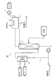
- FIG. 1 The whole block diagram of the tritium water distillation apparatus 1 which concerns on Embodiment 1.
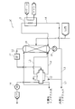
- FIG. The whole block diagram of the tritium water distillation apparatus 1A which concerns on Embodiment 2.
- FIG. The whole block diagram of the tritium water distillation apparatus 1B which concerns on Embodiment 3.
- FIG. The whole block diagram of the tritium water distillation apparatus 1C which concerns on Embodiment 4.
- FIG. The whole block diagram of tritium water distillation apparatus 1D which concerns on Embodiment 5.
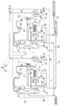
- FIG. The whole block diagram of the tritium water distillation apparatus 1E which concerns on Embodiment 6.
- FIG. 1 is an entire configuration view of a tritium water distillation apparatus 1 according to a first embodiment.
- the stock solution supplied to the tritium water distillation apparatus of the present invention is light water (H 2 O) containing tritium water (HTO or T 2 O).
- the tritiated water distillation apparatus of the present invention means that light water (H 2 O) containing tritiated water (HTO or T 2 O) supplied as a stock solution is lower than the tritium water and stock solution having a higher concentration than the stock solution. It means an apparatus that separates into tritium water of concentration.
- the tritium water distillation apparatus 1 has a distillation column 2 for performing distillation at a temperature range of 50 to 70.degree.
- the distillation column 2 is a packed multistage distillation column, and an adsorbent is used as a packing material.
- Silica gel is used as the "adsorbent".
- zeolite for example, synthetic zeolite such as NaX-type zeolite, Y-type zeolite, Mg-type zeolite
- activated alumina activated carbon
- mesoporous silica etc.
- FSM-16, MCM -41, MCM-48 or the like may be used.
- the “adsorbent” used in Embodiment 2-4 to be described later is also the same as in Embodiment 1, and silica gel, molecular sieve, zeolite (for example, synthesis of NaX-type zeolite, Y-type zeolite, Mg-type zeolite, etc.) Zeolite), activated alumina, activated carbon, mesoporous silica, etc. (eg, FSM-16, MCM-41, MCM-48), etc. may be used.
- the distillation column 2 is provided with a condenser 3 at the top.
- a vacuum pump 5 is connected to the condenser 3.
- the inside of the distillation column 2 is maintained at a predetermined high degree of vacuum by the vacuum pump 5, and as a result, in the distillation column 2, the stock solution can be distilled at a temperature range of 50 to 70 ° C. .
- the heating circulation path Ll is piped at the bottom of the distillation column 2.
- the heating circulation path Ll is provided with a circulation pump 6 for circulating the reservoir liquid at the bottom of the column, and a heater (corresponding to a reboiler) 4 for heating the reservoir liquid. Steam is supplied to the heater 4 so as to heat the storage fluid circulating in the heating circulation path Ll.
- the heater (corresponding to a reboiler) 4 may be a horizontal pipe heat exchanger.
- the stock solution is supplied to the top of the distillation column 2.
- 62 types of radioactive substances and scale components have been removed by pretreatment. That is, 62 radioactive materials (except for tritium) are removed from polluted water by a multi-nuclide removal facility (ALPS), and non-volatile components such as salts and scale components are further removed by an evaporation and concentration device.
- APS multi-nuclide removal facility
- non-volatile components such as salts and scale components are further removed by an evaporation and concentration device.
- the stock solution is pretreated as described above.
- the processing operation of the tritium water distillation apparatus 1 of the said structure is demonstrated.
- the stock solution at 25 ° C. is supplied to the top of the distillation column 2, flows down in the distillation column 2, and is stored at the bottom of the distillation column 2.
- the storage liquid circulates through the heating circulation path Ll, is heated in the heater 4 and is evaporated and supplied to the bottom of the column.
- the liquid heated and supplied to the bottom of the column generates vapor by flash evaporation.
- the generated vapor ascends in the distillation column 2 and is brought into gas-liquid contact with the undiluted solution which descends in the distillation column 2.
- the rising vapor and the falling liquid are brought into gas-liquid contact on the surface of the adsorbent packed in the distillation column 2, and the heat necessary for the liquid to evaporate, ie, the latent heat of evaporation, is exchanged. Then, since the inside of the distillation column 2 is maintained at a predetermined degree of vacuum, the descending liquid evaporates in a temperature range of 50 to 70 ° C., and the generated vapors rise to the top of the column. In the course of the gas-liquid contact, the tritium concentration in the downflow increases and the tritium concentration in the upflow decreases.
- the rising vapor after the gas-liquid contact reaches the top of the column, and is further led to the condenser 3.
- the supplied steam is cooled by the cooling water and discharged as low concentration tritium water having a tritium concentration lower than that of the stock solution.
- the descending liquid after gas-liquid contact is stored at the bottom of the column, and a part of the stored liquid is recovered as high-concentration tritium water having a higher tritium concentration than the undiluted solution.
- separation performance is remarkably improved by using the adsorbent as a packing material for the distillation column and performing distillation at a temperature range of 50 to 70 ° C., and the number of theoretical plates can be reduced to a practicable level, It is possible to miniaturize a practicable device.
- FIG. 2 is an entire configuration diagram of a tritium water distillation apparatus 1A according to a second embodiment.
- the tritium water distillation apparatus 1A is the same as the tritium water distillation apparatus 1 according to the first embodiment in that it includes a single distillation column, and the heat pump 11 is included in the above embodiment. This is different from the tritium water distillation apparatus 1 according to 1.
- the configuration of the tritium water distillation apparatus 1A will be described below with reference to FIG.
- the tritium water distillation apparatus 1A has a distillation column 10 for performing distillation at a temperature range of 50 to 70.degree.
- the distillation column 10 is a packed multistage distillation column, and an adsorbent is used as a packing material.
- a heat pump 11 as a compressor is connected to the top of the distillation column 10 via a pipe L2.
- the heat pump 11 compresses and heats the vapor from the top of the distillation column 10, and the compressed and heated vapor is supplied to the reboiler 12 and is used as a heating source of the reboiler 12.
- a vacuum pump 14 is connected to the reboiler 12.
- the inside of the distillation column 10 and the heat pump 11 is maintained at a predetermined high degree of vacuum by the vacuum pump 14, and as a result, in the distillation column 10, the stock solution can be distilled at a temperature range of 50 to 70 ° C. It is done.
- the reboiler 12 may be a horizontal pipe heat exchanger.
- a supply line L3 for supplying the bottom liquid to the reboiler 12 is provided.
- the start-up heater 13 is provided so that external heat can be supplied at the time of start-up and when an auxiliary heat source for maintaining the operating temperature is required. That is, the start-up heating line L6 is connected to the bottom of the distillation column 10, and the start-up heating line L6 is provided with the circulation pump 15 and the start-up heater 13. At start-up, the circulation pump 15 is driven, and the distillation column 10 bottom portion storage liquid circulates the start-up heating line L6, is heated in the start-up heater 13, evaporates, and is supplied to the column bottom .
- the processing operation of the tritium water distillation apparatus 1 of the said structure is demonstrated.
- the stock solution at 25 ° C. is supplied to the top of the distillation column 10, flows down in the distillation column 10, and reaches the bottom of the distillation column 10 and is stored.
- the bottom liquid of the distillation column 10 circulates the heating line L6 for activation, is heated in the heater 13 for activation, is supplied to the bottom of the column, and generates vapor by flash evaporation.
- the heated steam generated at the bottom of the column ascends in the distillation column 10 and is brought into gas-liquid contact with the undiluted solution which descends in the distillation column 10.
- the rising vapor and the falling liquid come into gas-liquid contact on the surface of the adsorbent packed in the distillation column, and the heat necessary for the liquid to evaporate, ie, the latent heat of vaporization, is exchanged. Then, since the inside of the distillation column 10 is maintained at a predetermined degree of vacuum, the descending liquid evaporates in the temperature range of 50 to 70 ° C. and rises to the top of the column. In the course of the gas-liquid contact, the tritium concentration in the downflow increases and the tritium concentration in the upflow decreases.
- the rising vapor after the gas-liquid contact reaches the top of the distillation column 10 and is further led to the heat pump 11.
- the supplied steam is compressed and heated to be used as a heat source of the reboiler 12.
- the bottom storage liquid supplied through the supply line L3 is heated and returned to the bottom through the supply line L4, and the vapor flash-evaporated by the reboiler 12 is returned to the bottom through the supply line L5.
- the heated steam returned to the bottom of the column ascends again in the distillation column 10, gas-liquid contact is made with the undiluted solution that descends in the distillation column 10, and the tritium concentration in the descending liquid increases. Tritium concentration decreases. Then, such a series of processing is repeatedly performed.
- the concentration of the storage liquid becomes high at the bottom of the distillation column 10, and a part of the storage liquid passes through the supply line L3 and the discharge line L7, and the concentration of tritium is higher It is recovered as high concentration tritium water.
- the steam supplied from the heat pump 11 to the reboiler 12 is heat exchanged with the bottom reservoir liquid in the reboiler 12, cooled and condensed, and discharged as low concentration tritium water having a tritium concentration lower than that of the undiluted solution.
- the separation performance is significantly improved by using the adsorbent as the packing material for the distillation column and performing distillation in the temperature range of 50 to 70 ° C., and the number of theoretical plates is increased. Can be reduced to a practicable level, and miniaturization of a practicable device can be achieved.
- energy efficiency is improved and energy saving is achieved.
- FIG. 3 is a whole block diagram of a tritium water distillation apparatus 1B according to a third embodiment.
- the third embodiment is similar to the first embodiment, and the corresponding parts are denoted by the same reference numerals.
- the stock solution is configured to be supplied to the top of the distillation column 2.
- the stock solution is supplied to the middle portion of the distillation column 2 as shown in FIG.
- part of the condensed water (tritium water) from the condenser 3 is refluxed to the top of the distillation column 2, and part is discharged as low concentration tritium water having a tritium concentration lower than that of the stock solution.
- the concentration of the undiluted solution and the concentration in the distilling column 2 become substantially the same by the configuration in which such undiluted solution is supplied to the middle part of the distilling column 2, more preferable distillation processing becomes possible.
- FIG. 4 is an entire configuration diagram of a tritium water distillation apparatus 1C according to a fourth embodiment.
- the fourth embodiment is similar to the second embodiment, and corresponding parts are denoted with the same reference numerals.
- the stock solution is configured to be supplied to the top of the distillation column 10.
- the stock solution is supplied to the middle portion of the distillation column 10 as shown in FIG.
- the condensed water (tritium water) from the reboiler 12 is partly refluxed to the top of the distillation column 10 and partly discharged as low concentration tritium water having a tritium concentration lower than that of the stock solution. . Since the concentration of the undiluted solution and the concentration in the distilling column 10 become substantially the same by the configuration in which such undiluted solution is supplied to the middle part of the distilling column 10, more preferable distillation processing is possible.
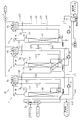
- FIG. 4 is an entire configuration diagram of a tritium water distillation apparatus 1D according to a fifth embodiment.
- the tritium water distillation apparatus 1D includes a plurality of (three in this embodiment) distillation column groups. That is, the tritium water distillation apparatus 1D has a first distillation column group F1, a second distillation column group F2, and a third distillation column group F3.
- the first distillation column group F1 has a first distillation column A1 for performing distillation at a temperature range of 50 to 70 ° C., a first heat pump B1 as a compressor, a first reboiler R1, and a first circulation pump P1.
- the second distillation column group F2 and the third distillation column group F3 also have the same configuration as the first distillation column group F1. That is, the second distillation column group F2 also has a second distillation column A2, a second heat pump B2, a second reboiler R2 and a second circulation pump P2 for performing distillation at a temperature range of 50 to 70 ° C.
- the distillation column group F3 also has a third distillation column A3, a third heat pump B3, a third reboiler R3 and a third circulation pump P3 for performing distillation at a temperature range of 50 to 70.degree.
- These distillation columns A1, A2 and A3 are packed multistage distillation columns, and an adsorbent is used as a filler.
- the stock solution is supplied to the second distillation column A2, and the stock solution is the second distillation column so that the concentration of tritium water processed in the second distillation column A2 and the concentration of tritium water in the stock solution become the same. It is supplied to the middle part of A2. Further, a vacuum pump P is connected to the reboilers R1, R2 and R3 so that the heat pumps B1, B2 and B3 and the interiors of the distillation columns A1, A2 and A3 are maintained at a predetermined high degree of vacuum. In A1, A2 and A3, the stock solution is configured to be capable of distillation at a temperature range of 50 to 70.degree.
- the first distillation column group F1 includes the start heater 20. That is, the start-up heating line L20 is connected to the bottom of the distillation column A1, and the start-up heating line L20 is provided with the circulation pump P1 and the start-up heater 20. At the time of start-up, the liquid stored in the bottom of the first distillation column A1 circulates the start-up heating line L20, is heated in the start-up heater 20 and is evaporated and supplied to the bottom of the column.
- the tritium water distillation apparatus 1D is equipped with a stock solution preheater 21 so that the low concentration tritium water whose concentration is lower than that of the stock solution is heat exchanged with the stock solution at 25 ° C. by the tritium water distillation apparatus 1D.
- the reboilers R1, R2 and R3 may be horizontal pipe heat exchangers.
- the stock solution is supplied to the middle part of the second distillation column A2, flows down in the second distillation column A2, and is stored at the bottom of the second distillation column A2.
- the bottom storage liquid of the second distillation column A2 is supplied to the middle part of the filling portion 60 of the first distillation column A1 through the circulation pump P2 ⁇ the supply line L21, and further flows down the first distillation column A1.
- the bottom of the first distillation column A1 is reached and stored.
- the bottom liquid in the first distillation column A1 circulates through the heating line L20 for activation, is heated in the heater 20 for activation, and evaporates and is supplied to the bottom of the column.
- the heated steam supplied to the bottom of the column ascends in the first distillation column A1, and is brought into gas-liquid contact with the undiluted solution which descends in the first distillation column A1.
- the inside of the distillation column A1 is maintained at a predetermined degree of vacuum, the descending liquid evaporates in the temperature range of 50 to 70 ° C. and rises to the top of the column.
- the tritium concentration in the downflow increases and the tritium concentration in the upflow decreases.
- the rising vapor after the gas-liquid contact reaches the top of the first distillation column A1, and is further led to the first heat pump B1.
- the supplied steam is compressed and heated (58 ° C.) to be a heat source of the first reboiler R1.
- the bottom reservoir liquid of the first distillation column A1 supplied through the supply line L22 is heated and returned to the bottom of the first distillation column A1 through the supply line L23, and heated and evaporated in the reboiler R1.
- the 55 ° C. vapor is returned to the bottom of the first distillation column A1 through the supply line L24.
- the storage liquid has a high concentration, and a part of the bottom storage liquid is recovered as high-concentration tritium water having a higher tritium concentration than the stock solution through the discharge line L40. Be done.
- the steam supplied from the first heat pump B1 to the first reboiler R1 is heat-exchanged in the first reboiler R1 to be cooled and condensed, and the condensed water (tritium water) from the first reboiler R1 is discharged from the discharge lines L50, L51. Then, it is refluxed to the top of the first distillation column A1.
- the condensed water (tritium water) from the first reboiler R1 passes through the discharge lines L50 and L52, and is subjected to the second distillation as tritium water whose concentration of tritium has been reduced compared to the bottom liquid of the first distillation column A1. It is supplied to the middle part of tower A2.
- the bottom liquid in the second distillation column A2 is heated by the second reboiler R2 and returned to the bottom as heated steam.
- the heating vapor ascends in the second distillation column A 2, and in the lower filling unit 51, the liquid mixture is brought into contact with the mixture of the descending liquid descending the upper filling unit 50 and the stock solution descending the lower filling unit 51.
- the heating steam ascends the upper filling portion 50 of the second distillation column A2
- the descending liquid which descends the upper filling portion 50 (from the second reboiler R2 through the discharge lines L53 and L54 to the second distillation column A2 Gas-liquid contact is made with condensed water (tritium water) returned to the top of the column.
- the second distillation column A2 since the second distillation column A2 is maintained at a predetermined degree of vacuum, the descending liquid evaporates in the temperature range of 50 to 70 ° C. and rises to the top of the column. In the course of the gas-liquid contact, the tritium concentration in the downflow increases and the tritium concentration in the upflow decreases.
- the rising vapor after the gas-liquid contact reaches the top of the second distillation column A2, and is further led to the second heat pump B2.
- the supplied steam is compressed and heated (58 ° C.) to be a heat source of the second reboiler R2.
- the bottom reservoir liquid of the second distillation column A2 supplied via the supply line L25 is heated and returned to the bottom of the second distillation column A2 via the supply line L26, and at the same time the second reboiler R2
- the heated and evaporated 55 ° C. vapor is returned to the bottom of the second distillation column A2 through the supply line L27.
- the steam supplied from the second heat pump B2 to the second reboiler R2 is heat-exchanged in the second reboiler R2 to be cooled and condensed, and the condensed water (tritium water) from the second reboiler R2 passes through the discharge lines L53, L54. It is refluxed at the top of the second distillation column A2.
- the condensed water (tritium water) from the second reboiler R2 passes through the discharge lines L53 and L55, and is subjected to the third distillation as tritium water whose concentration of tritium has been reduced compared to the bottom liquid of the second distillation column A2. It is supplied to the middle part of the filling section 61 of the column A3.
- the bottom liquid in the third distillation column A3 is heated by the third reboiler R3 and returned to the bottom as heated steam.
- This heating steam is the third distillation column A
- And descent in the third distillation column A3 condensed water (tritiated water) returned to the top of the third distillation column A3 from the third reboiler R3 through the discharge lines L29 and L31
- Gas-liquid contact is performed.
- the inside of the distillation column A3 is maintained at a predetermined degree of vacuum, the descending liquid evaporates in the temperature range of 50 to 70 ° C. and rises to the top of the column.
- the tritium concentration in the downflow increases and the tritium concentration in the upflow decreases.
- the rising vapor after the gas-liquid contact reaches the top of the third distillation column A3, and is further led to the third heat pump B3.
- the supplied steam is compressed and heated (58 ° C.) to be used as a heat source of the third reboiler R3.
- the bottom reservoir liquid of the third distillation column A3 supplied via the supply line L32 is heated and returned to the bottom of the third distillation column A3 via the supply line L33, and the third reboiler R3
- the vapor heated at 55 ° C. is evaporated back to the bottom of the third distillation column A3 through the supply line L34.
- the steam supplied from the third heat pump B3 to the third reboiler R3 is heat-exchanged in the third reboiler R3 to be cooled and condensed, and the condensed water (tritium water) from the third reboiler R3 is partially 3 Refluxes to the top of the distillation column A3 and a part thereof is discharged as low concentration tritium water having a tritium concentration lower than that of the stock solution through discharge lines L29 and L30 and the preliminary heat exchanger 21.
- the tritium concentration of the bottom liquid in the column bottom liquid is high, medium, low, in the order of the first distillation column A1, the second distillation column A2, and the third distillation column A3. It will decline.
- the separation performance is remarkably improved by using an adsorbent as a packing material for the distillation column and performing distillation in a temperature range of 50 to 70 ° C., and the number of theoretical plates is increased. Can be reduced to a practicable level, and miniaturization of a practicable device can be achieved.
- tritium water distillation apparatus 1D was the structure which made the distilling column three towers, according to how much the amount of processing of undiluted
- FIG. 6 is an entire configuration diagram of a tritium water distillation apparatus 1E according to a sixth embodiment.
- the tritium water distillation apparatus 1E is characterized in that two distillation column groups having the same configuration are connected in series to constitute one unit, and one or a plurality of units are arranged.
- the sixth embodiment is an example in which one unit is arranged.
- the tritium water distillation apparatus 1E includes a first distillation column group D1 and a second distillation column group D2 connected in series to the first distillation column group D1.
- the first distillation column group D1 and the second distillation column group D2 have the same configuration.
- the first distillation column group D1 has a first distillation column E1 that performs distillation at a temperature range of 50 to 70 ° C., a heat pump G1 as a compressor, and a reboiler H1.
- a horizontal pipe evaporator (corresponding to a horizontal pipe heat exchanger) is used as the reboiler H1.
- the horizontal pipe type evaporator includes an evaporator I1, which is formed in a cylindrical shape so that the stock solution can be stored therein.
- a heater J1 comprising a pair of left and right headers a1 and b1 and a large number of horizontal heat transfer pipes c1 connecting the two headers a1 and b1 is provided.
- the horizontal pipe evaporator has a circulation channel K1 for treated water (condensed water).
- a condensed water (separated water) pump M1 and a spreader N1 are disposed in the circulation passage K1.
- the condensed water pump M1 is connected to the bottom of the header b1.
- the heating steam from the heat pump G1 enters the header a1 and is guided to the inside of the horizontal heat transfer tube c1 to evaporate the circulating liquid (stock solution) dispersed to the outside of the horizontal heat transfer tube c1 and simultaneously condense to become condensed water, It is transferred to the spreader N1 through the header b1, the condensed water pump M1, and the pipe d1.
- a part of the condensed water is supplied to the filling portion 71 of the distillation column E2 of the second distillation column group D2 through the header b1, the condensed water pump M1, and the pipe g1.
- the horizontal tube evaporator has a circulation channel h1 for the stock solution.
- a circulation pump Q1 and a spreader S1 are disposed in the circulation flow path h1.
- the circulation pump Q1 is connected to the bottom of the first distillation column E1.
- the circulation pump Q1 is formed so as to be able to transfer the stock solution (containing the concentrated solution of the stock solution) stored in the bottom of the first distillation column E1 to the spreader S1 through the pipe m1.
- the circulation pump Q1 is formed so as to be able to recover a part of the concentrated solution in which the undiluted solution is concentrated through the pipe t1 and discharge it as highly concentrated tritiated water to the outside of the system.
- the spreader S1 is formed to scatter the stock solution from above the horizontal heat transfer tube c1 toward the horizontal heat transfer tube c1.
- the outlet side of the heat pump G1 is connected to the header a1 of the heater J1.
- a vacuum pump T1 is connected to the header a1 of the heater J1 via a bleed scrubber V1.
- the vacuum pump T1 holds the inside of the evaporator I1 and the inside of the heat pump G1 in vacuum.
- An upper portion of the bleed scrubber V1 is provided with a spreader W1, and a lower portion of the bleed scrubber V1 is supplied with bleed steam remaining inside the header a1.
- Reservoir at the bottom of the heater J1 is sprayed from the sprayer W1 through the pipe r1 by the condensed water pump M1, thereby cooling the bleed steam drawn from the header a1 to the bleed scrubber V1.
- tritium contained in the extracted steam is prevented from being discharged to the outside.
- a storage tank U1 and a cooler Z1 are provided in an exhaust line e1 connected to the vacuum pump T1. The steam remaining on the top of the bleed scrubber V1 is led to the cooler Z1 via the vacuum pump T1 and cooled by the cooler Z1.
- the tritium contained in the exhaust vapor led to the cooler Z1 is prevented from being discharged to the outside.
- the bleed steam remaining in the header a1 is discharged to the outside by the bleed scrubber V1 and the cooler Z1
- the tritium contained in the bleed vapor is prevented as much as possible from being discharged to the outside.
- the liquid stored in the storage tank U1 is partially discharged to the outside of the system by the sealing water pump X1, and most of the liquid is cooled and transferred to the vacuum pump T1 and the cooler Z1.
- the second distillation column group D2 has the same configuration as the first distillation column group D1, and reference is made to each constituent portion of the second distillation column group D2 corresponding to each constituent portion of the first distillation column group D1.
- the code is shown with the suffix 2 attached.
- the distillation column of the second distillation column group D2 is indicated by the reference symbol E2
- the heat pump of the second distillation column group D2 is indicated by the reference symbol G2
- the reboiler of the second distillation column group D2 is indicated by the reference symbol H2.
- the components of the other second distillation column group D2 are also indicated by the same notation.
- the processing operation of the distillation apparatus 1E configured as described above will be described.
- the processing operation of the first distillation column group D1 will be described.
- the vacuum pump T1 By driving the vacuum pump T1, the inside of the evaporator I1, the distillation column E1, and the heat pump G1 is maintained at a predetermined high degree of vacuum.
- the stock solution is fed through the stock solution feed pipe 50 to the middle of the packed section 70 of the distillation column E1.
- the circulation pump Q1 the circulation liquid (containing the stock solution and the concentrated water) stored at the bottom of the distillation column E1 is supplied to the spreader S1 through the pipe m1, and the spreader S1 to the horizontal heat transfer pipe c1. It is scattered towards.
- the circulating liquid sprayed by the sprayer S1 is thin film-evaporated on the surface of the horizontal heat transfer tube c1, and heated steam is generated.
- the heated steam is supplied to the bottom of the distillation column E1 and ascends in the distillation column E1.
- the treated water (condensed water) supplied to the top of the distillation column E1 from the header b1 through the pipe d1 by the condensed water pump M1 flows down in the distillation column E1.
- the tritium concentration in the descending liquid is reduced by the contact between the heating steam rising in the distillation column E1 and the treated water (condensed water) flowing down in the distillation column E1. It increases and tritium concentration in the rising vapor decreases.
- the vapor whose tritium concentration has been reduced is taken out from the top of the column.
- the vapor extracted from the top of the tower is led to the heat pump G1.
- the heat pump G1 compresses and raises the temperature of the supplied steam, and uses it as a heat source of the reboiler H1. That is, the steam led to the heat pump H1 is adiabatically compressed by the heat pump H1 and sent to the header a1 after the temperature and pressure rise.
- the vapor that has entered the header a1 is guided to the inside of the horizontal heat transfer tube c1, and thin film evaporates the circulating liquid that is dispersed to the outside of the horizontal heat transfer tube c1.
- the vapor generated by thin film evaporation ascends again in the distillation column E1 and is brought into gas-liquid contact with treated water (condensed water) which descends in the distillation column E1 from the top of the column.
- treated water condensed water
- the tritium concentration in the descending liquid is It increases and tritium concentration in the rising vapor decreases.
- the remaining circulating liquid which has not been thin film evaporated is stored at the bottom of the evaporator I1. Then, by repeating such a series of processes, the circulating fluid is concentrated and discharged from the pipe t1 as a high concentration and lithium water to the outside of the system.
- the thin film evaporation leads to the inside of the horizontal heat transfer tube c1 and the vapor is simultaneously condensed and led to the header b1, and a part thereof is again supplied to the top of the distillation column E1 through the pipe d1 as condensed water.
- a part thereof is supplied as treated water (low concentration tritium water having a lower tritium concentration than the stock solution) through the pipe g1 to the packed portion 71 of the distillation column E2 of the second distillation column group D2.
- the processing operation of the second distillation column group D2 is basically the same as the processing operation of the first distillation column group D1.
- the different processing operations are as follows. That is, the treated water (low concentration tritium water having a lower tritium concentration than the stock solution) distilled and separated in the first distillation column group D1 is supplied to the middle part of the packed portion 71 of the distillation column D2. Also, the high concentration tritiated water which has a high concentration by the processing operation of the second distillation column group D2 is returned from the bottom of the distillation column E2 to the filling section 70 of the distillation column E1 of the first distillation column group D1 through the pipe 51.
- a portion of the condensed water led to the header b2 in the second distillation column group D2 is supplied to the top of the distillation column E2 through the pipe d2, and a portion thereof is a low concentration having a tritium concentration lower than that of the stock solution. It is discharged out of the system through the pipe 52 as tritiated water.
- each distillation column group D1, D2 is set to a function to be concentrated 10 times. As a result, it becomes possible to lower the tritium concentration by one digit in the first distillation column group D1 and further reduce it by one digit in the second distillation column group D2, and easily design a configuration to reduce the tritium concentration as a whole by two digits. It will be possible.
- these two distillation column groups D1 and D2 are configured as one unit, and the amount of undiluted solution to be evaporated and concentrated, And one or more units consisting of the first distillation column group and the second distillation column group depending on the tritium concentration required for treated water after evaporation and concentration, the tritium actually required It becomes possible to easily design and arrange a distillation apparatus that enables high concentration volume reduction and low concentration processing of water.
- the embodiment 1-6 is configured to perform distillation in the temperature range of 50 to 70 ° C.
- the configuration is such that distillation is performed in the temperature range of 70 ° C. or less, which is greater than 40 ° C. It is also good.
- the preferable temperature range is 50 to 70 ° C.
- the present invention is applicable to a tritium water distillation apparatus, a tritium water distillation method, and the like.
Landscapes
- Chemical & Material Sciences (AREA)
- Chemical Kinetics & Catalysis (AREA)
- Physics & Mathematics (AREA)
- Engineering & Computer Science (AREA)
- General Engineering & Computer Science (AREA)
- High Energy & Nuclear Physics (AREA)
- Vaporization, Distillation, Condensation, Sublimation, And Cold Traps (AREA)
Abstract
分離性能(比揮発度)が格段に向上し、理論段数を実用可能レベルまで小さくでき、実用可能な装置の小型化を図ることができるトリチウム水蒸留装置及びトリチウム水蒸留方法を提供する。 トリチウム水蒸留装置1は、原液として供給される、トリチウム水(HTO又はT2O)を含む軽水(H2O)を、原液よりも高濃度のトリチウム水と原液よりも低濃度のトリチウム水とに分離する装置である。蒸留装置1は40℃よりも大きく70℃以下の温度範囲で蒸留を行う蒸留塔2を有し、蒸留塔2は充填材として吸着剤を使用する。蒸留塔2は塔頂部に凝縮器3を備え、凝縮器3には真空ポンプ5が接続されている。真空ポンプ5によって蒸留塔2内部が所定の高真空度に保持され、蒸留塔2において原液を40℃よりも大きく70℃以下の温度範囲で蒸留を行う。尚、蒸留を行う温度範囲は、好ましくは、50~70℃である。
Description
本発明は、低濃度で且つ大量のトリチウムを含む汚染水の処理に際して、分離性能が向上し、理論段数が小さく、装置の小型化が図れることによって、実用的なレベルでの処理を可能としたトリチウム水蒸留装置及びトリチウム水蒸留方法に関する。
原発の汚染水処理として、多核種除去設備(ALPS)では62種の放射性物質の除去が可能になっているが、トリチウムだけは除去できずタンクに貯蔵されている。そのため、トリチウムを含む汚染水の処理が問題となっており、トリチウムを含む汚染水のトリチウム濃度を法的規制値(6×10⁴Bq/L)以下まで下げることが要請されている。
ここで、トリチウムは水素の同位体であり、トリチウム水(HTO又はT2O)の形態で存在するため、軽水(H2O)とトリチウム水(HTO又はT2O)との分離が困難とされている。
トリチウム除去技術の従来例としては、水蒸留法がある。この水蒸留法は軽水(H2O)とトリチウム水(HTO又はT2O)の蒸気圧の違いにより分離する方法である。
ここで、トリチウムは水素の同位体であり、トリチウム水(HTO又はT2O)の形態で存在するため、軽水(H2O)とトリチウム水(HTO又はT2O)との分離が困難とされている。
トリチウム除去技術の従来例としては、水蒸留法がある。この水蒸留法は軽水(H2O)とトリチウム水(HTO又はT2O)の蒸気圧の違いにより分離する方法である。
しかし、低濃度でかつ大量のトリチウムを含む汚染水を処理するには、分離性能が小さく、理論段数が大きくなり、装置の大型化やエネルギー消費が大きいという問題がある(下記の非特許文献1の193頁、右欄5行目~10行目参照)。なお、非特許文献1には、低濃度の重水について分離性能が小さく、理論段数が大きくなることが記載されており、当該記載はトリチウムについても当てはまる。
日本海水学会誌、第43巻、第4号、「重水製造法と蒸発法海水淡水化装置における重水の濃縮」
そこで、分離性能(比揮発度)が向上し、理論段数が小さくできる水蒸留法を用いた装置が所望されていた。
本願発明は、上記課題に鑑みて考え出されたものであり、その目的は、分離性能(比揮発度)が格段に向上し、理論段数を実用可能レベルまで小さくでき、実用可能な装置の小型化を図ることができるトリチウム水蒸留装置及びトリチウム水蒸留方法を提供することである。
上記目的を達成するために請求項1記載の発明は、蒸留塔を備え、原液として供給される、トリチウム水(HTO又はT2O)を含む軽水(H2O)を、原液よりも高濃度のトリチウム水と原液よりも低濃度のトリチウム水とに分離するトリチウム水蒸留装置であって、前記蒸留塔の充填材として吸着機能を有する充填材を使用すると共に、この蒸留塔によって40℃よりも大きく70℃以下の温度範囲で蒸留を行うことを特徴とする。
「吸着機能を有する充填材」とは、吸着剤そのものを充填材として使用する場合、規則充填物に粉状または球状の吸着剤を入れて使用する場合、及び、充填材に吸着層が形成されている場合を含む。
(1)「吸着剤そのものを充填材として使用する場合」とは、シリカゲル等の吸着剤そのものを充填材として使用する場合である。「吸着剤」としては、シリカゲルの他に、モレキュラーシーブ、ゼオライト(例えばNaX型ゼオライト、Y型ゼオライト、Mg型ゼオライト等の合成ゼオライト)、活性アルミナ、活性炭、メソポーラスシリカ等(例えばFSM-16、MCM-41、MCM-48)等が含まれる。
(2)「規則性充填物に粉状または球状の吸着剤を入れて使用する場合」とは、Katapak-SPのような市販の触媒用規則充填物に、粉状または球状の吸着剤を入れて使用する場合である。
(3)「充填材に吸着層が形成されている場合」とは、所定形状の充填基材(例えばラシヒリング)の表面に、選択吸着性材料から成る吸着層(例えばNaX型などのゼオライト層)が形成された充填材を使用する場合である。
(2)「規則性充填物に粉状または球状の吸着剤を入れて使用する場合」とは、Katapak-SPのような市販の触媒用規則充填物に、粉状または球状の吸着剤を入れて使用する場合である。
(3)「充填材に吸着層が形成されている場合」とは、所定形状の充填基材(例えばラシヒリング)の表面に、選択吸着性材料から成る吸着層(例えばNaX型などのゼオライト層)が形成された充填材を使用する場合である。
(A)「所定形状の充填基材」とは、ラシヒリングのような市販の不規則充填物を意味する。「不規則充填物」としては、ラシヒリングの他に、ベルルサドル、インターロックスサドル等であってもよい。また、所定形状の充填基材は、金属製、樹脂製、セラミック製、ガラス製のいずれであってもよい。
(B)「選択吸着性材料」としては、選択吸着性がある材料であれば特に限定されず、NaX型以外のゼオライトも適用可能である。また、シリカゲルや吸着機能を様々にデザインして製造されるメソポーラスシリカ等(例えばFSM-16、MCM-41、MCM-48)の粉末状で得られる材料も、泳動電着法で金属の表面に電着させることができ、また、ガラス基板上に薄膜としてこれらを作製することも可能である。
なお、「選択吸着性材料」と「所定形状の充填基材」とを用いて本発明に係る充填基材を製造する方法としては、選択吸着性材料を基板表面に成膜する公知の製造方法を利用すればよい。以下に、代表的な製造方法を例示する。
なお、「選択吸着性材料」と「所定形状の充填基材」とを用いて本発明に係る充填基材を製造する方法としては、選択吸着性材料を基板表面に成膜する公知の製造方法を利用すればよい。以下に、代表的な製造方法を例示する。
(b1)金属製基板にメソポーラスシリカを成膜
泳動電着法により、メソポーラスシリカ粉末を金属製基板上に固定化する。具体的には、電着浴としてアセトンを用いて、このアセトン溶液にメソポーラスシリカ粉末を入れてメソポーラスシリカ粒子を分散・懸濁状態とし、アセトン溶液中の電極に10分間直流電流を流す。これにより、帯電したメソポーラスシリカ粒子が金属製基板上に堆積していき、10分間経過後には膜厚約250μmのメソポーラスシリカ膜が形成さる。次いで、メソポーラスシリカ膜が基板を空気中300℃で8時間焼成する。これにより、金属製基板上にバインダーなしでメソポーラスシリカ膜が固定化される(「Adsorption News」Vol.22,No.1(March2008) p8参照)。
上記方法を利用することにより、金属製充填基材表面にメソポーラスシリカ膜(吸着層)が形成され充填材を製造することができる。
泳動電着法により、メソポーラスシリカ粉末を金属製基板上に固定化する。具体的には、電着浴としてアセトンを用いて、このアセトン溶液にメソポーラスシリカ粉末を入れてメソポーラスシリカ粒子を分散・懸濁状態とし、アセトン溶液中の電極に10分間直流電流を流す。これにより、帯電したメソポーラスシリカ粒子が金属製基板上に堆積していき、10分間経過後には膜厚約250μmのメソポーラスシリカ膜が形成さる。次いで、メソポーラスシリカ膜が基板を空気中300℃で8時間焼成する。これにより、金属製基板上にバインダーなしでメソポーラスシリカ膜が固定化される(「Adsorption News」Vol.22,No.1(March2008) p8参照)。
上記方法を利用することにより、金属製充填基材表面にメソポーラスシリカ膜(吸着層)が形成され充填材を製造することができる。
(b2)ガラス基板にシリカ薄膜を成膜
具体的には、有機テンプレート剤にセチルトリメチルアンモニウムブロミド(CTAB)やドデシルトリメチルアンモニウムブロミド(DTAB)、DDAを用い、TEOS(オルトケイ酸テトラエチル)、水等を原料として透明な前駆体溶液を調整する。この溶液をガラス基板上にスピンコートすることにより、ガラス基板上にシリカ薄膜が作製される(「メソポーラスを中心とした多孔質物質の合成とその応用」Nanotechnology,Materials 東海大学出版参照)。
上記方法を利用することにより、ガラス製充填基材表面にメソポーラスシリカ膜(吸着層)が形成され充填材を製造することができる。
具体的には、有機テンプレート剤にセチルトリメチルアンモニウムブロミド(CTAB)やドデシルトリメチルアンモニウムブロミド(DTAB)、DDAを用い、TEOS(オルトケイ酸テトラエチル)、水等を原料として透明な前駆体溶液を調整する。この溶液をガラス基板上にスピンコートすることにより、ガラス基板上にシリカ薄膜が作製される(「メソポーラスを中心とした多孔質物質の合成とその応用」Nanotechnology,Materials 東海大学出版参照)。
上記方法を利用することにより、ガラス製充填基材表面にメソポーラスシリカ膜(吸着層)が形成され充填材を製造することができる。
(b3)多孔質基板でない基板にゼオライト膜を成膜
Al(NO3)3・9H2Oとコロイダルシリカ(触媒化成 Cataloid SI-30)を含む水溶液に、TPABr(tetrapropylammonium bromide)、NaOHを添加し、均一に撹拌して水和ゲルを調製する。ゲルの組成は、H2O/SiO2モル比を80に、0.1TPABr-0.05Na2O-0.01Al2O3-SiO2-80H2Oの組成のものを調整した。次いで、このゲル組成物を、テフロン(登録商標)製内筒を有する30mlのステンレス製オートクレーブに入れ、板状物を溶液に浸漬し、無撹拌状態で、温度170℃、48時間の条件下で水熱反応を行う。この結果、内筒壁面及び板状物面にZSM-5型のゼオライト膜が生成される(特開平06-127937参照)。なお、H2OとSiO2とのモル比、及び温度条件としては、H2O/SiO2モル比が50以上、温度は100℃以上、200℃未満の条件が必要である。
上記方法を利用することにより、多孔質でない充填基材表面にゼオライト膜(吸着層)が形成され充填材を製造することができる。
Al(NO3)3・9H2Oとコロイダルシリカ(触媒化成 Cataloid SI-30)を含む水溶液に、TPABr(tetrapropylammonium bromide)、NaOHを添加し、均一に撹拌して水和ゲルを調製する。ゲルの組成は、H2O/SiO2モル比を80に、0.1TPABr-0.05Na2O-0.01Al2O3-SiO2-80H2Oの組成のものを調整した。次いで、このゲル組成物を、テフロン(登録商標)製内筒を有する30mlのステンレス製オートクレーブに入れ、板状物を溶液に浸漬し、無撹拌状態で、温度170℃、48時間の条件下で水熱反応を行う。この結果、内筒壁面及び板状物面にZSM-5型のゼオライト膜が生成される(特開平06-127937参照)。なお、H2OとSiO2とのモル比、及び温度条件としては、H2O/SiO2モル比が50以上、温度は100℃以上、200℃未満の条件が必要である。
上記方法を利用することにより、多孔質でない充填基材表面にゼオライト膜(吸着層)が形成され充填材を製造することができる。
(C)吸着層は基材の表面全面に形成されていても又はその一部に形成されていてもよい。また、吸着層の厚みは、特に限定されるものではない。
なお、蒸留塔の充填材として、所定形状の充填基材の表面に、選択吸着性材料から成る吸着層が形成された充填材を用いることにより、還流比及び理論段数を大幅に小さくし、且つ、蒸留塔の圧力損失を実用的なレベルにすることが可能となる。
なお、蒸留塔の充填材として、所定形状の充填基材の表面に、選択吸着性材料から成る吸着層が形成された充填材を用いることにより、還流比及び理論段数を大幅に小さくし、且つ、蒸留塔の圧力損失を実用的なレベルにすることが可能となる。
上記の如く、蒸留塔の充填材として「吸着機能を有する充填材」を使用すると、比揮発度が向上することが知られており、この充填材として吸着剤を使用する構成に加えて、40℃よりも大きく70℃以下の温度範囲で蒸留を行うことにより、分離性能が格段に向上し、理論段数を実用可能レベルまで小さくでき、実用可能な装置の小型化を図ることができる。
ここで、上記の如く、蒸留塔で蒸留を行う温度範囲を40℃よりも大きく70℃以下に規制するのは以下の理由による。即ち、例えば、以下の請求項2のようなリボイラーの加熱源とするヒートポンプを備えた構成のような場合において、40℃以下の低温で蒸留を行うと、分離性能が向上し、理論段数が小さくできるという利点はあるが、ヒートポンプ(蒸気圧縮機)を容量の大きい大型のものを使用する必要があり、却ってコストの増加、装置の極端な大型化を招き、実用化に不向きなものとなる。
一方、70℃よりも大きい温度で蒸留を行うと、ヒートポンプ(蒸気圧縮機)を容量の大きい大型のものを使用する必要はないが、分離性能(比揮発度)の向上が得られず、実用化に不向きなものとなる。
そこで、分離性能を向上でき、且つ、実用化レベルの容量を備えたヒートポンプの使用を可能として、トリチウム水蒸留装置の実用化を可能とすべく、最適な温度範囲として40℃よりも大きく70℃以下に規制したものである。
ここで、上記の如く、蒸留塔で蒸留を行う温度範囲を40℃よりも大きく70℃以下に規制するのは以下の理由による。即ち、例えば、以下の請求項2のようなリボイラーの加熱源とするヒートポンプを備えた構成のような場合において、40℃以下の低温で蒸留を行うと、分離性能が向上し、理論段数が小さくできるという利点はあるが、ヒートポンプ(蒸気圧縮機)を容量の大きい大型のものを使用する必要があり、却ってコストの増加、装置の極端な大型化を招き、実用化に不向きなものとなる。
一方、70℃よりも大きい温度で蒸留を行うと、ヒートポンプ(蒸気圧縮機)を容量の大きい大型のものを使用する必要はないが、分離性能(比揮発度)の向上が得られず、実用化に不向きなものとなる。
そこで、分離性能を向上でき、且つ、実用化レベルの容量を備えたヒートポンプの使用を可能として、トリチウム水蒸留装置の実用化を可能とすべく、最適な温度範囲として40℃よりも大きく70℃以下に規制したものである。
また、請求項2記載の発明は、請求項1記載のトリチウム水蒸留装置であって、前記40℃よりも大きく70℃以下の温度範囲に代えて、50~70℃の温度範囲で蒸留を行うことを特徴とする。
50~70℃の温度範囲で蒸留を行うことにより、分離性能の向上と装置の小型化の両者をより最適に実現することが可能となる。
また、請求項3記載の発明は、請求項1又は2記載のトリチウム水蒸留装置であって、前記蒸留塔は塔底部に貯まった貯留液を加熱するリボイラーを備えるとともに、前記蒸留塔からの蒸気を圧縮昇温し、リボイラーの加熱源とするヒートポンプを備えていることを特徴とする。
上記構成によれば、蒸留塔からの蒸気を圧縮昇温しリボイラーの加熱源とすることにより、エネルギー効率がよく、省エネルギー化が図られる。
また、請求項4記載の発明は、請求項3記載のトリチウム水蒸留装置であって、前記リボイラーが水平管式熱交換器であることを特徴とする。
上記の如く、水平管式熱交換器を用いることにより、より少ない温度差で溶液を再加熱することができ、省エネルギー化が図れる。
また、請求項5記載の発明は、請求項3又は4記載のトリチウム水蒸留装置であって、前記蒸留塔、前記リボイラー、及び前記ヒートポンプを備えた第1蒸留塔群と、前記第1蒸留塔群と同一構成である第2蒸留塔群であって、第1蒸留塔群の後段に配置され、且つ第1蒸留塔群に直列に連結された第2蒸留塔群と、を備え、これら第1蒸留塔群と第2蒸留塔群を1つのユニットとして構成し、該ユニットを1又は複数個配置して構成されることを特徴とする。
上記構成により、第1蒸留塔群と第2蒸留塔群とは同一構成であるため、各蒸留塔群での分離性能は同じである。従って、例えば、各蒸留塔群で10倍濃縮される機能に設定した場合において、トリチウム濃度を第1蒸留塔群において1桁低下させ、更に第2蒸留塔群において1桁低下させることが可能となり、全体としてトリチウム濃度を2桁落す構成を容易に設計配置できることになる。よって、蒸発濃縮すべき原液量、及び蒸発濃縮された後の処理水に要請されるトリチウム濃度に応じて、第1蒸留塔群と第2蒸留塔群とから成るユニットを1又は複数個配置すれば、現実に必要とされるトリチウム水蒸留装置を設計配置することができる。このように、本発明によれば、トリチウム水蒸留装置の全体構成を効率的かつ機能的に設計することが可能となる。
また、請求項6記載の発明は、請求項1~5の何れかに記載のトリチウム水蒸留装置であって、原液は前処理として蒸発濃縮装置により非揮発性成分が除去されていることを特徴とする。
上記構成によれば、前処理として蒸発濃縮装置により非揮発性成分(例えば塩分、スケール成分など)が除去されることにより、不純物含有量の少ない原液が得られ、蒸留塔で高濃度まで濃縮されても非揮発性成分の付着なしで運転することができる。
また、請求項7記載の発明は、蒸留塔を備え、原液として供給される、トリチウム水(HTO又はT2O)を含む軽水(H2O)を、原液よりも高濃度のトリチウム水と原液よりも低濃度のトリチウム水とに分離するトリチウム水蒸留方法であって、前記蒸留塔の充填材として吸着機能を有する充填材を使用すると共に、この蒸留塔によって40℃よりも大きく70℃以下の温度範囲で蒸留を行うことを特徴とする。
上記構成によれば、分離性能を向上でき、且つ、実用化レベルの容量を備えたヒートポンプの使用を可能とし、実用化が可能なトリチウム水蒸留方法が構築される。
本発明によれば、比揮発度(分離性能)が格段に向上し、この結果、理論段数を実用可能レベルまで小さくでき、実用可能な装置の小型化を図ることができる。
以下、本発明を実施の形態に基づいて詳述する。なお、本発明は、以下の実施の形態に限定されるものではない。
(実施の形態1)
図1は実施の形態1に係るトリチウム水蒸留装置1の全体構成図である。
ここで、本発明のトリチウム水蒸留装置に供給される原液は、トリチウム水(HTO又はT2O)を含む軽水(H2O)である。また、本発明のトリチウム水蒸留装置とは、原液として供給される、トリチウム水(HTO又はT2O)を含む軽水(H2O)を、原液よりも高濃度のトリチウム水と原液よりも低濃度のトリチウム水とに分離する装置を意味する。
(実施の形態1)
図1は実施の形態1に係るトリチウム水蒸留装置1の全体構成図である。
ここで、本発明のトリチウム水蒸留装置に供給される原液は、トリチウム水(HTO又はT2O)を含む軽水(H2O)である。また、本発明のトリチウム水蒸留装置とは、原液として供給される、トリチウム水(HTO又はT2O)を含む軽水(H2O)を、原液よりも高濃度のトリチウム水と原液よりも低濃度のトリチウム水とに分離する装置を意味する。
トリチウム水蒸留装置1は50~70℃の温度範囲で蒸留を行う蒸留塔2を有する。蒸留塔2は充填式の多段の蒸留塔であって、充填材として吸着剤が使用されている。「吸着剤」としてはシリカゲルが用いられている。「吸着剤」としては、シリカゲルの他に、モレキュラーシーブ、ゼオライト(例えばNaX型ゼオライト、Y型ゼオライト、Mg型ゼオライト等の合成ゼオライト)、活性アルミナ、活性炭、メソポーラスシリカ等(例えばFSM-16、MCM-41、MCM-48)等を用いてもよい。なお、後述する実施の形態2-4において使用する「吸着剤」も、実施の形態1と同様であり、シリカゲル、モレキュラーシーブ、ゼオライト(例えばNaX型ゼオライト、Y型ゼオライト、Mg型ゼオライト等の合成ゼオライト)、活性アルミナ、活性炭、メソポーラスシリカ等(例えばFSM-16、MCM-41、MCM-48)等を用いてもよい。
蒸留塔2は塔頂部に凝縮器3を備えている。凝縮器3には真空ポンプ5が接続されている。この真空ポンプ5によって蒸留塔2の内部が所定の高真空度に保持され、この結果、蒸留塔2において、原液を50~70℃の温度範囲で蒸留を行うことができるように構成されている。
また、蒸留塔2は塔底部には加熱循環経路Llが配管されている。加熱循環経路Llには、塔底部の貯留液を循環させる循環ポンプ6と、貯留液を加熱する加熱器(リボイラーに相当)4とが設けられている。加熱器4には蒸気が供給され、加熱循環経路Llを循環する貯留液を加熱するようになっている。なお、加熱器(リボイラーに相当)4は水平管式熱交換器であってもよい。
原液は蒸留塔2の塔頂部に供給される。なお、原液は、前処理によって62種の放射性物質及びスケール成分が除去されている。即ち、汚染水を多核種除去設備(ALPS)により62種の放射性物質(トリチウムを除く)が除去され、更に蒸発濃縮装置により塩分、スケール成分などの非揮発性成分が除かれている。
なお、後述する実施の形態2のトリチウム水蒸留装置1A及び実施の形態3のトリチウム水蒸留装置1Bにおいても、原液は上記と同様の前処理がなされている。
なお、後述する実施の形態2のトリチウム水蒸留装置1A及び実施の形態3のトリチウム水蒸留装置1Bにおいても、原液は上記と同様の前処理がなされている。
次いで、上記構成のトリチウム水蒸留装置1の処理動作について説明する。
先ず、25℃の原液は蒸留塔2の塔頂部に供給され、蒸留塔2内を流下し、蒸留塔2の塔底部に貯留する。この貯留液は、加熱循環経路Llを循環し、加熱器4において加熱されて蒸発し塔底部に供給される。加熱されて塔底部に供給された液は、フラッシュ蒸発によって蒸気を発生させる。発生蒸気は蒸留塔2内を上昇し、蒸留塔2内を下降する原液と気液接触が行われる。即ち、蒸留塔2に充填されている吸着剤の表面において上昇蒸気と下降液体とが気液接触し、液体が蒸発するのに必要な熱、即ち蒸発潜熱がやり取りされる。そして、蒸留塔2内が所定の真空度に維持されていることから、下降液が50~70℃の温度範囲で蒸発し、それぞれ発生した蒸気は塔頂部に上昇していく。この気液接触の過程で、下降液中のトリチウム濃度は増加し、上昇蒸気中のトリチウム濃度は減少する。
先ず、25℃の原液は蒸留塔2の塔頂部に供給され、蒸留塔2内を流下し、蒸留塔2の塔底部に貯留する。この貯留液は、加熱循環経路Llを循環し、加熱器4において加熱されて蒸発し塔底部に供給される。加熱されて塔底部に供給された液は、フラッシュ蒸発によって蒸気を発生させる。発生蒸気は蒸留塔2内を上昇し、蒸留塔2内を下降する原液と気液接触が行われる。即ち、蒸留塔2に充填されている吸着剤の表面において上昇蒸気と下降液体とが気液接触し、液体が蒸発するのに必要な熱、即ち蒸発潜熱がやり取りされる。そして、蒸留塔2内が所定の真空度に維持されていることから、下降液が50~70℃の温度範囲で蒸発し、それぞれ発生した蒸気は塔頂部に上昇していく。この気液接触の過程で、下降液中のトリチウム濃度は増加し、上昇蒸気中のトリチウム濃度は減少する。
そして、気液接触後の上昇蒸気は塔頂部に到達し、更に、凝縮器3に導かれる。凝縮器3では、供給された蒸気が冷却水によって冷却され、原液よりもトリチウム濃度の低い低濃度トリチウム水として排出される。一方、気液接触後の下降液体は塔底部に貯留され、この貯留液の一部は原液よりもトリチウム濃度の高い高濃度トリチウム水として回収される。
このようにして、蒸留塔の充填材として吸着剤を使用すると共に、50~70℃の温度範囲で蒸留を行うことにより、分離性能が格段に向上し、理論段数を実用可能レベルまで小さくでき、実用可能な装置の小型化を図ることができる。
(実施の形態2)
図2は実施の形態2に係るトリチウム水蒸留装置1Aの全体構成図である。トリチウム水蒸留装置1Aは、1つの蒸留塔を備えている構成である点において上記実施の形態1に係るトリチウム水蒸留装置1と同様であり、ヒートホンプ11を備えている点において、上記実施の形態1に係るトリチウム水蒸留装置1と相違する。以下、図2を参照して、トリチウム水蒸留装置1Aの構成を説明する。
図2は実施の形態2に係るトリチウム水蒸留装置1Aの全体構成図である。トリチウム水蒸留装置1Aは、1つの蒸留塔を備えている構成である点において上記実施の形態1に係るトリチウム水蒸留装置1と同様であり、ヒートホンプ11を備えている点において、上記実施の形態1に係るトリチウム水蒸留装置1と相違する。以下、図2を参照して、トリチウム水蒸留装置1Aの構成を説明する。
トリチウム水蒸留装置1Aは、50~70℃の温度範囲で蒸留を行う蒸留塔10を有する。蒸留塔10は充填式の多段の蒸留塔であって、充填材として吸着剤が使用されている。蒸留塔10の塔頂部には配管L2を介して圧縮機としてのヒートポンプ11が接続されている。ヒートポンプ11は蒸留塔10の塔頂部からの蒸気を圧縮昇温し、この圧縮昇温された蒸気はリボイラー12に供給され、リボイラー12の加熱源とされる。リボイラー12には、真空ポンプ14が接続されている。この真空ポンプ14によって蒸留塔10及びヒートポンプ11の内部が所定の高真空度に保持され、この結果、蒸留塔10において、原液を50~70℃の温度範囲で蒸留を行うことができるように構成されている。なお、リボイラー12は水平管式熱交換器であってもよい。
また、蒸留塔10の塔底部には、塔底部貯留液をリボイラー12に供給する供給ラインL3が設けられている。
なお、本実施の形態2は起動用加熱器13を備えており、起動時における場合及び運転温度を維持するための補助熱源が必要な場合に外部熱を供給できるようになっている。即ち、蒸留塔10の塔底部には、起動用加熱ラインL6が配管されており、この起動用加熱ラインL6には循環ポンプ15と起動用加熱器13とが設けられている。起動時には、循環ポンプ15が駆動され、蒸留塔10塔底部貯留液は、起動用加熱ラインL6を循環し、起動用加熱器13において加熱されて蒸発し塔底部に供給されるようになっている。
次いで、上記構成のトリチウム水蒸留装置1の処理動作について説明する。先ず、25℃の原液は蒸留塔10の塔頂部に供給され、蒸留塔10内を流下し、蒸留塔10の塔底部に到達して貯留される。この蒸留塔10の塔底部貯留液は、起動用加熱ラインL6を循環し、起動用加熱器13において加熱されて塔底部に供給され、フラッシュ蒸発によって蒸気を発生させる。この塔底部で発生した加熱蒸気は蒸留塔10内を上昇し、蒸留塔10内を下降する原液と気液接触が行われる。即ち、蒸留塔に充填されている吸着剤の表面において上昇蒸気と下降液体とが気液接触し、液体が蒸発するのに必要な熱、即ち蒸発潜熱がやり取りされる。そして、蒸留塔10内が所定の真空度に維持されていることから、下降液が50~70℃の温度範囲で蒸発し塔頂部に上昇していく。この気液接触の過程で、下降液中のトリチウム濃度は増加し、上昇蒸気中のトリチウム濃度は減少する。
そして、気液接触後の上昇蒸気は蒸留塔10の塔頂部に到達し、更に、ヒートポンプ11に導かれる。ヒートポンプ11では、供給された蒸気を圧縮昇温し、リボイラー12の熱源とする。リボイラー12では、供給ラインL3を経て供給された塔底部貯留液が加熱され、供給ラインL4を経て塔底部に戻されるとともに、リボイラー12でフラッシュ蒸発した蒸気は供給ラインL5を経て塔底部に戻される。そして、塔底部に戻された加熱蒸気は再び蒸留塔10内を上昇し、蒸留塔10内を下降する原液と気液接触が行われ、下降液中のトリチウム濃度は増加し、上昇蒸気中のトリチウム濃度は減少する。そして、このような一連の処理が繰り返し行われる。
一方、上記一連の処理が繰り返し行われることにより、蒸留塔10の塔底部では、貯留液が高濃度となり、貯留液の一部が供給ラインL3、排出ラインL7を通って、原液よりもトリチウム濃度の高い高濃度トリチウム水として回収される。また、ヒートポンプ11からリボイラー12に供給された蒸気は、リボイラー12において塔底部貯留液と熱交換されて冷却凝縮され、原液よりもトリチウム濃度の低い低濃度トリチウム水として排出される。
このようにして、本実施の形態2においても、蒸留塔の充填材として吸着剤を使用すると共に、50~70℃の温度範囲で蒸留を行うことにより、分離性能が格段に向上し、理論段数を実用可能レベルまで小さくでき、実用可能な装置の小型化を図ることができる。加えて、蒸留塔10の塔頂部からの蒸気を圧縮昇温しリボイラー12の加熱源とすることにより、エネルギー効率がよく、省エネルギー化が図られる。
ここで、上記の如く、蒸留塔で蒸留を行う温度範囲を50~70℃に規制する理由をより詳しく説明する。即ち、例えば、リボイラーの加熱源とするヒートポンプを備えた構成のような場合において、50℃以下の低温で蒸留を行うと、分離性能が向上し、理論段数が小さくできるという利点はあるが、ヒートポンプ(蒸気圧縮機)を容量の大きい大型のものを使用する必要があり、却ってコストの増加、装置の極端な大型化を招き、実用化に不向きなものとなる。
一方、70℃よりも大きい温度で蒸留を行うと、ヒートポンプ(蒸気圧縮機)を容量の大きい大型のものを使用する必要はないが、分離性能(比揮発度)の向上が得られず、実用化に不向きなものとなる。
そこで、分離性能を向上でき、且つ、実用化レベルの容量を備えたヒートポンプの使用を可能として、トリチウム水蒸留装置の実用化を可能とすべく、最適な温度範囲として50~70℃に規制したものである。
一方、70℃よりも大きい温度で蒸留を行うと、ヒートポンプ(蒸気圧縮機)を容量の大きい大型のものを使用する必要はないが、分離性能(比揮発度)の向上が得られず、実用化に不向きなものとなる。
そこで、分離性能を向上でき、且つ、実用化レベルの容量を備えたヒートポンプの使用を可能として、トリチウム水蒸留装置の実用化を可能とすべく、最適な温度範囲として50~70℃に規制したものである。
(実施の形態3)
図3は実施の形態3に係るトリチウム水蒸留装置1Bの全体構成図である。本実施の形態3は、実施の形態1に類似し、対応する部分には同一の参照符号を付す。上記実施の形態1では、原液は蒸留塔2の塔頂部に供給するように構成されていたが、本実施の形態3では、図3に示すように原液は蒸留塔2の中間部に供給すると共に、凝縮器3からの凝縮水(トリチウム水)は一部が蒸留塔2の塔頂部に還流され、一部が原液よりもトリチウム濃度の低い低濃度トリチウム水として排出されるように構成されている。このような原液を蒸留塔2の中間部に供給する構成により、原液の濃度と蒸留塔2内の濃度とが略同一となるため、より好ましい蒸留処理が可能となる。
図3は実施の形態3に係るトリチウム水蒸留装置1Bの全体構成図である。本実施の形態3は、実施の形態1に類似し、対応する部分には同一の参照符号を付す。上記実施の形態1では、原液は蒸留塔2の塔頂部に供給するように構成されていたが、本実施の形態3では、図3に示すように原液は蒸留塔2の中間部に供給すると共に、凝縮器3からの凝縮水(トリチウム水)は一部が蒸留塔2の塔頂部に還流され、一部が原液よりもトリチウム濃度の低い低濃度トリチウム水として排出されるように構成されている。このような原液を蒸留塔2の中間部に供給する構成により、原液の濃度と蒸留塔2内の濃度とが略同一となるため、より好ましい蒸留処理が可能となる。
(実施の形態4)
図4は実施の形態4に係るトリチウム水蒸留装置1Cの全体構成図である。本実施の形態4は、実施の形態2に類似し、対応する部分には同一の参照符号を付す。上記実施の形態2では、原液は蒸留塔10の塔頂部に供給するように構成されていたが、本実施の形態4では、図4に示すように原液は蒸留塔10の中間部に供給すると共に、リボイラー12からの凝縮水(トリチウム水)は一部が蒸留塔10の塔頂部に還流され、一部が原液よりもトリチウム濃度の低い低濃度トリチウム水として排出されるように構成されている。このような原液を蒸留塔10の中間部に供給する構成により、原液の濃度と蒸留塔10内の濃度とが略同一となるため、より好ましい蒸留処理が可能となる。
図4は実施の形態4に係るトリチウム水蒸留装置1Cの全体構成図である。本実施の形態4は、実施の形態2に類似し、対応する部分には同一の参照符号を付す。上記実施の形態2では、原液は蒸留塔10の塔頂部に供給するように構成されていたが、本実施の形態4では、図4に示すように原液は蒸留塔10の中間部に供給すると共に、リボイラー12からの凝縮水(トリチウム水)は一部が蒸留塔10の塔頂部に還流され、一部が原液よりもトリチウム濃度の低い低濃度トリチウム水として排出されるように構成されている。このような原液を蒸留塔10の中間部に供給する構成により、原液の濃度と蒸留塔10内の濃度とが略同一となるため、より好ましい蒸留処理が可能となる。
なお、参考まで述べると、以下の実施の形態5、6においては、上記実施の形態3,4において示した(1)原液を蒸留塔の中間部に供給する構成、及び、(2)蒸留塔の塔頂部からの蒸気が凝縮器(リボイラー等の熱交換器を含む)に導かれて凝縮し、この凝縮水(トリチウム水)の一部が蒸留塔の塔頂部に還流する構成が適用されている。
(実施の形態5)
図4は実施の形態5に係るトリチウム水蒸留装置1Dの全体構成図である。トリチウム水蒸留装置1Dは複数個(本実施の形態では3個)の蒸留塔群を備えている。即ち、トリチウム水蒸留装置1Dは、第1蒸留塔群F1、第2蒸留塔群F2及び第3蒸留塔群F3を有している。第1蒸留塔群F1は、50~70℃の温度範囲で蒸留を行う第1蒸留塔A1、圧縮機としての第1ヒートポンプB1、第1リボイラーR1及び第1循環ポンプP1を有している。第2蒸留塔群F2及び第3蒸留塔群F3も第1蒸留塔群F1と同様な構成を有している。即ち、第2蒸留塔群F2も、50~70℃の温度範囲で蒸留を行う第2蒸留塔A2、第2ヒートポンプB2、第2リボイラーR2及び第2循環ポンプP2を有しており、第3蒸留塔群F3も、50~70℃の温度範囲で蒸留を行う第3蒸留塔A3、第3ヒートポンプB3、第3リボイラーR3及び第3循環ポンプP3を有している。これら蒸留塔A1、A2,A3は充填式の多段の蒸留塔であって、充填材として吸着剤が使用されている。
図4は実施の形態5に係るトリチウム水蒸留装置1Dの全体構成図である。トリチウム水蒸留装置1Dは複数個(本実施の形態では3個)の蒸留塔群を備えている。即ち、トリチウム水蒸留装置1Dは、第1蒸留塔群F1、第2蒸留塔群F2及び第3蒸留塔群F3を有している。第1蒸留塔群F1は、50~70℃の温度範囲で蒸留を行う第1蒸留塔A1、圧縮機としての第1ヒートポンプB1、第1リボイラーR1及び第1循環ポンプP1を有している。第2蒸留塔群F2及び第3蒸留塔群F3も第1蒸留塔群F1と同様な構成を有している。即ち、第2蒸留塔群F2も、50~70℃の温度範囲で蒸留を行う第2蒸留塔A2、第2ヒートポンプB2、第2リボイラーR2及び第2循環ポンプP2を有しており、第3蒸留塔群F3も、50~70℃の温度範囲で蒸留を行う第3蒸留塔A3、第3ヒートポンプB3、第3リボイラーR3及び第3循環ポンプP3を有している。これら蒸留塔A1、A2,A3は充填式の多段の蒸留塔であって、充填材として吸着剤が使用されている。
なお、第2蒸留塔A2には原液が供給され、原液は、第2蒸留塔A2内で処理されているトリチウム水濃度と原液のトリチウム水濃度とが同じ濃度となるように、第2蒸留塔A2の中間部へ給液されるようになっている。また、リボイラーR1,R2,R3には真空ポンプPが接続されており、ヒートポンプB1,B2,B3及び蒸留塔A1、A2,A3の内部が所定の高真空度に保持され、この結果、蒸留塔A1、A2,A3において、原液を50~70℃の温度範囲で蒸留を行うことができるように構成されている。
また、第1蒸留塔群F1は起動用加熱器20を備えている。即ち、蒸留塔A1の塔底部には、起動用加熱ラインL20が配管されており、この起動用加熱ラインL20には循環ポンプP1と起動用加熱器20とが設けられている。起動時には、第1蒸留塔A1塔底部の貯留液は、起動用加熱ラインL20を循環し、起動用加熱器20において加熱されて蒸発し塔底部に供給されるようになっている。
また、トリチウム水蒸留装置1Dは原液予熱器21を備えており、トリチウム水蒸留装置1Dによって原液よりもトリチウム濃度が減少した低濃度トリチウム水と、25℃の原液とが熱交換されるようになっている。なお、リボイラーR1,R2,R3は水平管式熱交換器であってもよい。
次いで、上記構成のトリチウム水蒸留装置1Dの処理動作について説明する。先ず、原液は第2蒸留塔A2の中間部に供給され、第2蒸留塔A2内を流下し、第2蒸留塔A2の塔底部に貯留する。この第2蒸留塔A2の塔底部貯留液は、循環ポンプP2→供給ラインL21を経て、第1蒸留塔A1の充填部60の中間部に供給され、更に、第1蒸留塔A1内を流下して第1蒸留塔A1の塔底部に到達して貯留される。この第1蒸留塔A1の塔底部貯留液は、起動用加熱ラインL20を循環し、起動用加熱器20において加熱されて蒸発し塔底部に供給される。この塔底部に供給された加熱蒸気は第1蒸留塔A1内を上昇し、第1蒸留塔A1内を下降する原液と気液接触が行われる。ここで、蒸留塔A1内が所定の真空度に維持されていることから、下降液が50~70℃の温度範囲で蒸発し塔頂部に上昇していく。この気液接触の過程で、下降液中のトリチウム濃度は増加し、上昇蒸気中のトリチウム濃度は減少する。
そして、気液接触後の上昇蒸気は第1蒸留塔A1の塔頂部に到達し、更に、第1ヒートポンプB1に導かれる。第1ヒートポンプB1では、供給された蒸気を圧縮昇温(58℃)し、第1リボイラーR1の熱源とする。第1リボイラーR1では、供給ラインL22を経て供給された第1蒸留塔A1の塔底部貯留液は加熱され供給ラインL23を経て第1蒸留塔A1の塔底部に戻されるとともに、リボイラーR1で加熱蒸発した55℃の蒸気は供給ラインL24を経て第1蒸留塔A1の塔底部に戻される。このようにして、第1蒸留塔A1の塔底部では、貯留液が高濃度となり、この塔底部貯留液の一部は排出ラインL40を通って原液よりもトリチウム濃度の高い高濃度トリチウム水として回収される。一方、第1ヒートポンプB1から第1リボイラーR1に供給された蒸気は、第1リボイラーR1において熱交換され冷却凝縮し、この第1リボイラーR1からの凝縮水(トリチウム水)は排出ラインL50、L51を経て第1蒸留塔A1の塔頂部に還流される。また、この第1リボイラーR1からの凝縮水(トリチウム水)は、排出ラインL50、L52を経て、第1蒸留塔A1の塔底部貯留液よりもトリチウム濃度が減少処理されたトリチウム水として第2蒸留塔A2の中間部に供給される。
次いで、第2蒸留塔A2においては、第2蒸留塔A2の塔底部貯留液が第2リボイラーR2によって加熱され、加熱蒸気として塔底部に戻される。この加熱蒸気は第2蒸留塔A2内を上昇し、下充填部51においては、上充填部50を下降する下降液および下充填部51を下降する原液の混合液と気液接触が行われる。また、加熱蒸気は、第2蒸留塔A2の上充填部50を上昇する際に、上充填部50を下降する下降液(第2リボイラーR2から排出ラインL53、L54を経て第2蒸留塔A2の塔頂部に還流される凝縮水(トリチウム水))と気液接触が行われる。ここで、第2蒸留塔A2が所定の真空度に維持されていることから、下降液が50~70℃の温度範囲で蒸発し塔頂部に上昇していく。この気液接触の過程で、下降液中のトリチウム濃度は増加し、上昇蒸気中のトリチウム濃度は減少する。
そして、気液接触後の上昇蒸気は第2蒸留塔A2の塔頂部に到達し、更に、第2ヒートポンプB2に導かれる。第2ヒートポンプB2では、供給された蒸気を圧縮昇温(58℃)し、第2リボイラーR2の熱源とする。第2リボイラーR2では、供給ラインL25を経て供給された第2蒸留塔A2の塔底部貯留液は加熱され供給ラインL26を経て第2蒸留塔A2の塔底部に戻されるとともに、第2リボイラーR2で加熱蒸発した55℃の蒸気は供給ラインL27を経て第2蒸留塔A2の塔底部に戻される。一方、第2ヒートポンプB2から第2リボイラーR2に供給された蒸気は第2リボイラーR2において熱交換され冷却凝縮し、この第2リボイラーR2からの凝縮水(トリチウム水)は排出ラインL53、L54を経て第2蒸留塔A2の塔頂部に還流される。また、この第2リボイラーR2からの凝縮水(トリチウム水)は、排出ラインL53、L55を経て、第2蒸留塔A2の塔底部貯留液よりもトリチウム濃度が減少処理されたトリチウム水として第3蒸留塔A3の充填部61の中間部に供給される。
次いで、第3蒸留塔A3においては、第3蒸留塔A3の塔底部貯留液が第3リボイラーR3によって加熱され、加熱蒸気として塔底部に戻される。この加熱蒸気は第3蒸留塔A
3内を上昇し、第3蒸留塔A3内を下降する下降液(第3リボイラーR3から排出ラインL29、L31を経て第3蒸留塔A3の塔頂部に還流される凝縮水(トリチウム水))と気液接触が行われる。ここで、蒸留塔A3内が所定の真空度に維持されていることから、下降液が50~70℃の温度範囲で蒸発し塔頂部に上昇していく。この気液接触の過程で、下降液中のトリチウム濃度は増加し、上昇蒸気中のトリチウム濃度は減少する。
3内を上昇し、第3蒸留塔A3内を下降する下降液(第3リボイラーR3から排出ラインL29、L31を経て第3蒸留塔A3の塔頂部に還流される凝縮水(トリチウム水))と気液接触が行われる。ここで、蒸留塔A3内が所定の真空度に維持されていることから、下降液が50~70℃の温度範囲で蒸発し塔頂部に上昇していく。この気液接触の過程で、下降液中のトリチウム濃度は増加し、上昇蒸気中のトリチウム濃度は減少する。
そして、気液接触後の上昇蒸気は第3蒸留塔A3の塔頂部に到達し、更に、第3ヒートポンプB3に導かれる。第3ヒートポンプB3では、供給された蒸気を圧縮昇温(58℃)し、第3リボイラーR3の熱源とする。第3リボイラーR3では、供給ラインL32を経て供給された第3蒸留塔A3の塔底部貯留液は加熱され、供給ラインL33を経て第3蒸留塔A3の塔底部に戻されるとともに、第3リボイラーR3で加熱蒸発した55℃の蒸気は供給ラインL34を経て第3蒸留塔A3の塔底部に戻される。一方、第3ヒートポンプB3から第3リボイラーR3に供給された蒸気は、第3リボイラーR3において熱交換されて冷却凝縮され、この第3リボイラーR3からの凝縮水(トリチウム水)は、一部が第3蒸留塔A3の塔頂部に還流され、一部が排出ラインL29、L30、予備熱交換器21を経て原液よりもトリチウム濃度の低い低濃度トリチウム水として排出される。
このようにして、本実施の形態5においては、第1蒸留塔A1、第2蒸留塔A2、第3蒸留塔A3の順に、塔底部貯留液のトリチウム濃度が高濃度、中濃度、低濃度と低下していくことになる。
また、上記実施の形態1-4と同様に、蒸留塔の充填材として吸着剤を使用すると共に、50~70℃の温度範囲で蒸留を行うことにより、分離性能が格段に向上し、理論段数を実用可能レベルまで小さくでき、実用可能な装置の小型化を図ることができる。
なお、トリチウム水蒸留装置1Dは蒸留塔を3塔とした構成であったけれども、実用に際しては、原液の処理量、トリチウム濃度をどの程度まで減少させるか等によって、必要な理論段数から蒸留塔の数を決定すればよい。勿論、比揮発度が格段に向上することから、従来例よりも格段に理論段数が小さく、実用化可能なレベルの設備の小型化が可能となり、コストも実用化レベルまで低減が図れる。従って、上記トリチウム水蒸留装置1、1A、1B、1C、1Dの発明思想を、原発の汚染水処理装置に適用すれば、実用化レベルで汚染水処理の解決策となり得るものと考えられる。
(実施の形態6)
図6は実施の形態6に係るトリチウム水蒸留装置1Eの全体構成図である。トリチウム水蒸留装置1Eは、2つの同一構成の蒸留塔群を直列に連結して1つのユニットとして構成し、1又は複数ユニットを配置して構成したことを特徴とする。本実施の形態6では、1つのユニットを配置構成した例である。
図6は実施の形態6に係るトリチウム水蒸留装置1Eの全体構成図である。トリチウム水蒸留装置1Eは、2つの同一構成の蒸留塔群を直列に連結して1つのユニットとして構成し、1又は複数ユニットを配置して構成したことを特徴とする。本実施の形態6では、1つのユニットを配置構成した例である。
以下、図6を参照して、トリチウム水蒸留装置1Eの具体的な構成を説明する。トリチウム水蒸留装置1Eは、第1蒸留塔群D1と、この第1蒸留塔群D1に直列に連結された第2蒸留塔群D2とを備えている。第1蒸留塔群D1と第2蒸留塔群D2とは同一構成である。
第1蒸留塔群D1は、50~70℃の温度範囲で蒸留を行う第1蒸留塔E1、圧縮機としてのヒートポンプG1及びリボイラーH1を有している。本実施の形態では、リボイラーH1として水平管型蒸発器(水平管式熱交換器に相当)が使用されている。このような水平管型蒸発器を用いることにより、より少ない温度差で溶液を再加熱することができ、省エネルギー化が図れる。
第1蒸留塔群D1は、50~70℃の温度範囲で蒸留を行う第1蒸留塔E1、圧縮機としてのヒートポンプG1及びリボイラーH1を有している。本実施の形態では、リボイラーH1として水平管型蒸発器(水平管式熱交換器に相当)が使用されている。このような水平管型蒸発器を用いることにより、より少ない温度差で溶液を再加熱することができ、省エネルギー化が図れる。
水平管型蒸発器は蒸発缶I1を含み、この蒸発缶I1は筒形に形成されており、内部に原液を貯留することができるようになっている。蒸発缶I1の上部には、左右一対のヘッダーa1,b1と、この両ヘッダーa1,b1の間を繋ぐ多数本の水平伝熱管c1とから成る加熱器J1が設けられている。また、水平管型蒸発器は、処理水(凝縮水)の循環流路K1を有する。循環流路K1には、凝縮水(分離水)ポンプM1及び散布器N1が配置されている。凝縮水ポンプM1は、ヘッダーb1の底部に接続されている。ヒートポンプG1からの加熱蒸気はヘッダーa1に進入し、水平伝熱管c1の内側に導かれ、水平伝熱管c1の外側に散布された循環液(原液)を蒸発させると同時に凝縮し、凝縮水となり、ヘッダーb1、凝縮水ポンプM1、管d1を通って散布器N1に移送されるようになっている。また、凝縮水の一部は、ヘッダーb1、凝縮水ポンプM1、管g1を経て第2蒸留塔群D2の蒸留塔E2の充填部71に供給されるようになっている。
また、水平管型蒸発器は、原液の循環流路h1を有する。循環流路h1には、循環ポンプQ1及び散布器S1が配置されている。循環ポンプQ1は、第1蒸留塔E1の塔底部に接続されている。循環ポンプQ1は、管m1を通して、第1蒸留塔E1の塔底部に貯留する原液(原液が濃縮された濃縮液を含む)を散布器S1に移送することができるように形成されている。また、循環ポンプQ1は、管t1を通して、原液が濃縮された濃縮液の一部を回収して高濃度トリチウム水として系外に排出することができるように形成されている。散布器S1は、原液を水平伝熱管c1の上方から水平伝熱管c1に向けて散布するように形成されている。
なお、ヒートポンプG1の出口側は加熱器J1のヘッダーa1に接続されている。加熱器J1のヘッダーa1には、抽気スクラバーV1を介して真空ポンプT1が接続されている。この真空ポンプT1によって蒸発缶I1の内部及びヒートポンプG1内部が真空に保持される。
抽気スクラバーV1の上部には散布器W1を備えており、この抽気スクラバーV1の下部にはヘッダーa1内部に残留する抽気蒸気が供給されるようになっている。加熱器J1底部の貯留液は、凝縮水ポンプM1によって管r1を通って散布器W1から散布されるようになっており、これにより、ヘッダーa1から抽気スクラバーV1に吸引される抽気蒸気が冷却され、抽気蒸気に含まれるトリチウムが外部に排出されることが防止されるようになっている。また、真空ポンプT1に接続される排気ラインe1には、貯留タンクU1と冷却器Z1が備えられている。抽気スクラバーV1の上部に残留する蒸気は、真空ポンプT1を介して冷却器Z1に導かれ、冷却器Z1で冷却される。これによって、冷却器Z1に導かれる排気蒸気に含まれるトリチウムが外部に排出されることが防止されるようになっている。このように、抽気スクラバーV1、及び冷却器Z1によって、ヘッダーa1に残留する抽気蒸気を外部に排出するに際して、抽気蒸気に含まれるトリチウムが外部に排出されることが可及的に防止される。なお、貯留タンクU1の貯留液は、封水ポンプX1によって一部系外に排出されると共に、その大部分は冷却されて真空ポンプT1及び冷却器Z1に移送されるようになっている。
第2蒸留塔群D2は第1蒸留塔群D1と同一な構成を有しており、第1蒸留塔群D1の各構成部分に対応する第2蒸留塔群D2の各構成部分には、参照符号に添え字2を付して示す。例えば、第2蒸留塔群D2の蒸留塔は参照符号E2で、第2蒸留塔群D2のヒートポンプは参照符G2で、第2蒸留塔群D2のリボイラーは参照符号H2で示す。その他の第2蒸留塔群D2の構成部分についても、同様の表記で示す。
次いで、上記構成の蒸留装置1Eの処理動作について説明する。先ず、第1蒸留塔群D1の処理動作について説明する。真空ポンプT1の駆動により、蒸発缶I1、蒸留塔E1、及びヒートポンプG1の内部が所定の高真空度に保持される。原液は原液供給管50を通って蒸留塔E1の充填部70の中間部に供給される。次いで、循環ポンプQ1の駆動により、蒸留塔E1の塔底部に貯留する循環液(原液及び濃縮水を含む)は管m1を通って散布器S1に供給され、散布器S1から水平伝熱管c1に向かって散布される。散布器S1にて散布された循環液は、水平伝熱管c1の表面で薄膜蒸発し、加熱蒸気が発生する。この加熱蒸気は蒸留塔E1の塔底部に供給されて蒸留塔E1内を上昇する。一方、凝縮水ポンプM1により、ヘッダーb1から管d1を通って蒸留塔E1の塔頂部に供給された処理水(凝縮水)は、蒸留塔E1内を流下する。そして、蒸留塔E1内部の各段において、蒸留塔E1内を上昇する加熱蒸気と蒸留塔E1内を流下する処理水(凝縮水)とが気液接触することにより、下降液中のトリチウム濃度は増加し、上昇蒸気中のトリチウム濃度は減少する。そして、トリチウム濃度は減少した蒸気は塔頂部から取り出される。
塔頂部から取り出された蒸気はヒートポンプG1に導かれる。ヒートポンプG1では、供給された蒸気を圧縮昇温し、リボイラーH1の熱源とする。即ち、ヒートポンプH1に導かれた蒸気は、ヒートポンプH1にて断熱圧縮されて温度及び圧力が上昇した後にヘッダーa1に送られる。ヘッダーa1に進入した蒸気は、水平伝熱管c1の内側に導かれ、水平伝熱管c1の外側に散布された循環液を薄膜蒸発させる。薄膜蒸発により発生した蒸気は再び蒸留塔E1内を上昇し、塔頂部から蒸留塔E1内を下降する処理水(凝縮水)と気液接触が行われ、この結果、下降液中のトリチウム濃度は増加し、上昇蒸気中のトリチウム濃度は減少する。一方、薄膜蒸発しなかった残余の循環液は、蒸発缶I1底部に貯留する。そして、このような一連の処理が繰り返し行われることにより、循環液は濃縮され、管t1から高濃度とリチウム水として系外に排出される。
また、上記薄膜蒸発により、水平伝熱管c1の内側に導かれ蒸気は同時に凝縮し、ヘッダーb1に導かれ、その一部は凝縮水として再び管d1を通って蒸留塔E1の塔頂部に供給され、その一部は処理水(原液よりもトリチウム濃度の低い低濃度トリチウム水)として管g1を経て第2蒸留塔群D2の蒸留塔E2の充填部71に供給される。
次いで、第2蒸留塔群D2の処理動作について説明する。第2蒸留塔群D2の処理動作は、基本的には第1蒸留塔群D1の処理動作と同様である。なお、異なる処理動作としては、以下の通りである。即ち、蒸留塔D2の充填部71の中間部には、第1蒸留塔群D1において蒸留分離された処理水(原液よりもトリチウム濃度の低い低濃度トリチウム水)が供給される。また、第2蒸留塔群D2の処理動作により高濃度となった高濃度トリチウム水は蒸留塔E2の塔底部から管51を通って第1蒸留塔群D1の蒸留塔E1の充填部70に戻される。更に、第2蒸留塔群D2においてヘッダーb2に導かれた凝縮水の一部は、管d2を通って蒸留塔E2の塔頂部に供給され、その一部は原液よりもトリチウム濃度の低い低濃度トリチウム水として管52を経て系外に排出される。
ここで、本実施の形態6では、各蒸留塔群D1,D2を10倍濃縮される機能に設定されている。この結果、トリチウム濃度を第1蒸留塔群D1において1桁低下させ、更に第2蒸留塔群D2において1桁低下させることが可能となり、全体としてトリチウム濃度を2桁低下させる構成を容易に設計配置できることになる。
なお、本実施の形態6では、2つの蒸留塔群D1,D2を直列に連結して配置したけれども、これら2つの蒸留塔群D1,D2を1ユニットとして構成し、蒸発濃縮すべき原液量、及び蒸発濃縮された後の処理水に要請されるトリチウム濃度に応じて、第1蒸留塔群と第2蒸留塔群とから成るユニットを1又は複数個配置すれば、現実に必要とされるトリチウム水の高濃度減容化と低濃度化処理を可能とする蒸留装置を容易に設計配置することが可能となる。
なお、本実施の形態6では、2つの蒸留塔群D1,D2を直列に連結して配置したけれども、これら2つの蒸留塔群D1,D2を1ユニットとして構成し、蒸発濃縮すべき原液量、及び蒸発濃縮された後の処理水に要請されるトリチウム濃度に応じて、第1蒸留塔群と第2蒸留塔群とから成るユニットを1又は複数個配置すれば、現実に必要とされるトリチウム水の高濃度減容化と低濃度化処理を可能とする蒸留装置を容易に設計配置することが可能となる。
(その他の事項)
(1)上記実施の形態1-6では、「吸着機能を有する充填材」としては、吸着剤そのものを充填材として使用する場合を例示したが、本発明はこれに限定されず、(a)Katapak-SPのような市販の触媒用規則充填物に、粉状または球状の吸着剤を入れて使用する場合であってもよく、(b)また、所定形状の充填基材(ラシヒリング)の表面に、選択吸着性材料から成る吸着層(例えばNaX型などのゼオライト層)が形成された充填材を使用する場合であってもよい。
(2)上記実施の形態1-6では、50~70℃の温度範囲で蒸留を行うように構成されていたが、40℃よりも大きく70℃以下の温度範囲で蒸留を行う構成であってもよい。なお、好ましい温度範囲としては、50~70℃である。
(1)上記実施の形態1-6では、「吸着機能を有する充填材」としては、吸着剤そのものを充填材として使用する場合を例示したが、本発明はこれに限定されず、(a)Katapak-SPのような市販の触媒用規則充填物に、粉状または球状の吸着剤を入れて使用する場合であってもよく、(b)また、所定形状の充填基材(ラシヒリング)の表面に、選択吸着性材料から成る吸着層(例えばNaX型などのゼオライト層)が形成された充填材を使用する場合であってもよい。
(2)上記実施の形態1-6では、50~70℃の温度範囲で蒸留を行うように構成されていたが、40℃よりも大きく70℃以下の温度範囲で蒸留を行う構成であってもよい。なお、好ましい温度範囲としては、50~70℃である。
本発明は、トリチウム水蒸留装置及びトリチウム水蒸留方法等に適用することが可能である。
1,1A,1B,1C、1D、1E:トリチウム水蒸留装置
D1:第1蒸留塔群
D2:第2蒸留塔群
2,10,A1,A2,A3,E1.E2:蒸留塔
11,B1,B2,B3,G1,G2:ヒートポンプ
12,R1,R2,R3,H1,H2:リボイラー
5,14,P,T1,T2:真空ポンプ
D1:第1蒸留塔群
D2:第2蒸留塔群
2,10,A1,A2,A3,E1.E2:蒸留塔
11,B1,B2,B3,G1,G2:ヒートポンプ
12,R1,R2,R3,H1,H2:リボイラー
5,14,P,T1,T2:真空ポンプ
Claims (7)
- 蒸留塔を備え、原液として供給される、トリチウム水(HTO又はT2O)を含む軽水(H2O)を、原液よりも高濃度のトリチウム水と原液よりも低濃度のトリチウム水とに分離するトリチウム水蒸留装置であって、
前記蒸留塔の充填材として吸着機能を有する充填材を使用すると共に、この蒸留塔によって40℃よりも大きく70℃以下の温度範囲で蒸留を行うことを特徴とするトリチウム水蒸留装置。 - 前記40℃よりも大きく70℃以下の温度範囲に代えて、50~70℃の温度範囲で蒸留を行うことを特徴とする請求項1記載のトリチウム水蒸留装置。
- 前記蒸留塔は塔底部に貯まった貯留液を加熱するリボイラーを備えるとともに、前記蒸留塔からの蒸気を圧縮昇温し、リボイラーの加熱源とするヒートポンプを備えている請求項1又は2記載のトリチウム水蒸留装置。
- 前記リボイラーが水平管式熱交換器である請求項3記載のトリチウム水蒸留装置。
- 前記蒸留塔、前記リボイラー、及び前記ヒートポンプを備えた第1蒸留塔群と、
前記第1蒸留塔群と同一構成である第2蒸留塔群であって、第1蒸留塔群の後段に配置され、且つ第1蒸留塔群に直列に連結された第2蒸留塔群と、
を備え、これら第1蒸留塔群と第2蒸留塔群を1つのユニットとして構成し、該ユニットを1又は複数個配置して構成されることを特徴とする請求項3又は4記載のトリチウム水蒸留装置。 - 原液は前処理として蒸発濃縮装置により非揮発性成分が除去されている請求項1~5の何れかに記載のトリチウム水蒸留装置。
- 蒸留塔を備え、原液として供給される、トリチウム水(HTO又はT2O)を含む軽水(H2O)を、原液よりも高濃度のトリチウム水と原液よりも低濃度のトリチウム水とに分離するトリチウム水蒸留方法であって、
前記蒸留塔の充填材として吸着機能を有する充填材を使用すると共に、この蒸留塔によって40℃よりも大きく70℃以下の温度範囲で蒸留を行うことを特徴とするトリチウム水蒸留方法。
Priority Applications (1)
| Application Number | Priority Date | Filing Date | Title |
|---|---|---|---|
| JP2017523667A JPWO2016199800A1 (ja) | 2015-06-08 | 2016-06-08 | トリチウム水蒸留装置及びトリチウム水蒸留方法 |
Applications Claiming Priority (2)
| Application Number | Priority Date | Filing Date | Title |
|---|---|---|---|
| JP2015-115478 | 2015-06-08 | ||
| JP2015115478 | 2015-06-08 |
Publications (1)
| Publication Number | Publication Date |
|---|---|
| WO2016199800A1 true WO2016199800A1 (ja) | 2016-12-15 |
Family
ID=57503899
Family Applications (1)
| Application Number | Title | Priority Date | Filing Date |
|---|---|---|---|
| PCT/JP2016/067016 Ceased WO2016199800A1 (ja) | 2015-06-08 | 2016-06-08 | トリチウム水蒸留装置及びトリチウム水蒸留方法 |
Country Status (2)
| Country | Link |
|---|---|
| JP (1) | JPWO2016199800A1 (ja) |
| WO (1) | WO2016199800A1 (ja) |
Cited By (5)
| Publication number | Priority date | Publication date | Assignee | Title |
|---|---|---|---|---|
| WO2018221531A1 (ja) * | 2017-05-29 | 2018-12-06 | 学校法人近畿大学 | Hto含有水溶液中のhto濃度を低減する方法及び装置 |
| JP6713158B1 (ja) * | 2019-09-30 | 2020-06-24 | 株式会社ガブリエル | トリチウム放射能汚染水の除染方法 |
| CN116825413A (zh) * | 2023-04-03 | 2023-09-29 | 中国工程物理研究院核物理与化学研究所 | 一种多塔串联的水精馏去氚传质控制系统和控制方法 |
| JP2023175594A (ja) * | 2022-05-30 | 2023-12-12 | 株式会社ライラック研究所 | トリチウム汚染水ガス化処理方法とその装置 |
| CN120164653A (zh) * | 2025-05-16 | 2025-06-17 | 中核核电运行管理有限公司 | 一种含氚废液的处理装置 |
Citations (5)
| Publication number | Priority date | Publication date | Assignee | Title |
|---|---|---|---|---|
| JPS58124578A (ja) * | 1982-01-22 | 1983-07-25 | Jgc Corp | 蒸留方法 |
| JPS59231492A (ja) * | 1983-06-15 | 1984-12-26 | 日揮株式会社 | 放射性廃液の濃縮装置 |
| JP2008512238A (ja) * | 2004-09-07 | 2008-04-24 | インスティトゥトゥル・ナティオナル・デ・チェルチェターレ・デズボルターレ・ペントル・テノロジイ・クリオヂェニチェ・スィ・イゾトピチェ | 重水素を減少させた水を得る方法および装置 |
| JP2011513058A (ja) * | 2008-03-10 | 2011-04-28 | リデル | 分離器の入口に膨張装置を有する機械式蒸気圧縮器を備えた蒸発装置 |
| JP2014522723A (ja) * | 2011-08-12 | 2014-09-08 | エイチワイディー ラックタト イーエス ギョギースツェルフェジレスツト ケイエフティー. | 液体混合物の成分を分離する方法及び装置 |
-
2016
- 2016-06-08 WO PCT/JP2016/067016 patent/WO2016199800A1/ja not_active Ceased
- 2016-06-08 JP JP2017523667A patent/JPWO2016199800A1/ja active Pending
Patent Citations (5)
| Publication number | Priority date | Publication date | Assignee | Title |
|---|---|---|---|---|
| JPS58124578A (ja) * | 1982-01-22 | 1983-07-25 | Jgc Corp | 蒸留方法 |
| JPS59231492A (ja) * | 1983-06-15 | 1984-12-26 | 日揮株式会社 | 放射性廃液の濃縮装置 |
| JP2008512238A (ja) * | 2004-09-07 | 2008-04-24 | インスティトゥトゥル・ナティオナル・デ・チェルチェターレ・デズボルターレ・ペントル・テノロジイ・クリオヂェニチェ・スィ・イゾトピチェ | 重水素を減少させた水を得る方法および装置 |
| JP2011513058A (ja) * | 2008-03-10 | 2011-04-28 | リデル | 分離器の入口に膨張装置を有する機械式蒸気圧縮器を備えた蒸発装置 |
| JP2014522723A (ja) * | 2011-08-12 | 2014-09-08 | エイチワイディー ラックタト イーエス ギョギースツェルフェジレスツト ケイエフティー. | 液体混合物の成分を分離する方法及び装置 |
Non-Patent Citations (2)
| Title |
|---|
| FUKADA, SATOSHI: "Tritium Isotope Separation by Water Distillation Column Packed with Silica- gel Beads", JOUNAL OF NUCLEAR SCIENCE AND TECHNOLOGY, vol. 41, no. 5, 2004, pages 619 - 623, XP055334070 * |
| TOSHIHIKO YAMANISHI ET AL.: "Developments of Water Detritiation Systems in a Fusion Reactor", JOURNAL OF PLASMA AND FUSION RESEARCH, vol. 83, no. 6, 2007, pages 545 - 559 * |
Cited By (10)
| Publication number | Priority date | Publication date | Assignee | Title |
|---|---|---|---|---|
| WO2018221531A1 (ja) * | 2017-05-29 | 2018-12-06 | 学校法人近畿大学 | Hto含有水溶液中のhto濃度を低減する方法及び装置 |
| JPWO2018221531A1 (ja) * | 2017-05-29 | 2020-04-16 | 学校法人近畿大学 | Hto含有水溶液中のhto濃度を低減する方法及び装置 |
| US11446608B2 (en) | 2017-05-29 | 2022-09-20 | Kinki University | Method for reducing HTO concentration in aqueous solution |
| JP6713158B1 (ja) * | 2019-09-30 | 2020-06-24 | 株式会社ガブリエル | トリチウム放射能汚染水の除染方法 |
| WO2021064806A1 (ja) * | 2019-09-30 | 2021-04-08 | 株式会社ガブリエル | トリチウム放射能汚染水の除染方法 |
| EP3951800A4 (en) * | 2019-09-30 | 2022-04-27 | Kabushikikaisha, Gabriel | PROCESS FOR DECONTAMINATION OF WATER CONTAMINATED BY TRITIUM RADIATIONS |
| US11482347B2 (en) | 2019-09-30 | 2022-10-25 | Kabushikikaisha Gabriel | Method for decontaminating tritium radioactive contaminated water |
| JP2023175594A (ja) * | 2022-05-30 | 2023-12-12 | 株式会社ライラック研究所 | トリチウム汚染水ガス化処理方法とその装置 |
| CN116825413A (zh) * | 2023-04-03 | 2023-09-29 | 中国工程物理研究院核物理与化学研究所 | 一种多塔串联的水精馏去氚传质控制系统和控制方法 |
| CN120164653A (zh) * | 2025-05-16 | 2025-06-17 | 中核核电运行管理有限公司 | 一种含氚废液的处理装置 |
Also Published As
| Publication number | Publication date |
|---|---|
| JPWO2016199800A1 (ja) | 2018-04-05 |
Similar Documents
| Publication | Publication Date | Title |
|---|---|---|
| Alnajdi et al. | Toward a sustainable decentralized water supply: review of adsorption desorption desalination (ADD) and current technologies: Saudi Arabia (SA) as a case study | |
| JPWO2016199800A1 (ja) | トリチウム水蒸留装置及びトリチウム水蒸留方法 | |
| US6716355B1 (en) | Method for the purification of a liquid by membrane distillation, in particular for the production of desalinated water from seawater or brackish water or process water | |
| US11087897B2 (en) | Decontamination of tritiated water | |
| Thu et al. | Performance investigation of an advanced multi-effect adsorption desalination (MEAD) cycle | |
| KR101415627B1 (ko) | 삼투성 용질 회수를 위한 다단 컬럼 증류(mscd) 방법 | |
| CN103501870B (zh) | 再生吸附蒸馏系统 | |
| Sawamura et al. | Zeolite membrane for dehydration of isopropylalcohol–water mixture by vapor permeation | |
| Goh et al. | Energy efficient seawater desalination: strategies and opportunities | |
| WO2015098160A1 (ja) | トリチウム水蒸留装置及びトリチウム水蒸留方法 | |
| CN102531256B (zh) | 一种低温海水淡化工艺方法及装置 | |
| CN114344932A (zh) | 一种高纯电子级丙酮生产方法及装置 | |
| JP6300051B2 (ja) | イソプロピルアルコールの精製方法 | |
| JP2017125016A (ja) | イソプロピルアルコールの製造方法および装置 | |
| CN113121583B (zh) | 电子级正硅酸乙酯的制备装置及制备方法 | |
| CN113105303B (zh) | 一种六氟丁二烯的精制方法 | |
| KR20140079367A (ko) | 액체 혼합물 성분의 분리방법 및 장치 | |
| Duong et al. | Membrane processes for the regeneration of liquid desiccant solution for air conditioning | |
| CN107673351A (zh) | 一种高纯度二氧化碳的生产方法 | |
| Chai et al. | Ethanol perm‐selective B‐ZSM‐5 zeolite membranes from dilute solutions | |
| US20090178564A1 (en) | Chromatographic Rectification of Ethanol | |
| JPH11276801A (ja) | 混合液体精製方法及び混合液体精製装置 | |
| CN108328652A (zh) | 一种节能的四氯化钛精制方法 | |
| CN216171414U (zh) | 一种具有高分离效率的同位素分离装置 | |
| DE3408193A1 (de) | Verfahren zum erhoehen der temperatur von waerme sowie waermepumpe |
Legal Events
| Date | Code | Title | Description |
|---|---|---|---|
| 121 | Ep: the epo has been informed by wipo that ep was designated in this application |
Ref document number: 16807506 Country of ref document: EP Kind code of ref document: A1 |
|
| ENP | Entry into the national phase |
Ref document number: 2017523667 Country of ref document: JP Kind code of ref document: A |
|
| NENP | Non-entry into the national phase |
Ref country code: DE |
|
| 122 | Ep: pct application non-entry in european phase |
Ref document number: 16807506 Country of ref document: EP Kind code of ref document: A1 |