WO2016199790A1 - リアクタ - Google Patents
リアクタ Download PDFInfo
- Publication number
- WO2016199790A1 WO2016199790A1 PCT/JP2016/066992 JP2016066992W WO2016199790A1 WO 2016199790 A1 WO2016199790 A1 WO 2016199790A1 JP 2016066992 W JP2016066992 W JP 2016066992W WO 2016199790 A1 WO2016199790 A1 WO 2016199790A1
- Authority
- WO
- WIPO (PCT)
- Prior art keywords
- fluid
- wall
- flow path
- reactor
- thickness dimension
- Prior art date
- Legal status (The legal status is an assumption and is not a legal conclusion. Google has not performed a legal analysis and makes no representation as to the accuracy of the status listed.)
- Ceased
Links
Images





Classifications
-
- B—PERFORMING OPERATIONS; TRANSPORTING
- B01—PHYSICAL OR CHEMICAL PROCESSES OR APPARATUS IN GENERAL
- B01J—CHEMICAL OR PHYSICAL PROCESSES, e.g. CATALYSIS OR COLLOID CHEMISTRY; THEIR RELEVANT APPARATUS
- B01J12/00—Chemical processes in general for reacting gaseous media with gaseous media; Apparatus specially adapted therefor
- B01J12/007—Chemical processes in general for reacting gaseous media with gaseous media; Apparatus specially adapted therefor in the presence of catalytically active bodies, e.g. porous plates
-
- B—PERFORMING OPERATIONS; TRANSPORTING
- B01—PHYSICAL OR CHEMICAL PROCESSES OR APPARATUS IN GENERAL
- B01J—CHEMICAL OR PHYSICAL PROCESSES, e.g. CATALYSIS OR COLLOID CHEMISTRY; THEIR RELEVANT APPARATUS
- B01J19/00—Chemical, physical or physico-chemical processes in general; Their relevant apparatus
- B01J19/0053—Details of the reactor
-
- B—PERFORMING OPERATIONS; TRANSPORTING
- B01—PHYSICAL OR CHEMICAL PROCESSES OR APPARATUS IN GENERAL
- B01J—CHEMICAL OR PHYSICAL PROCESSES, e.g. CATALYSIS OR COLLOID CHEMISTRY; THEIR RELEVANT APPARATUS
- B01J19/00—Chemical, physical or physico-chemical processes in general; Their relevant apparatus
- B01J19/24—Stationary reactors without moving elements inside
-
- B—PERFORMING OPERATIONS; TRANSPORTING
- B01—PHYSICAL OR CHEMICAL PROCESSES OR APPARATUS IN GENERAL
- B01J—CHEMICAL OR PHYSICAL PROCESSES, e.g. CATALYSIS OR COLLOID CHEMISTRY; THEIR RELEVANT APPARATUS
- B01J19/00—Chemical, physical or physico-chemical processes in general; Their relevant apparatus
- B01J19/24—Stationary reactors without moving elements inside
- B01J19/2445—Stationary reactors without moving elements inside placed in parallel
-
- B—PERFORMING OPERATIONS; TRANSPORTING
- B01—PHYSICAL OR CHEMICAL PROCESSES OR APPARATUS IN GENERAL
- B01J—CHEMICAL OR PHYSICAL PROCESSES, e.g. CATALYSIS OR COLLOID CHEMISTRY; THEIR RELEVANT APPARATUS
- B01J19/00—Chemical, physical or physico-chemical processes in general; Their relevant apparatus
- B01J19/24—Stationary reactors without moving elements inside
- B01J19/245—Stationary reactors without moving elements inside placed in series
-
- B—PERFORMING OPERATIONS; TRANSPORTING
- B01—PHYSICAL OR CHEMICAL PROCESSES OR APPARATUS IN GENERAL
- B01J—CHEMICAL OR PHYSICAL PROCESSES, e.g. CATALYSIS OR COLLOID CHEMISTRY; THEIR RELEVANT APPARATUS
- B01J19/00—Chemical, physical or physico-chemical processes in general; Their relevant apparatus
- B01J19/24—Stationary reactors without moving elements inside
- B01J19/248—Reactors comprising multiple separated flow channels
- B01J19/249—Plate-type reactors
-
- B—PERFORMING OPERATIONS; TRANSPORTING
- B01—PHYSICAL OR CHEMICAL PROCESSES OR APPARATUS IN GENERAL
- B01J—CHEMICAL OR PHYSICAL PROCESSES, e.g. CATALYSIS OR COLLOID CHEMISTRY; THEIR RELEVANT APPARATUS
- B01J19/00—Chemical, physical or physico-chemical processes in general; Their relevant apparatus
- B01J19/32—Packing elements in the form of grids or built-up elements for forming a unit or module inside the apparatus for mass or heat transfer
-
- B—PERFORMING OPERATIONS; TRANSPORTING
- B01—PHYSICAL OR CHEMICAL PROCESSES OR APPARATUS IN GENERAL
- B01J—CHEMICAL OR PHYSICAL PROCESSES, e.g. CATALYSIS OR COLLOID CHEMISTRY; THEIR RELEVANT APPARATUS
- B01J8/00—Chemical or physical processes in general, conducted in the presence of fluids and solid particles; Apparatus for such processes
- B01J8/02—Chemical or physical processes in general, conducted in the presence of fluids and solid particles; Apparatus for such processes with stationary particles, e.g. in fixed beds
- B01J8/0207—Chemical or physical processes in general, conducted in the presence of fluids and solid particles; Apparatus for such processes with stationary particles, e.g. in fixed beds the fluid flow within the bed being predominantly horizontal
-
- C—CHEMISTRY; METALLURGY
- C01—INORGANIC CHEMISTRY
- C01B—NON-METALLIC ELEMENTS; COMPOUNDS THEREOF; METALLOIDS OR COMPOUNDS THEREOF NOT COVERED BY SUBCLASS C01C
- C01B3/00—Hydrogen; Gaseous mixtures containing hydrogen; Separation of hydrogen from mixtures containing it; Purification of hydrogen; Reversible storage of hydrogen
- C01B3/02—Production of hydrogen; Production of gaseous mixtures containing hydrogen
- C01B3/06—Production of hydrogen; Production of gaseous mixtures containing hydrogen by reaction of inorganic compounds containing electro-positively bound hydrogen with inorganic reducing agents
- C01B3/12—Production of hydrogen; Production of gaseous mixtures containing hydrogen by reaction of inorganic compounds containing electro-positively bound hydrogen with inorganic reducing agents by reaction of water vapour with carbon monoxide
-
- C—CHEMISTRY; METALLURGY
- C01—INORGANIC CHEMISTRY
- C01B—NON-METALLIC ELEMENTS; COMPOUNDS THEREOF; METALLOIDS OR COMPOUNDS THEREOF NOT COVERED BY SUBCLASS C01C
- C01B3/00—Hydrogen; Gaseous mixtures containing hydrogen; Separation of hydrogen from mixtures containing it; Purification of hydrogen; Reversible storage of hydrogen
- C01B3/02—Production of hydrogen; Production of gaseous mixtures containing hydrogen
- C01B3/32—Production of hydrogen; Production of gaseous mixtures containing hydrogen by reaction of gaseous or liquid organic compounds with gasifying agents, e.g. water, carbon dioxide or air
- C01B3/34—Production of hydrogen; Production of gaseous mixtures containing hydrogen by reaction of gaseous or liquid organic compounds with gasifying agents, e.g. water, carbon dioxide or air by reaction of hydrocarbons with gasifying agents
- C01B3/38—Production of hydrogen; Production of gaseous mixtures containing hydrogen by reaction of gaseous or liquid organic compounds with gasifying agents, e.g. water, carbon dioxide or air by reaction of hydrocarbons with gasifying agents using catalysts
-
- C—CHEMISTRY; METALLURGY
- C01—INORGANIC CHEMISTRY
- C01B—NON-METALLIC ELEMENTS; COMPOUNDS THEREOF; METALLOIDS OR COMPOUNDS THEREOF NOT COVERED BY SUBCLASS C01C
- C01B3/00—Hydrogen; Gaseous mixtures containing hydrogen; Separation of hydrogen from mixtures containing it; Purification of hydrogen; Reversible storage of hydrogen
- C01B3/02—Production of hydrogen; Production of gaseous mixtures containing hydrogen
- C01B3/32—Production of hydrogen; Production of gaseous mixtures containing hydrogen by reaction of gaseous or liquid organic compounds with gasifying agents, e.g. water, carbon dioxide or air
- C01B3/34—Production of hydrogen; Production of gaseous mixtures containing hydrogen by reaction of gaseous or liquid organic compounds with gasifying agents, e.g. water, carbon dioxide or air by reaction of hydrocarbons with gasifying agents
- C01B3/38—Production of hydrogen; Production of gaseous mixtures containing hydrogen by reaction of gaseous or liquid organic compounds with gasifying agents, e.g. water, carbon dioxide or air by reaction of hydrocarbons with gasifying agents using catalysts
- C01B3/384—Production of hydrogen; Production of gaseous mixtures containing hydrogen by reaction of gaseous or liquid organic compounds with gasifying agents, e.g. water, carbon dioxide or air by reaction of hydrocarbons with gasifying agents using catalysts with external heating of the catalyst
-
- C—CHEMISTRY; METALLURGY
- C01—INORGANIC CHEMISTRY
- C01B—NON-METALLIC ELEMENTS; COMPOUNDS THEREOF; METALLOIDS OR COMPOUNDS THEREOF NOT COVERED BY SUBCLASS C01C
- C01B3/00—Hydrogen; Gaseous mixtures containing hydrogen; Separation of hydrogen from mixtures containing it; Purification of hydrogen; Reversible storage of hydrogen
- C01B3/02—Production of hydrogen; Production of gaseous mixtures containing hydrogen
- C01B3/32—Production of hydrogen; Production of gaseous mixtures containing hydrogen by reaction of gaseous or liquid organic compounds with gasifying agents, e.g. water, carbon dioxide or air
- C01B3/34—Production of hydrogen; Production of gaseous mixtures containing hydrogen by reaction of gaseous or liquid organic compounds with gasifying agents, e.g. water, carbon dioxide or air by reaction of hydrocarbons with gasifying agents
- C01B3/48—Production of hydrogen; Production of gaseous mixtures containing hydrogen by reaction of gaseous or liquid organic compounds with gasifying agents, e.g. water, carbon dioxide or air by reaction of hydrocarbons with gasifying agents followed by reaction of water vapour with carbon monoxide
-
- C—CHEMISTRY; METALLURGY
- C07—ORGANIC CHEMISTRY
- C07C—ACYCLIC OR CARBOCYCLIC COMPOUNDS
- C07C1/00—Preparation of hydrocarbons from one or more compounds, none of them being a hydrocarbon
- C07C1/02—Preparation of hydrocarbons from one or more compounds, none of them being a hydrocarbon from oxides of a carbon
- C07C1/04—Preparation of hydrocarbons from one or more compounds, none of them being a hydrocarbon from oxides of a carbon from carbon monoxide with hydrogen
- C07C1/0405—Apparatus
- C07C1/041—Reactors
-
- F—MECHANICAL ENGINEERING; LIGHTING; HEATING; WEAPONS; BLASTING
- F28—HEAT EXCHANGE IN GENERAL
- F28D—HEAT-EXCHANGE APPARATUS, NOT PROVIDED FOR IN ANOTHER SUBCLASS, IN WHICH THE HEAT-EXCHANGE MEDIA DO NOT COME INTO DIRECT CONTACT
- F28D9/00—Heat-exchange apparatus having stationary plate-like or laminated conduit assemblies for both heat-exchange media, the media being in contact with different sides of a conduit wall
-
- F—MECHANICAL ENGINEERING; LIGHTING; HEATING; WEAPONS; BLASTING
- F28—HEAT EXCHANGE IN GENERAL
- F28D—HEAT-EXCHANGE APPARATUS, NOT PROVIDED FOR IN ANOTHER SUBCLASS, IN WHICH THE HEAT-EXCHANGE MEDIA DO NOT COME INTO DIRECT CONTACT
- F28D9/00—Heat-exchange apparatus having stationary plate-like or laminated conduit assemblies for both heat-exchange media, the media being in contact with different sides of a conduit wall
- F28D9/0006—Heat-exchange apparatus having stationary plate-like or laminated conduit assemblies for both heat-exchange media, the media being in contact with different sides of a conduit wall the plate-like or laminated conduits being enclosed within a pressure vessel
-
- F—MECHANICAL ENGINEERING; LIGHTING; HEATING; WEAPONS; BLASTING
- F28—HEAT EXCHANGE IN GENERAL
- F28D—HEAT-EXCHANGE APPARATUS, NOT PROVIDED FOR IN ANOTHER SUBCLASS, IN WHICH THE HEAT-EXCHANGE MEDIA DO NOT COME INTO DIRECT CONTACT
- F28D9/00—Heat-exchange apparatus having stationary plate-like or laminated conduit assemblies for both heat-exchange media, the media being in contact with different sides of a conduit wall
- F28D9/0031—Heat-exchange apparatus having stationary plate-like or laminated conduit assemblies for both heat-exchange media, the media being in contact with different sides of a conduit wall the conduits for one heat-exchange medium being formed by paired plates touching each other
- F28D9/0037—Heat-exchange apparatus having stationary plate-like or laminated conduit assemblies for both heat-exchange media, the media being in contact with different sides of a conduit wall the conduits for one heat-exchange medium being formed by paired plates touching each other the conduits for the other heat-exchange medium also being formed by paired plates touching each other
-
- F—MECHANICAL ENGINEERING; LIGHTING; HEATING; WEAPONS; BLASTING
- F28—HEAT EXCHANGE IN GENERAL
- F28D—HEAT-EXCHANGE APPARATUS, NOT PROVIDED FOR IN ANOTHER SUBCLASS, IN WHICH THE HEAT-EXCHANGE MEDIA DO NOT COME INTO DIRECT CONTACT
- F28D9/00—Heat-exchange apparatus having stationary plate-like or laminated conduit assemblies for both heat-exchange media, the media being in contact with different sides of a conduit wall
- F28D9/0093—Multi-circuit heat-exchangers, e.g. integrating different heat exchange sections in the same unit or heat-exchangers for more than two fluids
-
- F—MECHANICAL ENGINEERING; LIGHTING; HEATING; WEAPONS; BLASTING
- F28—HEAT EXCHANGE IN GENERAL
- F28F—DETAILS OF HEAT-EXCHANGE AND HEAT-TRANSFER APPARATUS, OF GENERAL APPLICATION
- F28F3/00—Plate-like or laminated elements; Assemblies of plate-like or laminated elements
-
- F—MECHANICAL ENGINEERING; LIGHTING; HEATING; WEAPONS; BLASTING
- F28—HEAT EXCHANGE IN GENERAL
- F28F—DETAILS OF HEAT-EXCHANGE AND HEAT-TRANSFER APPARATUS, OF GENERAL APPLICATION
- F28F3/00—Plate-like or laminated elements; Assemblies of plate-like or laminated elements
- F28F3/08—Elements constructed for building-up into stacks, e.g. capable of being taken apart for cleaning
-
- B—PERFORMING OPERATIONS; TRANSPORTING
- B01—PHYSICAL OR CHEMICAL PROCESSES OR APPARATUS IN GENERAL
- B01J—CHEMICAL OR PHYSICAL PROCESSES, e.g. CATALYSIS OR COLLOID CHEMISTRY; THEIR RELEVANT APPARATUS
- B01J2219/00—Chemical, physical or physico-chemical processes in general; Their relevant apparatus
- B01J2219/18—Details relating to the spatial orientation of the reactor
- B01J2219/182—Details relating to the spatial orientation of the reactor horizontal
-
- B—PERFORMING OPERATIONS; TRANSPORTING
- B01—PHYSICAL OR CHEMICAL PROCESSES OR APPARATUS IN GENERAL
- B01J—CHEMICAL OR PHYSICAL PROCESSES, e.g. CATALYSIS OR COLLOID CHEMISTRY; THEIR RELEVANT APPARATUS
- B01J2219/00—Chemical, physical or physico-chemical processes in general; Their relevant apparatus
- B01J2219/19—Details relating to the geometry of the reactor
-
- B—PERFORMING OPERATIONS; TRANSPORTING
- B01—PHYSICAL OR CHEMICAL PROCESSES OR APPARATUS IN GENERAL
- B01J—CHEMICAL OR PHYSICAL PROCESSES, e.g. CATALYSIS OR COLLOID CHEMISTRY; THEIR RELEVANT APPARATUS
- B01J2219/00—Chemical, physical or physico-chemical processes in general; Their relevant apparatus
- B01J2219/24—Stationary reactors without moving elements inside
- B01J2219/2401—Reactors comprising multiple separate flow channels
- B01J2219/245—Plate-type reactors
- B01J2219/2451—Geometry of the reactor
- B01J2219/2453—Plates arranged in parallel
-
- B—PERFORMING OPERATIONS; TRANSPORTING
- B01—PHYSICAL OR CHEMICAL PROCESSES OR APPARATUS IN GENERAL
- B01J—CHEMICAL OR PHYSICAL PROCESSES, e.g. CATALYSIS OR COLLOID CHEMISTRY; THEIR RELEVANT APPARATUS
- B01J2219/00—Chemical, physical or physico-chemical processes in general; Their relevant apparatus
- B01J2219/24—Stationary reactors without moving elements inside
- B01J2219/2401—Reactors comprising multiple separate flow channels
- B01J2219/245—Plate-type reactors
- B01J2219/2451—Geometry of the reactor
- B01J2219/2456—Geometry of the plates
- B01J2219/2459—Corrugated plates
-
- B—PERFORMING OPERATIONS; TRANSPORTING
- B01—PHYSICAL OR CHEMICAL PROCESSES OR APPARATUS IN GENERAL
- B01J—CHEMICAL OR PHYSICAL PROCESSES, e.g. CATALYSIS OR COLLOID CHEMISTRY; THEIR RELEVANT APPARATUS
- B01J2219/00—Chemical, physical or physico-chemical processes in general; Their relevant apparatus
- B01J2219/24—Stationary reactors without moving elements inside
- B01J2219/2401—Reactors comprising multiple separate flow channels
- B01J2219/245—Plate-type reactors
- B01J2219/2461—Heat exchange aspects
- B01J2219/2465—Two reactions in indirect heat exchange with each other
-
- B—PERFORMING OPERATIONS; TRANSPORTING
- B01—PHYSICAL OR CHEMICAL PROCESSES OR APPARATUS IN GENERAL
- B01J—CHEMICAL OR PHYSICAL PROCESSES, e.g. CATALYSIS OR COLLOID CHEMISTRY; THEIR RELEVANT APPARATUS
- B01J2219/00—Chemical, physical or physico-chemical processes in general; Their relevant apparatus
- B01J2219/24—Stationary reactors without moving elements inside
- B01J2219/2401—Reactors comprising multiple separate flow channels
- B01J2219/245—Plate-type reactors
- B01J2219/2469—Feeding means
- B01J2219/2471—Feeding means for the catalyst
- B01J2219/2472—Feeding means for the catalyst the catalyst being exchangeable on inserts other than plates, e.g. in bags
-
- B—PERFORMING OPERATIONS; TRANSPORTING
- B01—PHYSICAL OR CHEMICAL PROCESSES OR APPARATUS IN GENERAL
- B01J—CHEMICAL OR PHYSICAL PROCESSES, e.g. CATALYSIS OR COLLOID CHEMISTRY; THEIR RELEVANT APPARATUS
- B01J2219/00—Chemical, physical or physico-chemical processes in general; Their relevant apparatus
- B01J2219/24—Stationary reactors without moving elements inside
- B01J2219/2401—Reactors comprising multiple separate flow channels
- B01J2219/245—Plate-type reactors
- B01J2219/2474—Mixing means, e.g. fins or baffles attached to the plates
-
- C—CHEMISTRY; METALLURGY
- C01—INORGANIC CHEMISTRY
- C01B—NON-METALLIC ELEMENTS; COMPOUNDS THEREOF; METALLOIDS OR COMPOUNDS THEREOF NOT COVERED BY SUBCLASS C01C
- C01B2203/00—Integrated processes for the production of hydrogen or synthesis gas
- C01B2203/02—Processes for making hydrogen or synthesis gas
- C01B2203/0205—Processes for making hydrogen or synthesis gas containing a reforming step
- C01B2203/0227—Processes for making hydrogen or synthesis gas containing a reforming step containing a catalytic reforming step
- C01B2203/0233—Processes for making hydrogen or synthesis gas containing a reforming step containing a catalytic reforming step the reforming step being a steam reforming step
-
- C—CHEMISTRY; METALLURGY
- C01—INORGANIC CHEMISTRY
- C01B—NON-METALLIC ELEMENTS; COMPOUNDS THEREOF; METALLOIDS OR COMPOUNDS THEREOF NOT COVERED BY SUBCLASS C01C
- C01B2203/00—Integrated processes for the production of hydrogen or synthesis gas
- C01B2203/02—Processes for making hydrogen or synthesis gas
- C01B2203/0205—Processes for making hydrogen or synthesis gas containing a reforming step
- C01B2203/0227—Processes for making hydrogen or synthesis gas containing a reforming step containing a catalytic reforming step
- C01B2203/0238—Processes for making hydrogen or synthesis gas containing a reforming step containing a catalytic reforming step the reforming step being a carbon dioxide reforming step
-
- C—CHEMISTRY; METALLURGY
- C01—INORGANIC CHEMISTRY
- C01B—NON-METALLIC ELEMENTS; COMPOUNDS THEREOF; METALLOIDS OR COMPOUNDS THEREOF NOT COVERED BY SUBCLASS C01C
- C01B2203/00—Integrated processes for the production of hydrogen or synthesis gas
- C01B2203/02—Processes for making hydrogen or synthesis gas
- C01B2203/0283—Processes for making hydrogen or synthesis gas containing a CO-shift step, i.e. a water gas shift step
-
- C—CHEMISTRY; METALLURGY
- C01—INORGANIC CHEMISTRY
- C01B—NON-METALLIC ELEMENTS; COMPOUNDS THEREOF; METALLOIDS OR COMPOUNDS THEREOF NOT COVERED BY SUBCLASS C01C
- C01B2203/00—Integrated processes for the production of hydrogen or synthesis gas
- C01B2203/08—Methods of heating or cooling
- C01B2203/0805—Methods of heating the process for making hydrogen or synthesis gas
- C01B2203/0833—Heating by indirect heat exchange with hot fluids, other than combustion gases, product gases or non-combustive exothermic reaction product gases
-
- C—CHEMISTRY; METALLURGY
- C01—INORGANIC CHEMISTRY
- C01B—NON-METALLIC ELEMENTS; COMPOUNDS THEREOF; METALLOIDS OR COMPOUNDS THEREOF NOT COVERED BY SUBCLASS C01C
- C01B2203/00—Integrated processes for the production of hydrogen or synthesis gas
- C01B2203/08—Methods of heating or cooling
- C01B2203/0872—Methods of cooling
- C01B2203/0883—Methods of cooling by indirect heat exchange
-
- C—CHEMISTRY; METALLURGY
- C01—INORGANIC CHEMISTRY
- C01B—NON-METALLIC ELEMENTS; COMPOUNDS THEREOF; METALLOIDS OR COMPOUNDS THEREOF NOT COVERED BY SUBCLASS C01C
- C01B2203/00—Integrated processes for the production of hydrogen or synthesis gas
- C01B2203/10—Catalysts for performing the hydrogen forming reactions
- C01B2203/1041—Composition of the catalyst
- C01B2203/1047—Group VIII metal catalysts
- C01B2203/1052—Nickel or cobalt catalysts
-
- C—CHEMISTRY; METALLURGY
- C01—INORGANIC CHEMISTRY
- C01B—NON-METALLIC ELEMENTS; COMPOUNDS THEREOF; METALLOIDS OR COMPOUNDS THEREOF NOT COVERED BY SUBCLASS C01C
- C01B2203/00—Integrated processes for the production of hydrogen or synthesis gas
- C01B2203/10—Catalysts for performing the hydrogen forming reactions
- C01B2203/1041—Composition of the catalyst
- C01B2203/1047—Group VIII metal catalysts
- C01B2203/1064—Platinum group metal catalysts
-
- C—CHEMISTRY; METALLURGY
- C01—INORGANIC CHEMISTRY
- C01B—NON-METALLIC ELEMENTS; COMPOUNDS THEREOF; METALLOIDS OR COMPOUNDS THEREOF NOT COVERED BY SUBCLASS C01C
- C01B2203/00—Integrated processes for the production of hydrogen or synthesis gas
- C01B2203/12—Feeding the process for making hydrogen or synthesis gas
- C01B2203/1205—Composition of the feed
- C01B2203/1211—Organic compounds or organic mixtures used in the process for making hydrogen or synthesis gas
- C01B2203/1235—Hydrocarbons
- C01B2203/1241—Natural gas or methane
-
- F—MECHANICAL ENGINEERING; LIGHTING; HEATING; WEAPONS; BLASTING
- F28—HEAT EXCHANGE IN GENERAL
- F28D—HEAT-EXCHANGE APPARATUS, NOT PROVIDED FOR IN ANOTHER SUBCLASS, IN WHICH THE HEAT-EXCHANGE MEDIA DO NOT COME INTO DIRECT CONTACT
- F28D21/00—Heat-exchange apparatus not covered by any of the groups F28D1/00 - F28D20/00
- F28D2021/0019—Other heat exchangers for particular applications; Heat exchange systems not otherwise provided for
- F28D2021/0022—Other heat exchangers for particular applications; Heat exchange systems not otherwise provided for for chemical reactors
Definitions
- Patent Documents 1 to 3 disclose a multi-tubular reactor including a large number of reaction tubes having reaction flow channels through which a raw material fluid is circulated and a burner for heating the large number of reaction tubes.
- Patent Document 4 discloses a reactor module in which a plurality of flow channels for forming a reaction field of a raw material fluid and a plurality of flow channels for heating the raw material fluid are alternately stacked in the vertical direction. Disclosed is a stacked reactor.
- References 5 to 7 disclose a reactor having a flow channel.
- each first channel for example, one that constitutes a reaction field
- each second channel for example, one that supplies a heat medium
- Heat can be applied substantially equally to the reaction field flow path.
- the reactor core itself does not have a sufficient structural strength (pressure strength)
- pressure vessel pressure vessel
- an object of the present disclosure is to provide a reactor in which the reactor capacity can be changed without significantly redesigning the entire apparatus.
- a reactor according to an aspect of the present disclosure is a reactor that generates a product by reacting a first fluid by heat exchange between the first fluid and the second fluid, and includes a plate-like first base plate In the first direction between the pair of first side walls on one side of the first base plate and the first side wall provided on both ends of the first direction on one side of the first side wall and extending in the second direction orthogonal to the first direction.
- a plurality of first intermediate walls spaced apart along and extending in a second direction, between each adjacent first side wall and the first intermediate wall, and between each adjacent pair of first intermediate walls.
- a plurality of first structures each having a first flow path through which the first fluid flows are mixed with a plurality of first structures along a third direction orthogonal to the first direction and the second direction.
- a plurality of first structures are mixed with a plurality of first structures along a third direction orthogonal to the first direction and the second direction.
- a plurality of second intermediates extending in the second direction and spaced apart along the first direction between a second side wall extending in the second direction and a pair of second side walls on one side of the second base plate
- a plurality of second flow paths formed between the adjacent second side walls and the second intermediate wall, and between each pair of adjacent second intermediate walls.
- a second structure, and a lid structure that is provided on the second structure located on one end side in the third direction and covers the plurality of second flow paths, and includes an end surface of each first side wall and each first
- the end face of the intermediate wall is joined to the adjacent second structure, and the end face of each second side wall and the end face of each second intermediate wall are joined to the adjacent first structure or lid structure,
- the thickness dimension is set to be equal to or greater than the thickness dimension of the first intermediate wall
- the thickness dimension of the second side wall is set to be equal to or greater than the thickness dimension of the second intermediate wall.
- both the first fluid and the second fluid may cause an endothermic reaction or an exothermic reaction. Alternatively, either one may cause the above reaction, and the other may circulate a heat medium.
- “mixed and stacked” means that a plurality of first structures and a plurality of second structures are stacked alternately, or at least one pair of first structures or second structures. It is intended to include the case where the structures are stacked in a stacked state.
- FIG. 1 is a schematic front view of a reactor according to an embodiment of the present disclosure.
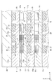
- FIG. 2 is an enlarged cross-sectional view taken along the line II-II in FIG.
- FIG. 3 is an enlarged view of the arrow III in FIG.
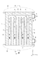
- FIG. 4 is a cross-sectional view taken along line IV-IV in FIG.
- FIG. 5 is a cross-sectional view taken along line VV in FIG.
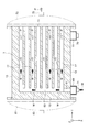
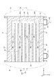
- FIG. 6 is a cross-sectional view for explaining a first modification of the embodiment.
- FIG. 7 is a cross-sectional view for explaining a first modification of the embodiment.
- FIG. 8A is a cross-sectional view for explaining a second modification of the embodiment.
- FIG. 8B is a cross-sectional view for explaining a third modification of the embodiment.
- first fluid is a raw material fluid and the second fluid is a heat medium will be described as an example.
- the types of reaction of the first fluid M include an endothermic reaction due to heating of the first fluid M and an exothermic reaction due to cooling of the first fluid M.
- Examples of the former reaction include, for example, a steam reforming reaction of methane represented by the following chemical formula (1), a dry reforming reaction of methane represented by the following chemical formula (2), and the like.
- Examples of the latter reaction include, for example, a shift reaction represented by the following chemical formula (3), a methanation reaction represented by the following chemical formula (4), and a Fischer-Tropsch (Fischer) represented by the following chemical formula (5). tropsch) synthesis reaction and the like.
- the reaction of the first fluid M is not limited to the steam reforming reaction of methane, etc., but is an acetylation reaction, addition reaction, alkylation reaction, dealkylation reaction, hydrogen dealkylation reaction, reducing alkyl.
- Reaction amination reaction, aromatization reaction, arylation reaction, autothermal reforming reaction, carbonylation reaction, decarbonylation reaction, reductive carbonylation reaction, carboxylation reaction, reductive carboxylation reaction, reducibility Coupling reaction, condensation reaction, cracking reaction, hydrogenolysis reaction, cyclization reaction, cyclo-oligomerization reaction, dehalogenation reaction, dimerization reaction, epoxidation reaction, esterification reaction, exchange reaction, halogenation Reaction, hydrogen halide reaction, homologue formation reaction, hydration reaction, dehydration reaction, hydrogenation reaction, dehydrogenation reaction, hydrogen carboxylation reaction, hydrogen formylation reaction Hydrogenolysis reaction, hydrogenation reaction, hydrosilylation reaction, hydrolysis reaction, hydrotreating reaction, isomerization reaction, methylation reaction, demethylation reaction, substitution reaction, nitration reaction, oxidation reaction, partial oxidation reaction , Polymerization reaction, reduction reaction, reverse water gas shift reaction, sulfonation reaction, short chain polymerization
- a high-temperature gas such as combustion gas, water, a refrigerant, or the like is used, and an appropriate one is selected according to the reaction type and reaction conditions of the first fluid M.
- a high-temperature gas such as a combustion gas
- a high temperature gas or the like is used as the second fluid HC.
- a shift reaction for example, oil, water (including water vapor), molten salt, or the like is used as the second fluid HC.
- reaction of the first fluid M is a methanation reaction, for example, oil, water (including water vapor), molten salt, or the like is used as the second fluid HC.
- reaction of the first fluid M is a Fischer-Tropsch synthesis reaction, for example, water (including water vapor) or the like is used as the second fluid HC.
- the front-rear direction which is the depth direction of the reactor 1 corresponds to the first direction (X direction) described in the claims.
- the left-right direction which is the width direction of the reactor 1 is the second direction (Y direction) described in the claims
- the up-down direction which is the height direction of the reactor 1 is the third direction described in the claims. It corresponds to each direction (Z direction).
- FIG. 2 only a part of the catalyst members and a part of the fins are schematically shown.
- illustration of the catalyst member is omitted.
- illustration of the catalyst member is omitted.
- 8A and 8B illustration of the catalyst member and the fin is omitted.
- each 1st structure 7 and each 2nd structure 9 is as follows.
- the first structure 7 is made of an iron-based alloy such as stainless steel, or a nickel alloy (an example of a heat-resistant alloy) such as Inconel 625, Inconel 617, and Haynesyalloy 230.
- the first structure 7 has a rectangular base plate-like first base plate 11.
- First side walls 13 are respectively provided on the front end side and the rear end side of one side of the first base plate 11 (one side in the thickness direction, which is the upper surface in the present embodiment). Each first side wall 13 protrudes upward (one direction) and extends in the left-right direction.
- a plurality of first intermediate walls 15 are provided at equal intervals in the front-rear direction between the pair of first side walls 13 on one side of the first base plate 11. Each first intermediate wall 15 protrudes upward and extends in the left-right direction. The height of each first intermediate wall 15 is the same as that of the first side wall 13.
- a first flow path 17 through which the first fluid M flows is formed. Yes.
- a plurality of first flow paths 17 are formed at equal intervals in the front-rear direction on one side of the first structure 7, and the first base plate 11 is formed by forming the plurality of first flow paths 17.
- a pair of first side walls 13 and a plurality of first intermediate walls 15 are provided on one side.
- Each first flow path 17 extends in the left-right direction. In the present embodiment, as an example, the length of each first flow path 17 (length in the left-right direction) is set to about 100 cm. Yes.
- the cross-sectional shape of each first flow path 17 is a rectangle. The left end side of each first flow path 17 is opened to introduce the first fluid M.
- a first regulating wall 19 that prevents the second fluid HC from flowing into the plurality of first flow paths 17 is provided.
- the first regulating wall 19 protrudes upward and extends in the front-rear direction so as to connect the pair of first side walls 13.
- the height of the first regulating wall 19 is the same height as the first side wall 13 and the first intermediate wall 15.
- a first outlet 21 for leading out the product P is provided on the right end side of one or both of the first side walls 13.
- the 1st communication flow path 23 which connects the right end side of the several 1st flow path 17 and the 1st outlet 21 is formed in the right end side (1st control wall 19 side) of the single side
- the first communication channel 23 extends in the front-rear direction.
- each first structure 7 is manufactured by cutting a base material made of a single plate, but may be manufactured by performing an etching process. Further, the first base plate 11 may be manufactured by diffusion bonding the pair of first side walls 13, the plurality of first intermediate walls 15, and the first regulating wall 19. Moreover, you may use welding or brazing as another aspect of joining. Each first structure 7 may be manufactured by firing metal powder using a three-dimensional printer. Furthermore, each first structure 7 may be manufactured by combining two or more manufacturing methods of cutting, etching, diffusion bonding, welding, brazing, or firing metal powder.
- the reactor core 3 is schematically illustrated.
- the number of the first structures 7 is several tens, and the number of the first structures 7 in the first structures 7 is as follows.
- the number of one flow path 17 is several tens.
- the number of the first restriction walls 19 and the first communication channel 23 may be changed to a number corresponding to the number of the first channels 17.
- the maximum pressure in the first flow path 17 during the operation of the reactor 1 is set to a predetermined pressure in the range of 0.0 to 20.0 MPaG depending on the type of reaction of the first fluid M and the reaction conditions. ing.
- the second structure 9 is made of the same material as the first structure 7 and has a rectangular base plate-like second base plate 25.
- a second side wall 27 is provided on each of the front end side and the rear end side of one surface (upper surface) of the second base plate 25. Each second side wall 27 protrudes upward and extends in the left-right direction.
- a plurality of second intermediate walls 29 are provided at equal intervals in the front-rear direction between the pair of second side walls 27 on one side of the second base plate 25. Each second intermediate wall 29 protrudes upward and extends in the left-right direction. The height of each second intermediate wall 29 is the same as that of the second side wall 27.
- a second fluid HC that exchanges heat with the first fluid M is circulated between each adjacent second side wall 27 and the second intermediate wall 29 and between each pair of adjacent second intermediate walls 29.
- Second flow paths 31 are respectively formed.
- a plurality of second flow paths 31 are formed at equal intervals in the front-rear direction on one side of the second structure 9, and the second base 31 is formed by forming the plurality of second flow paths 31.
- a pair of second side walls 27 and a plurality of second intermediate walls 29 are provided on one side of the plate 25.
- each second flow path 31 extends in the left-right direction.
- the flow path length (the length in the left-right direction) of each second flow path 31 is about 100 cm.
- each second flow path 31 is a rectangle.
- the right end side of each second flow path 31 is opened to introduce the second fluid HC.
- each 2nd flow path 31 is facing the 1st flow path 17 corresponding on both sides of the 2nd base board 25 or the 1st base board 11, up and down.
- a second restriction wall 33 that prevents the first fluid M from flowing into the plurality of second flow paths 31 is provided.
- the second regulating wall 33 protrudes upward and extends in the front-rear direction so as to connect the pair of second side walls 27.
- the height of the second restriction wall 33 is the same as that of the second side wall 27 and the second intermediate wall 29.
- a second outlet 35 for leading out the second fluid HC is provided on the left end side of one or both of the second side walls 27, a second outlet 35 for leading out the second fluid HC is provided.
- a second communication channel 37 that connects the left end side of the plurality of second channels 31 and the second outlet 35. Is formed.
- the second communication channel 37 extends in the front-rear direction.
- each second structure 9 is manufactured by cutting a base material made of a single plate, but may be manufactured by etching. Moreover, you may manufacture by carrying out the diffusion joining of a pair of 2nd side wall 27, several 2nd intermediate walls 29, and the 2nd control wall 33 to the 2nd base board 25. As another aspect of joining, welding or You may use brazing. Each second structure 9 may be manufactured by firing metal powder using a three-dimensional printer. Further, each second structure 9 may be manufactured by combining two or more manufacturing methods of cutting, etching, diffusion bonding, welding, brazing, or firing metal powder.
- the reactor core 3 is schematically illustrated.
- the number of the second structures 9 is several tens, and each of the second structures 9
- the number of the second flow paths 31 in the body 9 is several tens.
- the number of the second restriction walls 33 and the second communication channels 37 may be changed to a number corresponding to the number of the second channels 31.
- the maximum pressure in the second flow path 31 during the operation of the reactor 1 is set to a predetermined pressure in the range of 0 to 20.0 MPaG depending on the type of reaction of the first fluid M and the reaction conditions. Yes.
- the second structure (uppermost second structure) 9 located on the upper end side has a rectangular plate-like lid structure (cover) covering the plurality of second flow paths 31. Member) 39 is provided.
- the second base plate 25 in the second structure (lowermost second structure) 9 located on the lower end side is the second base in each second structure 9 excluding the lowermost second structure 9. It is thicker than the plate 25.
- Each second structure 9 excluding each first structure 7 and the second structure 9 at the bottom is the same in shape.
- each first side wall 13e of each first side wall 13, the end face 15e of each first intermediate wall 15, and the end face 19e of each first regulating wall 19 are adjacent (adjacent to each first structure 7).
- Diffusion bonding is performed on the lower surface 25 u of the base plate 25.
- the end surface 27e of each second side wall 27, the end surface 29e of each second intermediate wall 29, and the end surface 33e of each second regulating wall 33 are adjacent (adjacent to each second structure 9).
- 11 is diffusion bonded to the lower surface 11u of the cover 11 or the lower surface 39u of the lid structure 39.
- the reactor core 3 in other words, the reactor 1 alternately stacks a predetermined number of first structures 7 corresponding to the reactor capacity and a second structure 9 that is one more than the predetermined number, and A lid structure 39 is disposed on the uppermost second structure 9.
- the reactor 1 is manufactured by simultaneously bonding a plurality of first structures 7, a plurality of second structures 9, and a lid structure 39 in the arrangement state.
- the reactor core 3 (reactor 1) as a whole has a structural strength (pressure strength) and a first strength. This is to further improve the sealing performance for preventing leakage of the fluid M and the like.
- the thickness dimension T3 (refer FIG. 4) of the 1st control wall 19 is set more than the thickness dimension T1 of the 1st side wall 13, and the thickness dimension S3 (refer FIG. 5) of the 2nd control wall 33 is the 1st. It is set to a thickness dimension S1 or more of the two side walls 27.
- the ratio T5 / T4 of the long side dimension T5 to the short side dimension T4 in the cross section of each first flow path 17 is set to 18.0 or less.
- the ratio S5 / S4 of the long side dimension S5 to the short side dimension S4 in the cross section of each second flow path 31 is set to 18.0 or less.
- the reason why the ratio T5 / T4 and the ratio S5 / S4 are set to 18.0 or less is as follows. That is, the bonding area of the end surface 15e of the first intermediate wall 15 and the bonding area of the end surface 29e of the second intermediate wall 29 are more sufficiently secured, and the structural strength (pressure strength) and the sealing performance of each first flow path 17 and the like are increased. This is to increase it.
- the short side dimension T4 in the cross section of the first flow path 17 is synonymous with the depth dimension of the first flow path 17, and the short side dimension S4 in the cross section of the second flow path 31 is This is synonymous with the depth dimension of the second flow path 31.
- the long side dimension T5 in the cross section of the first flow path 17 is synonymous with the width dimension of the first flow path 17, and the long side dimension S5 in the cross section of the second flow path 31 is synonymous with the width dimension of the second flow path 31. It is.
- the ratio T5 / T2 of the width dimension T5 of the first flow path 17 with respect to the thickness dimension T2 of the first intermediate wall 15 is set to 1.0 or more, preferably 2.0 to 4.0.
- the ratio S5 / S2 of the width dimension of the second flow path S5 to the thickness dimension S2 of the second intermediate wall 29 is set to 1.0 or more, preferably 2.0 to 4.0.
- the reason why the ratio T5 / T2 and the ratio S5 / S2 are set to 1.0 or more is to sufficiently form the reaction field of the first fluid M in the first flow path 17.
- the reason why the ratio T5 / T2 and the ratio S5 / S2 are preferably set to 2.0 or more is to form a reaction field of the first fluid M in the first flow path 17 more sufficiently.
- the ratio T5 / T2 and the ratio S5 / S2 are preferably set to 4.0 or less, so that the bonding area of the end surface 15e of the first intermediate wall 15 and the bonding area of the end surface 29e of the second intermediate wall 29 are sufficiently secured. This is because the structural strength (pressure strength) and sealing performance of each first flow path 17 and the like are further increased.
- the width dimension T5 of the first channel 17 and the width dimension S5 of the second channel 31 are set to 2 to 60 mm.
- the ratio T6 / T2 of the thickness dimension (thickness dimension of the first base plate 11) 5 of the first base plate 11 on the bottom side of the first flow path 17 to the thickness dimension T2 of the first intermediate wall 15 is 0.2-5. It is set to 0.
- the ratio S6 / S2 of the thickness dimension (thickness dimension of the second base plate 25) S6 of the second base plate 25 on the bottom side of the second flow path 31 with respect to the width dimension S2 of the second intermediate wall 29 is 0. It is set to 2 to 5.0.
- the ratio T6 / T2 and the ratio S6 / S2 are set to 0.2 or more because the rigidity of the first base plate 11 and the rigidity of the second base plate 25 are more sufficiently ensured.
- the ratio T6 / T2 and the ratio S6 / S2 are set to 5.0 or less because the distance between each first flow path 17 and the corresponding second flow path 31 is shortened, This is because the heat transfer efficiency between the fluid M and the second fluid HC in the corresponding second flow path 31 is increased.
- the thickness dimension S1 of the second side wall 27 is set to be the same as the thickness dimension T1 of the first side wall 13, and the thickness dimension S2 of the second intermediate wall 29 is the same as the thickness dimension T2 of the first intermediate wall 15.
- Is set to The thickness dimension S3 of the second restriction wall 33 is set to be the same as the thickness dimension T3 of the first restriction wall 19.
- the reaction of the first fluid M is a steam reforming reaction of methane
- Ni nickel
- Pt platinum
- Ru ruthenium
- Rh rhodium
- Pd palladium
- Co cobalt
- One or a plurality of metals selected from the group consisting of rhenium (Re) and iridium (Ir) are used as the catalyst.
- a catalyst may be applied (an example of support) in each first flow path 17.
- a pair of fins (baffles) 43 are detachably provided in each second flow path 31.
- the pair of fins 43 are stacked one above the other.
- Each fin 43 is made of, for example, stainless steel and extends in the left-right direction.
- the cross section of each fin 43 has a wave shape.
- a dome-shaped first introduction chamber (an example of a hollow first introduction member) for introducing the first fluid M into each first flow path 17. ) 45 is detachably provided.
- the inside of the first introduction chamber 45 communicates with each first flow path 17.
- the first introduction chamber 45 is provided with a raw material supply port 47.
- the raw material supply port 47 is connected to a raw material supply source (not shown) that supplies the first fluid M.
- a box-shaped first discharge chamber for collecting and discharging the products P derived from the respective first outlets 21 is provided. 49) is provided.
- the first discharge chamber 49 extends in the vertical direction, and the inside of the first discharge chamber 49 communicates with each first outlet 21.
- a product discharge port 51 is provided at the center, end, upper part, or lower part of the first discharge chamber 49.
- the product discharge port 51 is connected to another processor (not shown) that performs post-processing and the like on the product P.
- a dome-shaped second introduction chamber (an example of a hollow second introduction member) for introducing a second fluid into each second flow path 31. ) 53 is detachably provided on the right side of the reactor core 3.
- the inside of the second introduction chamber 53 communicates with each second flow path 31.
- the second introduction chamber 53 is provided with a heat medium supply port 55.
- the heat medium supply port 55 is connected to a heat medium supply source (not shown) that supplies the second fluid HC.
- the first fluid M By supplying the first fluid M from the raw material supply source to the first introduction chamber 45 (reactor core 3 side) via the raw material supply port 47, the first fluid M is introduced into the first flow paths 17, It distribute
- first fluid M in each first flow path 17 and the second fluid HC in the corresponding second flow path 31 heat exchange is performed between the first fluid M in each first flow path 17 and the second fluid HC in the corresponding second flow path 31, and the first fluid M can be heated or cooled.
- the first fluid M can be reacted (endothermic reaction or exothermic reaction) to generate the product P.
- the generated product P is led out from each first outlet 21 into the first discharge chamber 49 and discharged from the product discharge port 51 to another processor side.
- the second fluid HC that has contributed to the heat exchange is led out from each second outlet 35 into the second discharge chamber 57 and discharged from the heat medium discharge port 59 to the heat medium collector.
- each first side wall 13 and the end surface 15e of each first intermediate wall 15 are diffusion bonded to the lower surface 25u of the adjacent second base plate 25, the structural strength (pressure resistance strength) is provided for each first flow path 17. ) And a sealing property that prevents leakage of the first fluid M and the like can be secured (guaranteed). Further, the end surface 27e of each second side wall 27, the end surface 29e of each second intermediate wall 29, and the like are diffusion bonded to the lower surface 11u of the first base plate 11 or the lower surface 39u of the lid structure 39. Therefore, it is possible to ensure (guarantee) the structural strength (pressure strength) and the sealing performance for preventing the second fluid HC from leaking for each second flow path 31.
- the ratio T5 / T4 and the ratio S5 / S4 are respectively set to 18.0 or less, the bonding area of the end surface 15e of the first intermediate wall 15 is more sufficiently secured, and the first flow paths 17 and the like.
- the structural strength (pressure strength) and the sealing property can be further increased.
- the ratio T6 / T2 and the ratio S6 / S2 are set to 0.2 to 5.0, the rigidity and the like of the first base plate 11 is more sufficiently secured, The heat transfer efficiency between the first fluid M and the corresponding second fluid HC in the second flow path 31 can be further increased.
- a first communication channel 23 is formed on the left end side of one surface of the first base plate 11.
- a first communication channel 63 that communicates the first introduction port 61 and the left ends of the plurality of first channels 17 is provided on the left end side of one surface of the first base plate 11. Is formed.
- the first communication channel 63 extends in the front-rear direction.
Landscapes
- Chemical & Material Sciences (AREA)
- Chemical Kinetics & Catalysis (AREA)
- Organic Chemistry (AREA)
- Engineering & Computer Science (AREA)
- Physics & Mathematics (AREA)
- Thermal Sciences (AREA)
- Mechanical Engineering (AREA)
- General Engineering & Computer Science (AREA)
- General Health & Medical Sciences (AREA)
- Combustion & Propulsion (AREA)
- Inorganic Chemistry (AREA)
- Health & Medical Sciences (AREA)
- Fluid Mechanics (AREA)
- General Chemical & Material Sciences (AREA)
- Oil, Petroleum & Natural Gas (AREA)
- Physical Or Chemical Processes And Apparatus (AREA)
- Heat-Exchange Devices With Radiators And Conduit Assemblies (AREA)
- Steering Control In Accordance With Driving Conditions (AREA)
Abstract
Description
CH4 + CO2 → 2H2 + 2CO ・・・化学式(2)
後者の反応(発熱反応)の例としては、例えば、後記の化学式(3)に示すシフト反応、後記の化学式(4)に示すメタネーション反応、後記の化学式(5)に示すフィッシャー-トロプシュ(Fischer tropsch)合成反応等が挙げられる。
CO + 3H2 → CH4 + H2O ・・・化学式(4)
(2n+1)H2 + nCO → CnH2n+2 + nH2O ・・・化学式(5)
なお、第一流体Mの反応は、メタンの水蒸気改質反応等に限定されるものでなく、アセチル化反応、付加反応、アルキル化反応、脱アルキル化反応、水素脱アルキル化反応、還元性アルキル化反応、アミン化反応、芳香族化反応、アリール化反応、自熱式改質反応、カルボニル化反応、脱カルボニル化反応、還元性カルボニル化反応、カルボキシル化反応、還元性カルボキシル化反応、還元性カップリング反応、縮合反応、分解(クラッキング)反応、水素分解反応、環化反応、シクロオリゴマー化反応、脱ハロゲン化反応、二量体化反応、エポキシ化反応、エステル化反応、交換反応、ハロゲン化反応、水素ハロゲン化反応、同族体形成反応、水和反応、脱水反応、水素化反応、脱水素化反応、水素カルボキシル化反応、水素ホルミル化反応、水添分解反応、水素金属化反応、ヒドロシリル化反応、加水分解反応、水素化処理反応、異性体化反応、メチル化反応、脱メチル化反応、置換反応、ニトロ化反応、酸化反応、部分酸化反応、重合反応、還元反応、逆水性ガスシフト反応、スルホン化反応、短鎖重合反応、エステル交換反応、及び三量体化反応であっても構わない。
本実施形態の変形例1について図6及び図7を参照して説明する。
本実施形態の変形例2について、図8Aを参照して説明する。
本実施形態の変形例3について、図8Bを参照して説明する。
Claims (17)
- 第一流体と第二流体との間の熱交換によって、第一流体を反応させて、生成物を生成するリアクタであって、
板状の一ベース板の片面における第一方向の両端側にそれぞれ設けられかつ前記第一方向に直交する第二方向へ延びた第一側壁、及び前記第一ベース板の片面における一対の前記第一側壁の間に前記第一方向に沿って間隔を置いて設けられかつ前記第二方向へ延びた複数の第一中間壁を有し、各隣接する前記第一側壁と前記第一中間壁の間、及び各隣接する一対の前記第一中間壁の間に、第一流体を流通させる第一流路がそれぞれ形成された複数の第一構造体と、
前記第一方向と前記第二方向に直交する第三方向に沿って複数の前記第一構造体と混在して積層され、板状の第二ベース板の片面における前記第一方向の両端側にそれぞれ設けられかつ前記第二方向へ延びた第二側壁、及び前記第二ベース板の片面における一対の前記第二側壁の間に前記第一方向に沿って間隔を置いて設けられかつ前記第二方向へ延びた複数の第二中間壁を有し、各隣接する前記第二側壁と前記第二中間壁の間、及び各隣接する一対の前記第二中間壁の間に、第二流体を流通させる第二流路がそれぞれ形成された複数の第二構造体と、
前記第三方向の一端側に位置する前記第二構造体に設けられ、複数の前記第二流路を覆う蓋構造体と、を具備し、
各第一側壁の端面及び各第一中間壁の端面は、隣接する前記第二構造体に接合され、
各第二側壁の端面及び各第二中間壁の端面は、隣接する前記第一構造体又は前記蓋構造体に接合され、
前記第一側壁の厚み寸法は、前記第一中間壁の厚み寸法以上に設定され、
前記第二側壁の厚み寸法は、前記第二中間壁の厚み寸法以上に設定されているリアクタ。 - リアクタ容量に応じた所定数の前記第一構造体と、複数の前記第二構造体とを混在して積層し、かつ前記第三方向の一端側に位置する前記第二構造体に前記蓋構造体を配置した状態で、複数の前記第一構造体、複数の前記第二構造体、及び前記蓋構造体を同時に接合することによって製作されている、請求項1に記載のリアクタ。
- 複数の前記第一構造体及び複数の前記第二構造体は、前記第三方向に沿って交互に積層されている、請求項1又は請求項2に記載のリアクタ。
- 前記第一中間壁の厚み寸法に対する前記第一側壁の厚み寸法の比率、及び前記第二中間壁の厚み寸法に対する前記第二側壁の厚み寸法の比率は、4.0以上にそれぞれ設定されている、請求項1から請求項3のうちのいずれか1項に記載のリアクタ。
- 各第一流路の断面形状及び各第二流路の断面形状は、それぞれ矩形であって、各第一流路の断面における短辺寸法に対する長辺寸法の比率、及び各第二流路の断面における短辺寸法に対する長辺寸法の比率は、18.0以下にそれぞれ設定されている、請求項1から請求項4のうちのいずれか1項に記載のリアクタ。
- 前記第一中間壁の厚さ寸法に対する前記第一流路の幅寸法の比率、及び前記第二中間壁の厚さ寸法に対する前記第二流路の幅寸法の比率は、1.0以上にそれぞれ設定されている、請求項1から請求項5のうちのいずれか1項に記載のリアクタ。
- 前記第一中間壁の厚み寸法に対する第一流路の底部側の前記第一ベース板の厚み寸法の比率、及び前記第二中間壁の厚み寸法に対する第二流路の底部側の前記第二ベース板の厚み寸法の比率は、0.2~5.0にそれぞれ設定されている、請求項1から請求項6のうちのいずれか1項に記載のリアクタ。
- 前記第二側壁の厚み寸法は、前記第一側壁の厚み寸法と同じに設定され、前記第二中間壁の厚み寸法は、前記第一中間壁の厚み寸法と同じに設定されている、請求項1から請求項7のうちのいずれか1項に記載のリアクタ。
- 各第一流路内に、第一流体の反応を促進する触媒が担持されている、請求項1から請求項8のうちのいずれか1項に記載のリアクタ。
- 各第一流路内に、前記触媒を担持した触媒部材が着脱可能に設けられている、請求項9に記載のリアクタ。
- 各第二流路内に、フィンが着脱可能に設けられている、請求項1から請求項10のうちのいずれか1項に記載のリアクタ。
- 各第一ベース板の片面の前記第二方向の他端側に、複数の前記第一流路内への第二流体の流入を阻止する第一規制壁が設けられ、各第一構造体における少なくともいずれかの前記第一側壁の前記第二方向の他端側に、生成物を導出するための第一導出口が設けられ、各第一構造体の片面における前記第二方向の他端側に、複数の前記第一流路の前記第二方向の他端側と前記第一導出口を連絡する第一連絡流路が形成され、
各第二ベース板の片面の前記第二方向の一端側に、複数の前記第二流路内への第一流体の流入を阻止する第二規制壁が設けられ、各第二構造体における少なくともいずれかの前記第二側壁の前記第二方向の一端側に、第二流体を導出するための第二導出口が設けられ、各第二構造体の片面における前記第二方向の一端側に、複数の前記第二流路の前記第二方向の一端側と前記第二導出口を連絡する第二連絡流路が形成され、
各第一規制壁の端面は、隣接する前記第二構造体又は前記第一構造体に接合され、
各第二規制壁の端面は、隣接する前記第一構造体、前記第二構造体、又は前記蓋構造体に接合されている、請求項1から請求項11のうちのいずれか1項に記載のリアクタ。 - 複数の前記第一構造体と複数の前記第二構造体を混在して積層してなるリアクタコアの前記第二方向の一方側に着脱可能に設けられ、各第一流路内に第一流体を導入するための中空状の第一分配流路と、
前記リアクタコアに設けられ、各第一導出口から導出した生成物を集合して排出するための中空状の第一排出部材と、
前記リアクタコアの前記第二方向の他方側に着脱可能に設けられ、各第二流路内に第二流体を導入するための中空状の第二導入部材と、
前記リアクタコアに設けられ、各第二導出口から導出した第二流体を集合して排出するための中空状の第二排出部材と、を具備している、請求項12に記載のリアクタ。 - 各第一ベース板の片面における前記第二方向の一端側に、複数の前記第一流路内への第二流体の流入を阻止する第一規制壁が設けられ、各第一構造体における少なくともいずれかの前記第一側壁における前記第二方向の一端側に、第一流体を導入するための第一導入口が設けられ、各第一構造体の片面における前記第二方向の一端側に、前記第一導入口と複数の前記第一流路の前記第二方向の一端側を連絡する第一連絡流路が形成され、
各第二ベース板の片面における前記第二方向の他端側に、複数の前記第二流路内への第一流体の流入を阻止する第二規制壁が設けられ、各第二構造体における少なくともいずれかの前記第二側壁における前記第二方向の他端側に、第二流体を導入するための第二導入口が設けられ、各第二構造体の片面における前記第二方向の他端側に、前記第二導入口と複数の前記第二流路の前記第二方向の他端側を連絡する第二連絡流路が形成され、
各第一規制壁の端面は、隣接する前記第二構造体又は前記第一構造体に接合され、
各第二規制壁の端面は、隣接する前記第一構造体、前記第二構造体、又は前記蓋構造体に接合されている、請求項1から請求項11のうちのいずれか1項に記載のリアクタ。 - 複数の前記第一構造体と複数の前記第二構造体を混在して積層してなるリアクタコアに設けられ、各第一導入口から各第一流路内に第一流体を導入するための中空状の第一導入部材と、
前記リアクタコアの前記第二方向の他方側に着脱可能に設けられ、各第一流路内から導出した生成物を集合して排出するための中空状の第一排出部材と、
前記リアクタコアに設けられ、各第二導入口から各第二流路内に第二流体を導入するための中空状の第二導入部材と、
前記リアクタコアの前記第二方向の一方側に着脱可能に設けられ、各第二構造体から導出した第二流体を集合して排出するための中空状の第二排出部材と、を具備している、請求項14に記載のリアクタ。 - 各第一側壁の端面、各第一中間壁の端面の接合、及び各第一規制壁の端面の接合は、それぞれ拡散接合であって、各第二側壁の端面、各第二中間壁の端面、及び各第二規制壁の端面の接合は、それぞれ拡散接合である、請求項12から請求項15のうちのいずれか1項に記載のリアクタ。
- 運転中における前記第一流路内及び前記第二流路内の最大圧力は、0.0~20.0MPaGに設定されている、請求項1から請求項16のうちのいずれか1項に記載のリアクタ。
Priority Applications (9)
| Application Number | Priority Date | Filing Date | Title |
|---|---|---|---|
| EP16807496.1A EP3305401B1 (en) | 2015-06-08 | 2016-06-08 | Reactor |
| MYPI2017704379A MY187959A (en) | 2015-06-08 | 2016-06-08 | Reactor |
| CN201680029517.0A CN107614098B (zh) | 2015-06-08 | 2016-06-08 | 反应器 |
| SG11201709564VA SG11201709564VA (en) | 2015-06-08 | 2016-06-08 | Reactor |
| KR1020177035379A KR20180004251A (ko) | 2015-06-08 | 2016-06-08 | 리액터 |
| KR1020207002643A KR102223166B1 (ko) | 2015-06-08 | 2016-06-08 | 리액터 |
| CA2987457A CA2987457C (en) | 2015-06-08 | 2016-06-08 | Multilayer reactor utilizing heat exchange |
| JP2017523659A JP6604380B2 (ja) | 2015-06-08 | 2016-06-08 | リアクタ |
| US15/820,548 US10118148B2 (en) | 2015-06-08 | 2017-11-22 | Reactor |
Applications Claiming Priority (2)
| Application Number | Priority Date | Filing Date | Title |
|---|---|---|---|
| JP2015-115659 | 2015-06-08 | ||
| JP2015115659 | 2015-06-08 |
Related Child Applications (1)
| Application Number | Title | Priority Date | Filing Date |
|---|---|---|---|
| US15/820,548 Continuation US10118148B2 (en) | 2015-06-08 | 2017-11-22 | Reactor |
Publications (1)
| Publication Number | Publication Date |
|---|---|
| WO2016199790A1 true WO2016199790A1 (ja) | 2016-12-15 |
Family
ID=57503895
Family Applications (1)
| Application Number | Title | Priority Date | Filing Date |
|---|---|---|---|
| PCT/JP2016/066992 Ceased WO2016199790A1 (ja) | 2015-06-08 | 2016-06-08 | リアクタ |
Country Status (10)
| Country | Link |
|---|---|
| US (1) | US10118148B2 (ja) |
| EP (1) | EP3305401B1 (ja) |
| JP (1) | JP6604380B2 (ja) |
| KR (2) | KR20180004251A (ja) |
| CN (1) | CN107614098B (ja) |
| CA (1) | CA2987457C (ja) |
| MY (1) | MY187959A (ja) |
| SG (1) | SG11201709564VA (ja) |
| TW (1) | TWI613007B (ja) |
| WO (1) | WO2016199790A1 (ja) |
Cited By (2)
| Publication number | Priority date | Publication date | Assignee | Title |
|---|---|---|---|---|
| WO2018181651A1 (ja) * | 2017-03-31 | 2018-10-04 | 株式会社Ihi | 熱処理装置 |
| JP2019198830A (ja) * | 2018-05-17 | 2019-11-21 | 株式会社Ihi | 反応装置 |
Families Citing this family (3)
| Publication number | Priority date | Publication date | Assignee | Title |
|---|---|---|---|---|
| JP6728781B2 (ja) * | 2016-03-03 | 2020-07-22 | 株式会社Ihi | 反応装置 |
| CA3151305A1 (en) * | 2019-11-13 | 2021-05-20 | Yusuke Takeuchi | Jig for inserting filling member into reactor |
| US11774189B2 (en) * | 2020-09-29 | 2023-10-03 | Air Products And Chemicals, Inc. | Heat exchanger, hardway fin arrangement for a heat exchanger, and methods relating to same |
Citations (5)
| Publication number | Priority date | Publication date | Assignee | Title |
|---|---|---|---|---|
| JPS5810583U (ja) * | 1981-07-13 | 1983-01-24 | 住友精密工業株式会社 | 熱交換器 |
| JPH06111838A (ja) * | 1992-09-30 | 1994-04-22 | Toshiba Corp | 改質器、改質システム、及び燃料電池システム |
| JP2006336873A (ja) * | 2002-10-02 | 2006-12-14 | Showa Denko Kk | 熱交換器用チューブ及び熱交換器 |
| JP2008518184A (ja) * | 2004-10-11 | 2008-05-29 | コリア・インスティチュート・オブ・エネルギー・リサーチ | 均一加熱のための微細流路加熱器 |
| WO2015037597A1 (ja) * | 2013-09-13 | 2015-03-19 | 株式会社Ihi | リアクタ |
Family Cites Families (30)
| Publication number | Priority date | Publication date | Assignee | Title |
|---|---|---|---|---|
| GB395709A (en) * | 1931-09-12 | 1933-07-12 | Robert Arthur Carleton | Improvements in or relating to electric fluid heating apparatus |
| US5209906A (en) * | 1991-05-10 | 1993-05-11 | Her Majesty The Queen In Right Of Canada, As Represented By The Minister Of National Defence | Modular isothermal reactor |
| JPH06345405A (ja) | 1993-06-11 | 1994-12-20 | Tokyo Gas Co Ltd | 水素製造装置 |
| EP1153653A1 (en) * | 2000-05-11 | 2001-11-14 | Methanol Casale S.A. | Reactor for exothermic or endothermic heterogeneous reactions |
| ZA200306075B (en) | 2001-02-16 | 2004-09-08 | Battelle Memorial Institute | Integrated reactors, methods of making same, and methods of conducting simultaneous exothermic and endothermic reactions. |
| EP1434652B1 (en) * | 2001-10-12 | 2005-02-16 | GTL Microsystems AG | Catalytic reactor |
| JP2003183003A (ja) | 2001-12-13 | 2003-07-03 | Sanyo Electric Co Ltd | 多管式反応器 |
| US7883670B2 (en) | 2002-02-14 | 2011-02-08 | Battelle Memorial Institute | Methods of making devices by stacking sheets and processes of conducting unit operations using such devices |
| AU2003272090B2 (en) * | 2002-10-02 | 2008-08-07 | Showa Denko K.K. | Heat exchanging tube and heat exchanger |
| US7405338B2 (en) * | 2003-04-07 | 2008-07-29 | Velocys | Dehydrogenation reactions in narrow reaction chambers and integrated reactors |
| US7220390B2 (en) | 2003-05-16 | 2007-05-22 | Velocys, Inc. | Microchannel with internal fin support for catalyst or sorption medium |
| US8580211B2 (en) | 2003-05-16 | 2013-11-12 | Velocys, Inc. | Microchannel with internal fin support for catalyst or sorption medium |
| GB0408896D0 (en) * | 2004-04-20 | 2004-05-26 | Accentus Plc | Catalytic reactor |
| WO2005108899A1 (en) * | 2004-05-11 | 2005-11-17 | Showa Denko K.K. | Heat exchangers |
| GB0500838D0 (en) | 2005-01-15 | 2005-02-23 | Accentus Plc | Catalytic reactor |
| JP4963372B2 (ja) | 2006-04-10 | 2012-06-27 | 株式会社豊田中央研究所 | 反応器、反応器の製造方法、及び反応器用単位部材 |
| JP4809113B2 (ja) * | 2006-04-24 | 2011-11-09 | 株式会社豊田中央研究所 | 熱交換型改質器 |
| JP6009732B2 (ja) | 2007-07-05 | 2016-10-19 | サウディ ベーシック インダストリーズ コーポレイション | 吸熱反応を行うプロセス |
| KR101502647B1 (ko) * | 2008-03-14 | 2015-03-13 | 디아이씨 가부시끼가이샤 | 우레탄(메트)아크릴레이트의 제조 방법 |
| US8569023B2 (en) * | 2008-03-28 | 2013-10-29 | The Regents Of The University Of California | Producing dicarboxylic acids using polyketide synthases |
| GB0918738D0 (en) | 2009-10-26 | 2009-12-09 | Compactgtl Plc | Reactor with channels |
| KR101973576B1 (ko) | 2010-03-02 | 2019-04-29 | 벨로시스, 인코포레이티드 | 용접, 라미네이트식 장치 및 이의 제조 방법과, 상기 장치의 사용 방법 |
| JP2014084334A (ja) | 2012-10-19 | 2014-05-12 | Dic Corp | 重合体の製造方法 |
| JPWO2014208444A1 (ja) * | 2013-06-26 | 2017-02-23 | 株式会社Ihi | 触媒構造体、リアクタ、および、触媒構造体の製造方法 |
| EP3015164B1 (en) * | 2013-06-27 | 2022-02-23 | IHI Corporation | Reactor with corrugated catalyst structure |
| CN107614099B (zh) * | 2015-06-08 | 2020-03-06 | 株式会社Ihi | 反应器 |
| DE102015210919A1 (de) * | 2015-06-15 | 2016-12-15 | Fraunhofer-Gesellschaft zur Förderung der angewandten Forschung e.V. | MEMS-Wandler zum Interagieren mit einem Volumenstrom eines Fluids und Verfahren zum Herstellen desselben |
| JP6728739B2 (ja) * | 2016-02-12 | 2020-07-22 | 株式会社Ihi | 反応装置 |
| JP6728751B2 (ja) * | 2016-02-23 | 2020-07-22 | 株式会社Ihi | 反応装置及び反応システム |
| JP6794769B2 (ja) * | 2016-10-21 | 2020-12-02 | 富士通株式会社 | 情報処理装置 |
-
2016
- 2016-06-08 KR KR1020177035379A patent/KR20180004251A/ko not_active Ceased
- 2016-06-08 WO PCT/JP2016/066992 patent/WO2016199790A1/ja not_active Ceased
- 2016-06-08 CA CA2987457A patent/CA2987457C/en active Active
- 2016-06-08 CN CN201680029517.0A patent/CN107614098B/zh active Active
- 2016-06-08 KR KR1020207002643A patent/KR102223166B1/ko active Active
- 2016-06-08 SG SG11201709564VA patent/SG11201709564VA/en unknown
- 2016-06-08 EP EP16807496.1A patent/EP3305401B1/en active Active
- 2016-06-08 TW TW105118227A patent/TWI613007B/zh active
- 2016-06-08 JP JP2017523659A patent/JP6604380B2/ja active Active
- 2016-06-08 MY MYPI2017704379A patent/MY187959A/en unknown
-
2017
- 2017-11-22 US US15/820,548 patent/US10118148B2/en active Active
Patent Citations (5)
| Publication number | Priority date | Publication date | Assignee | Title |
|---|---|---|---|---|
| JPS5810583U (ja) * | 1981-07-13 | 1983-01-24 | 住友精密工業株式会社 | 熱交換器 |
| JPH06111838A (ja) * | 1992-09-30 | 1994-04-22 | Toshiba Corp | 改質器、改質システム、及び燃料電池システム |
| JP2006336873A (ja) * | 2002-10-02 | 2006-12-14 | Showa Denko Kk | 熱交換器用チューブ及び熱交換器 |
| JP2008518184A (ja) * | 2004-10-11 | 2008-05-29 | コリア・インスティチュート・オブ・エネルギー・リサーチ | 均一加熱のための微細流路加熱器 |
| WO2015037597A1 (ja) * | 2013-09-13 | 2015-03-19 | 株式会社Ihi | リアクタ |
Non-Patent Citations (1)
| Title |
|---|
| See also references of EP3305401A4 * |
Cited By (10)
| Publication number | Priority date | Publication date | Assignee | Title |
|---|---|---|---|---|
| WO2018181651A1 (ja) * | 2017-03-31 | 2018-10-04 | 株式会社Ihi | 熱処理装置 |
| JP2018171590A (ja) * | 2017-03-31 | 2018-11-08 | 株式会社Ihi | 熱処理装置 |
| CN110461464A (zh) * | 2017-03-31 | 2019-11-15 | 株式会社Ihi | 热处理装置 |
| EP3603793A4 (en) * | 2017-03-31 | 2020-12-23 | IHI Corporation | HEAT TREATMENT DEVICE |
| CN110461464B (zh) * | 2017-03-31 | 2021-12-24 | 株式会社Ihi | 热处理装置 |
| US11378343B2 (en) | 2017-03-31 | 2022-07-05 | Ihi Corporation | Heat treatment device |
| JP2019198830A (ja) * | 2018-05-17 | 2019-11-21 | 株式会社Ihi | 反応装置 |
| WO2019221238A1 (ja) | 2018-05-17 | 2019-11-21 | 株式会社Ihi | 反応装置 |
| US11413598B2 (en) | 2018-05-17 | 2022-08-16 | Ihi Corporation | Reactor |
| JP7271865B2 (ja) | 2018-05-17 | 2023-05-12 | 株式会社Ihi | 反応装置 |
Also Published As
| Publication number | Publication date |
|---|---|
| EP3305401A4 (en) | 2018-12-26 |
| TW201711867A (zh) | 2017-04-01 |
| US10118148B2 (en) | 2018-11-06 |
| JPWO2016199790A1 (ja) | 2018-03-29 |
| JP6604380B2 (ja) | 2019-11-13 |
| SG11201709564VA (en) | 2017-12-28 |
| EP3305401A1 (en) | 2018-04-11 |
| KR20180004251A (ko) | 2018-01-10 |
| KR102223166B1 (ko) | 2021-03-03 |
| CA2987457A1 (en) | 2016-12-15 |
| US20180093241A1 (en) | 2018-04-05 |
| CN107614098B (zh) | 2020-08-11 |
| EP3305401B1 (en) | 2023-12-20 |
| TWI613007B (zh) | 2018-02-01 |
| CN107614098A (zh) | 2018-01-19 |
| KR20200011620A (ko) | 2020-02-03 |
| CA2987457C (en) | 2020-04-07 |
| MY187959A (en) | 2021-11-01 |
Similar Documents
| Publication | Publication Date | Title |
|---|---|---|
| JP6604380B2 (ja) | リアクタ | |
| JP6439326B2 (ja) | リアクタ | |
| CA2899697C (en) | Catalytic reactor | |
| JP6696505B2 (ja) | リアクタ | |
| JP6387585B2 (ja) | リアクタ | |
| JP7263833B2 (ja) | 熱交換構造 | |
| WO2022024309A1 (ja) | 熱交換構造 | |
| JP7271865B2 (ja) | 反応装置 | |
| JP7107387B2 (ja) | 反応装置 |
Legal Events
| Date | Code | Title | Description |
|---|---|---|---|
| 121 | Ep: the epo has been informed by wipo that ep was designated in this application |
Ref document number: 16807496 Country of ref document: EP Kind code of ref document: A1 |
|
| ENP | Entry into the national phase |
Ref document number: 2017523659 Country of ref document: JP Kind code of ref document: A |
|
| ENP | Entry into the national phase |
Ref document number: 2987457 Country of ref document: CA |
|
| WWE | Wipo information: entry into national phase |
Ref document number: 11201709564V Country of ref document: SG |
|
| ENP | Entry into the national phase |
Ref document number: 20177035379 Country of ref document: KR Kind code of ref document: A |
|
| NENP | Non-entry into the national phase |
Ref country code: DE |
|
| WWE | Wipo information: entry into national phase |
Ref document number: 2016807496 Country of ref document: EP |