WO2016199704A1 - 画像形成装置および画像形成システム - Google Patents
画像形成装置および画像形成システム Download PDFInfo
- Publication number
- WO2016199704A1 WO2016199704A1 PCT/JP2016/066709 JP2016066709W WO2016199704A1 WO 2016199704 A1 WO2016199704 A1 WO 2016199704A1 JP 2016066709 W JP2016066709 W JP 2016066709W WO 2016199704 A1 WO2016199704 A1 WO 2016199704A1
- Authority
- WO
- WIPO (PCT)
- Prior art keywords
- image
- gradation
- print image
- image information
- Prior art date
- Legal status (The legal status is an assumption and is not a legal conclusion. Google has not performed a legal analysis and makes no representation as to the accuracy of the status listed.)
- Ceased
Links
Images








Classifications
-
- B—PERFORMING OPERATIONS; TRANSPORTING
- B41—PRINTING; LINING MACHINES; TYPEWRITERS; STAMPS
- B41J—TYPEWRITERS; SELECTIVE PRINTING MECHANISMS, i.e. MECHANISMS PRINTING OTHERWISE THAN FROM A FORME; CORRECTION OF TYPOGRAPHICAL ERRORS
- B41J2/00—Typewriters or selective printing mechanisms characterised by the printing or marking process for which they are designed
- B41J2/525—Arrangement for multi-colour printing, not covered by group B41J2/21, e.g. applicable to two or more kinds of printing or marking process
-
- B—PERFORMING OPERATIONS; TRANSPORTING
- B41—PRINTING; LINING MACHINES; TYPEWRITERS; STAMPS
- B41J—TYPEWRITERS; SELECTIVE PRINTING MECHANISMS, i.e. MECHANISMS PRINTING OTHERWISE THAN FROM A FORME; CORRECTION OF TYPOGRAPHICAL ERRORS
- B41J5/00—Devices or arrangements for controlling character selection
- B41J5/30—Character or syllable selection controlled by recorded information
-
- G—PHYSICS
- G06—COMPUTING OR CALCULATING; COUNTING
- G06F—ELECTRIC DIGITAL DATA PROCESSING
- G06F3/00—Input arrangements for transferring data to be processed into a form capable of being handled by the computer; Output arrangements for transferring data from processing unit to output unit, e.g. interface arrangements
- G06F3/12—Digital output to print unit, e.g. line printer, chain printer
-
- H—ELECTRICITY
- H04—ELECTRIC COMMUNICATION TECHNIQUE
- H04N—PICTORIAL COMMUNICATION, e.g. TELEVISION
- H04N1/00—Scanning, transmission or reproduction of documents or the like, e.g. facsimile transmission; Details thereof
- H04N1/46—Colour picture communication systems
-
- H—ELECTRICITY
- H04—ELECTRIC COMMUNICATION TECHNIQUE
- H04N—PICTORIAL COMMUNICATION, e.g. TELEVISION
- H04N1/00—Scanning, transmission or reproduction of documents or the like, e.g. facsimile transmission; Details thereof
- H04N1/46—Colour picture communication systems
- H04N1/56—Processing of colour picture signals
- H04N1/60—Colour correction or control
Definitions
- the present invention relates to an image forming apparatus and an image forming system for reproducing a luminance gradation in an input image in a printed image.
- CT Computer Tomography
- MRI Magnetic Resonance Imaging
- CR Computer Recimulation
- FPD Freque Panel Detector
- ultrasonic diagnostic devices are used as digital image generation devices.
- image display device such as a CRT (Cathode Ray Tube) or output as a print image by an image forming device such as a printer are used.
- the conventional method has a problem that all process colors need to be used.
- an object of the present invention is to provide an image forming apparatus and an image forming system that can reduce the types of process colors to be used.
- the image forming apparatus of the present invention includes: a print image information generation unit that generates print image information for a print image based on an input image; and the print image information generated by the print image information generation unit.
- a print execution unit for outputting an image wherein the print image information generation unit converts the luminance gradation in the input image into a lightness gradation in a single hue expressed by two or more process colors. Then, the print image information is generated.
- the image forming apparatus of the present invention converts the luminance gradation in the input image into the lightness gradation in a single hue to generate print image information. Therefore, the print image is generated according to the print image information. It is possible to prevent all process colors from being used when output. Therefore, the image forming apparatus of the present invention can reduce the types of process colors used.
- the image forming system of the present invention includes a print image information generation unit that generates print image information for a print image based on an input image, and the print image information generated by the print image information generation unit.
- a print execution unit for outputting an image wherein the print image information generation unit converts the luminance gradation in the input image into a lightness gradation in a single hue expressed by two or more process colors. Then, the print image information is generated.
- the image forming system of the present invention generates the print image information by converting the luminance gradation in the input image into the lightness gradation in a single hue, so that the print image is generated according to the print image information. It is possible to prevent all process colors from being used when output. Therefore, the image forming system of the present invention can reduce the types of process colors used.
- the image forming apparatus and the image forming system of the present invention can reduce the types of process colors to be used.
- FIG. 1 is a block diagram of an image forming system according to a first embodiment of the present invention.
- FIG. 2 is a block diagram of the MFP shown in FIG. 1.
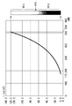
- FIG. 3 is a diagram showing a relationship between luminance reproducible on a recording medium by the MFP shown in FIG. 2 and a discrimination threshold.
- FIG. 4 is a diagram showing a relationship between a luminance based on GSDF defined by DICOM and a discrimination threshold, and is a diagram based on the diagram shown in FIG. 3.
- FIG. 2 is a block diagram of the print instruction apparatus shown in FIG. 1.
- 3 is a flowchart of the operation of the MFP shown in FIG. 2 when performing calibration.
- 3 is a flowchart of the operation of the MFP shown in FIG.
- FIG. 3 is a diagram showing a hue circle in an L * a * b * color space for the MFP shown in FIG. 2.
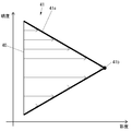
- FIG. 9 is a diagram illustrating the cyan equi-hue surface shown in FIG. 8 when the luminance gradation in the input image is converted into the lightness gradation in the cyan hue. It is a figure which shows the pure color and the clear color in the cyan equal hue surface shown in FIG.
- FIG. 3 is a diagram showing a relationship between luminance reproducible on a recording medium by the MFP shown in FIG. 2 and pure colors and clear colors on a cyan equal hue plane.
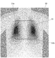
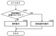
- FIG. 3 is a diagram illustrating an example of a print image output by the MFP illustrated in FIG. 2. It is a figure which shows an example of the print image as a comparative example with the print image shown in FIG. 10 is a flowchart of the operation of the print instruction apparatus according to the second embodiment of the present invention when instructing the MFP to print based on an input image. It is a figure which shows an example of the area
- FIG. 17 is a flowchart of an area selection operation shown in FIG. 16. FIG.
- FIG. 16 is a gradation histogram in the image of the region shown in FIG. 15.
- FIG. 19 is a gradation histogram shown in FIG. 18 after the expansion of the gradation width.
- FIG. 10 is a diagram illustrating an example of a print image output by an MFP according to a second embodiment of the present invention.
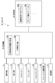
- FIG. 1 is a block diagram of an image forming system 10 according to the present embodiment.
- the image forming system 10 includes an MFP (Multifunction Peripheral) 20 as an image forming apparatus and a print instruction apparatus 30 that instructs the MFP 20 to perform printing.
- the MFP 20 and the print instruction apparatus 30 are communicably connected via a network 11 such as a LAN (Local Area Network) or the Internet, or directly connected by a cable such as a USB (Universal Serial Bus) cable or wireless communication. ing.
- a network 11 such as a LAN (Local Area Network) or the Internet
- a cable such as a USB (Universal Serial Bus) cable or wireless communication.
- FIG. 2 is a block diagram of the MFP 20.
- the MFP 20 includes an operation unit 21 that is an input device such as buttons for inputting various operations, and a display unit 22 that is a display device such as an LCD (Liquid Crystal Display) that displays various information.
- a scanner 23 that is a reading device that reads data from a document
- a printer 24 that is a printing device that executes printing on a recording medium such as paper, and a photo for detecting the color density of an image printed by the printer 24
- a sensor 25 a fax communication unit 26, which is a fax device that performs fax communication with an external facsimile apparatus (not shown) via a communication line such as a public telephone line, and the print instruction apparatus 30 via the network 11 (see FIG. 1).
- Communication devices that communicate with external devices A communication unit 27 is a scan, a semiconductor memory that stores various data, an HDD (Hard Disk Drive) storage unit 28 is a storage device such as, and a control unit 29 which controls the entire MFP 20.
- HDD Hard Disk Drive
- the MFP 20 replaces the device for connecting directly to the print instruction apparatus 30 with a cable such as a USB cable, or the device for connecting directly to the print instruction apparatus 30 with wireless communication, in place of the communication unit 27 or In addition to the communication unit 27, the communication unit 27 may be provided.
- the printer 24 is an electrophotographic printing device. There are four types of process colors of the printer 24: cyan, magenta, yellow, and black.
- the storage unit 28 stores an image processing program 28a for generating print image information for a print image based on the input image.
- the image processing program 28 a may be installed in the MFP 20 at the manufacturing stage of the MFP 20, may be additionally installed in the MFP 20 from a storage medium such as an SD card or a USB memory, or may be added to the MFP 20 from the network 11. May be installed.
- the storage unit 28 stores a gamma correction table 28b for correcting the halftone output characteristics of the printer 24 for each type of process color.
- the control unit 29 includes, for example, a CPU (Central Processing Unit), a ROM (Read Only Memory) storing programs and various data, and a RAM (Random Access Memory) used as a work area of the CPU. Computer.
- the CPU executes a program stored in the ROM or the storage unit 28.
- the control unit 29 executes the image processing program 28a stored in the storage unit 28, thereby generating print image information generation unit 29a that generates print image information for the print image based on the input image, and the print image It functions as a print execution unit 29b that outputs a print image according to the print image information generated by the information generation unit 29a.
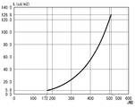
- FIG. 3 is a diagram showing the relationship between the luminance L reproducible on the recording medium by the MFP 20 and the discrimination threshold JND (Just Notifiable Difference).
- FIG. 4 is a diagram illustrating the relationship between the luminance L based on GSDF (Grayscale Standard Display Function) defined by DICOM (Digital Imaging and Communication in Medicine) and the discrimination threshold JDN. 3 is a diagram in which a part of the diagram shown in FIG. 4 is extracted.
- GSDF Gramyscale Standard Display Function
- DICOM Digital Imaging and Communication in Medicine
- Medical monitors typically have a typical image with a luminance in the range of about 100 cd / m2 to about 200 cd / m2, a mammographic image with a luminance in the range of about 200 cd / m2 to about 800 cd / m2, and an X-ray image about.
- the brightness is displayed in the range of 300 cd / m 2 to about 400 cd / m 2.
- the luminance that can be reproduced on the recording medium by the MFP 20 is in the range of 5.8 cd / m 2 to 126.8 cd / m 2. That is, the luminance range that can be reproduced on the recording medium by the MFP 20 is much narrower than the luminance range that can be reproduced by the medical monitor.
- FIG. 5 is a block diagram of the print instruction apparatus 30.
- the print instruction apparatus 30 includes an operation unit 31 that is an input device such as a mouse and a keyboard for inputting various operations, and a display unit 32 that is a display device such as an LCD that displays various information.
- a communication unit 33 that is a communication device that communicates with an external device such as the MFP 20 (see FIG. 1) via the network 11 (see FIG. 1), an HDD that stores programs and various data, and the like.
- a storage unit 34 that is a storage device and a control unit 35 that controls the entire print instruction apparatus 30 are provided.
- the print instruction apparatus 30 is configured by a computer such as a PC (Personal Computer).
- the print instruction apparatus 30 replaces the communication unit 33 with a device for connecting directly to the MFP 20 via a cable such as a USB cable, or a device for connecting directly to the MFP 20 via wireless communication, or a communication unit.
- a cable such as a USB cable
- a device for connecting directly to the MFP 20 via wireless communication or a communication unit.
- the control unit 35 includes, for example, a CPU, a ROM that stores programs and various data in advance, and a RAM that is used as a work area of the CPU.
- the CPU executes a program stored in the ROM or the storage unit 34.
- the MFP 20 may change the amount of toner adhering to the recording medium due to changes in temperature, humidity, etc., and the output characteristics may not be desired. Further, when the MFP 20 performs printing continuously for a long time, the output characteristics may not be desired due to the temperature of each part of the printer 24 changing. Further, as a result of the MFP 20 being used for a long period of time, output characteristics may not be desired due to changes in characteristics of each part of the printer 24, such as charging characteristics of the photosensitive drum.
- the MFP 20 executes calibration as shown in FIG. 6 when a certain environmental change condition such as humidity, temperature, or number of printed sheets is satisfied.
- FIG. 6 is a flowchart of the operation of the MFP 20 when executing calibration.
- control unit 29 of the MFP 20 draws an arbitrary screen pattern on the recording medium by the printer 24 for each type of process color (S101).
- control unit 29 reads the screen pattern drawn on the recording medium in S101 by the photosensor 25 and detects the density (S102).
- control unit 29 identifies the highest density that can be output by the printer 24 for each type of process color based on the density detected in S102 (S103).
- control unit 29 recognizes the original data of the screen pattern, the control unit 29 can determine, based on the original data, the region having the highest density among the screen patterns drawn on the recording medium in S101. .
- control unit 29 generates a gamma correction table for each type of process color based on the density detected in S102 (S104). That is, the control unit 29 generates a gamma correction table in which the output characteristics of the printer 24 become the same as the desired output characteristics, or the output characteristics of the printer 24 approach the desired output characteristics.
- control unit 29 updates the existing gamma correction table 28b with the gamma correction table generated in S104 (S105).
- control unit 29 specifies the luminance gradation width that can be reproduced by the printer 24 after the update of the gamma correction table 28b in S105 (S106), and ends the operation shown in FIG.
- the print instruction device 30 instructs the MFP 20 to print based on the monochrome input image. Then, when the input image output by the print instruction apparatus 30 is input, the MFP 20 executes the operation illustrated in FIG.
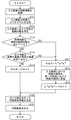
- FIG. 7 is a flowchart of the operation of the MFP 20 when outputting a print image based on the input image.
- the print image information generation unit 29a of the MFP 20 acquires the luminance information of the input image (S111), and generates a luminance histogram of the input image based on the luminance information acquired in S111 (S112). ).
- the print image information generation unit 29a specifies the difference between the highest luminance and the lowest luminance in the histogram generated in S112, that is, the luminance gradation width in the input image (S113).
- the print image information generation unit 29a determines whether or not the width specified in S113 exceeds the width specified in S106, that is, the luminance gradation width reproducible by the printer 24 (S114). .
- the print image information generation unit 29a determines in S114 that the luminance gradation width that can be reproduced by the printer 24 is not exceeded, the density specified in S103, that is, the highest density that can be output by the printer 24 is determined. It is determined whether the concentration is less than a specific concentration (S115).
- the specific density may be a fixed density or a density that can be changed via the operation unit 21 or the communication unit 27.
- the print image information generation unit 29a may set all types of process colors to be determined in S115, or may select only one type of process colors to be determined in S115. For example, since the medical image is normally monochrome, the print image information generation unit 29a may set only black among the process colors as a determination target in S115.
- the print image information generation unit 29a sets a plurality of types of process colors as the determination target in S115, the density specified in S103 for at least one of the target types is less than the specific density. When it is determined that there is, it may be determined in S115 that the density specified in S103 is less than the specific density, or the density specified in S103 for all the target types is less than the specific density. When it is determined that there is, it may be determined in S115 that the density specified in S103 is less than the specific density.
- the print image information generation unit 29a determines in S115 that the highest density that can be output by the printer 24 is not less than the specific density, the RGB value of the input image is converted into a CMYK value using a color conversion table (not shown). Conversion is performed (S116).
- the print image information generation unit 29a determines in S114 that the luminance gradation width that can be reproduced by the printer 24 is exceeded, or if the maximum density that can be output by the printer 24 is less than a specific density in S115. Judging, after converting the RGB values of the input image to the L * a * b * value (S117), L * a * b * gradation of brightness in the input image converted to a value of brightness in a single hue floors The key is converted into a key (S118).
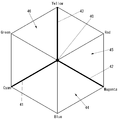
- FIG. 8 is a diagram showing a hue circle in the L * a * b * color space.
- FIG. 9 is a diagram showing the cyan equi-hue surface 41 when the luminance gradation in the input image is converted into the lightness gradation in the cyan hue.
- the print image information generation unit 29a changes the brightness gradation in the input image to the brightness gradation on the cyan equi-hue surface 41 (see FIG. 8) as shown in FIG. Can be converted to
- the print image information generation unit 29a has a saturation of zero, that is, the color existing on the line segment 40 on the L * axis, while maintaining the lightness, the outermost shell 41a of the cyan equal hue surface 41.
- the upper color that is, the pure color 41b or the clear color can be converted.
- FIG. 10 is a diagram showing the pure color 41b and the clear color on the cyan equi-hue surface 41.
- FIG. FIG. 11 is a diagram showing the relationship between the luminance L that can be reproduced on the recording medium by the MFP 20 and the pure color 41b and the clear color on the cyan equal hue plane 41.
- the pure color 41b having the highest saturation and the clear color 41c having a lightness higher than the pure color 41b among the clear colors on the cyan equal hue plane 41 are reproduced only by cyan among the process colors. Is possible.
- the dark clear color 41d having lightness lower than that of the pure color 41b among the clear colors can be reproduced only with cyan and black among the process colors. That is, in S118 shown in FIG. 7, the print image information generation unit 29a converts the luminance gradation in the input image into a cyan hue expressed by two kinds of process colors, cyan and black, as shown in FIG. It can be converted to lightness gradation.
- the print image information generation unit 29a displays the magenta equal hue plane 42 (see FIG. 8) in which the luminance gradation in the input image is expressed by two types of process colors, magenta and black. ) In the lightness gradation. Further, in S118, the print image information generation unit 29a displays the brightness gradation of the input image in the same hue plane 43 (see FIG. 8) of yellow, which is expressed by two kinds of process colors, yellow and black. It can be converted into gradation.
- the print image information generation unit 29a includes a region 44 including a blue equi-hue surface with the luminance gradation in the input image sandwiched between the equi-hue surface 41 and the equi-hue surface 42 (FIG. 8). In the same hue plane represented by three kinds of process colors of cyan, magenta, and black.
- the print image information generation unit 29a includes a region 45 (see FIG. 8) in which the luminance gradation in the input image is sandwiched between the equal hue plane 42 and the equal hue plane 43 and includes the red hue hue. In the same hue plane in the same hue plane expressed by three process colors of magenta, yellow and black.
- the print image information generation unit 29a includes a region 46 including a green (GREEn) hue plane sandwiched between the equal hue plane 41 and the equal hue plane 43 (see FIG. 8).
- GREEn green
- the print image information generation unit 29a converts the luminance gradation in the input image into the lightness gradation in which hue, or via the operation unit 21, the communication unit 27, or the like. It may be changeable.
- the print image information generation unit 29a converts the L * a * b * value generated in S118 into a CMYK value (S119).
- the print image information generation unit 29a After the processing of S116, the print image information generation unit 29a performs gamma correction by the gamma correction table 28b on the image information converted into CMYK values in S116, and generates print image information (S120). Therefore, monochrome print image information is generated.
- the print image information generation unit 29a After the process of S119, the print image information generation unit 29a performs gamma correction by the gamma correction table 28b on the image information converted into CMYK values in S119, and generates print image information (S120). Therefore, the color print image information of a single hue is generated.
- the print execution unit 29b of the MFP 20 outputs a print image by the printer 24 according to the print image information generated in S120 (S121), and ends the operation shown in FIG.
- FIG. 12 is a diagram illustrating an example of a print image output by the MFP 20.
- FIG. 13 is a diagram illustrating an example of a print image as a comparative example with the print image illustrated in FIG. 12.
- the MFP 20 exceeds the luminance gradation range that can be reproduced by the printer 24 (YES in S114), or the highest density that can be output by the printer 24 is less than a specific density (YES in S115). )
- the print image information is generated by the processing of S116 without converting the luminance gradation in the input image into the lightness gradation in a single hue, the gradation in the input image is appropriately determined depending on the print image. Therefore, as shown in FIG. 13, it is impossible to reproduce the same gradation as the input image.
- the MFP 20 exceeds the gradation range of brightness that can be reproduced by the printer 24 (YES in S114), or the maximum density that can be output by the printer 24 is less than a specific density (YES in S115). ),
- the brightness gradation in the input image is converted into the brightness gradation in a single hue (S118), and print image information is generated (S120). Therefore, as shown in FIG. The gradation can be reproduced.
- the MFP 20 converts the luminance gradation in the input image into the lightness gradation in a single hue (S118) and generates print image information (S120).
- the print image is output (S121)
- the MFP 20 can reduce the types of process colors to be used.
- the MFP 20 can reduce the types of process colors to be used, the toner consumption can be suppressed. Therefore, the MFP 20 can reduce the cost.
- the MFP 20 can reduce the types of process colors to be used, even if the toner of any process color has run out, it can be input by using the process color that has not run out of toner.
- the brightness gradation in the image can be reproduced as the brightness gradation in a single hue in the printed image.
- the MFP 20 sets the luminance gradation in the input image to the brightness in a single hue. Since it is reproduced as a gradation (S118), the gradation in the input image can be appropriately reproduced by the print image.
- the MFP 20 may execute the process of S115 after the process of S113 without providing the process of S114. Further, the MFP 20 may be configured to execute the process of S116 in the case of NO in S114 without providing the process of S115. Further, the MFP 20 may execute the process of S117 after the process of S113 without providing either the process of S114 or the process of S115.
- the MFP 20 performs the specification of the highest density that can be output by the printer 24 and the specification of the luminance gradation width that can be reproduced by the printer 24 in the calibration operation shown in FIG. 6 may be executed in an operation different from the calibration operation shown in FIG.
- the configuration of the image forming system according to the present embodiment is the same as the configuration of the image forming system 10 (see FIG. 1) according to the first embodiment. Therefore, in the configuration of the image forming system according to the present embodiment, the same configuration as the configuration of the image forming system 10 is denoted by the same reference numeral as the configuration of the image forming system 10 and detailed description thereof is omitted.
- the print instruction apparatus 30 starts the operation illustrated in FIG.
- FIG. 14 is a flowchart of the operation of the print instruction apparatus 30 when instructing the MFP 20 to print based on the input image.
- control unit 35 of the print instruction apparatus 30 determines whether or not an instruction to execute a print instruction based on the input image is instructed via the operation unit 31 (S131).
- control unit 35 determines in S131 that execution of a print instruction based on the input image is not instructed, it determines whether or not selection of a region in the input image is instructed via the operation unit 31 (S132). .
- the control unit 35 designates an arbitrary start point 51 a and end point 51 b with respect to the input image 50 displayed on the display unit 32, thereby causing the input image 50 to have a rectangular shape. The selection of the area 51 is instructed.
- control unit 35 determines in S132 that selection of the region 51 in the input image is instructed via the operation unit 31, the control unit 35 generates region information including the coordinates of the start point 51a and the end point 51b in the input image of the instructed region 51. (S133).
- the control unit 35 determines in S132 that selection of the region 51 in the input image is not instructed via the operation unit 31, or executes the processing in S131 when the processing in S133 is completed.
- control unit 35 determines in S131 that execution of a print instruction based on the input image has been instructed, the control unit 35 determines whether or not the area information generated in S133 exists (S134).
- control unit 35 When determining in S134 that the area information exists, the control unit 35 transmits the input image and the area information generated in S133 to the MFP 20 (S135), and ends the operation illustrated in FIG.
- control unit 35 determines in S134 that there is no area information, the control unit 35 transmits the input image to the MFP 20 (S136), and ends the operation shown in FIG.
- the MFP 20 executes the operation illustrated in FIG.
- FIG. 16 is a flowchart of the operation of the MFP 20 when a print image is output based on the input image.
- control unit 29 of the MFP 20 determines whether or not region information has been transmitted together with the input image (S141).
- control unit 29 determines in S141 that the area information has not been transmitted together with the input image, the control unit 29 performs the same normal operation as the operation illustrated in FIG. 7 (S142), and ends the operation illustrated in FIG.
- control unit 29 determines in S141 that the region information has been transmitted together with the input image, the control unit 29 executes the region selection operation shown in FIG. 17 (S143), and ends the operation shown in FIG.
- the print image information generation unit 29a of the control unit 29 executes S151 to S159 similar to S111 to S119 (see FIG. 7).
- the print image information generation unit 29a extends the gradation width in the image of the area 51 indicated by the area information transmitted together with the input image to a reproducible gradation width ( S160).
- a gradation histogram in the image of the region 51 is shown in FIG. 18, and a gradation histogram after expansion of the gradation width is shown in FIG.
- the gradation min is the minimum value of the gradation before expansion in the image of the region 51.
- the gradation max is the maximum value of the gradation before expansion in the image in the region 51.
- the gradation min ′ is the minimum reproducible gradation and is zero.
- the gradation max ′ is the maximum reproducible gradation value, and is 2 N ⁇ 1 when the reproducible gradation is N bits.
- An arbitrary gradation before expansion in the image of the region 51 is expanded as shown in the following expression using the gradation max and gradation min.
- Gradation after expansion (2 N ⁇ 1) ⁇ (gradation before expansion ⁇ min) / (max ⁇ min)
- the print image information generation unit 29a inverts the gradation in the image other than the area 51 after the process of S160 (S161).
- the print image information generation unit 29a executes S162 and S163 similar to S120 and S121 (see FIG. 7), and ends the operation shown in FIG.
- FIG. 20 is a diagram illustrating an example of a print image output by the MFP 20.
- the MFP 20 expands the gradation width in the image of the area 51 to a reproducible gradation width (S160) and inverts the gradation in the image other than the area 51 (S161). Therefore, as shown in FIG. 20, regarding the image in the region 51, it is possible to reproduce the same gradation as that of the input image.
- the MFP 20 when generating print image information based on an input image, the MFP 20 can reproduce the brightness gradation width in the image of the region 51 in a single hue in a single hue. Since it is expanded to the brightness gradation width (S160), even in the case where the gradation in the entire input image cannot be properly reproduced by the print image, in the image of the selected region 51 in the input image. The gradation can be appropriately reproduced by the printed image.
- the MFP 20 expands the brightness gradation width in the image of the area 51 in a single hue to a brightness gradation width that can be reproduced in a single hue, the MFP 20 images other than the area 51 in the input image. Therefore, the gradation in the image of the selected region 51 in the input image can be made conspicuous in the print image.
- both the print image information generation unit and the print execution unit are realized by the image forming apparatus in each of the above-described embodiments, but at least one of the print image information generation unit and the print execution unit.
- the unit may be realized by a print instruction apparatus.
- the print instruction apparatus may function as the print image information generation unit by executing an image processing program for realizing the print image information generation unit by the print instruction apparatus.
- the print image information generation unit may cause the input image to have a luminance gradation width that exceeds a luminance gradation width that can be reproduced by the print execution unit.
- Print image information may be generated by converting the luminance gradation into a lightness gradation in a single hue.
- the image forming apparatus of the present invention can change the luminance gradation in the input image to a single in the printed image. Since it is reproduced as a lightness gradation in the hue, the gradation in the input image can be appropriately reproduced by the print image.
- the print image information generation unit sets the luminance gradation in the input image in a single hue when the maximum density that can be output by the print execution unit is less than a specific density.
- Print image information may be generated by converting to lightness gradation.
- the image forming apparatus reduces the luminance gradation in the input image in the printed image when the performance of reproducing the luminance gradation in the input image as the luminance gradation in the printed image is degraded. Since reproduction is performed as lightness gradation in a single hue, gradation in an input image can be appropriately reproduced by a print image.
- the print image information generation unit converts the luminance gradation in the image of the specific area selected from the input image into the lightness gradation in a single hue.
- the brightness gradation width in an image of a specific region in a single hue may be expanded to the brightness gradation width in a single hue that can be reproduced by the print execution unit.
- the image forming apparatus of the present invention when the image forming apparatus of the present invention generates print image information based on an input image, the brightness gradation width in an image of a specific region in a single hue is set in a single hue. Since it is expanded to the gradation range of lightness that can be reproduced, even if the gradation in the entire input image cannot be properly reproduced by the print image, the image of the specific area selected in the input image Can be appropriately reproduced by the printed image.
- the print image information generation unit has a brightness gradation in a single hue that can be reproduced by the print execution unit in a brightness gradation width in an image of a specific region in a single hue.
- the gradation in the image other than the specific area in the input image may be inverted.
- the image forming apparatus of the present invention can expand the lightness gradation width in an image of a specific region in a single hue to a lightness gradation width that can be reproduced in a single hue. Since the gradation in the image other than the specific area in the input image is inverted, the gradation in the image in the specific area selected from the input image can be made conspicuous in the print image.
- the image forming apparatus of the present invention is an MFP in each of the above-described embodiments, but may be an image forming apparatus other than the MFP, such as a dedicated printer.
Landscapes
- Engineering & Computer Science (AREA)
- Multimedia (AREA)
- Signal Processing (AREA)
- Theoretical Computer Science (AREA)
- Human Computer Interaction (AREA)
- Physics & Mathematics (AREA)
- General Engineering & Computer Science (AREA)
- General Physics & Mathematics (AREA)
- Facsimile Image Signal Circuits (AREA)
- Color, Gradation (AREA)
- Color Image Communication Systems (AREA)
- Image Processing (AREA)
Abstract
使用するプロセスカラーの種類を低減することができる画像形成装置および画像形成システムを提供する。 MFP(20)は、入力画像に基づいて印刷画像のための印刷画像情報を生成する印刷画像情報生成部(29a)と、印刷画像情報生成部(29a)によって生成された印刷画像情報に応じて印刷画像を出力する(S121)印刷実行部(29b)とを備え、印刷画像情報生成部(29a)は、入力画像における輝度の階調を、2種類以上のプロセスカラーで表現される単一の色相における明度の階調に変換して(S118)印刷画像情報を生成する(S120)ことを特徴とする。
Description
本発明は、入力画像における輝度の階調を印刷画像において再現する画像形成装置および画像形成システムに関する。
医療の分野では、CT(Computed Tomography)、MRI(Magnetic Resonance Imaging)、CR(Computed Radiography)、FPD(Flat Panel Detector)、超音波診断装置などの各種の医用画像生成装置によってデジタル画像として生成された医用画像を、CRT(Cathode Ray Tube)などの画像表示装置による表示によって出力したり、プリンターなどの画像形成装置によって印刷画像として出力したりする医用画像システムが利用されている。
近年、病院内のネットワークや、病院間のネットワークの進展に伴い、医用画像システムは、複数のメーカーの様々な機種で構成されることが増えている。このため、同一の医用画像であっても、出力する画像表示装置や画像形成装置の機種によって、出力された画像の階調が異なって再現されるという問題が生じる。このような中で、画像表示装置や画像形成装置の階調特性に依存せずに医用画像の見え方を整合させる要求が高まっている。
そのような要求に対応する方法として、従来、入力画像における輝度の階調を印刷画像における輝度の階調によって表現することができない場合に、入力画像における輝度の階調を印刷画像における色相の階調によって表現する方法が知られている(例えば、特許文献1参照。)。
しかしながら、従来の方法においては、プロセスカラーの全てが使用される必要があるという問題がある。
そこで、本発明は、使用するプロセスカラーの種類を低減することができる画像形成装置および画像形成システムを提供することを目的とする。
本発明の画像形成装置は、入力画像に基づいて印刷画像のための印刷画像情報を生成する印刷画像情報生成部と、前記印刷画像情報生成部によって生成された前記印刷画像情報に応じて前記印刷画像を出力する印刷実行部とを備え、前記印刷画像情報生成部は、前記入力画像における輝度の階調を、2種類以上のプロセスカラーで表現される単一の色相における明度の階調に変換して前記印刷画像情報を生成することを特徴とする。
この構成により、本発明の画像形成装置は、入力画像における輝度の階調を単一の色相における明度の階調に変換して印刷画像情報を生成するので、印刷画像情報に応じて印刷画像が出力される場合にプロセスカラーの全てが使用されることを防止することができる。したがって、本発明の画像形成装置は、使用するプロセスカラーの種類を低減することができる。
本発明の画像形成システムは、入力画像に基づいて印刷画像のための印刷画像情報を生成する印刷画像情報生成部と、前記印刷画像情報生成部によって生成された前記印刷画像情報に応じて前記印刷画像を出力する印刷実行部とを備え、前記印刷画像情報生成部は、前記入力画像における輝度の階調を、2種類以上のプロセスカラーで表現される単一の色相における明度の階調に変換して前記印刷画像情報を生成することを特徴とする。
この構成により、本発明の画像形成システムは、入力画像における輝度の階調を単一の色相における明度の階調に変換して印刷画像情報を生成するので、印刷画像情報に応じて印刷画像が出力される場合にプロセスカラーの全てが使用されることを防止することができる。したがって、本発明の画像形成システムは、使用するプロセスカラーの種類を低減することができる。
本発明の画像形成装置および画像形成システムは、使用するプロセスカラーの種類を低減することができる。
以下、本発明の実施の形態について、図面を用いて説明する。
(第1の実施の形態)
まず、第1の実施の形態に係る画像形成システムの構成について説明する。
まず、第1の実施の形態に係る画像形成システムの構成について説明する。
図1は、本実施の形態に係る画像形成システム10のブロック図である。
図1に示すように、画像形成システム10は、画像形成装置としてのMFP(Multifunction Peripheral)20と、MFP20に印刷を指示する印刷指示装置30とを備えている。MFP20と、印刷指示装置30とは、LAN(Local Area Network)、インターネットなどのネットワーク11を介して通信可能に接続されているか、USB(Universal Serial Bus)ケーブルなどのケーブルや無線通信によって直接接続されている。
図2は、MFP20のブロック図である。
図2に示すように、MFP20は、種々の操作が入力されるボタンなどの入力デバイスである操作部21と、種々の情報を表示するLCD(Liquid Crystal Display)などの表示デバイスである表示部22と、原稿からデータを読み取る読取デバイスであるスキャナー23と、用紙などの記録媒体に印刷を実行する印刷デバイスであるプリンター24と、プリンター24によって印刷された画像の色の濃度を検出するためのフォトセンサー25と、図示していない外部のファクシミリ装置と公衆電話回線などの通信回線経由でファックス通信を行うファックスデバイスであるファックス通信部26と、ネットワーク11(図1参照。)経由で印刷指示装置30(図1参照。)など、外部の装置と通信を行う通信デバイスである通信部27と、各種のデータを記憶している半導体メモリー、HDD(Hard Disk Drive)などの記憶デバイスである記憶部28と、MFP20全体を制御する制御部29とを備えている。
なお、MFP20は、USBケーブルなどのケーブルによって印刷指示装置30と直接接続されるためのデバイスや、無線通信によって印刷指示装置30と直接接続されるためのデバイスを、通信部27に代えて、または、通信部27に加えて、備えていても良い。
プリンター24は、電子写真方式の印刷デバイスである。プリンター24のプロセスカラーは、シアン(Cyan)、マゼンタ(Magenta)、イエロー(Yellow)、および、ブラック(Black)の4種類である。
記憶部28は、入力画像に基づいて印刷画像のための印刷画像情報を生成するための画像処理プログラム28aを記憶している。画像処理プログラム28aは、MFP20の製造段階でMFP20にインストールされていても良いし、SDカード、USBメモリーなどの記憶媒体からMFP20に追加でインストールされても良いし、ネットワーク11上からMFP20に追加でインストールされても良い。
記憶部28は、プリンター24による中間調の出力特性を補正するためのガンマ補正テーブル28bをプロセスカラーの種類毎に記憶している。
制御部29は、例えば、CPU(Central Processing Unit)と、プログラムおよび各種のデータを記憶しているROM(Read Only Memory)と、CPUの作業領域として用いられるRAM(Random Access Memory)とを備えているコンピューターである。CPUは、ROMまたは記憶部28に記憶されているプログラムを実行する。
制御部29は、記憶部28に記憶されている画像処理プログラム28aを実行することによって、入力画像に基づいて印刷画像のための印刷画像情報を生成する印刷画像情報生成部29a、および、印刷画像情報生成部29aによって生成された印刷画像情報に応じて印刷画像を出力する印刷実行部29bとして機能する。
図3は、MFP20によって記録媒体上に再現可能な輝度Lと、弁別閾JND(Just Noticeable Difference)との関係を示す図である。図4は、DICOM(Digital Imaging and COmmunication in Medicine)で定義されているGSDF(Grayscale Standard Display Function)に基づいた輝度Lと、弁別閾JDNとの関係を示す図である。図3に示す図は、図4に示す図の一部を抜き出した図である。
医用のモニターは、通常、一般の画像を約100cd/m2~約200cd/m2の範囲の輝度で、マンモグラフィーの画像を約200cd/m2~約800cd/m2の範囲の輝度で、レントゲンの画像を約300cd/m2~約400cd/m2の範囲の輝度で表示している。しかしながら、図3に示すように、MFP20によって記録媒体上に再現可能な輝度は、5.8cd/m2~126.8cd/m2の範囲である。すなわち、MFP20によって記録媒体上に再現可能な輝度の範囲は、医用のモニターによって再現可能な輝度の範囲より遥かに狭い。
図5は、印刷指示装置30のブロック図である。
図5に示すように、印刷指示装置30は、種々の操作が入力されるマウスやキーボードなどの入力デバイスである操作部31と、種々の情報を表示するLCDなどの表示デバイスである表示部32と、ネットワーク11(図1参照。)経由でMFP20(図1参照。)など、外部の装置と通信を行う通信デバイスである通信部33と、プログラムおよび各種のデータを記憶しているHDDなどの記憶デバイスである記憶部34と、印刷指示装置30全体を制御する制御部35とを備えている。印刷指示装置30は、PC(Personal Computer)などのコンピューターによって構成されている。
なお、印刷指示装置30は、USBケーブルなどのケーブルによってMFP20と直接接続されるためのデバイスや、無線通信によってMFP20と直接接続されるためのデバイスを、通信部33に代えて、または、通信部33に加えて、備えていても良い。
制御部35は、例えば、CPUと、プログラムおよび各種のデータを予め記憶しているROMと、CPUの作業領域として用いられるRAMとを備えている。CPUは、ROMまたは記憶部34に記憶されているプログラムを実行するようになっている。
次に、画像形成システム10の動作について説明する。
まず、出力特性を所望のものにするためのキャリブレーションを実行する場合のMFP20の動作について説明する。
MFP20は、温度や湿度などが変化することによって、記録媒体に付着するトナーの量が変化して、出力特性が所望のものでなくなることがある。また、MFP20は、長時間、連続的に印刷を実行するような場合に、プリンター24の各部の温度などが変化することによって、出力特性が所望のものでなくなることもある。また、MFP20は、長期間、使用された結果、プリンター24の各部の特性、例えば感光ドラムの帯電特性などが変化することによって、出力特性が所望のものでなくなることもある。
したがって、MFP20は、湿度、温度または印刷枚数などの一定の環境変化の条件を満たした場合に、図6に示すように、キャリブレーションを実行する。
図6は、キャリブレーションを実行する場合のMFP20の動作のフローチャートである。
図6に示すように、MFP20の制御部29は、プロセスカラーの種類毎にプリンター24によって任意のスクリーン・パターンを記録媒体上に描画する(S101)。
次いで、制御部29は、S101において記録媒体上に描画したスクリーン・パターンをフォトセンサー25によって読み取って濃度を検出する(S102)。
次いで、制御部29は、S102によって検出した濃度に基づいて、プリンター24によって出力可能な最高の濃度をプロセスカラーの種類毎に特定する(S103)。ここで、制御部29は、スクリーン・パターンの元データを認識しているので、S101において記録媒体上に描画したスクリーン・パターンのうち濃度が最高の領域を元データに基づいて判断することができる。
次いで、制御部29は、S102によって検出した濃度に基づいて、プロセスカラーの種類毎にガンマ補正テーブルを生成する(S104)。すなわち、制御部29は、プリンター24の出力特性が所望の出力特性と同一になる、または、プリンター24の出力特性が所望の出力特性に近づくようなガンマ補正テーブルを生成する。
次いで、制御部29は、S104において生成したガンマ補正テーブルによって既存のガンマ補正テーブル28bを更新する(S105)。
次いで、制御部29は、S105におけるガンマ補正テーブル28bの更新後のプリンター24によって再現可能な輝度の階調の幅を特定して(S106)、図6に示す動作を終了する。
次に、入力画像に基づいて印刷画像を出力する場合のMFP20の動作について説明する。
印刷指示装置30は、モノクロの入力画像に基づいた印刷をMFP20に指示する。そして、MFP20は、印刷指示装置30によって出力された入力画像が入力されると、図7に示す動作を実行する。
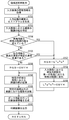
図7は、入力画像に基づいて印刷画像を出力する場合のMFP20の動作のフローチャートである。
図7に示すように、MFP20の印刷画像情報生成部29aは、入力画像の輝度情報を取得して(S111)、S111によって取得した輝度情報に基づいて入力画像の輝度のヒストグラムを生成する(S112)。
次いで、印刷画像情報生成部29aは、S112において生成したヒストグラムにおける最高の輝度と、最低の輝度との差、すなわち、入力画像における輝度の階調の幅を特定する(S113)。
次いで、印刷画像情報生成部29aは、S113において特定した幅がS106において特定されている幅、すなわち、プリンター24によって再現可能な輝度の階調の幅を超えているか否かを判断する(S114)。
印刷画像情報生成部29aは、プリンター24によって再現可能な輝度の階調の幅を超えていないとS114において判断すると、S103において特定されている濃度、すなわち、プリンター24によって出力可能な最高の濃度が特定の濃度未満であるか否かを判断する(S115)。ここで、特定の濃度は、固定の濃度であっても良いし、操作部21や通信部27などを介して変更可能な濃度であっても良い。
なお、印刷画像情報生成部29aは、プロセスカラーの全ての種類をS115の判断の対象にしても良いし、プロセスカラーの何れかの種類のみをS115の判断の対象にしても良い。例えば、医用の画像が通常モノクロであるので、印刷画像情報生成部29aは、プロセスカラーのうちブラックのみをS115の判断の対象にしても良い。また、印刷画像情報生成部29aは、プロセスカラーの複数の種類をS115の判断の対象にする場合、対象の種類のうち何れか少なくとも1種類についてS103において特定されている濃度が特定の濃度未満であると判断したときに、S103において特定されている濃度が特定の濃度未満であるとS115において判断しても良いし、対象の種類の全てについてS103において特定されている濃度が特定の濃度未満であると判断したときに、S103において特定されている濃度が特定の濃度未満であるとS115において判断しても良い。
印刷画像情報生成部29aは、プリンター24によって出力可能な最高の濃度が特定の濃度未満ではないとS115において判断すると、図示していない色変換テーブルを使用して入力画像のRGB値をCMYK値に変換する(S116)。
印刷画像情報生成部29aは、プリンター24によって再現可能な輝度の階調の幅を超えているとS114において判断するか、プリンター24によって出力可能な最高の濃度が特定の濃度未満であるとS115において判断すると、入力画像のRGB値をL*a*b*値に変換した後(S117)、L*a*b*値に変換した入力画像における輝度の階調を単一の色相における明度の階調に変換する(S118)。
図8は、L*a*b*色空間における色相環を示す図である。図9は、入力画像における輝度の階調がシアンの色相における明度の階調に変換された場合のシアンの等色相面41を示す図である。
例えば、印刷画像情報生成部29aは、図7に示すS118において、入力画像における輝度の階調を、図9に示すように、シアンの等色相面41(図8参照。)における明度の階調に変換することができる。すなわち、印刷画像情報生成部29aは、彩度がゼロ、すなわち、L*軸上の線分40上に存在している色を、明度を維持したままシアンの等色相面41の最外殻41a上の色、すなわち、純色41bまたは清色に変換することができる。
図10は、シアンの等色相面41における純色41bおよび清色を示す図である。図11は、MFP20によって記録媒体上に再現可能な輝度Lと、シアンの等色相面41における純色41bおよび清色との関係を示す図である。
図10に示すように、シアンの等色相面41において、彩度が最高である純色41bと、清色のうち純色41bより明度が高い明清色41cとは、プロセスカラーのうちシアンのみによって再現することが可能である。一方、清色のうち純色41bより明度が低い暗清色41dは、プロセスカラーのうちシアンおよびブラックのみによって再現することが可能である。すなわち、印刷画像情報生成部29aは、図7に示すS118において、入力画像における輝度の階調を、図11に示すように、シアンおよびブラックという2種類のプロセスカラーで表現されるシアンの色相における明度の階調に変換することができる。
以上においては、印刷画像情報生成部29aが入力画像における輝度の階調をシアンの色相における明度の階調に変換する場合について説明している。しかしながら、シアン以外の色相についても同様である。
例えば、印刷画像情報生成部29aは、図7に示すS118において、入力画像における輝度の階調を、マゼンタおよびブラックという2種類のプロセスカラーで表現されるマゼンタの等色相面42(図8参照。)における明度の階調に変換することができる。また、印刷画像情報生成部29aは、S118において、入力画像における輝度の階調を、イエローおよびブラックという2種類のプロセスカラーで表現されるイエローの等色相面43(図8参照。)における明度の階調に変換することができる。
また、印刷画像情報生成部29aは、S118において、入力画像における輝度の階調を、等色相面41および等色相面42に挟まれてブルー(Blue)の等色相面を含む領域44(図8参照。)内の等色相面、すなわち、シアン、マゼンタおよびブラックという3種類のプロセスカラーで表現される等色相面における明度の階調に変換することができる。また、印刷画像情報生成部29aは、S118において、入力画像における輝度の階調を、等色相面42および等色相面43に挟まれてレッド(Red)の等色相面を含む領域45(図8参照。)内の等色相面、すなわち、マゼンタ、イエローおよびブラックという3種類のプロセスカラーで表現される等色相面における明度の階調に変換することができる。また、印刷画像情報生成部29aは、S118において、入力画像における輝度の階調を、等色相面41および等色相面43に挟まれてグリーン(Green)の等色相面を含む領域46(図8参照。)内の等色相面、すなわち、シアン、イエローおよびブラックという3種類のプロセスカラーで表現される等色相面における明度の階調に変換することができる。
なお、印刷画像情報生成部29aが入力画像における輝度の階調を何れの色相における明度の階調に変換するかは、固定であっても良いし、操作部21や通信部27などを介して変更可能であっても良い。
図7に示すように、印刷画像情報生成部29aは、S118の処理が終了すると、S118において生成したL*a*b*値をCMYK値に変換する(S119)。
印刷画像情報生成部29aは、S116の処理の後、S116においてCMYK値に変換した画像情報に対してガンマ補正テーブル28bによるガンマ補正を行って印刷画像情報を生成する(S120)。したがって、モノクロの印刷画像情報が生成される。
印刷画像情報生成部29aは、S119の処理の後、S119においてCMYK値に変換した画像情報に対してガンマ補正テーブル28bによるガンマ補正を行って印刷画像情報を生成する(S120)。したがって、単一の色相のカラーの印刷画像情報が生成される。
MFP20の印刷実行部29bは、S120の処理が終了すると、S120において生成された印刷画像情報に応じてプリンター24によって印刷画像を出力して(S121)、図7に示す動作を終了する。
図12は、MFP20によって出力される印刷画像の一例を示す図である。図13は、図12に示す印刷画像との比較例としての印刷画像の一例を示す図である。
仮に、MFP20が、プリンター24によって再現可能な輝度の階調の幅を超えている場合(S114でYES)や、プリンター24によって出力可能な最高の濃度が特定の濃度未満である場合(S115でYES)に、入力画像における輝度の階調を単一の色相における明度の階調に変換せずにS116の処理によって印刷画像情報を生成する構成であるとき、入力画像における階調を印刷画像によって適切に再現することができないので、図13に示すように、入力画像と同等の階調を再現することはできない。しかしながら、MFP20は、プリンター24によって再現可能な輝度の階調の幅を超えている場合(S114でYES)や、プリンター24によって出力可能な最高の濃度が特定の濃度未満である場合(S115でYES)に、入力画像における輝度の階調を単一の色相における明度の階調に変換して(S118)印刷画像情報を生成する(S120)ので、図12に示すように、入力画像と同等の階調を再現することができる。
以上に説明したように、MFP20は、入力画像における輝度の階調を単一の色相における明度の階調に変換して(S118)印刷画像情報を生成する(S120)ので、印刷画像情報に応じて印刷画像が出力される(S121)場合にプロセスカラーの全てが使用されることを防止することができる。したがって、MFP20は、使用するプロセスカラーの種類を低減することができる。
MFP20は、使用するプロセスカラーの種類を低減することができるので、トナーの消費量を抑えることができる。したがって、MFP20は、コストを削減することができる。
また、MFP20は、使用するプロセスカラーの種類を低減することができるので、何れかのプロセスカラーのトナーが切れている場合であっても、トナーが切れていないプロセスカラーを使用することによって、入力画像における輝度の階調を印刷画像において単一の色相における明度の階調として再現することができる。
MFP20は、入力画像における輝度の階調を印刷画像において輝度の階調として再現することができない場合に(S114でYES)、入力画像における輝度の階調を印刷画像において単一の色相における明度の階調として再現する(S118)ので、入力画像における階調を印刷画像によって適切に再現することができる。
図3に示すように、人間は、輝度が低い領域、すなわち、印刷の濃度が高い領域では、階調の変化を感じ易く、輝度が高い領域、すなわち、印刷の濃度が低い領域では、階調の変化を感じ難い。すなわち、MFP20は、プリンター24によって出力可能な最高の濃度が特定の濃度未満である場合に(S115でYES)、入力画像における輝度の階調を印刷画像において輝度の階調として再現する性能が低下している。MFP20は、入力画像における輝度の階調を印刷画像において輝度の階調として再現する性能が低下している場合に(S115でYES)、入力画像における輝度の階調を印刷画像において単一の色相における明度の階調として再現する(S118)ので、入力画像における階調を印刷画像によって適切に再現することができる。
なお、MFP20は、S114の処理を設けずに、S113の処理の後、S115の処理を実行するようになっていても良い。また、MFP20は、S115の処理を設けずに、S114でNOの場合にS116の処理を実行するようになっていても良い。また、MFP20は、S114の処理と、S115の処理との何れも設けずに、S113の処理の後、S117の処理を実行するようになっていても良い。
また、MFP20は、プリンター24によって出力可能な最高の濃度の特定と、プリンター24によって再現可能な輝度の階調の幅の特定とを図6に示すキャリブレーションの動作において実行しているが、図6に示すキャリブレーションの動作とは別の動作において実行するようになっていても良い。
(第2の実施の形態)
まず、第2の実施の形態に係る画像形成システムの構成について説明する。
まず、第2の実施の形態に係る画像形成システムの構成について説明する。
本実施の形態に係る画像形成システムの構成は、第1の実施の形態に係る画像形成システム10(図1参照。)の構成と同様である。したがって、本実施の形態に係る画像形成システムの構成のうち、画像形成システム10の構成と同様の構成については、画像形成システム10の構成と同一の符号を付して詳細な説明を省略する。
次に、本実施の形態に係る画像形成システムの動作について説明する。
まず、モノクロの入力画像に基づいた印刷をMFP20に指示する場合の印刷指示装置30の動作について説明する。
印刷指示装置30は、入力画像に基づいた印刷の指示の開始が操作部31を介して指示されると、図14に示す動作を開始する。
図14は、入力画像に基づいた印刷をMFP20に指示する場合の印刷指示装置30の動作のフローチャートである。
図14に示すように、印刷指示装置30の制御部35は、入力画像に基づいた印刷の指示の実行が操作部31を介して指示されたか否かを判断する(S131)。
制御部35は、入力画像に基づいた印刷の指示の実行が指示されていないとS131において判断すると、入力画像において領域の選択が操作部31を介して指示されたか否かを判断する(S132)。ここで、制御部35は、例えば、図15に示すように、表示部32に表示している入力画像50に対して任意の始点51aおよび終点51bが指定されることによって、入力画像50において矩形の領域51の選択が指示される。
制御部35は、入力画像において領域51の選択が操作部31を介して指示されたとS132において判断すると、指示された領域51の入力画像における始点51aおよび終点51bの座標を含む領域情報を生成する(S133)。
制御部35は、入力画像において領域51の選択が操作部31を介して指示されていないとS132において判断するか、S133の処理が終了すると、S131の処理を実行する。
制御部35は、入力画像に基づいた印刷の指示の実行が指示されたとS131において判断すると、S133において生成された領域情報が存在するか否かを判断する(S134)。
制御部35は、領域情報が存在するとS134において判断すると、入力画像と、S133において生成された領域情報とをMFP20に送信して(S135)、図14に示す動作を終了する。
制御部35は、領域情報が存在しないとS134において判断すると、入力画像をMFP20に送信して(S136)、図14に示す動作を終了する。
次に、入力画像に基づいて印刷画像を出力する場合のMFP20の動作について説明する。
MFP20は、印刷指示装置30によって出力された入力画像が入力されると、図16に示す動作を実行する。
図16は、入力画像に基づいて印刷画像を出力する場合のMFP20の動作のフローチャートである。
図16に示すように、MFP20の制御部29は、入力画像とともに領域情報が送信されてきたか否かを判断する(S141)。
制御部29は、入力画像とともに領域情報が送信されてきていないとS141において判断すると、図7に示す動作と同一の通常動作を実行して(S142)、図16に示す動作を終了する。
制御部29は、入力画像とともに領域情報が送信されてきたとS141において判断すると、図17に示す領域選択時動作を実行して(S143)、図16に示す動作を終了する。
図17に示すように、制御部29の印刷画像情報生成部29aは、S111~S119(図7参照。)と同様のS151~S159を実行する。
印刷画像情報生成部29aは、S156またはS159の処理の後、入力画像とともに送信されてきた領域情報によって示される領域51の画像における階調の幅を、再現可能な階調の幅に拡張する(S160)。
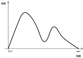
例えば、領域51の画像における階調のヒストグラムを図18に示し、階調の幅の拡張後の階調のヒストグラムを図19に示す。ここで、階調minは、領域51の画像における拡張前の階調の最小値である。階調maxは、領域51の画像における拡張前の階調の最大値である。階調min´は、再現可能な階調の最小値であって、ゼロである。階調max´は、再現可能な階調の最大値であって、再現可能な階調がNビットである場合には2N-1である。領域51の画像における拡張前の任意の階調は、階調maxおよび階調minを用いて、次の式のように拡張される。
拡張後の階調=(2N-1)×(拡張前の階調-min)/(max-min)
拡張後の階調=(2N-1)×(拡張前の階調-min)/(max-min)
印刷画像情報生成部29aは、S160の処理の後、領域51以外の画像における階調を反転させる(S161)。
次いで、印刷画像情報生成部29aは、S120およびS121(図7参照。)と同様のS162およびS163を実行して、図17に示す動作を終了する。
図20は、MFP20によって出力される印刷画像の一例を示す図である。
MFP20は、図17に示す動作において、領域51の画像における階調の幅を、再現可能な階調の幅に拡張する(S160)とともに、領域51以外の画像における階調を反転させる(S161)ので、図20に示すように、領域51の画像に関しては入力画像と同等の階調を再現することができる。
以上に説明したように、MFP20は、入力画像に基づいて印刷画像情報を生成する場合に、単一の色相における領域51の画像における明度の階調の幅を、単一の色相において再現可能な明度の階調の幅に拡張する(S160)ので、入力画像全体における階調を印刷画像によって適切に再現することができない場合であっても、入力画像のうち選択されている領域51の画像における階調を印刷画像によって適切に再現することができる。
MFP20は、単一の色相における領域51の画像における明度の階調の幅を、単一の色相において再現可能な明度の階調の幅に拡張する場合に、入力画像のうち領域51以外の画像における階調を反転させるので、入力画像のうち選択されている領域51の画像における階調を印刷画像において目立たせることができる。
本発明の画像形成システムは、上述した各実施の形態において、印刷画像情報生成部および印刷実行部の両方が画像形成装置によって実現されているが、印刷画像情報生成部および印刷実行部の少なくとも一部が印刷指示装置によって実現されても良い。例えば、印刷画像情報生成部を実現するための画像処理プログラムが印刷指示装置によって実行されることによって、印刷指示装置を印刷画像情報生成部として機能させても良い。
また、本発明の画像形成装置は、印刷画像情報生成部は、入力画像における輝度の階調の幅が印刷実行部によって再現可能な輝度の階調の幅を超えている場合に、入力画像における輝度の階調を単一の色相における明度の階調に変換して印刷画像情報を生成しても良い。
この構成により、本発明の画像形成装置は、入力画像における輝度の階調を印刷画像において輝度の階調として再現することができない場合に、入力画像における輝度の階調を印刷画像において単一の色相における明度の階調として再現するので、入力画像における階調を印刷画像によって適切に再現することができる。
また、本発明の画像形成装置は、印刷画像情報生成部は、印刷実行部によって出力可能な最高の濃度が特定の濃度未満である場合に、入力画像における輝度の階調を単一の色相における明度の階調に変換して印刷画像情報を生成しても良い。
この構成により、本発明の画像形成装置は、入力画像における輝度の階調を印刷画像において輝度の階調として再現する性能が低下している場合に、入力画像における輝度の階調を印刷画像において単一の色相における明度の階調として再現するので、入力画像における階調を印刷画像によって適切に再現することができる。
また、本発明の画像形成装置は、印刷画像情報生成部は、入力画像のうち選択されている特定の領域の画像における輝度の階調を単一の色相における明度の階調に変換する場合に、単一の色相における特定の領域の画像における明度の階調の幅を、印刷実行部によって再現可能な単一の色相における明度の階調の幅に拡張しても良い。
この構成により、本発明の画像形成装置は、入力画像に基づいて印刷画像情報を生成する場合に、単一の色相における特定の領域の画像における明度の階調の幅を、単一の色相において再現可能な明度の階調の幅に拡張するので、入力画像全体における階調を印刷画像によって適切に再現することができない場合であっても、入力画像のうち選択されている特定の領域の画像における階調を印刷画像によって適切に再現することができる。
また、本発明の画像形成装置は、印刷画像情報生成部は、単一の色相における特定の領域の画像における明度の階調の幅を、印刷実行部によって再現可能な単一の色相における明度の階調の幅に拡張する場合に、入力画像のうち特定の領域以外の画像における階調を反転させても良い。
この構成により、本発明の画像形成装置は、単一の色相における特定の領域の画像における明度の階調の幅を、単一の色相において再現可能な明度の階調の幅に拡張する場合に、入力画像のうち特定の領域以外の画像における階調を反転させるので、入力画像のうち選択されている特定の領域の画像における階調を印刷画像において目立たせることができる。
本発明の画像形成装置は、上述した各実施の形態においてMFPであるが、プリンター専用機など、MFP以外の画像形成装置であっても良い。
Claims (6)
- 入力画像に基づいて印刷画像のための印刷画像情報を生成する印刷画像情報生成部と、
前記印刷画像情報生成部によって生成された前記印刷画像情報に応じて前記印刷画像を出力する印刷実行部とを備え、
前記印刷画像情報生成部は、前記入力画像における輝度の階調を、2種類以上のプロセスカラーで表現される単一の色相における明度の階調に変換して前記印刷画像情報を生成することを特徴とする画像形成装置。 - 前記印刷画像情報生成部は、前記入力画像における輝度の階調の幅が前記印刷実行部によって再現可能な輝度の階調の幅を超えている場合に、前記入力画像における輝度の階調を前記単一の色相における明度の階調に変換して前記印刷画像情報を生成することを特徴とする請求項1に記載の画像形成装置。
- 前記印刷画像情報生成部は、前記印刷実行部によって出力可能な最高の濃度が特定の濃度未満である場合に、前記入力画像における輝度の階調を前記単一の色相における明度の階調に変換して前記印刷画像情報を生成することを特徴とする請求項1に記載の画像形成装置。
- 前記印刷画像情報生成部は、前記入力画像のうち選択されている特定の領域の画像における輝度の階調を前記単一の色相における明度の階調に変換する場合に、前記単一の色相における前記特定の領域の画像における明度の階調の幅を、前記印刷実行部によって再現可能な前記単一の色相における明度の階調の幅に拡張することを特徴とする請求項1に記載の画像形成装置。
- 前記印刷画像情報生成部は、前記単一の色相における前記特定の領域の画像における明度の階調の幅を、前記印刷実行部によって再現可能な前記単一の色相における明度の階調の幅に拡張する場合に、前記入力画像のうち前記特定の領域以外の画像における階調を反転させることを特徴とする請求項4に記載の画像形成装置。
- 入力画像に基づいて印刷画像のための印刷画像情報を生成する印刷画像情報生成部と、
前記印刷画像情報生成部によって生成された前記印刷画像情報に応じて前記印刷画像を出力する印刷実行部とを備え、
前記印刷画像情報生成部は、前記入力画像における輝度の階調を、2種類以上のプロセスカラーで表現される単一の色相における明度の階調に変換して前記印刷画像情報を生成することを特徴とする画像形成システム。
Applications Claiming Priority (2)
| Application Number | Priority Date | Filing Date | Title |
|---|---|---|---|
| JP2015-119022 | 2015-06-12 | ||
| JP2015119022A JP2018122432A (ja) | 2015-06-12 | 2015-06-12 | 画像形成装置、画像処理プログラムおよび画像形成システム |
Publications (1)
| Publication Number | Publication Date |
|---|---|
| WO2016199704A1 true WO2016199704A1 (ja) | 2016-12-15 |
Family
ID=57503189
Family Applications (1)
| Application Number | Title | Priority Date | Filing Date |
|---|---|---|---|
| PCT/JP2016/066709 Ceased WO2016199704A1 (ja) | 2015-06-12 | 2016-06-06 | 画像形成装置および画像形成システム |
Country Status (2)
| Country | Link |
|---|---|
| JP (1) | JP2018122432A (ja) |
| WO (1) | WO2016199704A1 (ja) |
Citations (3)
| Publication number | Priority date | Publication date | Assignee | Title |
|---|---|---|---|---|
| JP2007129439A (ja) * | 2005-11-02 | 2007-05-24 | Canon Inc | 色変換方法 |
| JP2015066014A (ja) * | 2013-09-26 | 2015-04-13 | 京セラドキュメントソリューションズ株式会社 | 画像処理装置及びプログラム並びに画像形成装置 |
| JP2015070338A (ja) * | 2013-09-26 | 2015-04-13 | 京セラドキュメントソリューションズ株式会社 | 画像処理装置及びプログラム |
-
2015
- 2015-06-12 JP JP2015119022A patent/JP2018122432A/ja active Pending
-
2016
- 2016-06-06 WO PCT/JP2016/066709 patent/WO2016199704A1/ja not_active Ceased
Patent Citations (3)
| Publication number | Priority date | Publication date | Assignee | Title |
|---|---|---|---|---|
| JP2007129439A (ja) * | 2005-11-02 | 2007-05-24 | Canon Inc | 色変換方法 |
| JP2015066014A (ja) * | 2013-09-26 | 2015-04-13 | 京セラドキュメントソリューションズ株式会社 | 画像処理装置及びプログラム並びに画像形成装置 |
| JP2015070338A (ja) * | 2013-09-26 | 2015-04-13 | 京セラドキュメントソリューションズ株式会社 | 画像処理装置及びプログラム |
Also Published As
| Publication number | Publication date |
|---|---|
| JP2018122432A (ja) | 2018-08-09 |
Similar Documents
| Publication | Publication Date | Title |
|---|---|---|
| US9189715B2 (en) | Image forming apparatus that prints out multi-gradation monochrome image maintaining gradation reproducibility, and image forming method | |
| US11750765B2 (en) | Performing color conversion that acquires a sample color included in second image data | |
| US20120020694A1 (en) | Image processing apparatus and image processing method | |
| US9218553B2 (en) | Image forming apparatus reproducing gradation based on hue instead of luminance, and image forming method | |
| JP7367159B2 (ja) | 画像処理装置、画像処理方法、および、プログラム | |
| US10523846B2 (en) | Performing color correction of image data where selection information is indicating that color correction is not to be performed | |
| JP6521250B2 (ja) | 画像形成装置、色変換プログラムおよび色変換方法 | |
| US11405524B2 (en) | Image forming apparatus, method of control, and program product for printing an image on a sheet based on a setting and counting a number of sheets on which scanned images determined to be chromatic or achromatic are printed | |
| US9989875B2 (en) | Image processing apparatus, image processing method, and storage medium | |
| US8368962B2 (en) | Color look up table adjusting apparatus, recording medium on which a color look up table adjusting program is recorded and color look up table adjusting system | |
| JP2018122432A (ja) | 画像形成装置、画像処理プログラムおよび画像形成システム | |
| JP2008271361A (ja) | 画像処理装置及び画像処理方法 | |
| JP2020168779A (ja) | 画像形成装置及びその制御方法、並びにプログラム | |
| JP2020057913A (ja) | 画像処理装置及び画像処理方法 | |
| JP2014099829A (ja) | 画像処理装置および画像処理方法ならびに画像処理を実行するプログラム | |
| JP2006094039A (ja) | 画像処理装置、画像処理方法及びプログラム | |
| JP2004146914A (ja) | インク消費量削減方法,インク消費量削減装置およびインク消費量削減プログラム | |
| JP4793409B2 (ja) | 画像評価装置及びプログラム | |
| JP2003250045A (ja) | プリンタ更正装置及びその制御方法 | |
| JP6169008B2 (ja) | 画像形成装置 | |
| JP6212090B2 (ja) | 画像形成装置及び画像形成方法 | |
| US20240364836A1 (en) | Profile editing apparatus, method for controlling profile editing apparatus, and storage medium | |
| JP7614854B2 (ja) | 画像処理装置、画像処理方法及びプログラム | |
| JP5957989B2 (ja) | 画像確認装置、画像形成システムおよびプログラム | |
| JP2009232229A (ja) | 画像処理システム、画像処理プログラム及び画像処理方法 |
Legal Events
| Date | Code | Title | Description |
|---|---|---|---|
| 121 | Ep: the epo has been informed by wipo that ep was designated in this application |
Ref document number: 16807411 Country of ref document: EP Kind code of ref document: A1 |
|
| NENP | Non-entry into the national phase |
Ref country code: DE |
|
| 122 | Ep: pct application non-entry in european phase |
Ref document number: 16807411 Country of ref document: EP Kind code of ref document: A1 |
|
| NENP | Non-entry into the national phase |
Ref country code: JP |