WO2016199213A1 - 画像取得装置、およびそれに用いる位置情報取得方法 - Google Patents
画像取得装置、およびそれに用いる位置情報取得方法 Download PDFInfo
- Publication number
- WO2016199213A1 WO2016199213A1 PCT/JP2015/066537 JP2015066537W WO2016199213A1 WO 2016199213 A1 WO2016199213 A1 WO 2016199213A1 JP 2015066537 W JP2015066537 W JP 2015066537W WO 2016199213 A1 WO2016199213 A1 WO 2016199213A1
- Authority
- WO
- WIPO (PCT)
- Prior art keywords
- position information
- image
- function
- information acquisition
- acquisition
- Prior art date
Links
Images


Classifications
-
- G—PHYSICS
- G03—PHOTOGRAPHY; CINEMATOGRAPHY; ANALOGOUS TECHNIQUES USING WAVES OTHER THAN OPTICAL WAVES; ELECTROGRAPHY; HOLOGRAPHY
- G03B—APPARATUS OR ARRANGEMENTS FOR TAKING PHOTOGRAPHS OR FOR PROJECTING OR VIEWING THEM; APPARATUS OR ARRANGEMENTS EMPLOYING ANALOGOUS TECHNIQUES USING WAVES OTHER THAN OPTICAL WAVES; ACCESSORIES THEREFOR
- G03B17/00—Details of cameras or camera bodies; Accessories therefor
- G03B17/24—Details of cameras or camera bodies; Accessories therefor with means for separately producing marks on the film, e.g. title, time of exposure
-
- H—ELECTRICITY
- H04—ELECTRIC COMMUNICATION TECHNIQUE
- H04N—PICTORIAL COMMUNICATION, e.g. TELEVISION
- H04N23/00—Cameras or camera modules comprising electronic image sensors; Control thereof
Definitions
- the present invention relates to an image acquisition apparatus, and more particularly to a camera that captures and stores an image, and more particularly to an apparatus that has a function of acquiring the current position of the camera at the time of shooting and storing it together with the captured image.
- a two-dimensional captured image is obtained by projecting an image of a subject through a lens onto a camera sensor, which is an assembly of multiple pixels composed of semiconductors, and measuring the amount of light emitted for each pixel.
- Digital cameras are popular.
- An image shot with such a camera is compressed by a predetermined image compression method so that the size of the image file becomes small.
- a predetermined image compression method for example, an image file in which attribute information called exif (exchangeable image file format) is compressed To construct one image file.
- This attribute information includes information about the shooting conditions of image data such as the camera and lens that were shot, the focal length and aperture value of the lens, shutter speed, and sensor sensitivity, as well as the shooting position (on the earth acquired by a method such as GPS). Coordinate data) can be acquired and stored in the image data.
- Patent Document 1 Japanese Patent Application Laid-Open No. 2011-030021
- a position acquisition function using GPS is installed in a camera, and in addition to the current position at the time of shooting, the camera periodically acquires position information about the movement trajectory when the user moves with the camera.
- the technique acquired by this is disclosed. According to this technique, information on the artificial satellite can be received, and information on the current position can be calculated according to the operation schedule of the artificial satellite at the current time in the information, particularly when the position acquisition function by GPS is initially activated. Therefore, the camera's current position can be calculated at any position on the earth as long as it can receive radio waves from artificial satellites. Useful for obtaining current location information.
- the position acquisition function When the position acquisition function is operating continuously, satellite orbit information has already been received, and by using a difference calculation over time, etc., it will be continuous at short intervals (less than 1 second). Thus, the current position coordinates can be calculated.
- the time required for this is at least several tens of seconds to several tens of seconds. May take minutes. Therefore, when the GPS is operated for the first time when the camera is turned on, particularly in the case of shooting immediately after the power is turned on, there is a problem that accurate position information at the moment of shooting cannot be obtained.
- An object of the present invention is to provide a photographing device that stores a photographing position in association with photographed image data.
- the present invention includes a plurality of means for solving the above problems.
- the present invention is an image acquisition apparatus having a position information acquisition function and an image information acquisition function.
- An image to be stored by adding the position information of the image acquisition device acquired by the position information acquisition function to the image information acquired by the image information acquisition function. It has an information storage function, and the position information acquisition function acquires the position information with a first time interval from the time when the battery is attached to the image acquisition device, and operates the power switch or the image information acquisition function.
- the acquisition interval of the position information acquisition function is changed from the first time interval according to the operation.
- the coordinates of the place where the image was taken are acquired as accurately as possible and added to the taken image, while reducing battery consumption, longer camera operation and no longer possible due to battery consumption. Can be suppressed.
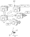
- FIG. 1 is a configuration diagram of a communication system including an image acquisition device having a position information acquisition function in Embodiment 1.
- FIG. 3 is an explanatory diagram showing the contents of an image information file handled by an image acquisition device having a position information acquisition function in Embodiment 1.
- 1 is a block diagram of an image acquisition device having a position information acquisition function in Embodiment 1.
- FIG. 6 is an explanatory diagram illustrating a relationship between camera operation and remaining battery power when position detection is always performed while the camera power source that is the premise of Embodiment 1 is ON.
- FIG. 6 is an explanatory diagram illustrating a relationship between a camera operation of an image acquisition apparatus having a position information detection function and a remaining battery power in Embodiment 1. It is explanatory drawing which shows the state of a camera useful as a trigger for changing the position detection timing by the image acquisition apparatus which has a position information detection function in Example 2.
- FIG. 10 is an explanatory diagram illustrating a position information acquisition interval of an image acquisition apparatus having a position information detection function according to a third embodiment.
- FIG. 10 is an explanatory diagram illustrating a position information acquisition interval of an image acquisition apparatus having a position information detection function according to a fourth embodiment.
- FIG. 10 is an explanatory diagram illustrating an example of a program for controlling the operation of an image acquisition apparatus having a position information detection function according to a fifth embodiment.
- FIG. 1 is a configuration diagram of a communication system including an image acquisition device having a position information acquisition function and an image information acquisition function in the present embodiment.
- a digital camera (1000) is an image acquisition device having the functions of this embodiment.
- the digital camera (1000) is a power switch 1010 that shifts the digital camera to a shooting enabled state, which is an image information acquisition function, a shutter button 1030 for shooting, and a GPS that receives radio waves from GPS satellites and performs processing such as decoding Unit 1020 is installed.
- This digital camera 1000 can receive radio waves from a plurality of GPS artificial satellites of GPS satellite A (1040), GPS satellite B (1041), and GPS satellite C (1042) by the GPS unit 1020, and at least three or more. Based on the accurate time obtained by the atomic clock of the artificial satellite obtained from the received information, and the coordinates of each artificial satellite at that time (orbital orbit information of the artificial satellite) By using the distance to each artificial satellite obtained by information and the time taken from the transmission to reception of the radio wave (the propagation speed of the radio wave is 300,000 km / second, which is the same as the speed of light), Can be calculated.
- the digital camera 1000 can identify the current position by receiving radio waves from the wireless LAN router 1050 or a mobile phone base station (not shown) as radio waves that can be determined as position information from a predetermined narrow area. It is also possible to take a picture by receiving the current position of the portable information terminal obtained by the portable information terminal 1060 that can acquire position information by GPS nearby by short-range wireless communication such as Bluetooth (registered trademark) The position information can be acquired by handling the received position coordinates as the current position.
- acquisition of position information using GPS is performed in two states: when the camera is not used (leaved) and when shooting is repeated using the camera.
- the time interval to acquire the current position of the camera was changed according to the function.
- FIG. 2 is an explanatory diagram showing the contents of an image information file handled by an image acquisition apparatus having a position information acquisition function and an image information acquisition function in this embodiment.
- an image file 2010 is composed of the following information data.
- the image file 2010 includes shooting information A (2010) indicating the type of information related to the stored shooting image 2000, shooting information B (2020) that is actual data of each information indicated by the shooting information A (2010), shooting information
- the thumbnail image 2040 reduced from the image 2000 and the captured image 2000 are combined with a transform / encoding method such as discrete cosine transform and Huffman coding to compress the information amount and save the data amount. And compressed image data 2050 with improved reading efficiency.
- information about the captured image 2000 shown in the shooting information B (2030) includes, for example, a shooting date 2031, a storage date 2032, a camera name 2033 used for shooting, a lens name 2034 used for shooting, a shutter speed 2035, and an aperture value.
- 2036 film mode 2037 (for example, reversal mode, black and white mode, etc.), ISO sensitivity 2038 representing a gain for amplifying sensor output at the time of shooting, and shooting location coordinates 2039 handled in this embodiment.
- FIG. 3 is a block diagram of an image acquisition apparatus having a position information acquisition function and an image information acquisition function in the present embodiment.
- the digital camera 3170 in the present embodiment is basically configured as a computer system as the embodiment. That is, as shown in FIG. 3, the CPU 3000 is a central information processing apparatus, and various types of hardware are connected to the bus 3001.
- Shutter button 3010 used when shooting with a camera, a camera sensor 3020 that converts an optical image collected by a lens (not shown) into an electrical signal, a signal processing DSP 3030 that performs signal processing of the camera sensor 3020, and RGB obtained by the signal processing DSP
- An encoder / decoder 3040 that compresses the constructed video signal using a compression method such as discrete cosine transform or Huffman coding (the encoder / decoder has a function to compress not only a captured still image but also a moving image)
- the camera sensor 3020, the signal processing DSP 3030, and the encoder / decoder 3040 are not only connected to the bus, but also output signals from the camera sensor 3020 directly to the signal processing DSP 3030, encoder / decoder.
- the video signal may be processed by being sent to 3040. In this case, a large video signal should not be passed through the bus 3001. Therefore, without the bus 3001 image signal occupies, while performing compression processing from the photographing
- the GPS unit 3050 that acquires the current position of the digital camera 3170
- the G sensor 3060 that measures the direction of the camera, the acceleration that occurs when the camera moves or changes direction, the camera and mobile terminal device, etc.
- Bluetooth3070 for short-range wireless communication with external devices
- wireless LAN3080 for wireless communication between external devices such as cameras and mobile terminal devices, and acquisition of current location using signals of wireless communication base stations
- camera Flash memory 3090 that stores the overall control program and basic constants
- SD-RAM 3100 that stores GPS satellite orbit information 3012 and GPS position information 3101 that are the work memory for program execution and are updated sequentially, and image information that is stored during shooting Watch the subject image received by the camera sensor at the time of shooting.
- EVF / LCD 3120 to be used, for example, a camera operation switch 3130 for performing various camera operations such as changing the setting contents of the camera, an external memory 3141 for storing captured and compressed image data, and an external memory I for connecting to the camera / F3140, infrared light receiving unit 3151 that receives external instructions such as camera shutter operation with an infrared remote control, remote control I / F3150 that converts the output signal into digital data for use as a camera control signal, and There is an attitude change detection SW3160 using a mercury switch that detects that the attitude of the camera has changed.
- FIG. 4 is a reference example as a premise of the present embodiment. That is, it is an explanatory diagram showing the relationship between the camera operation and the remaining power of the battery when the position detection by GPS is always performed while the power switch of the camera is ON.
- a graph indicated by a power supply 4000 is a graph showing the relationship between ON / OFF of the power switch of the camera and time t (4040), with the high level indicating the ON state and the low level indicating the OFF state.
- the horizontal axis indicates time t (4040)
- the high level indicates the GPS position acquisition operation ON state
- the low level indicates the OFF state.
- the horizontal axis indicates the shooting operation ON state and the low level is OFF state with respect to time t (4040).
- the graph indicated by the remaining power 4030 is a graph showing the relationship with the time t (4040) of the remaining power of the battery.
- the camera always performs position detection by GPS while the power switch is turned on.
- the power is turned ON once at 4001.
- the general GPS camera in this embodiment acquires the position information when the power is turned on, the GPS position acquisition 4010 continues even after the power is turned off.
- the current position is calculated by using the distance to the satellite.
- time T 1 (4011) is required. This process continues even after the camera power supply 4000 is turned off, and the GPS position detection circuit consumes power, and when the position information is obtained, all the cameras other than the clock are turned off.
- This position information acquisition may be started at the same time when the battery is attached to the camera and power can be supplied without first turning on the power (4001).
- the power switch of the camera is turned ON again for actual shooting (4002), and the camera is brought into an operable state.
- an image file of the video shot at time 4021 is generated.
- the current position at the time of shooting is the same as when the power is turned on 4001, and all processing for acquiring position information is performed. Therefore, the processing takes time T 1 (4011), specifically 30 seconds to 1 minute, for example. It takes a degree (4004). Since the result is entered in the image file, the current position acquisition time is delayed by T 1 as indicated by 4014 with respect to the photographing time.
- the position information is acquired at T 2 (4012), which is much shorter than the time T 1 (4011) after the first position information acquisition. Therefore, the position information can be updated in a cycle of time ⁇ t 1 (4013), specifically, for example, once every few seconds. Therefore, for example, when an image file of a video shot at time 4022 is generated, position information acquired at a timing with almost no time difference such as 4015 can be used as added position information. It is possible to reduce the error of the current position information accompanying the movement of the camera.
- the remaining power of the battery used in the camera that performs these operations will be described as remaining power 4030. If the discharge due to natural leakage when not in use is ignored, the remaining power graph does not change and the waveform is horizontal when the camera power switch is turned off and the location information acquisition operation by GPS is not performed. .
- the remaining power graph in this embodiment is obtained by performing the signal processing and compression processing described with reference to FIG. 3 while the camera's power switch is turned on, while acquiring position information by GPS, and for the captured image. During storage in memory, the remaining power decreases with each sum. If this decrease is steep or the time is long, the battery power consumption of the camera increases, and a phenomenon occurs in which the time in which the camera can be used is shortened.
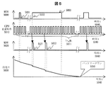
- FIG. 5 shows another reference example which is a premise of the present embodiment. That is, it is an explanatory diagram showing the relationship between the camera operation and the remaining battery power when the position detection by GPS is always performed while the battery is attached to the camera, regardless of whether the power switch of the camera is ON or OFF.
- FIG. 5 shows a camera power supply 5000 indicating ON / OFF of the power switch of the camera, a GPS position acquisition 5010 indicating ON / OFF of the GPS position acquisition operation, and a shooting indicating ON / OFF of the shooting operation, as in FIG.
- a graph of the remaining power 5030 showing the relationship between 5020 and the time of the remaining power of the battery is shown.
- FIG. 5 shows another reference example which is a premise of the present embodiment. That is, it is an explanatory diagram showing the relationship between the camera operation and the remaining battery power when the position detection by GPS is always performed while the battery is attached to the camera, regardless of whether the power switch of the camera is ON or OFF.
- FIG. 5 shows a
- ON / OFF of the power source 5000 and photographing 5020 are the same as the power source 4000 and photographing 4020 shown in FIG.
- GPS position information acquisition 5010 is always the same as ⁇ t 1 (5011), which is the same as the time ⁇ t 1 (4013) shown in FIG.
- the position information is updated in a cycle of once every few seconds.
- the initial operation of GPS does not require a long time like T 1 (4011) in FIG. 4, so it is acquired within a time range of once every few seconds at the maximum for each shooting (5021, 5022, etc.).
- the recorded position information is recorded in the captured image file. For this reason, an error in the relationship between the shooting timing and the current position is reduced.
- the remaining power 5030 of the battery used in the camera that performs these operations is not always turned off and is always operating as compared to the remaining power 4030 of FIG.
- the remaining power of the camera continues to decrease.
- the time left after shooting is long, the possibility of causing the battery down 5050 is extremely increased. Therefore, even if a camera that is normally left unattended is used suddenly, it cannot be operated, and the most basic and indispensable function of the camera can be achieved. It becomes difficult.
- FIG. 6 is an explanatory diagram showing the relationship between the camera operation of the image acquisition device having the position information detection function and the remaining battery power in this embodiment.
- FIG. 6 is similar to FIGS. 5 and 4, the camera power source 6000 indicating ON / OFF of the power switch of the camera, the GPS position acquisition 6010 indicating ON / OFF of the GPS position acquisition operation, and the ON / OFF of the shooting operation.
- a graph of the remaining power 6030 showing the relationship between the shooting 6020 indicating the time and the time of the remaining power of the battery is shown.
- ON / OFF of the camera power source 6000 and the photographing operation 6020 are the same as the camera power sources 4000 and 5000 and the photographing operations 4020 and 5020 shown in FIGS. 4 and 5.
- the GPS position acquisition 6010 continues to operate while the battery is attached to the camera regardless of whether the camera power switch is turned on or off, but depending on the timing of the camera power supply 6000 and the shooting 6020, It is characterized by switching the acquisition interval of information acquisition.
- FIG. 6 first, in a state where the camera has been left for a while (left), GPS position acquisition is not operated as in the embodiment of FIG. Therefore, in this state, the battery is not consumed as shown in FIG. 5, and the remaining power 6030 of the battery continues to be maintained without being reduced, except for natural leakage. Then, at the timing of using the camera, such as when going out with a normal camera, turn on the camera once (6001) and check the subject monitor and AF operations using the viewfinder. GPS position acquisition is performed at the timing when the power switch of this camera is turned on. In this state, basic data such as the orbit and time of the artificial satellite of this day is received.
- the current position detection is continued by providing a time interval in which basic data such as time and time may not be re-acquired.
- the state is switched to a state in which the camera is powered on for shooting purposes.
- the current position can be acquired within a range that does not require reacquisition of the satellite's orbit and time.
- the relationship between the shooting time and the current position can be accurately maintained with minimal error.
- the reacquisition is not necessary from the timing of periodic position acquisition by GPS.
- the camera is left for a longer period of time (for example, 10 hours), the camera is deemed to have been used and the GPS position acquisition is completely stopped. In this way, by dynamically changing the GPS position acquisition interval according to the camera handling status by the user, the battery residual power is minimized while keeping the relationship error between the captured image and the shooting position to a minimum. It becomes possible to do.
- triggers such as shooting, that is, the timing of pressing the shutter button or the timing of AF lock by half-pressing the shutter button.
- the relationship between the captured image and the acquired position information includes the satellite orbit by GPS and the time of day.
- An error in the time taken for acquisition occurs.
- shooting information B (2030) in FIG. 2 is provided with an area for storing an error occurrence and a numerical value of the difference between the shooting time and the position information acquisition time
- the image is displayed on a camera or a playback device.
- it is possible to confirm the presence or absence of miscalculation by superimposing the icon or numerical value indicating the occurrence of this error on the thumbnail list at the time of playback or the image displayed in full screen, or by viewing the attributes of the image file.
- the remaining power of the battery is measured by measuring the amount of power discharged from the battery as the camera consumes the battery in addition to measuring the voltage at the power supply terminal of the battery. Any other method may be used such as a value obtained by subtracting (mAh unit or the like) as the remaining power.
- the present embodiment is an image acquisition apparatus having a position information acquisition function and an image information acquisition function.
- the image acquisition apparatus is operated by a battery and is operated by operating a power switch.
- the image information storage function for storing the position information of the image acquisition device acquired by the position information acquisition function in addition to the image information acquired by the image information acquisition function.
- the position information is acquired at a first time interval from the time when the battery is mounted on the image acquisition device, and the position information acquisition function is acquired in accordance with the operation of the power switch or the image information acquisition function. Is changed from the first time interval.
- a position information acquisition method for an image acquisition apparatus having a position information acquisition function and an image information acquisition function
- the image acquisition device is operated by a battery and transitions to a state in which it operates by operating a power switch, and at a position information acquisition interval of a first time interval from the time when the battery is attached to the image acquisition device.
- Position information acquisition of the image acquisition device is performed, and the position information acquisition interval is changed from the first time interval in response to an operation of a power switch or an operation of acquiring image information.
- the coordinates of the shooting location are obtained as accurately as possible and added to the shot image, while reducing battery consumption, preventing longer camera operation and shooting impossibility due to battery consumption. I can do it.
- FIG. 7 is an explanatory diagram showing the state of a camera useful as a trigger for changing the GPS position detection timing by the image acquisition device having a position information detection function in the present embodiment.
- FIG. 7A shows an example of the state of the camera.
- the camera is turned on at the time of shooting, the viewfinder is looked into, the subject is focused by AF, and the shutter is released.
- (7020) is the basic operation, but in other cases, for example, when it is not in use, the so-called neglected time elapsed (7010), or the camera operates Although there is a state where the current position frequently changes (7030) while traveling, etc., and there is a state (7040) where the posture of the camera changes due to the operation of picking up the camera that is placed .
- Lapse of time means that the camera is in a neglected state, so it is necessary to prevent the battery from being consumed by extending the GPS position detection interval or cutting it completely.
- the other items 7020, 7030, and 7040 are important information for the user to detect in advance the signs of using or actually using the camera. The electrical operation of the camera by detecting these states will be described with reference to FIGS.
- FIG. 7B is an example of a device that easily detects the posture change (7040) shown in FIG. 7A with low power consumption.
- Mercury particles 7051 are placed in a tube-shaped member, and the mercury particles 7051 move through the tube-shaped member by inclination.
- An electrode 7052 is inserted into the tube-shaped member, and the electrode is short-circuited when mercury particles 7051 are present at that location.
- a high / low switching trigger signal is generated by ON / OFF of the electrode.
- an acceleration detection method using a strain gauge, a G sensor, or the like may be used as a method for detecting the posture of the camera.
- the camera attitude change can be taken out as a signal line high / low change without consuming power. It is useful as a device that detects in advance that “uses”.
- the installation location and direction of the posture change detection SW (7050) depends on the shape of the camera, but it can be used by users in various situations, such as being placed on a shelf or sleeping in a camera bag.
- the posture change detection SW (7050) may be installed at an optimal position where the signal line changes when the camera holds the camera.
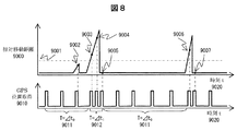
- FIG. 8 is an explanatory diagram showing the position information acquisition interval of the image acquisition apparatus having the position information detection function in the present embodiment.
- the interval for detecting the position information is changed using the power ON / OFF of the camera and the timing of shooting, whereas in the present embodiment, the current position of the camera has changed.
- the interval for detecting the position information is changed according to the distance.
- the distance between the two position information detected at the time interval is detected, that is, the position information is detected according to the relative movement distance. It is characterized by changing the time interval.
- Position information detection accuracy by GPS may cause measurement errors under various conditions, such as whether there are high buildings in the vicinity and how many artificial satellites are received at the time of measurement.
- a measurement error that is normally considered is determined to be noise, and the distance between two consecutive position information is a threshold that is equal to or greater than the maximum value of the noise. If it is within the distance (9001) set as hold, it is not determined that the camera has moved (9002), and the time interval for position acquisition is not changed.
- the position information detection time interval is continuously set after that and the position information is continuously detected.
- T ⁇ t 0 (9011) and ⁇ t 1 (9012)
- T ⁇ t 0 (9011) and ⁇ t 1 (9012)
- the time interval may be dynamically changed so that a time error does not occur in the acquired value. This method is effective, for example, when a camera operation such as taking a picture of a landscape is performed while traveling on a highway by a car or traveling by train.
- FIG. 9 is an explanatory diagram showing the position information acquisition interval of the image acquisition apparatus having the position information detection function in the present embodiment. 6 uses the camera power ON / OFF and shooting timing, and FIG. 8 changes the interval for detecting position information using the distance information of two consecutive position information measurement results.
- the change in the detection time interval of the position information is detected by detecting that the user has moved the direction of the camera for taking a picture, which is described as “camera posture change” in FIG. It is a feature.
- T ⁇ t 0 (10011)
- Position information is acquired before turning on, and an accurate current position corresponding to shooting immediately after the power is turned on can be acquired.
- FIG. 9B is a simple circuit example for collectively handling the conditions for changing the position information acquisition intervals in FIGS. 8 and 9A.
- the electrode of the posture change detection SW shown in FIG. 7B switches between short-circuiting and releasing according to the position of the mercury particles inside. By outputting the switching point of this signal as a pulse signal, it can be detected as an event that the camera has undergone some posture change in any direction.
- a signal indicating this event is an attitude change detection SW trigger 10040.
- the conditions for changing the position information acquisition interval include the power switch operation and the shutter button operation described in the explanation of FIG. 6, and these are also event signals of power ON / shutter trigger 10030.
- the event signal may be that the camera has been removed from the camera. Further, by performing a logical OR (10040) of these, it becomes possible to collectively use the position information acquisition interval as one event of the position acquisition trigger 10050.
- the event is not limited to the above.
- the switch provided near the optical viewfinder is pushed.
- the switch placed at an appropriate position on the body is pushed. Any other method may be used as long as it is a method for detecting in advance that the user is taking a picture, and when these are combined to satisfy a specific condition, “the user takes a picture.
- An operation method of “detecting what to do in advance” may be used.
- FIG. 10 is an explanatory diagram showing an example of a program for controlling a specific operation of the camera of the image acquisition apparatus having the position information detection function in the present embodiment.
- a program that actually operates on the camera a loop for counting a plurality of times is run to unconditionally reduce the power consumption of the CPU operation.
- OS an event-driven operating system
- the event-driven OS is particularly effective as an OS for devices that want to perform power-saving operations.
- This OS is not a concept in which a program operates according to a flow chart of one row, but a plurality of programs (hereinafter referred to as tasks) having various functions always exist on the memory and wait for an operation instruction.
- each function is, for example, when an event occurs when a button is pressed. Recognizes the occurrence of an event as interrupt information to the CPU, and executes a task that performs processing corresponding to the button according to the interrupt type and priority.
- TASK_INIT (11000) which is an initial value setting task, is called from the OS to set the initial value of this program to be executed when the camera is started after the power is completely turned off (with the battery removed).
- TASK_INIT (11000) has the right to use the CPU when called from the OS, and as an initialization process to be executed, the initial value of the position information acquisition time interval and the position information to be performed in the set position information acquisition time interval Set the number of acquisition processes.
- the OS calls various initial setting tasks to make each camera hardware operate normally in the same way as TASK_INIT (11000), and all initial settings are completed. By the way, it returns to the state of the standby (do nothing) task and waits for an interrupt due to the next event.
- TASK_CLOCK (11100), which is a one time / second PIN (trigger) output task, will be described.
- TASK_CLOCK 11100
- TASK_T 11300
- TASK_T 11300
- TASK_T 11300
- TASK_TRIG 11200 which is a position acquisition task
- TASK_TRIG 11200
- Fig. 9 B
- a position acquisition trigger indicating that the user has previously sensed that the camera will be used for shooting as an interrupt to the CPU, and the user takes a picture.
- TASK_GPS (11600)
- TASK_GPS (11600)
- the CPU usage right is passed to TASK_GPS (11600)
- TASK_GPS (11600) ends the CPU usage right is returned to TASK_T2 (11400), and TASK_T2 (11400) similarly returns the CPU usage right to the OS and enters a standby state.
- TASK_T (11300) which is a periodic position information acquisition task
- TASK_T (11300) has a function to call TASK_GPS (11600), which is a position acquisition task, according to a given position information acquisition time interval and the number of times.
- This process is the same as the operation according to the initial value set by TASK_INIT (11100), except for the L count.
- TASK_T2 (11400) is executed
- execute the initialization process again with TASK_INIT (10000), set the initial value of the position information acquisition time interval and the number of times the position information acquisition process is performed in the set position information acquisition time interval, and use the CPU To return to the standby state.
- TASK_GPS 11600
- This task receives GPS satellite radio waves (11601), and if radio waves can be received, the current position and orbit information of each artificial satellite necessary to calculate the current position information carried by the radio waves. , And receive the exact time handled by the GPS satellite (11603). This reception is repeated until all the information is received (11604). In particular, the initial reception takes time because it receives not only the propagation distance of the currently received radio wave but also the above-mentioned orbit information.
- the loop is repeated until the reception is completed.
- this reception part is also driven by the event-driven receiver and its output. Until the data is completely extracted from the buffer, the CPU usage right is returned to the higher-level task each time, and it is originally desirable to enter a standby state. All basic operations including camera power-on cannot be performed because all CPU resources are allocated to the 11604 loop in TASK_GPS (11600)).
- the position coordinates in the unit of the latitude and longitude of the earth are calculated using it (11605). Then, the coordinate value is passed to the caller task and the shooting / image information compression / attribute information addition task (not shown) that actually needs the information. Enters a waiting state.
- the GPS built-in portable information terminal GPS A system that manages the location information measured by the above and the unique ID of the wireless LAN router is uploaded to the cloud, and the information is managed.
- the connected device can know its current position as a rough position.
- image data can be transmitted to the device using Bluetooth.
- the captured images can be uploaded to a social network service (hereinafter referred to as SNS) or sent to an acquaintance by e-mail.
- SNS social network service
- the camera can know its current position information. In this case, even when the camera does not have a function of measuring the current position information, it can be used as a means for knowing the current position information.
Abstract
デジタルカメラにおいて、GPSを用いた位置取得機能の初期起動時は時間がかかり、撮影した瞬間の正確な位置情報を取得出来ない場合がある。また、常に位置取得機能を動作させると、バッテリー消費により撮影ができないという課題がある。 上記課題を解決するために、位置情報の取得機能と画像情報の取得機能を有する画像取得装置であって、画像取得装置は、バッテリーにより動作し、電源スイッチを操作することで動作する状態に遷移し、位置情報の取得機能により取得した画像取得装置の位置情報を、画像情報の取得機能により取得した画像情報に付加して保存する画像情報保存機能を有し、位置情報の取得機能は、バッテリーを画像取得装置に装着した時点から第1の時間間隔を以って位置情報取得を行い、電源スイッチの操作もしくは画像情報の取得機能の操作に応じて、位置情報の取得機能の取得間隔を第1の時間間隔から変化させる構成とする。
Description
本発明は、画像取得装置に係り、特に画像を撮影、保存するカメラに関し、撮影時のカメラの現在位置を取得し、撮影した画像と共に保存する機能を有する装置に関する。
被写体の画像を半導体により構成される多画素の集合体であるカメラセンサに、レンズを通して画像投射させ、各画素毎に照射された光の量を測定することにより、二次元の撮像画像を取得するデジタル方式のカメラが普及している。
このようなカメラで撮影した画像は、所定の画像圧縮方法により、その画像ファイルのサイズが小さくなるように圧縮されるが、同時に例えばexif(exchangeable image file format)と呼ばれる属性情報を圧縮した画像ファイルに付加して、一つの画像ファイルを構築する。
この属性情報には、撮影したカメラやレンズ、レンズの焦点距離や絞り値、シャッター速度、センサ感度等の画像データの撮影条件に関する情報に加え、撮影した位置(GPS等の方法により取得した地球上の座標データ)を取得し、前記画像データに内包して保存することが出来る。
ここで、機器の現在位置情報の取得には、GPS(Global Positioning System)を用いた方法が最も一般的であり、これに関する先行技術として特開2011-030021号公報(特許文献1)がある。特許文献1には、GPSによる位置取得機能をカメラに搭載し、撮影時点の現在位置の他に、カメラを持ってユーザーが移動したときの移動軌跡を、カメラが定期的に位置情報を取得することにより取得する技術が開示されている。この技術によれば、特にGPSによる位置取得機能の初期起動時に、人工衛星の情報を受信し、その情報にある現在時刻における人工衛星の運行スケジュールに従って、現在位置の情報を算出することが出来る。よって、地球上の如何なる位置でも、人工衛星からの電波を受信出来る条件であれば、カメラの現在位置を算出することが出来、地図や景色などの情報に頼ることなく、簡便に正確なカメラの現在位置情報を得るのに有用である。
GPSを用いた位置取得機能を用いた場合、以下の問題点がある。
位置取得機能が常時連続して動作しているときは、人工衛星の軌道情報を既に受信しており、時間経過に伴う差分計算などを用いることで、短時間(1秒以下)の間隔で連続して現在位置座標を算出することが可能である。しかし、初期起動時は、まず人工衛星の軌道情報や、人工衛星から発信される正確な時刻情報を用いて、初期位置の算出を行う必要があり、これに要する時間は少なくとも数十秒から数分かかることがある。そのため、カメラの電源を入れるときにGPSを初めて動作させた場合は、特に電源を入れた直後の撮影の場合は、撮影した瞬間の正確な位置情報を取得することが出来ないという問題がある。
また、カメラは携帯機器なのでバッテリーにより動作している。このため前記課題を解決するために、常時位置取得機能を動作させた場合、撮影時は勿論、カメラを単に携行や放置している状態でもバッテリーを消費しており、カメラとして一番基本的且つ必須である、如何なる状態でも撮影が可能であるという目的を、カメラの撮影に係る動作以外の要因にて達成出来ないという事象が発生する。
本発明の目的は、バッテリーで駆動するカメラの撮影に係る動作以外の状態でのバッテリー消費を抑え、且つ撮影を行う際に、撮影時刻と現在位置測定時刻を可能な限り近づけることにより、正確な撮影位置を撮影した画像データに付随して保存する撮影装置を提供することである。
本発明の目的は、バッテリーで駆動するカメラの撮影に係る動作以外の状態でのバッテリー消費を抑え、且つ撮影を行う際に、撮影時刻と現在位置測定時刻を可能な限り近づけることにより、正確な撮影位置を撮影した画像データに付随して保存する撮影装置を提供することである。
上記課題を解決するために、例えば請求の範囲に記載の構成を採用する。本発明は上記課題を解決する手段を複数含んでいるが、その一例を挙げるならば、位置情報の取得機能と画像情報の取得機能を有する画像取得装置であって、画像取得装置は、バッテリーにより動作し、電源スイッチを操作することで動作する状態に遷移し、位置情報の取得機能により取得した画像取得装置の位置情報を、画像情報の取得機能により取得した画像情報に付加して保存する画像情報保存機能を有し、位置情報の取得機能は、バッテリーを画像取得装置に装着した時点から第1の時間間隔を以って位置情報取得を行い、電源スイッチの操作もしくは画像情報の取得機能の操作に応じて、位置情報の取得機能の取得間隔を第1の時間間隔から変化させる構成とする。
本発明によれば、撮影した場所の座標を可能な限り正確に取得して、撮影した画像に付加しつつ、バッテリー消耗を抑え、より長時間なカメラの運用と、バッテリー消耗による撮影不可となることを抑えることが出来る。
以下、本発明の実施例について図面を用いて説明する。
図1は、本実施例における位置情報の取得機能と画像情報の取得機能を有する画像取得装置を含む通信システムの構成図である。図1において、デジタルカメラ(1000)が、本実施例の機能を有する画像取得装置である。デジタルカメラ(1000)は、デジタルカメラを画像情報の取得機能である撮影可能状態に移行させる電源スイッチ1010、撮影を行うシャッターボタン1030、そしてGPS衛星からの電波を受信しデコード等の処理を行うGPSユニット1020を搭載している。
このデジタルカメラ1000は、GPSユニット1020により、GPS衛星A(1040)、GPS衛星B(1041)、GPS衛星C(1042)の複数のGPS人工衛星からの電波を受信可能であり、少なくとも3つ以上の人工衛星からの電波を受信し、受信した情報から得られる、人工衛星が有する原子時計により得られた正確な時刻、および各人工衛星の当該時刻における座標(人工衛星の軌道周回情報)を基礎情報とし、電波の発信から受信までにかかる時間(電波の伝播速度は、光の速度と同じ30万km/秒である)により得られた各人工衛星までの距離を用いることで、現在位置を算出することが出来る。
また、デジタルカメラ1000は、無線LANルータ1050や、図示しない携帯電話基地局からの電波を用いて、所定の狭領域を位置情報として判定可能な電波として受信することにより現在位置をおよそ特定することも可能であり、さらに近隣にGPSによる位置情報を取得可能な携帯情報端末1060により得られた携帯情報端末の現在位置をBluetooth(登録商標)等の短距離無線通信により受信することで、撮影した時の現在位置として受信した位置座標を扱うことにより、位置情報を取得することも出来る。
ここで、本実施例では、カメラを使用しないでしまっている(放置している)場合と、カメラを使用して撮影を繰り返している時の二つの状態で、GPSを用いた位置情報の取得機能によりカメラの現在位置を取得する時間間隔を異ならせるようにした。これにより、撮影時の正確な位置情報の取得とバッテリーの省電力の両方の効果を得ることが出来る。
図2は、本実施例における位置情報の取得機能と画像情報の取得機能を有する画像取得装置で取り扱う画像情報ファイルの内容を示した説明図である。図2において、画像ファイル2010は、以下の情報データで構成される。画像ファイル2010は、保存している撮影画像2000に関する情報の種類を示した撮影情報A(2010)、撮影情報A(2010)で示した各情報の実データである撮影情報B(2020)、撮影画像2000を縮小したサムネイル画像2040、そして、撮影画像2000を離散コサイン変換やハフマン符号化などの変換・符号化方法を組み合わせて利用することにより情報量の圧縮を行い、データ量を少なくして保存や読出し効率を上げた圧縮画像データ2050から構成される。
ここで、撮影情報B(2030)に示す、撮影画像2000に関する情報は、例えば撮影日時2031、保存日時2032、撮影に用いたカメラ名2033、撮影に利用したレンズ名2034、シャッター速度2035、絞り値2036、フィルムモード2037(例えばリバーサルモードや白黒モードなど)、撮影時のセンサ出力を増幅するゲインを表すISO感度2038、そして本実施例で扱う撮影場所座標2039である。
これらのデータをひとまとめにして、一つの画像ファイル2010として扱うことで、撮影した画像情報を、カメラからコンピュータなどの他の機器にコピーを行う場合などに、関連情報をひとまとめにして取り扱うことが出来るため、特に撮影情報B(2030)を失うことなく、画像ファイル2010を取り扱うことが出来る。
図3は、本実施例における位置情報の取得機能と画像情報の取得機能を有する画像取得装置のブロック図である。本実施例におけるデジタルカメラ3170は、その実施例として基本的にコンピュータシステムとして構成している。すなわち、図3に示すように、CPU3000が中央情報処理装置であり、そのバス3001に、各種のハードウェアが接続されている構成を成している。
各種ハードウェアは、以下のものが装備されている。カメラによる撮影時に使うシャッターボタン3010、図示しないレンズにより集光した光学映像を電気信号に変換するカメラセンサ3020、前記カメラセンサ3020の信号処理を行う信号処理DSP3030、信号処理DSPにより得られたRGBで構成された映像信号を離散コサイン変換やハフマン符号化等の圧縮方法を駆使して圧縮処理を行うエンコーダ/デコーダ3040(エンコーダ/デコーダは撮影した静止画像のみならず、動画像の圧縮処理を行う機能を有していてもよい)、上記カメラセンサ3020、信号処理DSP3030、エンコーダ/デコーダ3040は、バスに接続されているだけでなく、カメラセンサ3020からの出力信号を直接信号処理DSP3030、エンコーダ/デコーダ3040に送って映像信号の処理を行っても良く、この場合は、バス3001をサイズの大きい映像信号を通過させないため、バス3001を画像信号が占有することがなく、撮影から圧縮処理を行いつつ、カメラは他の動作を行うことが出来る。
次に、デジタルカメラ3170の現在位置を取得するGPSユニット3050、カメラの方向・カメラの移動時や方向を変化させたときに発生する加速度などを測定するGセンサ3060、カメラと携帯端末装置などの外部機器との間の短距離無線通信を行うBluetooth3070、カメラと携帯端末装置などの外部機器との間の無線通信や無線通信基地局の信号を用いて現在位置の取得等を行う無線LAN3080、カメラ全体を制御するプログラムや基本定数を保存するフラッシュメモリ3090、プログラム実行におけるワークメモリであり逐次更新されるGPS衛星軌道情報3012やGPS位置情報3101などを保存するSD-RAM3100、撮影時に保存する画像情報にタイムコードをつけたり、GPSの位置情報測定のために利用する時計3110、撮影時にカメラセンサで受光した被写体イメージを観察し、ファインダーとして利用したり、後述の外部メモリ3141に保存されている既に撮影して保存している画像データを視認により確認するために利用したり、更にカメラの設定内容を確認・変更をするために利用するEVF/LCD3120、例えば、前記カメラの設定内容の変更など、カメラの各種操作を行うためのカメラ操作スイッチ3130、撮影し圧縮した画像データを保存する外部メモリ3141をカメラに接続する外部メモリI/F3140、赤外線リモコンなどでカメラのシャッター動作等の外部からの指示を受信する赤外線受光部3151、その出力信号をカメラ制御信号として利用するためのディジタルデータに変換するリモートコントロールI/F3150、そして、カメラの姿勢が変化したことを検出する水銀スイッチなどを用いた姿勢変化検知SW3160などがある。
図4は、本実施例の前提となる参考例である。すなわち、カメラの電源スイッチがONになっている状態の間、常にGPSによる位置検出を行う場合のカメラ動作とバッテリーの残電力の関係を示す説明図である。図4において、電源4000で示すグラフは、カメラの電源スイッチのON、OFFと時刻t(4040)との関係を示したグラフであり、ハイレベルがON状態、ロウレベルがOFF状態を示している。同様に、GPS位置取得4010で示すグラフは、横軸が時刻t(4040)であり、ハイレベルがGPS位置取得動作ON状態、ロウレベルがOFF状態を示している。また、撮影4020で示すグラフは、横軸が時刻t(4040)に対して、ハイレベルが撮影動作ON状態、ロウレベルがOFF状態を示している。また、残電力4030で示すグラフは、バッテリーの残電力の時刻t(4040)との関係を示したグラフである。
図4において、カメラは、その電源スイッチがONになっている状態の間、常にGPSによる位置検出を行っている。電源4000で示すグラフにおいて、まず4001にて、一度電源をONする。一般にカメラを、特に外出して使うために持ちだす場合は、一度電源をON(4001)してバッテリーが十分に充電されているか、カメラのAF(Auto Focus)等の機能が動作するかなどの確認を行う。このときはシャッターを押さずに電源をOFFするが、本実施例における一般のGPS付きカメラは電源をONしたときに位置情報の取得を行うので、GPS位置取得4010は電源をOFFした後も続き、図1で説明したように、少なくとも3つ以上の人工衛星からの電波を受信し、受信した情報から得られる人工衛星が有する原子時計により得られた正確な時刻、および各人工衛星の当該時刻における座標(人工衛星の軌道周回情報)を基礎情報とし、電波の発信から受信までにかかる時間(電波の伝播速度は、光の速度と同じ30万km/秒である)により得られた各人工衛星までの距離を用いることで、現在位置を算出する。GPS位置取得を最初に動作させたときは、この処理をすべて行うため、位置情報を得るために時間がかかり、本実施例では時間T1(4011)を要する。この処理はカメラ電源4000をOFFした後も続き、GPSによる位置検出回路は電力を消費し、位置情報を得たところで、時計以外のカメラ全体の電源を全てOFFにする。この位置情報取得は、最初の電源ON(4001)を行わなくても、バッテリーをカメラに装着して、給電が可能となったときに同時に開始してよい。
次に、実際に撮影を行うためにカメラの電源スイッチを再びONにし(4002)、これによりカメラが動作可能な状態に遷移する。電源ON後、シャッターボタン1030押し下げにより、すぐに撮影を行う場合は、時刻4021に撮影した映像の画像ファイルが生成される。このとき、撮影時の現在位置は、前記電源ON4001の時と同様に、位置情報取得の全ての処理を行うため、その処理に時間T1(4011)、具体的には例えば30秒から1分程度を要する(4004)。その結果を前記画像ファイルに記入するので、撮影時刻に対して、現在位置取得時刻が4014で示すようにT1だけ遅れることになる。
次にカメラの電源スイッチをONにしたままの状態4003では、最初の位置情報取得以降は時間T1(4011)に比べてはるかに短い時間であるT2(4012)で位置情報取得を行うことが出来るので、時間Δt1(4013)、具体的には例えば数秒に1回というサイクルで位置情報の更新を行うことが可能となる。よって、例えば、時刻4022に撮影した映像の画像ファイルが生成されたときに、付加される位置情報は4015のようにほとんど時間差がないタイミングで取得した位置情報を使うことが出来るので、撮影者とカメラの移動に伴う現在位置情報の誤差を少なくすることが出来る。
ここで、これらの動作を行うカメラで使用しているバッテリーの残電力を残電力4030で説明する。その残電力は、未使用時の自然リークによる放電を無視すると、カメラの電源スイッチOFFおよび、GPSによる位置情報取得動作を行っていない場合では、残電力のグラフは変化がなく波形は水平になる。本実施例における残電力グラフは、カメラの電源スイッチをONにしている間、GPSによる位置情報を取得している間、そして撮影した画像を図3にて説明した信号処理や圧縮処理を行ってメモリに保存する間の、各々の和に従って残電力は減少する。この減少が急峻であったり、時間が長かったりすると、カメラのバッテリー電力消費は多くなり、カメラを使用出来る時間が短くなるという現象が発生する。
図5は、本実施例の前提となる他の参考例である。すなわち、カメラの電源スイッチのON、OFFとは関係なく、カメラにバッテリーが装着されている間は常にGPSによる位置検出を行う場合のカメラ動作とバッテリーの残電力の関係を示す説明図である。図5は、図4と同様に、カメラの電源スイッチのON/OFFを示すカメラ電源5000と、GPS位置取得動作のON/OFFを示すGPS位置取得5010と、撮影動作のON/OFFを示す撮影5020と、バッテリーの残電力の時刻との関係を示した残電力5030のグラフを示している。図5において、電源5000のON/OFFと、撮影5020は、図4に示した電源4000と、撮影4020と同一である。図5では、GPS位置情報の取得5010が、カメラにバッテリーが装着されている間は、カメラ電源とは関係なく、常に図4に示す時間Δt1(4013)と同じΔt1(5011)、具体的には例えば数秒に1回というサイクルで位置情報の更新を行う。この場合、GPSの初期動作が図4におけるT1(4011)のように長時間を要することがないので、撮影(5021、5022等)毎に、最長でも数秒に1回の時間範囲内で取得した位置情報を撮影画像ファイルに記録する。そのため、撮影したタイミングと現在位置の関係の誤差が少なくなる。ここで、これらの動作を行うカメラで使用しているバッテリーの残電力5030は、図4の残電力4030に比べて、GPS位置取得動作が完全にOFFにならず常時動作しているので、バッテリーの残電力は常に減り続け、特に撮影後に放置している時間が長い場合は、バッテリーダウン5050を起こす可能性が極めて大きくなる。従って、普段は放置してあるカメラを急に使おうとしても、動作させることが出来ず、カメラとして一番基本的且つ必須である、如何なる状態でも撮影が可能であるという目的を達成することが困難になる。
図6は、本実施例における位置情報検出機能を有する画像取得装置のカメラ動作とバッテリーの残電力との関係を示す説明図である。図6は、図5、図4と同様に、カメラの電源スイッチのON/OFFを示すカメラ電源6000と、GPS位置取得動作のON/OFFを示すGPS位置取得6010と、撮影動作のON/OFFを示す撮影6020と、バッテリーの残電力の時刻との関係を示した残電力6030のグラフを示している。図6において、カメラ電源6000のON/OFFと、撮影動作6020は、図4及び図5に示したカメラ電源4000、5000、撮影動作4020、5020と同一である。図6では、GPS位置取得6010が、カメラにバッテリーが装着されている間、カメラの電源スイッチのON、OFFとは関係なく動作し続けるが、カメラ電源6000や撮影6020のタイミングに応じて、位置情報取得の取得間隔を切り替えることが特徴である。
図6において、まず、カメラをしばらくしまってある(放置してある)状態では、図4の実施例と同様にGPS位置取得を動作させない。従ってこの状態では図5のようにバッテリーが勝手に消費することなく、自然リークを除けば、バッテリーの残電力6030は、低下することなく維持し続ける。そして、通常カメラを持って出かけるなどのカメラを使用するタイミングでは、一度はカメラの電源スイッチを入れて(6001)、ファインダーによる被写体モニタやAFなどの動作を確認する。このカメラの電源スイッチONのタイミングでGPS位置取得を行う。この状態で、この日の人工衛星の軌道や時刻などの基礎データを受信しておく。その後、カメラの電源スイッチをOFF(6001)しても、GPS位置検出は、時間間隔T=Δt0(6011)と、例えば30分に1回程度の比較的長いながらも新たな人工衛星の軌道や時刻などの基礎データの取り直しをしないでよい時間間隔を設けて、現在位置検出を継続する。
次にカメラの電源スイッチをONにしたとき(6002)は、撮影目的の電源ONでありカメラが動作可能な状態に遷移する。そして、電源ONの後にシャッターボタン1030の押し下げにより、すぐ撮影を行う(6021) 場合は、その時の位置情報の取得間隔は、時間間隔T=Δt1(6012)、例えば数秒に1回で取得することが出来るので、最大でも数秒の遅れ程度で現在位置を取得することが出来る。これにより、図6に示すように撮影時刻と撮影場所の誤差を小さく抑えることが出来る。
撮影(6021)を行った後も、位置情報の取得は所定の回数の間、時間間隔T=Δt1(6012)にて取得されるが、その後撮影などの新たなイベントが発生しない場合は、当分撮影がされないものとカメラは認識して、時間間隔T=Δt2(6013)、具体的には例えば1分に1回程度まで取得間隔を広げていく。これはカメラの電源スイッチがOFFされるとき(6003)までか、もしくはカメラ電源がカメラの設定に従ってタイムアウトOFFするまで継続される。その後は、さらに長い時間間隔であるT=Δt3(6014)、例えば10分に1回程度まで間隔を広げる。この時間間隔でも、次回にGPS位置検出をしたときに、新たに人工衛星の軌道や時刻等の再取得が必要ない範囲で、現在位置取得が可能な状態を保つことで、次に電源を入れて撮影を行った時に、最小限の誤差で撮影時刻と現在位置の関係を正確に保つことが出来る。また、この時間間隔を更に長く取り、新たに人工衛星の軌道や時刻等の再取得が必要になる間隔になったとしても、GPSによる定期位置取得のタイミングから、前記再取得が不要な時間内で撮影操作を行う場合は、位置情報の測定を迅速に行うことが出来るので、前記時間間隔が広くなった場合も、定期的な位置情報取得機能の動作は有効である。
図示しないが、この後カメラがさらに長い時間放置(例えば10時間など)された場合には、カメラは使用を終了したとみなして、GPS位置取得を完全に停止する。このようにユーザーによるカメラの取り扱い状態に応じて、GPS位置取得の間隔を動的に変更することで、撮影した画像と撮影位置の関係誤差を最小限に保ちつつ、バッテリー残電力を最小限にすることが可能になる。
なお、図示していないが、撮影即ちシャッターボタンを押すタイミングやシャッターボタン半押し等によるAFロックのタイミングなどのトリガも用いて、GPS位置検出の間隔を、T=Δt0(6011)からΔt2(6013)まで切り替えることで、電力消費を防ぎつつ適切なタイミングのGPSによる位置検出を行うようにしてもよい。
ここで、例えばカメラの電源スイッチをON(6001)した直後に撮影を行った場合は、図4と同様に、その撮影画像と取得した位置情報の関係には、GPSによる人工衛星軌道と時刻の取得にかかる時間の誤差は生じてしまう。この場合は、図示しないが図2の撮影情報B(2030)に、誤差の発生や撮影時刻と位置情報取得時刻の差の数値を保存する領域を設け、画像をカメラや再生機器で表示するときに、この誤差の発生を示すアイコンや数値を、再生時のサムネイルリストやフルスクリーンで表示している画像に重畳したり、画像ファイルの属性を見ることで、誤算の有無を確認することが出来るようにする。
なお、カメラとして一番基本的且つ必須である、如何なる状態でも撮影が可能であるという目的を達成させるために、バッテリー残電力が所定の値以下になったときは、GPS位置取得は停止し、位置情報の取得を行わないことにより、バッテリーの消耗を防ぎ、残り少ないバッテリー残電力は最大限に撮影機能に割り当てる動作を行ってもよい。ここでバッテリーの残電力は、バッテリーの電源端子の電圧の測定の他に、カメラがバッテリー消費を行うことで、バッテリーより放電された電力量を測定してバッテリーが本来有する全容量から放電電力量を差し引いた値(mAh単位等)を残電力とするなど、他のいかなる方法を用いてもよい。
以上のように、本実施例は、位置情報の取得機能と画像情報の取得機能を有する画像取得装置であって、画像取得装置は、バッテリーにより動作し、電源スイッチを操作することで動作する状態に遷移し、位置情報の取得機能により取得した画像取得装置の位置情報を、画像情報の取得機能により取得した画像情報に付加して保存する画像情報保存機能を有し、位置情報の取得機能は、バッテリーを画像取得装置に装着した時点から第1の時間間隔を以って位置情報取得を行い、電源スイッチの操作もしくは画像情報の取得機能の操作に応じて、位置情報の取得機能の取得間隔を第1の時間間隔から変化させる構成とする。
また、位置情報の取得機能と画像情報の取得機能を有する画像取得装置の位置情報取得方法であって、
画像取得装置は、バッテリーにより動作し、電源スイッチを操作することで動作する状態に遷移するものであって、バッテリーを画像取得装置に装着した時点から第1の時間間隔の位置情報の取得間隔で画像取得装置の位置情報取得を行い、電源スイッチの操作もしくは画像情報の取得動作の操作に応じて、位置情報の取得間隔を第1の時間間隔から変化させるように構成する。
画像取得装置は、バッテリーにより動作し、電源スイッチを操作することで動作する状態に遷移するものであって、バッテリーを画像取得装置に装着した時点から第1の時間間隔の位置情報の取得間隔で画像取得装置の位置情報取得を行い、電源スイッチの操作もしくは画像情報の取得動作の操作に応じて、位置情報の取得間隔を第1の時間間隔から変化させるように構成する。
これにより、撮影した場所の座標を可能な限り正確に取得して、撮影した画像に付加しつつ、バッテリー消耗を抑え、より長時間なカメラの運用と、バッテリー消耗による撮影不可となることを抑えることが出来る。
図7は、本実施例における、位置情報検出機能を有する画像取得装置によるGPSの位置検出タイミングを変更するためのトリガとして有用なカメラの状態を示す説明図である。
図7(A)は、カメラの状態の例を示しており、デジタルカメラ7000が置かれる状態は、撮影時にカメラ電源をONして、ファインダーを覗き、AFにより被写体にピントを合わせてシャッターを切る(7020)というのが基本動作だが、それ以外の状態として、例えば使用していない時に、棚にしまい込まれているような、いわゆる放置した状態での時間経過(7010)、または、カメラは動作していないが、旅行中などで現在位置が頻繁に変化するような状態(7030)、そして、置いてあるカメラを手に取るような動作で、カメラの姿勢が変化する状態(7040)がある。本発明によるGPS位置取得のためには、実際にカメラによる撮影動作が行われることを如何に事前に検出し、先行してGPS位置取得を行うことで、人工衛星の軌道や時刻情報などの処理に時間がかかる動作を事前に行っておくことがポイントとなる。
時間経過(7010)は、カメラが放置状態であるということで、GPS位置検出間隔を伸ばす、もしくは完全に切ることでバッテリーの消耗を防ぐことが必要である。それ以外の7020、7030、7040はユーザーがカメラを実際に使用する、もしくは使用する兆候を事前に察知するための重要な情報である。これらの状態検出によるカメラの電気的動作は、後述する図8、図9で説明する。
図7(B)は、図7(A)による姿勢変化(7040)を小さな電力消費で簡単に検出するデバイスの一例である。チューブ状の部材に水銀の粒7051を入れ、傾斜によってチューブ状の部材の中を水銀粒7051が移動する。チューブ状部材には電極7052が差し込まれており、その場所に水銀粒7051がいると電極はショートされる。これを姿勢変化検知SW(7050)として利用すると、電極のON/OFFにより、High/Lowの切り替えトリガ信号が発生する。カメラの姿勢を検出する方法としては、歪ゲージやGセンサなどによる加速度検出による方法を用いてもよいが、この場合は常時加速度センサとその出力信号を処理し、加速度の変化を算出する回路が常時動作している必要があるが、本方式であれば、電力消費をすることなく、カメラの姿勢変化を信号線のHigh/Low変化として取出すことが出来るので、本実施例による「カメラをユーザーが使用する」ことを事前に検出するデバイスとして有用である。姿勢変化検知SW(7050)の設置場所や方向は、カメラの形状に依存するが、棚に置いてある状態やカメラバッグの中で寝ている状態など、色々な場合から、利用するためにユーザーがカメラを手に持ったときに、信号線の変化が現れるような最適な位置に、姿勢変化検知SW(7050)を設置すればよい。
図8は、本実施例における位置情報検出機能を有する画像取得装置の位置情報取得の間隔を示す説明図である。実施例1の図6が、カメラの電源ON/OFFおよび撮影のタイミングを用いて、位置情報を検出する間隔を変更しているのに対して、本実施例では、カメラの現在位置が変化した距離に応じて、位置情報を検出する間隔を変更している。
すなわち、図8において、基本的な動作は、図6で最も時間間隔の長い位置情報の検出 、即ちT=Δt0(9011)で動作している。本実施例では、2回の連続した位置情報の検出データに基づいて、その時間間隔で検出した2つの位置情報の間の距離がどのぐらいあるか、即ち相対移動距離に応じて位置情報の検出時間間隔を変更することを特徴としている。
GPSによる位置情報の検出精度は、周囲に高い建物があるかどうかや、測定の時点でいくつの人工衛星からの電波を受信しているかなど、色々な条件で測定誤差が発生する。ここでは、このような通常考えられる(例えば妨害電波などの要因以外とする)測定誤差はノイズと判断して、連続した二回の位置情報の間の距離が、上記ノイズの最大値以上のスレッシュホールドとして設定した距離(9001)以内だった場合は、カメラの移動と判定しない(9002)ことで、位置取得の時間間隔を変更しない。
次にカメラの移動量として、前記スレッシュホールドを越えた距離の移動を検出(9003)した場合は、位置情報の検出時間間隔をT=Δt1(9012)と短くする。その移動が連続した場合(9004)は、その次も位置情報検出時間間隔を継続して設定し、連続した位置情報検出を行う。
本実施例では、説明を簡潔にするために、位置情報の検出時間間隔をT=Δt0(9011)およびΔt1(9012)の二種類だけ書いているが、設定した時間間隔の間で連続して測定した二回の位置情報の間の距離が変化した場合、具体的には速度が上がった場合は、さらに位置情報の取得間隔を短くすることで、撮影のタイミングと撮影時の位置情報の取得値に時間的な誤差が生じないように動的に時間間隔の変更を行っても良い。この方法は、例えば自動車による高速道路の走行中や、電車による移動中に、景色を撮影するなどのカメラ操作を行う場合に有効である。
図9は、本実施例における位置情報検出機能を有する画像取得装置の位置情報取得の間隔を示す説明図である。図6が、カメラの電源ON/OFFおよび撮影のタイミングを用い、図8が連続した2回の位置情報測定結果の距離情報を用いて位置情報を検出する間隔の変更をしているのに対して、本実施例では、図7で「カメラの姿勢変化」として説明した、ユーザーが撮影をするためにカメラの向きを動かしたことを検出して、位置情報の検出時間間隔を変更することを特徴としている。
図9(A)において、基本的な動作は、図6で最も時間間隔の長い位置情報の検出 、即ちT=Δt0(10011)で動作している。本実施例では、例えば図7(B)で説明した姿勢変化検知SW等により発生した、ユーザーによる撮影操作を行うことを事前に察知する「位置取得トリガ」を用いて、位置情報を検出する間隔を変更する。具体的には、カメラを使用していないときには、T=Δt0(10011)の間隔で位置情報を取得しているカメラを、撮影するために持ちあげたところで、前記位置取得トリガが発生する。このトリガを検知したタイミングで、図6のカメラ電源ONや撮影操作と同様に、カメラの位置情報取得間隔をT=Δt1(10012)と短くすることで、ユーザーがカメラを持ち上げて電源SWを入れる前に位置情報の取得が行われており、特に電源ON直後の撮影に対応した正確な現在位置取得を行えるようになる。
図9(B)は、図8、図9(A)各々の位置情報取得間隔を変更する条件を一括して扱うための簡単な回路例である。図7(B)で示した姿勢変化検知SWの電極は、中の水銀粒の位置に応じて、ショートと解放を切り替える。この信号の切り替え点をパルス信号として出すことで、カメラが如何なる方向に対しても、何らかの姿勢変化を起こしたというイベントとして検出することが出来る。このイベントを示す信号が姿勢変化検知SWトリガ10040である。位置情報取得間隔を変更する条件には、図6の説明で述べた電源スイッチ操作やシャッターボタンなどの操作があるが、これらも同様に電源ON/シャッタートリガ10030というイベント信号とする。この他、バッテリー充電完了済みか否かに係らない前記バッテリーの装着や、カメラに直接DC電力を有線供給してバッテリーの充電を行う場合は、バッテリーの充電が完了したことや、前記DC電力線をカメラから取り外したことなどをイベント信号としてもよい。さらに、これらを論理和OR(10040)することで、位置取得トリガ10050というひとつのイベントとして、位置情報取得間隔を変更するのにまとめて利用することが出来るようになる。
なお、イベントは上記に限ることなく、例えばカメラの光学ファインダーを覗く際に光学ファインダー部近傍に設けたスイッチを押す、カメラを手に持った時、ボディ上の適切な位置に設置したスイッチを押す等、他の方法でユーザーが撮影を行うことを事前に検知する方法であれば、如何なる手段を用いてもよく、さらにこれらを組み合わせて、特定の条件を満たしたときに、「ユーザーが撮影を行うことを事前に検出する」という動作方法を用いても良い。
図10は、本実施例における位置情報検出機能を有する画像取得装置のカメラの具体的動作を制御するプログラムの例を示した説明図である。本実施例は説明を簡潔にするために、位置情報取得間隔を2種類にし、実際にカメラ上で動作するプログラムとして、複数回数カウントのためのループを回して無条件にCPU動作の消費電力を使わないように、イベント駆動型のオペレーティングシステム(以下、OSと略称)により動作するプログラムのタスク群として説明する。
イベント駆動型OSとは、特に省電力動作をさせたい機器のOSとして有効なものである。このOSはプログラムが一列のフローチャートに従って動作する概念ではなく、色々な機能を有する複数のプログラム(以下、タスクと記述する)が、メモリの上で常に存在し、動作指示を待っている。
OSは何かの処理を実行することがない時は、常にスタンバイ(何もしない)タスクの状態であり、実際の各機能の動作は、例えばボタンを押したというイベントが発生すると、そのイベントをCPUへの割り込み情報としてイベントの発生を認識し、その割り込み種類や優先順位に応じて、当該ボタンに対応した処理を行うタスクを実行する。各タスクはタスク内で何らかの待ち受けループを行うような構成を持たず、ボタンを押したら、次の指示(例えばボタンのダブルタップ=所定時間以内で同じボタンを再度押下げた場合や、別なボタンを押下げた場合など)のイベントが発生したら、その指示に対応したタスクを動作するように、OSの動作要件(割り込みに対する呼び出しタスクの選定)を指示して、すぐに何もしない状態に戻り待機するようになっている。
具体的な動作を、図10にて説明する。まず、カメラを完全に電源OFF(バッテリーも抜いた状態)から起動をしたときに、実行する本プログラムの初期値設定のために、初期値設定タスクであるTASK_INIT(11000)がOSから呼び出される。TASK_INIT(11000)は、OSから呼び出されることにより、CPUの使用権を有し、実行する初期化処理として、位置情報取得時間間隔の初期値と、設定された位置情報取得時間間隔において行う位置情報取得処理の回数を設定する。具体的には、時間間隔の初期値として変数Tsにt1=1hr=3600sec、回数として変数Lに0(Lは正の整数として扱い、0の場合は無限回数、それ以外の数値では回数を意味する)を、そして実際に時間の計数を行う変数Tに初期値としてTsを代入し、このタスクを終了、OSにCPUの使用権を返還して自身は待機状態に入る。TASK_INIT(11000)の実行の前後にてOSはカメラの各ハードウェアの動作を正常に行わせるための各種初期設定タスクをTASK_INIT(11000)と同様に連続して呼び出し、全ての初期設定が終わったところで、スタンバイ(何もしない)タスクの状態に戻り、次のイベントによる割り込みを待つ。
次に、1回/秒PIN(トリガ)出力タスクであるTASK_CLOCK(11100)について説明する。TASK_CLOCK(11100)は、カメラのハードウェアに内蔵されている時計(RTC=Real Time Clockという回路として一般に呼称される)から得られる信号を用いる。時計はカメラの主バッテリーを外しても、付属した一次電池により常に時を刻み続け、バッテリーの充電や交換があっても、改めてカメラの時計の設定をし直す必要がない。本実施例では、位置情報取得間隔の最小時間を秒単位としているので、時計が一秒進む毎にOSは割り込みを受けて、TASK_CLOCK(11100)を実行する。TASK_CLOCK(11100)の具体的な動作は、後述する定期期間位置情報取得タスクであるTASK_T(11300)の呼び出しであるが、カメラの設定にて、例えばGPSによる位置取得を行わないという設定をした場合は、TASK_T(11300)を呼び出さずにOSに制御を戻す。
次に、位置取得タスクであるTASK_TRIG(11200)について説明する。TASK_TRIG(11200)は、図9(B)で示したように、ユーザーがカメラをこれから使って撮影することを事前に察知したことを示す位置取得トリガをCPUへの割り込みとして利用し、ユーザーが撮影する前に位置情報の取得を先行して行い、且つ位置情報取得時間間隔を短く変更するために、位置取得間隔=T2タスクであるTASK_T2(11400)を呼び出す。
TASK_T2(11400)は、例えば、位置情報取得時間間隔TsにT2=30secを、また、T2という時間間隔での位置情報取得を連続5回行うことをループ回数LにL2=5cycleと代入する。そして即時位置情報を取得するために、位置取得タスクであるTASK_GPS(11600)を呼び出し、TASK_GPS(11600)にCPU使用権が渡ったところで、自身は動作を停止し、TASK_GPS(11600)が終了するまで待機する。TASK_GPS(11600)が終了すると、TASK_T2(11400)にCPUの使用権が戻り、TASK_T2(11400)は同様にCPUの使用権をOSに戻して待機状態に入る。
次に定期位置情報取得タスクであるTASK_T(11300)について説明する。TASK_T(11300)は、与えられた位置情報取得時間間隔および回数に従って、位置取得タスクであるTASK_GPS(11600)を呼び出す機能を有しており、毎回呼び出される都度、11301にて位置情報取得時間間隔の計数値T≠0かつ、ループ回数L=0(無限回数)であるかどうかを確認し、その値がTASK_INIT(11000)の指定通りの、カメラを放置している状態である場合は、まず時間を計数している変数Tを1sec減算し(11302)、計数している時間が=0sec、即ち減算カウントしている位置情報取得時間間隔の計数結果が完了した時は(11306)、位置取得タスクであるTASK_GPSを呼び出し(11600)、他のタスクと同様にTASK_GPS(11600)にCPUの制御を渡して、自身は待機状態に入る。TASK_GPS(11600)が後述するように位置情報を取得したら、再びTASK_T(11300)にCPU使用権が戻り、TASK_T(11300)はそのままOSにCPU使用権を戻して、自身は待機状態に入る。この処理は、TASK_GPS(11600)から制御が戻ってくるまで続き、その後、時間を計数している変数Tを、再び位置情報取得時間間隔の初期値Tsに設定し(11307)、TASK_CLOCK(11100)にCPUの使用権を戻して、自身は待機状態に入る。
ここで、TASK_TRIG(11200)により、カメラがユーザーによる使用可能性があると判断したときは、TASK_T2(11400)により初期値としてTsにT2=30secを、ループ回数LにL2=5cycleを代入しており、毎回呼び出される都度、本タスクにおいて11301にて位置情報取得時間間隔の計数値T≠0かつ、ループ回数L=0(無限回数)であるかどうかを確認し、T=0(位置情報取得タイミングに達したという意味)かつ、ループ回数L≠0でない場合(11301)を判断した場合、計数値Tを減算し(11302)、これをT=0になるまで繰り返す。この処理は、Lの計数を除けば、TASK_INIT(11100)で設定した初期値に従った動作と同じである。
TASK_T2(11400)により、TとLが設定された後は、位置取得時間間隔は、計数値Tの初期値にTs=t2=30secが入っているので、30secに1回の割合で、TASK_GPS(11600)を呼び出し、即ち30secに1回の割合で位置情報取得を行う。カメラがユーザーによる使用が想定された状態に入っているので、初期値の1h=3600secに1回の割合での位置情報取得より、はるかに短い間隔で位置取得を連続して行う。
この連続回数は、Lにより計数され、毎回のTASK_T(11300)の呼び出しにて、T=0、即ち位置情報計測のタイミングが発生したときは、Lを減算し(11303)、L=0になるまで(11304)の計数を行う。L≠0の場合まTを減算し(11302)、T=0の判断がされたら(11306)、TASK_GPS(11600)を呼び出して現在位置の取得を行う。これにより、TASK_T2(11400)が実行された後は、TASK_T(11300)は、Ts=t2=30secの短い間隔での位置取得をL=0になるまで、即ち5回連続して続き、終了後は再びTASK_INIT(10000)による初期化処理を実行し、位置情報取得時間間隔の初期値と、設定された位置情報取得時間間隔において行う位置情報取得処理の回数を設定し、CPUの使用権を戻して、自身は待機状態に入る。
最後に位置取得タスクであるTASK_GPS(11600)の動作を説明する。本タスクは、GPS衛星電波の受信を行い(11601)、電波の受信が可能であれば、電波により搬送されている現在位置情報を算出するのに必要な、各人工衛星の現在位置や軌道情報、そしてGPS衛星が扱っている正確な時刻を受信する(11603)。この受信は全情報が受信完了するまで繰り返し(11604)、特に初期受信は現在受信した電波の伝搬距離だけではなく、上記した軌道情報なども受信するため時間がかかる。
本実施例では簡単な表現として、受信完了までもループ繰り返しとしたが、図10全体で述べた方法のように、この受信部分もイベント駆動により、ハードウェアで組まれた受信機とその出力のバッファからデータを取出して、完全に取出し完了するまでは、その都度上位のタスクにCPU使用権を戻して、自身は待機状態に入ることが本来望ましい動作方法である(そうしないと、受信中はカメラの電源ONを含めた基本動作全てが、TASK_GPS(11600)中の11604ループに全CPUリソースを取られるため、動作することが出来ない)。
上記のようにイベント駆動にて座標計算元情報の全受信が完了したら、それを用いて、例えば地球の緯度・経度の単位での位置座標の計算を行う(11605)。そして、その座標値を呼び出し元タスクや、その情報を実際に必要とする、図示しない撮影・画像情報圧縮・属性情報付加タスクに引き渡して、本介はCPU使用権を上位タスクに戻して、自身は待機状態に入る。
ここで、GPS衛星電波が全く受信出来ない場合(11602)では、GPSによる位置情報取得という方法を放棄して、他の方法による位置情報の取得に切り替えることも出来る(11606)。具体的には図1で示した無線LANルータによる方法や、GPS内蔵携帯情報端末を用いた方法がある。前者の場合は、公共設置された無線LANルータは、そのルータに無線LAN接続可能な領域の中にあるカメラの位置を概略位置として、無線LANルータの存在位置として取り扱い、精度は低いもののおよその現在位置として取り扱うことが出来る。これは、公共の場合でなくても、例えば各個人の自宅などに設置した無線LANルータの場合、後述するGPS内蔵携帯情報端末が一度でも接続したことがあれば、GPS内蔵携帯情報端末のGPSにより測定された位置情報と、無線LANルータの固有IDをセットとしてクラウドにアップロードし、その情報を管理するシステムが運用されており、これにより無線LANルータの現在位置を元に当該無線LANルータに接続された機器は、その現在位置を概略位置として知ることが出来る。
また、GPS内蔵携帯情報端末と、短距離無線通信であるBluetoothによりカメラと携帯端末を1対1で接続した場合は、Bluetoothを用いて画像データの端末への送信を行うことが出来るようになり、撮影した画像をソーシャルネットワークサービス(以下、SNSと呼称)にアップロードしたり、知人にメールで送ったりすることが出来る一方、Bluetoothによる接続を行った時点で、GPS内蔵携帯情報端末により取得した現在位置情報をカメラに送信して、カメラが自身の現在位置情報を知ることが出来る。この場合は、カメラが現在位置情報を測定する機能を有していない場合でも、現在位置情報を知ることが出来る手段として利用することが可能である。
但し、撮影した写真は特にSNSにアップロードする場合、もし自宅で撮影した写真をアップロードすると、SNSにて他の閲覧者から自宅の位置が分かってしまうという問題点があるので、アップロードする段階で、画像ファイルから位置情報その他の撮影情報を削除したり、SNSでの閲覧相手のランク(「親しい友達)、「友達」、「一般公開」など)に従って、撮影情報の一部だけを画像データに残して、他を削除したり、上記のように全ての情報を削除したりという動作を行うこともある。
以上でイベント駆動型のOSによるソフトウェア動作を説明したが、各タスクがすべて待機状態にある場合、CPU使用権はOSに戻ってくる。ここでOSに仕事がなければ、OSも待機状態になり、ソフトウェア上で一番最下位のタスク優先順位の待機タスクに移行する。この待機タスクは通常は無限ループで構成されているが、無限ループを回している間はやはりCPUが電力消費をすることを意味する。CPUの種類によっては、CPU自体の動作待機というハードウェアモードを持っており、CPUの動作全体を停止し、何らかの割り込みが起こるまで電力を消費しないモードがある。CPUに全使用権が戻り、待機状態にいるときに、CPUのハードウェア動作モード自体を動作待機にすることで、さらに余分な電力を消費することなく、更なる省電力化を行うことが出来る。
なお、上記した実施例は本発明を分かりやすく説明するために詳細に説明したものであり、必ずしも説明した全ての構成を備えるものに限定されるものではない。また、ある実施例の構成の一部を他の実施例の構成に置き換えることが可能であり、また、ある実施例の構成に他の実施例の構成を加えることも可能である。また、各実施例の構成の一部について、他の構成の追加・削除・置換をすることが可能である。
1000…デジタルカメラ
1020…GPSユニット
2039…撮影場所座標
5050…バッテリーダウン
6011…時間間隔T=Δt1
6012…時間間隔T=Δt2
6030…残電力
7040…姿勢変化
7050…姿勢変化検出SW
10050…位置取得トリガ
1020…GPSユニット
2039…撮影場所座標
5050…バッテリーダウン
6011…時間間隔T=Δt1
6012…時間間隔T=Δt2
6030…残電力
7040…姿勢変化
7050…姿勢変化検出SW
10050…位置取得トリガ
Claims (15)
- 位置情報の取得機能と画像情報の取得機能を有する画像取得装置であって、
該画像取得装置は、バッテリーにより動作し、電源スイッチを操作することで動作する状態に遷移し、
前記位置情報の取得機能により取得した該画像取得装置の位置情報を、前記画像情報の取得機能により取得した画像情報に付加して保存する画像情報保存機能を有し、
前記位置情報の取得機能は、前記バッテリーを該画像取得装置に装着した時点から第1の時間間隔を以って位置情報取得を行い、
前記電源スイッチの操作もしくは前記画像情報の取得機能の操作に応じて、前記位置情報の取得機能の取得間隔を前記第1の時間間隔から変化させることを特徴とする画像取得装置。 - 請求項1に記載の画像取得装置であって、
前記電源スイッチを操作した後は、前記第1の時間間隔に比べて短い第2の時間間隔で前記位置情報の取得機能を動作させることを特徴とする画像取得装置。 - 請求項2に記載の画像取得装置であって、
前記第1の時間間隔に比べて短い第2の時間間隔で前記位置情報の取得機能を動作させた後、前記画像情報の取得機能を動作させなかった場合、前記第1の時間間隔より短く、第2の時間間隔より長い、第3の時間間隔で前記位置情報の取得機能を動作させることを特徴とする画像取得装置。 - 請求項1に記載の画像取得装置であって、
前記バッテリーの消費量が所定の値を超え、該バッテリーによる前記画像情報の取得機能による画像情報の取得が不可能になる前に、前記位置情報の取得機能を停止することを特徴とする画像取得装置。 - 位置情報の取得機能と画像情報の取得機能を有する画像取得装置であって、
該画像取得装置は、バッテリーにより動作し、電源スイッチを操作することを含む、画像情報の取得を行うことを検知するイベントが該画像取得装置に発生することで、前記画像情報の取得機能が動作する状態に遷移し、
前記位置情報の取得機能により取得した該画像取得装置の位置情報を、前記画像情報の取得機能により得られた画像情報に付加して保存する画像情報保存機能を有し、
前記位置情報の取得機能は、前記バッテリーを該画像取得装置に装着した時点から、前記イベントが発生しなかった場合に第1の時間間隔を以って位置情報取得を行い、
前記イベントの発生に応じて、前記位置情報の取得機能の取得間隔を前記第1の時間間隔から変化させることを特徴とする画像取得装置。 - 請求項5に記載の画像取得装置であって、
前記イベントが発生した後は、前記第1の時間間隔に比べて短い第2の時間間隔で位置情報の取得機能を動作させることを特徴とする画像取得装置。 - 請求項6に記載の画像取得装置であって、
前記第1の時間間隔に比べて短い第2の時間間隔で位置情報の取得機能を動作させた後、前記画像情報の取得機能を動作させなかった場合、前記第1の時間間隔より短く、前記第2の時間間隔より長い、第3の時間間隔で前記位置情報の取得機能を動作させることを特徴とする画像取得装置。 - 請求項5に記載の画像取得装置であって、
前記イベントは複数種あって、その組み合わせパターンに従って前記第1の時間間隔を変化させることを特徴とする画像取得装置。 - 請求項5に記載の画像取得装置であって、
前記イベントは、前記取得した位置情報の二つ以上の連続した位置の間隔が予め定めた所定値を超えたという事象であることを特徴とする画像取得装置。 - 請求項5に記載の画像取得装置であって、
該画像取得装置は、該画像取得装置の姿勢変化を検出する機能を備え、前記イベントは、前記姿勢変化を検出する機能により得られた該画像取得装置の姿勢変化発生という事象であることを特徴とする画像取得装置。 - 請求項5に記載の画像取得装置であって、
前記バッテリーの消費量が所定の値を超え、前記バッテリーによる前記画像情報の取得機能による画像情報の取得が不可能になる前に、前記位置情報の取得機能を停止することを特徴とする画像取得装置。 - 請求項1に記載の画像取得装置であって、
前記位置情報の取得機能は、GPS機能により構成されることを特徴とする画像取得装置。 - 請求項1に記載の画像取得装置であって、
前記位置情報の取得機能は、所定の狭領域を位置情報として判定可能な電波を受信することにより位置情報を取得することで構成されることを特徴とする画像取得装置。 - 請求項1に記載の画像取得装置であって、
前記位置情報の取得機能は、該画像取得装置の近隣に位置する、位置情報を取得する機能を有する携帯情報端末から得られた位置情報を取得することで構成されることを特徴とする画像取得装置。 - 位置情報の取得機能と画像情報の取得機能を有する画像取得装置の位置情報取得方法であって、
前記画像取得装置は、バッテリーにより動作し、電源スイッチを操作することで動作する状態に遷移するものであって、
前記バッテリーを前記画像取得装置に装着した時点から第1の時間間隔の位置情報の取得間隔で前記画像取得装置の位置情報取得を行い、
前記電源スイッチの操作もしくは画像情報の取得動作の操作に応じて、前記位置情報の取得間隔を前記第1の時間間隔から変化させることを特徴とする画像取得装置の位置情報取得方法。
Priority Applications (1)
| Application Number | Priority Date | Filing Date | Title |
|---|---|---|---|
| PCT/JP2015/066537 WO2016199213A1 (ja) | 2015-06-09 | 2015-06-09 | 画像取得装置、およびそれに用いる位置情報取得方法 |
Applications Claiming Priority (1)
| Application Number | Priority Date | Filing Date | Title |
|---|---|---|---|
| PCT/JP2015/066537 WO2016199213A1 (ja) | 2015-06-09 | 2015-06-09 | 画像取得装置、およびそれに用いる位置情報取得方法 |
Publications (1)
| Publication Number | Publication Date |
|---|---|
| WO2016199213A1 true WO2016199213A1 (ja) | 2016-12-15 |
Family
ID=57504692
Family Applications (1)
| Application Number | Title | Priority Date | Filing Date |
|---|---|---|---|
| PCT/JP2015/066537 WO2016199213A1 (ja) | 2015-06-09 | 2015-06-09 | 画像取得装置、およびそれに用いる位置情報取得方法 |
Country Status (1)
| Country | Link |
|---|---|
| WO (1) | WO2016199213A1 (ja) |
Citations (4)
| Publication number | Priority date | Publication date | Assignee | Title |
|---|---|---|---|---|
| JP2008257034A (ja) * | 2007-04-06 | 2008-10-23 | Nikon Corp | カメラ、測位装置およびカメラシステム |
| JP2011075343A (ja) * | 2009-09-30 | 2011-04-14 | Casio Computer Co Ltd | 自己位置取得装置、及び自己位置取得プログラム |
| JP2011135404A (ja) * | 2009-12-25 | 2011-07-07 | Casio Computer Co Ltd | 情報取得装置、位置情報記憶方法及びプログラム |
| WO2012165088A1 (ja) * | 2011-05-31 | 2012-12-06 | 富士フイルム株式会社 | 撮影装置及びプログラム |
-
2015
- 2015-06-09 WO PCT/JP2015/066537 patent/WO2016199213A1/ja active Application Filing
Patent Citations (4)
| Publication number | Priority date | Publication date | Assignee | Title |
|---|---|---|---|---|
| JP2008257034A (ja) * | 2007-04-06 | 2008-10-23 | Nikon Corp | カメラ、測位装置およびカメラシステム |
| JP2011075343A (ja) * | 2009-09-30 | 2011-04-14 | Casio Computer Co Ltd | 自己位置取得装置、及び自己位置取得プログラム |
| JP2011135404A (ja) * | 2009-12-25 | 2011-07-07 | Casio Computer Co Ltd | 情報取得装置、位置情報記憶方法及びプログラム |
| WO2012165088A1 (ja) * | 2011-05-31 | 2012-12-06 | 富士フイルム株式会社 | 撮影装置及びプログラム |
Similar Documents
| Publication | Publication Date | Title |
|---|---|---|
| US20180343759A1 (en) | External accessory to be attached to electronic apparatus and system | |
| US20100225779A1 (en) | Method and Device to extend camera battery life | |
| JP2007255987A (ja) | 携帯機器及びそのプログラム | |
| US20140354832A1 (en) | Information processing apparatus, image capture system, information processing method, and recording medium | |
| JP2008167307A (ja) | デジタルカメラ | |
| JP2006339723A (ja) | 電子スチルカメラ | |
| JP6425413B2 (ja) | 撮像装置、制御方法、およびプログラム | |
| US20120245846A1 (en) | Portable equipment | |
| JP5433930B2 (ja) | カメラ、およびカメラシステム | |
| JP2009260600A (ja) | 電子カメラ | |
| WO2016199213A1 (ja) | 画像取得装置、およびそれに用いる位置情報取得方法 | |
| JP4855953B2 (ja) | デジタルカメラ | |
| JP2010258593A (ja) | 撮影方法、電子機器、通信機器、および撮影システム | |
| CN102457673A (zh) | 影像撷取方法及系统 | |
| US8823805B2 (en) | Imaging apparatus, control method thereof, and storage medium | |
| JP2016208648A (ja) | 電子機器、制御方法およびプログラム | |
| JP5482169B2 (ja) | デジタルカメラ、及びメッセージ表示方法、プログラム | |
| US10121350B2 (en) | Information device | |
| JP2009225178A (ja) | 撮影装置 | |
| JP2014120856A (ja) | 位置測定ユニット制御装置およびカメラ | |
| JP6238710B2 (ja) | 撮像装置、撮像装置の制御方法、プログラム | |
| KR102429360B1 (ko) | 1차전지 특성을 이용한 감시 카메라 | |
| CN109218596B (zh) | 动态拍照方法、装置及终端 | |
| JP6727840B2 (ja) | 撮像装置、撮像制御方法及びコンピュータプログラム | |
| JP6349625B2 (ja) | 画像記録装置及び方法 |
Legal Events
| Date | Code | Title | Description |
|---|---|---|---|
| 121 | Ep: the epo has been informed by wipo that ep was designated in this application |
Ref document number: 15894898 Country of ref document: EP Kind code of ref document: A1 |
|
| NENP | Non-entry into the national phase |
Ref country code: DE |
|
| NENP | Non-entry into the national phase |
Ref country code: JP |
|
| 122 | Ep: pct application non-entry in european phase |
Ref document number: 15894898 Country of ref document: EP Kind code of ref document: A1 |