WO2016199213A1 - Appareil d'acquisition d'images et procédé d'acquisition d'informations de position utilisé à cet effet - Google Patents
Appareil d'acquisition d'images et procédé d'acquisition d'informations de position utilisé à cet effet Download PDFInfo
- Publication number
- WO2016199213A1 WO2016199213A1 PCT/JP2015/066537 JP2015066537W WO2016199213A1 WO 2016199213 A1 WO2016199213 A1 WO 2016199213A1 JP 2015066537 W JP2015066537 W JP 2015066537W WO 2016199213 A1 WO2016199213 A1 WO 2016199213A1
- Authority
- WO
- WIPO (PCT)
- Prior art keywords
- position information
- image
- function
- information acquisition
- acquisition
- Prior art date
Links
Images


Classifications
-
- G—PHYSICS
- G03—PHOTOGRAPHY; CINEMATOGRAPHY; ANALOGOUS TECHNIQUES USING WAVES OTHER THAN OPTICAL WAVES; ELECTROGRAPHY; HOLOGRAPHY
- G03B—APPARATUS OR ARRANGEMENTS FOR TAKING PHOTOGRAPHS OR FOR PROJECTING OR VIEWING THEM; APPARATUS OR ARRANGEMENTS EMPLOYING ANALOGOUS TECHNIQUES USING WAVES OTHER THAN OPTICAL WAVES; ACCESSORIES THEREFOR
- G03B17/00—Details of cameras or camera bodies; Accessories therefor
- G03B17/24—Details of cameras or camera bodies; Accessories therefor with means for separately producing marks on the film, e.g. title, time of exposure
-
- H—ELECTRICITY
- H04—ELECTRIC COMMUNICATION TECHNIQUE
- H04N—PICTORIAL COMMUNICATION, e.g. TELEVISION
- H04N23/00—Cameras or camera modules comprising electronic image sensors; Control thereof
Definitions
- the present invention relates to an image acquisition apparatus, and more particularly to a camera that captures and stores an image, and more particularly to an apparatus that has a function of acquiring the current position of the camera at the time of shooting and storing it together with the captured image.
- a two-dimensional captured image is obtained by projecting an image of a subject through a lens onto a camera sensor, which is an assembly of multiple pixels composed of semiconductors, and measuring the amount of light emitted for each pixel.
- Digital cameras are popular.
- An image shot with such a camera is compressed by a predetermined image compression method so that the size of the image file becomes small.
- a predetermined image compression method for example, an image file in which attribute information called exif (exchangeable image file format) is compressed To construct one image file.
- This attribute information includes information about the shooting conditions of image data such as the camera and lens that were shot, the focal length and aperture value of the lens, shutter speed, and sensor sensitivity, as well as the shooting position (on the earth acquired by a method such as GPS). Coordinate data) can be acquired and stored in the image data.
- Patent Document 1 Japanese Patent Application Laid-Open No. 2011-030021
- a position acquisition function using GPS is installed in a camera, and in addition to the current position at the time of shooting, the camera periodically acquires position information about the movement trajectory when the user moves with the camera.
- the technique acquired by this is disclosed. According to this technique, information on the artificial satellite can be received, and information on the current position can be calculated according to the operation schedule of the artificial satellite at the current time in the information, particularly when the position acquisition function by GPS is initially activated. Therefore, the camera's current position can be calculated at any position on the earth as long as it can receive radio waves from artificial satellites. Useful for obtaining current location information.
- the position acquisition function When the position acquisition function is operating continuously, satellite orbit information has already been received, and by using a difference calculation over time, etc., it will be continuous at short intervals (less than 1 second). Thus, the current position coordinates can be calculated.
- the time required for this is at least several tens of seconds to several tens of seconds. May take minutes. Therefore, when the GPS is operated for the first time when the camera is turned on, particularly in the case of shooting immediately after the power is turned on, there is a problem that accurate position information at the moment of shooting cannot be obtained.
- An object of the present invention is to provide a photographing device that stores a photographing position in association with photographed image data.
- the present invention includes a plurality of means for solving the above problems.
- the present invention is an image acquisition apparatus having a position information acquisition function and an image information acquisition function.
- An image to be stored by adding the position information of the image acquisition device acquired by the position information acquisition function to the image information acquired by the image information acquisition function. It has an information storage function, and the position information acquisition function acquires the position information with a first time interval from the time when the battery is attached to the image acquisition device, and operates the power switch or the image information acquisition function.
- the acquisition interval of the position information acquisition function is changed from the first time interval according to the operation.
- the coordinates of the place where the image was taken are acquired as accurately as possible and added to the taken image, while reducing battery consumption, longer camera operation and no longer possible due to battery consumption. Can be suppressed.
- FIG. 1 is a configuration diagram of a communication system including an image acquisition device having a position information acquisition function in Embodiment 1.
- FIG. 3 is an explanatory diagram showing the contents of an image information file handled by an image acquisition device having a position information acquisition function in Embodiment 1.
- 1 is a block diagram of an image acquisition device having a position information acquisition function in Embodiment 1.
- FIG. 6 is an explanatory diagram illustrating a relationship between camera operation and remaining battery power when position detection is always performed while the camera power source that is the premise of Embodiment 1 is ON.
- FIG. 6 is an explanatory diagram illustrating a relationship between a camera operation of an image acquisition apparatus having a position information detection function and a remaining battery power in Embodiment 1. It is explanatory drawing which shows the state of a camera useful as a trigger for changing the position detection timing by the image acquisition apparatus which has a position information detection function in Example 2.
- FIG. 10 is an explanatory diagram illustrating a position information acquisition interval of an image acquisition apparatus having a position information detection function according to a third embodiment.
- FIG. 10 is an explanatory diagram illustrating a position information acquisition interval of an image acquisition apparatus having a position information detection function according to a fourth embodiment.
- FIG. 10 is an explanatory diagram illustrating an example of a program for controlling the operation of an image acquisition apparatus having a position information detection function according to a fifth embodiment.
- FIG. 1 is a configuration diagram of a communication system including an image acquisition device having a position information acquisition function and an image information acquisition function in the present embodiment.
- a digital camera (1000) is an image acquisition device having the functions of this embodiment.
- the digital camera (1000) is a power switch 1010 that shifts the digital camera to a shooting enabled state, which is an image information acquisition function, a shutter button 1030 for shooting, and a GPS that receives radio waves from GPS satellites and performs processing such as decoding Unit 1020 is installed.
- This digital camera 1000 can receive radio waves from a plurality of GPS artificial satellites of GPS satellite A (1040), GPS satellite B (1041), and GPS satellite C (1042) by the GPS unit 1020, and at least three or more. Based on the accurate time obtained by the atomic clock of the artificial satellite obtained from the received information, and the coordinates of each artificial satellite at that time (orbital orbit information of the artificial satellite) By using the distance to each artificial satellite obtained by information and the time taken from the transmission to reception of the radio wave (the propagation speed of the radio wave is 300,000 km / second, which is the same as the speed of light), Can be calculated.
- the digital camera 1000 can identify the current position by receiving radio waves from the wireless LAN router 1050 or a mobile phone base station (not shown) as radio waves that can be determined as position information from a predetermined narrow area. It is also possible to take a picture by receiving the current position of the portable information terminal obtained by the portable information terminal 1060 that can acquire position information by GPS nearby by short-range wireless communication such as Bluetooth (registered trademark) The position information can be acquired by handling the received position coordinates as the current position.
- acquisition of position information using GPS is performed in two states: when the camera is not used (leaved) and when shooting is repeated using the camera.
- the time interval to acquire the current position of the camera was changed according to the function.
- FIG. 2 is an explanatory diagram showing the contents of an image information file handled by an image acquisition apparatus having a position information acquisition function and an image information acquisition function in this embodiment.
- an image file 2010 is composed of the following information data.
- the image file 2010 includes shooting information A (2010) indicating the type of information related to the stored shooting image 2000, shooting information B (2020) that is actual data of each information indicated by the shooting information A (2010), shooting information
- the thumbnail image 2040 reduced from the image 2000 and the captured image 2000 are combined with a transform / encoding method such as discrete cosine transform and Huffman coding to compress the information amount and save the data amount. And compressed image data 2050 with improved reading efficiency.
- information about the captured image 2000 shown in the shooting information B (2030) includes, for example, a shooting date 2031, a storage date 2032, a camera name 2033 used for shooting, a lens name 2034 used for shooting, a shutter speed 2035, and an aperture value.
- 2036 film mode 2037 (for example, reversal mode, black and white mode, etc.), ISO sensitivity 2038 representing a gain for amplifying sensor output at the time of shooting, and shooting location coordinates 2039 handled in this embodiment.
- FIG. 3 is a block diagram of an image acquisition apparatus having a position information acquisition function and an image information acquisition function in the present embodiment.
- the digital camera 3170 in the present embodiment is basically configured as a computer system as the embodiment. That is, as shown in FIG. 3, the CPU 3000 is a central information processing apparatus, and various types of hardware are connected to the bus 3001.
- Shutter button 3010 used when shooting with a camera, a camera sensor 3020 that converts an optical image collected by a lens (not shown) into an electrical signal, a signal processing DSP 3030 that performs signal processing of the camera sensor 3020, and RGB obtained by the signal processing DSP
- An encoder / decoder 3040 that compresses the constructed video signal using a compression method such as discrete cosine transform or Huffman coding (the encoder / decoder has a function to compress not only a captured still image but also a moving image)
- the camera sensor 3020, the signal processing DSP 3030, and the encoder / decoder 3040 are not only connected to the bus, but also output signals from the camera sensor 3020 directly to the signal processing DSP 3030, encoder / decoder.
- the video signal may be processed by being sent to 3040. In this case, a large video signal should not be passed through the bus 3001. Therefore, without the bus 3001 image signal occupies, while performing compression processing from the photographing
- the GPS unit 3050 that acquires the current position of the digital camera 3170
- the G sensor 3060 that measures the direction of the camera, the acceleration that occurs when the camera moves or changes direction, the camera and mobile terminal device, etc.
- Bluetooth3070 for short-range wireless communication with external devices
- wireless LAN3080 for wireless communication between external devices such as cameras and mobile terminal devices, and acquisition of current location using signals of wireless communication base stations
- camera Flash memory 3090 that stores the overall control program and basic constants
- SD-RAM 3100 that stores GPS satellite orbit information 3012 and GPS position information 3101 that are the work memory for program execution and are updated sequentially, and image information that is stored during shooting Watch the subject image received by the camera sensor at the time of shooting.
- EVF / LCD 3120 to be used, for example, a camera operation switch 3130 for performing various camera operations such as changing the setting contents of the camera, an external memory 3141 for storing captured and compressed image data, and an external memory I for connecting to the camera / F3140, infrared light receiving unit 3151 that receives external instructions such as camera shutter operation with an infrared remote control, remote control I / F3150 that converts the output signal into digital data for use as a camera control signal, and There is an attitude change detection SW3160 using a mercury switch that detects that the attitude of the camera has changed.
- FIG. 4 is a reference example as a premise of the present embodiment. That is, it is an explanatory diagram showing the relationship between the camera operation and the remaining power of the battery when the position detection by GPS is always performed while the power switch of the camera is ON.
- a graph indicated by a power supply 4000 is a graph showing the relationship between ON / OFF of the power switch of the camera and time t (4040), with the high level indicating the ON state and the low level indicating the OFF state.
- the horizontal axis indicates time t (4040)
- the high level indicates the GPS position acquisition operation ON state
- the low level indicates the OFF state.
- the horizontal axis indicates the shooting operation ON state and the low level is OFF state with respect to time t (4040).
- the graph indicated by the remaining power 4030 is a graph showing the relationship with the time t (4040) of the remaining power of the battery.
- the camera always performs position detection by GPS while the power switch is turned on.
- the power is turned ON once at 4001.
- the general GPS camera in this embodiment acquires the position information when the power is turned on, the GPS position acquisition 4010 continues even after the power is turned off.
- the current position is calculated by using the distance to the satellite.
- time T 1 (4011) is required. This process continues even after the camera power supply 4000 is turned off, and the GPS position detection circuit consumes power, and when the position information is obtained, all the cameras other than the clock are turned off.
- This position information acquisition may be started at the same time when the battery is attached to the camera and power can be supplied without first turning on the power (4001).
- the power switch of the camera is turned ON again for actual shooting (4002), and the camera is brought into an operable state.
- an image file of the video shot at time 4021 is generated.
- the current position at the time of shooting is the same as when the power is turned on 4001, and all processing for acquiring position information is performed. Therefore, the processing takes time T 1 (4011), specifically 30 seconds to 1 minute, for example. It takes a degree (4004). Since the result is entered in the image file, the current position acquisition time is delayed by T 1 as indicated by 4014 with respect to the photographing time.
- the position information is acquired at T 2 (4012), which is much shorter than the time T 1 (4011) after the first position information acquisition. Therefore, the position information can be updated in a cycle of time ⁇ t 1 (4013), specifically, for example, once every few seconds. Therefore, for example, when an image file of a video shot at time 4022 is generated, position information acquired at a timing with almost no time difference such as 4015 can be used as added position information. It is possible to reduce the error of the current position information accompanying the movement of the camera.
- the remaining power of the battery used in the camera that performs these operations will be described as remaining power 4030. If the discharge due to natural leakage when not in use is ignored, the remaining power graph does not change and the waveform is horizontal when the camera power switch is turned off and the location information acquisition operation by GPS is not performed. .
- the remaining power graph in this embodiment is obtained by performing the signal processing and compression processing described with reference to FIG. 3 while the camera's power switch is turned on, while acquiring position information by GPS, and for the captured image. During storage in memory, the remaining power decreases with each sum. If this decrease is steep or the time is long, the battery power consumption of the camera increases, and a phenomenon occurs in which the time in which the camera can be used is shortened.
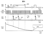
- FIG. 5 shows another reference example which is a premise of the present embodiment. That is, it is an explanatory diagram showing the relationship between the camera operation and the remaining battery power when the position detection by GPS is always performed while the battery is attached to the camera, regardless of whether the power switch of the camera is ON or OFF.
- FIG. 5 shows a camera power supply 5000 indicating ON / OFF of the power switch of the camera, a GPS position acquisition 5010 indicating ON / OFF of the GPS position acquisition operation, and a shooting indicating ON / OFF of the shooting operation, as in FIG.
- a graph of the remaining power 5030 showing the relationship between 5020 and the time of the remaining power of the battery is shown.
- FIG. 5 shows another reference example which is a premise of the present embodiment. That is, it is an explanatory diagram showing the relationship between the camera operation and the remaining battery power when the position detection by GPS is always performed while the battery is attached to the camera, regardless of whether the power switch of the camera is ON or OFF.
- FIG. 5 shows a
- ON / OFF of the power source 5000 and photographing 5020 are the same as the power source 4000 and photographing 4020 shown in FIG.
- GPS position information acquisition 5010 is always the same as ⁇ t 1 (5011), which is the same as the time ⁇ t 1 (4013) shown in FIG.
- the position information is updated in a cycle of once every few seconds.
- the initial operation of GPS does not require a long time like T 1 (4011) in FIG. 4, so it is acquired within a time range of once every few seconds at the maximum for each shooting (5021, 5022, etc.).
- the recorded position information is recorded in the captured image file. For this reason, an error in the relationship between the shooting timing and the current position is reduced.
- the remaining power 5030 of the battery used in the camera that performs these operations is not always turned off and is always operating as compared to the remaining power 4030 of FIG.
- the remaining power of the camera continues to decrease.
- the time left after shooting is long, the possibility of causing the battery down 5050 is extremely increased. Therefore, even if a camera that is normally left unattended is used suddenly, it cannot be operated, and the most basic and indispensable function of the camera can be achieved. It becomes difficult.
- FIG. 6 is an explanatory diagram showing the relationship between the camera operation of the image acquisition device having the position information detection function and the remaining battery power in this embodiment.
- FIG. 6 is similar to FIGS. 5 and 4, the camera power source 6000 indicating ON / OFF of the power switch of the camera, the GPS position acquisition 6010 indicating ON / OFF of the GPS position acquisition operation, and the ON / OFF of the shooting operation.
- a graph of the remaining power 6030 showing the relationship between the shooting 6020 indicating the time and the time of the remaining power of the battery is shown.
- ON / OFF of the camera power source 6000 and the photographing operation 6020 are the same as the camera power sources 4000 and 5000 and the photographing operations 4020 and 5020 shown in FIGS. 4 and 5.
- the GPS position acquisition 6010 continues to operate while the battery is attached to the camera regardless of whether the camera power switch is turned on or off, but depending on the timing of the camera power supply 6000 and the shooting 6020, It is characterized by switching the acquisition interval of information acquisition.
- FIG. 6 first, in a state where the camera has been left for a while (left), GPS position acquisition is not operated as in the embodiment of FIG. Therefore, in this state, the battery is not consumed as shown in FIG. 5, and the remaining power 6030 of the battery continues to be maintained without being reduced, except for natural leakage. Then, at the timing of using the camera, such as when going out with a normal camera, turn on the camera once (6001) and check the subject monitor and AF operations using the viewfinder. GPS position acquisition is performed at the timing when the power switch of this camera is turned on. In this state, basic data such as the orbit and time of the artificial satellite of this day is received.
- the current position detection is continued by providing a time interval in which basic data such as time and time may not be re-acquired.
- the state is switched to a state in which the camera is powered on for shooting purposes.
- the current position can be acquired within a range that does not require reacquisition of the satellite's orbit and time.
- the relationship between the shooting time and the current position can be accurately maintained with minimal error.
- the reacquisition is not necessary from the timing of periodic position acquisition by GPS.
- the camera is left for a longer period of time (for example, 10 hours), the camera is deemed to have been used and the GPS position acquisition is completely stopped. In this way, by dynamically changing the GPS position acquisition interval according to the camera handling status by the user, the battery residual power is minimized while keeping the relationship error between the captured image and the shooting position to a minimum. It becomes possible to do.
- triggers such as shooting, that is, the timing of pressing the shutter button or the timing of AF lock by half-pressing the shutter button.
- the relationship between the captured image and the acquired position information includes the satellite orbit by GPS and the time of day.
- An error in the time taken for acquisition occurs.
- shooting information B (2030) in FIG. 2 is provided with an area for storing an error occurrence and a numerical value of the difference between the shooting time and the position information acquisition time
- the image is displayed on a camera or a playback device.
- it is possible to confirm the presence or absence of miscalculation by superimposing the icon or numerical value indicating the occurrence of this error on the thumbnail list at the time of playback or the image displayed in full screen, or by viewing the attributes of the image file.
- the remaining power of the battery is measured by measuring the amount of power discharged from the battery as the camera consumes the battery in addition to measuring the voltage at the power supply terminal of the battery. Any other method may be used such as a value obtained by subtracting (mAh unit or the like) as the remaining power.
- the present embodiment is an image acquisition apparatus having a position information acquisition function and an image information acquisition function.
- the image acquisition apparatus is operated by a battery and is operated by operating a power switch.
- the image information storage function for storing the position information of the image acquisition device acquired by the position information acquisition function in addition to the image information acquired by the image information acquisition function.
- the position information is acquired at a first time interval from the time when the battery is mounted on the image acquisition device, and the position information acquisition function is acquired in accordance with the operation of the power switch or the image information acquisition function. Is changed from the first time interval.
- a position information acquisition method for an image acquisition apparatus having a position information acquisition function and an image information acquisition function
- the image acquisition device is operated by a battery and transitions to a state in which it operates by operating a power switch, and at a position information acquisition interval of a first time interval from the time when the battery is attached to the image acquisition device.
- Position information acquisition of the image acquisition device is performed, and the position information acquisition interval is changed from the first time interval in response to an operation of a power switch or an operation of acquiring image information.
- the coordinates of the shooting location are obtained as accurately as possible and added to the shot image, while reducing battery consumption, preventing longer camera operation and shooting impossibility due to battery consumption. I can do it.
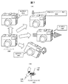
- FIG. 7 is an explanatory diagram showing the state of a camera useful as a trigger for changing the GPS position detection timing by the image acquisition device having a position information detection function in the present embodiment.
- FIG. 7A shows an example of the state of the camera.
- the camera is turned on at the time of shooting, the viewfinder is looked into, the subject is focused by AF, and the shutter is released.
- (7020) is the basic operation, but in other cases, for example, when it is not in use, the so-called neglected time elapsed (7010), or the camera operates Although there is a state where the current position frequently changes (7030) while traveling, etc., and there is a state (7040) where the posture of the camera changes due to the operation of picking up the camera that is placed .
- Lapse of time means that the camera is in a neglected state, so it is necessary to prevent the battery from being consumed by extending the GPS position detection interval or cutting it completely.
- the other items 7020, 7030, and 7040 are important information for the user to detect in advance the signs of using or actually using the camera. The electrical operation of the camera by detecting these states will be described with reference to FIGS.
- FIG. 7B is an example of a device that easily detects the posture change (7040) shown in FIG. 7A with low power consumption.
- Mercury particles 7051 are placed in a tube-shaped member, and the mercury particles 7051 move through the tube-shaped member by inclination.
- An electrode 7052 is inserted into the tube-shaped member, and the electrode is short-circuited when mercury particles 7051 are present at that location.
- a high / low switching trigger signal is generated by ON / OFF of the electrode.
- an acceleration detection method using a strain gauge, a G sensor, or the like may be used as a method for detecting the posture of the camera.
- the camera attitude change can be taken out as a signal line high / low change without consuming power. It is useful as a device that detects in advance that “uses”.
- the installation location and direction of the posture change detection SW (7050) depends on the shape of the camera, but it can be used by users in various situations, such as being placed on a shelf or sleeping in a camera bag.
- the posture change detection SW (7050) may be installed at an optimal position where the signal line changes when the camera holds the camera.
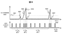
- FIG. 8 is an explanatory diagram showing the position information acquisition interval of the image acquisition apparatus having the position information detection function in the present embodiment.
- the interval for detecting the position information is changed using the power ON / OFF of the camera and the timing of shooting, whereas in the present embodiment, the current position of the camera has changed.
- the interval for detecting the position information is changed according to the distance.
- the distance between the two position information detected at the time interval is detected, that is, the position information is detected according to the relative movement distance. It is characterized by changing the time interval.
- Position information detection accuracy by GPS may cause measurement errors under various conditions, such as whether there are high buildings in the vicinity and how many artificial satellites are received at the time of measurement.
- a measurement error that is normally considered is determined to be noise, and the distance between two consecutive position information is a threshold that is equal to or greater than the maximum value of the noise. If it is within the distance (9001) set as hold, it is not determined that the camera has moved (9002), and the time interval for position acquisition is not changed.
- the position information detection time interval is continuously set after that and the position information is continuously detected.
- T ⁇ t 0 (9011) and ⁇ t 1 (9012)
- T ⁇ t 0 (9011) and ⁇ t 1 (9012)
- the time interval may be dynamically changed so that a time error does not occur in the acquired value. This method is effective, for example, when a camera operation such as taking a picture of a landscape is performed while traveling on a highway by a car or traveling by train.
- FIG. 9 is an explanatory diagram showing the position information acquisition interval of the image acquisition apparatus having the position information detection function in the present embodiment. 6 uses the camera power ON / OFF and shooting timing, and FIG. 8 changes the interval for detecting position information using the distance information of two consecutive position information measurement results.
- the change in the detection time interval of the position information is detected by detecting that the user has moved the direction of the camera for taking a picture, which is described as “camera posture change” in FIG. It is a feature.
- T ⁇ t 0 (10011)
- Position information is acquired before turning on, and an accurate current position corresponding to shooting immediately after the power is turned on can be acquired.
- FIG. 9B is a simple circuit example for collectively handling the conditions for changing the position information acquisition intervals in FIGS. 8 and 9A.
- the electrode of the posture change detection SW shown in FIG. 7B switches between short-circuiting and releasing according to the position of the mercury particles inside. By outputting the switching point of this signal as a pulse signal, it can be detected as an event that the camera has undergone some posture change in any direction.
- a signal indicating this event is an attitude change detection SW trigger 10040.
- the conditions for changing the position information acquisition interval include the power switch operation and the shutter button operation described in the explanation of FIG. 6, and these are also event signals of power ON / shutter trigger 10030.
- the event signal may be that the camera has been removed from the camera. Further, by performing a logical OR (10040) of these, it becomes possible to collectively use the position information acquisition interval as one event of the position acquisition trigger 10050.
- the event is not limited to the above.
- the switch provided near the optical viewfinder is pushed.
- the switch placed at an appropriate position on the body is pushed. Any other method may be used as long as it is a method for detecting in advance that the user is taking a picture, and when these are combined to satisfy a specific condition, “the user takes a picture.
- An operation method of “detecting what to do in advance” may be used.
- FIG. 10 is an explanatory diagram showing an example of a program for controlling a specific operation of the camera of the image acquisition apparatus having the position information detection function in the present embodiment.
- a program that actually operates on the camera a loop for counting a plurality of times is run to unconditionally reduce the power consumption of the CPU operation.
- OS an event-driven operating system
- the event-driven OS is particularly effective as an OS for devices that want to perform power-saving operations.
- This OS is not a concept in which a program operates according to a flow chart of one row, but a plurality of programs (hereinafter referred to as tasks) having various functions always exist on the memory and wait for an operation instruction.
- each function is, for example, when an event occurs when a button is pressed. Recognizes the occurrence of an event as interrupt information to the CPU, and executes a task that performs processing corresponding to the button according to the interrupt type and priority.
- TASK_INIT (11000) which is an initial value setting task, is called from the OS to set the initial value of this program to be executed when the camera is started after the power is completely turned off (with the battery removed).
- TASK_INIT (11000) has the right to use the CPU when called from the OS, and as an initialization process to be executed, the initial value of the position information acquisition time interval and the position information to be performed in the set position information acquisition time interval Set the number of acquisition processes.
- the OS calls various initial setting tasks to make each camera hardware operate normally in the same way as TASK_INIT (11000), and all initial settings are completed. By the way, it returns to the state of the standby (do nothing) task and waits for an interrupt due to the next event.
- TASK_CLOCK (11100), which is a one time / second PIN (trigger) output task, will be described.
- TASK_CLOCK 11100
- TASK_T 11300
- TASK_T 11300
- TASK_T 11300
- TASK_TRIG 11200 which is a position acquisition task
- TASK_TRIG 11200
- Fig. 9 B
- a position acquisition trigger indicating that the user has previously sensed that the camera will be used for shooting as an interrupt to the CPU, and the user takes a picture.
- TASK_GPS (11600)
- TASK_GPS (11600)
- the CPU usage right is passed to TASK_GPS (11600)
- TASK_GPS (11600) ends the CPU usage right is returned to TASK_T2 (11400), and TASK_T2 (11400) similarly returns the CPU usage right to the OS and enters a standby state.
- TASK_T (11300) which is a periodic position information acquisition task
- TASK_T (11300) has a function to call TASK_GPS (11600), which is a position acquisition task, according to a given position information acquisition time interval and the number of times.
- This process is the same as the operation according to the initial value set by TASK_INIT (11100), except for the L count.
- TASK_T2 (11400) is executed
- execute the initialization process again with TASK_INIT (10000), set the initial value of the position information acquisition time interval and the number of times the position information acquisition process is performed in the set position information acquisition time interval, and use the CPU To return to the standby state.
- TASK_GPS 11600
- This task receives GPS satellite radio waves (11601), and if radio waves can be received, the current position and orbit information of each artificial satellite necessary to calculate the current position information carried by the radio waves. , And receive the exact time handled by the GPS satellite (11603). This reception is repeated until all the information is received (11604). In particular, the initial reception takes time because it receives not only the propagation distance of the currently received radio wave but also the above-mentioned orbit information.
- the loop is repeated until the reception is completed.
- this reception part is also driven by the event-driven receiver and its output. Until the data is completely extracted from the buffer, the CPU usage right is returned to the higher-level task each time, and it is originally desirable to enter a standby state. All basic operations including camera power-on cannot be performed because all CPU resources are allocated to the 11604 loop in TASK_GPS (11600)).
- the position coordinates in the unit of the latitude and longitude of the earth are calculated using it (11605). Then, the coordinate value is passed to the caller task and the shooting / image information compression / attribute information addition task (not shown) that actually needs the information. Enters a waiting state.
- the GPS built-in portable information terminal GPS A system that manages the location information measured by the above and the unique ID of the wireless LAN router is uploaded to the cloud, and the information is managed.
- the connected device can know its current position as a rough position.
- image data can be transmitted to the device using Bluetooth.
- the captured images can be uploaded to a social network service (hereinafter referred to as SNS) or sent to an acquaintance by e-mail.
- SNS social network service
- the camera can know its current position information. In this case, even when the camera does not have a function of measuring the current position information, it can be used as a means for knowing the current position information.
Abstract
Dans certaines situations, le démarrage initial par un appareil photo numérique d'une fonction d'acquisition de position utilisant le GPS prend du temps, ce qui fait qu'il n'est pas possible pour l'appareil photo d'acquérir des informations de position exactes au moment de la capture d'image. De plus, l'utilisation constante de la fonction d'acquisition de position consomme l'énergie de la batterie et peut rendre impossible la prise d'une image. Afin de résoudre ces problèmes, la présente invention concerne un appareil d'acquisition d'images doté d'une fonction d'acquisition d'informations de position et d'une fonction d'acquisition d'informations d'image. L'appareil d'acquisition d'images est alimenté par batterie, passe à un état de fonctionnement par l'actionnement d'un interrupteur d'alimentation, et est doté d'une fonction de sauvegarde d'informations d'image par laquelle des informations de position concernant l'appareil d'acquisition d'images, acquises au moyen de la fonction d'acquisition d'informations de position, sont ajoutées à des informations d'image acquises au moyen de la fonction d'acquisition d'informations d'image, et sont sauvegardées. La fonction d'acquisition d'informations de position est configuré pour effectuer une acquisition d'informations de position à intervalles d'un premier laps de temps à partir du moment de l'installation d'une batterie dans l'appareil d'acquisition d'images, et pour modifier l'intervalle d'acquisition de la fonction d'acquisition d'informations de position par rapport au premier laps de temps d'après l'actionnement de l'interrupteur d'alimentation ou l'utilisation de la fonction d'acquisition d'informations d'image.
Priority Applications (1)
| Application Number | Priority Date | Filing Date | Title |
|---|---|---|---|
| PCT/JP2015/066537 WO2016199213A1 (fr) | 2015-06-09 | 2015-06-09 | Appareil d'acquisition d'images et procédé d'acquisition d'informations de position utilisé à cet effet |
Applications Claiming Priority (1)
| Application Number | Priority Date | Filing Date | Title |
|---|---|---|---|
| PCT/JP2015/066537 WO2016199213A1 (fr) | 2015-06-09 | 2015-06-09 | Appareil d'acquisition d'images et procédé d'acquisition d'informations de position utilisé à cet effet |
Publications (1)
| Publication Number | Publication Date |
|---|---|
| WO2016199213A1 true WO2016199213A1 (fr) | 2016-12-15 |
Family
ID=57504692
Family Applications (1)
| Application Number | Title | Priority Date | Filing Date |
|---|---|---|---|
| PCT/JP2015/066537 WO2016199213A1 (fr) | 2015-06-09 | 2015-06-09 | Appareil d'acquisition d'images et procédé d'acquisition d'informations de position utilisé à cet effet |
Country Status (1)
| Country | Link |
|---|---|
| WO (1) | WO2016199213A1 (fr) |
Citations (4)
| Publication number | Priority date | Publication date | Assignee | Title |
|---|---|---|---|---|
| JP2008257034A (ja) * | 2007-04-06 | 2008-10-23 | Nikon Corp | カメラ、測位装置およびカメラシステム |
| JP2011075343A (ja) * | 2009-09-30 | 2011-04-14 | Casio Computer Co Ltd | 自己位置取得装置、及び自己位置取得プログラム |
| JP2011135404A (ja) * | 2009-12-25 | 2011-07-07 | Casio Computer Co Ltd | 情報取得装置、位置情報記憶方法及びプログラム |
| WO2012165088A1 (fr) * | 2011-05-31 | 2012-12-06 | 富士フイルム株式会社 | Dispositif et programme de capture d'image |
-
2015
- 2015-06-09 WO PCT/JP2015/066537 patent/WO2016199213A1/fr active Application Filing
Patent Citations (4)
| Publication number | Priority date | Publication date | Assignee | Title |
|---|---|---|---|---|
| JP2008257034A (ja) * | 2007-04-06 | 2008-10-23 | Nikon Corp | カメラ、測位装置およびカメラシステム |
| JP2011075343A (ja) * | 2009-09-30 | 2011-04-14 | Casio Computer Co Ltd | 自己位置取得装置、及び自己位置取得プログラム |
| JP2011135404A (ja) * | 2009-12-25 | 2011-07-07 | Casio Computer Co Ltd | 情報取得装置、位置情報記憶方法及びプログラム |
| WO2012165088A1 (fr) * | 2011-05-31 | 2012-12-06 | 富士フイルム株式会社 | Dispositif et programme de capture d'image |
Similar Documents
| Publication | Publication Date | Title |
|---|---|---|
| US20180343759A1 (en) | External accessory to be attached to electronic apparatus and system | |
| US20100225779A1 (en) | Method and Device to extend camera battery life | |
| US9871970B2 (en) | Imaging apparatus, control method, and storage medium storing program | |
| JP2007255987A (ja) | 携帯機器及びそのプログラム | |
| US20140354832A1 (en) | Information processing apparatus, image capture system, information processing method, and recording medium | |
| JP2008167307A (ja) | デジタルカメラ | |
| JP2006339723A (ja) | 電子スチルカメラ | |
| JP6425413B2 (ja) | 撮像装置、制御方法、およびプログラム | |
| US20120245846A1 (en) | Portable equipment | |
| JP5433930B2 (ja) | カメラ、およびカメラシステム | |
| JP2009260600A (ja) | 電子カメラ | |
| WO2016199213A1 (fr) | Appareil d'acquisition d'images et procédé d'acquisition d'informations de position utilisé à cet effet | |
| JP4855953B2 (ja) | デジタルカメラ | |
| US10121350B2 (en) | Information device | |
| CN102457673A (zh) | 影像撷取方法及系统 | |
| US8823805B2 (en) | Imaging apparatus, control method thereof, and storage medium | |
| JP2016208648A (ja) | 電子機器、制御方法およびプログラム | |
| JP5482169B2 (ja) | デジタルカメラ、及びメッセージ表示方法、プログラム | |
| JP2009225178A (ja) | 撮影装置 | |
| JP2015041879A (ja) | 撮像装置、撮像システム、撮像装置の制御方法、プログラム、および、記憶媒体 | |
| JP2014120856A (ja) | 位置測定ユニット制御装置およびカメラ | |
| JP6238710B2 (ja) | 撮像装置、撮像装置の制御方法、プログラム | |
| KR102429360B1 (ko) | 1차전지 특성을 이용한 감시 카메라 | |
| CN109218596B (zh) | 动态拍照方法、装置及终端 | |
| JP6727840B2 (ja) | 撮像装置、撮像制御方法及びコンピュータプログラム |
Legal Events
| Date | Code | Title | Description |
|---|---|---|---|
| 121 | Ep: the epo has been informed by wipo that ep was designated in this application |
Ref document number: 15894898 Country of ref document: EP Kind code of ref document: A1 |
|
| NENP | Non-entry into the national phase |
Ref country code: DE |
|
| NENP | Non-entry into the national phase |
Ref country code: JP |
|
| 122 | Ep: pct application non-entry in european phase |
Ref document number: 15894898 Country of ref document: EP Kind code of ref document: A1 |