WO2016195085A1 - 通信方法及び通信機 - Google Patents
通信方法及び通信機 Download PDFInfo
- Publication number
- WO2016195085A1 WO2016195085A1 PCT/JP2016/066629 JP2016066629W WO2016195085A1 WO 2016195085 A1 WO2016195085 A1 WO 2016195085A1 JP 2016066629 W JP2016066629 W JP 2016066629W WO 2016195085 A1 WO2016195085 A1 WO 2016195085A1
- Authority
- WO
- WIPO (PCT)
- Prior art keywords
- frequency
- arrangement
- approximate
- frequency arrangement
- periodic
- Prior art date
- Legal status (The legal status is an assumption and is not a legal conclusion. Google has not performed a legal analysis and makes no representation as to the accuracy of the status listed.)
- Ceased
Links
Images






Classifications
-
- H—ELECTRICITY
- H04—ELECTRIC COMMUNICATION TECHNIQUE
- H04B—TRANSMISSION
- H04B1/00—Details of transmission systems, not covered by a single one of groups H04B3/00 - H04B13/00; Details of transmission systems not characterised by the medium used for transmission
- H04B1/02—Transmitters
- H04B1/04—Circuits
-
- H—ELECTRICITY
- H04—ELECTRIC COMMUNICATION TECHNIQUE
- H04J—MULTIPLEX COMMUNICATION
- H04J11/00—Orthogonal multiplex systems, e.g. using WALSH codes
Definitions
- the present invention relates to multi-carrier communication.
- the OFDM method using a synchronized periodic function generally has a high PAPR (Peak to average power ratio) and is likely to cause deterioration in communication quality.
- PAPR Peak to average power ratio
- the occupied bandwidth is increased and the adjacent interference is increased due to the intermodulation distortion in the transmission system.
- the present invention has been made in connection with the solution of the above problems.
- One aspect of the present invention is a communication method including communication using multicarriers, wherein the frequency arrangement of the multicarriers is asynchronous between the multicarriers and the frequency intervals are unequal. Includes an approximately periodic frequency arrangement.
- the communication is meant to include broadcasting.
- Another aspect of the present invention is a communication device that includes a modulation unit that modulates a subcarrier based on a transmission code.
- the subcarrier frequency arrangement includes an almost periodic arrangement that is asynchronous with respect to the frame time length.
- the communication method according to the embodiment is a communication method including performing communication using a multicarrier.
- the multicarrier frequency arrangement includes an almost periodic frequency arrangement in which the frequency intervals between carriers are non-uniform.
- the almost periodic frequency arrangement is a frequency arrangement that is asynchronous between any subcarriers with respect to the frame time length used as a delimiter of the signal sequence, and includes an arrangement with non-equal intervals.
- the almost periodic frequency is the frequency of each subcarrier on the almost periodic frequency arrangement.
- the frequency intervals of the subcarriers are set at equal intervals so as to satisfy the orthogonal condition so that the carriers (subcarriers) do not interfere with each other.
- OFDM OFDM
- by arranging subcarriers at equal intervals that satisfy orthogonal conditions interference between subcarriers can be prevented even if the subcarrier frequency interval is reduced so that the bands of the subcarriers overlap each other.
- the PAPR tends to be high.
- the sub-carriers are arranged in an approximately periodic frequency that is asynchronous with respect to the frame time length, it is possible to suppress an increase in PAPR even if the number of multiplexed carriers is increased.
- the approximate periodic frequency arrangement can be determined based on an approximate periodic function.
- the approximate periodic function can be based on a Weyl sequence.
- the Weyl sequence is based on Weyl's uniform distribution theorem that the fractional part of an integral multiple of an irrational number is uniformly distributed in [0, 1). In addition, the fractional part that is a multiple of the real number is also uniformly distributed in [0, 1).
- the approximate periodic frequency may be determined from an irrational number group, a rational number group that limits the number of significant digits of the irrational number, or a rational number that approximates an irrational number determined based on an approximate periodic function. It may be determined from a group.
- the approximate periodic frequency allocation is generated from a prime number using an approximate periodic function by determining a reference frequency allocation with equal frequency intervals between subcarriers. It can be determined by selecting an approximate periodic frequency close to the reference carrier frequency in the reference frequency arrangement in which the frequency interval between the subcarriers is equal from the set approximate periodic frequency group.
- the almost periodic frequency group can be generated using an almost periodic function.
- the reference frequency arrangement is preferably a frequency arrangement that satisfies the orthogonality condition and the frequency interval between the carriers is equal, as in the carrier frequency arrangement in OFDM, but the optimum reference frequency arrangement may be determined depending on the form of communication to be applied. good.
- the reference carrier frequency is each carrier frequency in the reference frequency arrangement.
- the combined substantially periodic frequency arrangement includes at least a first partial approximate periodic frequency arrangement and a second partial approximate periodic frequency arrangement other than the first partial approximate periodic frequency arrangement, and a second partial approximate period other than the first part.
- the frequency arrangement can be easily obtained by shifting the frequency of the first partial substantially periodic frequency arrangement.
- the first partial approximate periodic frequency arrangement can be determined based on an approximate periodic function.
- the second partial approximate periodic frequency allocation other than the first partial approximate periodic frequency allocation is obtained by shifting the frequency of the first partial approximate periodic frequency allocation, so that each of the first portion and the portion other than the first portion is obtained with respect to the frame time length
- the subcarriers can be made asynchronous and an almost periodic frequency arrangement can be obtained.
- a plurality of partial approximate periodic frequency arrangements may be obtained from the first partial approximate periodic frequency arrangement by frequency shift. That is, one or a plurality of partial approximate periodic frequency arrangements can be obtained by frequency shift. When obtaining a plurality of partial approximate periodic frequency arrangements, the amount of frequency shift from the first partial approximate periodic frequency arrangement may be varied.
- the frequency arrangement of multicarriers may include blank portions of subcarriers.
- the blank part of the carrier may be used, for example, as a guard interval that prevents intersubcarrier interference or as a noise measurement interval.
- the frequency arrangement of the multicarrier includes a substantially periodic frequency arrangement and may partially include a frequency arrangement that is not an approximately periodic frequency arrangement. For example, even if the frequency arrangement of the multicarrier includes a frequency arrangement in which the subcarriers are synchronized with the frame time length, the asynchrony of the substantially periodic frequency arrangement is maintained.
- the multicarrier frequency arrangement may include a pilot frequency. Further, carrier wave recovery may be performed using a pilot frequency.
- Each carrier included in the multicarrier may be subjected to N-level multiplex modulation such as QPSK or N-QAM, power level modulation, or phase modulation in order to increase transmission efficiency. May be done.
- the spectrum may be made uniform by applying a window function to the multi-carrier frame.
- the signal on the time axis of the multicarrier with the almost periodic frequency arrangement is subjected to FFT processing, then the transmission frequency is band-limited, and then IFFT processing is performed to convert the signal on the time axis. Can be sent.
- FFT processing is performed in advance on the same approximate periodic frequency arrangement as that used for transmission, and a cross-correlation value is obtained after FFT processing on the received signal of the multicarrier having the approximate periodic frequency arrangement.
- the cross-correlation value may be obtained on the time axis or may be obtained from the cross spectrum.
- PAPR may be further improved by limiting the power of multicarrier transmission with an approximately periodic frequency arrangement.
- multi-carrier signals with almost periodic frequency arrangement are frequency converted (up-converted) to the required radio frequency band, and in the receiving system, the received signals in the radio frequency band are down-converted to the base frequency band.
- a multi-carrier signal having a substantially periodic frequency arrangement may be obtained.
- the transmission power transmitted from each terminal may be controlled to make the reception level at the base station (server station) substantially constant.
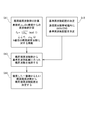
- FIG. 1 shows a procedure for determining an approximately periodic frequency arrangement
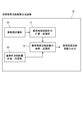
- FIG. 2 shows an approximately periodic frequency arrangement generating device (an approximately periodic frequency arrangement generating unit) 10.
- the almost periodic frequency arrangement generation device 10 is configured by, for example, a computer having a processor and a memory.
- the computer constituting the approximately periodic frequency arrangement generating apparatus 10 executes the procedure shown in FIG. 1 by executing a computer program stored in the memory, and functions as the approximately periodic frequency arrangement generating apparatus shown in FIG.
- the almost periodic frequency generation device 10 may be mounted on a communication device, or may be configured as a device different from the communication device.
- the 2 includes a prime group storage unit 11, an approximate periodic frequency group calculation / storage unit 12, a reference frequency allocation calculation / storage unit 13, and an approximate periodic frequency allocation search / And a storage unit 14.
- the prime group storage unit 11 stores a large number (for example, 10 million) of prime numbers used for calculating the approximate periodic frequency.
- the approximate cycle frequency group calculation / storage unit 13 calculates and stores the approximate cycle frequency using the prime numbers stored in the prime number group storage unit 11.
- the reference frequency arrangement calculation / storage unit 13 calculates and stores a reference frequency arrangement used to determine the approximate periodic frequency arrangement.
- the search / storage unit 14 for the approximate periodic frequency arrangement searches and selects an approximate periodic frequency close to the reference carrier frequency in the reference frequency arrangement from the approximate periodic frequency group, determines the approximate periodic frequency arrangement, and determines the determined approximate period. The frequency arrangement is stored.
- the approximate periodic frequency group is calculated by the approximate periodic frequency group calculation / storage unit 12 (step S11).
- the calculation / storage unit 12 of the approximate periodic frequency group calculates and stores the approximate periodic frequency f k according to the equation (approximately periodic function) in step S11 of FIG.
- n is an arbitrary integer or real number, but may be 1.5, 2, or 3, for example.
- (mod 1) is a function for obtaining a decimal part of a real number.
- the approximate periodic function is not limited to the format shown in FIG.
- the equation (approximately periodic function) in step S11 of FIG. 1 shows an example of obtaining from the nth root of a prime number in order to obtain an irrational approximate periodic frequency. It may be a power (e n ) or may be obtained by irrational addition and subtraction.
- e n a power
- irrational addition and subtraction In order to obtain the approximate periodic frequency of rational numbers, there are methods such as limiting the number of digits of the irrational approximate periodic frequency and obtaining it as an integer fraction.
- the horizontal axis indicates the size of the prime number
- the vertical axis indicates the normalized frequency.
- 3A and 3B show points where black portions are plotted. From the prime numbers, it can be seen that a large number of frequencies are uniformly distributed over the entire range (0 to 1) of the normalized frequency. .
- the reference frequency arrangement is calculated by the reference frequency arrangement calculation / storage unit 13.
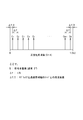
- FIG. 4 shows an example of the reference frequency arrangement.
- the frequency interval ⁇ f between carriers is equal.
- the total number N of reference carriers is also the number of code multiplexes, and is preferably a power of 2 in order to reduce the calculation load.
- C 1 to C N indicate N reference carriers.
- ⁇ f / 2 is the frequency between the reference carriers (subchannels) C 1 and C N on both sides of the normalized frequency range and the edge of the pass bandwidth (normalized frequency is 0 or 1). Showing the difference.
- the frame time length of the approximate periodic function may be processed in units of N ⁇ T according to the number of multiplexing N.
- the signal processing time length T N ⁇ T.
- 1 / N ⁇ T is a fundamental frequency
- ⁇ f 1 / (N ⁇ T)
- step S13 the search / storage unit 14 for the approximate periodic frequency arrangement searches the approximate periodic frequency used for the approximate periodic frequency arrangement from the approximate periodic frequency group obtained in step S12.
- step S14 N approximate periodic frequencies closest to the frequencies of the target reference carriers C 1 to C N are extracted from the retrieved approximate periodic frequencies, and are composed of the extracted N approximate periodic frequencies. An approximately periodic frequency arrangement is determined.
- the approximate periodic frequency obtained from the approximate periodic function shown in FIG. 1 is an irrational number, it does not match the frequencies of the reference carriers C 1 to C N that are rational numbers. For this reason, the searched approximate periodic frequency arrangement composed of N approximate periodic frequencies is non-uniformly spaced. However, since frequencies close to the reference carriers C 1 to C N that are equally spaced are selected, they are generally equally spaced. Incidentally, almost periodic frequency, if it is rational does not coincide with the frequency of the reference carrier C 1 ⁇ C N, it may be selected close to the frequency of the reference carrier C 1 ⁇ C N.
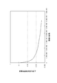
- Figure 5 is almost periodic frequency selected, the reference carrier C 1 ⁇ C N normalized frequency standard deviation of how close the normalized frequency of the reference carrier C 1 ⁇ C N to a frequency of (standard deviation) Show.
- the horizontal axis represents the total number of prime numbers used in step S11
- the vertical axis represents the normalized frequency standard deviation.
- the larger the total number of primes the easier it is to select frequencies close to the reference carriers C 1 to C N and the smaller the frequency standard deviation.
- the total number of prime numbers exceeds 1 million, the frequency standard deviation becomes about 0.001 or less, and the interference between subcarriers can be reduced while maintaining the asynchrony of the approximate periodic frequency arrangement.
- the standard deviation approaches zero and approaches the OFDM method.
- FIG. 6 shows a communication device 20 that performs communication using multicarriers having a substantially periodic frequency arrangement.
- the communication device 20 includes a multi-carrier signal transmitter 30 and a multi-carrier signal receiver 40.
- the transmitter 30 includes an input unit 31, a serial / parallel conversion unit 32, a subcarrier modulation unit 33, a multicarrier generation unit 34 having a substantially periodic frequency arrangement, an output unit 35, and a synchronization signal generation unit 36. ing.
- the input unit 32 receives an input of a transmission code (transmission data) from a signal processing device (not shown) included in the communication device 20, and performs preprocessing that should be performed prior to multicarrier modulation if necessary.
- the serial / parallel converter 32 converts the serial code (serial data) output from the input unit 32 into a parallel code (parallel data) having a parallel number corresponding to the multiple code length N.
- a parallel code having a code length N is a transmission code.
- the subcarrier modulation unit 33 performs almost periodic frequency division multiplexing shown in FIG.
- the subcarrier modulation unit 33 performs subcarrier modulation of a transmission code (d 1 d 2 d 3 ... D N ⁇ 1 d N ) having a code length N, and generates a code string (y 1 y 2 y 3. y N-1 y N ) is output as a multi-carrier signal having a substantially periodic frequency arrangement.
- the subcarrier modulation unit 33 performs multicarrier modulation based on the multicarrier given from the multicarrier generation unit 34 having a substantially periodic frequency arrangement.
- the multi-carrier generating unit 34 having the substantially periodic frequency arrangement may include the approximate frequency arrangement generating unit 10 illustrated in FIG. 2, or the approximate periodic frequency determined by the approximate frequency arrangement generating unit 10 illustrated in FIG. 2. An arrangement may be set, and a carrier having the set approximate periodic frequency arrangement may be generated.
- a matrix having elements a k b k to p k (1 ⁇ k ⁇ N) is an N ⁇ N matrix.
- ⁇ dk is a prime number used to generate the k th frequency in an approximately periodic frequency arrangement having N carriers.
- ⁇ k is an arbitrary real number and may be 0.
- C k to P k are amplitude values of the k-th carrier similarly to A k and B k .
- the subcarrier signal output from the subcarrier modulation unit 33 is supplied to the output unit 35, and the output unit 35 transmits a transmission path (such as a radio propagation path) as an approximately periodic subcarrier output signal (an approximately periodic frequency subcarrier composite signal). Is output.
- a transmission path such as a radio propagation path
- an approximately periodic subcarrier output signal an approximately periodic frequency subcarrier composite signal
- the serial / parallel conversion unit 33, the subcarrier modulation unit 33, and the output unit 35 operate based on the synchronization signal provided from the synchronization signal generation unit 36.
- the receiver 40 includes an input unit 41, a subcarrier demodulation unit 42, a frequency generation unit 43 having a substantially periodic frequency arrangement, a parallel / serial conversion unit 44, an output unit 45, and a synchronization signal generation unit 46. Yes.
- the input unit 41 receives an input of a reception signal (substantially periodic frequency subcarrier composite signal) and gives the reception signal to the subcarrier demodulation unit 42.
- the subcarrier demodulator 42 obtains the cross-correlation value (complex correlation value) between the approximate periodic frequency (delayed approximate periodic frequency arrangement; approximate periodic complex carrier) used on the transmission side of the received signal and the received signal. Demodulate.
- the frequency of the demodulated substantially periodic frequency arrangement is given from the frequency generating unit 43 of the almost periodic frequency arrangement.
- the cross-correlation value of signals for example, the following “method for obtaining on the time axis” and “method for obtaining from cross spectrum” can be employed.
- the signal output from the demodulator 42 is converted into serial data by the parallel-serial converter 44.
- This serial data is output as a demodulated code to a signal processing device (not shown) via the output unit 45.
- the input unit 41, the subcarrier demodulation unit 42, the frequency generation unit 43 with a substantially periodic frequency arrangement, and the parallel-serial conversion unit 44 operate based on the synchronization signal provided from the synchronization signal generation unit 46.
- FIG. 8A shows an output unit 35 having a band limiting function.
- the output unit 35 includes an input processing circuit 351 that receives an input of an approximately periodic frequency subcarrier composite signal (time domain signal) given from the modulation unit 33, an FFT processing circuit 352, a band limitation processing circuit 353, and an IFFT process.
- a circuit 354 The FFT processing circuit 352 converts the substantially periodic frequency subcarrier composite signal, which is a time domain signal, into a frequency domain signal.
- the band limitation processing circuit 353 limits the frequency band of the signal and removes unnecessary frequency components.
- the IFFT processing circuit 354 returns the band-limited signal to the time axis domain signal. Since the output unit 35 has the configuration shown in FIG. 8A, it is possible to limit the band for the substantially periodic frequency subcarrier composite signal.
- FIG. 8B shows an input unit 41 having a band limiting function.
- the input unit 41 includes an input processing circuit 411 that receives an input of a substantially periodic frequency subcarrier composite signal (time domain signal) that is a received signal, an FFT processing circuit 412, a band limiting processing circuit 413, and an IFFT processing circuit 414. It is equipped with.
- the FFT processing circuit 412 converts the substantially periodic frequency subcarrier synthesized signal, which is a time domain signal, into a frequency domain signal.
- the band limitation processing circuit 413 limits the signal band and removes unnecessary frequency components.
- the IFFT processing circuit 414 returns the band-limited signal to the time axis domain signal.
- the band-limited signal is supplied to the subcarrier demodulation unit 42.
- FIG. 9 has a multi-access communication system having a large number of terminals and base stations.
- the above-described communication device 10 may be the base station of FIG. 9 or a terminal.
- the transmission power of the substantially periodic multicarrier signal transmitted from each terminal is controlled by the terminal based on an instruction from the base station, and the reception level at the base station may be substantially constant.
- FIG. 10 shows the PAPR simulation values of the OFDM signal and the substantially periodic frequency allocation subcarrier composite signal.
- the horizontal axis indicates the number of multiplexed subcarriers
- the vertical axis indicates PAPR.
- the PAPR of the substantially periodic frequency-arranged multicarrier signal tends to be lower than the PAPR of the OFDM signal and exhibit good characteristics.
- the PAPR tends to decrease because of the effect that the error order of the Weyl sequence becomes O (1 / ⁇ N).
- FIG. 11 illustrates a modification of the receiver 30 included in the communication device 20. 11 is obtained by adding a PAPR compensation unit 37 to the receiver 30 shown in FIG.
- the PAPR compensation unit 37 is provided between the subcarrier modulation unit 33 and the output unit 35.
- the PAPR compensation unit limits the peak value of the norm of the vector on the time axis of the almost periodic frequency subcarrier composite signal to improve the PAPR of the almost periodic frequency subcarrier composite signal.
- the substantially periodic frequency subcarrier composite signal with improved PAPR is output to a transmission path (such as a radio propagation path) via the output unit 35.
- FIG. 12 shows a circuit configuration example of the PAPR compensation unit 37.
- the PAPR compensation unit 37 includes an input unit 37a, a peak value detection unit 37b, an impulse new signal generation unit 37c, a complex synthesis unit 37d, and an output unit 37e.
- the input unit 37a accepts an input of an approximately periodic frequency subcarrier composite signal.
- the peak value detection unit 37b detects the position and peak value of the peak of the substantially periodic frequency subcarrier composite signal output from the input unit 37a on the time axis.
- the complex synthesizer 37d When the detected peak value exceeds the specified value, the complex synthesizer 37d generates a peak for the signal generated by the impulse signal generator 37c with respect to the substantially periodic frequency subcarrier synthesized signal output from the input unit 37a. Complex synthesis with opposite polarity to the value. Thereby, a peak is suppressed and PAPR reduces.
- the substantially periodic frequency subcarrier composite signal whose peak is suppressed is output via the output unit 37e.
- the signal generated by the impulse signal generator 37c is a reverse impulse signal corresponding to the difference between the detected peak value and the specified value.
- the PAPR compensation unit 37 shown in FIG. 12 can further improve the PAPR by repeating a plurality of PAPR compensation processes.
- FIG. 13 shows the result of limiting the peak by the PAPR compensation unit 37 of FIG.
- FIG. 13 shows the case where the magnitude of the inverse impulse signal (peak limit level) is set to 2 ⁇ , 1.8 ⁇ , and 1.6 ⁇ , where ⁇ is the standard deviation of the peak in the substantially periodic frequency subcarrier composite signal.
- PAPR and PAPR without PAPR compensation are shown.
- the PAPR is about 8 to 9 [dB], but when PAPR compensation is performed, the PAPR can be reduced. Further, the PAPR can be reduced as the peak limit level is deepened.
- FIG. 13 shows the frequency standard deviation of each subcarrier constituting the substantially periodic frequency subcarrier composite signal, and when the frequency standard deviation is zero, it becomes OFDM.
- the PAPR is usually about 10 dB.
- the almost periodic frequency subcarrier signal can reduce the PAPR more than the OFDM even without the PAPR compensation, and the PAPR can be further reduced by performing the PAPR compensation.
- the present embodiment it is possible to improve the frequency utilization efficiency by reducing the PAPR and reducing the intermodulation product in the transmission system by using the relationship of making the subcarrier complex frequencies asynchronous. Further, according to the present embodiment, it is possible to realize a super-multiplexing and super-multi-access communication system that can increase transmission capacity by increasing transmission power efficiency.
- the technology disclosed in the present embodiment can be applied to a wide range of communication systems (including broadcast systems) from sound / radio wave utilization systems to optical communications.
Landscapes
- Engineering & Computer Science (AREA)
- Computer Networks & Wireless Communication (AREA)
- Signal Processing (AREA)
- Transmitters (AREA)
- Mobile Radio Communication Systems (AREA)
Abstract
伝送周波数帯域幅を制限しつつPAPRの抑制を容易にする。通信方法は、マルチキャリアを用いて通信を行うことを含み、マルチキャリアの周波数配置は、フレーム時間長に対して各々のサブキャリアが非同期とする概周期周波数配置を含む。
Description
本発明は、マルチキャリア通信に関するものである。
地上デジタル放送の本格的運用と共に、超高精細な映像技術(4K・8K)を用いたより高度な放送サービスの提供が要求されてきている。地上移動通信においては、周波数利用効率が高く、高速・大容量通信、多数接続等が可能となる第5世代移動通信システムの国際標準化に向けた研究開発が進められている。地上デジタル放送および4GLTE方式では、占有周波数帯域の狭帯域化および周波数選択性干渉に対する耐干渉特性を有するOFDM方式採用されている。
梅野健、"概周期関数に基づくスペクトル拡散通信について-概周期とカオスとの違いについて-"、信学技報、vol.114,no.250 NLP2014-64, pp.87-90(2014),一般社団法人電子情報通信学会
同期した周期関数を用いたOFDM方式では、一般的にPAPR(Peak to average power ratio)が高く、通信品質の劣化を招き易い。また、送信系での相互変調歪みから占有帯域幅の拡大と隣接干渉が増加する欠点もあり、周波数有効利用からも課題が残っている。
本発明は、上記の課題の解決に関連してなされたものである。
本発明の一の態様は、通信方法であって、マルチキャリアを用いて通信を行うことを含み、前記マルチキャリアの周波数配置は、マルチキャリア間が非同期であり、周波数間隔が非等間隔である概周期周波数配置を含む。なお、ここでは、通信は、放送を含む意である。本発明の他の態様は、通信機であって、送信符号に基づいてサブキャリアを変調する変調部を備える。サブキャリアの周波数配置は、フレーム時間長に対して非同期となる概周期配置を含む。
以下、本発明の好ましい実施形態について添付図面を参照しながら説明する。
[1.実施形態の概要]
実施形態に係る通信方法は、マルチキャリアを用いて通信を行うことを含む通信方法である。マルチキャリアの周波数配置は、キャリア間の周波数間隔が非等間隔である概周期周波数配置を含む。実施形態において概周期周波数配置とは、信号列の区切りとするフレーム時間長に対して何れのサブキャリア間においても非同期である周波数配置であり、非等間隔な配置を含む。また、概周期周波数(Almost Periodic Frequnecy)とは、概周期周波数配置上の各々のサブキャリアの周波数をいう。
実施形態に係る通信方法は、マルチキャリアを用いて通信を行うことを含む通信方法である。マルチキャリアの周波数配置は、キャリア間の周波数間隔が非等間隔である概周期周波数配置を含む。実施形態において概周期周波数配置とは、信号列の区切りとするフレーム時間長に対して何れのサブキャリア間においても非同期である周波数配置であり、非等間隔な配置を含む。また、概周期周波数(Almost Periodic Frequnecy)とは、概周期周波数配置上の各々のサブキャリアの周波数をいう。
ここで、従来のOFDMでは、キャリア(サブキャリア)を互いに干渉させないように、サブキャリアの周波数間隔は、直交条件を満たすように等間隔で設定される。OFDMでは、直交条件を満たす等間隔のサブキャリア配置とすることで、各サブキャリアの帯域が重複するようにサブキャリアの周波数間隔を小さくしても、サブキャリア同士の干渉を防止できる。ただし、OFDMでは、サブキャリアが周期的に等間隔で配置されているため、PAPRが高くなりやすい。これに対して、本実施形態では、フレーム時間長に対して各々のサブキャリアが非同期となる概周期周波数配置であるため、キャリア多重数が多くなっても、PAPRが高くなるのを抑制できる。
概周期周波数配置は、概周期関数に基づいて決定することができる。概周期関数は、Weyl系列に基づくものすることができる。Weyl系列は、無理数の整数倍の小数部分は[0,1)に一様分布するというWeylの一様分布定理に基づいている。また、拡張して実数倍の小数部分も[0,1)に一様分布する。概周期周波数は、無理数群から決定されてもよいし、無理数の有効桁数を制限した有理数群から決定されてもよいし、概周期関数に基づいて決定される無理数に近似する有理数群から決定されてもよい。
概周期周波数配置は、サブキャリア間の周波数間隔が等間隔に近い配置にする場合には、サブキャリアの周波数間隔が等間隔である基準周波数配置を決めて、概周期関数を用いた素数から生成された概周期周波数群から、サブキャリア間の周波数間隔が等間隔である基準周波数配置における基準キャリア周波数に近い概周期周波数を選択することによって決定することができる。概周期周波数群は、概周期関数を用いて生成できる。基準周波数配置は、OFDMにおけるキャリア周波数配置のように、直交条件を満たし、キャリア間の周波数間隔が等間隔である周波数配置が好ましいが、適用する通信の形態によって最適な基準周波数配置を決めても良い。基準キャリア周波数は、基準周波数配置における各キャリア周波数である。基準キャリア周波数に近い概周期周波数を決定した場合には、キャリアを密に配置でき、キャリア間の干渉も抑えることができる。
複合した概周期周波数配置は、少なくとも、第1部分概周期周波数配置と、第1部分概周期周波数配置以外の第2部分概周期周波数配置と、を含み、第1部分以外の第2部分概周期周波数配置は、第1部分概周期周波数配置を周波数シフトして容易に得られる。第1部分概周期周波数配置は、概周期関数に基づき決定することができる。第1部分概周期周波数配置以外の第2部分概周期周波数配置は、第1部分概周期周波数配置を周波数シフトして得ることで、フレーム時間長に対して第1部分と第1部分以外の各々のサブキャリアが非同期とすることが出来て、概周期周波数配置を得る事ができる。なお、周波数シフトによって、第1部分概周期周波数配置から、複数の部分概周期周波数配置を得ても良い。すなわち、周波数シフトによって、1又は複数の部分概周期周波数配置を得ることができる。複数の部分概周期周波数配置を得る場合、第1部分概周期周波数配置からの周波数シフト量をそれぞれ異ならせればよい。
マルチキャリアの周波数配置は、サブキャリアの空白部分を含んでいても良い。キャリアの空白部分は、例えば、サブキャリア間干渉を防止するガード区間として用いても良いし、ノイズ測定用区間として用いても良い。
マルチキャリアの周波数配置は、概周期周波数配置を含むとともに、概周期周波数配置ではない周波数配置も部分的に含んでも良い。例えば、マルチキャリアの周波数配置は、フレーム時間長に対してサブキャリアが同期となる周波数配置を含んでいても、概周期周波数配置の非同期は維持される。マルチキャリアの周波数配置は、パイロット周波数を含んでも良い。また、パイロット周波数を用いて搬送波再生を行っても良い。
マルチキャリアに含まれる各キャリアには、伝送効率を上げるためにQPSK、N-QAMなどのN値多重変調が行われていても良いし、パワーレベル変調が行われていても良いし、位相変調が行われていても良い。マルチキャリアのフレームに窓関数をかけてスペクトラムを一様化してもよい。
マルチキャリア通信の送信系では、概周期周波数配置のマルチキャリアの時間軸上の信号を、FFT処理した後、送信周波数を帯域制限し、その後、IFFT処理して時間軸上の信号に変換して送信することができる。
マルチキャリア通信の受信系では、送信に用いられた概周期周波数配置と同じ概周期周波数配置を予めFFT処理しておき、概周期周波数配置のマルチキャリアの受信信号のFFT処理後に相互相関値を求めて、送信された概周期周波数の変調された符号を検出することができる。相互相関値は、時間軸上で求めてもよいし、クロススペクトラムから求めても良い。
マルチキャリア通信の送信系では、概周期周波数配置のマルチキャリア送信の電力に制限を加えて、PAPRをより改善してもよい。
マルチキャリア通信の送信系では、概周期周波数配置のマルチキャリア信号を、必要な無線周波数バンドに周波数コンバート(アップコンバート)し、受信系では、無線周波数バンドの受信信号をダウンコンバートして基底周波数帯の概周期周波数配置のマルチキャリア信号を得ても良い。
概周期周波数配置のマルチキャリアを用いたマルチアクセス通信システムにおいて、個々の端末から送信される送信電力を制御し、基地局(サーバ局)での受信レベルを略一定にしてもよい。
[2.実施形態の詳細]
[2.1 概周期周波数の決定]
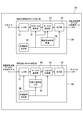
図1は、概周期周波数配置の決定のための手順を示し、図2は、概周期周波数配置生成装置(概周期周波数配置生成部)10を示している。概周期周波数配置生成装置10は、例えば、プロセッサ及びメモリを有するコンピュータによって構成される。概周期周波数配置生成装置10を構成するコンピュータは、メモリに記憶されたコンピュータプログラムを実行することにより、図1に示す手順を実行し、図2に示す概周期周波数配置生成装置として機能する。概周期周波数発生装置10は、通信機に搭載されていてもよいし、通信機とは別の装置として構成されてもよい。
[2.1 概周期周波数の決定]
図1は、概周期周波数配置の決定のための手順を示し、図2は、概周期周波数配置生成装置(概周期周波数配置生成部)10を示している。概周期周波数配置生成装置10は、例えば、プロセッサ及びメモリを有するコンピュータによって構成される。概周期周波数配置生成装置10を構成するコンピュータは、メモリに記憶されたコンピュータプログラムを実行することにより、図1に示す手順を実行し、図2に示す概周期周波数配置生成装置として機能する。概周期周波数発生装置10は、通信機に搭載されていてもよいし、通信機とは別の装置として構成されてもよい。
図2に示す概周期周波数配置生成装置10は、素数群記憶部11と、概周期周波数群の計算・記憶部12と、基準周波数配置の計算・記憶部13と、概周期周波数配置の検索・記憶部14と、を備えている。素数群記憶部11は、概周期周波数を計算するために用いられる多数(例えば、1000万個)の素数を記憶する。概周期周波数群計算・記憶部13は、素数群記憶部11に記憶された素数を用いて、概周期周波数を計算し、記憶する。基準周波数配置の計算・記憶部13は、概周期周波数配置を決定するために用いられる基準周波数配置を計算し、記憶する。概周期周波数配置の検索・記憶部14は、概周期周波数群から、基準周波数配置における基準キャリア周波数に近い概周期周波数を検索して選択し、概周期周波数配置を決定し、決定された概周期周波数配置を記憶する。
図1に戻り、概周期周波数の決定には、まず、概周期周波数群の計算・記憶部12によって、概周期周波数群の計算が行われる(ステップS11)。概周期周波数群の計算・記憶部12は、図1のステップS11中の式(概周期関数)に従って、概周期周波数fkを計算し、記憶する。ステップS11中の式において、nは任意の整数又は実数であるが、例えば、1.5,2又は3とすることができる。また、(mod 1)は、実数の小数部分を求める関数である。
なお、概周期関数は、図1に示す形式に限定されるものではない。例えば、図1のステップS11中の式(概周期関数)は、無理数の概周期周波数を求めるために、素数のn乗根から求める例を示しているが、無理数周波数は、eのn乗(en)であってもよいし、無理数の加減剰余算によって求めても良い。有理数の概周期周波数を求めるには、無理数の概周期周波数の桁数制限や、整数の分数として求めるなどの方法がある。
素数は、無限に存在するため、概周期関数は無限に生成できる。図3(a)は、図1に示す概周期関数においてn=2である場合に得られる正規化周波数(0[Hz]から1[Hz]の範囲の周波数)をプロットしたものであり、図3(b)は、同じくn=1.5である場合に得られる正規化周波数をプロットしたものである。図3において、横軸は素数の大きさを示し、縦軸は正規化周波数を示す。図3(a)(b)において黒い部分がプロットされた点を示しており、素数から、正規化周波数の全範囲(0から1)にわたって多数の周波数が一様に分布していることがわかる。
また、ステップ12において、基準周波数配置の計算・記憶部13により、基準周波数配置が計算される。図4は、基準周波数配置の例を示している。基準周波数配置は、OFDMと同様に、キャリア間の周波数間隔Δfが等間隔である。正規化周波数(0~1)の範囲で基準となる複数のキャリア(複数の基準キャリア)を配置する場合、キャリア間の周波数間隔Δfは、基準キャリアの総数Nによって決定される。すなわち、周波数間隔Δf=1/Nである。基準キャリアの総数Nは、符号多重数でもあり、2の冪であるのが計算負荷の低減上好ましい。図4において、C1~CNは、N本の基準キャリアを示している。また、図1において、Δf/2は、正規化周波数の範囲の両側にある基準キャリア(サブチャネル)C1,CNと、通過帯域幅のエッジ(正規化周波数が0又は1)との周波数差を示している。
ここで、符号当たりの時間長をΔTとすれば、多重化数Nに応じて概周期関数のフレーム時間長はNΔTを単位として信号処理をすればよい。信号処理する時間長T=NΔTである。また、1/NΔTが基本周波数となり、Δf=1/(NΔT)であり、通過帯域幅BWは、ΔfのN倍から、BW=1/ΔT[Hz]となる。
ステップS13において、概周期周波数配置の検索・記憶部14は、ステップS12において得られた概周期周波数群から概周期周波数配置に用いられる概周期周波数が検索される。ステップS14では、検索された概周期周波数のうち、ターゲットとなる基準キャリアC1~CNそれぞれの周波数に最も近いN個の概周期周波数が抽出され、抽出されたN個の概周期周波数からなる概周期周波数配置が決定される。
図1に示す概周期関数から得られる概周期周波数は、無理数となるため、有理数である基準キャリアC1~CNの周波数とは一致しない。このため、検索されたN個の概周期周波数からなる概周期周波数配置は、非等間隔となる。ただし、等間隔である基準キャリアC1~CNに近い周波数が選択されるため、概ね等間隔となる。なお、概周期周波数が、有理数である場合には、基準キャリアC1~CNの周波数とは一致しないが、基準キャリアC1~CNの周波数に近いものを選択すればよい。
図5は、選択された概周期周波数が、基準キャリアC1~CNの正規化周波数にどの程度近いかを基準キャリアC1~CNの正規化周波数からの周波数標準偏差(standard deviation)で示している。図5において、横軸は、ステップS11において用いられた素数の総数であり、縦軸は正規化周波数標準偏差を示している。図13に示すように、素数の総数が大きいほど、基準キャリアC1~CNに近い周波数を選択しやすくなり、周波数標準偏差が小さくなる。例えば、素数の総数が、100万を超えると、周波数標準偏差は、0.001程度ないしそれ以下となり、概周期周波数配置の非同期は維持されたままでサブキャリア間の干渉を減らす事ができる。図5に示すように、素数の総数が増加すると標準偏差はゼロに近づき、OFDM方式に近づくとこととなる。
[2.2 通信機]
図6は、概周期周波数配置のマルチキャリアによって通信を行う通信機20を示している。通信機20は、マルチキャリア信号の送信機30と、マルチキャリア信号の受信機40と、を備えている。
図6は、概周期周波数配置のマルチキャリアによって通信を行う通信機20を示している。通信機20は、マルチキャリア信号の送信機30と、マルチキャリア信号の受信機40と、を備えている。
送信機30は、入力部31と、シリアルパラレル変換部32と、サブキャリア変調部33と、概周期周波数配置のマルチキャリア発生部34と、出力部35と、同期信号発生部36と、を備えている。
入力部32は、通信機20が有する図示しない信号処理装置から、送信符号(送信データ)の入力を受け付け、必要であればマルチキャリア変調に先立って行われるべき前処理を行う。シリアルパラレル変換部32は、入力部32から出力されたシリアル符号(シリアルデータ)を、多重符号長Nに対応したパラレル数を持つパラレル符号(パラレルデータ)に変換する。符号長Nのパラレル符号が、送信符号となる。
サブキャリア変調部33は、図7に示す概周期周波数多重変調を行う。サブキャリア変調部33は、符号長Nの送信符号(d1d2d3・・・dN-1dN)のサブキャリア変調を行って、符号列(y1y2y3・・・yN-1yN)で示される概周期周波数配置マルチキャリア信号を出力する。サブキャリア変調部33は、概周期周波数配置のマルチキャリア発生部34から与えられたマルチキャリアに基づき、マルチキャリア変調を行う。概周期周波数配置のマルチキャリア発生部34は、図2に示す概周波数配置生成部10を備えて構成されていてもよいし、図2に示す概周波数配置生成部10によって決定された概周期周波数配置が設定されており、設定された概周期周波数配置のキャリアを発生するものであってもよい。
図7に示す入出力関係式において、要素akbk~pk(1≦k≦N)を有する行列は、N×N行列である。また、図7において、ρdkは、N個のキャリアを有する概周期周波数配置において、k番目の周波数を生成するために用いられた素数である。また、図7において、θkは、任意の実数であり、0であってもよい。
なお、図7に示す入出力関係式において、要素akbk以外の要素ck~pkの定義を明示していないが、要素akbkの定義に含まれるAk,Bkを、Ck~Pkに置換すればよい。Ck~Pkは、Ak,Bkと同様にk番目のキャリアの振幅値である。
サブキャリア変調部33から出力されたサブキャリア信号は、出力部35に与えられ、出力部35から、概周期サブキャリア出力信号(概周期周波数サブキャリア合成信号)として伝送路(無線伝播路など)へ出力される。
なお、シリアルパラレル変換部33、サブキャリア変調部33、及び出力部35は、同期信号発生部36から与えられる同期信号に基づいて動作する。
受信機40は、入力部41と、サブキャリア復調部42と、概周期周波数配置の周波数発生部43と、パラレルシリアル変換部44と、出力部45と、同期信号発生部46と、を備えている。
入力部41は、受信信号(概周期周波数サブキャリア合成信号)の入力を受け付け、受信信号をサブキャリア復調部42に与える。サブキャリア復調部42は、受信信号の送信側で用いられた概周期周波数(復調用概周期周波数配置;概周期複素搬送波)と、受信信号との相互相関値(複素相関値)を求めることで復調を行う。復調用概周期周波数配置の周波数は、概周期周波数配置の周波数発生部43から与えられる。信号の相互相関値は、例えば、以下の「時間軸上で求める方法」「クロススペクトラムから求める方法」を採用できる。

復調部42からから出力された信号は、パラレルシリアル変換部44によってシリアルデータに変換される。このシリアルデータは、出力部45を介して、図示しない信号処理装置へ、復調された符号として、出力される。
なお、入力部41、サブキャリア復調部42、概周期周波数配置の周波数発生部43、パラレルシリアル変換部44は、同期信号発生部46から与えられる同期信号に基づいて動作する。
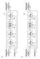
図8(a)は、帯域制限機能を有する出力部35を示している。この出力部35は、変調部33から与えられた概周期周波数サブキャリア合成信号(時間領域信号)の入力を受け付ける入力処理回路351と、FFT処理回路352と、帯域制限処理回路353と、IFFT処理回路354と、を備えている。FFT処理回路352は、時間領域信号である概周期周波数サブキャリア合成信号を周波数領域信号に変換する。帯域制限処理回路353は、信号の周波数帯域を制限し、不要な周波数成分を除去する。IFFT処理回路354は、帯域制限された信号を時間軸領域信号に戻す。出力部35が、図8(a)に示される構成を有することで、概周期周波数サブキャリア合成信号に対する帯域制限が可能である。
図8(b)は、帯域制限機能を有する入力部41を示している。この入力部41は、受信信号である概周期周波数サブキャリア合成信号(時間領域信号)の入力を受け付ける入力処理回路411と、FFT処理回路412と、帯域制限処理回路413と、IFFT処理回路414と、を備えている。FFT処理回路412は、時間領域信号である概周期周波数サブキャリア合成信号を周波数領域信号に変換する。帯域制限処理回路413は、信号の帯域を制限し、不要な周波数成分を除去する。IFFT処理回路414は、帯域制限された信号を時間軸領域信号に戻す。帯域制限された信号が、サブキャリア復調部42に与えられる。
図9は、多数の端末と基地局とを有するマルチアクセス通信システムを有している。前述の通信機10は、図9の基地局であってもよいし、端末であってもよい。個々の端末から送信される概周期マルチキャリア信号の送信電力は、基地局からの指示に基づいて、端末によって制御され、基地局での受信レベルがほぼ一定としても良い。
[2.3 PAPR]
図10は、OFDM方式の信号及び概周期周波数配置サブキャリア合成信号それぞれのPAPRのシミュレーション値を示している。図10において、横軸は、サブキャリア多重数を示し、縦軸はPAPRを示す。図10に示すように、サブキャリア多重化数が512を超えると、概周期周波数配置マルチキャリア信号のPAPRは、OFDM信号のPAPRよりも低下し良好な特性を示す傾向があることがわかる。また、多重化数が1000以上ではPAPRが減少の傾向にあるのはWeyl系列の誤差オーダがO(1/√N)となる効果と考えられる。
図10は、OFDM方式の信号及び概周期周波数配置サブキャリア合成信号それぞれのPAPRのシミュレーション値を示している。図10において、横軸は、サブキャリア多重数を示し、縦軸はPAPRを示す。図10に示すように、サブキャリア多重化数が512を超えると、概周期周波数配置マルチキャリア信号のPAPRは、OFDM信号のPAPRよりも低下し良好な特性を示す傾向があることがわかる。また、多重化数が1000以上ではPAPRが減少の傾向にあるのはWeyl系列の誤差オーダがO(1/√N)となる効果と考えられる。
[2.4 PAPR補償]
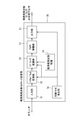
図11は、通信機20が有する受信機30の変形例を示している。図11の受信機30は、図6に示す受信機30にPAPR補償部37を追加したものである。PAPR補償部37は、例えば、サブキャリア変調部33と出力部35との間に設けられる。PAPR補償部は、概周期周波数サブキャリア合成信号の時間軸上のベクトルのノルムのピーク値に制限を加えて、概周期周波数サブキャリア合成信号のPAPRを改善する。PAPRが改善された概周期周波数サブキャリア合成信号は、出力部35を介して、伝送路(無線伝播路など)へ出力される。
図11は、通信機20が有する受信機30の変形例を示している。図11の受信機30は、図6に示す受信機30にPAPR補償部37を追加したものである。PAPR補償部37は、例えば、サブキャリア変調部33と出力部35との間に設けられる。PAPR補償部は、概周期周波数サブキャリア合成信号の時間軸上のベクトルのノルムのピーク値に制限を加えて、概周期周波数サブキャリア合成信号のPAPRを改善する。PAPRが改善された概周期周波数サブキャリア合成信号は、出力部35を介して、伝送路(無線伝播路など)へ出力される。
図12は、PAPR補償部37の回路構成例を示している。PAPR補償部37は、入力部37a、ピーク値検出部37b、インパルス新号発生部37c、複素合成部37d、及び出力部37eを備えている。
入力部37aは、概周期周波数サブキャリア合成信号の入力を受け付ける。ピーク値検出部37bは、入力部37aから出力された概周期周波数サブキャリア合成信号のピークの時間軸上における位置とピーク値とを検出する。検出されたピーク値が、規定値を超えたときには、複素合成部37dは、インパルス信号発生部37cによって発生した信号を、入力部37aから出力された概周期周波数サブキャリア合成信号に対して、ピーク値とは逆極性で複素合成する。これにより、ピークが抑制され、PAPRが低減する。ピークが抑制された概周期周波数サブキャリア合成信号は、出力部37eを介して出力される。インパルス信号発生部37cによって発生した信号は、検出されたピーク値と規定値との差に対応した逆インパルス信号である。また、図12にあるPAPR補償部37は、PAPR補償処理を複数繰り返すことによりPAPRをより改善できる事は明らかである。
図13は、図12のPAPR補償部37によって、ピークを制限した結果を示している。図13は、概周期周波数サブキャリア合成信号におけるピークの標準偏差をσとした場合に、逆インパルス信号の大きさ(ピーク制限レベル)を、2σ、1.8σ、1.6σに設定した場合それぞれのPAPRと、PAPR補償なしの場合のPAPRを示している。なお、PARP補償なし概周期周波数サブキャリア合成信号の場合、PAPRは8~9[dB]程度あるのに対して、PAPR補償を行った場合には、PAPRが低減できている。また、ピーク制限レベルを深くするほどPAPRを低減できる。
図13において、概周期周波数サブキャリア合成信号を構成する各サブキャリアの周波数標準偏差を示しており、周波数標準偏差がゼロの場合、OFDMとなる。OFDMの場合、通常、PAPRは10dB程度である。図13から明らかなように、概周期周波数サブキャリア信号は、PAPR補償なしでもOFDMよりもPAPRを低減できており、PAPR補償を行うことにより、さらにPAPRを低減できる。
[2.4 まとめ]
本実施形態によれば、サブキャリア複素周波数間を非同期にする関係を用いて、PAPRを低減させ、送信系での相互変調積の低減による周波数利用効率の向上が可能である。また、本実施形態によれば、送信電力の効率化により伝送容量が増加できる超多重化、超マルチアクセス通信システムの実現が可能である。本実施形態において開示の技術は、音響・電波利用システムから光通信まで広範囲の通信システム(放送システムを含む)に適用できる。
本実施形態によれば、サブキャリア複素周波数間を非同期にする関係を用いて、PAPRを低減させ、送信系での相互変調積の低減による周波数利用効率の向上が可能である。また、本実施形態によれば、送信電力の効率化により伝送容量が増加できる超多重化、超マルチアクセス通信システムの実現が可能である。本実施形態において開示の技術は、音響・電波利用システムから光通信まで広範囲の通信システム(放送システムを含む)に適用できる。
10 概周期周波数配置生成装置
20 通信機
30 送信機
33 サブキャリア変調部
40 受信機
42 サブキャリア復調部
20 通信機
30 送信機
33 サブキャリア変調部
40 受信機
42 サブキャリア復調部
Claims (8)
- 通信方法であって、
マルチキャリアを用いて通信を行うことを含み、
前記マルチキャリアの周波数配置は、フレーム時間長に対してサブキャリア間が非同期となる概周期周波数配置を含む
通信方法。 - 前記概周期周波数配置は、概周期関数に基づいて決定された周波数配置である
請求項1記載の通信方法。 - 前記概周期周波数配置は、概周期周波数群から、キャリア間の周波数間隔が等間隔である基準周波数配置における基準キャリア周波数に近い概周期周波数を選択することによって決定される
請求項1又は2記載の通信方法。 - 前記概周期周波数配置は、少なくとも、第1部分概周期周波数配置と、第1部分概周期周波数配置以外の第2部分概周期周波数配置と、を含み、
前記第2部分概周期周波数配置は、前記第1部分概周期周波数配置を周波数シフトして得られる
請求項1から3のいずれか1項に記載の通信方法。 - 前記マルチキャリアの周波数配置は、サブキャリアがフレーム時間長に対して同期となる周波数配置を更に含む
請求項1から4のいずれか1項に記載の通信方法。 - サブキャリアが合成されたサブキャリア合成信号のピークを低減することを含む
請求項1から5のいずれか1項に記載の通信方法。 - 前記サブキャリア合成信号のピークを低減することは、
サブキャリア合成信号の値が規定値よりも高くなるピーク値を検出すること、
逆インパルス信号を、前記ピークに複素合成すること、
を少なくとも1回含む請求項6記載の通信方法。 - 通信機であって、
送信符号に基づいてサブキャリアを変調する変調部を備え、
前記サブキャリアの周波数配置は、フレーム時間長に対して非同期となる概周期周波数配置を含む
通信機。
Priority Applications (1)
| Application Number | Priority Date | Filing Date | Title |
|---|---|---|---|
| JP2017522286A JP6858405B2 (ja) | 2015-06-03 | 2016-06-03 | 通信方法及び通信機 |
Applications Claiming Priority (4)
| Application Number | Priority Date | Filing Date | Title |
|---|---|---|---|
| JP2015-113459 | 2015-06-03 | ||
| JP2015113459 | 2015-06-03 | ||
| JP2015215595 | 2015-11-02 | ||
| JP2015-215595 | 2015-11-02 |
Publications (1)
| Publication Number | Publication Date |
|---|---|
| WO2016195085A1 true WO2016195085A1 (ja) | 2016-12-08 |
Family
ID=57441251
Family Applications (1)
| Application Number | Title | Priority Date | Filing Date |
|---|---|---|---|
| PCT/JP2016/066629 Ceased WO2016195085A1 (ja) | 2015-06-03 | 2016-06-03 | 通信方法及び通信機 |
Country Status (2)
| Country | Link |
|---|---|
| JP (1) | JP6858405B2 (ja) |
| WO (1) | WO2016195085A1 (ja) |
Citations (2)
| Publication number | Priority date | Publication date | Assignee | Title |
|---|---|---|---|---|
| JP2010050765A (ja) * | 2008-08-22 | 2010-03-04 | Japan Radio Co Ltd | ピークリミッタ回路 |
| US20110249768A1 (en) * | 2008-11-28 | 2011-10-13 | Toshihide Kuwabara | Peak suppression device and peak suppression method |
-
2016
- 2016-06-03 WO PCT/JP2016/066629 patent/WO2016195085A1/ja not_active Ceased
- 2016-06-03 JP JP2017522286A patent/JP6858405B2/ja active Active
Patent Citations (2)
| Publication number | Priority date | Publication date | Assignee | Title |
|---|---|---|---|---|
| JP2010050765A (ja) * | 2008-08-22 | 2010-03-04 | Japan Radio Co Ltd | ピークリミッタ回路 |
| US20110249768A1 (en) * | 2008-11-28 | 2011-10-13 | Toshihide Kuwabara | Peak suppression device and peak suppression method |
Non-Patent Citations (4)
| Title |
|---|
| "The Japan Society for Industrial and Applied Mathematics 2015 Nen Kenkyu Bukai Rengo Happyokai Program", 7 March 2015 (2015-03-07), Retrieved from the Internet <URL:http://union2015.jsiam.org/program> * |
| ISAO NAKAZAWA ET AL.: "Almost periodicity frequency arrangement and application to satellite communication system", IEICE TECHNICAL REPORT, vol. 115, no. 178, 30 July 2015 (2015-07-30), pages 23 - 26 * |
| ISAO NAKAZAWA ET AL.: "Applicability and characteristics to satellite communications with power constant chaotic spreading sequence", IEICE TECHNICAL REPORT, vol. 115, no. 78, 4 June 2015 (2015-06-04), pages 73 - 78 * |
| ISAO NAKAZAWA ET AL.: "Performance evaluation of satellite communication system using almost periodic frequency arrangement", IEICE TECHNICAL REPORT, vol. 115, no. 300, 2 November 2015 (2015-11-02), pages 75 - 79 * |
Also Published As
| Publication number | Publication date |
|---|---|
| JP6858405B2 (ja) | 2021-04-14 |
| JPWO2016195085A1 (ja) | 2018-03-22 |
Similar Documents
| Publication | Publication Date | Title |
|---|---|---|
| US10944520B2 (en) | System and method for common phase error and inter-carrier interference estimation and compensation | |
| CN1754336B (zh) | 无线通信系统及无线通信方法 | |
| US8121105B2 (en) | Pilot signal transmission method and radio communication apparatus | |
| KR101273230B1 (ko) | Fdma 통신 시스템에서의 파일롯 신호 | |
| US6954421B2 (en) | Orthogonal frequency division multiplexing receiver device | |
| US7564909B2 (en) | Apparatus and method for detecting ranging signal in an orthogonal frequency division multiple access mobile communication system | |
| US8396165B2 (en) | Multicarrier-signal receiving apparatus and multicarrier-signal transmitting apparatus | |
| US8514774B2 (en) | Time and frequency synchronization method for OFDMA uplink receivers and base stations | |
| US20120014467A1 (en) | Method of and Equipment For Compensating Carrier Frequency Offset in an Orthogonal Frequency Division Multiplexing Wireless Radio Transmission System | |
| US8953533B2 (en) | Wireless communication system, base station, server, wireless communication method, and program | |
| KR100880991B1 (ko) | 이동통신 시스템에서 다중 안테나를 이용한 파일럿 송수신장치 및 방법 | |
| CN101267672B (zh) | 抑制ofdma系统天线间干扰的子信道分配方法和设备 | |
| WO2013144897A2 (en) | Hybrid Multicarrier Technique | |
| WO2011129064A1 (ja) | Ofdm変調器、ofdm送信装置、及びofdm変調方法 | |
| JP2000209145A (ja) | マルチキャリア信号送受信装置 | |
| CN101364846A (zh) | 一种基于导频的子载波上噪声功率估计方法 | |
| JP6858405B2 (ja) | 通信方法及び通信機 | |
| CN106470180A (zh) | 基于滤波器组多载波调制的信号发送方法、接收方法和装置 | |
| JP2003018121A (ja) | 無線通信装置及び無線通信方法 | |
| JP5294327B2 (ja) | 直交周波数分割多重通信装置及び直交周波数分割多重通信におけるシンボル同期方法 | |
| JP5327907B2 (ja) | 直交周波数分割多重システム、送信機、受信機、データ送信方法およびデータ受信方法 | |
| JP3906116B2 (ja) | 受信装置、および通信システム | |
| KR100484447B1 (ko) | 피크전력대평균전력비 특성의 개선을 위한직교주파수분할다중 방식 통신시스템의 송수신 장치 및 방법 | |
| KR101535252B1 (ko) | 직교 주파수 분할 시스템 | |
| KR20060022579A (ko) | 직교 주파수 분할 다중 시스템에서 최대 전력 대 평균전력의 비 감소를 위한 장치 및 방법 |
Legal Events
| Date | Code | Title | Description |
|---|---|---|---|
| 121 | Ep: the epo has been informed by wipo that ep was designated in this application |
Ref document number: 16803516 Country of ref document: EP Kind code of ref document: A1 |
|
| ENP | Entry into the national phase |
Ref document number: 2017522286 Country of ref document: JP Kind code of ref document: A |
|
| NENP | Non-entry into the national phase |
Ref country code: DE |
|
| 122 | Ep: pct application non-entry in european phase |
Ref document number: 16803516 Country of ref document: EP Kind code of ref document: A1 |