WO2016195027A1 - Airtight terminal, aluminum electrolytic capacitor and method for manufacturing aluminum electrolytic capacitor - Google Patents
Airtight terminal, aluminum electrolytic capacitor and method for manufacturing aluminum electrolytic capacitor Download PDFInfo
- Publication number
- WO2016195027A1 WO2016195027A1 PCT/JP2016/066438 JP2016066438W WO2016195027A1 WO 2016195027 A1 WO2016195027 A1 WO 2016195027A1 JP 2016066438 W JP2016066438 W JP 2016066438W WO 2016195027 A1 WO2016195027 A1 WO 2016195027A1
- Authority
- WO
- WIPO (PCT)
- Prior art keywords
- base
- aluminum
- lead
- case
- electrolytic capacitor
- Prior art date
Links
Images


Classifications
-
- H—ELECTRICITY
- H01—ELECTRIC ELEMENTS
- H01G—CAPACITORS; CAPACITORS, RECTIFIERS, DETECTORS, SWITCHING DEVICES OR LIGHT-SENSITIVE DEVICES, OF THE ELECTROLYTIC TYPE
- H01G9/00—Electrolytic capacitors, rectifiers, detectors, switching devices, light-sensitive or temperature-sensitive devices; Processes of their manufacture
- H01G9/004—Details
- H01G9/04—Electrodes or formation of dielectric layers thereon
- H01G9/042—Electrodes or formation of dielectric layers thereon characterised by the material
- H01G9/045—Electrodes or formation of dielectric layers thereon characterised by the material based on aluminium
-
- H—ELECTRICITY
- H01—ELECTRIC ELEMENTS
- H01G—CAPACITORS; CAPACITORS, RECTIFIERS, DETECTORS, SWITCHING DEVICES OR LIGHT-SENSITIVE DEVICES, OF THE ELECTROLYTIC TYPE
- H01G9/00—Electrolytic capacitors, rectifiers, detectors, switching devices, light-sensitive or temperature-sensitive devices; Processes of their manufacture
- H01G9/004—Details
- H01G9/08—Housing; Encapsulation
- H01G9/10—Sealing, e.g. of lead-in wires
-
- H—ELECTRICITY
- H01—ELECTRIC ELEMENTS
- H01G—CAPACITORS; CAPACITORS, RECTIFIERS, DETECTORS, SWITCHING DEVICES OR LIGHT-SENSITIVE DEVICES, OF THE ELECTROLYTIC TYPE
- H01G9/00—Electrolytic capacitors, rectifiers, detectors, switching devices, light-sensitive or temperature-sensitive devices; Processes of their manufacture
- H01G9/004—Details
- H01G9/008—Terminals
-
- H—ELECTRICITY
- H01—ELECTRIC ELEMENTS
- H01G—CAPACITORS; CAPACITORS, RECTIFIERS, DETECTORS, SWITCHING DEVICES OR LIGHT-SENSITIVE DEVICES, OF THE ELECTROLYTIC TYPE
- H01G9/00—Electrolytic capacitors, rectifiers, detectors, switching devices, light-sensitive or temperature-sensitive devices; Processes of their manufacture
- H01G9/004—Details
- H01G9/022—Electrolytes; Absorbents
- H01G9/035—Liquid electrolytes, e.g. impregnating materials
-
- H—ELECTRICITY
- H01—ELECTRIC ELEMENTS
- H01G—CAPACITORS; CAPACITORS, RECTIFIERS, DETECTORS, SWITCHING DEVICES OR LIGHT-SENSITIVE DEVICES, OF THE ELECTROLYTIC TYPE
- H01G9/00—Electrolytic capacitors, rectifiers, detectors, switching devices, light-sensitive or temperature-sensitive devices; Processes of their manufacture
- H01G9/004—Details
- H01G9/04—Electrodes or formation of dielectric layers thereon
- H01G9/06—Mounting in containers
-
- H—ELECTRICITY
- H01—ELECTRIC ELEMENTS
- H01G—CAPACITORS; CAPACITORS, RECTIFIERS, DETECTORS, SWITCHING DEVICES OR LIGHT-SENSITIVE DEVICES, OF THE ELECTROLYTIC TYPE
- H01G9/00—Electrolytic capacitors, rectifiers, detectors, switching devices, light-sensitive or temperature-sensitive devices; Processes of their manufacture
- H01G9/145—Liquid electrolytic capacitors
Definitions
- the present invention relates to a hermetic terminal used for an aluminum electrolytic capacitor, an aluminum electrolytic capacitor using the hermetic terminal, and a method of manufacturing an aluminum electrolytic capacitor.
- Typical airtight terminals used for quartz oscillators, etc. are a base made of Kovar material (iron: 54%, nickel: 28%, cobalt: 18% alloy), a lead made of Kovar material as well, a base and a lead, And an iron cap to which the base is press-fitted and fixed.
- the base is formed with a pair of through holes, through which the leads pass.
- the gap between the lead and the base is hermetically sealed by insulating glass.
- the lead and the base are electrically insulated by the insulating glass.
- electrolytic plating such as solder alloy plating, tin plating, nickel plating, or gold plating is performed on the entire surface of the airtight terminal. Applied.
- barrel plating As a method of electrolytic plating, barrel plating is adopted.
- the barrel plating method a large number of airtight terminals are accommodated in a liquid-permeable barrel, and the whole barrel is immersed in a plating bath. Rotate the immersed barrel and plate multiple airtight terminals at once.
- Patent Document 1 As a method of selectively plating solder alloy plating, nickel plating, gold plating, silver plating, rhodium plating and the like on the base and the leads, there is a method described in Patent Document 1, for example.
- the aluminum electrolytic capacitor as a passive component that constitutes an electronic circuit.
- the aluminum electrolytic capacitor is composed of a high purity aluminum foil for an anode, an aluminum foil for a cathode, an electrolytic solution, and a capacitor paper.
- the high purity aluminum foil for an anode has an oxide film which is a dielectric formed on the surface.
- the aluminum electrolytic capacitor has a capacitor element in which an anode foil and a cathode foil are opposed to each other, and capacitor paper is inserted between both electrodes and wound in a cylindrical shape. However, in this state, the capacitance is small.
- anode foil surface and the cathode foil surface are electrically connected, and a capacitor element having a large capacitance using an aluminum oxide film on the anode foil surface as a dielectric is It is obtained (refer nonpatent literature 1).
- This electrolyte plays a role of a true cathode, and when the electrolyte is dried up, the aluminum electrolytic capacitor ends its life.
- the aluminum electrolytic capacitor belongs to a class having the shortest life among components constituting an electronic circuit, the extension of the life has been sought in recent years.
- aluminum electrolytic capacitors are also increasing in non-cylindrical shapes such as flat type aluminum electrolytic capacitors having a low height.
- the shape of the case bottom is square or oval.
- the disk-like rubber packing was inserted into the cylindrical case, and the case end was uniformly crimped and sealed.
- the shape of the bottom of the case is square or oval, it is difficult to uniformly crimp and seal.
- the above-mentioned airtight terminal can be used for sealing the case for containing the capacitor element.
- the airtightness can be improved and the dry up of the electrolytic solution can be prevented.
- press fitting or resistance welding can be used when sealing the airtight terminal and the case, airtightness can be secured without being affected by the shape of the case.
- the conventional hermetic terminal is one in which a base material of iron or iron base alloy is coated with electroplating of soft metal such as solder plating, tin plating, nickel plating, gold plating and the like.
- soft metal such as solder plating, tin plating, nickel plating, gold plating and the like.
- the plated metal or the metal constituting the base material gradually dissolves in the electrolytic solution to contaminate the electrolytic solution. Since the contamination of the electrolyte adversely affects the characteristics of the capacitor, the conventional hermetic terminal can not be used for the aluminum electrolytic capacitor.
- the object of the present invention is to solve the above problems, and an airtight terminal, aluminum electrolysis, wherein the metal constituting the lead and the base does not contaminate the electrolyte even if it contacts the electrolyte of the aluminum electrolytic capacitor for a long time
- the airtight terminal is airtightly fixed to the aluminum electrolytic capacitor, and has a through hole and is made of a conductive composite base attached to the case of the aluminum electrolytic capacitor. At least one lead made of a conductive composite material, which is inserted into the through hole of the base, and an insulating glass for hermetically sealing between the base and the lead.
- the surface of the base and the portion of the lead in contact with the electrolytic solution inside the case are made of a metal material having corrosion resistance to the electrolytic solution.
- the base may have a base material made of an iron-based metal material and a surface material made of aluminum covering at least one surface of the base material.
- the lead may have an outer lead made of an iron-based metal material and an inner lead made of aluminum butt-joined to one end of the outer lead.
- the insulating glass may be a low melting glass having a melting point lower than that of aluminum.
- the above-mentioned airtight terminal, aluminum foil for anode having an oxide film on the surface, electrolytic paper impregnated with electrolyte, aluminum foil for cathode, and aluminum for anode A foil, the electrolytic paper, and the aluminum foil for the cathode are accommodated in the inside, and the case made of aluminum to which the airtight terminal is airtightly attached is provided. At least one of the aluminum foil for the anode and the aluminum foil for the cathode is electrically connected to the inner lead.
- one of the aluminum foil for the anode and the aluminum foil for the cathode is electrically connected to the inner lead, and the other of the aluminum foil for the anode and the aluminum foil for the cathode is electrically connected to the base. It may be connected to
- the at least one lead may include two leads. One of the two leads may be connected to the aluminum foil for an anode. The other of the two leads may be connected to the aluminum foil for the cathode.
- the base and the case may be crimped.
- the base and the case may be joined by welding.
- the step of press-forming a metal plate in which the surface of a base material made of an iron-based metal material is covered with aluminum to manufacture a base having through holes A step of butt-joining an inner lead made of aluminum to one end of an outer lead made of a base metal material to manufacture a lead, inserting the lead into the through hole of the base, and forming a gap between the lead and the base Setting a tablet of insulating glass consisting of low melting glass having a melting point lower than that of aluminum, passing the above set base, the lead, and the tablet through a heating furnace adjusted to a temperature below the melting point of aluminum; Manufacturing an airtight terminal by sealing the lead and the base with the insulating glass, and having an oxide film on the surface Electrically connecting a capacitor element comprising an aluminum foil for an anode, an electrolytic paper impregnated with an electrolytic solution, and an aluminum foil for a cathode to the airtight terminal, and the capacitor in an aluminum case
- the base is press-fit into the opening of the case. And the step of crimping the base to the case.
- the outer peripheral surface of the base is the opening of the case.
- an airtight terminal an aluminum electrolytic capacitor, and an aluminum electrolytic capacitor, wherein the metal constituting the lead and the base does not contaminate the electrolyte even when it contacts the electrolyte of the aluminum electrolytic capacitor for a long time.
- FIG. 1A shows the airtight terminal in Embodiment 1 based on this invention.
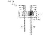
- FIG. 1B shows the airtight terminal in Embodiment 1 based on this invention.
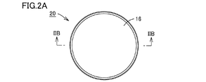
- FIG. 2 is a cross-sectional view taken along the line IIB-IIB in FIG. 2A, showing the aluminum electrolytic capacitor in Embodiment 1 based on the present invention.
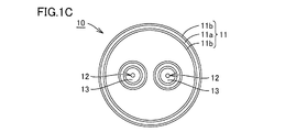
- FIG. 2 is a bottom view which shows the aluminum electrolytic capacitor in Embodiment 1 based on this invention.
- FIG. 4 is a cross-sectional view taken along line IVB-IVB in FIG. 4A, showing the aluminum electrolytic capacitor in Embodiment 2 based on the present invention. It is a bottom view which shows the aluminum electrolytic capacitor in Embodiment 2 based on this invention.
- FIG. 5B is a cross-sectional view taken along the line VB-VB in FIG. 5A showing the airtight terminal in the third embodiment based on the present invention. It is a flowchart which shows the manufacturing method of the aluminum electrolytic capacitor in embodiment based on this invention. It is a flowchart which shows the manufacturing method of the aluminum electrolytic capacitor in embodiment based on this invention. It is a top view which shows the airtight terminal in Embodiment 4 based on this invention.
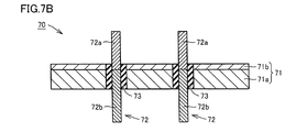
- FIG. 7B is a cross-sectional view taken along line VIIB-VIIB in FIG. 7A showing the airtight terminal in the fourth embodiment based on the present invention.
- FIG. 9B is a cross-sectional view as viewed from the arrow IXB-IXB in FIG. 9A showing the hermetic terminal in the sixth embodiment based on the present invention. It is a top view which shows the airtight terminal in Embodiment 7 based on this invention. It is a XB-XB arrow directional cross-sectional view in FIG. 10A which shows the airtight terminal in Embodiment 7 based on this invention.
- Embodiment 1 Hereinafter, Embodiment 1 according to the present invention will be described with reference to FIGS. 1A to 2C.
- the hermetic terminal 10 includes a base 11, a lead 12, and an insulating glass 13.
- the upper side in FIG. 1B is referred to as the inner side
- the lower side in FIG. 1B is referred to the outer side, based on the state in which the hermetic terminal is used for the aluminum electrolytic capacitor.
- the base 11 is made of a clad material in which both surfaces of a base material 11a made of an iron-based metal material are covered with a surface material 11b made of aluminum.
- the base 11 has a disk-shaped main body, and a cylindrical portion bent at a right angle from the outer periphery of the main body and extending outward.
- the main body portion is provided with a pair of through holes across the central portion thereof.
- a cylindrical portion which is bent at a right angle so as to surround the through hole and extends outward is provided.
- the base 11 is manufactured by press-molding a clad material.
- the base material 11 a is exposed at the end face of the clad material constituting the base 11.
- Aluminum has corrosion resistance to the electrolytic solution of the aluminum electrolytic capacitor. Although the base material 11a made of an iron-based metal material does not have corrosion resistance to the electrolytic solution, the base material 11a of the base 11 is not exposed on the inner side of the aluminum electrolytic capacitor. It does not elute into the solution.
- a lead 12 passes through each of the two through holes.
- the leads 12 are composed of an outer lead 12b made of an iron-based metal material and an inner lead 12a made of aluminum. One end of the outer lead 12b is butt-joined to one end of the inner lead 12a.
- the joint between the outer lead 12 b and the inner lead 12 a is located inside the through hole and near the inner side.
- the outer lead 12 b occupies a large part, and only a small part on the inner side is constituted by the inner lead 12 a.
- the outer lead 12b is cylindrical.
- the inner lead 12 a is in the form of a flat plate having a rectangular main body.
- the side of the inner lead 12 a joined to the outer lead 12 b is formed so as to gradually decrease in width.
- the butt portion of the inner lead 12a with the outer lead 12b is cylindrical with the same diameter as the outer lead 12b.
- the shape of the inner lead 12a can be changed to various shapes in accordance with the shape of the capacitor element to be joined.
- the iron-based metal material constituting the base material 11a of the base 11 and the outer lead 12b of the lead 12 means a material selected from the group of steel, stainless steel, low carbon steel, Kovar alloy and iron-nickel alloy.
- iron-based metal materials are superior in solderability to aluminum. By using an iron-based metal material for the outer lead, good solderability can be ensured.
- a material which comprises base material 11a and outer lead 12b a material which fulfills the above conditions is preferred. Materials other than iron-based metal materials may be used as long as the material satisfies the above conditions.
- the lead 12 and the base 11 are hermetically sealed by an insulating glass 13. Specifically, the gap between the inner circumferential surface of the through hole of the base 11 and the portion facing the inner circumferential surface of the through hole of the lead 12 is filled with the insulating glass 13.
- the joint between the inner lead 12 a and the outer lead 12 b of the lead 12 is covered with the insulating glass 13.
- the outer lead 12b is not exposed to the inner side because the bonding portion between the inner lead 12a and the outer lead 12b is covered with the insulating glass 13.
- the outer lead 12b made of an iron-based metal does not come in contact with the electrolytic solution.
- the leads 12 only the inner lead 12a made of aluminum having corrosion resistance to the electrolytic solution is in contact with the electrolytic solution, so that the metal is not eluted and the electrolytic solution is not contaminated.
- the coefficient of thermal expansion of the iron-based metal material is the thermal expansion of glass Close to the rate.
- a large part of the volume of the base 11 is a base material 11 a made of an iron-based metal material.
- the outer leads 12 b made of an iron-based metal material.
- the insulating glass 13 is, for example, a low melting glass such as a bismuth-containing glass. By using the low melting glass, it is possible to prevent the aluminum from melting in the step of melting the insulating glass 13 in the furnace to hermetically seal between the base 11 and the lead 12.
- low melting point glass As a specific example of low melting point glass, there is a product name BG-0800 manufactured by Nippon Electric Glass Co., Ltd.
- the softening point of this material is 510 ° C., which is lower than the melting point of aluminum.
- the same material was favorably evaluated in all of glass water resistance evaluation, glass acid resistance evaluation, wettability to an aluminum plate, heat cycle test, and high temperature high humidity test.
- a clad material of aluminum and SUS304 was used as a base, and a lead obtained by arc welding Fe and aluminum was used.
- heating at 125.degree. C. and cooling at -55.degree. C. were repeated, and after a constant cycle, leakage of He was checked.
- the high temperature and high humidity test the sample was placed in an environment at a temperature of 85 ° C. and a humidity of 85%, and the leak was checked after a predetermined time.
- the aluminum electrolytic capacitor 20 is provided with the airtight terminal 10, the capacitor element 15, and the case 16 as shown to FIG. 2B.
- the capacitor element 15 is formed by cylindrically winding an anode aluminum foil having an oxide film formed on the surface, an electrolytic paper impregnated with an electrolytic solution, and an anode aluminum foil.
- An inner lead 12 a is connected to each of the anode aluminum foil and the cathode aluminum foil of the capacitor element 15.
- the case 16 is cylindrical with an internal space and an opening.
- the case 16 is formed of aluminum.
- a capacitor element 15 is accommodated in the case 16.
- the airtight terminal 10 is airtightly crimped to the opening of the case 16.
- the airtight pressure bonding of the case 16 is performed by pressing the base 11 of the airtight terminal 10 into the opening of the case 16.
- case 16 and the airtight terminal 10 are airtightly crimped, airtightness between the case 16 and the airtight terminal 10 can be secured. Further, high airtightness is secured by airtightly sealing between the base 11 and the lead 12 of the airtight terminal 10 with the insulating glass 13. As a result, dry-up of the electrolytic solution in the case 16 can be prevented, and the life of the aluminum electrolytic capacitor can be prolonged.
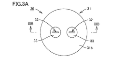
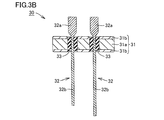
- Embodiment 2 according to the present invention will be described with reference to FIGS. 3A to 4C.
- the hermetic terminal 30 includes a base 31, a lead 32, and an insulating glass 33.
- the base 31 is made of a clad material in which both surfaces of a base material 31a made of an iron-based metal material are covered with a surface material 31b made of aluminum.
- the base 31 is formed in a disk shape.
- the base 31 is provided with a pair of through holes across the central portion thereof. Although the base material 31a is exposed at the end face of the clad material constituting the base 31, the entire surface facing the inner side of the base 31 is covered with the surface material 31b made of aluminum, and the base material 31a is not exposed.
- Aluminum has corrosion resistance to the electrolytic solution of the aluminum electrolytic capacitor. Although the base material 31a made of an iron-based metal material does not have corrosion resistance to the electrolytic solution, the base material 31a of the base 31 is not exposed on the inner side of the aluminum electrolytic capacitor. It does not elute into the solution.
- a lead 32 passes through each of the two through holes.
- the leads 32 are composed of an outer lead 32b made of an iron-based metal material and an inner lead 32a made of aluminum. One end of the outer lead 32b is butt-joined to one end of the inner lead 32a.
- the joint between the outer lead 32b and the inner lead 32a is located inside the through hole and near the inner side.
- the outer lead 32 b occupies a large part, and only a small part on the inner side is constituted by the inner lead 32 a.
- the outer lead 32b is cylindrical.
- the inner lead 32a is in the form of a flat plate having a rectangular main body.
- the side of the inner lead 32a joined to the outer lead 32b is formed to have a gradually smaller width.
- the butted portion of the inner lead 32a with the outer lead 32b has a cylindrical shape having the same diameter as the outer lead 32b.
- the shape of the inner lead 32a can be changed to various shapes in accordance with the shape of the capacitor element to be joined.
- the leads 32 and the base 31 are hermetically sealed by an insulating glass 33. Specifically, the gap between the inner peripheral surface of the through hole of the base 31 and the portion facing the inner peripheral surface of the through hole of the lead 32 is filled with the insulating glass 33.
- the joint between the inner lead 32 a and the outer lead 32 b of the lead 32 is covered with the insulating glass 33.
- the outer lead 32 b is not exposed to the inner side because the bonding portion between the inner lead 32 a and the outer lead 32 b is covered with the insulating glass 33.
- the outer lead 32b does not come in contact with the electrolytic solution.
- the inner lead 32a made of aluminum having corrosion resistance to the electrolytic solution is in contact with the electrolytic solution, so that the metal is not eluted and the electrolytic solution is not contaminated.
- the aluminum electrolytic capacitor 40 is provided with the airtight terminal 30, the capacitor
- the capacitor element 35 is one in which an anode aluminum foil having an oxide film formed on the surface, an electrolytic paper impregnated with an electrolytic solution, and an anode aluminum foil are cylindrically wound.
- An inner lead 32 a is connected to each of the anode aluminum foil and the cathode aluminum foil of the capacitor element 35.
- the case 36 is cylindrical with an internal space and an opening.
- the case 36 is formed of aluminum.
- a capacitor element 35 is accommodated in the case 36.
- An airtight terminal 30 is airtightly attached to the opening of the case 36.
- the airtight sealing of the case 36 is performed by welding the end inner peripheral surface of the case 36 and the outer peripheral surface of the base 31 without a gap over the entire circumference. More specifically, the end inner peripheral surface of the case 36 and the outer peripheral surface of the surface material 31 b on the inner side of the base 31 are welded. Resistance welding or laser welding can be used in the welding process.
- case 36 and the airtight terminal 30 are hermetically sealed, airtightness between the case 36 and the airtight terminal 30 can be secured. Further, high airtightness is secured by airtightly sealing between the base 31 and the lead 32 of the airtight terminal 30 by the insulating glass 33. As a result, dry-up of the electrolytic solution in the case 36 can be prevented, and the life of the aluminum electrolytic capacitor can be prolonged.
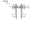
- the hermetic terminal 50 includes a base 51, a lead 52, and an insulating glass 53.
- the base 51 is made of a clad material in which one surface of a base material 51a made of an iron-based metal material is covered with a surface material 51b made of aluminum.
- the base 51 is formed in a disk shape.
- the base 51 is provided with a pair of through holes.
- An enlarged diameter portion 51 s is provided on the outer peripheral surface of the base 51.
- An end of the case of the aluminum electrolytic capacitor on the opening side is in contact with the enlarged diameter portion 51s.
- the interface between the base material 51a and the surface material 51b is located within the thickness of the enlarged diameter portion 51s.
- the base material 51a is exposed at the end face of the clad material constituting the base 51, the entire surface toward the inner side of the inner peripheral side of the enlarged diameter portion 51s of the base 51 is covered with the surface material 51b made of aluminum, The base material 51a is not exposed.
- the surface on the inner side of the enlarged diameter portion 51s and the surface on the inner side of the enlarged diameter portion 51s of the base 51 are all covered with aluminum.
- Aluminum has corrosion resistance to the electrolytic solution of the aluminum electrolytic capacitor. Although the base material 51a made of an iron-based metal material does not have corrosion resistance to the electrolyte solution, the base material 51a of the base 51 is not exposed on the inner side of the aluminum electrolytic capacitor. Does not elute.
- a lead 52 passes through each of the two through holes.
- the lead 52 is composed of an outer lead 52b made of an iron-based metal material and an inner lead 52a made of aluminum. One end of the outer lead 52b is butt-joined to one end of the inner lead 52a.
- the joint between the outer lead 52 b and the inner lead 52 a is located inside the through hole and near the inner side.
- the outer lead 52b occupies a large part, and only a small part on the inner side is constituted by the inner lead 52a.
- the outer lead 52b and the inner lead 52a are cylindrical.
- the shape of the inner lead 52a can be changed to various shapes in accordance with the shape of the capacitor element to be joined.
- the lead 52 and the base 51 are hermetically sealed by an insulating glass 53. Specifically, a gap between the inner circumferential surface of the through hole of the base 51 and the portion facing the inner circumferential surface of the through hole of the lead 52 is filled with the insulating glass 53.
- the joint between the inner lead 52 a and the outer lead 52 b of the lead 52 is covered with the insulating glass 53.
- the outer lead 52b is not exposed to the inner side because the bonding portion between the inner lead 52a and the outer lead 52b is covered with the insulating glass 53.
- the outer lead 52b does not come in contact with the electrolytic solution.
- the inner lead 52a made of aluminum having corrosion resistance to the electrolytic solution is in contact with the electrolytic solution, so that the metal does not elute to contaminate the electrolytic solution.
- a case and a capacitor element (not shown) are attached to the hermetic terminal 50 to form an aluminum electrolytic capacitor.
- the airtight terminal 50 is airtightly attached to the opening of the case.
- the hermetic sealing of the case is performed by resistance welding or laser welding without gaps around the entire circumference between the inner peripheral surface of the end of the case and the outer peripheral surface on the inner side of the enlarged diameter portion 51s of the base 51.
- the airtightness between the case and the airtight terminal 50 can be secured. Further, high airtightness is secured by airtightly sealing between the base 51 of the airtight terminal 50 and the lead 52 with the insulating glass 33. As a result, the dry-up of the electrolytic solution in the case can be prevented, and the life of the aluminum electrolytic capacitor can be prolonged.
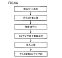
- the metal plate in which the surface of the base material 11a made of iron-based metal is covered with the surface material 11b made of aluminum is press-formed and passed A base 11 with holes is manufactured.
- the inner lead 12a made of aluminum is butt-joined to one end of the outer lead 12b made of iron-based metal, and the lead 12 is manufactured.
- the lead 12 is inserted into the through hole of the base 11, and a tablet of the insulating glass 13 made of low melting glass having a melting point lower than that of aluminum is set in the gap between the lead 12 and the base 11.
- the set base 11, the lead 12 and the tablet of the insulating glass 13 are passed through a heating furnace adjusted to a temperature below the melting point of aluminum, and the lead 12 and the base 11 are sealed by the insulating glass 13 An airtight terminal is completed.
- a capacitor comprising an aluminum foil for the anode having an oxide film on the surface, an electrolytic paper impregnated with an electrolytic solution, and an aluminum foil for the cathode.
- the element 15 is electrically connected to the hermetic terminal 10.
- the capacitor element 15 is inserted into the aluminum case 16 having an opening, and the outer peripheral surface of the base 11 and the inner peripheral surface of the opening of the case 16 are fixed.
- the base 11 is pressed into the case 16 by pressure.
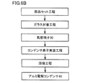
- the metal plate in which the surface of the base material 31a made of iron-based metal is covered with the surface material 31b made of aluminum is press-formed and passed Manufacture a base with holes.
- the inner lead 32a made of aluminum is butt-joined to one end of the outer lead 32b made of an iron-based metal material to manufacture the lead 32.
- the lead 32 is inserted into the through hole of the base 31, and a tablet of insulating glass 33 made of low melting glass having a melting point lower than that of aluminum is set in the gap between the lead 32 and the base 31.
- the set base 31, the leads 32 and the tablet of the insulating glass 33 are passed through a heating furnace adjusted to a temperature below the melting point of aluminum, and the leads 32 and the base 31 are sealed by the insulating glass 33 Manufacture airtight terminals.
- a capacitor comprising an aluminum foil for the anode having an oxide film on the surface, an electrolytic paper impregnated with an electrolytic solution, and an aluminum foil for the cathode.
- the element 35 is electrically connected to the hermetic terminal 30.
- the capacitor element 35 is inserted into an aluminum case 36 having an opening, and the outer peripheral surface of the base 31 and the inner peripheral surface of the opening of the case 36 are fixed.
- the outer peripheral surface of the base 31 is resistance-welded or laser welded to the inner peripheral surface of the opening of the case 36 without any gap.
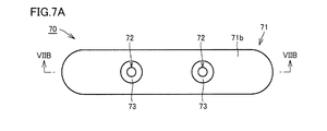
- Embodiment 4 hereinafter, Embodiment 4 according to the present invention will be described with reference to FIGS. 7A and 7B.
- the hermetic terminal 70 includes a base 71, a lead 72, and an insulating glass 73.
- the base 71 is made of a clad material in which one surface of a base material 71a made of an iron-based metal material is covered with a surface material 71b made of aluminum.
- the base 71 is formed in an oval shape having a pair of parallel side surfaces and an arc connecting the side surfaces.
- the base 71 is provided with a pair of through holes.
- the base material 71a is exposed at the end face of the clad material constituting the base 71, the entire surface toward the inner side of the base 71 is covered with the surface material 71b made of aluminum, and the base material 71a is not exposed.
- Aluminum has corrosion resistance to the electrolytic solution of the aluminum electrolytic capacitor. Since the base material 71 a of the base 71 is not exposed to the inside of the aluminum electrolytic capacitor, the base 71 does not elute into the electrolytic solution of the aluminum electrolytic capacitor.
- a lead 72 passes through each of the two through holes.
- the leads 72 are composed of an outer lead 72b made of an iron-based metal material and an inner lead 72a made of aluminum. One end of the outer lead 72b is butt-joined to one end of the inner lead 72a.
- the joint between the outer lead 72b and the inner lead 72a is located inside the through hole and near the inner side.
- the outer lead 72b occupies a large part, and only a small part on the inner side is constituted by the inner lead 72a.
- the outer lead 72b and the inner lead 72a are cylindrical.
- the shape of the inner lead 72a can be changed to various shapes according to the shape of the capacitor element to be joined.
- the lead 72 and the base 71 are hermetically sealed by an insulating glass 73. Specifically, the gap between the inner circumferential surface of the through hole of the base 71 and the portion facing the inner circumferential surface of the through hole of the lead 72 is filled with the insulating glass 73.
- the joint between the inner lead 72 a of the lead 72 and the outer lead 72 b is covered with the insulating glass 73. Since the bonding portion between the inner lead 72a and the outer lead 72b is covered with the insulating glass 73, the outer lead 72b is not exposed to the inner side. As a result, the outer lead 72b does not come in contact with the electrolytic solution. Of the leads 72, only the inner lead 72a made of aluminum having corrosion resistance to the electrolytic solution is in contact with the electrolytic solution, so that the metal does not elute to contaminate the electrolytic solution.
- a case and a capacitor element are attached to the hermetic terminal 70 to form an aluminum electrolytic capacitor.
- the planar shape of the case is an elongated shape corresponding to the planar shape of the base 71 shown in FIG. 7A.
- the airtight terminal 70 is airtightly attached to the opening of the case.
- the hermetic sealing of the case is performed by resistance-welding the inner peripheral surface of the end of the case and the outer peripheral surface of the base 71 along the entire circumference without any gap. More specifically, the end inner peripheral surface of the case and the outer peripheral surface of the surface material 71b of the base 71 are welded. Resistance welding or laser welding can be used in the welding process.
- the case and the airtight terminal 70 are hermetically sealed, airtightness between the case and the airtight terminal 70 can be secured.
- the case has a non-cylindrical shape, but high airtightness can be ensured even with an aluminum electrolytic capacitor having such a case.
- high airtightness is secured by airtightly sealing between the base 71 and the lead 72 of the airtight terminal 70 by the insulating glass 73. As a result, the dry-up of the electrolytic solution in the case can be prevented, and the life of the aluminum electrolytic capacitor can be prolonged.
- the hermetic terminal 80 includes a base 81, a lead 82, and an insulating glass 83.
- the base 81 is a clad obtained by covering one surface of a base material 81a made of an iron-based metal material with a surface material 81b made of aluminum and inserting a thin plate of nickel as an intermediate layer 81c between the material 81a and the surface material 81b. It is made of wood.
- the base 81 is formed in a substantially rectangular shape having a pair of parallel side surfaces and an arc connecting the side surfaces.
- SUS304 is used as the iron-based metal material.
- the base 81 is provided with a pair of through holes.
- the surface material 81 b has an enlarged portion 81 s spread outward. Although the base material 81a and the intermediate layer 81c are exposed at the end face of the clad material constituting the base 81, the surface directed to the inner side of the inner peripheral side of the enlarged portion 81s of the base 81 is a surface material 81b made of aluminum. The base material 81a and the intermediate layer 81c are not exposed.
- Aluminum has corrosion resistance to the electrolytic solution of the aluminum electrolytic capacitor. Since the base material 81a and the intermediate layer 81c of the base 81 are not exposed on the inner side of the aluminum electrolytic capacitor, the base material 81a does not elute into the electrolytic solution of the aluminum electrolytic capacitor.
- a lead 82 passes through each of the two through holes.
- the lead 82 is composed of an outer lead 82b made of an iron-based metal material and an inner lead 82a made of aluminum. One end of the outer lead 82b is butt-joined to one end of the inner lead 82a.
- the joint between the outer lead 82b and the inner lead 82a is located inside the through hole and closer to the inner side.
- the outer lead 82b occupies a large part, and only a small part on the inner side is constituted by the inner lead 82a.
- the outer lead 82b and the inner lead 82a are cylindrical.
- the inner lead 82a is larger in diameter than the outer lead 82b.
- the shape of the inner lead 82a can be changed to various shapes according to the shape of the capacitor element to be joined.
- the lead 82 and the base 81 are hermetically sealed by an insulating glass 83. Specifically, the gap between the inner peripheral surface of the through hole of the base 81 and the portion facing the inner peripheral surface of the through hole of the lead 82 is filled with the insulating glass 83.
- the joint between the inner lead 82 a and the outer lead 82 b of the lead 82 is covered with the insulating glass 83.
- the outer lead 82b is not exposed to the inner side because the bonding portion between the inner lead 82a and the outer lead 82b is covered with the insulating glass 83.
- the outer lead 82b does not contact the electrolytic solution.
- the inner lead 82a made of aluminum having corrosion resistance to the electrolytic solution is in contact with the electrolytic solution, so that the metal is not eluted and the electrolytic solution is not contaminated.
- a case and a capacitor element (not shown) are attached to the airtight terminal 80 to constitute an aluminum electrolytic capacitor.
- the planar shape of the case is an elongated shape corresponding to the planar shape of the base 81 shown in FIG. 8A.
- the airtight terminal 80 is airtightly attached to the opening of the case. In the hermetic sealing of the case, resistance welding or laser welding is performed without gaps around the entire circumference between the inner peripheral surface of the end of the case and the outer peripheral surface on the inner side of the enlarged portion 81s of the base 81.
- the case and the airtight terminal 80 are hermetically sealed, the airtightness between the case and the airtight terminal 80 can be secured.
- the case has a non-cylindrical shape, but high airtightness can be ensured even with an aluminum electrolytic capacitor having such a case.
- high airtightness is secured by airtightly sealing between the base 81 of the airtight terminal 80 and the lead 82 with the insulating glass 83. As a result, the dry-up of the electrolytic solution in the case can be prevented, and the life of the aluminum electrolytic capacitor can be prolonged.
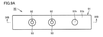
- the hermetic terminal 90 includes a base 91, a lead 92, and an insulating glass 93.
- the base 91 is made of a clad material in which one surface of a base material 91a made of an iron-based metal material is covered with a surface material 91b made of aluminum.
- the base 91 is formed in a rectangular shape in plan view.
- the base 91 is provided with three through holes at equal intervals.
- the base material 91a is exposed at the end face of the clad material constituting the base 91, the entire surface facing the inner side of the base 91 is covered with the surface material 91b made of aluminum, and the base material 91a is not exposed.
- Aluminum has corrosion resistance to the electrolytic solution of the aluminum electrolytic capacitor. Since the base material 91a of the base 91 is not exposed on the inner side of the aluminum electrolytic capacitor, the base material 91a does not elute into the electrolytic solution of the aluminum electrolytic capacitor.
- a lead 92 passes through each of two adjacent through holes of the three through holes.
- the lead 92 includes an outer lead 92b made of an iron-based metal material and an inner lead 92a made of aluminum. One end of the outer lead 92b is butt-joined to one end of the inner lead 92a.
- the joint between the outer lead 92 b and the inner lead 92 a is located inside the through hole and near the inner side.
- the outer lead 92b occupies a large part, and only a small part on the inner side is constituted by the inner lead 92a.
- the outer lead 92b and the inner lead 92a are cylindrical.
- the shape of the inner lead 92a can be changed to various shapes according to the shape of the capacitor element to be joined.
- the lead 92 and the base 91 are hermetically sealed by an insulating glass 93. Specifically, the gap between the inner circumferential surface of the through hole of the base 91 and the portion facing the inner circumferential surface of the through hole of the lead 92 is filled with the insulating glass 93.
- the joint between the inner lead 92 a and the outer lead 92 b of the lead 92 is covered with the insulating glass 93.
- the outer lead 92 b is not exposed to the inner side because the bonding portion between the inner lead 92 a and the outer lead 92 b is covered with the insulating glass 93.
- the outer lead 92b does not come in contact with the electrolytic solution.
- the inner lead 92a made of aluminum having corrosion resistance to the electrolytic solution is in contact with the electrolytic solution, so that the metal is not eluted and the electrolytic solution is not contaminated.
- the third through hole 91 h is provided to release the vapor of the electrolyte solvent when the internal pressure becomes excessive.
- a valve or a lid or a plug which is punctured to the outside is attached.
- a case and a capacitor element are attached to the hermetic terminal 90 to form an aluminum electrolytic capacitor.
- the planar shape of the case is a rectangle corresponding to the planar shape of the base 91 shown in FIG. 9A.
- An airtight terminal 90 is airtightly attached to the opening of the case.
- the hermetic sealing of the case is performed by welding the end inner peripheral surface of the case and the outer peripheral surface of the base 91 all around without gap. More specifically, the end inner peripheral surface of the case and the outer peripheral surface of the surface material 91 b of the base 91 are welded. Resistance welding or laser welding can be used in the welding process.
- the case and the airtight terminal 90 are hermetically sealed, airtightness between the case and the airtight terminal 90 can be secured.
- the case has a non-cylindrical shape, but high airtightness can be ensured even with an aluminum electrolytic capacitor having such a case.
- the space between the base 91 of the airtight terminal 90 and the lead 92 is also airtightly sealed by the insulating glass 93 to ensure high airtightness. As a result, the dry-up of the electrolytic solution in the case can be prevented, and the life of the aluminum electrolytic capacitor can be prolonged.
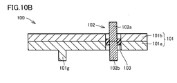
- the hermetic terminal 100 includes a base 101, a lead 102, and an insulating glass 103.
- the base 101 is made of a clad material in which one surface of a base material 101a made of an iron-based metal material is covered with a surface material 101b made of aluminum.
- the base 101 is formed in a disk shape.
- the base 101 is provided with one through hole.
- the base material 101a is exposed at the end face of the clad material constituting the base 101, the entire surface toward the inner side of the base 101 is covered with the surface material 101b made of aluminum, and the base material 101a is not exposed.
- Aluminum has corrosion resistance to the electrolytic solution of the aluminum electrolytic capacitor. Since the base material 101a of the base 101 is not exposed on the inner side of the aluminum electrolytic capacitor, the base material 101a does not elute into the electrolytic solution of the aluminum electrolytic capacitor.
- a protrusion 101 g is provided on the outer surface of the base 101.
- the protrusion 101 g is configured in a cylindrical shape.
- the ground side of the capacitor element is electrically connected to the base 101 directly or through a case.
- the lead 102 includes an outer lead 102b made of an iron-based metal material and an inner lead 102a made of aluminum. One end of the outer lead 102b is butt-joined to one end of the inner lead 102a.
- the outer lead 102b and the inner lead 102a have a cylindrical shape.
- a capacitor element is electrically connected to the inner side of the inner lead 102a.
- the shape of the inner lead can be changed to various shapes according to the shape of the capacitor element to be joined.
- the lead 102 and the base 101 are hermetically sealed by an insulating glass 103.
- a part of the gap between the inner circumferential surface of the through hole of the base 101 and the portion facing the inner circumferential surface of the through hole of the lead 102 is filled with the insulating glass 103.
- the insulating glass 103 As shown in FIG. 10B, what is filled with the insulating glass 103 is a part of the through holes in the longitudinal direction.
- the insulating glass 103 may extend over the entire length of the through hole in the longitudinal direction.
- the joint between the inner lead 102 a of the lead 102 and the outer lead 102 b is covered with the insulating glass 103.
- the outer lead 102b is not exposed to the inner side because the bonding portion between the inner lead 102a and the outer lead 102b is covered with the insulating glass 103.
- the outer lead 102b does not come in contact with the electrolytic solution.
- the inner lead 102a made of aluminum having corrosion resistance to the electrolytic solution is in contact with the electrolytic solution, so that the metal is not eluted and the electrolytic solution is not contaminated.
- a case and a capacitor element are attached to the hermetic terminal 100 to form an aluminum electrolytic capacitor.
- the airtight terminal 100 is airtightly attached to the opening of the case.
- the airtight sealing of the case is performed by welding the end inner peripheral surface of the case and the outer peripheral surface of the base 101 without a gap over the entire circumference. More specifically, the end inner peripheral surface of the case and the outer peripheral surface of the surface material 101 b of the base 101 are welded. Resistance welding or laser welding can be used in the welding process.
- the case and the airtight terminal 100 are hermetically sealed, airtightness between the case and the airtight terminal 100 can be secured. Further, high airtightness is secured by airtightly sealing between the base 101 and the lead 102 of the airtight terminal 100 with the insulating glass 103. As a result, the dry-up of the electrolytic solution in the case can be prevented, and the life of the aluminum electrolytic capacitor can be prolonged.
- An airtight terminal, an aluminum electrolytic capacitor, and a method of manufacturing an aluminum electrolytic capacitor can be provided.
Abstract
Description
以下、本発明に係る実施の形態1について、図1Aから図2Cを参照して説明する。 Embodiment 1
Hereinafter, Embodiment 1 according to the present invention will be described with reference to FIGS. 1A to 2C.
以下、本発明に係る実施の形態2について、図3Aから図4Cを参照して説明する。 Second Embodiment
Hereinafter, Embodiment 2 according to the present invention will be described with reference to FIGS. 3A to 4C.
以下、本発明に係る実施の形態3について、図5Aおよび図5Bを参照して説明する。 Third Embodiment
The third embodiment according to the present invention will be described below with reference to FIGS. 5A and 5B.
実施の形態1および2の気密端子およびアルミ電解コンデンサの製造方法について図6Aおよび図6Bを用いて説明する。 (Production method)
A method of manufacturing the hermetic terminal and the aluminum electrolytic capacitor of Embodiments 1 and 2 will be described with reference to FIGS. 6A and 6B.
以下、本発明に係る実施の形態4について、図7Aおよび図7Bを参照して説明する。 Embodiment 4
Hereinafter, Embodiment 4 according to the present invention will be described with reference to FIGS. 7A and 7B.
以下、本発明に係る実施の形態5について、図8を参照して説明する。図8に示すように、本実施の形態に係る気密端子80は、ベース81と、リード82と、絶縁ガラス83とを備えている。 Fifth Embodiment
The fifth embodiment according to the present invention will be described below with reference to FIG. As shown in FIG. 8, the
以下、本発明に係る実施の形態6について、図9Aおよび図9Bを参照して説明する。 Sixth Embodiment
Sixth Embodiment A sixth embodiment of the present invention will be described below with reference to FIGS. 9A and 9B.
以下、本発明に係る実施の形態7について、図10Aおよび図10Bを参照して説明する。 Seventh Embodiment
Seventh Embodiment A seventh embodiment of the present invention will be described below with reference to FIGS. 10A and 10B.
Claims (12)
- アルミ電解コンデンサに気密固着される気密端子であって、
通孔を有し、前記アルミ電解コンデンサのケースに取り付けられる導電性を有する複合材からなるベースと、
前記べースの前記通孔に挿通された、導電性を有する複合材からなる少なくとも1つのリードと、
前記ベースと前記リードとの間を気密封着する絶縁ガラスとを備え、
前記ベースおよび前記リードの、前記ケース内部の電解液に接触する部分の表面は、電解液に対して耐蝕性を有する金属材料で構成されている、気密端子。 An airtight terminal airtightly fixed to an aluminum electrolytic capacitor,
A base made of a conductive composite material having a through hole and attached to the case of the aluminum electrolytic capacitor;
At least one lead made of a conductive composite material inserted through the through hole of the base;
An insulating glass for hermetically sealing between the base and the lead;
An airtight terminal, wherein the surface of the base and the portion of the lead in contact with the electrolytic solution inside the case are made of a metal material having corrosion resistance to the electrolytic solution. - 前記ベースは、鉄基金属材からなる母材と、前記母材の少なくとも一方の表面を覆うアルミニウムからなる表面材とを有する、請求項1に記載の気密端子。 The airtight terminal according to claim 1, wherein the base has a base material made of an iron-based metal material and a surface material made of aluminum covering at least one surface of the base material.
- 前記リードは、鉄基金属材からなるアウターリードと、前記アウターリードの片端に突合せ接合したアルミニウムからなるインナーリードとを有する、請求項1または請求項2に記載の気密端子。 The airtight terminal according to claim 1, wherein the lead has an outer lead made of an iron-based metal material and an inner lead made of aluminum butt-joined to one end of the outer lead.
- 前記絶縁ガラスは融点がアルミニウムの融点より低い低融点ガラスからなる、請求項1から請求項3のいずれかに記載の気密端子。 The airtight terminal according to any one of claims 1 to 3, wherein the insulating glass is a low melting glass having a melting point lower than that of aluminum.
- 請求項1から請求項4のいずれかに記載の気密端子と、
酸化被膜を表面に有する陽極用アルミニウム箔と、
電解液を含浸させた電解紙と、
陰極用アルミニウム箔と、
前記陽極用アルミニウム箔と、前記電解紙と、前記陰極用アルミニウム箔とが内部に収容され、前記気密端子が気密封着されるアルミニウム製のケースと、を備え、
前記陽極用アルミニウム箔および前記陰極用アルミニウム箔の少なくともいずれか一方は、前記インナーリードに電気的に接続されている、アルミ電解コンデンサ。 The airtight terminal according to any one of claims 1 to 4;
Aluminum foil for an anode having an oxide film on the surface,
An electrolytic paper impregnated with an electrolytic solution,
Aluminum foil for cathode,
And an aluminum case in which the aluminum foil for the anode, the electrolytic paper, and the aluminum foil for the cathode are accommodated, and the airtight terminal is hermetically sealed.
An aluminum electrolytic capacitor, wherein at least one of the aluminum foil for anode and the aluminum foil for cathode is electrically connected to the inner lead. - 前記陽極用アルミニウム箔および前記陰極用アルミニウム箔の一方は、前記インナーリードに電気的に接続され、前記陽極用アルミニウム箔および前記陰極用アルミニウム箔の他方は前記ベースに電気的に接続されている、請求項5に記載のアルミ電解コンデンサ。 One of the aluminum foil for the anode and the aluminum foil for the cathode is electrically connected to the inner lead, and the other of the aluminum foil for the anode and the aluminum foil for the cathode is electrically connected to the base. The aluminum electrolytic capacitor according to claim 5.
- 前記少なくとも1つのリードは2つのリードを備え、
前記2つのリードの一方は前記陽極用アルミニウム箔に接続され、前記2つのリードの他方は前記陰極用アルミニウム箔に接続されている、請求項5に記載のアルミ電解コンデンサ。 The at least one lead comprises two leads,
The aluminum electrolytic capacitor according to claim 5, wherein one of the two leads is connected to the aluminum foil for an anode, and the other of the two leads is connected to the aluminum foil for a cathode. - 前記ベースと前記ケースとは圧着されている、請求項5から請求項7のいずれかに記載のアルミ電解コンデンサ。 The aluminum electrolytic capacitor according to any one of claims 5 to 7, wherein the base and the case are crimped.
- 前記ベースと前記ケースとは溶接接合されている、請求項5から請求項7のいずれかに記載のアルミ電解コンデンサ。 The aluminum electrolytic capacitor according to any one of claims 5 to 7, wherein the base and the case are joined by welding.
- 鉄基金属材からなる母材の表面をアルミニウムで覆った金属板を、プレス成形して通孔を有するベースを製造する工程と、
鉄基金属材からなるアウターリードの片端にアルミニウムからなるインナーリードを突合せ接合してリードを製造する工程と、
前記ベースの前記通孔に前記リードを挿入し、前記リードと前記ベースとの隙間に、融点がアルミニウムより低い低融点ガラスからなる絶縁ガラスのタブレットをセットする工程と、
前記セットされた前記ベース、前記リードおよび前記タブレットをアルミニウムの融点以下の温度に調温された加熱炉に通して、前記リードと前記ベースとを前記絶縁ガラスによって封着して気密端子を製造する工程と、
酸化被膜を表面に有する陽極用アルミニウム箔と、電解液を含浸させた電解紙と、陰極用アルミニウム箔とからなるコンデンサ素子を、前記気密端子に電気的に接続する工程と、
開口部を有するアルミニウム製のケースに前記コンデンサ素子を挿入し、前記ベースの外周面と前記ケースの前記開口部の内周面とを固定する工程とを備えた、アルミ電解コンデンサの製造方法。 Manufacturing a base having through holes by press-forming a metal plate in which the surface of a base material made of an iron-based metal material is covered with aluminum;
Manufacturing a lead by butt-joining an inner lead made of aluminum to one end of an outer lead made of an iron-based metal material;
Inserting the lead into the through hole of the base, and setting a tablet of insulating glass made of low melting glass having a melting point lower than that of aluminum in the gap between the lead and the base;
The set base, the lead, and the tablet are passed through a heating furnace adjusted to a temperature lower than the melting point of aluminum, and the lead and the base are sealed with the insulating glass to manufacture an airtight terminal. Process,
Electrically connecting a capacitor element comprising an aluminum foil for the anode having an oxide film on the surface, an electrolytic paper impregnated with an electrolytic solution, and an aluminum foil for the cathode to the airtight terminal;
And a step of inserting the capacitor element into an aluminum case having an opening and fixing the outer peripheral surface of the base and the inner peripheral surface of the opening of the case. - 前記ベースの前記外周面と前記ケースの前記開口部の前記内周面とを固定する工程は、前記ベースが前記ケースの前記開口部に圧入されることで前記ベースが前記ケースに圧着される工程を含む、請求項10に記載のアルミ電解コンデンサの製造方法。 In the step of fixing the outer peripheral surface of the base and the inner peripheral surface of the opening of the case, the base is pressed into the opening of the case and the base is crimped to the case. The method of manufacturing an aluminum electrolytic capacitor according to claim 10, comprising:
- 前記ベースの前記外周面と前記ケースの前記開口部の前記内周面とを固定する工程は、前記ベースの前記外周面が前記ケースの前記開口部の前記内周面に隙間なく抵抗溶接またはレーザー溶接される工程を含む、請求項10に記載のアルミ電解コンデンサの製造方法。 In the step of fixing the outer peripheral surface of the base and the inner peripheral surface of the opening of the case, the outer peripheral surface of the base is resistance welded or laser without any gap to the inner peripheral surface of the opening of the case. The method of manufacturing an aluminum electrolytic capacitor according to claim 10, comprising the step of welding.
Priority Applications (5)
| Application Number | Priority Date | Filing Date | Title |
|---|---|---|---|
| CN201680031455.7A CN107636781B (en) | 2015-06-03 | 2016-06-02 | Hermetic terminal, aluminum electrolytic capacitor, and method for manufacturing aluminum electrolytic capacitor |
| KR1020177036837A KR102373601B1 (en) | 2015-06-03 | 2016-06-02 | Airtight terminal, aluminum electrolytic capacitor and manufacturing method of aluminum electrolytic capacitor |
| US15/578,444 US10249443B2 (en) | 2015-06-03 | 2016-06-02 | Hermetic terminal, aluminum electrolytic capacitor, and method for manufacturing aluminum electrolytic capacitor |
| JP2017522253A JP6760934B2 (en) | 2015-06-03 | 2016-06-02 | Manufacturing method of airtight terminals, aluminum electrolytic capacitors and aluminum electrolytic capacitors |
| EP16803461.9A EP3306632B1 (en) | 2015-06-03 | 2016-06-02 | Airtight terminal, aluminum electrolytic capacitor and method for manufacturing aluminum electrolytic capacitor |
Applications Claiming Priority (2)
| Application Number | Priority Date | Filing Date | Title |
|---|---|---|---|
| JP2015-112734 | 2015-06-03 | ||
| JP2015112734 | 2015-06-03 |
Publications (1)
| Publication Number | Publication Date |
|---|---|
| WO2016195027A1 true WO2016195027A1 (en) | 2016-12-08 |
Family
ID=57440514
Family Applications (1)
| Application Number | Title | Priority Date | Filing Date |
|---|---|---|---|
| PCT/JP2016/066438 WO2016195027A1 (en) | 2015-06-03 | 2016-06-02 | Airtight terminal, aluminum electrolytic capacitor and method for manufacturing aluminum electrolytic capacitor |
Country Status (6)
| Country | Link |
|---|---|
| US (1) | US10249443B2 (en) |
| EP (1) | EP3306632B1 (en) |
| JP (1) | JP6760934B2 (en) |
| KR (1) | KR102373601B1 (en) |
| CN (1) | CN107636781B (en) |
| WO (1) | WO2016195027A1 (en) |
Cited By (3)
| Publication number | Priority date | Publication date | Assignee | Title |
|---|---|---|---|---|
| JP2018181665A (en) * | 2017-04-17 | 2018-11-15 | ショット日本株式会社 | Airtight terminal |
| JP2019012723A (en) * | 2017-06-29 | 2019-01-24 | ニチコン株式会社 | Electronic component and manufacturing method thereof |
| WO2020027114A1 (en) | 2018-08-01 | 2020-02-06 | ショット日本株式会社 | Airtight terminal |
Families Citing this family (2)
| Publication number | Priority date | Publication date | Assignee | Title |
|---|---|---|---|---|
| JP7170214B2 (en) * | 2020-03-18 | 2022-11-14 | ショット日本株式会社 | Airtight terminal and contact device using the airtight terminal |
| TWI804854B (en) * | 2021-04-28 | 2023-06-11 | 至美電器股份有限公司 | electrolytic capacitor |
Citations (4)
| Publication number | Priority date | Publication date | Assignee | Title |
|---|---|---|---|---|
| JPH08162188A (en) * | 1994-12-08 | 1996-06-21 | Fuji Denka:Kk | Airtight terminal |
| JP2000182907A (en) * | 1998-12-21 | 2000-06-30 | Sanyo Electric Co Ltd | Solid electrolytic capacitor |
| JP2010114132A (en) * | 2008-11-04 | 2010-05-20 | Nec Schott Components Corp | Plating method for airtight terminal |
| JP2012084626A (en) * | 2010-10-08 | 2012-04-26 | Sanyo Electric Co Ltd | Manufacturing method of electrolytic capacitor and electrolytic capacitor |
Family Cites Families (9)
| Publication number | Priority date | Publication date | Assignee | Title |
|---|---|---|---|---|
| US3600017A (en) * | 1968-02-26 | 1971-08-17 | Isotronics Inc | Hermetic metal-to-glass seals |
| US4476517A (en) * | 1983-10-07 | 1984-10-09 | Sprague Electric Company | Aluminum electrolytic capacitor |
| JP2631130B2 (en) * | 1988-06-15 | 1997-07-16 | 日本ケミコン株式会社 | Aluminum electrolytic capacitors |
| JPH02158066A (en) * | 1988-12-09 | 1990-06-18 | Matsushita Electric Ind Co Ltd | Sealed terminal and sealed electrochemical element |
| WO2004030120A2 (en) * | 1999-04-08 | 2004-04-08 | Quallion Llc | Battery case, cover and feedthrough |
| JP2004342649A (en) | 2003-05-13 | 2004-12-02 | Matsushita Electric Ind Co Ltd | Airtight terminal and method of plating the same |
| US10714271B2 (en) * | 2011-07-08 | 2020-07-14 | Fastcap Systems Corporation | High temperature energy storage device |
| US8932750B2 (en) * | 2011-07-27 | 2015-01-13 | Fastcap Systems Corporation | Aluminum housing with a hermetic seal |
| US10403444B2 (en) | 2013-09-16 | 2019-09-03 | Avx Corporation | Wet electrolytic capacitor containing a composite coating |
-
2016
- 2016-06-02 EP EP16803461.9A patent/EP3306632B1/en active Active
- 2016-06-02 US US15/578,444 patent/US10249443B2/en active Active
- 2016-06-02 WO PCT/JP2016/066438 patent/WO2016195027A1/en active Application Filing
- 2016-06-02 KR KR1020177036837A patent/KR102373601B1/en active IP Right Grant
- 2016-06-02 CN CN201680031455.7A patent/CN107636781B/en active Active
- 2016-06-02 JP JP2017522253A patent/JP6760934B2/en active Active
Patent Citations (4)
| Publication number | Priority date | Publication date | Assignee | Title |
|---|---|---|---|---|
| JPH08162188A (en) * | 1994-12-08 | 1996-06-21 | Fuji Denka:Kk | Airtight terminal |
| JP2000182907A (en) * | 1998-12-21 | 2000-06-30 | Sanyo Electric Co Ltd | Solid electrolytic capacitor |
| JP2010114132A (en) * | 2008-11-04 | 2010-05-20 | Nec Schott Components Corp | Plating method for airtight terminal |
| JP2012084626A (en) * | 2010-10-08 | 2012-04-26 | Sanyo Electric Co Ltd | Manufacturing method of electrolytic capacitor and electrolytic capacitor |
Cited By (6)
| Publication number | Priority date | Publication date | Assignee | Title |
|---|---|---|---|---|
| JP2018181665A (en) * | 2017-04-17 | 2018-11-15 | ショット日本株式会社 | Airtight terminal |
| JP2019012723A (en) * | 2017-06-29 | 2019-01-24 | ニチコン株式会社 | Electronic component and manufacturing method thereof |
| WO2020027114A1 (en) | 2018-08-01 | 2020-02-06 | ショット日本株式会社 | Airtight terminal |
| JP2020021827A (en) * | 2018-08-01 | 2020-02-06 | ショット日本株式会社 | Airtight terminal |
| KR20210025127A (en) | 2018-08-01 | 2021-03-08 | 쇼트 니혼 가부시키가이샤 | Airtight terminal |
| EP4199017A2 (en) | 2018-08-01 | 2023-06-21 | Schott Japan Corporation | Lid comprising an airtight terminal sealed by seaming |
Also Published As
| Publication number | Publication date |
|---|---|
| JP6760934B2 (en) | 2020-09-23 |
| KR102373601B1 (en) | 2022-03-14 |
| EP3306632B1 (en) | 2021-04-07 |
| KR20180015664A (en) | 2018-02-13 |
| JPWO2016195027A1 (en) | 2018-04-05 |
| EP3306632A4 (en) | 2019-01-16 |
| EP3306632A1 (en) | 2018-04-11 |
| US10249443B2 (en) | 2019-04-02 |
| CN107636781B (en) | 2020-01-17 |
| US20180151300A1 (en) | 2018-05-31 |
| CN107636781A (en) | 2018-01-26 |
Similar Documents
| Publication | Publication Date | Title |
|---|---|---|
| WO2016195027A1 (en) | Airtight terminal, aluminum electrolytic capacitor and method for manufacturing aluminum electrolytic capacitor | |
| US8163997B2 (en) | Electronic component, lead-wire and their production methods | |
| JP2000077269A (en) | Chip solid electrolytic capacitor and its manufacture | |
| JP2018537868A (en) | Wet electrolytic capacitors with improved volumetric efficiency with filling ports and surface mount terminations | |
| US8896984B2 (en) | Solid electrolytic capacitor | |
| KR20160054811A (en) | Tantalum capacitor and method of preparing the same | |
| US9437367B2 (en) | Method of manufacturing a winding-type solid electrolytic capacitor package structure without using a lead frame | |
| US8699205B2 (en) | Package type multi layer thin film capacitor for high capacitance | |
| KR20150049918A (en) | Tantalum capacitor and method of preparing the same | |
| JP2005353291A (en) | Airtight terminal and manufacturing method of the same | |
| US3947735A (en) | Glass encapsulated capacitor with pressure connected cathode lead | |
| JP6967910B2 (en) | Electronic component packages and electronic component devices | |
| TWI419185B (en) | Electronic parts and their wires, and the manufacturing methods thereof | |
| KR20150053425A (en) | Tantalum capacitor and method of preparing the same | |
| US4771363A (en) | Hermetic sealing for film capacitor | |
| JP2003142614A (en) | Hermetically sealed electronic component | |
| JP2005051051A (en) | Solid electrolytic capacitor and manufacturing method thereof | |
| JP2000268934A (en) | Chip type surge absorbing element and its manufacture | |
| US20210296053A1 (en) | Airtight terminal | |
| JP2018181665A (en) | Airtight terminal | |
| JP2006313649A (en) | Battery and method of sealing its outer and cap cans | |
| JP2001230103A (en) | Glass-sealed thermistor | |
| JPS5923409Y2 (en) | solid electrolytic capacitor | |
| KR20160054810A (en) | Tantalum capacitor and method of preparing the same | |
| JPS6134251B2 (en) |
Legal Events
| Date | Code | Title | Description |
|---|---|---|---|
| 121 | Ep: the epo has been informed by wipo that ep was designated in this application |
Ref document number: 16803461 Country of ref document: EP Kind code of ref document: A1 |
|
| ENP | Entry into the national phase |
Ref document number: 2017522253 Country of ref document: JP Kind code of ref document: A |
|
| WWE | Wipo information: entry into national phase |
Ref document number: 15578444 Country of ref document: US |
|
| NENP | Non-entry into the national phase |
Ref country code: DE |
|
| ENP | Entry into the national phase |
Ref document number: 20177036837 Country of ref document: KR Kind code of ref document: A |
|
| WWE | Wipo information: entry into national phase |
Ref document number: 2016803461 Country of ref document: EP |