WO2016195022A1 - 熱利用装置 - Google Patents
熱利用装置 Download PDFInfo
- Publication number
- WO2016195022A1 WO2016195022A1 PCT/JP2016/066422 JP2016066422W WO2016195022A1 WO 2016195022 A1 WO2016195022 A1 WO 2016195022A1 JP 2016066422 W JP2016066422 W JP 2016066422W WO 2016195022 A1 WO2016195022 A1 WO 2016195022A1
- Authority
- WO
- WIPO (PCT)
- Prior art keywords
- condenser
- evaporator
- inlet
- heat utilization
- heat
- Prior art date
- Legal status (The legal status is an assumption and is not a legal conclusion. Google has not performed a legal analysis and makes no representation as to the accuracy of the status listed.)
- Ceased
Links
Images






Classifications
-
- F—MECHANICAL ENGINEERING; LIGHTING; HEATING; WEAPONS; BLASTING
- F01—MACHINES OR ENGINES IN GENERAL; ENGINE PLANTS IN GENERAL; STEAM ENGINES
- F01D—NON-POSITIVE DISPLACEMENT MACHINES OR ENGINES, e.g. STEAM TURBINES
- F01D25/00—Component parts, details, or accessories, not provided for in, or of interest apart from, other groups
-
- F—MECHANICAL ENGINEERING; LIGHTING; HEATING; WEAPONS; BLASTING
- F01—MACHINES OR ENGINES IN GENERAL; ENGINE PLANTS IN GENERAL; STEAM ENGINES
- F01K—STEAM ENGINE PLANTS; STEAM ACCUMULATORS; ENGINE PLANTS NOT OTHERWISE PROVIDED FOR; ENGINES USING SPECIAL WORKING FLUIDS OR CYCLES
- F01K13/00—General layout or general methods of operation of complete plants
-
- F—MECHANICAL ENGINEERING; LIGHTING; HEATING; WEAPONS; BLASTING
- F01—MACHINES OR ENGINES IN GENERAL; ENGINE PLANTS IN GENERAL; STEAM ENGINES
- F01K—STEAM ENGINE PLANTS; STEAM ACCUMULATORS; ENGINE PLANTS NOT OTHERWISE PROVIDED FOR; ENGINES USING SPECIAL WORKING FLUIDS OR CYCLES
- F01K27/00—Plants for converting heat or fluid energy into mechanical energy, not otherwise provided for
- F01K27/02—Plants modified to use their waste heat, other than that of exhaust, e.g. engine-friction heat
Definitions
- the adjacent evaporators and the condensers must be arranged with a slight gap between them. When these gaps become dead spaces, there is a possibility that downsizing of the entire apparatus may be hindered.
- a heat utilization apparatus of the present invention is provided with an evaporator that recovers heat from a high-temperature heat medium flowing through a high-temperature flow path and heats the working medium in a circulation path through which the working medium circulates.
- An expander that expands the working medium generated to generate a driving force, a condenser that cools and condenses the working medium that has passed through the expander with a low-temperature heat medium that flows through the low-temperature flow path, and an operation that passes through the condenser A Rankine circuit in which a pump for pumping a medium toward the evaporator is inserted at least in sequence, and a housing in which the Rankine circuit is accommodated.
- the heat utilization apparatus of the present invention it is possible to provide a heat utilization apparatus capable of realizing further downsizing while improving maintainability, assemblability, and reliability.
- FIG. 1 The perspective view which shows the connection aspect of the piping side flange of FIG. 3, and piping, (b) It is a top view of Fig.6 (a). It is a perspective view which shows the connection aspect used as the modification of the gas-liquid separator of FIG. 3, and a condenser. It is a perspective view of the heat utilization apparatus which concerns on 2nd Embodiment of this invention. It is a front view of the heat utilization apparatus of FIG. It is a side view of the heat utilization apparatus of FIG. It is a rear view of the heat utilization apparatus of FIG.
- FIG. 1 is a schematic diagram schematically showing the configuration of the heat utilization apparatus 1 of the present embodiment.
- the heat utilization apparatus 1 includes, for example, a Rankine circuit 2 that recovers exhaust heat from a factory or the like (not shown), and a housing 4 that houses the Rankine circuit 2.
- the Rankine circuit 2 is a closed circuit in which an evaporator 8, an expander 10, a condenser 12, a gas-liquid separator 14, and a pump 16 are sequentially inserted in a refrigerant (working medium) circulation path 6 in the refrigerant flow direction. Is configured.
- the evaporator 8 is a heat exchanger that exchanges heat between the refrigerant flowing through the circulation path 6 and the high-temperature heat medium (heat medium) flowing through the high-temperature flow path 18.
- the high-temperature heat medium is, for example, cooling water heated in the factory, that is, hot water.
- the exhaust heat of the factory is absorbed from the high-temperature heat medium to the Rankine circuit 2 side and recovered. Is heated.
- the expander 10 is a scroll type fluid device that generates a rotational driving force by expanding a refrigerant that has been heated by passing through the evaporator 10 and is in a superheated steam state.
- the expander 10 and the pump 16 are connected via a rotating shaft 19, and the rotating shaft 19 converts the rotational driving force generated by the expander 10 between the expander 10 and the pump 16.
- a generator 20 that can be used outside the heat utilization apparatus 1 is integrally connected.
- the generator 20 is a so-called motor generator, and is configured to be able to rotationally drive the rotary shaft 19 by a motor function.
- the condenser 12 is a heat exchanger that heat-exchanges the refrigerant flowing out of the expander 10 and the low-temperature heat medium (heat medium) flowing through the low-temperature flow path 22 to condense and liquefy it.
- the low-temperature heat medium is, for example, outside air or cooling water, and the condenser 12 radiates heat from the high-temperature refrigerant after the power is recovered by the expander 10.
- the gas-liquid separator 14 separates the refrigerant condensed in the condenser 12 into gas-liquid two layers, and only the liquid refrigerant separated here flows out to the pump 16 side.
- the pump 16 is a pump that is rotationally driven via the rotary shaft 19 by the motor function of the generator 20 and the driving force generated by the expander 10.
- the pump 16 pumps the liquid refrigerant separated by the gas-liquid separator 14 to the evaporator 8 side after being condensed by the condenser 12, and suitably circulates the refrigerant in the circulation path 6 of the Rankine circuit 8.
- the evaporator 8 and the condenser 12 are arranged close to each other in the vertical direction Y via a heat insulating member 23 such as a vacuum heat insulating material.
- the condenser 12 is disposed below the evaporator 8.
- the expander 10, the generator 20, and the pump 16 are a single unit 25 housed in a cylindrical housing, and this unit 25 is disposed below the condenser 12, and the bottom of the housing 4. It is fixed to.
- the gas-liquid separator 14 is above the unit 25 and partially overlaps the condenser 12 in the vertical direction Y on the front plate 4a side of the housing 4 when viewed in the depth direction Z of FIG. Are arranged.
- the circulation path 6 includes a pipe 6a flanged to the refrigerant inlet to the evaporator 8, a pipe 6b flanged to the refrigerant outlet to the evaporator 8, a pipe 6c flanged to the refrigerant inlet to the condenser 12, It includes a pipe 6d that is flange-connected to the refrigerant outlet to the condenser 12 and a pipe 6e that is connected to the gas-liquid separator 14 outlet.
- These pipes 6a to 6e are formed by appropriately connecting bellows-like flexible pipes, and the displacement of the above components of the Rankine circuit 2 and the pipes 6a to 6e in the housing 4 is allowed.
- FIG. 6 (a) is a perspective view showing a connection mode between the pipe side flange 6a1 and the pipe 6a
- FIG. 6 (b) is a plan view of FIG. 6 (a).
- the pipe 6a is connected to the outer peripheral portion 6a2 of the pipe-side flange 6a1 by, for example, screwing or welding.
- the flow path 6a3 which changes the flow of a refrigerant
- a pressure guiding path 6a4 capable of guiding the refrigerant pressure in the flow path 6a3 may be drilled in the pipe side flange 6a1, and the pressure guiding path 6a4 may be opened in the outer peripheral part 6a2.
- the pressure guiding path 6 a 4 is closed by the joint 27.
- the joint 27 can be connected to a pressure switch, a pressure sensor, a safety valve, a shut-off valve for charging / discharging the refrigerant (all not shown), and the like.
- the pipe side flanges 6b1 and 6c1 are also formed as shown in FIGS. 6 (a) and 6 (b).
- a second inlet flange 28a serving as a high-temperature heat medium inlet and a second inlet flange 28b serving as a high-temperature heat medium outlet project from the evaporator back surface 8b so as to be spaced apart from each other in the vertical direction.
- the second inlet flange 28a is disposed at the upper left corner of the evaporator back surface 8b as viewed in FIG. 5, and a flange of a pipe (not shown) of the high temperature channel 18 is fastened.
- the second outlet flange 28b is disposed at the lower left corner of the evaporator back surface 8b as viewed in FIG. 5, and a flange of a pipe (not shown) of the high-temperature channel 18 is fastened.
- the condenser 12 has a condenser front surface 12a, a condenser back surface 12b which is the back side of the condenser front surface 12a, and an upper surface (condenser facing surface) 12c facing the evaporator 8.
- a third inlet flange 30a serving as a refrigerant inlet and a third outlet flange 30b serving as a refrigerant outlet protrude from the condenser front surface 12a apart from each other in the vertical direction.
- the third inlet flange 30a is disposed at the upper right corner of the condenser front surface 12a as viewed in FIG. 3, and a pipe side flange 6c1 to which the pipe 6c is connected is fastened.
- the pipe 6d is connected to the gas-liquid separator 14 side by screwing or welding.
- the connection between the gas-liquid separator 14 and the condenser 12 may be a flange connection.
- the gas-liquid separator 14 has a separator-side flange 14a projecting from the peripheral wall, and the separator-side flange 14a is directly fastened to the third outlet flange 30b, so that the pipe 6d is unnecessary. It becomes.
- the evaporator 8 and the condenser 12 include the front plate 4a of the casing 4 in which the evaporator front face 8a and the condenser front face 12a form a rectangular parallelepiped. 4) and facing the same side. That is, as is apparent from FIG.
- first and third inlet / outlet flanges 26a, 26b, 30a, and 30b are respectively formed in the evaporator front face 8a and the condenser front face 12a that are separated from the lower face 8c of the evaporator 8 and the upper face 12c of the condenser 12 when viewed in the horizontal direction X.
- the second and fourth inlet / outlet flanges 28a, 28b, 32a, 32b are formed by the evaporator back surface 8b and the condenser back surface 12b that are separated from the bottom surface 8c of the evaporator 8 and the top surface 12c of the condenser 12 when viewed in the horizontal direction X.
- the evaporator 8 and the condenser 12 are arranged close to each other in the horizontal direction X via the heat insulating member 23.
- the condenser 12 is disposed on the right side of the evaporator 8 as viewed in FIG.
- the unit 25 is disposed below the condenser 12 and is fixed to the bottom of the housing 4.
- the gas-liquid separator 14 is above the unit 25 and partially overlaps with the condenser 12 in the vertical direction Y on the front plate 4a side of the housing 4 when viewed in the depth direction Z of FIG. Are arranged.
- inlet / outlet flanges 28a, 28b, 32a, 32b are provided on the evaporator back surface 8b and the condenser back surface 12b, which are substantially flush with each other. Thereby, compared with the conventional case, the areas of the evaporator front face 8a and the condenser front face 12a, the evaporator rear face 8b, and the condenser rear face 12b can be reduced.
- first and third inlet / outlet flanges 26a, 26b, 30a, and 30b are provided on the right side (evaporator facing surface) 8d of the evaporator 8 and the left side (condensation) of the condenser 12 when viewed in the horizontal direction X of FIG. Is disposed at the left end of the evaporator front face 8a and the condenser front face 12a across the 12d.
- the second and fourth inlet / outlet flanges 28a, 28b, 32a, and 32b are provided on the evaporator rear surface 8b and the condenser separated from the lower surface 8c of the evaporator 8 and the upper surface 12c of the condenser 12 when viewed in the horizontal direction X of FIG. It is arrange
- the pipe 6a is connected to the outer peripheral portion 6a2 of the pipe-side flange 6a1, and further, the gas-liquid It is also possible to eliminate the pipe 6d by fastening the separator-side flange 14a of the separator 14 directly with the third outlet flange 30b. In this case, since the width of the heat utilization apparatus 1 in the depth direction Z can be further reduced, the heat utilization apparatus 1 can be further downsized.
- first to fourth inlet / outlet flanges 26a, 26b, 28a, 28b, 30a, 30b, 32a, 32b are disposed at positions shifted at least in either the vertical direction or the horizontal direction across the condenser facing surface. It should be.
- the circulation path 6 is formed by appropriately connecting the pipes 6a to 6e with bellows-like flexible pipes.
- the present invention is not limited to this, and a rubber hose or the like may be used instead of the flexible piping.
Landscapes
- Engineering & Computer Science (AREA)
- Mechanical Engineering (AREA)
- General Engineering & Computer Science (AREA)
- Chemical & Material Sciences (AREA)
- Combustion & Propulsion (AREA)
- Engine Equipment That Uses Special Cycles (AREA)
- Heat-Exchange Devices With Radiators And Conduit Assemblies (AREA)
Abstract
【課題】メンテナンス性、組立性、及び信頼性を向上しながら、より一層の小型化を実現することができる熱利用装置を提供する。 【解決手段】ランキン回路(2)と、ランキン回路が収容される筐体(4)とを備え、蒸発器(8)は、一対の第1入出口フランジ(26a、26b)を有する蒸発器正面(8a)、一対の第2入出口フランジ(28a、28b)を有する蒸発器背面(8b)、及び、凝縮器(12)に対向する蒸発器対向面(8c)を有し、凝縮器は、一対の第3入出口フランジ(30a、30b)を有する凝縮器正面(12a)、一対の第4入出口フランジ832a、32b)を有する凝縮器背面(12b)、及び、蒸発器対向面に対向する凝縮器対向面(12c)を有し、蒸発器及び凝縮器は、筐体内において、蒸発器正面及び凝縮器正面、蒸発器背面及び凝縮器背面がそれぞれ同じ側に向けて配置されている。
Description
本発明は熱利用装置に関し、特に工場等排熱を回収して発電するための発電装置として用いられる熱利用装置に関する。
特許文献1には、蒸発器、タービン発電機(膨張機)、凝縮器、ポンプ、及びリザーバタンク(気液分離器)から形成されたランキン回路を有する排熱発電装置が開示されている。この排熱発電装置では、蒸発器及び凝縮器の正面に、熱媒体と排熱発電装置の作動媒体との出入口となるフランジを集約して設け、蒸発器の背面と凝縮器の背面とを対向することにより、排熱発電装置におけるメンテナンス性及び組立て時における作業性を向上するとともに、排熱発電装置の小型化を実現している。
上記装置では、ランキン回路を構成する上記各機器と配管との接続はフランジ接続となっている。フランジ接続は、締結したボルトを外すだけで接続を解除することができるため、メンテナンス作業が容易に行え、また、耐熱耐圧の信頼性も高い等の理由から、特に高温高圧の作動媒体が流れる配管の接続に従来から多用されている。
機器及び配管に使用されるフランジは、例えばJIS規格等において、機器及び配管を流れる作動媒体の圧力、温度等に応じて、材質、外径、板厚等が予め規定されている。
機器及び配管に使用されるフランジは、例えばJIS規格等において、機器及び配管を流れる作動媒体の圧力、温度等に応じて、材質、外径、板厚等が予め規定されている。
上記装置では、複数の蒸発器及び凝縮器が背面同士合わせた状態で、それぞれ水平方向に並んで配置されている。そして、各蒸発器及び各凝縮器の正面には、上下に離間して突出された一対の作動媒体流通用の入出口フランジと、上下に離間して突出された一対の熱媒体流通用の入出口フランジとの合計4つのフランジがそれぞれ集約して設けられている。従って、蒸発器及び凝縮器の正面ひいては背面の面積が増大する。また、隣り合う蒸発器のフランジ同士、隣り合う凝縮器のフランジ同士の接触干渉を避けるべく、隣り合う蒸発器及び凝縮器は、それぞれ若干の隙間を有して配置せざるを得ない。これらの隙間がデッドスペースとなることにより、装置全体の小型化が阻害されるおそれがある。
また、上記装置では、蒸発器及び凝縮器の背面同士が対向配置されているため、装置の正面から背面に向かう奥行方向の寸法が増大し、これもまた装置全体の小型化を阻害する要因の一つとなるおそれがある。
また、上記装置では、蒸発器と凝縮器とを近接配置したときに生じる熱伝導の弊害や、装置の再起動時おける冷媒の性状については格別な配慮がなされていない。
また、上記装置では、蒸発器と凝縮器とを近接配置したときに生じる熱伝導の弊害や、装置の再起動時おける冷媒の性状については格別な配慮がなされていない。
本発明はこのような課題に鑑みてなされたものであり、その目的とするところは、メンテナンス性、組立性、及び信頼性を向上しながら、より一層の小型化を実現することができる熱利用装置を提供することにある。
上記目的を達成するため、本発明の熱利用装置は、作動媒体が循環する循環路に、高温流路を流れる高温熱媒体から熱回収して作動媒体を加熱する蒸発器、該蒸発器を経由した作動媒体を膨張させて駆動力を発生する膨張機、該膨張機を経由した作動媒体を低温流路を流れる低温熱媒体により冷却して凝縮させる凝縮器、及び、該凝縮器を経由した作動媒体を蒸発器に向けて圧送するポンプが少なくとも順次介挿されてなるランキン回路と、ランキン回路が収容される筐体とを備え、蒸発器は、上下に離間して突出されるとともに、循環路の配管が接続される一対の第1入出口フランジを有する蒸発器正面、蒸発器正面の裏側であって、上下に離間して突出されるとともに、高温流路の配管が接続される一対の第2入出口フランジを有する蒸発器背面、及び、凝縮器に対向する蒸発器対向面を有し、凝縮器は、上下に離間して突出されるとともに、循環路の配管が接続される一対の第3入出口フランジを有する凝縮器正面、凝縮器正面の裏側であって、上下に離間して突出されるとともに、低温流路の配管が接続される一対の第4入出口フランジを有する凝縮器背面、及び、蒸発器対向面に対向する凝縮器対向面を有し、蒸発器及び凝縮器は、筐体内において、蒸発器正面及び凝縮器正面、蒸発器背面及び凝縮器背面がそれぞれ同じ側に向けて配置されている。
本発明の熱利用装置によれば、メンテナンス性、組立性、及び信頼性を向上しながら、より一層の小型化を実現することができる熱利用装置を提供する。
以下、図面に基づき本発明の一実施形態について説明する。
図1は、本実施形態の熱利用装置1の構成を概略的に示した模式図である。熱利用装置1は、例えば図示しない工場等の排熱を回収するランキン回路2と、ランキン回路2が収容される筐体4とから構成されている。
ランキン回路2は、冷媒(作動媒体)の循環路6に、冷媒の流れ方向から順に蒸発器8、膨張機10、凝縮器12、気液分離器14、ポンプ16が順に介挿された閉回路を構成している。
図1は、本実施形態の熱利用装置1の構成を概略的に示した模式図である。熱利用装置1は、例えば図示しない工場等の排熱を回収するランキン回路2と、ランキン回路2が収容される筐体4とから構成されている。
ランキン回路2は、冷媒(作動媒体)の循環路6に、冷媒の流れ方向から順に蒸発器8、膨張機10、凝縮器12、気液分離器14、ポンプ16が順に介挿された閉回路を構成している。
蒸発器8は、循環路6を流れる冷媒と、高温流路18を流れる高温熱媒体(熱媒体)とを熱交換させる熱交換器である。高温熱媒体は、例えば工場内で加熱された冷却水、即ち温水であって、蒸発器8では、高温熱媒体から工場の排熱がランキン回路2側に吸熱されて回収され、これに伴い冷媒が加熱される。
膨張機10は、蒸発器10を経由することにより加熱されて過熱蒸気の状態となった冷媒を膨張させ、回転駆動力を発生するスクロール式の流体機器である。膨張機10とポンプ16とは回転軸19を介して連結されており、回転軸19には、膨張機10とポンプ16との間に、膨張機10により発生した回転駆動力を電力変換して熱利用装置1の外部で利用可能とする発電機20が一体に連結されている。発電機20は、いわゆるモータジェネレータであって、モータ機能により回転軸19を回転駆動可能に構成されている。
凝縮器12は、膨張機10から流出される冷媒と、低温流路22を流れる低温熱媒体(熱媒体)とを熱交換させて凝縮液化する熱交換器である。低温熱媒体は、例えば外気や冷却水であって、凝縮器12では膨張機10で動力回収された後の高温冷媒からの放熱を行う。
気液分離器14は、凝縮器12にて凝縮された冷媒を気液二層に分離し、ここで分離された液冷媒のみがポンプ16側に流出される。
気液分離器14は、凝縮器12にて凝縮された冷媒を気液二層に分離し、ここで分離された液冷媒のみがポンプ16側に流出される。
ポンプ16は、発電機20のモータ機能や、膨張機10で発生した駆動力により回転軸19を介して回転駆動されるポンプである。ポンプ16は、凝縮器12で凝縮された後、気液分離器14で分離された液冷媒を蒸発器8側に圧送し、ランキン回路8の循環路6において冷媒を好適に循環させる。
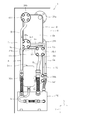
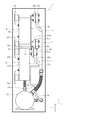
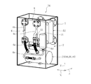
図2は本発明の第1実施形態に係る熱利用装置1の透視斜視図であり、図3は熱利用装置の正面図、図4は熱利用装置の側面図、図5は熱利用装置の背面図である。熱利用装置1は、ランキン回路2の上記した各構成機器を板金等からなる直方体の筐体4内に収容することによりユニット化されている。筐体4には、何れも図示しないが、ランキン回路2の上記各構成機器にアクセス可能なメンテナンス用の開口、扉や、高温及び低温流路18、22の配管の挿通開口が適宜設けられている。また、筐体4内には上記各構成機器を支持、位置決めするためのフレーム(不図示)が適宜固定されている。
本実施形態では、蒸発器8及び凝縮器12は、真空断熱材等の断熱部材23を介して上下方向Yに並んで近接配置されている。具体的には、凝縮器12は蒸発器8の下側に配置されている。また、膨張機10、発電機20、及びポンプ16は、円筒状のハウジング内に収容された1つのユニット25とされ、このユニット25は凝縮器12の下側に配置され、筐体4の底部に固定されている。また、気液分離器14は、ユニット25よりも上側であって、図4の奥行方向Zで見て筐体4の正面板4a側に、凝縮器12と上下方向Yで一部が重なるようにして配置されている。
循環路6は、蒸発器8に対する冷媒の入口にフランジ接続される配管6a、蒸発器8に対する冷媒の出口にフランジ接続される配管6b、凝縮器12に対する冷媒の入口にフランジ接続される配管6c、凝縮器12に対する冷媒の出口にフランジ接続される配管6d、気液分離器14の出口に接続される配管6eを含む。これら配管6a~6eは蛇腹状のフレキシブル配管が適宜継手されて形成され、これより筐体4内におけるランキン回路2の上記各構成機器及び配管6a~6eの若干の変位が許容されている。
蒸発器8は、蒸発器正面8a、蒸発器正面8aの裏側である蒸発器背面8b、及び凝縮器12に対向する下面(蒸発器対向面)8cを有している。蒸発器正面8aには、冷媒入口となる第1入口フランジ26aと、冷媒出口となる第1出口フランジ26bとが上下に離間して突出されている。第1入口フランジ26aは図3で見て蒸発器正面8aの下側左隅に配置され、配管6aが接続された配管側フランジ6a1が締結されている。第1出口フランジ26bは図3で見て蒸発器正面8aの上側左隅に配置され、配管6bが接続された配管側フランジ6b1が締結されている。
図6(a)は、配管側フランジ6a1と配管6aとの接続態様を示す斜視図であり、図6(b)は図6(a)の平面図である。図6(a)、(b)に示すように、配管6aは配管側フランジ6a1の外周部6a2に例えばねじ込みや溶接等で接続されている。そして、配管側フランジ6a1には、冷媒の流れを第1入口フランジ26aの突出方向から第1入口フランジ26aの径方向に変える流路6a3が配管6aに連通するようにして穿孔されている。
また、配管側フランジ6a1に流路6a3内の冷媒圧力を導圧可能な導圧路6a4を穿孔し、この導圧路6a4を外周部6a2に開口しても良い。図6(a)、(b)の場合には、導圧路6a4は継手27で塞がれている。継手27には、圧力スイッチ、圧力センサ、安全弁、冷媒封入・排出用の遮断弁(何れも不図示)等を接続可能である。なお、配管側フランジ6b1、6c1も図6(a)、(b)のように形成される。
蒸発器背面8bには、高温熱媒体入口となる第2入口フランジ28aと、高温熱媒体出口となる第2入口フランジ28bとが上下に離間して突出されている。第2入口フランジ28aは図5で見て蒸発器背面8bの上側左隅に配置され、高温流路18の図示しない配管のフランジが締結される。第2出口フランジ28bは図5で見て蒸発器背面8bの下側左隅に配置され、高温流路18の図示しない配管のフランジが締結される。
凝縮器12は、凝縮器正面12a、凝縮器正面12aの裏側である凝縮器背面12b、及び蒸発器8に対向する上面(凝縮器対向面)12cを有している。凝縮器正面12aには、冷媒入口となる第3入口フランジ30aと、冷媒出口となる第3出口フランジ30bとが上下に離間して突出されている。第3入口フランジ30aは図3で見て凝縮器正面12aの上側右隅に配置され、配管6cが接続された配管側フランジ6c1が締結されている。第3出口フランジ30bは図3で見て凝縮器正面12aの下側右隅に配置され、配管6dが接続された配管側フランジ6d1が締結されている。なお、配管側フランジ6c1、6d1も図6(a)、(b)のように形成される。
また、図3及び図4に示すように、配管6dは気液分離器14側にはねじ込みや溶接等で接続される。しかし、これに限らず、図7の変形例に示すように、気液分離器14と凝縮器12との接続はフランジ接続であっても良い。この場合には、気液分離器14は、その周壁から突設された分離器側フランジ14aを有し、この分離器側フランジ14aが第3出口フランジ30bと直接に締結され、配管6dは不要となる。
一方、凝縮器背面12bには、低温熱媒体入口となる第4入口フランジ32aと、低温熱媒体出口となる第4入口フランジ32bとが上下に離間して突出されている。第4入口フランジ32aは図5で見て凝縮器背面12bの上側右隅に配置され、低温流路22の図示しない配管のフランジが締結される。第4出口フランジ32bは図5で見て凝縮器背面12bの下側右隅に配置され、低温流路22の図示しない配管のフランジが締結される。
このように、本実施形態の熱利用装置1では、蒸発器8及び凝縮器12は、筐体4内において、蒸発器正面8a及び凝縮器正面12aが直方体をなす筐体4の正面板4a(図4参照)と対向するように同じ側に向けて配置されている。即ち、図4から明らかなように、冷媒流通用の第1及び第3入出口フランジ26a、26b、30a、30bが若干の段差を有する蒸発器正面8a及び凝縮器正面12aに設けられる一方、熱媒体流通用の第2及び第4入出口フランジ28a、28b、32a、32bが略面一をなす蒸発器背面8b及び凝縮器背面12bに設けられている。
これにより、蒸発器正面8a及び凝縮器正面12a側に第1~第4入出口フランジ26a、26b、28a、28b、30a、30b、32a、32bをすべて集約して設けた従来の場合に比して、蒸発器正面8a及び凝縮器正面12a、蒸発器背面8b及び凝縮器背面12bの面積を小さくすることができる。
また、第1及び第3入出口フランジ26a、26b、30a、30bは、水平方向Xで見て蒸発器8の下面8c及び凝縮器12の上面12cを隔てた蒸発器正面8a及び凝縮器正面12aの左右の逆側端にそれぞれ配置されている。また、第2及び第4入出口フランジ28a、28b、32a、32bは、水平方向Xで見て蒸発器8の下面8c及び凝縮器12の上面12cを隔てた蒸発器背面8b及び凝縮器背面12bの左右の逆側端にそれぞれ配置されている。
また、第1及び第3入出口フランジ26a、26b、30a、30bは、水平方向Xで見て蒸発器8の下面8c及び凝縮器12の上面12cを隔てた蒸発器正面8a及び凝縮器正面12aの左右の逆側端にそれぞれ配置されている。また、第2及び第4入出口フランジ28a、28b、32a、32bは、水平方向Xで見て蒸発器8の下面8c及び凝縮器12の上面12cを隔てた蒸発器背面8b及び凝縮器背面12bの左右の逆側端にそれぞれ配置されている。
以上のように本実施形態の場合には、上下に隣り合う蒸発器8及び凝縮器12の第1~第4入出口フランジ26a、26b、28a、28b、30a、30b、32a、32b同士が接触干渉することが回避され、上記従来の場合のようにフランジ同士の接触干渉を避けるために筐体4内にデットスペースが発生することもない。従って、熱利用装置1全体のより一層の小型化を実現することができる。
しかも、冷媒流通用の第1及び第3入出口フランジ26a、26b、30a、30bを蒸発器正面8a及び凝縮器正面12aに設ける一方、熱媒体流通用の第2及び第4入出口フランジ28a、28b、32a、32bを蒸発器背面8b及び凝縮器背面12bに設けたことにより、上記従来の場合に比して、冷媒流通関連と熱媒体流通関連とに分けて熱利用装置1の組み立てやメンテナンスを行うことができる。従って、上記従来の場合に比して、熱利用装置1のメンテナンス性及び組立性を向上することができる。
また、配管6aを配管側フランジ6a1の外周部6a2に接続し、更には、気液分離器14の分離器側フランジ14aを第3出口フランジ30bと直接に締結して配管6dを排除した場合には、熱利用装置1の奥行方向Zの幅をより一層低減することができるため、熱利用装置1の更なる小型化を実現することができる。
また、凝縮器12が蒸発器8の下側に配置され、また、ユニット25ひいてはポンプ16が凝縮器12の下側に配置されていることにより、熱利用装置1の作動が停止したとき、液冷媒が重力により凝縮器12を経てポンプ16の入口に自然に流下する。これにより、熱利用装置1の再起動時におけるポンプ16への気相冷媒流入を確実に防止し、ポンプ16が不具合なく冷媒を圧送することができる。また、蒸発器8と凝縮器12との間には断熱部材23を配置することにより、蒸発器8と凝縮器12とを近接配置しても、互いの熱伝導を抑制可能なる。従って、これらにより熱利用装置1の信頼性をも向上することができる。
図8は本発明の第2実施形態に係る熱利用装置34の透視斜視図であり、図9は熱利用装置34の正面図、図10は熱利用装置34の側面図、図11は熱利用装置の背面図である。この熱利用装置34と第1実施形態の熱利用装置1との相違点は、主として、ランキン回路4の各構成機器の配置、配管6a~6eの引き回し、筐体4の形状であり、その他の構成については同符号を付して説明を省略することがある。
具体的には、本実施形態では、蒸発器8及び凝縮器12は断熱部材23を介して水平方向Xに並んで近接配置されている。具体的には、図8で見て凝縮器12は蒸発器8の右側に配置されている。また、ユニット25は凝縮器12の下側に配置され、筐体4の底部に固定されている。また、気液分離器14は、ユニット25よりも上側であって、図10の奥行方向Zで見て筐体4の正面板4a側に、凝縮器12と上下方向Yで一部が重なるようにして配置されている。
本実施形態の熱利用装置34でも、第1実施形態の場合と同様に、蒸発器8及び凝縮器12は、筐体4内において、蒸発器正面8a及び凝縮器正面12aが筐体4の正面板4aと対向するように同じ側に向けて配置されている。即ち、冷媒流通用の第1及び第3入出口フランジ26a、26b、30a、30bが略面一をなす蒸発器正面8a及び凝縮器正面12aに設けられる一方、熱媒体流通用の第2及び第4入出口フランジ28a、28b、32a、32bが略面一をなす蒸発器背面8b及び凝縮器背面12bに設けられている。これにより、従来の場合に比して、蒸発器正面8a及び凝縮器正面12a、蒸発器背面8b及び凝縮器背面12bの面積を小さくすることができる。
また、第1及び第3入出口フランジ26a、26b、30a、30bは、図9の水平方向Xで見て蒸発器8の右側面(蒸発器対向面)8d及び凝縮器12の左側面(凝縮器対向面)12dを隔てた蒸発器正面8a及び凝縮器正面12aの左側端にそれぞれ配置されている。また、第2及び第4入出口フランジ28a、28b、32a、32bは、図11の水平方向Xで見て蒸発器8の下面8c及び凝縮器12の上面12cを隔てた蒸発器背面8b及び凝縮器背面12bの左側端にそれぞれ配置されている。
以上のように本実施形態の場合には、左右に隣り合う蒸発器8及び凝縮器12の第1~第4入出口フランジ26a、26b、28a、28b、30a、30b、32a、32b同士が接触干渉することが回避され、第1実施形態の場合と同様に、熱利用装置1全体のより一層の小型化を実現することができ、しかも、熱利用装置1のメンテナンス性及び組立性を向上することができる。
また、第1実施形態の場合と同様に、図6(a)、(b)、図7に示したように、配管6aを配管側フランジ6a1の外周部6a2に接続し、更には、気液分離器14の分離器側フランジ14aを第3出口フランジ30bと直接に締結して配管6dを排除することも可能である。この場合には、熱利用装置1の奥行方向Zの幅をより一層低減することができるため、熱利用装置1の更なる小型化を実現することができる。
また、第1実施形態の場合と同様に、ユニット25ひいてはポンプ16が凝縮器12の下側に配置し、また、蒸発器8と凝縮器12との間には断熱部材23を配置することにより、温度帯の異なる蒸発器8と凝縮器12との間における熱移動を阻止しながら、蒸発器8及び凝縮器12を隣接させることができ、ひいては熱利用装置1のより一層の小型化を実現することができる。
以上で本発明の各実施形態についての説明を終えるが、本発明はこれら形態に限定されるものではなく、本発明の趣旨を逸脱しない範囲で種々の変更ができるものである。
以上で本発明の各実施形態についての説明を終えるが、本発明はこれら形態に限定されるものではなく、本発明の趣旨を逸脱しない範囲で種々の変更ができるものである。
例えば、上記各実施形態の第1~第4入出口フランジ26a、26b、28a、28b、30a、30b、32a、32bの配置に限らず、蒸発器8及び凝縮器12にて、蒸発器対向面及び凝縮器対向面を隔てて、第1~第4入出口フランジ26a、26b、28a、28b、30a、30b、32a、32bが少なくとも上下方向及び水平方向の何れか一方にずれた位置に配置されていれば良い。この場合であっても、蒸発器正面8a及び凝縮器正面12a、蒸発器背面8b及び凝縮器背面12bの面積を小さくすることができ、第1~第4入出口フランジ26a、26b、28a、28b、30a、30b、32a、32b同士が接触干渉することが回避され、熱利用装置1全体のより一層の小型化を実現することができる。
また、上記各実施形態では、膨張機10、発電機20、及びポンプ16を一体に収容したユニット25を備える場合について説明したが、これら膨張機10、発電機20、及びポンプ16を個別に配置しても良い。また、モータ機能を有さない発電機20を使用し、図示しないモータを別途個別に配置しても良い。
また、上記各実施形態では、循環路6は、配管6a~6eを蛇腹状のフレキシブル配管で適宜継手されて形成される。しかし、これに限らず、フレキシブル配管の代わりにゴムホース等を使用しても良い。
また、上記各実施形態では、循環路6は、配管6a~6eを蛇腹状のフレキシブル配管で適宜継手されて形成される。しかし、これに限らず、フレキシブル配管の代わりにゴムホース等を使用しても良い。
また、上記各実施形態では、蒸発器8、凝縮器12がそれぞれ1つずつ配置される場合について説明したが、これに限らず、蒸発器8、凝縮器12をそれぞれ複数設置しても良い。この場合、蒸発器8、凝縮器12は、作動流体や熱媒体の流れに対し、直列に連結しても良いし、並列に連結しても良い。
また、上記各実施形態では、熱利用装置1,34の熱源は工場の排熱としたが、これに限らず、温泉地等の地熱や、車両等のエンジンからの排熱等の種々の未利用熱を熱源としても良い。
また、上記各実施形態では、熱利用装置1,34の熱源は工場の排熱としたが、これに限らず、温泉地等の地熱や、車両等のエンジンからの排熱等の種々の未利用熱を熱源としても良い。
1、34 熱利用装置
2 ランキン回路
4 筐体
6 循環路
6a、6b 配管
6c、6d 配管
6a1、6b1、6c1、6d1 配管側フランジ
6a2 外周部
6a3 流路
8 蒸発器
8a 蒸発器正面
8b 蒸発器背面
8c 下面(蒸発器対向面)
8d 右側面(蒸発器対向面)
10 膨張機
12 凝縮器
12a 凝縮器正面
12b 凝縮器背面
12c 上面(凝縮器対向面)
12d 左側面(凝縮器対向面)
14 気液分離器
14a 分離器側フランジ
16 ポンプ
18 高温流路
22 低温流路
23 断熱部材(真空断熱材)
26a 第1入口フランジ
26b 第1出口フランジ
28a 第2入口フランジ
28b 第2出口フランジ
30a 第3入口フランジ
30b 第3出口フランジ
32a 第4入口フランジ
32b 第4出口フランジ
2 ランキン回路
4 筐体
6 循環路
6a、6b 配管
6c、6d 配管
6a1、6b1、6c1、6d1 配管側フランジ
6a2 外周部
6a3 流路
8 蒸発器
8a 蒸発器正面
8b 蒸発器背面
8c 下面(蒸発器対向面)
8d 右側面(蒸発器対向面)
10 膨張機
12 凝縮器
12a 凝縮器正面
12b 凝縮器背面
12c 上面(凝縮器対向面)
12d 左側面(凝縮器対向面)
14 気液分離器
14a 分離器側フランジ
16 ポンプ
18 高温流路
22 低温流路
23 断熱部材(真空断熱材)
26a 第1入口フランジ
26b 第1出口フランジ
28a 第2入口フランジ
28b 第2出口フランジ
30a 第3入口フランジ
30b 第3出口フランジ
32a 第4入口フランジ
32b 第4出口フランジ
Claims (10)
- 作動媒体が循環する循環路に、高温流路を流れる高温熱媒体から熱回収して前記作動媒体を加熱する蒸発器、該蒸発器を経由した作動媒体を膨張させて駆動力を発生する膨張機、該膨張機を経由した作動媒体を低温流路を流れる低温熱媒体により冷却して凝縮させる凝縮器、及び、該凝縮器を経由した作動媒体を前記蒸発器に向けて圧送するポンプが少なくとも順次介挿されてなるランキン回路と、
前記ランキン回路が収容される筐体と
を備え、
前記蒸発器は、上下に離間して突出されるとともに、前記循環路の配管が接続される一対の第1入出口フランジを有する蒸発器正面、前記蒸発器正面の裏側であって、上下に離間して突出されるとともに、前記高温流路の配管が接続される一対の第2入出口フランジを有する蒸発器背面、及び、前記凝縮器に対向する蒸発器対向面を有し、
前記凝縮器は、上下に離間して突出されるとともに、前記循環路の配管が接続される一対の第3入出口フランジを有する凝縮器正面、前記凝縮器正面の裏側であって、上下に離間して突出されるとともに、前記低温流路の配管が接続される一対の第4入出口フランジを有する凝縮器背面、及び、前記蒸発器対向面に対向する凝縮器対向面を有し、
前記蒸発器及び前記凝縮器は、前記筐体内において、前記蒸発器正面及び前記凝縮器正面、前記蒸発器背面及び前記凝縮器背面がそれぞれ同じ側に向けて配置されている、熱利用装置。 - 前記蒸発器及び前記凝縮器は、前記蒸発器対向面及び前記凝縮器対向面を隔てて、前記第1~第4入出口フランジが少なくとも上下方向及び水平方向の何れか一方にずれた位置に配置されている、請求項1に記載の熱利用装置。
(*前記第1~第4入出口フランジが少なくとも上下方向及び水平方向の何れか一方にずれた位置に配置:各フランジが上下、水平、上下水平双方(つまり、ねじれ方向)の何れかにずれて、互いに非接触となる状態を意味します。この記載は、各実施形態のパターンを網羅するものです。これにより、デッドスペースが排除でき、コンパクト化が促進可能となります。) - 前記蒸発器及び前記凝縮器は上下方向に並んで配置され、
前記第1及び第3入出口フランジは、水平方向で見て前記蒸発器対向面及び前記凝縮器対向面を隔てた前記蒸発器正面及び前記凝縮器正面の逆側端にそれぞれ配置され、
前記第2及び第4入出口フランジは、水平方向で見て前記蒸発器対向面及び前記凝縮器対向面を隔てた前記蒸発器背面及び前記凝縮器背面の逆側端にそれぞれ配置されている、請求項2に記載の熱利用装置。 - 前記凝縮器は前記蒸発器の下側に配置されている、請求項3に記載の熱利用装置。
- 前記ポンプは前記凝縮器の下側に配置されている、請求項3又は4に記載の熱利用装置。
- 前記蒸発器及び前記凝縮器は水平方向に並んで配置され、
前記第1及び第3入出口フランジは、水平方向で見て前記蒸発器対向面及び前記凝縮器対向面を隔てた前記蒸発器正面及び前記凝縮器正面の同側端にそれぞれ配置され、
前記第2及び第4入出口フランジは、水平方向で見て前記蒸発器対向面及び前記凝縮器対向面を隔てた前記蒸発器背面及び前記凝縮器背面の同側端にそれぞれ配置されている、請求項2に記載の熱利用装置。 - 前記第1及び第3入出口フランジには、それぞれ配管側フランジが締結され、
前記配管側フランジの外周部に前記循環路の配管が接続され、前記配管側フランジには、前記作動媒体の流れを前記第1及び第3入出口フランジの突出方向から前記第1及び第3入出口フランジの径方向に変える流路が前記循環路の配管に連通するようにして形成されている、請求項1から6の何れか一項に記載の熱利用装置。 - 前記ランキン回路は、前記凝縮器と前記ポンプとの間に介挿され、前記凝縮器で凝縮された作動媒体を気液分離し、該分離された液体の作動媒体のみを前記ポンプ側に流出する気液分離器を更に備え、
前記気液分離器は、その周壁から突設された分離器側フランジを有し、該分離器側フランジが前記第3出口フランジと直接に接続される、請求項1から7の何れか一項に記載の熱利用装置。 - 前記蒸発器と前記凝縮器との間には断熱部材が配置されている、請求項1から8の何れか一項に記載の熱利用装置。
- 前記断熱部材は真空断熱材である、請求項9に記載の熱利用装置。
Applications Claiming Priority (2)
| Application Number | Priority Date | Filing Date | Title |
|---|---|---|---|
| JP2015113111A JP6576106B2 (ja) | 2015-06-03 | 2015-06-03 | 熱利用装置 |
| JP2015-113111 | 2015-06-03 |
Publications (1)
| Publication Number | Publication Date |
|---|---|
| WO2016195022A1 true WO2016195022A1 (ja) | 2016-12-08 |
Family
ID=57440497
Family Applications (1)
| Application Number | Title | Priority Date | Filing Date |
|---|---|---|---|
| PCT/JP2016/066422 Ceased WO2016195022A1 (ja) | 2015-06-03 | 2016-06-02 | 熱利用装置 |
Country Status (2)
| Country | Link |
|---|---|
| JP (1) | JP6576106B2 (ja) |
| WO (1) | WO2016195022A1 (ja) |
Cited By (1)
| Publication number | Priority date | Publication date | Assignee | Title |
|---|---|---|---|---|
| SE2350127A1 (en) * | 2023-02-10 | 2024-08-11 | Climeon Ab | Thermodynamic system comprising a pump assembly |
Families Citing this family (1)
| Publication number | Priority date | Publication date | Assignee | Title |
|---|---|---|---|---|
| KR102519041B1 (ko) * | 2021-07-06 | 2023-04-11 | 에이치디한국조선해양 주식회사 | 연료공급 시스템 및 이를 포함하는 선박 |
Citations (4)
| Publication number | Priority date | Publication date | Assignee | Title |
|---|---|---|---|---|
| JP2013007369A (ja) * | 2011-06-27 | 2013-01-10 | Ihi Corp | 廃熱発電装置 |
| JP2013011182A (ja) * | 2011-06-28 | 2013-01-17 | Ihi Corp | 廃熱発電装置 |
| JP2013032725A (ja) * | 2011-08-01 | 2013-02-14 | Ihi Corp | 発電装置 |
| US8813500B2 (en) * | 2011-08-03 | 2014-08-26 | Dresser-Rand Company | Combined heat exchanger expander mounting system |
-
2015
- 2015-06-03 JP JP2015113111A patent/JP6576106B2/ja not_active Expired - Fee Related
-
2016
- 2016-06-02 WO PCT/JP2016/066422 patent/WO2016195022A1/ja not_active Ceased
Patent Citations (4)
| Publication number | Priority date | Publication date | Assignee | Title |
|---|---|---|---|---|
| JP2013007369A (ja) * | 2011-06-27 | 2013-01-10 | Ihi Corp | 廃熱発電装置 |
| JP2013011182A (ja) * | 2011-06-28 | 2013-01-17 | Ihi Corp | 廃熱発電装置 |
| JP2013032725A (ja) * | 2011-08-01 | 2013-02-14 | Ihi Corp | 発電装置 |
| US8813500B2 (en) * | 2011-08-03 | 2014-08-26 | Dresser-Rand Company | Combined heat exchanger expander mounting system |
Cited By (3)
| Publication number | Priority date | Publication date | Assignee | Title |
|---|---|---|---|---|
| SE2350127A1 (en) * | 2023-02-10 | 2024-08-11 | Climeon Ab | Thermodynamic system comprising a pump assembly |
| WO2024167457A1 (en) * | 2023-02-10 | 2024-08-15 | Climeon Ab | Arrangement for condensing and circulating fluid in a system |
| SE547323C2 (en) * | 2023-02-10 | 2025-07-01 | Climeon Ab | Thermodynamic system comprising a pump assembly |
Also Published As
| Publication number | Publication date |
|---|---|
| JP6576106B2 (ja) | 2019-09-18 |
| JP2016223408A (ja) | 2016-12-28 |
Similar Documents
| Publication | Publication Date | Title |
|---|---|---|
| TW534971B (en) | Heat pumping installation, in particular with a refrigeration function | |
| US10161687B2 (en) | Plate heat exchanger and heat pump outdoor unit | |
| US9823025B2 (en) | Heat recovery system having a plate heat exchanger | |
| US10401094B2 (en) | Brazed plate heat exchanger for water-cooled heat rejection in a refrigeration cycle | |
| JP5881515B2 (ja) | プレート式熱交換器およびその製造方法並びにヒートポンプ装置 | |
| JP2013064583A (ja) | 車両用熱交換器 | |
| CN104420903B (zh) | 空冷单元 | |
| JP6576106B2 (ja) | 熱利用装置 | |
| CN112436653B (zh) | 电机组件、热管理设备和热管理系统 | |
| JP2016200368A (ja) | ヒートポンプ装置および給湯装置 | |
| JP6242769B2 (ja) | 圧縮装置 | |
| JP2018028393A (ja) | 空気調和装置の室外機のモータ種別判定装置及びモータ種別判定方法 | |
| CN213637312U (zh) | 电机组件、热管理设备和热管理系统 | |
| JP6850132B2 (ja) | 衣類乾燥機 | |
| JP5619698B2 (ja) | 地中熱ヒートポンプ装置 | |
| JP6207124B2 (ja) | バイナリー発電装置 | |
| KR101896763B1 (ko) | 펌프구동용 모터 냉각장치 | |
| CN108729168B (zh) | 衣物干燥机 | |
| JP6371139B2 (ja) | 切替方法 | |
| KR20150017610A (ko) | 압축기 시스템 | |
| JP2011007467A (ja) | プレート式熱交換容器 | |
| JPH10227586A (ja) | 沸騰冷却器および筐体冷却装置 | |
| JP2015140669A (ja) | 廃熱回生システム | |
| JP2024007225A (ja) | バイナリ発電ユニット、及び、バイナリ発電システム | |
| WO2015128900A1 (ja) | 熱移動装置 |
Legal Events
| Date | Code | Title | Description |
|---|---|---|---|
| 121 | Ep: the epo has been informed by wipo that ep was designated in this application |
Ref document number: 16803456 Country of ref document: EP Kind code of ref document: A1 |
|
| NENP | Non-entry into the national phase |
Ref country code: DE |
|
| 122 | Ep: pct application non-entry in european phase |
Ref document number: 16803456 Country of ref document: EP Kind code of ref document: A1 |